
PTZ Keyboard - Remote control BirdDog - Free user manual and instructions
Find the device manual for free PTZ Keyboard BirdDog in PDF.


| Brand | BirdDog |
| Model | PTZ Keyboard |
| Category | PTZ Remote Control |
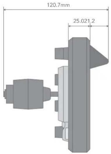
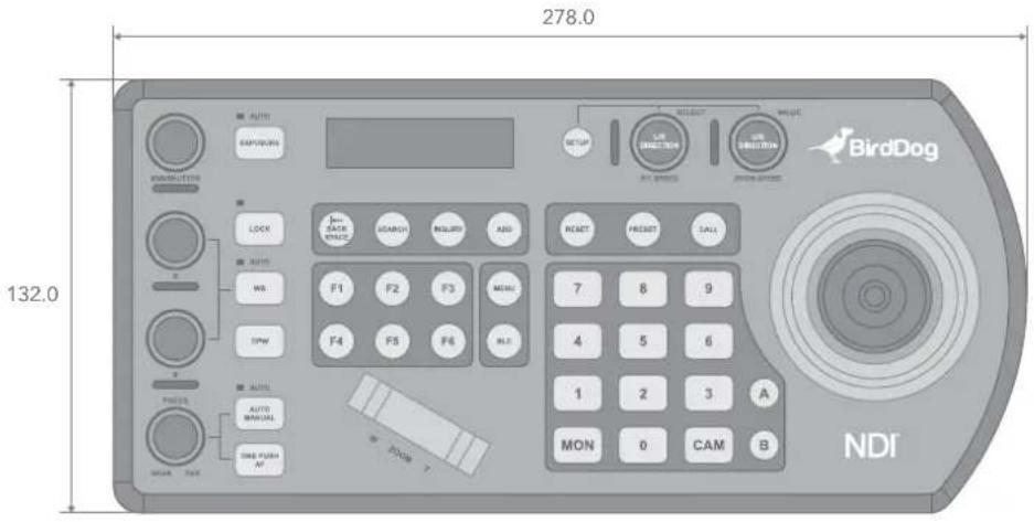
| Dimensions (W x D x H) | 278 mm x 132 mm x 120.7 mm |
| Power Input | 12V DC (5-48V tolerance) or PoE (802.3af) |
| Supported Protocols | NDI®, NDI®|HX, VISCA, VISCA over IP, PELCO D/P, RS232, RS422, RS485 |
| Control Methods | 6-way joystick, zoom seesaw, alphanumeric keypad, dedicated knobs, function keys |
| Maximum Cameras Controlled | 255 total (mix of protocols); 7 per RS422 group (2 groups), 255 RS485 PELCO |
| Presets | Up to 256 camera presets |
| Tally | Yes, with GPI I/O (Standard/Expand modes) |
| Display | LCD screen for menu navigation and camera info |
| Button Backlight | Adjustable brightness |
| Firmware Upgrade | Via USB port on rear panel |
| Network Interface | RJ-45 IP port (NDI, PoE), RJ-45 RS232, 2x RJ-45 RS422 A/B |
| Audio | Audio port for headset (BirdDog Comms) |
| Security | Kensington lock slot |
| Included Accessories | Power adaptor, junction box, RJ45 control cable, tally terminal contact |
| Optional Accessories | RJ45 to Phoenix breakout, RJ45 coupler, RS232 8-pin Mini Din to Phoenix |
| Cleaning | Wipe with a soft dry cloth; do not use chemicals |
| Safety | Installation by qualified personnel; do not disassemble; ensure correct voltage |
Frequently Asked Questions - PTZ Keyboard BirdDog
User questions about PTZ Keyboard BirdDog
0 question about this device. Answer the ones you know or ask your own.
Ask a new question about this device
Download the instructions for your Remote control in PDF format for free! Find your manual PTZ Keyboard - BirdDog and take your electronic device back in hand. On this page are published all the documents necessary for the use of your device. PTZ Keyboard by BirdDog.
USER MANUAL PTZ Keyboard BirdDog
WORLD'S FIRST NDI® PTZ CONTROLLER.
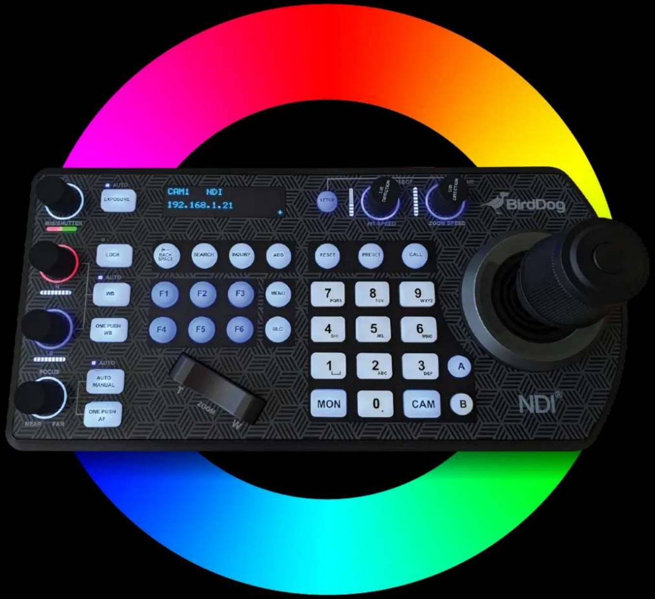
Table of Contents
Welcome to BirdDog ....3
Using This Manual....3
First Step 3
Overview of the PTZ Keyboard 4
Key Features....4
Welcome to the Future ....5
What's in the Box? 6
Optional Accessories 6
Getting Started With Your PTZ Keyboard ....7
Your PTZ Keyboard at a Glance....7
Connections....8
Keyboard Main Panel ....10
Keyboard Rear Panel 12
Keyboard Screen 13
Junction Box 14
Powering the PTZ Keyboard 15
Power Supply (included)....15
PoE....15
Junction Box (included)....15
Connecting the PTZ Keyboard to Your network 16
NDI® Connection....16
Other Control Protocols....16
Navigating the Menus 17
P/T Speed Dial....17
Zoom Speed Dial....17
Keyboard Configuration 17
Button Light....18
Function Key Assignment 18
Factory Reset Options 19
Tally - GPI I/O....19
Password Setting....19
Joystick Zoom Setting 20
Model Info....20
Adding an NDI ^® Camera to the Keyboard 21
Adding Cameras Manually 21
Adding non-NDI® Cameras to the Keyboard 21
Adding a VISCA over IP Camera to the PTZ Keyboard 22
Interacting With Cameras 24
Controlling Cameras.... 24
NDI® Keyboard Router 25
Setting and Calling Presets 26
Calling Presets 26
Resetting / Deleting Presets 26
Dual RS422 Button A/B 27
Adjusting Image Parameters 27
Web Configuration Panel 28
Password Management 28
BirdUI Layout....29
Dashboard 30
Network 31
NDI Network Settings 32
System 32
System Update....33
System Reboot 33
Access Manager Configuration....33
P/T Control 34
UI Mode 34
API Settings....35
Add Destination 35
Add Profile 36
Function Mode....36
API Example....37
Using Other Control Protocols 38
Cross-Protocol Mix Control....39
Cross Protocol Mix Control....41
Serial Port Connection....42
Tally Light GPI I/O Connection 51
Appendix 52
PTZ Keyboard Dimensions....53
Glossary 54
Copyright
Copyright 2023 BirdDog Australia all rights reserved. No part of this manual may be copied, reproduced, translated, or distributed in any form or by any means without prior consent in writing from our company.
Trademark Acknowledgement
BirdDog and other BirdDog trademarks and logos are the property of BirdDog Australia. Other trademarks, company names and product names contained in this manual are the property of their respective owners.
• Microsoft, Windows, ActiveX, and Internet Explorer are registered trademarks of Microsoft Corporation in the U.S. and/or other countries.
- HDMI, the HDMI logo and High-Definition Multimedia Interface are the trademarks or registered trademarks of HDMI Licensing, LLC in the United States and other countries.
- Other trademarks, company names and product names contained in this manual are the property of their respective owners.
- NDI ^ is a registered trademark of NewTek, Inc.
Important Information
Legal Notice
To ensure account security, please change the password after your first login. You are recommended to set a strong password (no less than eight characters).
The contents of this document are subject to change without prior notice. Updates will be added to the new version of this manual. We will readily improve or update the products or procedures described in the manual.
Best effort has been made to verify the integrity and correctness of the contents in this document, but no statement, information, or recommendation in this manual shall constitute formal guarantee of any kind, expressed or implied. We shall not be held responsible for any technical or typographical errors in this manual.
The product appearance shown in this manual is for reference only and may be different from the actual appearance of your device.
Due to uncertainties such as physical environment, discrepancy may exist between the actual values and reference values provided in this manual. Use of this document and the subsequent results shall be entirely on the user's own responsibility.
Warnings
Installation and removal of the unit and its accessories must be carried out by qualified personnel. You must read all of the Safety Instructions supplied with your equipment before installation and operation.
- If the product does not work properly, please contact your dealer. Never attempt to disassemble the device yourself. (We will not assume any responsibility for problems caused by unauthorized repair or maintenance).
• This installation should be made by a qualified service person and should conform to all the local codes.
• When shipping, the device should be packed in its original packaging.
• Make sure the power supply voltage is correct before using the device.
- Do not drop the device or subject it to physical shock.
Regulatory Compliance
FCC Part 15
This equipment has been tested and found to comply with the limits for digital device, pursuant to part 15 of the FCC Rules. These limits are designed to provide reasonable protection against harmful interference when the equipment is operated in a commercial environment.
This equipment generates, uses, and can radiate radio frequency energy and, if not installed and used in accordance with the instruction manual, may cause harmful interference to radio communications. Operation of this equipment in a residential area is likely to cause harmful interference in which case the user will be required to correct the interference at his own expense.
This product complies with Part 15 of the FCC Rules. Operation is subject to the following two conditions:
•This device may not cause harmful interference.
- This device must accept any interference received, including interference that may cause undesired operation.
LVD/EMC Directive
This product complies with the European Low Voltage Directive 2006/95/EC and EMC Directive 2004/108/EC.
Welcome to BirdDog
Thank you for purchasing your BirdDog PTZ Keyboard. If you have any questions regarding the PTZ Keyboard, please contact your authorized dealer or view our PTZ Keyboard Knowledge Base.
Our website also has a User Stories page to help inspire you to get the most out of your new PTZ Keyboard.
Using This Manual
Your PTZ Keyboard is a powerful and sophisticated device, so please read this manual before use and retain for future reference.
If you are new to the world of NDI® or the PTZ Keyboard, begin with Getting Started With Your PTZ Keyboard. This will give you a good introduction to the setup of your device.
Tip
You can use controls in your browser or PDF reader to increase the page size when viewing the diagrams to reveal much more detail.
First Step
Firmware Upgrade
Before you use your new PTZ Keyboard, it's a good idea to upgrade to the latest firmware. We are always adding new features and improving the performance of our products, so installing the latest firmware will provide you with the best user experience.
To upgrade the firmware, please follow the Firmware Upgrade Instructions located in your firmware download folder and perform upgrade process.
The latest firmware files are available for download here: Firmware Updates
We're Invested in Your Success
We pride ourselves on being approachable and easily contactable. We'd love to hear from you.
Dan Miall
Co-Founder and CEO
dan@birddog.tv
Overview of the PTZ Keyboard
The BirdDog PTZ Keyboard is a full featured and versatile PTZ Keyboard that supports NDI®, NDI®|HX, Visca over IP, RS422, and RS232. By harnessing BirdDog's next generation NDI® and IP technology, it's never been easier to discover, connect, and control your PTZ cameras.
Key Features
- Wide protocol support: NDI®, VISCA, PELCO D/P, VISCA over IP.
•Cross protocol mix-control with RS232/RS422 and IP.
- Quick access of key camera functions.
•High quality 6-way joystick control.
- Independent wide-range dual power input: 12V DC, PoE.
Features
- Easy, ergonomic PTZ control of multiple remote cameras for live event production and content creation. Typical applications include: Education, Broadcast, Video Conferencing, House of Worship etc.
- This compact remote controller features a high-quality joystick that allows effortless one-handed pan tilt and zoom adjustments. Zoom can also be controlled via the joystick or a supplementary seesaw lever; dedicated knobs and control buttons simplify direct access to frequently-needed camera functions without needing to use the camera menus.
- Quick Access features include the control of Exposure, Shutter Speed, Iris, Compensation, White Balance, Focus, PT Speed, Zoom Speed.
- The controller supports serial RS232/RS422 and IP mix-control. It allows you to use RS232/RS422/IP control on one controller to control cameras in a single system.
- With IP control, automatically search available IP cameras in the network and assign IP addresses easily. IP control supports CGI and VISCA Over IP.
- Up to 256 camera presets with memory of image parameters and 8 patterns to recall camera moves (requires camera support).
•Tally Indicator: Includes Normal Tally/On-Air Tally/Contact Modes.
• Supports 2 groups (7 cameras per group) via VISCA RS422 daisy chain control. Unlimited number of controllers can operate on a single network to control up to 255 IP cameras. Controls up to total 255 cameras (Combine using PELCO/VISCA/VISCA-Over-IP Protocol). NOTE: Daisy chain connection of multiple cameras does not apply to BirdDog P100, P110 and P120 cameras.
• Up to 6 selectable ASSIGN function keys, allowing quick control of key camera functions.
•Multi-color Key/Button illumination indicator.
• Full compatibility is provided with all BirdDog PTZ cameras and Sony BRC, SRG series PTZ cameras and most PTZ cameras in the market that support IP/RS232/RS422/RS485 control.
• Regular MCU firmware upgrades via USB add new features to the PTZ Keyboard.
Welcome to the Future
What is NDI®?
Your new PTZ Keyboard has been designed to support the cutting edge NDI® video transmission standard.
NDI® (Network Device Interface) is a high-quality, low-latency, frame-accurate standard that enables compatible devices to communicate, and deliver and receive high definition video over your existing Gigabit Ethernet network.
Operating bi-directionally, NDI® devices can be auto-detected, powered and controlled over the same Ethernet cable used to send the video and audio. If you have a Gigabit network, you have the potential for a streamlined, interconnected, video production environment.
With the introduction of NDI® 5, you can now securely share network sources between remote sites anywhere in the world - on a single network port. Even a smartphone can be a NDI® source.
Transitioning to NDI® can also occur gradually. Existing SDI or HDMI signals can easily be converted to an NDI® stream and piped where required on your network and converted back only at the necessary endpoints.
BirdDog has been on the NDI® journey since the very beginning, and your PTZ Keyboard is just one of our products designed to take advantage of the features and potential of NDI®.
For more information on NDI ^® , please refer to this page on our website.

flowchart
graph TD
    A["Camera"] --> B["Switch"]
    C["Radio"] --> B
    D["Monitor"] --> B
    E["Laptop"] --> B
    B --> F["Display"]
    B --> G["Monitor"]
    B --> H["Monitor"]
What's in the Box?
1x BirdDog PTZ Keyboard
1x Power Adaptor & Power Cord
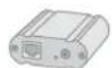
1x Junction box
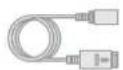
1x RJ45 Control Cable

1x Tally light Terminal Contact
Optional Accessories
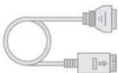
1x RJ45 to Phoenix Breakout

1x RJ45 Coupler
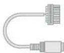
1x RS232 8 Pin Mini Din to Phoenix Terminal Block
Depending on your requirements, you may need to purchase these optional accessories:
- When RS422, RS485 and RS232 connected cameras are being controlled simultaneously. NOTE: Daisy chain connection of multiple cameras does not apply to BirdDog P100, P110 and P120 cameras.
- When more than one group of RS422/RS485 cameras is being controlled simultaneously.
- When a 8 Pin Mini Din RS232 connected camera needs to be connected to and controlled.
Please browse to this page on our website for all your accessory needs.
Getting Started With Your PTZ Keyboard
If you are new to the world of NDI® or BirdDog cameras, please follow this quick start guide to become familiar with the basic setup of your new camera.
Your PTZ Keyboard at a Glance
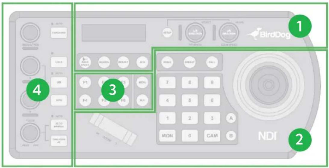
If you are new to PTZ Keyboard, it may be helpful to visualize the layout as follows.
1. LCD Screen and Navigation
• For navigating and adjusting the Keyboard settings. Interacting with IP cameras.
2. Camera Control
•PTZ Joystick
- For panning / tilting the camera in any direction and to zoom in / out.
•Alphanumeric Keypad
- For camera call, preset call, entering menu data.
•Separate zoom seesaw control.
3. Assign Keys
- Allow quick access to device commands.
4. Camera Image Adjustment
•Exposure, white balance and focus.
Connections
BirdDog products default to DHCP, so for the purposes of this quick start guide, we'll assume:
a. You are also using a managed DHCP IP configuration on your network.
b. You have connected NDI® cameras, such as the BirdDog P200.

flowchart
graph LR
    A["User Interface Device"] --> C["Switch"]
    B["Remote Display System"] --> C
    C --> D["Laptop"]
Power
You'll have to decide how you are going to power your Keyboard. You have two choices. You can use PoE (power over Ethernet) or, if your network doesn't support PoE, you can use the included 12V DC power adaptor. If available, PoE is the easier choice, since you can use the same Ethernet cable to power and control the camera, as well as send video.
Joystick Calibration
After booting up your Keyboard, please follow the instructions on the Keyboard screen to calibrate the Keyboard joystick control.
Network
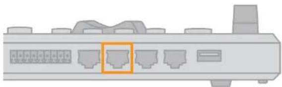
Plug an Ethernet cable from the switch to your Keyboard. Ensure that the cable is plugged into the NDI®/PoE capable port on the Keyboard, as shown below.
natural_image
Diagram of a network switch device with ports and an orange highlighted component (no text or labels)Camera Search
Two control knobs on the Keyboard are used to navigate the menus. Please refer to Navigating the Menus for more information.

flowchart
graph LR
    A["SEARCH"] --> B["KBD SETUP MENU"]
    B --> C["SELECT PROTOCOL"]
    C --> D["VISCA-IP"]
    D --> E["NDI-IP"]
    E --> F["EXIT"]
    B --> G["STATUS MENU"]
    G --> H["START SEARCH?"]
    H --> I["YES"]
    I --> J["NO & EXIT"]
    B --> K["DISCOVERED CAM."]
    K --> L["SEARCHED CAM: 1/5"]
    K --> M["192.168.0.101"]
    K --> N["EXIT"]
    L --> O["ADD"]
- Press the SEARCH button to display the SEARCH menu.
- Select NDI-IP as the Protocol. Click the P/T Speed dial.
- Select YES to start the search by once again clicking the P/T Speed dial.
- A list of discovered cameras will be displayed. Scroll through the cameras using the Zoom Speed dial.
- Press the ADD button to add the selected camera.
- With the cursor on CAM ID, assign the camera a number by rotating the Zoom Speed dial.
- Move the cursor to TITLE, click the P/T Speed dial to enter edit mode and use the alphanumeric keypad to give the camera a title suitable for your production.
- Exit this menu.
- Repeat this process for each discovered camera that you wish to add to the Keyboard.
- Test that you can call the camera by entering the CAM ID on the keypad (that you assigned) followed by the CAM button.
You're Done!
You should now have basic PTZ control of your camera. Please work your way through the rest of this manual so that you can familiarize yourself with the many features of the Keyboard.
Keyboard Main Panel
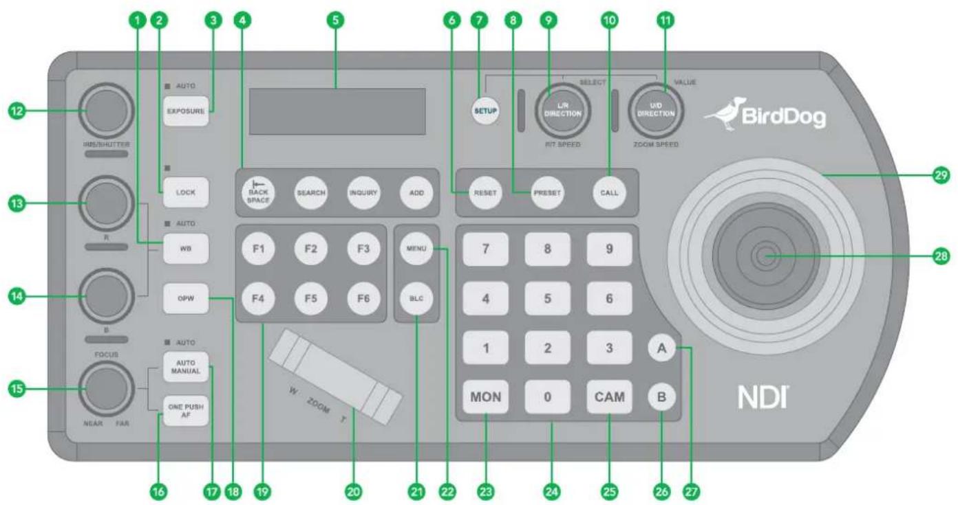
-
White Balance, (Auto, Manual)
-
Press once for Auto.
-
Press again to activate manual adjustments.
-
Lock
Locks all image adjustment buttons and dials.
- Exposure (Auto, Iris PRI, Shutter PRI)
- IP Interface Buttons
For interacting with IP cameras.
- LCD Screen
For navigating the Keyboard settings.
- Reset
For clearing presets.
- Setup
For Keyboard menu setting.
- Preset
For saving camera presets.
9. Pan Tilt Speed knob
- Rotate: Speed adjustment / Navigate (in menu).
- Press: Select (in menu).
- Long press (3 sec): Invert L/R direction.
10. Call
For calling camera presets.
11. Zoom Speed knob
- Rotate: Zoom speed adjustment / adjust value (in menu).
- Press: Save (in menu).
- Long press (3 sec): Invert U/D Direction.
12. IRIS / Shutter Adjustment for Exposure
13. Manual Red Adjustment for White Balance
14. Manual Blue Adjustment for White Balance
15. Manual Focus
16. One-Push Focus
17. Focus Auto/ Manual Toggle
18. OPW (One Push WB) For White Balance
19. Assign Keys
Allow quick access to commands.
20. Zoom Seesaw
21. BLC (Back Light Compensation)
Toggles Back Light Compensation setting in camera.
22. OSD Menu Button
23. MON
For calling monitor number (* Not activated for current versions).
24. Alphanumeric Keypad
For camera call, preset call, entering data (in menu).
25. CAM
For calling camera number.
26. RS422 Group B Selection
27. RS422 Group A Selection
28. Joystick Button
Keyboard Rear Panel
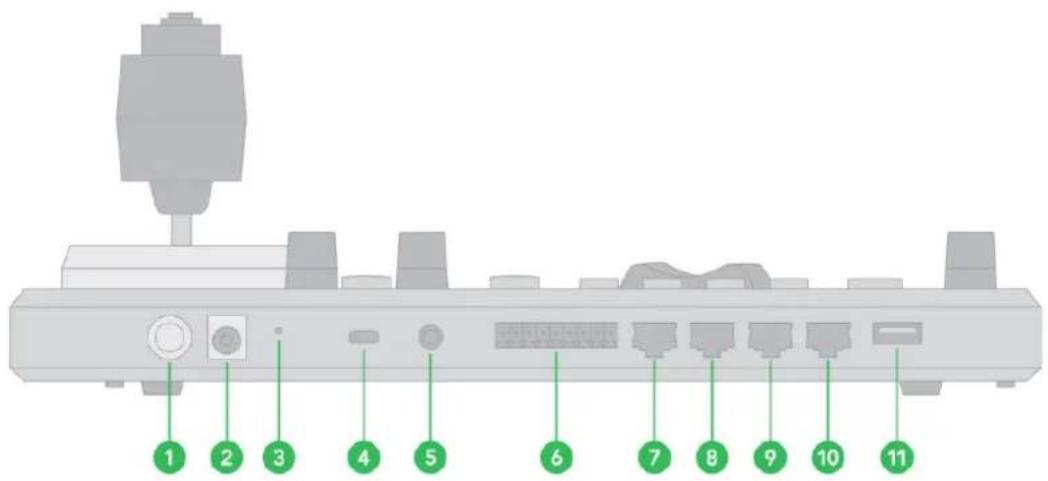
- Power Button
Power on / Power off the Keyboard.
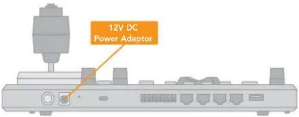
- 12V DC Power Port (range input tolerance: 5V-48V DC)
Connect the supplied DC power adaptor and cord.
- Hardware and Network Reset
Resets the Keyboard to its full factory defaults, including changing the network IP addressing to static.
- Kensington Security Slot
Use a lock to physically secure the Keyboard in place.
- Audio Port
For headset use when the Keyboard is added to a BirdDog Comms group.
- Tally / Contact (GPI I/O Connector)
Tally control interface.
- RS232 Interface / RJ-45 Port
Connect RS232 adapter.
- IP Interface / RJ-45 Port
Connect the Keyboard to a network.
- RS422 / RS485 (B) Interface / RJ-45 Port
Connect an RS422 adapter to control up to 7 daisy-chained RS422 cameras (Group A). NOTE: Daisy chain connection of multiple cameras does not apply to BirdDog P100, P110 and P120 cameras.
- RS422 / RS485 (A) Interface / RJ-45 Port
Connect an RS422 adapter to control up to 7 daisy-chained RS422 cameras (Group B).NOTE: Daisy chain connection of multiple cameras does not apply to BirdDog P100, P110 and P120 cameras.
- Firmware Upgrade USB port
Keyboard Screen
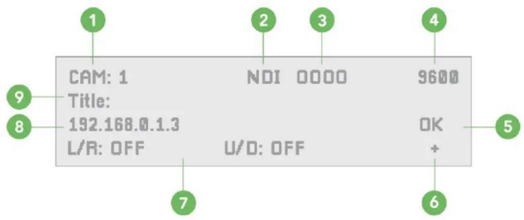
- Camera identifier
Identifies the camera being controlled. - Protocol
- TCP/UDP Port
- Baud Rate
- Communication Status Indicator (for the current device)
- Network connectivity Indicator
a. “+” displayed means that the network is successfully connected.
b. "+" not displayed means that the network is not connected.
- Tilt Reversal / Pan Reversal Indicator
- IP Address (of the currently controlled camera)
- Camera Title
Junction Box
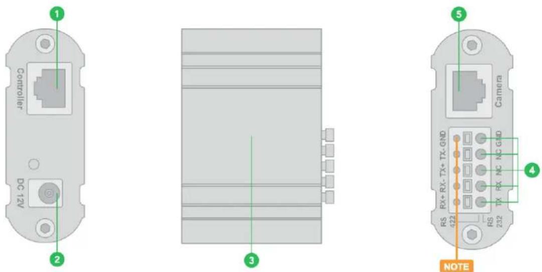
- RJ45 Port
For connection between Junction Box and The Keyboard Controller
- 12V DC Power Port
Connect the supplied DC power adaptor and cord.
-
Junction Box body
-
Terminal Contact Connection
For RS422 or RS232 use.
- RJ45 Port
For connection between Junction Box and the camera. Use a network cable to connect directly.
NOTE: Do not use the top row of holes, as these are not contact ports. All labels apply to the bottom row (Item #4 in the chart).
Powering the PTZ Keyboard
Power the Keyboard using one of the following options.
Power Supply (included)
•Power voltage tolerance = 5V - 48V.
•The Keyboard can be powered with at least 5V DC. This allows for longer power runs between the power source and the Keyboard.
•The Keyboard can also tolerate 48V DC power, which makes the Keyboard suitable for vehicle use (broadcast vans, commercial vehicles, etc.).
PoE
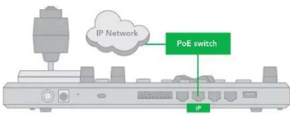
PoE is a convenient way to power the Keyboard as it allows both data and power to be sent through the same standard Ethernet cable. To take advantage of PoE, the network switch that the Keyboard is directly plugged into must support 15.4W PoE (802.3af).
- Connect the Ethernet IP port to PoE switch.
• Maximum distance of cable is 80m using CAT6 Plus cable.
Junction Box (included)
- Connect the Junction Box to the power supply.
- Connect an Ethernet cable from the controller port on the Junction Box to the RS422 or RS232 port on the Keyboard.
Power supply is required at EITHER the Keyboard OR the Junction Box.
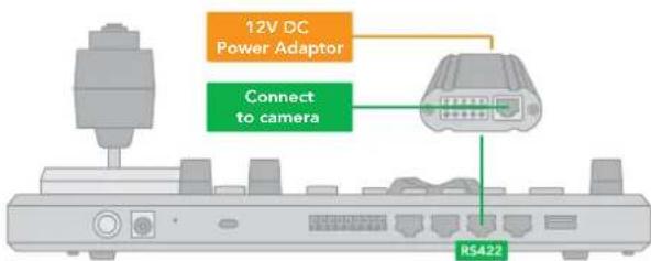
If the Junction Box is powered, no additional power supply is needed for the Keyboard, as the Junction Box will provide power to the Keyboard via the controller port.
Connecting the PTZ Keyboard to Your network
The Keyboard is the world's first PTZ controller with NDI® and NDI®|HX support. Along with NDI® there is support for Visca over IP, RS422, and RS232. You can mix and match cameras from any of the supported protocols and control them all from a single Keyboard.
NDI® Connection
Connect an Ethernet cable from the Keyboard's IP port to the Ethernet switch port. This connection allows you to use NDI® for camera control as well as using the WebUI for set up of the Keyboard. If supported by your switch, this same Ethernet cable connection enables you to power your Keyboard via PoE+.
With IP control, you can automatically search for available IP cameras in the network and easily assign IP addresses.
For more information on configurating Network and NDI® settings, please refer to Web User Interface Configuration Panel.
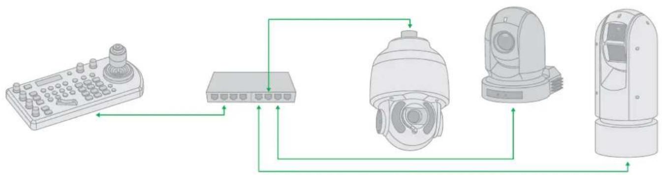
flowchart
graph TD
    A["Remote Control Device"] --> B["Switch"]
    B --> C["Security Camera Module"]
    C --> D["Monitor Module"]
    D --> E["Output"]
Other Control Protocols
Please refer to here for information on using the Keyboard with other control protocols.
Navigating the Menus
Press the SETUP button to display the SETUP menu on the LCD screen (Default Password: 0000).
The password can be changed at: SETUP > KEYBOARD SETTING > PASSWORD SETTING.
The following controls are used to navigate the menus and select/save parameter values. Use the P/T Speed dial to navigate the menus and the Zoom Speed dial to change and save your settings.
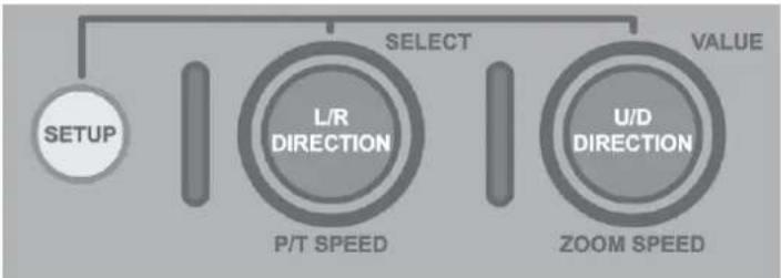
flowchart
graph TD
    A["SETUP"] --> B["L/R DIRECTION"]
    B --> C["P/T SPEED"]
    C --> D["SELECT"]
    D --> E["U/D DIRECTION"]
    E --> F["ZOOM SPEED"]
    F --> G["VALUE"]
P/T Speed Dial
- Rotate: Moves the cursor.
- Click: Selects the menu item.
Zoom Speed Dial
- Rotate: Change the value.
- Click: Save your value change.
Keyboard Configuration
Keyboard Setting Menu
Navigate to KEYBOARD SETTING in the MAIN SETUP MENU / IP Configuration.
The IP address can be set to either STATIC or DHCP (default).
DHCP
- Move the cursor to the TYPE field, and rotate the Zoom Speed dial to change the value to DHCP. Click the Zoom Speed dial to save.
Static
-
If setting the IP address to a STATIC address, ensure that the Type field displays STATIC, and then rotate the P/T Speed dial to move the cursor between the IP address octets. Move the cursor to each octet and use the alphanumeric keypad to enter its value. Rotate the P/T Speed dial to move to the next octet and repeat until all IP address octets are set to the desired values.
-
Click the Zoom Speed dial to save.
- Ensure that you enter the required SUBNET MASK and GATEWAY details.
- Click the Zoom Speed dial to save.
- Exit this menu.
Button Light
The BUTTON LIGHT value affects the brightness of the button backlight.
- Rotate the Zoom Speed dial to adjust the value.
- Click the Zoom Speed dial to save.
- Exit this menu.
Function Key Assignment
Keys can be configured as shortcuts to activate camera functions.
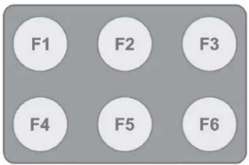
- From the Keyboard Setup menu, move the cursor to the ASSIGNED KEY field.
- Rotate the Zoom Speed dial to select the key to configure.
- Click the Zoom Speed dial to apply the function to the assigned key.
Keys can be assigned to the following camera features:
•Home: Command the selected camera to activate its 'Home' preset.
•P/T Reset: Reset the selected camera.
•Power: Power off the selected camera.
- Mute: Mute the audio from the selected camera.
•Picture Freeze: Freeze the image of the selected camera.
•Picture Flip: Flip the image of the selected camera.
• Picture LR Reverse: Invert the L/R (pan direction) of the selected camera.
- Camera 1-6: Cameras 1-6 stored in the Keyboard can be selected. (Default)
• None: No function will be assigned to the key.
- Exit.
Factory Reset Options
Factory Default
To clear all user changed OSD settings:
- From the KEYBOARD SETUP MENU, select FACTORY DEFAULT.
- Select YES.
NOTE: DO NOT move the joystick nor the Zooming control while the DEFAULT setting is processing.
Hardware and Network Reset
This resets the Keyboard to its full factory defaults, including changing the network IP addressing to static.
To perform the Hardware Reset:
- With the Keyboard turned ON, press the button inside the pinhole until the LCD shows "Factory Reset".
- Once the Keyboard has rebooted, you'll need to set your desired IP address settings in the SETUP / KEYBOARD SETTINGS / IP CONFIGURATION menu, the IP address will have been reset to a static address at 192.168.100.100.
Tally - GPI I/O
To configure the Tally settings.
Command Select
STANDARD: Sets the input/output method to Standard method. The camera numbers and input/output pin numbers have a 1:1 correspondence.
• If the unit and cameras are connected by serial connection, cameras 1 to 7 correspond to input/outputs 1 to 7.
- If the unit and cameras are connected by LAN connection, cameras 1 to 10 in group 1 correspond to input/outputs 1 to 10.
EXPAND: Handles camera numbers as binary numbers.
- Tally input numbers 8 and higher in a serial connection are ignored. In this case, the response is equivalent to no input.
- Numbers in a LAN connection, corresponding to cameras 1 to 10 in groups 1 to 10, are handled as the numbers 1 to 100. Tally input numbers 101 and higher are ignored. In this case, the response is equivalent to no input.
Password Setting
To change the password:
- OLD PASSWORD: Enter the current password.
- NEW PASSWORD: Enter the password you would like to set.
- CONFIRM: Enter the new password again to confirm.
- SAVE: Select this to apply the password. "OK" will display, confirming that the new password has been applied.
Joystick Zoom Setting
Change this setting to ON if you wish to use the joystick to control the camera's zoom. This setting can be changed by rotating the Zoom Speed knob while the setting is selected.
- Click the Zoom Speed knob to save this setting if changed.
• If this setting is set to "OFF", the Zoom Seesaw will remain active and can be used to control zoom.
Model Info
The Model info screen displays the current IP address, firmware version and MAC Address of the unit.
Adding an NDI® Camera to the Keyboard
Searching a Local Area Network (LAN)
Detect cameras on the network and add for Keyboard control.

flowchart
graph LR
    A["SEARCH"] --> B["KBD SETUP MENU"]
    B --> C["SELECT PROTOCOL VISCA-IP"]
    B --> D["NDI-IP EXIT"]
    B --> E["STATUS MENU START SEARCH? YES NO & EXIT"]
    B --> F["DISCOVERED CAM. SEARDED CAM: 1/5 192.168.0.101 EXIT"]
    G["ADD"] --> H["End"]
- Press the SEARCH button to display the Search menu.
- Move the cursor to NDI-IP.
- Select YES to start the search.
- A list of discovered cameras will be displayed. Scroll through the cameras using the Zoom Speed dial.
- To add a selected camera to be controlled by the Keyboard, press the ADD button.
- With the cursor on CAM ID, Assign the camera to a number by rotating the Zoom Speed dial.
- Move the cursor to the Title, and use the alphanumeric keypad to give the camera a title.
- Exit this menu.
- Repeat this process for each discovered camera that you wish to add to the Keyboard.
Adding Cameras Manually
- Navigate to the Protocol setting and select NDI.
- Click the P/T Speed dial to display the NDI Camera Setup menu.
- Enter the the IP address of the camera. The IP address of the camera needs to be within the same subnet as the Keyboard.
- Rotate the P/T Speed dial to move the cursor between the IP address octets.
- Move the cursor to each address octet and use the alphanumeric keypad to enter its value. Rotate the P/T Speed dial to move to the next octet and repeat until all address octets are set to the desired values.
- Click the Zoom Speed dial to save. Exit this menu.
Adding non-NDI® Cameras to the Keyboard
Manually adding cameras
NOTE: Daisy chain connection of multiple cameras does not apply to BirdDog P100, P110 and P120 cameras. The Keyboard can store settings to control up to:
•255 cameras by RS485 PELCO protocol separately.
- 7 cameras by VISCA via RS422 group A separately.
- 7 cameras by VISCA via RS422 group B separately.
•255 cameras by VISCA-Over-IP protocol separately.
• Total 255 cameras by cross protocol mix-controlling.
Use the Zoom Speed dial to select which camera slot to assign a camera. Each camera can be configured to be controlled using any of the following protocols: VISCA, PELCO-D, PELCO-P, VISCAIP (VISCA over IP), CGI.
If VISCA, PELCO-D, or PELCO-D are selected as the protocol, the Baud Rate Setting screen will be displayed. Use the Zoom Speed dial to set the baud rate. Click the Zoom Speed dial to save, and then exit this menu.
Adding a VISCA over IP Camera to the PTZ Keyboard
Adding a camera manually from Local Area Network (LAN)
Select VISCAIP (VISCA over IP) as the protocol and click the P/T Speed dial to display the VISCAIP configuration menu.
- Rotate the P/T Speed dial to move the cursor between the IP address octets. Move the cursor to each octet and use the alphanumeric keypad to enter its value. Rotate the P/T Speed dial to move to the next octet and repeat until all IP address octets are set to the desired values.
- Click the Zoom Speed dial to save.
- Exit this menu.
- Repeat this process for each camera that you wish to control with the Keyboard.
Scanning the Local Network for Available VISCA over IP Cameras

flowchart
graph LR
    A["SEARCH"] --> B["KBD SETUP MENU"]
    B --> C["SELECT PROTOCOL"]
    C --> D["VISCA-IP"]
    D --> E["EXIT"]
    B --> F["STATUS MENU"]
    F --> G["START SEARCH?"]
    G --> H["YES"]
    G --> I["NO & EXIT"]
    B --> J["DISCOVERED CAM."]
    J --> K["SEARCHED CAM: 1/5"]
    J --> L["192.168.0.101"]
    J --> M["EXIT"]
    N["ADD"] --> O["End"]
- Press the SEARCH button to display the SEARCH menu.
- Move the cursor to VISCA-IP.
- Select YES to start the search.
- A list of discovered cameras will display. Scroll through the list using the Zoom Speed dial.
- To add a camera to be controlled by the Keyboard, press the ADD button.
- With the cursor on CAM ID, assign the camera to a CAM ID by rotating the Zoom Speed dial.
- Click the Zoom Speed dial to save.
- Move the cursor to the TITLE, and use the alphanumeric keypad to give the camera a title.
- Click the Zoom Speed dial to save.
- Repeat this process for each discovered camera that you wish to add to Keyboard.
Adding VISCA over IP Cameras Under WAN Control
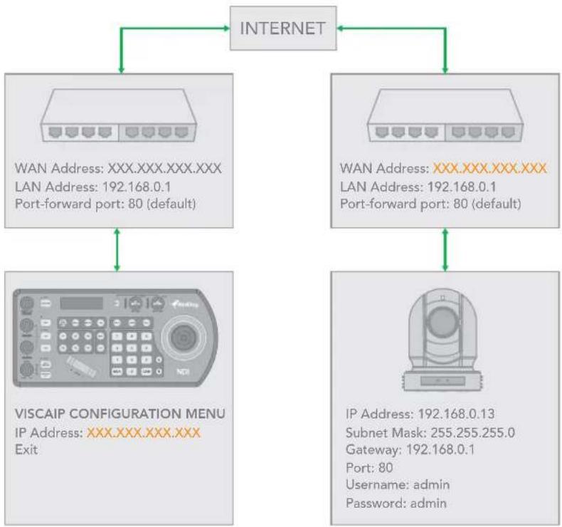
Make the following changes at the camera and Keyboard.
At the Camera Location
- For commands to flow from outside the network in to a camera, ports must be opened. Contact the network administrator at the camera location to create a port-forwarding rule in the router allowing commands to flow through the necessary ports using these values:
•Source/ external port: 52381
•Destination / internal port: 52381
•IP Address: IP Address of the camera
•Protocol: Both (TCP and UDP)
flowchart
graph TD
    A["INTERNET"] --> B["WAN Address: XXX.XXX.XXX.XXX LAN Address: 192.168.0.1 Port-forward port: 80 (default)"]
    A --> C["WAN Address: XXX.XXX.XXX.XXX LAN Address: 192.168.0.1 Port-forward port: 80 (default)"]
    A --> D["VISCAIP CONFIGURATION MENU IP Address: XXX.XXX.XXX.XXX Exit"]
    A --> E["IP Address: 192.168.0.13 Subnet Mask: 255.255.255.0 Gateway: 192.168.0.1 Port: 80 Username: admin Password: admin"]
At the Keyboard Location
- Set the Keyboard to DHCP.
- Contact the network administrator at the Keyboard location to create a port-forwarding rule in the router allowing commands to flow through the necessary ports using these values:
•Source/ external port: 52381.
•Destination / internal port: 52381.
•IP Address: IP Address of the Keyboard.
•Protocol: Both (TCP and UDP).
- In the Setup menu of the Keyboard:
a. Add the VISCA over IP camera using the WAN IP of the camera location as the IP Address.
b. Click the P/T Speed dial to save.
Interacting With Cameras
Options for Calling a Camera
- Use the keypad to call the camera by CAM ID.
a. Enter the CAM ID on the keypad.
b. Press CAM.
OR
- Call the IP cameras by selecting from a list of available devices.
a. Press the INQUIRY button.
b. Select a protocol,
c. Scroll through the list using the Zoom Speed dial.
d. Move the cursor to CALL, and click the P/T Speed dial.
| INQUIRY | CAMERA MENU | CAMERA MENU | CAMERA MENU |
| ▶ CAM001 1/5 VISCA | CAM001 1/5 VISCA | CAM: 1 VISCA | |
| TITLE: XXX | TITLE: XXX | ▶ YES | |
| 192.168.0.101 | 192.168.0.101 | 192.168.0.101 | |
| CALL EXIT | ▶ CALL EXIT |
Controlling Cameras
Engaging the Camera OSD Menu for non-IP Cameras
- Press the MENU button on the Keyboard to display the OSD menu.
-
Navigate the menu by using the joystick.
-
Move up / down to navigate through menu options.
- Move the joystick to the right to send an "Enter" command.
- Move up / down to adjust values.
- Move the joystick to the left to send an "Exit" command.
Engaging the Camera OSD Menu for PELCO-D Cameras
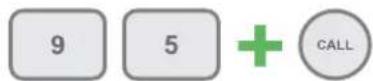
On the alphanumeric keypad, call preset 95 to engage the menu (type 95, and then press the CALL button).
Using the Joystick to Control Cameras
Joystick Calibration
Move the joystick up/down and left/right on bootup to calibrate the joystick. During this period, control movements will not be sent to the camera.
Joystick Movements
•Pan, Tilt, and Zoom movements can be executed simultaneously.
• The joystick can be used to pan / tilt the camera in any direction and rotated to zoom in / zoom out.

natural_image
Two gray icons: a starburst symbol with directional arrows and a circular arrow with plus sign, both on a gray background (no text or symbols)- When you are not in a menu, the P/T Speed and Zoom Speed dials control how fast the camera Pans, Tilts, and Zooms.
•Response to commands from the Keyboard.
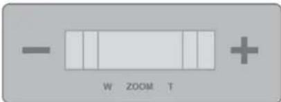
•The Zoom Seesaw can be engaged to zoom in / Zoom out.
NDI® Keyboard Router
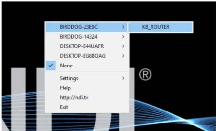
To allow for more efficient monitoring of cameras, the Keyboard outputs a video stream that follows the active controlled camera. To do this, select KB_ROUTER as the output channel of the desired NDI® sources.
Selecting Cam 1 on the Keyboard will display the Cam 1 NDI® stream, and then selecting Cam 2 on the Keyboard will display the Cam 2 NDI® stream. Importantly, this output is a ROUTER output therefore the media is not passing through the Keyboard and any device controls published by the camera source are accessible on the viewer (i.e. Tally, Web Configuration URL and PTZ Control).
Setting and Calling Presets
Creating Presets
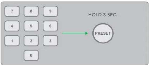
flowchart
graph LR
    A["7"] --> B["8"] --> C["9"]
    D["4"] --> E["5"] --> F["6"]
    G["1"] --> H["2"] --> I["3"]
    J["0"] --> K
    L["PRESET"] --> M["HOLD 3 SEC."]
- Move the camera to the desired position.
- Enter the desired preset number on the alphanumeric Keyboard, and then hold the PRESET button for 3 seconds to save.
Calling Presets
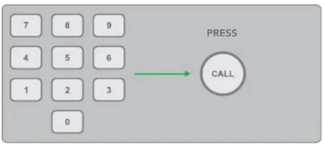
flowchart
graph TD
    A["7"] --> B["8"]
    B --> C["9"]
    D["4"] --> E["5"]
    E --> F["6"]
    G["1"] --> H["2"]
    H --> I["3"]
    J["0"] --> K["CALL"]
- Enter the preset number on the alphanumeric keypad.
- Press the CALL button.
Resetting / Deleting Presets
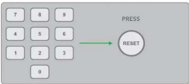
flowchart
graph LR
    A["7"] --> B["8"] --> C["9"]
    D["4"] --> E["5"] --> F["6"]
    G["1"] --> H["2"] --> I["3"]
    J["0"] --> K["0"]
    L["PRESS"] --> M["RESET"]
- Enter the number of the preset you wish to delete.
- Press the RESET button.
Dual RS422 Button A/B
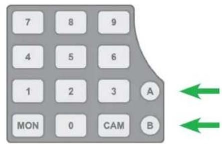
There are 2 RS422 ports on the back panel of the Keyboard. Up to 7 cameras can be daisy chained from each RS422 port. You can toggle between these by using the A and B buttons.
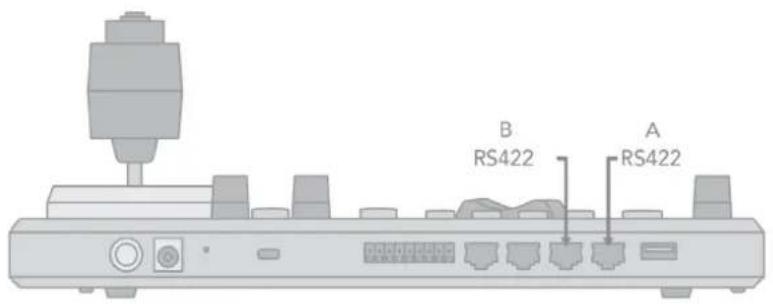
Adjusting Image Parameters
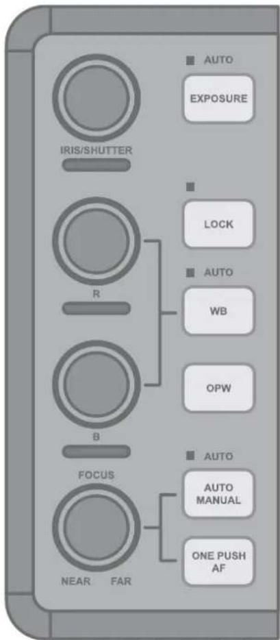
The following image parameters can be set/adjusted by using the Image Adjustment Panel. The knobs are velocity sensitive and responding naturally for incremental, as well as large adjustments.
Iris/Shutter
- Adjust manually by rotating the IRIS/SHUTTER knob.
•Auto-adjust by engaging the EXPOSURE button. - Toggle the exposure between Iris priority and Shutter priority by pressing the EXPOSURE button.
Red/Blue/White Balance
- Adjust Red or Blue values manually by rotating the R or B knob.
• Auto-adjust by engaging the WB button. - Engage One Push White Balance by pressing the ONE PUSH WB button.
Focus Near/Far
- Adjust manually by rotating the FOCUS knob (NEAR/FAR).
- Auto-adjust by engaging the ONE PUSH AF (Auto Focus) button.
Lock the image adjustment panel buttons by engaging the LOCK button.
Web Configuration Panel
The web configuration panel (BirdUI) allows you to alter key settings of PTZ Keyboard, such as Network settings, NDI settings, building API calls and applying firmware updates.
Access via web browser (URL)
PTZ Keyboard is configured to automatically receive a network IP address from the computer network via DHCP (Dynamic Host Configuration Protocol). Most corporate, education and home networks have a DHCP server present on the network to allow this to occur. Usually your Internet Router provides this.
If the Keyboard receives an IP address automatically from this server (DHCP), the IP address can be discovered in several ways, including BirdDog Central Lite available from here.
NOTE: Your computer will need to have 'Bonjour' services loaded in order to access the unit via it's user defined name. Apple devices come pre-installed with Bonjour, while Windows devices need a plugin available here.
Accessing PTZ Keyboard on a network without a DHCP server
Some standalone or private networks may not have a DHCP server. After 30 seconds of waiting for an automatically assigned IP address, the Keyboard will reassign to the designated fallback address (the default is 192.168.100.100).
In order to access the BirdUI on a network which is configured to a different subnet, change your computers IP address to match the Keyboard. Once you gain access to the BirdUI, choose your IP address to match the rest of the devices on your network.
For instructions on setting your computer's IP address, please consult your computer operating system manual or IT support resources.
Password Management
Once you direct your web browser to the BirdUI you will need to log in to change any settings.
Default Password
The BirdUI is secured by a user-selectable password. The default password is: birddog (one word, lower case).
Password Reset
To change the password simply login using the default password, navigate to the Network tab in the BirdUI, and select Change Password.
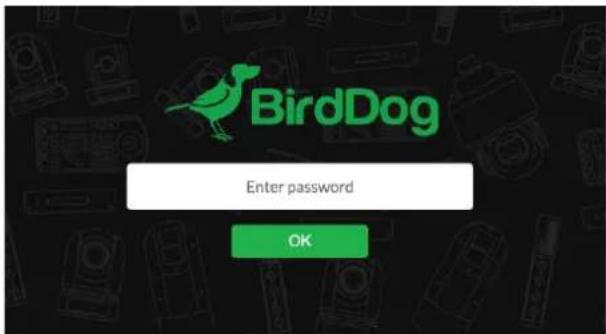
It is recommended to change this password in a network environment where the Keyboard is shared with other users (e.g. not private). By entering this password, the user is granted full access to the configuration settings and could interrupt a live program.
BirdUI Layout
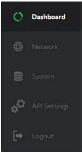
The BirdUI is organized into the following panels:
1. Dashboard
Overall view of important information such as the network connection type and video stream format and resolution.
2. Network
General network settings such as DHCP IP Address details, timeout fallback address and Keyboard network name, as well as NDI® specific network settings
3. System
System admin functions such as updates, password management, designation of group access and camera reboot.
4. API Settings
Here you can build custom API calls for remote control of your connected devices.
5. Logout
Click to logout from the BirdUI.
Dashboard
The Dashboard displays an overall view of important information.
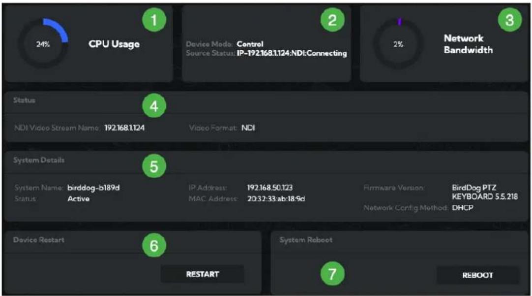
1. CPU Usage
Current computer system CPU utilization.
2. Device mode
The Device Mode is fixed at Control. Source IP adress and connection status is also shown.
3. Network Bandwidth
Network bandwidth consumption of the selected NDI ^® stream(s).
4. Status
a. NDI video stream name
b. Selected video format.
5. System Details.
a. Keyboard name.
b. IP and MAC Adress of the Keyboard and Network Configuration Method.
c. Online status of the Keyboard.
d. Current firmware version of the Keyboard.
6. Device Restart
Click this button to restart the NDI ^® stream. This may be necessary after changing NDI settings.
7. System Reboot
Click this button to reboot the unit after changing key network settings, the BirdDog name or after installing new firmware.
Network
Network Details
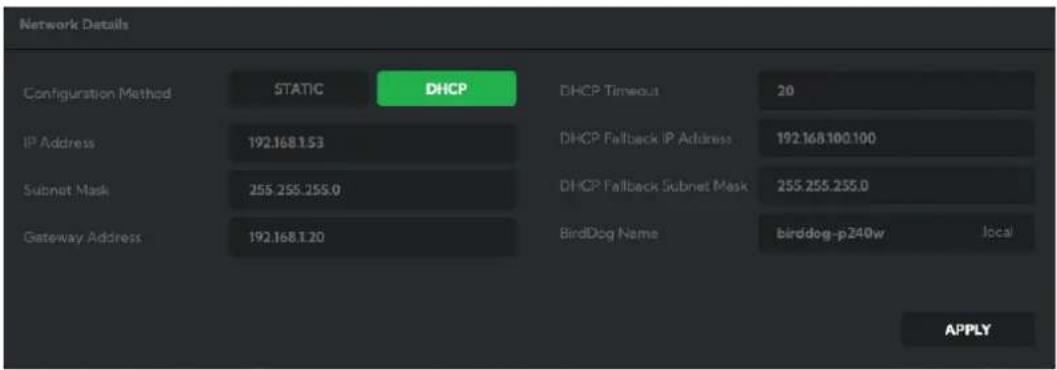
Most computer networks provide for both automatic and manual configuration of network devices and the PTZ Keyboard can accommodate both.
Configuration Method
Here you can set the network configuration to either DHCP (default) or Static. DHCP simplifies the management of IP addresses on networks. No two hosts can have the same IP address, so assigning them manually can potentially lead to errors. If your network is set up for DHCP, this is generally the best configuration to choose. If you do choose to go with a Static IP address, you'll need to add the IP Address, Subnet Mask and Gateway Address information according to the requirements of your network.
DHCP Timeout, Fallback IP address, Fallback Subnet Mask
You can set the timeout period during which Keyboard will wait for an assigned DHCP IP address. After this period, the Keyboard will default to the designated fallback IP address.
This can be useful if you use your Keyboard in other network environments. For example, if a DHCP server is available in your normal office or studio application, the Keyboard will use the DHCP supplied IP address. If you then use the Keyboard in another application without a DHCP server, your Keyboard will always default to the known fallover IP address.
NOTE: Do not set the fallback IP address the same as the Keyboard IP address. It is recommended to keep the fallback IP address.
IP Address Recovery
In the event that the PTZ Keyboard is not visible on the network, the network has changed, or the static IP address details have been lost, reset the BirdDog back to its default settings by following the factory reset procedure.
BirdDog Name
You can give your Keyboard a meaningful name to make identification easier when viewing NDI® sources on a receiver such as a TriCaster, vMix or Studio Monitor. Be sure to make the name unique, as no two devices on the network should have the same name. The name can be any combination of 'a-z, 0-9, and -'.
After renaming your Keyboard, navigate back to the Dashboard and click REBOOT DEVICE. The Keyboard will re-initialize and you'll be good to go.
Click in the BirdDog Name field to edit the name. The name must not include any special characters and can be any combination of a-z (lower case only), 0-9, and '-'
NDI Network Settings
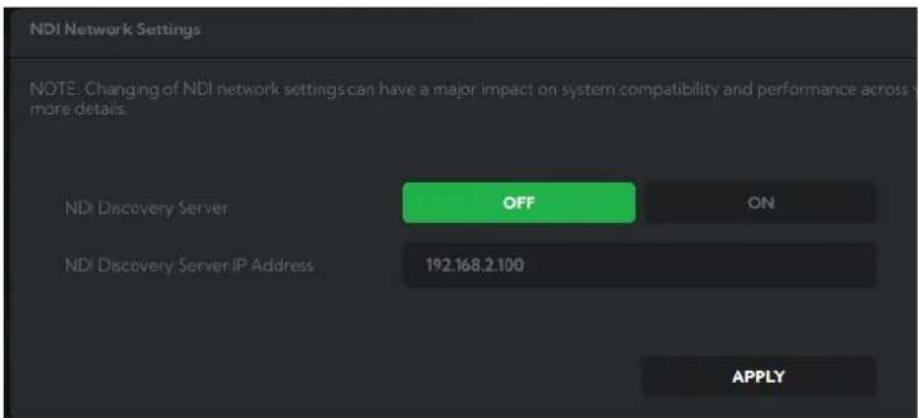
NDI Discovery
If you choose to use a NDI® Discovery Server, you can configure it in this tab. By default, NDI® utilizes mDNS (multicast Domain Name System) to create the zero configuration environment for discovery. Unless the network is specifically configured to not allow mDNS, NDI® sources will be discovered.
The NDI® discovery service is designed to replace the automatic discovery NDI® uses with a server that operates as an efficient centralized registry of NDI® sources that requires much less bandwidth. Multiple servers can be specified for failover redundancy. NDI® discovery server also helps with location of devices that reside on different subnets. The NDI® Discovery Server is available in the NDI 5.5 version of the free NDI Tools (C:\Program Files\NDI\NDI 5 Tools\Discovery\NDI Discovery Service.exe).
- If you are using one or more NDI® Discovery Servers, click the ON button.
- Enter a comma delimited list of the IP address(es) of your NDI® Discovery Server(s).
- Click the APPLY button to save your changes.
System
Password Settings

The Web UI is secured by a user-selectable password. The default password is birddog (one word, lower case).
You can change the password in the PASSWORD SETTINGS tab.
- Enter the current password.
- Enter the new password. It is recommended to change this password in a network environment where PTZ Keyboard is shared with other users (e.g. not private). By entering this password, the user is granted full access to the PTZ Keyboard configuration settings and could interrupt a live program.
- Confirm the new password and click APPLY.
System Update
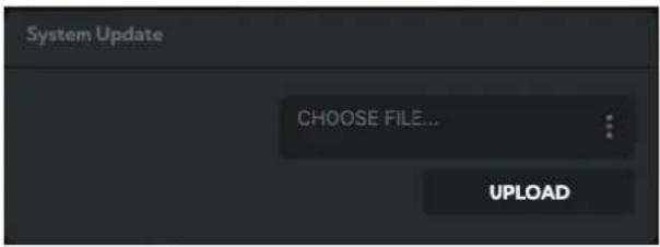
We are always adding new features and improving the performance of our products, so installing the latest firmware will provide you with the best user experience.
To upgrade the firmware, please download the firmware and follow the Firmware Upgrade Instructions located in your firmware folder.
System Reboot
Click this button to reboot the unit after changing key network settings, the BirdDog name or after installing new firmware.
Access Manager Configuration
Remote IP List
By default, NDI® devices are visible to each other only when they're on the same subnet. If you want visibility or control of a device on a different subnet, you need to add it's address manually as a Remote IP. You can upload and download Remote IP Lists for sharing with other devices. To upload a list:
- Click the CHOOSE FILE button to load your Remote IP List in UTF-8 encoded string format.
- Click the UPDATE button. Do not upload a blank list.
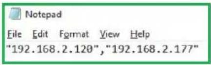
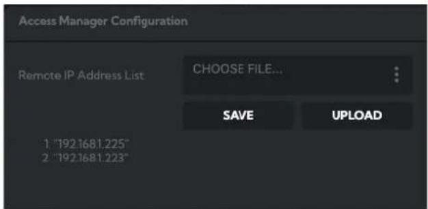
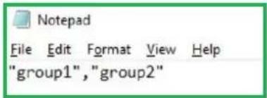
NDI Group List
Set the NDI® group list. NDI® groups allow you to restrict communication to only devices that belong to the same NDI® group. NDI® Groups can be very useful in larger environments to control visibility and access amongst various groups. You can upload and download group lists for sharing with other devices. Groups also need setting up in NDI Access Manager, available in NDI Tools.
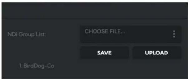
To upload a list:
- Click the CHOOSE FILE button to load your NDI® Group List in UTF-8 encoded string format.
- Click the UPDATE button. Do not upload a blank list.
P/T Control
The P/T Velocity Control allows selection of either a Superfine or Standard setting for the joystick. Superfine provides less coarsely quantised movement resulting in more precise control.

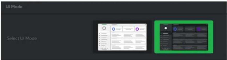
UI Mode
To improve legibility in different lighting conditions, you can choose between two different colour schemes for the BirdUI. Click on the image to change the scheme.
API Settings
RESTful API commands are accessible available by all BirdDog hardware, allowing you to remotely interact with your devices. When in API mode you can configure commands that can be assigned to the PTZ Keyboard Function Keys.
The APIs are sourced from the system API_Management.xlsx file which can be exported from the Add Profile panel, modified for your own requirements and re-imported.
The basic procedure is as follows:
- Configure the API command for the correct device.
- Assign the API command to a function key.
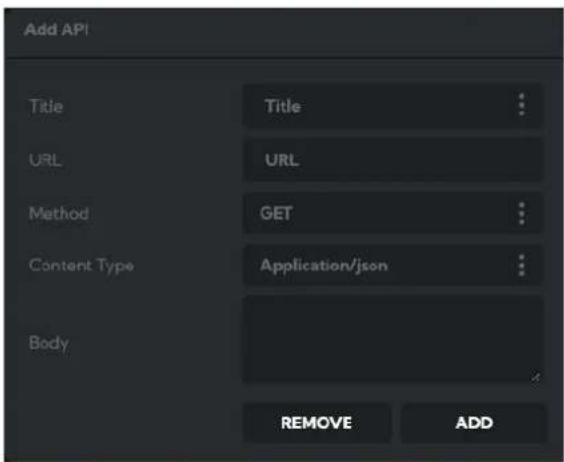
Add API
In this panel, you can build your API command by making selections from the following dropdown lists.
Title
Allows the selection of an API command from the displayed dropdown list or you can add your own Title and API.
URL
Displays the selected API and allows user input.
Method
Allows selection of the desired Method (POST or GET).
Content Type
Selects the Content Type as either JSON or plain text.
Body
Adds the Text string or JSON key:value pair.
Remove/Add buttons
These buttons edit the API_Management.xlsx spreadsheet. Click Remove to remove the displayed API command from the spreadsheet or click the Add button to add the currently displayed API command to the spreadsheet.
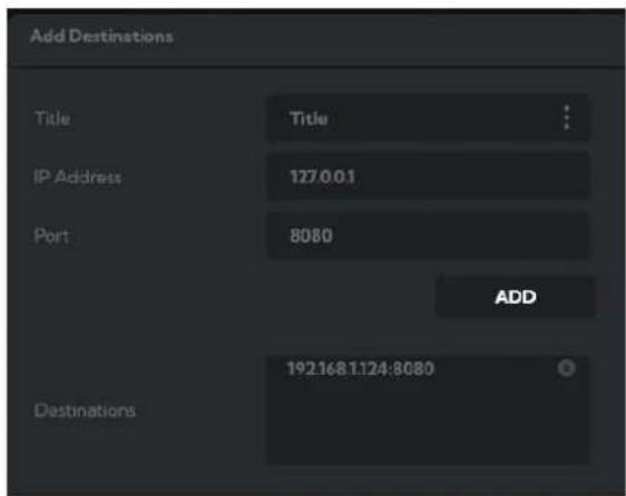
Add Destination
In this panel you configure the target device(s) for your API command.
Title
Editable name of the target device.
IP Address
Target device IP address.
Port
Target device listening port.
Destinations
After setting the above target device parameters, click the Add button to add it to the Destinations list.
Add Profile
You can assign your API command to a Keyboard Function Key and import and export API configuration files.
![Add Profile a b c F1 RecallPreset1 P200 Import/Export IMPORT CONFIG. EXPORT CONFIG. F2 About P100 Profile [“Recall-Preset”:1] F3 Info P100 Response F4 Devicesettingsg P100 F5 EncodeTranspor P100 NdiOffSnSrcget P100 SAVE PROFILE](/content/2026/05/760187/images/288c95069e0ea5ebba7ba7b3898a656fcdee3add7d228c3337da79c5528a6e20.jpg)
a. Clicking the desired Function button will send the assigned API command (b) to the selected destination (c).
b. Selects one of the APIs from the Add API panel (as defined in the API_Management.xlsx file).
c. Selects one of the destinations defined in the Add Destinations panel.
Import/Export
Imports or Exports an API_Management.xlsx file. This is the file from which you select and edit API commands.
NOTE After importing the API_Management.xlsx file, you'll need to refresh the browser (Windows [F5]) to display the new file contents.
Profile
Saves the current configuration of the Function keys
Response
Displays the response of of the API request.
Function Mode

In this tab, choose whether the PTZ Keyboard Function Keys use the default function commands or operate in API mode. In API mode, you can program custom commands to control network devices.
API Example
In the example below, the F1 key is configured to recall Preset 1 from the connected P200. The P200 is at address '192.168.100.21:8080'.
![Add API Title RecallPreset1 URL /recall Method POST Content Type Application/json ["Preset": "Preset-1"] Body REMOVE ADD Add Destinations Title P200 IP Address 192.168.100.21 Port 8080 ADD Destinations 192.168.100.22:8080 192.168.100.21:8080 Add Profile F1 RecallPreset1 P200 F2 About P100 F3 Info P100 F4 Devicesettingsg P100 F5 EncodeTranspor P100 F6 NdiOffSnSrcget P100 Import/Export Profile ['Recall-Preset': '1'] Response IMPORT CONFIG. EXPORT CONFIG. SAVE PROFILE](/content/2026/05/760187/images/02f3f449b6701af1ec71a13fe7174666f73330c43f5491a6befb095326422d19.jpg)
Using Other Control Protocols
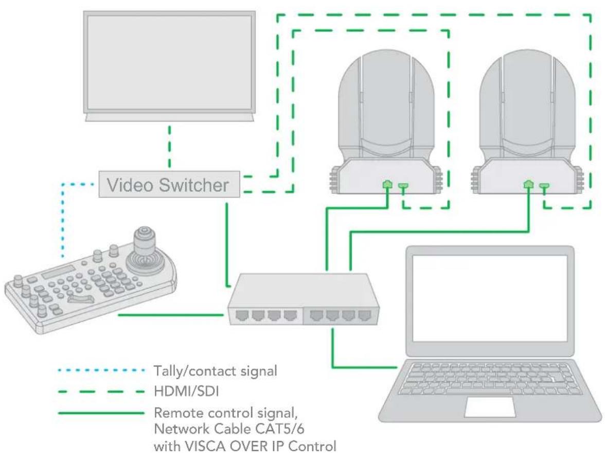
Use VISCA OVER IP Control
IP connection -> using VISCA OVER IP control protocol -> with a Visca Over IP ready camera.
flowchart
graph TD
    A["Video Switcher"] --> B["Remote control signal, Network Cable CAT5/6 with VISCA OVER IP Control"]
    B --> C["Tally/contact signal"]
    B --> D["HDMI/SDI"]
    B --> E["Laptop"]
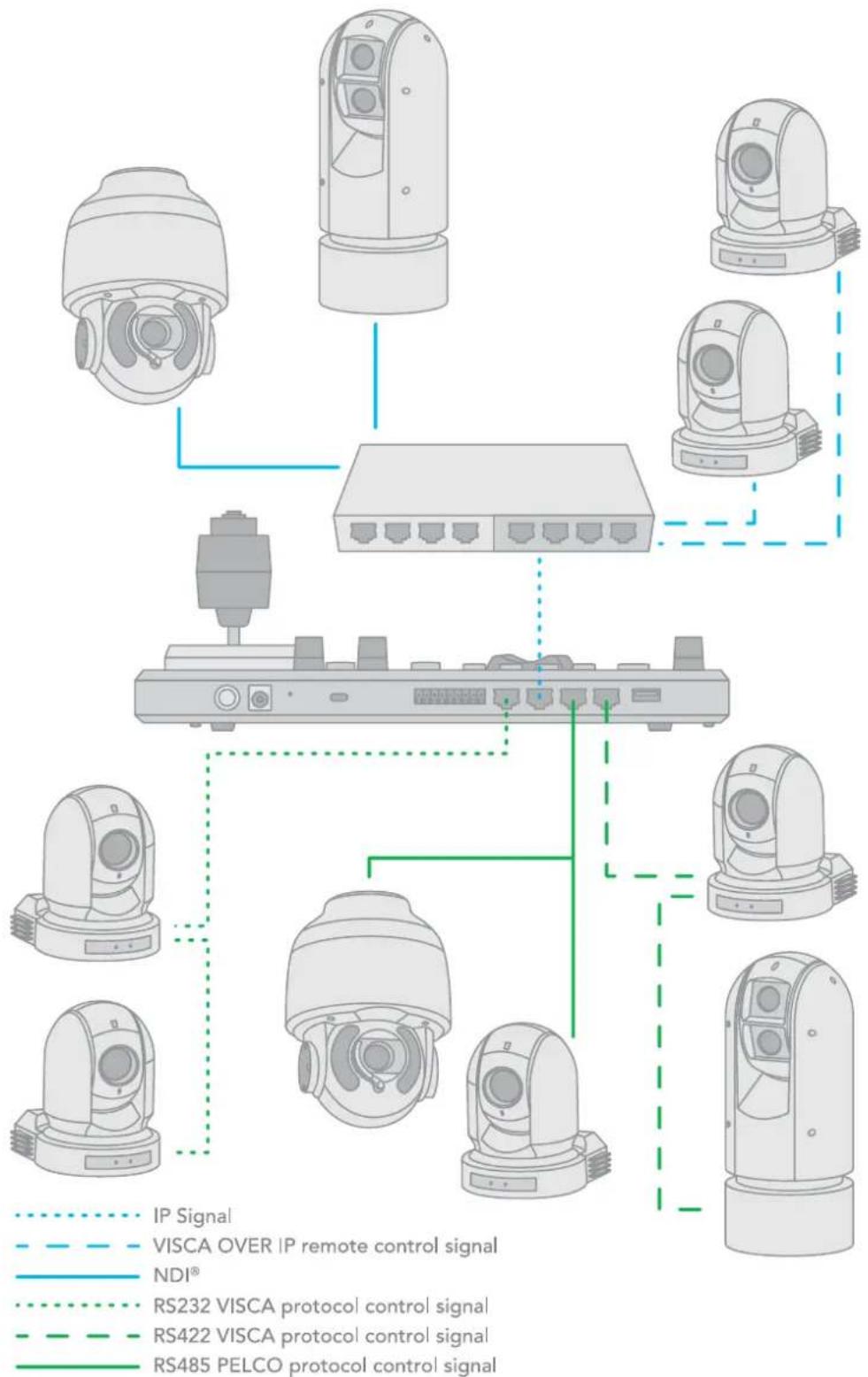
Cross-Protocol Mix Control
Using VISCA, PELCO, VISCA OVER IP, NDI® in a single system.
flowchart
graph TD
    A["Camera 1"] --> B["Switch"]
    C["Camera 2"] --> B
    D["Camera 3"] --> B
    E["Camera 4"] --> B
    F["Camera 5"] --> B
    G["Camera 6"] --> B
    H["Camera 7"] --> B
    I["Camera 8"] --> B
    J["Camera 9"] --> B
    K["Camera 10"] --> B
    L["Camera 11"] --> B
    M["Camera 12"] --> B
    N["Camera 13"] --> B
    O["Camera 14"] --> B
    P["Camera 15"] --> B
    Q["Camera 16"] --> B
    R["Camera 17"] --> B
    S["Camera 18"] --> B
    T["Camera 19"] --> B
    U["Camera 20"] --> B
    V["Camera 21"] --> B
    W["Camera 22"] --> B
    X["Camera 23"] --> B
    Y["Camera 24"] --> B
    Z["Camera 25"] --> B
    AA["Camera 26"] --> B
    AB["Camera 27"] --> B
    AC["Camera 28"] --> B
    AD["Camera 29"] --> B
    AE["Camera 30"] --> B
    AF["Camera 31"] --> B
    AG["Camera 32"] --> B
    AH["Camera 33"] --> B
    AI["Camera 34"] --> B
    AJ["Camera 35"] --> B
    AK["Camera 36"] --> B
    AL["Camera 37"] --> B
    AM["Camera 38"] --> B
    AN["Camera 39"] --> B
    AO["Camera 40"] --> B
    AP["Camera 41"] --> B
    AQ["Camera 42"] --> B
    AR["Camera 43"] --> B
    AS["Camera 44"] --> B
    AT["Camera 45"] --> B
    AU["Camera 46"] --> B
    AV["Camera 47"] --> B
    AW["Camera 48"] --> B
    AX["Camera 49"] --> B
    AY["IP Signal"] -.-> X
    AZ["VISCA OVER IP remote control signal"] -.-> X
    BA["NDI®"] -.-> X
    BB["RS232 VISCA protocol control signal"] -.-> X
    BC["RS422 VISCA protocol control signal"] -.-> X
    BD["RS485 PELCO protocol control signal"] -.-> X
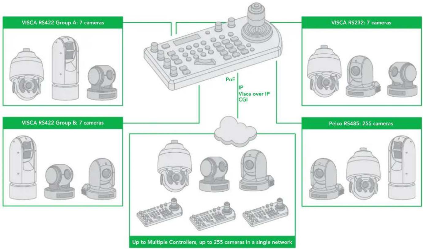
The Keyboard features cross protocol mix-control with RS232/RS422 and IP in one single system.
flowchart
graph TD
    A["VISCA RS422 Group A: 7 cameras"] --> B["IP Visca over IP CGI"]
    C["VISCA RS232: 7 cameras"] --> B
    D["VISCA RS422 Group B: 7 cameras"] --> B
    E["Pelco RS485: 255 cameras"] --> B
    B --> F["Up to Multiple Controllers, up to 255 cameras in a single network"]
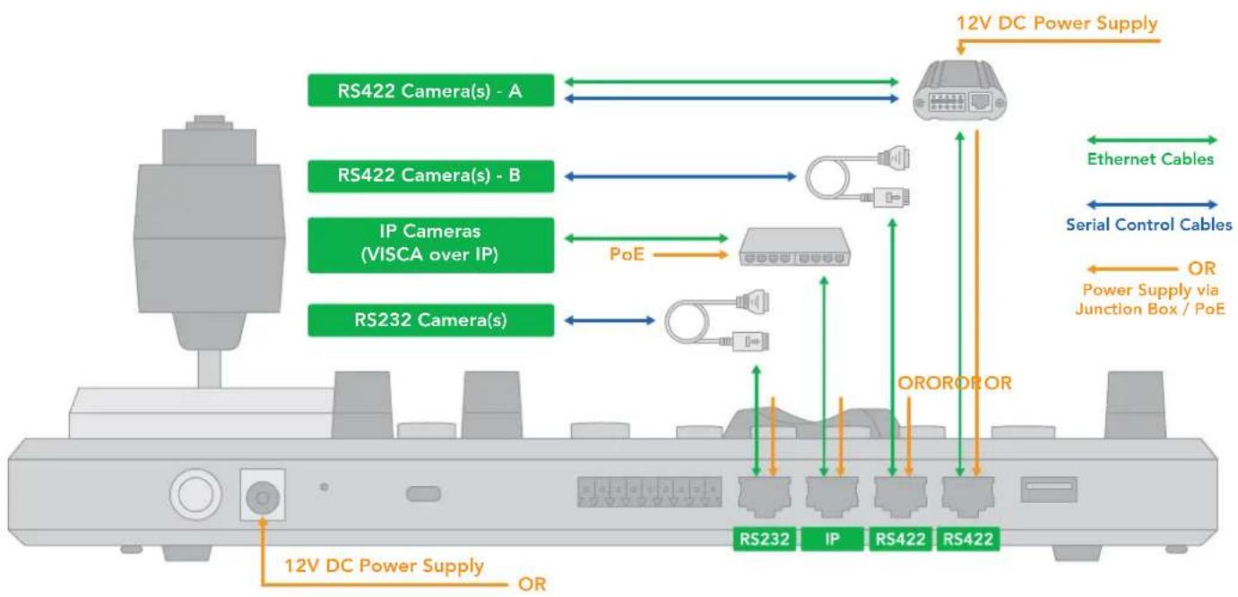
Cross Protocol Mix Control
flowchart
graph TD
    A["RS422 Camera(s) - A"] <--> B["12V DC Power Supply"]
    C["RS422 Camera(s) - B"] <--> D["IP Cameras (VISCA over IP)"]
    E["RS232 Camera(s)"] <--> F["12V DC Power Supply"]
    G["RS232"] --> H["IP"]
    I["RS422"] --> J["12V DC Power Supply"]
    K["OR"] --> L["OROROR"]
    M["Ethernet Cables"] --> N["Serial Control Cables"]
    O["Power Supply via Junction Box / PoE"] --> P["OR"]
When the junction box is powered, it will provide power to the Keyboard via any port that it is connected to i.e., RS232, IP, RS422(A), RS422(B).
Therefore, no additional power supply is required for the Keyboard if a powered junction box is used.
NOTE: Regarding Serial Control protocols (RS422/RS485 and RS232):
- When controlling only RS232 cameras, the Keyboard can control a total of 7 RS232 cameras.
- When controlling RS422 and RS232 cameras simultaneously, the Keyboard can control a total of 7 RS232 and RS422 cameras.
- When controlling only RS422 cameras, the Keyboard can control up to 14 RS422 cameras (2 daisy chains of 7).
- When controlling only RS485 cameras, the Keyboard can control up to 255 RS485 cameras.
The Keyboard is capable of simultaneously controlling up to 255 cameras, between mixed protocols (RS422, RS232, and IP).
Serial Port Connection
The controller supports serial RS232/RS422 and IP Cross protocol mix-control. It allows you to use RS232/RS422/IP control on one controller to control cameras (Protocol support: VISCA, PELCO D/P, VISCA over IP, CGI*) in a single system. NOTE: Daisy chain connection of multiple cameras does not apply to BirdDog P100, P110 and P120 cameras.
RS232 Connection
Use for the controller with a non-BirdDog camera connection.
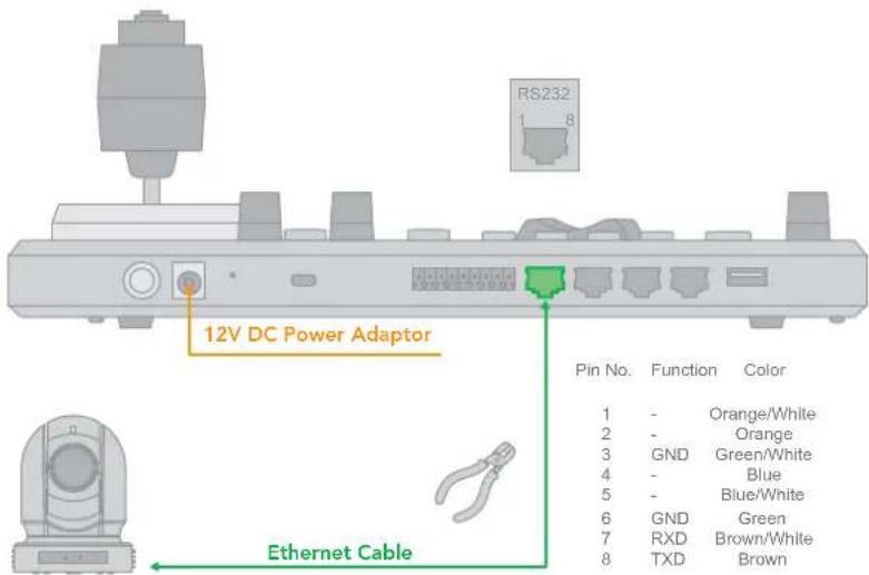
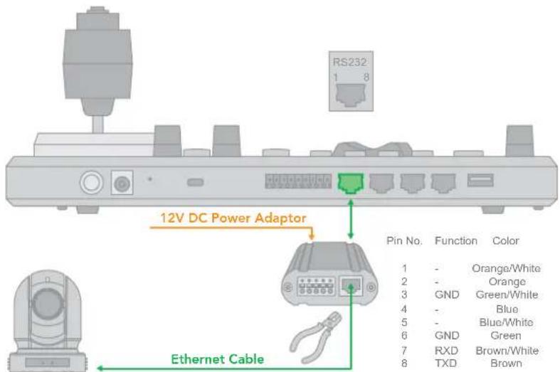
- RS232 connection using a network cable (follow the T-568B standard pinout at the Keyboard):
a. 1 to 1 connection – follow the pinout for the RS232 port on the Keyboard using CAT5e/6 cable to make a suitable cable for controlling your camera.
b. Use the Junction Box for a 1 to 1 connection – follow the pinout for the RS232 port on the Keyboard and Junction Box using CAT5e/6 cable (follow T-568B standard pinout between the Keyboard and Junction Box) to make a suitable cable for controlling your camera via the Junction Box.
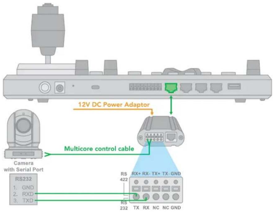
- RS232 connection using a multicore control cable.
RS232 connection -> via the Junction Box -> camera with a RS232 Serial Port.
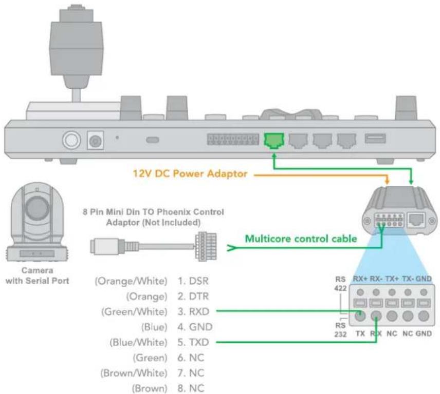
- RS232 connection with the camera having an 8-Pin Mini Din RS232 connector.
RS232 connection -> via the Junction Box -> camera with an 8-Pin MIni Din RS232 serial connector.
- RS232 daisy chain multiple camera connection.
RS232 daisy chain connection -> via the Junction Box -> camera with an RS232 Serial Port.
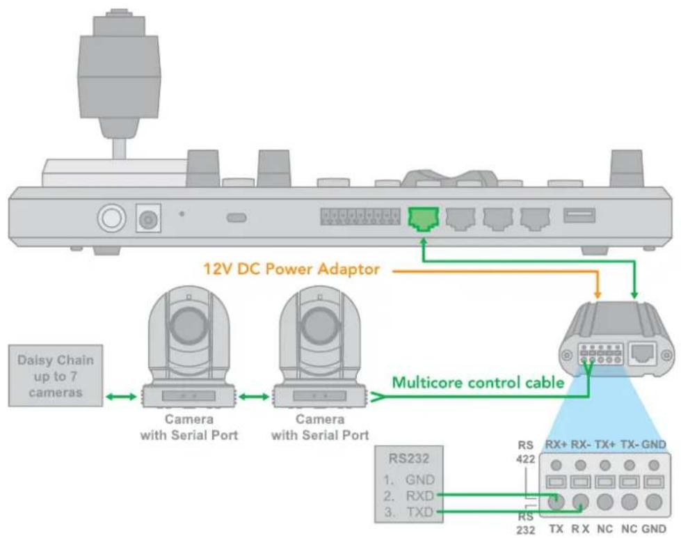
flowchart
graph TD
    A["12V DC Power Adaptor"] --> B["Daisy Chain up to 7 cameras"]
    B --> C["Camera with Serial Port"]
    C --> D["Camera with Serial Port"]
    D --> E["Multicore control cable"]
    E --> F["RS232"]
    F --> G["RS 422"]
    F --> H["RS 232"]
    G --> I["TX RX NC NC GND"]
    H --> J["TX RX NC NC GND"]
- RS232 connection using an RJ45 to Phoenix connector adaptor.
RS232 daisy chain connection -> using an RJ45 to Phoenix connector adaptor (not included).
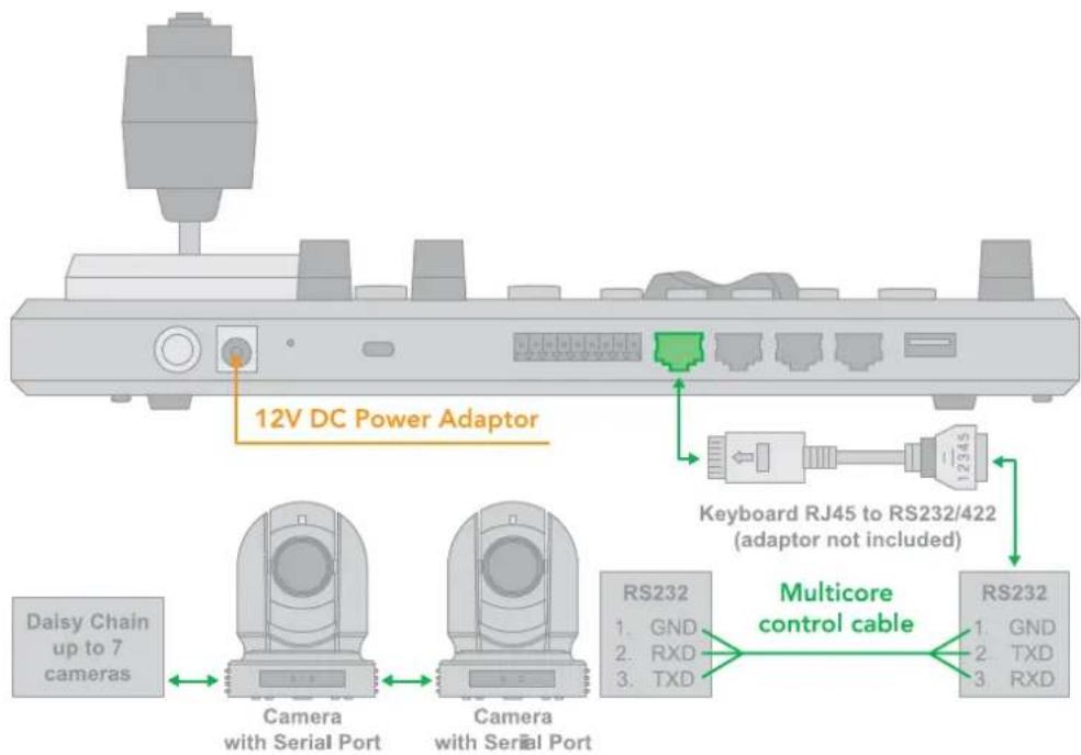
RS422 Connection
Use for the controller with non-BirdDog camera connection. For BirdDog camera connection see the separate section following.
Follow the diagrams below for the following options:
- RS422 connection using a network cable (follow the T-568B standard pinout at the Keyboard):
a. 1 to 1 connection - follow the pinout for the RS422 port on the Keyboard to use CAT5e/6 cable to make a suitable cable for controlling your camera.

b. Use the Junction Box for a 1 to 1 connection - follow the pinout for the RS422 port on the Keyboard and Junction Box to use CAT5e/6 cable (follow T-568B standard pinout between the Keyboard and Junction Box) to make a suitable cable for controlling your camera via the Junction Box.
RS422 connection -> via the Junction Box -> camera with a R422 Serial connector.
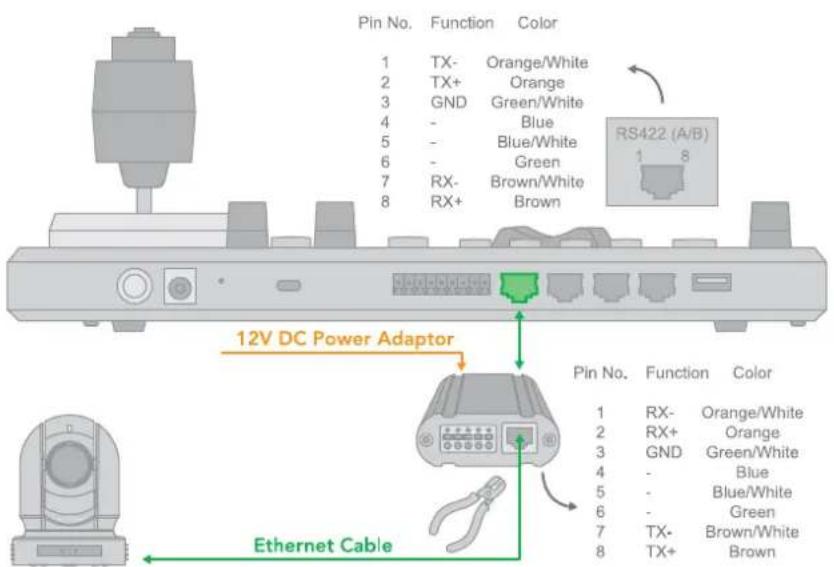
- RS422 connection using a multicore control cable.
RS422 connection -> via the Junction Box -> camera with an RS422 serial connector.
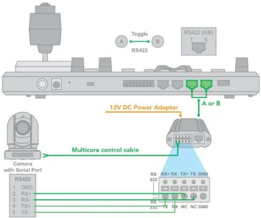
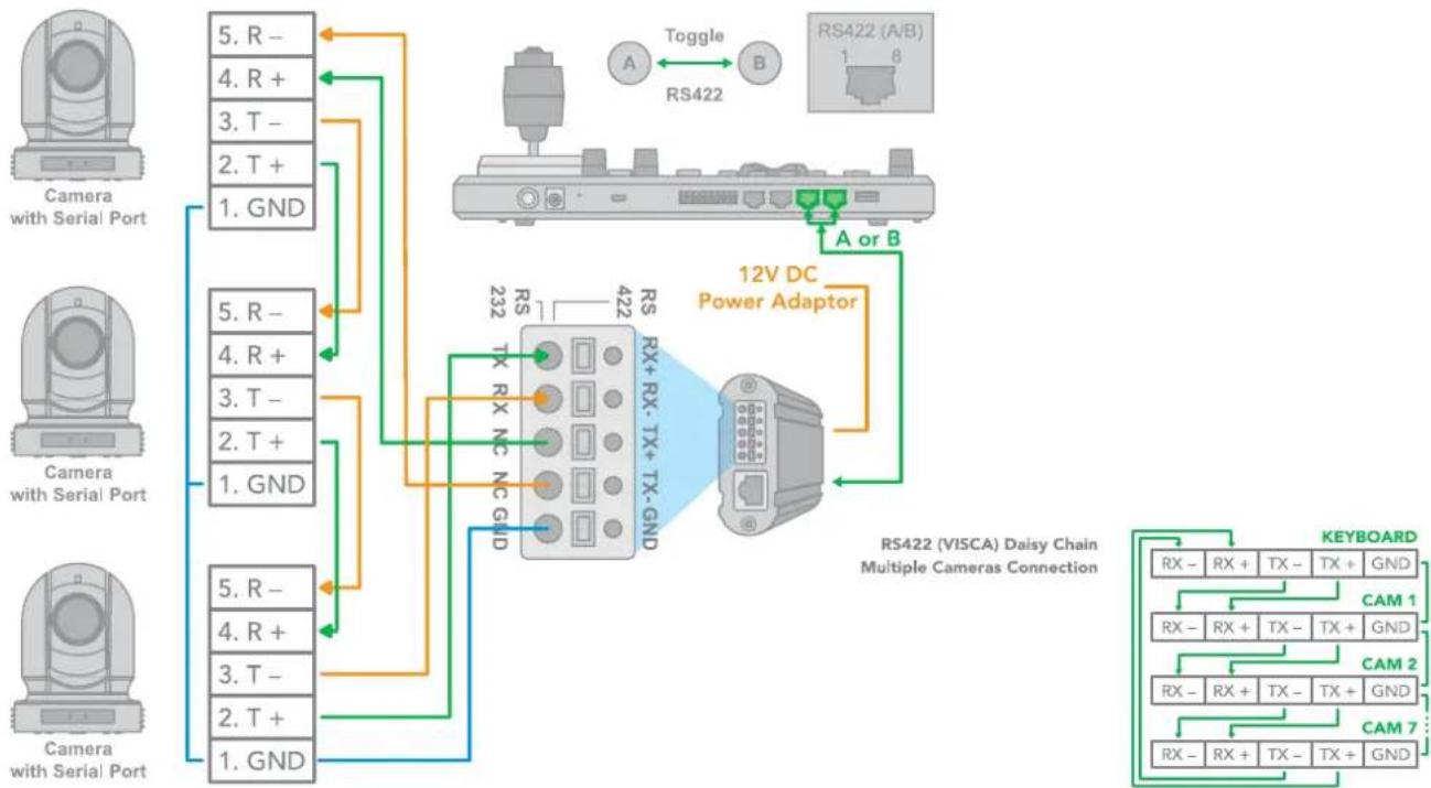
- RS422 daisy chain multiple camera connection
RS422 daisy chain connection -> via the Junction Box -> camera with a RS422 Serial Port.
Multicore control cable
flowchart
graph TD
    A["Camera with Serial Port"] -->|5. R - 4. R + 3. T - 2. T + 1. GND| B["RS422 (A/B)"]
    C["Camera with Serial Port"] -->|5. R - 4. R + 3. T - 2. T + 1. GND| D["RS422 (VISCA) Daisy Chain Multiple Cameras Connection"]
    E["Camera with Serial Port"] -->|5. R - 4. R + 3. T - 2. T + 1. GND| F["RS422 (A/B)"]
    B -->|A or B| G["RS422 (A/B)"]
    D -->|A or B| H["RS422 (A/B)"]
    F --> I["RS422 (A/B)"]
    G --> J["RS422 (A/B)"]
    H --> K["RS422 (A/B)"]
    style A fill:#f9f,stroke:#333
    style C fill:#f9f,stroke:#333
    style E fill:#f9f,stroke:#333
    style B fill:#ccf,stroke:#333
    style D fill:#ccf,stroke:#333
    style F fill:#ccf,stroke:#333
    style G fill:#ccf,stroke:#333
    style H fill:#ccf,stroke:#333
    style I fill:#ccf,stroke:#333
    style J fill:#ccf,stroke:#333
    style K fill:#ccf,stroke:#333
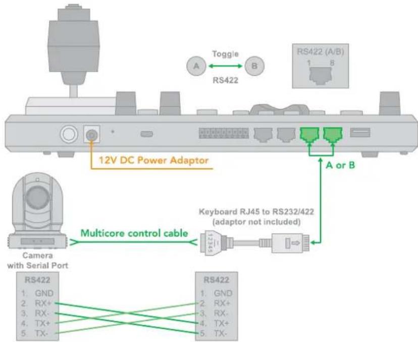
- RS422 1 to 1 connection using an RJ45 to Phoenix connector adaptor (not included) RS422 connection -> use an RJ45-RS422 adapter -> camera with an RS422 Serial Port.
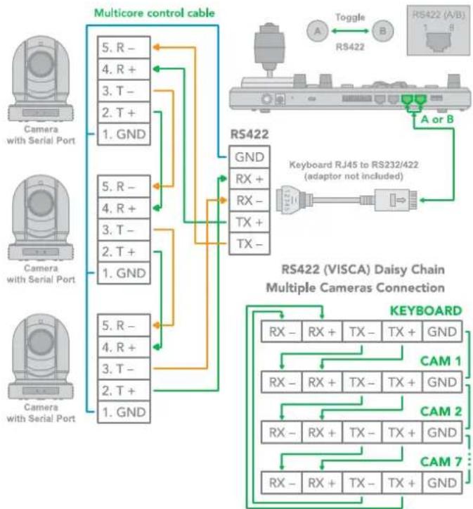
- RS422 daisy chain connection using an RJ45 to Phoenix connector adaptor (not included). RS422 daisy chain connection -> via RJ45 to RS422/232 adaptor -> camera with an RS422 Serial Port.
flowchart
graph TD
    A["RS422 (A/B)"] -->|Toggle| B["RS422"]
    B --> C["RS422 (VISCA) Daisy Chain Multiple Cameras Connection"]
    C --> D["RS422"]
    D --> E["RS422 (VISA) Daisy Chain Multiple Cameras Connection"]
    E --> F["RS422 (VISA) Daisy Chain Multiple Cameras Connection"]
    style A fill:#f9f,stroke:#333
    style B fill:#ccf,stroke:#333
    style C fill:#cfc,stroke:#333
    style D fill:#fcc,stroke:#333
    style E fill:#cff,stroke:#333
RS485 Connection
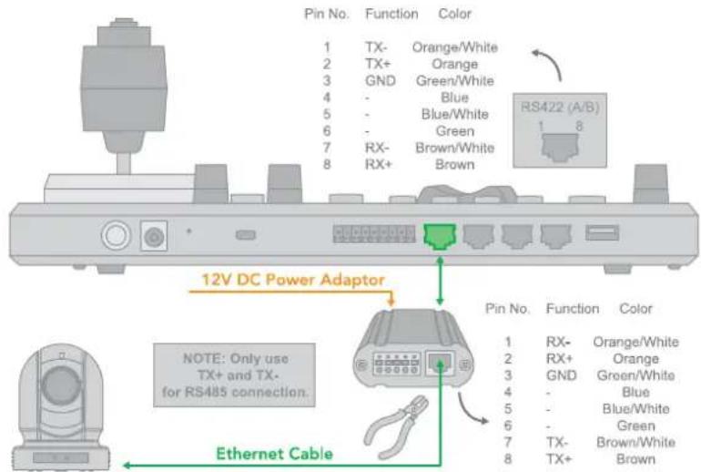
Use for the controller with a non-BirdDog camera. Follow the diagrams below for the following options:
- RS485 connection using a network cable (follow the T-568B standard pinout at the Keyboard end):
a. 1 to 1 connection – follow the pinout for the RS485 port on the Keyboard to use CAT5e/6 cable to make a suitable cable for controlling your camera.
NOTE: Use the RS422 ports for an RS485 connection.
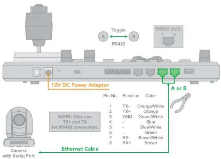
b. Use the Junction Box for a 1 to 1 connection – follow the pinout for the RS485 port on the Keyboard and the Junction Box to use CAT5e/6 cable (follow the T-568B standard pinout between the Keyboard and Junction Box) to make a suitable cable for controlling your camera via the Junction Box.
RS485 connection -> via the Junction Box -> camera with an RS485 Serial Port.
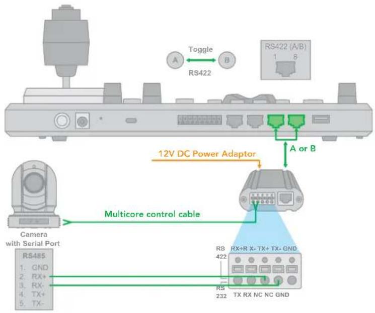
- RS485 connection using a multicore control cable.
RS485 connection -> via the Junction Box -> camera with an RS485 Serial Port.
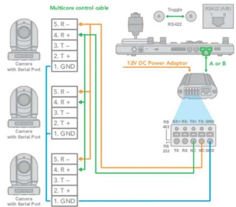
- RS485 daisy chain multiple camera connection.
RS485 daisy chain connection -> via the Junction Box -> camera with an RS485 Serial Port.
flowchart
graph TD
    A["Camera with Serial Port"] -->|5. R - 4. R + 3. T - 2. T + 1. GND| B["12V DC Power Adaptor"]
    C["Camera with Serial Port"] -->|5. R - 4. R + 3. T - 2. T + 1. GND| B
    D["Camera with Serial Port"] -->|5. R - 4. R + 3. T - 2. T + 1. GND| B
    B --> E["RS422 (A/B) 1-8"]
    B --> F["RS232 RX+RX-TX+TX-GND"]
    B --> G["RS422 TX RX NC NC GND"]
    style A fill:#f9f,stroke:#333
    style C fill:#f9f,stroke:#333
    style D fill:#f9f,stroke:#333
    style B fill:#ccf,stroke:#333
    style E fill:#cfc,stroke:#333
    style F fill:#cfc,stroke:#333
    style G fill:#cfc,stroke:#333
flowchart
graph TD
    A["RS485 (PELCO P/D) Multiple Cameras Connection"] --> B["CAM 1"]
    B --> C["RX - RX + TX - TX + GND"]
    B --> D["CAM 2"]
    D --> E["RX - RX + TX - TX + GND"]
    B --> F["CAM 3"]
    F --> G["RX - RX + TX - TX + GND"]
    B --> H["CAM 255"]
    H --> I["RX - RX + TX - TX + GND"]
    H --> J["PELCO P/D KEYBOARD"]
    J --> K["TXD IN- | TXD IN +"]
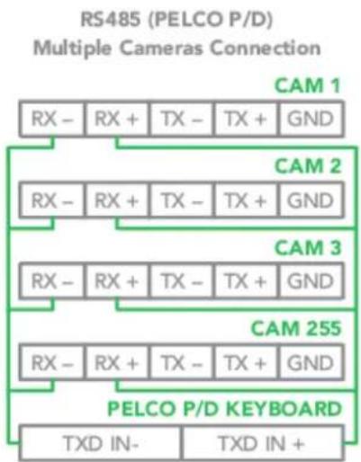
- RS485 daisy chain connection using RJ45 to Phoenix connector adaptor (not included). RS485 daisy chain connection – via a RJ45 to RS422 Adaptor – camera with an RS485 Serial Port.

flowchart
graph TD
    A["Camera with Serial Port"] -->|1. GND| B["RS485"]
    A -->|2. T+| B
    A -->|3. T-| B
    A -->|4. R+| B
    A -->|5. R-| B
    B --> C["RS485 (PELCO P/D) Multiple Cameras Connection"]
    C --> D["CAM 1: RX - RX + TX - TX + GND"]
    C --> E["CAM 2: RX - RX + TX - TX + GND"]
    C --> F["CAM 3: RX - RX + TX - TX + GND"]
    C --> G["CAM 255: RX - RX + TX - TX + GND"]
    G --> H["PELCO P/D KEYBOARD: TXD IN- & TXD IN +"]
    I["RS422 (A/B): Toggle"] --> J["RS422"]
    K["RS485"] --> L["Keyboard RJ45 to RS232/422 (adaptor not included)"]
    M["Camera with Serial Port"] --> N["RS485 (PELCO P/D) Multiple Cameras Connection"]
    O["Camera with Serial Port"] --> P["RS485 (PELCO P/D) Multiple Cameras Connection"]
Tally Light GPI I/O Connection
GPI Connection with RS422 VISCA Control Connection
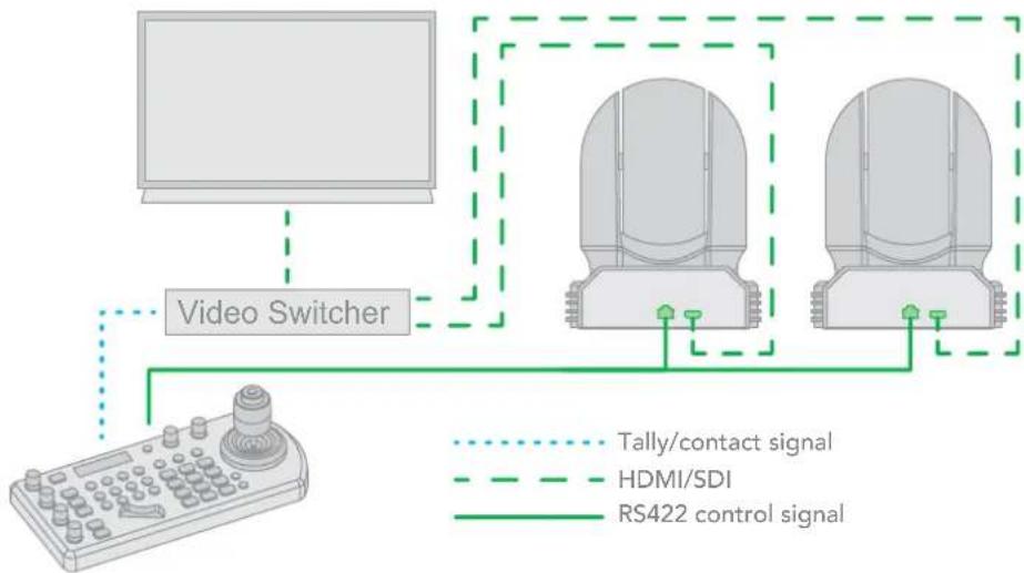
flowchart
graph TD
    A["Video Switcher"] --> B["Tally/contact signal"]
    A --> C["HDMI/SDI"]
    A --> D["RS422 control signal"]
    B --> E["Main Display"]
    C --> F["Main Display"]
    D --> G["Main Display"]
GPI Connection with VISCA OVER IP Control Connection
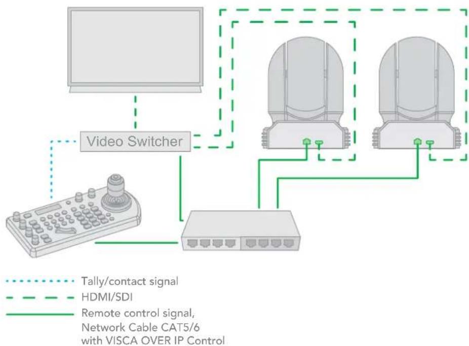
flowchart
graph TD
    A["Video Switcher"] --> B["Tally/contact signal"]
    A --> C["HDMI/SDI"]
    A --> D["Remote control signal, Network Cable CAT5/6 with VISCA OVER IP Control"]
    A --> E["Network Cable CAT5/6 with VISCA OVER IP Control"]
    A --> F["Network Cable CAT5/6 with VISCA OVER IP Control"]
    A --> G["Network Cable CAT5/6 with VISCA OVER IP Control"]
    A --> H["Network Cable CAT5/6 with VISCA OVER IP Control"]
    A --> I["Network Cable CAT5/6 with VISCA OVER IP Control"]
    A --> J["Network Cable CAT5/6 with VISCA OVER IP Control"]
    A --> K["Network Cable CAT5/6 with VISCA OVER IP Control"]
    A --> L["Network Cable CAT5/6 with VISCA OVER IP Control"]
    A --> M["Network Cable CAT5/6 with VISCA OVER IP Control"]
    A --> N["Network Cable CAT5/6 with VISCA OVER IP Control"]
    A --> O["Network Cable CAT5/6 with VISCA OVER IP Control"]
    A --> P["Network Cable CAT5/6 with VISCA OVER IP Control"]
    A --> Q["Network Cable CAT5/6 with VISCA OVER IP Control"]
    A --> R["Network Cable CAT5/6 with VISCA OVER IP Control"]
    A --> S["Network Cable CAT5/6 with VISCA OVER IP Control"]
    A --> T["Network Cable CAT5/6 with VISCA OVER IP Control"]
    A --> U["Network Cable CAT5/6 with VISCA OVER IP Control"]
    A --> V["Network Cable CAT5/6 with VISCA OVER IP Control"]
    A --> W["Network Cable CAT5/6 with VISCA OVER IP Control"]
    A --> X["Network Cable CAT5/6 with VISCA OVER IP Control"]
    A --> Y["Network Cable CAT5/6 with VISCA OVER IP Control"]
    A --> Z["Network Cable CAT5/6 with VISCA OVER IP Control"]
Appendix
PTZ Keyboard Pinout
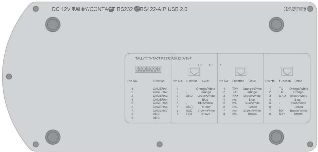
| IPTALLY/CONTACT RS232 RS422 (A/B) | ||||||||||
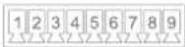 |  |  |  | |||||||
| Pin No. | Function | Pin No. | Function | Color | Pin No. | Function | Color | Pin No. | Function | Color |
| 1 | CAMERA1 | 1 | - | Orange/White | 1 | TX+ | Orange/White | 1 | TX- | Orange/White |
| 2 | CAMERA2 | 2 | - | Orange | 2 | TX- | Orange | 2 | TX+ | Orange |
| 3 | CAMERA3 | 3 | GND | Green/White | 3 | RX+ | Green/White | 3 | GND | Green/White |
| 4 | CAMERA4 | 4 | - | Blue | 4 | n/c | Blue | 4 | - | Blue |
| 5 | CAMERA5 | 5 | - | Blue/White | 5 | n/c | Blue/White | 5 | - | Blue/White |
| 6 | CAMERA6 | 6 | GND | Green | 6 | RX- | Green | 6 | - | Green |
| 7 | CAMERA7 | 7 | RXD | Brown/White | 7 | n/c | Brown/White | 7 | RX- | Brown/White |
| 8 | GND | 8 | TXD | Brown | 8 | n/c | Brown | 8 | RX+ | Brown |
| 9 | GND | |||||||||
PTZ Keyboard Dimensions
Unit: mm
Glossary
Domain
A domain contains a group of computers that can be accessed and administered with a common set of rules. Domain can also refer to the IP address of a website on the Internet.
DNS
DNS (Domain Name System) is a system used by the Internet and private networks to translate domain names into IP addresses.
mDNS
mDNS (Multicast DNS) refers to the use of IP multicast with DNS to translate domain names into IP addresses and provide service discovery in a network that does not have access to a DNS server.
Ethernet
Ethernet, standardized as IEEE 802.3, refers to a series of technologies used to connect computers and other devices to a LAN (Local Area Network) or wide area network (WAN).
Firmware
Firmware is a class of software held in non-volatile memory that provides the low-level control for a device's hardware.
Gigabit Ethernet (GigE)
An Ethernet capable of transmitting frames at a rate of a gigabit per second. A Gigabit capable Ethernet network is recommended for NDI® production workflows.
IP
IP (Internet Protocol) is the communications protocol for the Internet, many wide area networks (WANs), and most local area networks (LANs) that defines the rules, formats, and address scheme for exchanging datagrams or packets between a source computer or device and a destination computer or device.
LAN
LAN (Local Area Network) is a network that connects computers and devices in a room, building, or group of buildings. A system of LANs can also be connected to form a WAN (Wide Area Network).
Mbps
Mbps (Megabits per second) is a unit of measurement for data transfer speed, with one megabit equal to one million bits. Network transmissions are commonly measured in Mbps.
NDI®
NDI® (Network Device Interface) is a standard allowing for transmission of video using standard LAN networking. NDI® comes in two flavours, NDI® and NDI®|HX. NDI® is a variable bit rate, I-Frame codec that reaches rates of around 140Mbps at 1080p60 and is visually lossless. NDI®|HX is a compressed, long-GOP, H.264 variant that achieves rates around 12Mbps at 1080p60.
PELCO
PELCO is a camera control protocol used with PTZ cameras. See also VISCA.
PoE
Power over Ethernet.
Port
A port is a communications channel for data transmission to and from a computer on a network. Each port is identified by a 16-bit number between 0 and 65535, with each process, application, or service using a specific port (or multiple ports) for data transmission. Port can also refer to a hardware socket used to physically connect a device or device cable to your computer or network.
PTZ
Pan, tilt and zoom.
RJ45
A form of standard interface commonly used to connect computers onto Ethernet-based local area networks (LAN).
RS422, RS485, RS232
Physical layer, serial communication protocols.
Subnet
Subnet or subnetwork is a segmented piece of a larger network.
Tally
A system that indicates the on-air status of video signals usually by the use of a red illuminated lamp.
TCP
TCP (Transmission Control Protocol) is a network communications protocol.
UDP
UDP (User Datagram Protocol) is an alternative protocol to TCP that is used when reliable delivery of data packets in not required.
VISCA
VISCA is a camera control protocol used with PTZ cameras. See also PELCO.
WAN
WAN (Wide Area Network) is a network that spans a relatively broad geographical area, such as a state, region, or nation.
White Balance
White balance (WB) is the process of ensuring that white objects and by extension, all colour, in your video are rendered accurately. Without correct white balance, objects in your video display unrealistic color casts.

WELCOME TO THE FUTURE.
birddog.tv
hello@birddog.tv
- Table of Contents
- Keyboard Configuration 17
- Adding an NDI ® Camera to the Keyboard 21
- Adding non-NDI® Cameras to the Keyboard 21
- Interacting With Cameras 24
- Setting and Calling Presets 26
- Adjusting Image Parameters 27
- Web Configuration Panel 28
- BirdUI Layout....29
- Dashboard 30
- Network 31
- System 32
- API Settings....35
- Using Other Control Protocols 38
- Tally Light GPI I/O Connection 51
- Appendix 52
- Glossary 54
- Copyright
- Trademark Acknowledgement
- Important Information
- Legal Notice
- Warnings
- Regulatory Compliance
- FCC Part 15
- LVD/EMC Directive
- Welcome to BirdDog
- Using This Manual
- Tip
- First Step
- Firmware Upgrade
- We're Invested in Your Success
- Overview of the PTZ Keyboard
- Key Features
- Features
- Welcome to the Future
- What is NDI®?
- What's in the Box?
- Optional Accessories
- Getting Started With Your PTZ Keyboard
- Your PTZ Keyboard at a Glance
- LCD Screen and Navigation
- Camera Control
- Assign Keys
- Camera Image Adjustment
- Connections
- Power
- Joystick Calibration
- Network
- Camera Search
- You're Done!
- Pan Tilt Speed knob
- Call
- Zoom Speed knob
- IRIS / Shutter Adjustment for Exposure
- Manual Red Adjustment for White Balance
- Manual Blue Adjustment for White Balance
- Manual Focus
- One-Push Focus
- Focus Auto/ Manual Toggle
- OPW (One Push WB) For White Balance
- Assign Keys
- Zoom Seesaw
- BLC (Back Light Compensation)
- OSD Menu Button
- MON
- Alphanumeric Keypad
- CAM
- RS422 Group B Selection
- RS422 Group A Selection
- Joystick Button
- Keyboard Rear Panel
- Keyboard Screen
- Junction Box
- Powering the PTZ Keyboard
- Power Supply (included)
- PoE
- Junction Box (included)
- Connecting the PTZ Keyboard to Your network
- NDI® Connection
- Other Control Protocols
- Navigating the Menus
- P/T Speed Dial
- Zoom Speed Dial
- Keyboard Configuration
- Keyboard Setting Menu
- DHCP
- Static
- Button Light
- Function Key Assignment
- Factory Reset Options
- Factory Default
- Hardware and Network Reset
- Tally - GPI I/O
- Command Select
- Password Setting
- Joystick Zoom Setting
- Model Info
- Adding an NDI® Camera to the Keyboard
- Searching a Local Area Network (LAN)
- Adding Cameras Manually
- Adding non-NDI® Cameras to the Keyboard
- Manually adding cameras
- Adding a VISCA over IP Camera to the PTZ Keyboard
- Adding a camera manually from Local Area Network (LAN)
- Scanning the Local Network for Available VISCA over IP Cameras
- Adding VISCA over IP Cameras Under WAN Control
- At the Camera Location
- At the Keyboard Location
- Interacting With Cameras
- Options for Calling a Camera
- OR
- Controlling Cameras
- Engaging the Camera OSD Menu for non-IP Cameras
- Engaging the Camera OSD Menu for PELCO-D Cameras
- Using the Joystick to Control Cameras
- Joystick Movements
- NDI® Keyboard Router
- Setting and Calling Presets
- Creating Presets
- Calling Presets
- Resetting / Deleting Presets
- Dual RS422 Button A/B
- Adjusting Image Parameters
- Iris/Shutter
- Red/Blue/White Balance
- Focus Near/Far
- Web Configuration Panel
- Access via web browser (URL)
- Accessing PTZ Keyboard on a network without a DHCP server
- Password Management
- Default Password
- Password Reset
- BirdUI Layout
- Dashboard
- Network
- System
- API Settings
- Logout
- Dashboard
- CPU Usage
- Device mode
- Network Bandwidth
- Status
- System Details.
- Device Restart
- System Reboot
- Network Details
- Configuration Method
- DHCP Timeout, Fallback IP address, Fallback Subnet Mask
- IP Address Recovery
- BirdDog Name
- NDI Network Settings
- NDI Discovery
- System
- Password Settings
- System Update
- System Reboot
- Access Manager Configuration
- Remote IP List
- NDI Group List
- To upload a list:
- P/T Control
- UI Mode
- API Settings
- Add API
- Title
- URL
- Method
- Content Type
- Body
- Remove/Add buttons
- Add Destination
- IP Address
- Port
- Destinations
- Add Profile
- Import/Export
- Profile
- Response
- Function Mode
- API Example
- Using Other Control Protocols
- Use VISCA OVER IP Control
- Cross-Protocol Mix Control
- Cross Protocol Mix Control
- Serial Port Connection
- RS232 Connection
- RS422 Connection
- RS485 Connection
- Tally Light GPI I/O Connection
- Appendix
- PTZ Keyboard Pinout
- PTZ Keyboard Dimensions
- Glossary
- Domain
- DNS
- mDNS
- Ethernet
- Firmware
- Gigabit Ethernet (GigE)
- IP
- LAN
- Mbps
- NDI®
- PELCO
- PTZ
- RJ45
- RS422, RS485, RS232
- Subnet
- Tally
- TCP
- UDP
- VISCA
- WAN
- White Balance
Brand : BirdDog
Model : PTZ Keyboard
Category : Remote control