
L30G (2016) - Hydraulic Excavator VOLVO - Free user manual and instructions
Find the device manual for free L30G (2016) VOLVO in PDF.


| Product Type | Compact Wheel Loader |
| Model | L30G (2016) |
| Engine Model | Volvo D3.3H / D3.3M (4-cylinder turbo diesel) |
| Engine Power (Net) | 55.4 kW (74.3 hp) |
| Emission Level | EU Stage IIIB / US Tier 4f |
| Operating Weight | 6,000 kg (13,228 lb) |
| Max Machine Weight | 6,650 kg (14,661 lb) |
| Fuel Tank Capacity | 84 liters (22 US gal) |
| Transmission | Infinitely variable hydrostatic, 2-speed (0-20 km/h standard, 0-30 km/h high-speed) |
| Steering | Articulated frame, hydrostatic, ±40° angle |
| Hydraulic System | Open centre, pilot-operated main control valve |
| Hydraulic Cycle Times (Lift Up) | 6.0 seconds (empty bucket) |
| Hydraulic Cycle Times (Tipping) | 1.5 seconds (empty bucket) |
| Brake System | Hydraulic inching pedal; service brakes: drum (standard) or disc (high-speed); parking brake: mechanical drum |
| Operator Cab | ROPS/FOPS approved, heating/ventilation, optional AC |
| Sound Pressure Level (Cab) | 75 dB(A) (ISO 6396) |
| Sound Power Level (External) | 101 dB(A) (guaranteed) |
| Bucket Capacity (General Purpose) | 1.0 - 1.2 m³ (1.3 - 1.6 yd³) heaped |
| Static Tipping Load (Full Turn) | 3,700 kg (8,157 lb) with general purpose bucket |
| Standard Tire Size | 12.5 - 20 or 15.5 R25 L3 (multiple options) |
Frequently Asked Questions - L30G (2016) VOLVO
User questions about L30G (2016) VOLVO
0 question about this device. Answer the ones you know or ask your own.
Ask a new question about this device
Download the instructions for your Hydraulic Excavator in PDF format for free! Find your manual L30G (2016) - VOLVO and take your electronic device back in hand. On this page are published all the documents necessary for the use of your device. L30G (2016) by VOLVO.
USER MANUAL L30G (2016) VOLVO
natural_image
Illustration of a yellow front-end loader with front loadings, shown in front of a vehicle chassis (no text or symbols present)VOLVO
Volvo Construction Equipment
Ref. No. 21034367-5
2016.12 Volvo, Ecklsluca
English
The image is too blurry to recognize any text content.

Foreword
This operator's manual is intended as a guide for the correct use and maintenance of the machine. Read this manual carefully before you start and move the machine or before you carry out any preventive maintenance.
Keep this manual in the lockable storage compartment so that it is always available for easy reference. Replace it immediately if it is lost.
The operator's manual describes the applications for which the machine was primarily designed. It has been written to be valid on all markets. Therefore, please ignore any sections which do not relate to your machine or to the work that you do not perform with your machine.
NOTE!
If the manual covers more than one machine, the information relates to all machines unless otherwise specified.
NOTE!
There are two engine alternatives, D3.3H and D3.3M. Check the engine model on the engine and exhaust decal, see page 23. If the engine model is D3.3H, the engine is equipped with both a diesel oxidation catalyst (DOC) and a diesel particulate filter (DPF) and requires regeneration. If the engine model is D3.3M, the engine is only equipped with DOC and does not require regeneration. The information in this manual that only applies to one of the engine models is marked for this with a reference to either D3.3H or D3.3M.
When designing this machine, much time has been invested in achieving the best possible efficiency and safety. But accidents do happen, and most of them can be attributed to human error. A safety-conscious person and a well-maintained machine make up a reliable, powerful, and profitable combination. Therefore, read the safety instructions and follow them.
We constantly strive to develop and improve the efficiency of our products by making changes to their design. We reserve the right to make design modifications to the products even after they have been delivered. Also, we reserve the right to change data and equipment, as well as the service and maintenance instructions, without prior notice.
OPERATOR'S MANUAL
Table of contents
Presentation
Instrument panels
Other controls
Operating instructions
Operating techniques

Safety when servicing
Service and maintenance
Specifications
Alphabetical index
Ref. No. 20034361-E
Safety regulations
The machine operator is responsible for being aware of and complying with the relevant, legally prescribed, national and regional safety instructions. The safety instructions in this operator's manual are applicable as basic requirements, but national or local regulations that are more strict should be followed.

DANGER
The safety symbol combined with this signal word indicates a hazardous situation which, if not avoided, will result in death or serious injury. Danger is limited to the most extreme situations.

WARNING
The safety symbol combined with this signal word indicates a hazardous situation which, if not avoided, could result in death or serious injury.

CAUTION
The safety symbol combined with this signal word indicates a hazardous situation which, if not avoided, could result in moderate or minor injury.
NOTICE
Indicates a potentially hazardous situation which may result in machine damage.
NOTE!
Used in order to refer to installation, operating, or maintenance information which is important but not danger-related.
Get to know the capacity and limits of your machine!
Identification numbers
Make a note of the machine data below on this page in order to avoid any misunderstanding when ordering spare parts or making any enquiries by telephone or in writing.
| Manufacturer: Volvo Construction Equipment | GermanyGmbHMax-Plank-Straße 1 54329 Konz, Germany |
| Model/Type: | |
| Product identification number: | |
| Year of manufacture: |
Model-specific information
The information in the manual applies to all machine models unless otherwise stated.
– Standard version: 20 km/h.
– High-speed version: 30 km/h.
Contact information
Please send any comments about the Operator's Manual to
om@volvo.com

Table of contents
Foreword 1
Identification numbers ...... 3
Presentation 9
CE-marking, EMC-directive 15
Communication equipment, installation ..... 21
Safety components 22
Product plates 23
Information and warning decals 25
Instrument panels 31
Instrument panel, front 32
Display unit 43
Instrument panel, side 51
Other controls 54
Controls 54
Operator comfort 67
Climate control system 71
Operating instructions 77
Safety rules when operating 82
Measures before operating 92
Starting engine 93
Braking 97
Exhaust aftertreatment system 98
Stopping 112
Parking 113
Measures when getting stuck 115
Retrieving and towing 116
Transporting machine 119
Operating techniques 123
Eco driving 124
Whole-body vibrations 126
Working within dangerous areas 128
Attachments 132
Attachment brackets 135
Hydraulic function, 3rd and 4th ...... 139
Loading 141
Buckets 142
Pallet forks 150
Timber grapples 153
Salt sprayer 154
Special hydraulics 156
Material handling arm 157
Road sweeping (optional equipment) ..... 159
Lifting objects 160
Signalling diagram 162
Safety when servicing 164
Service position 165
Before service, read 168
Fire prevention 171
Handling hazardous materials 174
Handling line, tubes and hoses 179
Service and maintenance 180
Service points 186
Engine 187
Fuel system 188
Engine air cleaner 191
Cooling system 192
Electrical system 195
Brake system 198
Wheels 200
Cab 202
Windscreen wiper system 203
Air conditioning 204
Bucket teeth 206
Hydraulic system 208
Greasing 210
Lubrication and service chart 213
Specifications 218
Recommended lubricants 218
Fuel system 222
Service capacities and change intervals ..... 228
Engine 230
Electrical system 231
Transmission 237
Brake 238
Steering 239
Wheels 240
Cab 242
Hydraulic system 244
Machine weights 245
Dimensions 246
Service history 254
Alphabetical index 257

Presentation

natural_image
Side-view line drawing of a front-end loader (V1128538) with no visible text or symbols on the vehicle itself.V1128538
Intended use
The basic machine is intended to be used under normal conditions, that is, outdoors, above ground, up to 1,500 metres above sea level, off-road, for earthmoving operations, at an ambient temperature between -20 °C and +40 °C with only the operator in the cab. Conditions that deviate from this are also described in the Operator's Manual. For use on public roads the machine must be adapted according to governing national legislation.
If it is used for other purposes or in potentially dangerous environments, e.g., explosive and/or flammable environments or areas with dust containing asbestos, special safety regulations must be followed and the machine must be equipped for such use and handling. Contact the manufacturer/dealer for more information.
The machine is designed for a max. total weight (incl. equipment and attachments), see page 245. The max. weight applies when the machine is equipped for certain applications approved by Volvo. If the maximum weight is exceeded, safety is compromised. In addition, no manufacturer warranties will apply. However, always pay attention to national regulations for operating on public roads.
Operating underground
The need for ventilating the exhausts shall be checked before the machine is used in tunnels or other underground operations. Other legislation and rules may be applicable, such as national law and labour laws.
Environmental requirements
Be aware of the environment when operating and during service and maintenance of the machine. Always follow local and national environmental legislation applicable to all handling of the machine.
Frame
Articulating and oscillating joint concept. Front and rear frame designed for maximum ground clearance with rugged articulation joint bearings.
Engine
The machine is equipped with a straight four-cylinder, fourstroke, turbocharged diesel engine with fuel direct injection.
There are two engine alternatives depending on the type of engine exhaust aftertreatment system:
- D3.3H, with a diesel oxidation catalyst (DOC) and a diesel particulate filter (DPF), that requires regeneration.
- D3.3M, with a diesel oxidation catalyst (DOC), that does not require regeneration.
The engines for USA meet US Tier 4f and California Tier 4f. Engines for the EU meet EU's Stage IIIB emission requirements.
Exhaust aftertreatment system
There are two types of exhaust aftertreatment system depending on engine model, as follows.
Engine model D3.3H
The engine has an exhaust aftertreatment system (EATS) in the form of a diesel particulate filter (DPF) to minimize particles and nitrogen oxide (NOx) in the emissions. During engine operation soot and particles accumulate in the DPF. When the limit is
reached, the accumulated soot will be combusted in a regeneration phase.
NOTE!
When the engine is warm, the regeneration phase should be started as soon as possible and the necessary information is given on the display unit. Delayed regeneration reduces the engine power and may require parked regeneration or that a service technician has to come out to start the regeneration or replace the DPF.
NOTE!
The engine must be warm and should not be in idle speed (above 1400 rpm is the best) to have a successful active regeneration.
For more information, see page 109.
Engine model D3.3M
The engine has an exhaust aftertreatment system (EATS) in the form of a diesel oxidation catalyst (DOC) to minimize particles and nitrogen oxide (NOx) in the emissions.
Electrical system
The electrical system is a 12 volt system with a single battery under the engine hood on the right side. The battery disconnector is located close to the battery.
Transmission
The machine has an infinitely variable hydrostatic transmission. Maximum rim pull is available in all speed ranges. The inching-brake pedal provides hydrostatic braking with precise control of travel speed.
All-wheel drive with portal axles.
Differential lock with 100% dog-clutch system in both axles.
Brake system
Inching-brake pedal for hydrostatic braking via transmission and subsequent hydraulic operation of the service brakes.
Service brakes:
- For standard version (20 km/h): Hydraulically operated drum brake at dropbox on rear axle.
- For high-speed version (30 km/h): Disc brake, hydraulically operated at front axle.
Parking brake: Mechanically operated drum brake at dropbox on rear axle.
Steering system
Central hydrostatic oscillating articulated steering with dampened side oscillation.
Cab
The cab has a heating and ventilation system. Air conditioning is available as optional equipment.
Cab's emergency exits
The emergency exit is the right hand side door.
FOPS and ROPS
The cab is approved as a protective cab according to the FOPS and ROPS standards, see page 242. FOPS is an abbreviation of Falling Object Protective Structure and ROPS is an abbreviation of Roll Over Protective Structure.
If any part of the cab's protective structure is affected by any remaining deformation or failures, the cab shall be inspected immediately and necessary actions shall be taken. Contact Volvo or a Volvo dealer for an inspection and action.
Never perform any unauthorized modifications to the cab, e.g., lowering the roof height, drilling, welding on brackets for fire extinguisher, radio aerial, or other equipment, without first, via a dealer, having discussed the modifications with personnel at Volvo Construction Equipment's Engineering Department. This department will decide whether the modification may cause the approval to become void.
Hydraulic system
The hydraulic system is an open centre system, which means that the oil flows constantly through the system. When the hydraulic control levers are in neutral position, the oil flows almost pressureless through the circuit. The oil circuit is thermostatically controlled with an integrated cooling system.
Combined suction and return flow. The filter can be changed without having to empty the tank.
High-speed version: the steering system has priority from the gear pump supply that also feeds the fan drive.
Low-speed version: Separate gear pump supplies hydrostatic steering.
Equipment
The machine can be equipped with different types of optional equipment depending on the customer requirements and different markets. Contact your dealer for further information.
Modifications
Modifications of this machine, including the use of unauthorized attachments, accessories, units, or parts, may affect the machine's integrity (condition) and/or the machine's ability to function in the way for which it is designed. Persons or organizations performing unauthorized modifications assume all responsibility for consequences that arise due to modifications or can be attributed to modifications, including damages to the machine.
No modifications of any kind may be performed on this product unless each specific modification first has been approved in writing by Volvo Construction Equipment. Volvo Construction Equipment reserves the right to reject all warranty claims that have arisen due to or can be traced to unauthorized modifications.
Modifications may be considered to be officially approved, if at least one of the following conditions has been met:
1 The attachment, the accessory, the unit, or the part has been manufactured or distributed by Volvo Construction Equipment and has been installed according to the factory-approved method described in a publication available from Volvo Construction Equipment; or
2 The modification has been approved in writing by the Engineering Department for the relevant product line at Volvo Construction Equipment.
Anti-theft device (optional equipment)
An installed anti-theft device makes it more difficult to steal the machine. Volvo supplies anti-theft devices as optional equipment. If your machine is not yet equipped with one, check the possibilities of having such a device installed by your dealer.
Logged machine data
The machine is equipped with software systems that register and store various types of information. The information can be transferred to Volvo to be used for product development purposes and when troubleshooting. Stored information includes, among others, travel speed, fuel consumption, and various temperatures. Volvo and its authorised workshops will make use of this information.
CareTrack (optional equipment)
The machine can be dealer equipped with CareTrack, a telematics system developed by Volvo Construction Equipment. The system collects machine data which can be wirelessly transferred to a computer. The data shows machine position and operating hours. It also offers geo- and time fences, plus service reminders. For further information, contact your Volvo dealer.

V1054128
CE-marking, EMC-directive
CE marking
(Declaration of Conformity)
This machine is CE-marked. This means that, when delivered, it meets the applicable "Essential Health and Safety Requirements", stated in EU's so-called Machine Safety Directive, 2006/42/EC.
Any person making changes that affect machine safety is also responsible for the same.
An EU Declaration of Conformity as well as a sound certificate regarding sound power in dB(A) are supplied as proof that the requirements are fulfilled. The sound certificate includes both measured external values and guaranteed sound power level. These declarations are issued by Volvo for every individual machine. This EU-declaration also includes attachments manufactured by Volvo. The documentation is a valuable document and shall be saved in a safe location for at least ten years. The documentation shall always accompany the machine when it is sold.
If the machine is used for other applications or with other attachments than described in this manual, safety must always be ensured in each individual case. A change may in certain cases require a new CE-marking and issuing of a new EU Declaration of Conformity. The person responsible for this is the same person who makes the change.
EU EMC Directive
The machine's electronic equipment may in some cases interfere with other electronic equipment, or be interfered with by external electromagnetic interference, which may result in safety risks.
EU's EMC directive about "Electromagnetic compatibility", 2014/30/EC, provides a general description of what requirements can be made of the machine from a safety perspective, where permitted limit values have been determined and stated in international standards.
A machine or device must meet the requirements to be CE-marked. Our machines have been specially tested for electromagnetic interference. The machine's CE-marking and the Declaration of Conformity also cover the EMC directive.
If other electronic equipment is fitted to this machine, the equipment must be CE marked and tested on the machine with regard to electromagnetic interference.
EU conformity certificate
We,
Volvo Construction Equipment Germany GmbH, D-54329 KONZ, Germany hereby declares in original language that the product:
Make: Volvo Construction Equipment AB
Type: CCompact Wheel Loader
Model: L30G
L35G
Product Identification Number (PIN): VCEL30Gxx03x2xxxx (L30G)
VCEL35Gxx03x2xxxx (L35G)
to which this declaration relates, conforms to the relevant provisions of Essential Health and Safety requirements of the:
Council Directive 2006/42/EC relating to Machinery,
Council Directive 2000/14/EC relating to Noise Emission in the Environment by equipment for use outdoors
Council Directive 2014/30/EC on electromagnetic compatibility, and their Amendments relating to machinery, and other applicable Directives.
Harmonized standards applied:
EN 474-1:2006+A4:2013 Earthmoving machinery – Safety General Requirements, EN 474-3:2006+A1:2009 Earthmoving machinery- Safety Requirements for Loaders.
This declaration relates exclusively to the machinery in the state in which it was placed on the market, and excludes components which are added and/or operations carried out subsequently by the end-user
Signature of authorized issuer and person authorized to compile the technical file established in the community:
Signature / printed capitals
Position or title
Address and Date of issue
Signature of authorized issuer on behalf of manufacturer (only if applicable)
Signature / printed capitals
Position or title
Address and Date of issue
This declaration includes attachments developed designed/approved, marked and marketed by the manufacturer mentioned above.
The owner of the machine must retain this Declaration for at least ten years after delivery.
EC Declaration of Conformity relating to the noise emission in the environment by equipment used outdoors; Directive 2000/14/EC
I, the undersigned
(First name and Surname)
hereby declare that construction equipment specified hereunder in positions 1-9 has been manufactured in conformity with EC type examination as shown below
| 1 | Manufacturer: Volvo Construction Equipment Germany GmbH Max Planck Strasse 1, 54329 Konz-Könen, Germany | |
| 2 | Category: Compact Wheel Loader | |
| 3 | Make: Volvo | |
| 4 | Type: L30G | L35G |
| 5 | Net installed power: | 55.4 kW |
| 6 | Notified Body: Fachausschüsse Bau und Tiefbau; No. 0515 Prüf- und Zertifizierungsstelle im BG-PRÜFZERT D-80687 München (Germany) |
| 7 | Type serial number of machine (PIN): VCEL30Gxx03x2xxxx (L30G)VCEL35Gxx03x2xxxx (L35G) |
| 8 | Year of manufacture: 2013– |
| 9 | Sound values and separate directives 100 dB(A) (measured sound power value)101 dB(A) (guaranteed sound power value) |
The Volvo L3XG conforms to directive 2000/14/EC Annex VIII (Full Quality Assurance). The sound marking is based on issuance of EU Notified Body (see No 6) for noise measurement carried out by Volvo Construction Equipment Germany GmbH.
Manufactured at:
Volvo Construction Equipment Germany GmbH Max Planck Strasse 1, 54329 Konz-Könen, Germany
(Place and Date) M. Theresia Groh;
Quality Assurance
(Signature)
Completion of manufacturing process
This machine must not be placed on the market or put into service until the following has been completed in the manufacturing process.
Make: Volvo Construction
Equipment AB
Type: Compact Wheel Loader
Model: L30G
L35G
Product Identification
VCEL30Gxx03x2xxxx
Number (PIN)
(L30G)
VCEL35Gxx03x2xxxx
(L35G)
Comments by:
| Loader Product Platform | Authorized representative. |
| 1. | |
| 2. | |
| 3. | |
| 4. | |
| 5. |
Signature / printed capitals
Position or title
Address and Date of issue
Communication equipment, installation
NOTICE
All installation of optional electronic communication equipment must be performed by trained professionals and in accordance with the Volvo Construction Equipment instructions.
Protection against electromagnetic interference
This machine has been tested in accordance with EU directive 2014/30/EU governing electromagnetic interference. It is therefore very important that all non-approved electronic accessories, such as communication equipment, should be tested before installation and use, since they can cause interference to the electronic systems of the machine.
Guidelines
The following guidelines must be followed during installation:
■ The antenna placement must be chosen to give good adaptation to the surroundings.
■ The antenna cable must be of the coaxial type. Be careful to ensure that the cable is undamaged, that the sheath and braid are not split at the ends, the braid covers the connector ferrules and has good galvanic contact with them.
■ The mating surface between the antenna mounting bracket and the bodywork must have clean metal surfaces, with all dirt and oxide removed. Protect the mating surfaces against corrosion after installation to maintain good galvanic contact.
■ Remember to separate interfering and interfered cables physically. Interfering cables consist of the communication equipment's supply cables and antenna cable. Interfered cables are those which are connected to electronic devices in the machine. Install the cables as close as possible to earthed (grounded) sheet metal surfaces, since the sheet metal has a shielding effect.
Safety components
Genuine Volvo spare parts guarantee the best service life, reliability, and safety for the machine and operator. If reliable and purpose-built parts are not used, your safety, health, and the machine's function may be compromised. Contact your dealer and state the machine's model designation/serial number (PIN-number) when ordering spare parts. Position of PIN-plate, see section "Product plates".
Your Volvo dealer always has up-to-date spare part information that is updated at regular intervals via the information system PROSIS.
Safety-classified machine and spare parts
Safety-classified machine and spare parts means that the components are intended to fulfil a safety function.
Examples of safety-classified machine parts/ spare parts
■ Removable protective devices/guards over rotating parts and hot surfaces
■ Protective plates, rails, covers, and steps
■ Components included in systems to reduce sound and vibrations
■ Components included in systems to improve the operator's visibility
■ Complete operator's seat incl. seatbelt
■ Decals and plates
Cab filter
NOTE!
Safety-classified machine and spare parts shall be reinstalled, repaired, or replaced immediately if they have been removed or damaged.
When changing machine operator/owner, malfunctions and defects of safety-classified machine and spare parts shall be reported immediately and an action plan shall be established.
There is more important information in this Operator's manual about the components that are considered safety-classified.
Product plates
With the aid of the product plates, shown below, it is possible to identify the machine and its components. The Product Identification Number, PIN, indicates the model designation, engine code and serial number of the machine. Make a note on page of the identification numbers.
When ordering spare parts, and in all telephone enquiries or correspondence the PIN must always be quoted.

V1133517

natural_image
Technical line drawing of a mechanical assembly with no visible text or symbols| 1 PIN product plateThe plate is located on the right-hand side of the front frame and shows machine type, manufacturer's name and address, machine PIN (Product Identification Number) for the complete machine. | 5 Engine and Exhaust decalThe engine's type designation and component number. |
| 2 Additional type plate (EU/EEA only)The plate is located on the right-hand side of the front frame and shows machine weight, engine power, year of manufacture and the CE mark. | 6 Front axleThe manufacturer's name and address with product and serial numbers. |
| 3 Additional type plate (Germany only)The plate is located on the right-hand side of the front frame and shows the machine type, machine PIN (Product Identification Number), permissible axle loads and year of manufacture. | 7 Rear axleThe manufacturer's name and address with product and serial numbers. |
| 4 Additional type plate (Italy only)The plate is located on the right-hand side of the front frame and shows the machine type, EU approval number, permissible axle loads and data for trailer brake (if applicable). | 8 Hydrostatic motor |
Information and warning decals
The operator should know and pay attention to the information and warning decals which are positioned on the machine. All decals are not installed on all machines, as they are market and machine dependent.
The decals must be kept free from dirt, so that they can be read and understood. If they have been lost or no longer are legible, they must be replaced immediately. The part number (order number) is given on the respective decal and in the Parts Catalogue.
NOTE!
On the machine, the text WARNING! is given on the warning decals for North America only.
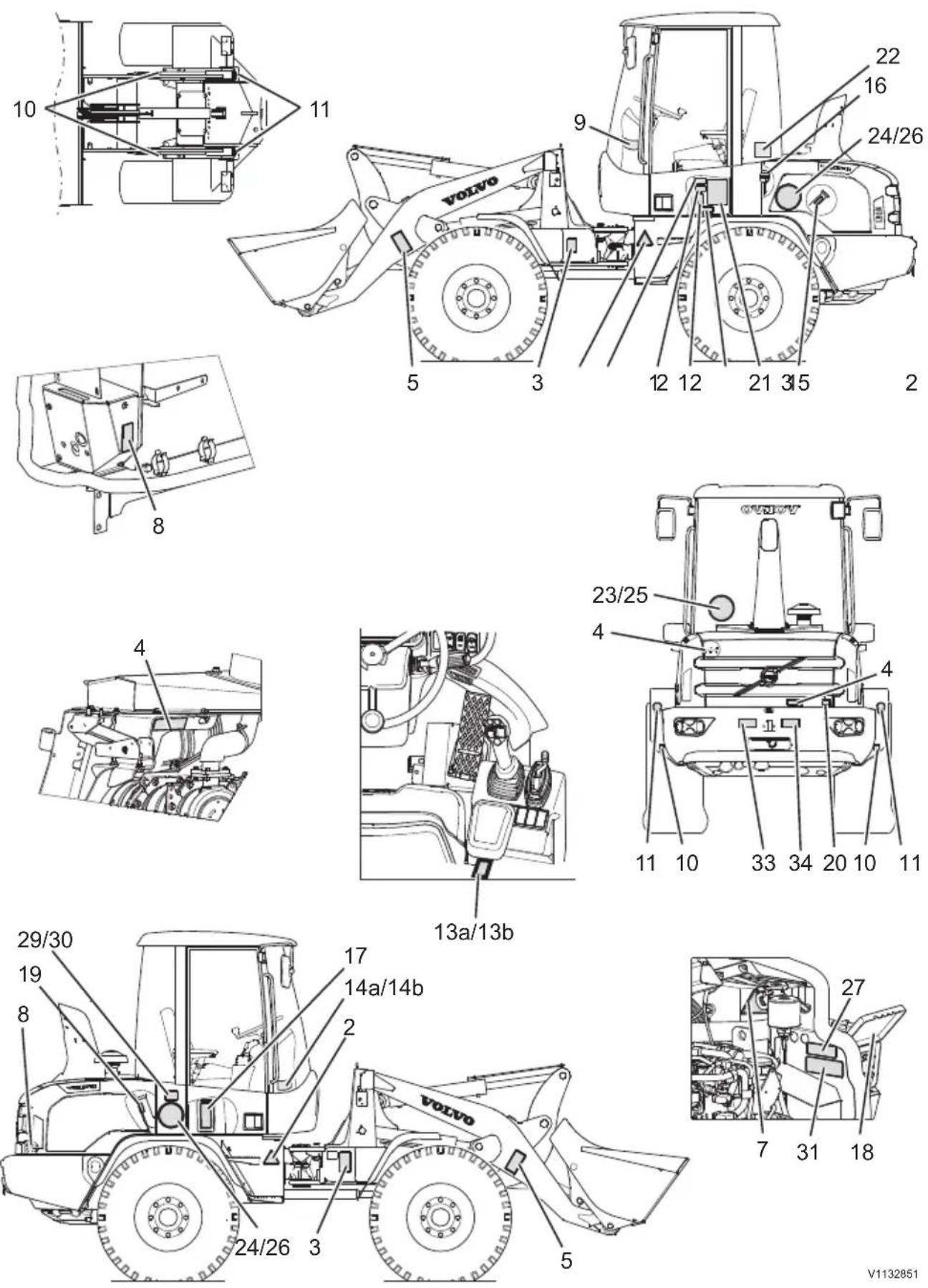
V1132851

1 WARNING! First read the Operator's Manual (Spare parts number for US decal: 13935003)

2 WARNING! Safety alert symbol: Danger area in the immediate vicinity of the machine

3 WARNING! Crushing articulation area. Stay at a safe distance from the machine (Spare parts number for US decal: 15209453)
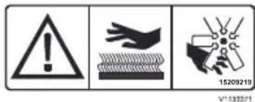
4 WARNING! Hot surfaces and rotating parts. (Spare parts number for US decal: 15209044)

5 WARNING! Do not walk under raised lifting arms. Stay at a safe distance from the machine. (Spare parts number for US decal: 15624249)

6 WARNING! Before welding: Read the Operator's manual

7 WARNING! Hot coolant.

8 WARNING! Before connecting jump leads - read the Operator's Manual. (Spare parts number for US decal: 13935004)

9 WARNING! Check that the attachment is locked (Spare parts number for US decal: 11111506)

10 Attaching point for tie-down

11 Point for lifting
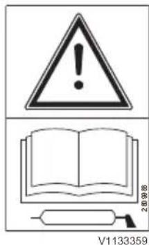
12 Read the Operator's
Manual before carrying out any service and maintenance on the machine

13a Control functions on a single lever with integrated auxiliary hydraulic functions

13b Control functions on a single lever with auxiliary lever
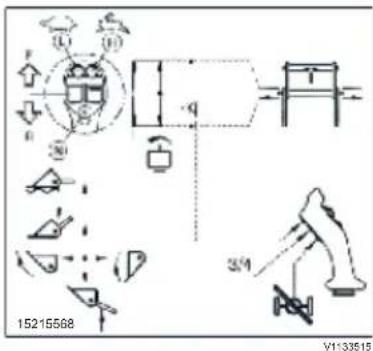
14a Control functions on a single lever with integrated auxiliary hydraulic functions (placed on inside of the front cab window)

14b Control functions on a single lever with auxiliary lever (placed on inside of the front cab window)
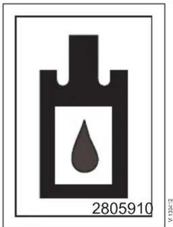
15 Hydraulic oil filling point

16 Brake fluid

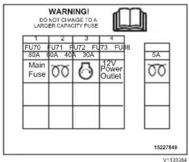
17 Fuses in the cab 18 Fuses in the engine compartment

19 Fuel, filling

20 Battery disconnect switch

21 Lubrication and service chart

22 Sound power level outside the machine

23 20 km/h (placed on inside of the window)

24 20 km/h 25 30 km/h (high speed machines only, placed on inside of the window)

machines only, placed on inside of the window)

26 30 km/h (high speed machines only)
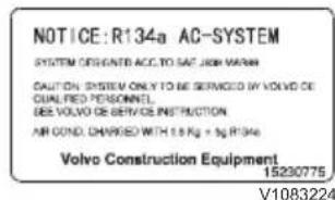
27 Refrigerant R134a (optional with AC)

28 WARNING! Semiautomatic regeneration (Spare part number in USA: 17253504) (positioned inside the cab)

29 Fuel decal (EU only) / Max 10 ppm SULPHUR

30 Fuel decal (US only) / Max 15 ppm SULPHUR

31 Use Volvo coolant VCS only
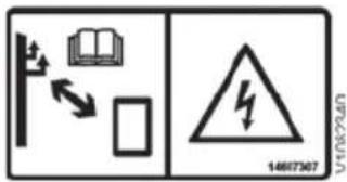
32 Electric power lines, minimal clearance
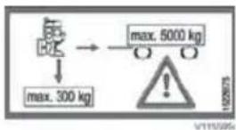
33 Trailer hitch (optional equipment)
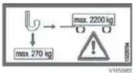
34 Trailer hitch (optional equipment)

35 Driveline shutoff via parking brake (optional equipment) (positioned inside the cab)

natural_image
Two symbolic icons: a person silhouette and a gear, both without any text or symbols.36 Driveline shutoff via seat belt (optional equipment) (positioned inside the cab)
Instrument panels
Keep the manual in the cab so that it is always available for easy reference.

| 1 Instrument panel, front (information display unit, switches, and keypad) |
| 2 Side panel (switches) |
Instrument panel, front

| 1 Keypad 8 Headlights | Headlights, daytime running (optional equipment) | |
| 2 Separate attachment lock 9 Rotating beacon (optional equipment) | ||
| 3 Working hydraulics lock / Control lever lockout | 10 | Back-up alarm (optional equipment) |
| 4 Hazard flashers 11 Electrically heated rear-view mirrors (optional equipment) | ||
| 5 Start key 12 Tiltable rear attachment bracket (optional equipment) | ||
| 6 Regeneration (only with engine model D3.3H) | 13 | Lift fork operation/Hose rupture protection (optional equipment) |
| 7 Wiper and washer, rear window 14 Information display unit | ||
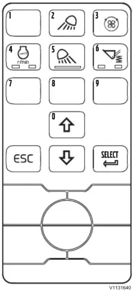
Keypad
1 Keypad
The keypad is used for the display unit and also to directly control the work lights, reversible fan, hand throttle, and the Boom Suspension System. For information about the display unit, see page 43.
NOTE!
The buttons with numbers (0–9) are also used to enter the code for the anti-theft system.
Work lights (#2 (front) and #5 (rear))
Push the buttons to turn the work lights on/off.
With the automatic option installed you have three states of the #5 button.
■ Nothing pressed = off
■ First push = automatic mode
■ Second push = permanent on
Pushing the #5 button again will turn the rear work lights off.
NOTE!
To be able to turn on the work lights, the headlights must be turned on first.
Reversible fan (#3) (optional equipment)
Push the button and keep it pressed in, to reverse the fan's rotational direction.
When the button has been pressed in for approx. 2 seconds, a symbol will be shown on the display unit. Keep the button pressed in long enough to blow out dust or any other materials that may clog the fan.
NOTE!
In some conditions the function has to be used frequently to prevent clogging of the fan.
Hand throttle (#4)
NOTE!
The hand throttle function must not be used when travelling on public roads.
The hand throttle button has a green backlight when the hand throttle function is active.
The hand throttle function can be activated either when moving or for stationary use.
Constant moving use can be activated when:
■ Brake pedal is not applied
■ Engine is running
■ Parking brake is released
■ Operator's seat is occupied
■ Accelerator pedal is pressed to reach desired engine speed
Constant moving use can then be activated by pushing #4 button
Constant moving use is cancelled if:
■ Brake pedal is applied
■ Engine is turned off
■ Parking brake is applied
Operator's seat is not occupied for more than 3 s
■ #4 button is pressed
Constant stationary use can be activated when:
■ Brake pedal is not applied
■ Engine is running
■ Parking brake is applied
■ Gear selector is in neutral position
■ Accelerator pedal is pressed to reach desired engine speed
Constant stationary use can then be activated by pushing #4 button
Constant stationary use is cancelled if:
■ Brake pedal is applied
■ Engine is turned off
■ Parking brake is released
■ Gear selector is not in neutral position
■ #4 button is pressed
Boom Suspension System (#6) (optional equipment)
When the function is activated (the left lamp in the button will light up), the Boom Suspension System engages above a certain speed (3–6 km/h) (1.8–3.7 mph) which can be adjusted on the display unit, see page 43.
If the speed drops below the preset speed, then the BSS-function is disengaged.
This function can only be activated when the engine is running.
1 Lower bucket or other attachment flat on the ground.
2 Press the BSS button to activate the function. The left lamp in the button will light up.
3=Lift up the attachment approx. 0.5 m (20 in) off the ground. The right BSS control light turns on (BSS idle state).
4=When the preset speed has been reached (3–6 km/h) (1.8–3.7 mph), the BSS is activated. The control light in the central instrument turns on with a fixed glow (BSS active state).
5=When the attachment is lowered (almost to the ground) or the travel speed drops below the preset speed, BSS changes back to idle state.
6=BSS is turned off by pressing the BSS button or by turning off the engine.
NOTE!
BSS may not be activated while operating. BSS must be turned off during precision work with the attachment.
2 Separate attachment lock

Separate attachment lock

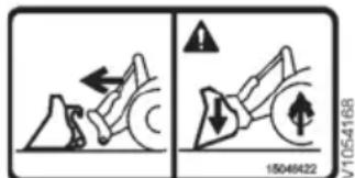
Check that the attachment is locked securely

WARNING
Risk of crushing.
An unsecured attachment could fall and cause serious injury or death.
Always ensure the attachment is properly secured by pressing the front part of the attachment to the ground until the machine is slightly lifted.
The separate attachment lock switch must be pressed in for safety reasons when the attachment is to be disconnected (for example to enable retraction of the lock bolts for the attachment lock).
Rocker switch:
- Switch, upper part pressed in = ready for unlocking.
Disconnect attachment with lever 2 (version 1A) or right roller control (version 1B).
To confirm that the attachment is disconnected, and delete the warning message in the display, press the ESC-key on the keypad.
Attachments can be connected without pressing the rocker switch.
For more information on connecting and disconnecting attachments, see page 136.
natural_image
Simple line drawing of a door with an open lid and oval base, no text or symbols present3 Working hydraulics lock / control lever lockout
For safety, and legal reasons, it is possible to lock the hydraulic functions with this switch – to avoid unexpected movements of boom and attachments if the control levers are affected.
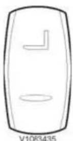
Two-position switch:
■ Switch, upper part pressed in = hydraulic functions unlocked.
■ Switch, lower part pressed in = hydraulic functions locked.
NOTE!
If the machine is equipped with lift forks or hose rupture protection (optional equipment), follow the instructions on page 63.
NOTE!
If the hydraulic system needs to be depressurized, the hydraulic functions must be unlocked (upper part of switch pressed in), see page 140.
NOTE!
When operating on public roads, or if the machine needs to be transported, the hydraulic functions should be locked (lower part of switch pressed in).

Hazard flashers

natural_image
Circular diagram with concentric rings and a central vertical bar, no text or symbols present4 Hazard flashers
Two-position switch.
■ Upper part of switch pressed in = On, all direction indicators on the machine will flash together with the light in the switch and together with the control light for direction indicators. The hazard flashers can be used even if the ignition is in the Off position.
■ Lower part of switch pressed in = Off
5 Ignition
The ignition has 3 positions:
0 Off (key-turn engine stop)
1 Ignition
2 Cranking

V1092165
6 Regeneration (only with engine model D3.3H)
NOTE!
It is important that the engine is warm and not in idle speed (best is above 1400 rpm) for a successful active regeneration!
Semi-automatic regeneration
When the diesel particulate filter is full, a message is shown on the display to indicate that it is time to run a regeneration, see page 109.
Regeneration starts automatically after one minute unless the operator cancels the regeneration.
Regeneration is cancelled by pressing in the lower part of the button.
Two-position switch:
■ Upper part of switch pressed in = regeneration starts.
■ Lower part of switch pressed in = regeneration is cancelled.
Manual regeneration (optional equipment)
NOTE!
If the machine is equipped with manual regeneration, the regeneration must always be started manually by pressing the upper part of the switch.

natural_image
Simple line drawing of a device with a rectangular box and a diagonal line, no text or symbols present.
natural_image
Simple line drawing of a sun icon inside a rounded rectangle (no text or symbols)7 Wiper and washer, rear window
NOTE!
Washing and wiping can take place without the front wiper being on.
Two-position switch:
■ Upper part of switch pressed in = on
■ Lower part of switch pressed in = off
For the washer fluid reservoir, see page 203.
8 Headlights
Three-position switch:
■ Upper part of switch pressed in = headlights are on.
■ Switch in middle position = parking lights and instrument lights are on.
■ Lower part of switch pressed in = lights are off.
NOTE!
To be able to turn on the work lights, the headlights must be on first.

8 Headlights, daytime running (optional equipment)
Three-position switch:
■ Upper part of switch pressed in = headlights are on.
■ Switch in middle position = lights are off.
■ Lower part of switch pressed in = AUTO.
- Ignition on: Parking lights and instrument lights are on.
- Engine running: Daytime running lights are on.
9 Rotating beacon (optional equipment)
Two-position switch:
■ Upper part of switch pressed in = rotating beacon is on.
■ Lower part of switch pressed in = rotating beacon is off.
10 Back-up alarm (optional equipment)
Two-position switch:
■ Upper part of switch pressed in = back-up alarm activated.
■ Lower part of switch pressed in = back-up alarm deactivated.
11 Electrically heated rear-view mirrors (optional equipment)
Two-position switch:
■ Upper part of switch pressed in = electric heating activated.
■ Lower part of switch pressed in = electric heating deactivated.
12 Tiltable rear attachment bracket (optional equipment)
Two-position switch:
■ Upper part of switch pressed in = tilt function activated.
■ Lower part of switch pressed in = tilt function deactivated.

natural_image
Simple line drawing of a door with two side cutouts (no text or symbols)13 Lift fork operation/Hose rupture protection (optional equipment)
Two-position switch:
■ Switch, upper part pressed in = Lift fork operation / Hose rupture protection enabled.
■ Switch, lower part pressed in = Lift fork operation / Hose rupture protection disabled.
Lift fork operation/Hose rupture protection is a safety system, which prevents uncontrolled lowering of the load in case of a hose rupture during lifting.
NOTE!
If the hydraulic system needs to be depressurized, the function needs to be disabled (lower part of switch pressed in), see page 140.
14 Information display unit
Current operating information and vehicle messages are shown on the information display unit. Some settings can also be performed using the keypad.
When the start key is turned to position 1, a test program runs to verify the system, all control lights turn on for two seconds, the pointers in the gauges move to indicate the correct value for fuel level and temperature.
If the machine is equipped with anti-theft device, the information screen will show a request for the code to be entered, see page 43. After the correct code has been entered, the test program will start.

| 1 Central warning (red) |
| 2 Direction indicator, left (green) |
| 3 Direction indicator, right (green) |
| 4 Forward indicator (green) |
| 5 Reverse indicator (green) |
| 6 High speed (green) |
| 7 Parking brake applied (red) |
| 8 Engine oil pressure low (red) |
| 9 Seatbelt unfastened (red) |
| 10 Information screen |
| 11 High beams (blue) |
| 12 Differential lock activated (amber) |
| 13 Regeneration (amber) (only with engine model D3.3H) |
| 14 High exhaust temperature (amber) (only with engine model D3.3H) |
| 15 Coolant temperature |
| 16 Fuel level |

1 Central warning (red)
The light flashes if abnormal operating values or problems arise. Alarm text is shown on the display unit. The buzzer will sound until the required action has been taken.




2 Left direction indicators
The light flashes when the left direction indicators are on.
Irregular flashing indicates a defective bulb, which should be replaced.
3 Right direction indicators
The light flashes when the right direction indicators are on.
Irregular flashing indicates a defective bulb, which should be replaced.
4 Forward travel direction indicator (amber)
The light is on when forward travel direction is selected.
5 Reverse travel direction indicator (amber)
The light is on when reverse travel direction is selected.
6 High speed
The light is on when the machine is in high speed range.
7 Applied parking brake
The light is on when the parking brake is applied.
The buzzer sounds and an alarm text is shown on the display unit if a directional gear is selected.
8 Engine oil pressure low (red)
The light is on when the engine oil pressure is too low.
The buzzer will sound until the required action has been taken.
9 Seatbelt unfastened (red)
The light is on when the seatbelt is not fastened (optional function).
The buzzer sounds if a directional gear is selected (optional function).
10 Information screen
In addition to alarm texts the information screen also shows start sequence, operating information, and settings.

11 High beams
The light is on when the high beams are used.

12 Engaged differential lock
The light turns on when the differential lock is engaged.
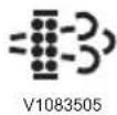
13 Regeneration (only with engine model D3.3H)
The indicator light is on when the diesel particulate filter is full and it is time to run a regeneration, see page 109.

14 High exhaust temperature (only with engine model D3.3H)
The indicator light is on when regeneration of the diesel particulate filter is in progress and indicates that the temperature of exhausts from the outlet pipe is higher than normal.

natural_image
Simple line drawing of a gauge with a bulb, pointer, and thermometer (no text or symbols)15 Coolant temperature
If the gauge indicates in the red sector, the warning light to the right of the gauge turns on.
Run the engine at low idle for a few minutes. If the gauge continues to indicate within the red sector, stop the engine and investigate the cause.
The buzzer sounds if a directional gear is selected and an alarm text is shown on the display unit.

16 Fuel level
When the pointer indicates at empty, the warning light to the left of the gauge turns on and a message is shown on the display unit. The machine should be refuelled as soon as possible to prevent air from entering the system.
Fuel tank, capacity: 84 litres (22 US gal)
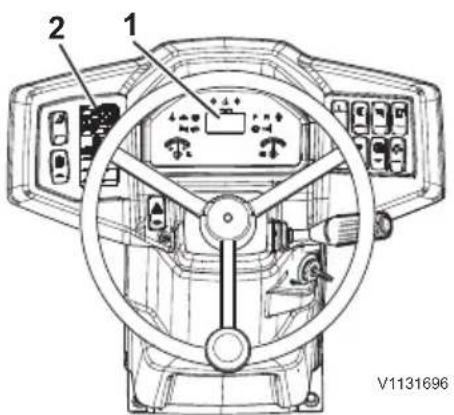
Information display unit 1=Information screen 2=Keypad
Display unit
NOTE!
Prevent machine damage by taking correct action. Read this section thoroughly, understand the instructions, and familiarize yourself with instrument panel before attempting to operate the machine.
The display unit consists of two parts:
- 1 = Information screen (main screen and subscreens)
- 2 = Keypad (escape (ESC), scroll up and down, and SELECT)
Start sequence
When the ignition is turned to start position, the instrument panel's lights and the buzzer will be tested during a few seconds. Make sure that all lights work. After this check, the main screen (which shows engine speed) will appear. If the anti-theft system is active, the anti-theft screen will be displayed to enter the pin code, see below.


Anti-theft system (optional equipment)
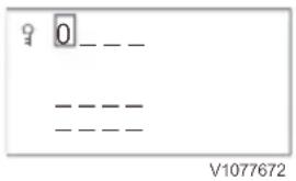
Enter code screen
Enter the code with the buttons (0–9) on the keypad and confirm with SELECT. After the correct code has been entered, the main screen is displayed.
Recovery code screen
If the wrong code is entered more than three times, a recovery code consisting of five digits appears. Note the code and contact your Volvo dealer.
Change secondary code
Press SELECT when the main screen is shown. Press SELECT by the first row with a key symbol. The change code screen is shown.
Enter the old secondary code. Press SELECT. Enter the new code and press SELECT. Repeat the code and press SELECT.

- If the old code is correct and the new code is correctly repeated, a confirmation screen is shown for two seconds.
- If the old code or the new code is incorrect, the change code screen is shown again.
- The old code and the new code may not be the same.
Change primary code
Press SELECT when the main screen is shown. Use the arrow buttons to highlight the second row and press SELECT. The change code screen is shown.
Enter the old primary code. Press SELECT. Enter the new code and press SELECT. Repeat the code and press SELECT.
- If the old code is correct and the new code is correctly repeated, a confirmation screen is shown for two seconds.
- If the old code or the new code is incorrect, the change code screen is shown again.
- The old code and the new code may not be the same.
Main screen
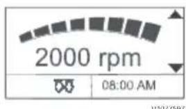
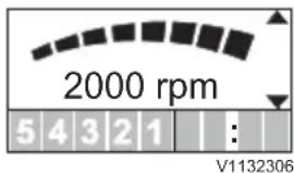
The main screen is divided in three parts:
- The top part shows engine speed.
- The lower left part shows the symbols according to the description in the table below.
- The lower right part shows the current time.
NOTE!
The main screen always shows the engine speed and can always be found by clicking the ESC-button several times.
NOTE!
For the display symbols related to regeneration, see page 109.
| Number | Symbol name | Symbol Active condition | |
| 1 Engine | Preheat |  | Activated when the preheating is active or preheating is requested. |
| 2 Envelope Tray |  V1176105 V1176105 | Activated when the operator needs to be informed of a fault recorded in the Service Mode. | |
| 3 Fan | Reverse On |  V1176102 V1176102 | Activated when fan reverse is on. |
| Number | Symbol name | Symbol | Active | condition |
| 4 Boom | Suspension |  | Activated when the Boom Suspension function is active. | |
| 5 Service | 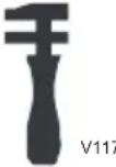 ‘610 ‘610 | Activated when a service is required. |
Check symbols may appear if the system detects something that requires an action, see "check symbols" on the following pages.
Subscreens
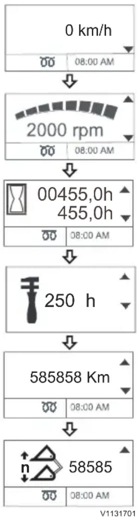
From the main screen (showing the engine speed), different subscreens can be displayed by scrolling up or down (pressing ARROW-UP or ARROW-DOWN on the keypad). When the desired subscreen is shown, press SELECT on the keypad to enter that subscreen's setting mode (setting screen).
Machine speed (optional equipment)
By pressing ARROW-UP from the main screen, the machine speed is displayed in km/h or mph depending on market.
Machine hours and daily hours
By pressing ARROW-DOWN from the main screen, the total machine hours (top value) and the daily machine hours (bottom value) (after the last reset) are shown. By pressing SELECT for a few seconds, the daily machine hours are reset.
Machine hours left before service
By pressing ARROW-DOWN from this screen, the hours left before service appears.
Total machine travel distance (optional equipment) By pressing ARROW-DOWN from this screen, the total machine travel distance is displayed in km or miles depending on market.
Number of bucket cycles (optional equipment)
By pressing ARROW-DOWN from this screen, the number of completed bucket cycles (since the last reset) is displayed.
Set current time
flowchart
graph TD
    A["0 km/h"] --> B["08:00 AM"]
    B --> C["2000 rpm"]
    C --> D["08:00 AM"]
    D --> E["00455,0h 455,0h"]
    E --> F["08:00 AM"]
    F --> G["250 h"]
    G --> H["585858 Km"]
    H --> I["08:00 AM"]
    I --> J["58585"]
    J --> K["08:00 AM"]

By pressing SELECT, the setting screen appears which enables setting of the current time.
Press ARROW-UP or ARROW-UP to adjust and then press SELECT to move to the next position. Press ESC to return to a previous position.
The time can be shown as 12-hour or 24-hour format. Press ARROW-UP or ARROW-DOWN to choose the desired format. Press SELECT to save the setting.
Check symbols on the display unit
Check symbols are surrounded by a square made up of dashed lines.
When this type of message is displayed, the buzzer sounds four times. The message disappears by pressing ESC. The message appears again at the next start of the machine (unless the correct action has been taken by then).

Fuel level low
The symbol is shown when the fuel level is low (approx. 10% of total tank volume). Fill up with fuel to prevent air from entering the fuel system, which can cause unexpected stopping of the machine.
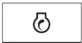
Preheating malfunction
The symbol is shown when preheating malfunctions. Turn off the engine and investigate the cause. If necessary, contact a workshop authorized by Volvo.
Engine coolant temperature high
The symbol is shown when the engine coolant temperature is too high. Turn off the engine and investigate the cause. If necessary, contact a workshop authorized by Volvo. The engine must be cold before accessing the engine compartment. Turn the ignition to position II. The engine coolant's temperature gauge must
show minimum temperature. Check the coolant level and make sure that the radiator is clean.

V1177117

30 h
V1093159

V1093160

V1093194

V1093156

V1093166
Engine failure
The symbol is shown for generic engine errors. Contact a workshop authorized by Volvo.
Time to service
The symbol and hours show the time remaining before service has to be performed. Press ESC to confirm. The symbol will show up in the lower left corner of the main screen.
Attachment bracket verification (optional equipment)
The symbol is shown when the attachment is locked to the attachment bracket (i.e., when the switch for separate attachment lock has been released). Check that the attachment really is connected correctly and press ESC to confirm.
Hydraulic oil filter clogged
The symbol is shown when the hydraulic oil filter is clogged.
NOTE!
If the symbol remains after the machine has reached normal operating temperature, the filter may have to be replaced. Contact a workshop authorized by Volvo.
Engine air cleaner clogged
The symbol is shown when the engine's air cleaner is clogged. Reduce engine speed to minimum. Clean the primary filter in the engine's air cleaner, see page 191. Contact a workshop authorized by Volvo if the filter has to be replaced.
Hydraulic oil temperature low
The symbol is shown when the hydraulic oil temperature is low. Warm up the engine before the machine will be used for normal operations.

V1177538

Automatic XX s
V1132305
Hydraulic oil temperature high
The symbol is shown when the hydraulic oil temperature is too high. Check that the fan works correctly. Turn off the engine, verify oil level, and investigate the cause. If necessary, contact a workshop authorized by Volvo.
NOTE!
Check that no levers are still in "hold position" – this heats the hydraulic oil quickly.
Auto engine shutdown (optional equipment)
The symbol shows seconds remaining to automatic shutdown of the engine, from 60 seconds counting down to 0.
Warning symbols on the display unit
Warning symbols are surrounded by a square with a solid border.
When this type of message is displayed, the central warning light turns on, the buzzer sounds, and the relevant light symbol in the display unit is activated (if the light symbol exists for the current warning message). Press ESC once to turn off the buzzer (the light symbol will still be activated). Press ESC again to turn off the light symbol. The central warning light will remain activated until the warning condition has ceased (i.e., the primary cause for the warning message has been resolved).

V1093195
Hydraulic oil temperature high
The symbol is shown when the hydraulic oil temperature is too high. Check that the fan works correctly. Turn off the engine, verify oil level, and investigate the cause. If necessary, contact a workshop authorized by Volvo.
NOTE!
Check that no levers are still in "hold position" – this heats the hydraulic oil quickly.

V1077659
Battery charge error
The symbol is shown when the battery is not being charged or the system voltage is too low.
Investigate the cause. If necessary, contact a workshop authorized by Volvo.
V1177120
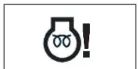
Preheating failure
The symbol is shown when preheating fails.
Turn off the engine and investigate the cause.
If necessary, contact a workshop authorized by Volvo.

V1096363
Engine coolant temperature high
The symbol is shown when the engine coolant temperature is too high. Turn off the engine and investigate the cause. If necessary, contact a workshop authorized by Volvo.
The engine must be cold before accessing the engine compartment. Turn the ignition to position II. The engine coolant's temperature gauge must show minimum temperature. Check the coolant level and make sure that the radiator is clean.

V1177205
Water-in-fuel
The symbol is shown when there is water in the fuel. Drain the water trap if needed, see page 189.

V1077655
Computer failure
The symbol is shown when there is a communication error between the control units. Contact a workshop authorized by Volvo.
V 10931
Engine / machine speed too high
The symbol is shown when the engine and/or machine speed is too high. Back off on the throttle to decrease engine speed and use brakes if necessary.

V10931 98
Attachment bracket (ready to connect/disconnect attachment) (optional equipment)
The symbol is shown when the attachment bracket is ready to connect or disconnect attachments (i.e., for as long as the bottom part of the switch for separate attachment lock is pressed in, the attachment bracket's lock pins can be moved in or out of the attachment).
natural_image
Simple line drawing of a water droplet inside a container with directional arrows (no text or symbols)
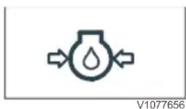
Engine oil pressure low
The symbol is shown when the engine oil pressure is too low. Turn off the engine and investigate the cause. If necessary, contact a workshop authorized by Volvo.
Engine failure
The symbol is shown for generic engine errors. Contact a workshop authorized by Volvo.
Instrument panel, side
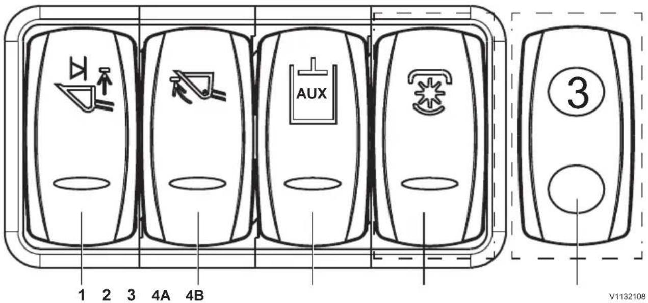
| 1=Automatic lift (boom kick-out) (optional equipment) |
| 2=Automatic tilt (bucket positioner) (optional equipment) |
| 3=High flow auxiliary hydraulics (optional equipment) |
| 4A=Water pump for road sweeper (optional equipment) |
| 4B=Indicator for auxiliary hydraulics (optional equipment) |

1. Automatic lift (boom kick-out) (optional equipment)
This function, along with the function automatic tilt (bucket positioner), causes the attachment to automatically stop in predetermined positions. This will result in shorter cycle times and reduced wear. The sensor position can be moved to adjust the lift height for when the boom will stop during automatic lift, see 65.
NOTE!
Automatic operation can be stopped by moving the control lever into the neutral position or by deactivating the switch for the respective function.
Three-position switch:
■ Switch, upper part pressed in = Hold (detent function) activated
■ Switch in middle position = boom kick-out activated.
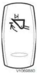
■ Switch, lower part pressed in = Hold (detent) function for lift position deactivated / boom kick-out deactivated.
NOTE!
The boom kick-out lift height can be adjusted by moving the retainer for the sensor, see page 65.
2. Automatic tilt (bucket positioner) (optional equipment)
NOTE!
Function is standard for machines with TP-linkage.
Two-position switch:
■ Switch, upper part pressed in = Adjusting tilt position / bucket positioner activated.
■ Switch, lower part pressed in = Hold (detent) function for tilt position / bucket positioner deactivated.
NOTE!
The automatic tilt position can be adjusted by moving the retainer for the sensor, see 64.
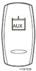
3. High flow auxiliary hydraulics (optional equipment)
This function is normally used when working with attachment that requires a high hydraulic flow, such as a milling equipment.
Two-position switch:
■ Switch, upper part pressed in = High flow auxiliary hydraulics activated.
■ Switch, lower part pressed in = High flow auxiliary hydraulics deactivated.
4A. Water pump for road sweeper (optional equipment)
This function is normally used for road sweeping in dusty conditions.
Two-position switch:
■ Switch, upper part pressed in = water pump activated.
■ Switch, lower part pressed in = water pump deactivated.
natural_image
Simple line drawing of a rectangular object with a central emblem and an oval base (no text or symbols)
V1177915
4B. Indicator for auxiliary hydraulics (optional equipment)
Indicator:
■ Indicator lamp is lit when 3rd hydraulic function is activated
■ Indicator lamp is not lit if 4th hydraulic function is activated. Selection is valid until switched back to 3rd hydraulic function, or if the engine is turned off.
Other controls
Controls

| 1=1A: Single lever with Aux lever (standard)1B: Single lever with integrated Aux hydraulic functions (optional equipment) | 7=12V socket |
| 2=Multi-function lever (light switch / direction indicators / horn / windshield wiper/washer system) | 8=Heating and ventilation with mechanical control |
| 3=Steering wheel, adjustment=9=Armrest, adjustment | |
| 4=Drive pedal / Accelerator pedal=10=Lever carrier, adjustment | |
| 5=Inching-brake pedal=11=Hand-inching control (optional equipment) | |
| 6=Parking brake lever | Available for single and dual lever |
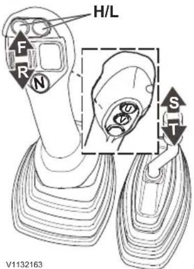
1A Single lever with Aux lever
Travel direction selection
Forward: Push the upper part of the button for Forward (F) travel direction.
Reverse: Push the lower part of the button for Reverse (R) travel direction.
NOTE!
Reduce machine speed as much as possible when changing travel direction.
NOTE!
The selected travel direction (F = Forward or R = Reverse) is shown on the display in the information panel when the parking brake is not applied, the parking brake lever is fully released, and the relevant control light is off.
Neutral: Press button (N) to go to neutral position.
Gear selection
Push either of the two upper buttons (H/L) to change between high and low range.
NOTE!
Choose low range if going down a steep downhill to control machine speed.
NOTE!
The rabbit symbol is shown on the display when high range is selected.
NOTE!
Always make sure that the parking brake is fully released and that the relevant control light is off. The red central warning is shown and the buzzer sounds if a travel direction is selected with the parking brake applied.
Controls for attachment lock and auxiliary hydraulics (Aux lever)
Neutral position: Not activated (spring-centred) S = Unlock attachment, and for using auxiliary hydraulics
T = Lock attachment, and for using auxiliary hydraulics (with hold function)
NOTE!
Make sure that the lever is not in the hold position for a long time since this increases the hydraulic oil temperature quickly.
1B Single lever with integrated Aux hydraulic functions (optional equipment)
Travel direction selection
Forward: Push the upper part of the button for Forward (F) travel direction.
Reverse: Push the lower part of the button for Reverse (R) travel direction.
NOTE!
The selected travel direction (F = Forward or R = Reverse) is shown on the display in the information panel when the parking brake is not applied, the parking brake lever is fully released, and the relevant control light is off.
Neutral: Press button (N) to go to neutral position.
Gear selection

Push either of the two upper buttons (H/L) to change between high and low range.
NOTE!
Choose low range if going down a steep downhill to control machine speed.
NOTE!
The rabbit symbol is shown on the display when high range is selected.
NOTE!
Always make sure that the seat belt is fastened and parking brake is fully released and that the relevant control light is off. The red central warning is shown and the buzzer sounds if a travel direction is selected with the parking brake applied. For further information about the function Drive line shutoff. See page, 78
Controls for attachment lock and Aux hydraulics (right control knob)
Neutral position: Not activated (control knob is spring-centred)
S = Unlock attachment, and activate/using the auxiliary hydraulic function in defined direction.
T = Lock attachment, and activate/using the auxiliary hydraulic function in defined direction
NOTE!
For using auxiliary hydraulics, the control knob provides proportional control. The more the knob is moved out of neutral position, the higher the attachment speed resp. the oil flow will be.
Hold function: Button (U) pressed in.
■ Activation:
1=Operate the roller control to the desired position and hold it there.
2=Press the hold button and keep it there.
3=Release the roller control.
4=Release the hold button. The red LED control light (Y) in the handle turns on.
■ Deactivation: Press the hold button when roller control is not operated at all. As an alternative, simply move the roller control in any direction S

or T momentarily. The red LED control light (Y) in the handle turns off.
NOTE!
The hold function must not be used for locking or unlocking the attachment.
NOTE!
When hold function has been activated, the roller control returns to middle position.
■ 4th hydraulic function: Button (V) pressed in. The 4th hydraulic function can be used for as long as the button is pressed in.
Flow adjustment knob for attachment lock and Aux hydraulics (K)
Use the oil flow adjustment knob (K) to adjust to a desired operating speed of the attachment functions controlled by the right control knob.
For example, when working with a grapple bucket, the max. oil flow is easy to adjust. The full stroke of the roller control (S - T) is used for sensitive control of the attachment.
NOTE!
For safety reasons, the adjustment must only be performed when the attachment lock or Aux hydraulics are operated.
1 Turn the knob all the way to the right (clockwise) to Min.
2 Operate roller control fully in direction S or T and, at the same time, increase oil flow by turning the knob counter-clockwise.
■ Reduce oil flow down to zero: Turn the knob clockwise.
■ Increase oil flow up to max.: Turn the knob counter-clockwise.

natural_image
Technical line drawing of a mechanical lever assembly (no text or symbols)W Differential lock button

Differential lock light
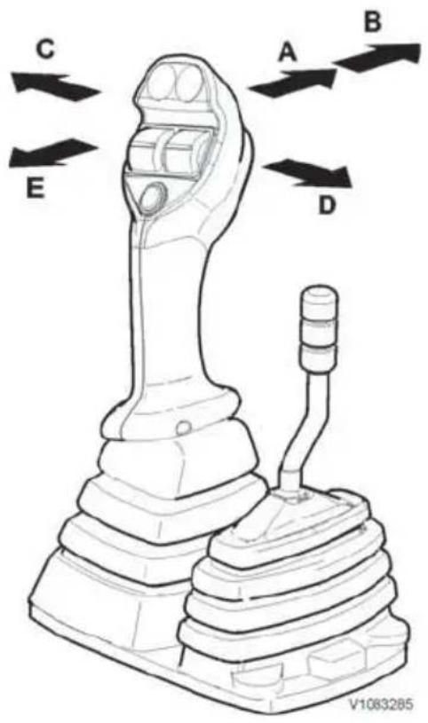
Loader functions
Neutral position: Not activated (spring-centred)
A=Lowering
B=Float position (with hold function)
C=Tilt back (with hold function, see page51.)
D=Tilt forward
E=Lift (with hold function, see page51.)
Differential lock function
- Button W pressed in = differential lock engaged on the front axle and rear axle.
The differential lock light turns on when the differential lock is engaged.
NOTICE
If the machine has become stuck and one of the wheels is spinning, the wheel must be stopped before engaging the differential lock. Otherwise the drive axle system may be damaged.
NOTE!
When releasing the button, the differential locks may not disengage immediately (due to the friction on the contact areas caused by the differential torques). Then deactivate drive and perform steering movements so that the differential torque is reduced and the differential locks on the front axle and rear axle disengage.
NOTE!
The differential lock shall only be used when operating on slippery ground. When operating on firm ground, especially when turning, the differential lock must be disengaged.
natural_image
Technical line drawing of a cylindrical device with ports and a threaded end (no text or symbols)
natural_image
Interior view of a vehicle dashboard with labeled components (no readable text or symbols)A Lock lever
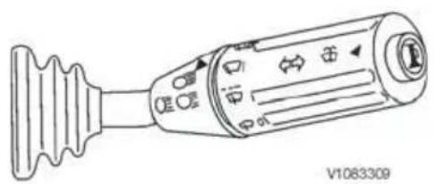
2 Multi-function lever
Direction indicator, horn
- Lever forward = Left direction indicator
- Lever backward = Right direction indicator
- Button pressed = Horn
Headlights
- Lift the lever towards the steering wheel = High/low beams
Windshield washer system
- Push the ring toward the steering wheel = Windshield washer system
Windshield wiper (turning of lever)
- Position 0 = Neutral position
- Position 📋 = Interval wiper
- Position I = Windshield wiper, normal speed
- Position II = Windshield wiper, high speed
3 Steering wheel, adjusting
Adjusting the steering wheel angle
NOTE!
Only make adjustments when the machine is parked, never when driving or operating.
- Press down lock lever (A) to adjust the steering wheel angle.
- Release the lock lever to lock at the desired angle.
NOTE!
After adjusting, check that all levers have sufficient clearance when operated.
4 Drive pedal / Accelerator pedal
The drive pedal is used to control travel speed via the engine speed.
NOTE!
When the drive pedal is let up completely when operating, the machine will decelerate to a standstill.
5 Inching-brake pedal
The inching-brake pedal enables matching of the wheel loader's travel speed to the current travel situation, regardless of the drive pedal's position.
Actuating the inching-brake pedal while the drive pedal is pressed down all the way (highest possible

lift speed of the bucket) reduces the travel speed to a minimum (approaching a truck).
Wearless hydrostatic braking
The inching-brake pedal provides hydrostatic braking via the transmission during the first part of its stroke, without wearing the service brakes.
When the brake pedal is pressed down more, the service brakes will be applied.
6 Parking brake lever
The control light is activated when the parking brake lever is used and has left its bottom position.
NOTE!
Always make sure that the seat belt is fastened and parking brake is fully released before selecting gear. For further information about the function Drive line shutoff. See page, 78
7 12 V socket

natural_image
Interior view of a vehicle dashboard and infotainment unit (no visible text or symbols)12 V socket

natural_image
Interior view of a vehicle showing dashboard, steering wheel, and battery pack (no text or symbols)A Heating and ventilation with mechanical control
8 Heating and ventilation with mechanical control
For more information, see page 71.

natural_image
Interior view of a vehicle showing dashboard, steering wheel, battery pack, and labeled component A (no text or symbols beyond labels)A Adjustment knob for armrest
9 Armrest, adjustment
Turn the adjustment knob counter-clockwise to adjust the height of the armrest. Turn clockwise to lock at desired height.

natural_image
Interior view of a vehicle showing dashboard, steering wheel, and battery compartment (no text or symbols)A Adjustment knob for lever carrier
10 Lever carrier, adjustment
Turn the adjustment knob to adjust the angle of the lever carrier.

natural_image
Technical line drawing of a vehicle's interior dashboard and steering wheel (no text or symbols)11 Hand control for inching (optional equipment)
The hand-inching control (a rotary knob) enables matching of the machine's travel speed to the application, independent of the drive pedal's position.
The rotary knob is located behind the control lever for lift arms and bucket.
- Turn the hand-inching control counter-clockwise to stop (open = no drive).
- Adjust engine speed with the drive pedal or the hand throttle control to the required speed.
- Select directional gear (Forward / Reverse).
- Turn the hand-inching control clockwise (close) until the desired travel speed is reached.
NOTE!
During normal machine operation, the hand-inching control must be completely closed (turned clockwise to stop)!
Lifting fork operation / Hose rupture (optional equipment)

WARNING
Risk of crushing.
An unsecured attachment could fall and cause serious injury or death.
Always ensure the attachment is properly secured by pressing the front part of the attachment to the ground until the machine is slightly lifted.
Lift fork operation/Hose rupture protection is a safety system, which prevents uncontrolled lowering of the load in case of a hose rupture during lifting work (loading fork - loading hook operation).
- Switch, upper part pressed in = Lift fork operation / Hose rupture protection enabled.
- Switch, lower part pressed in = Lift fork operation / Hose rupture protection disabled.
natural_image
Simple line drawing of a door with two side opening holes (no text or symbols)
A Edge saver, underside flat against ground
B Nut (for adjusting tilt position indicators)
C=Tilt position indicators
D=Indicator pin
NOTICE
"Lowering or Tilting forward" is not possible after the engine has been shut down and ignition key is in running position (1).
- The switch "Work hydraulics / Control lever lockout" must be in position "Unlocked" = Lower part of switch pressed in.
Before starting maintenance or repair work, make sure that the engine is turned off and the ignition key is in position 1. The control levers and knobs for the work hydraulics must be operated several times to all end-positions. Work on hydraulic systems must only be performed by authorized personnel.
Automatic tilt (bucket positioner)
Automatic tilt ensures that the attachment stops automatically in the set position when the attachment is tilted back (in) with the lever in locked position. This will result in shorter cycle times and reduces wear.
NOTE!
Automatic tilt can be used and set for various attachments. A bucket is used in the instructions below and the automatic tilt (bucket positioner) is set to deploy when the underside of the bucket's edge saver is parallel with the ground surface. This common setting means that the edge saver absorbs most of the wear, which minimizes wear on the rest of the bucket.
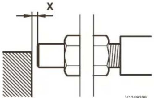
The distance (X) between the indicator pin and the sensor should be 3–5 mm.
NOTE!
The tilt position indicators can be adjusted for one attachment and the sensor for another. If the tilt position indicators are adjusted, the sensor must always be adjusted afterwards since the sensor has been moved when the tilt position indicators were adjusted!
Adjusting
1 Position the bucket so that the underside of the edge saver is flat against the ground (see figure).
2 Turn off the engine, but leave the start key in running position.
3 Check that the distance between the sensor and the indicator pin is 3–5 mm. Otherwise, adjust by loosening one of the nuts and moving the sensor to correct distance with the other nut. Then tighten both nuts.
4 If the tilt position indicators need to be adjusted, loosen the nut and move to the desired position. Then tighten the nut.
5 Loosen the nut for adjusting the sensor and move the sensor to the exact position when the light-emitting diode on the back of the sensor is not lit (exactly when the sensor is in line with the end of the indicator pin). Then tighten the nut.
6 Activate automatic tilt (bucket positioner) with the switch.
7 Start the engine and lift the bucket so that the bucket can be tilted forward (out). Check the adjustment by first tilting the bucket forward a bit and then tilting back the bucket with the lever in locked position. Then the bucket should tilt back automatically and remain in the position that was set.
8 Lower the bucket against the ground (without tilting the bucket) and check that the edge saver's underside rests flat on the ground once again.

Automatic tilt (bucket positioner)
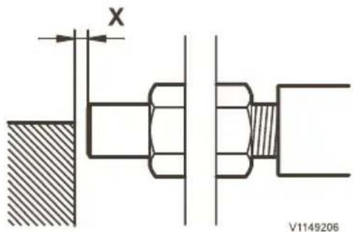
The distance (X) between the lift arm and the sensor should be 3–5 mm.

A Nut
B Lift arm (boom)
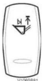
Automatic lift (boom kick-out)
Automatic lift (boom kick-out)
Automatic lift (boom kick-out) ensures that the attachment stops automatically in the set position when the attachment is raised with the lever in locked position. This results in shorter cycle times and makes work easier.
Adjusting
1 Lift the attachment to the desired position.
2 Turn off the engine, but leave the start key in running position.
3 Check that the distance between the sensor and the lift arm (boom) is 3–5 mm. Otherwise, adjust by loosening one of the nuts and moving the sensor to correct distance with the other nut. Then tighten both nuts.
4 Loosen the nut for adjusting the sensor and move the sensor to the exact position when the light-emitting diode on the back of the sensor is not lit (exactly when the sensor is in line with the edge of the boom). Then tighten the nut.
5 Activate automatic lift (boom kick-out) with the switch.
6 Start the engine and lower the attachment slightly. Check the adjustment by raising the attachment with the lever in the rear lock position. Then the attachment should stop automatically in the set position.
Operator comfort
Operator seat
The operator's seat meets the criteria according to EN ISO 7096. Briefly, this means that the seat is designed to minimize whole-body vibrations during machine operation. The amount of vibration depends on different factors, many of which are not related to the construction of the machine, such as ground conditions, speed and operating techniques. Note the following:
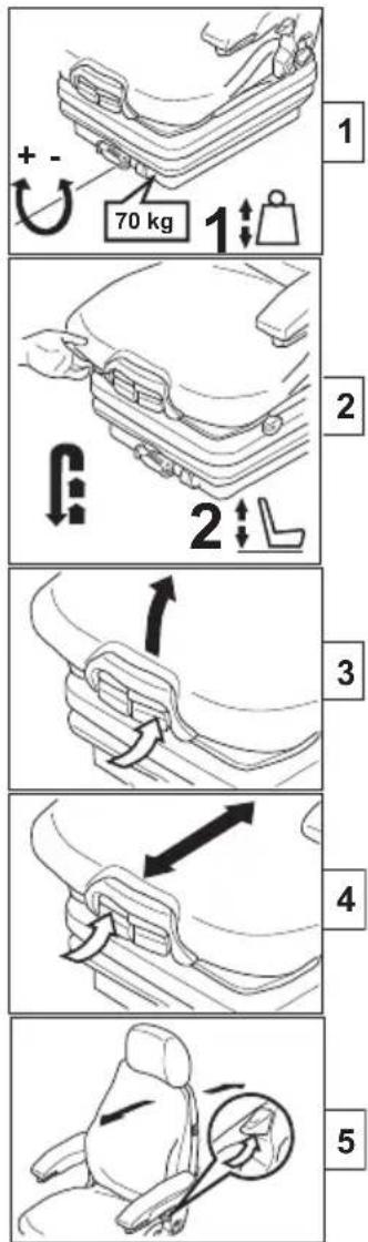
V1132211
- Adjust the seat according to the operator's weight and height.
- Keep the ground on the work site in good condition.
- Choose the correct operating technique and speed for the current conditions.
NOTICE
Do not adjust the operator seat while the machine is moving.
A correctly adjusted operator's seat enhances operator comfort and safety. An incorrectly adjusted seat may lead to injuries. The adjustments that can be made are:
1 Weight adjustment: Turn the lever until your weight is shown on the indicator.
NOTE!
Do not sit in the seat while adjusting.
2 H Height adjoint: Lift the operator's seat to the desired height until it audibly snaps into place. When the seat has been raised above the highest setting (end-stop) it drops back down to its lowest position.
3 Seat cushion angle adjustment: Pull up on the left handle and push down or pull up the front part of the seat cushion to adjust to desired angle.
4 Seat depth adjustment: Pull upon the right handle and move the seat cushion forward or backward to desired position.
NOTE!
After fore-aft adjustment, the lock handle must lock into place with an audible click. Then it should not be possible to move the operator's seat.

5 Backrest adjustment: Pull up the lock catch and move the backrest to the desired position. Then release the lock catch.
NOTE!
The backrest is spring-loaded to forward direction when the lock catch is pulled upward.
NOTE!
It should not be possible to move the backrest when the lock catch has been released.
Air suspended seat (optional equipment)
The adjustments are carried out in the same way as for the mechanical seat (see page 67), except for the weight and height adjustment.
1 Weight and height adjustment: Pull up or push down on the lever (1) until the indicator (2) only shows green.
NOTE!
Vibrations are absorbed in an optimal way in the green area.
NOTICE
Do not operate the function more than 60 seconds to avoid damage.
6 Lumbar support (optional equipment): Use the two switches (on the back of the seat) to adjust for lumbar support. The upper switch for the upper part of the backrest, and the lower for the lower part of the backrest.
NOTE!
Do not press hard against the backrest during adjustment in order to maintain easy operation.
7 Seat heater (optional equipment):
- 0 = seat heater OFF
- 1 = seat heater ON
8 Fore/aft isolator (optional equipment): This function should be activated during certain operating conditions so that the operator's seat better absorbs shocks and impacts in the travel direction.
- 1 = activated
- 2 = deactivated
NOTE!
After choosing position 1, push back the operator's seat all the way until the lock handle locks with an audible click.
NOTE!
It should not be possible to move the seat when the lock handle has locked.
Seat belt

WARNING
Risk of serious injury!
Unexpected machine movement can cause the operator to be ejected from the machine, causing serious injuries.
Operate the machine only while seated in the operator seat with the seat belt fastened.
The seatbelt is critical to operator safety. It must always be worn and fastened when the machine is used to prevent the operator from being ejected out of the cab or off the operator platform if the machine rolls over, tips over, or is involved in an accident. A fastened seatbelt also helps the operator to maintain control of the machine if it moves suddenly or in an unexpected way. Failure to use the seatbelt when the machine is used can lead to serious injuries or fatal accidents. The seatbelt is only intended for one adult. Make sure that the seatbelt is reeled-in when not in use.

WARNING
Risk of serious injury or death.
A damaged seat belt could cause serious injury or death.
Check the seat belt and associated parts before start of machine operation.
Check the seatbelt and associated parts every day. Make sure that fasteners and installation parts are well-tightened. Replace the whole seatbelt immediately if there is any wear, the belt is worn, frayed, has loose stitching, if the belt is deformed, or if the seatbelt's reel does not work. Replace the seatbelt if the machine has been involved in an
accident where the belt has been stretched, strained, or subjected to high forces. Check fasteners and installation parts. It is forbidden to change or modify the belt or its attachments and fasteners. Only use warm water when cleaning, do not use cleaning agents or detergents. Let the belt dry while it is pulled out, before reeling it in. Volvo Construction Equipment recommends replacement of seatbelt units every 3rd year regardless of appearance.
Climate control system
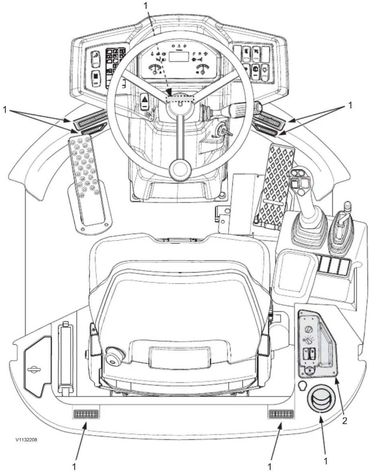
1 Ventilation nozzles
2 Heating and ventilation with mechanical control
1 Ventilation nozzles
Use the ventilation nozzles to distribute the air in a suitable way.

A Fan control (in 3 steps)
B Control for fresh air / cab air circulation
C Temperature control
D Air conditioning (optional equipment)
2 Heating and ventilation with mechanical control
A Fan control in three steps
B Control for fresh air / cab air circulation
C Temperature control
D Air conditioning (optional equipment)
The best warming effect in the cab is achieved with maximum temperature (red zone), maximum fan speed, and with cab air circulation selected.
If minimum temperature (blue zone) and "fresh air" position are selected, fresh air will flow into the cab through the cab ventilation filter.
NOTE!
In case of poor flow or if the windows mist up, the cab ventilation filter may be clogged and needs to be cleaned. See page 202.
Select cab air circulation when the air conditioning system is turned on for cooling. This prevents the system from sucking warm air from outside and results in faster cooling. Switch to fresh air when a comfortable climate inside the cabin is reached.
Continues cab air circulation should only be used in case of bad smells or for quick heating of the cab.
There is a risk that the windows may fog up.
The best air conditioning effect is achieved when the windows and doors are kept closed.
NOTE!
The air conditioning system is not activated if the fan control is off.
NOTE!
Turn on the air conditioning system one or two times a month (also in winter) so that the compressor rotates several times for self-lubrication. Drying out can cause leaks.
Heater Engine-independent
(optional equipment)
NOTE!
The heater unit is not permitted for operation using bio-Diesel.
For additional information regarding safety instructions, instrumentation and maintenance, refer to operating instructions for the relevant engine.


Controls
1 Time
2 Pre-selection
3 Heating ON / OFF
4 Back
5 Advance
6 Memory display
7 Weekday or pre-selected day
8 Current time or pre-selected time
9 Temperature display
10 Operating indicator
Temperature pre-selection - control range 10 to 30 °C (50 - 86 °F)
Heating operation without pre-selection with ignition "OFF"
Switching on the heating
- push button (3), control light comes on.
- turn the rotary control (11) to pre-select the desired temperature.
The operation indicator (10) and the heating duration indicator will be shown in the display.
NOTE!
The heating duration is preset to 120 minutes at the works. It can however be changed one-off or permanently as desired.
Switching off the heating
- push button (3), control light goes out.
NOTE!
For cooling purposes, the fan on the heating unit will run on for approx. 4 minutes after switching off.
Heating operation without pre-selection with ignition "ON"
Switching on the heating
- push button (3), control light comes on.
- turn the rotary control (11) to pre-select the desired temperature.
The operation indicator (10) and time and weekday will be shown in the display.
The heater will remain in operation as long as the ignition is switched on.
If the ignition is switched off, there will still be 15 minutes of time remaining. This can be extended up to a maximum of 120 minutes by pressing button (5)
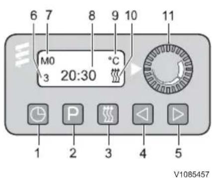
or reduced to a minimum of 1 minute by pressing button (4).
Switching off the heating
- push button (3), control light goes out.
NOTE!
For cooling purposes, the fan on the heating unit will run on for approx. 4 minutes after switching off.
Regulation during heater operation
During operation of the heater the space temperature / the temperature of the heated air drawn in is constantly measured. If the temperature is higher than that pre-selected on the controller, the regulator will cut in, meaning that the heat flow delivered by the heater needs adjusting to the level required. The fan speed will then depend on the regulator setting. If even at the lowest regulator setting the set temperature is still exceeded, then the heater unit will revert to regulator setting "OFF" with the fan running on for approx. 4 minutes to provide cooling. After that the fan will run at minimum speed until restarting.
Setting the duration of heating
Changing the heating duration one-off
■ switch on the heating.
■ to shorten heating duration (to a minimum of 1 minute) push button (4).
■ to extend heating duration (to a maximum of 120 minutes) push button (5).
Changing the heating duration permanently
■ heating switched off.
■ push button (4) and hold pressed (approx. 3 seconds) until the indication appears and flashes. Briefly release the button, then use button (4) or (5) to set the heating duration (from 1 to 120 minutes).
■ when the indicator goes out then the new heating duration is saved in the memory.
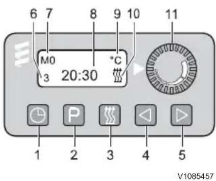
Setting the time and weekday
Setting the time and weekday for the first time
■ briefly push button (1), the time indication will flash 12:00
■ use button (4) or (5) to set the current time. As soon as the entry no longer flashes, it is saved in the memory.
■ then the weekday will flash. Use button (4) or (5) to set the current weekday. As soon as the entry no longer flashes, it is saved in the memory.
NOTE!
With the ignition switched on, the time and weekday are permanently displayed. With the ignition switched off the display disappears after approx. 10 seconds.
Adjusting the time and weekday
■ hold button (1) pressed until the time flashes.
■ use button (4) or (5) to set the current time. As soon as the entry no longer flashes, it is saved in the memory.
■ then the weekday will flash. Use button (4) or (5) to set the current weekday. As soon as the entry no longer flashes, it is saved in the memory.
Pre-selecting start of heating
Three start-times can be pre-selected within 24 hours or up to 7 days in advance.
NOTE!
Only one start-time can be activated at any one time.
Selecting and activating the memory
■ select the first memory - press button (2) once memory display: 1 (basis setting 12 00)
■ select second memory - press button (2) twice memory display: 2 (basis setting 12 00)
■ select third memory - press button (2) three times memory display: 3 (basis setting 12 00)
Setting pre-select time - heating start within 24 hours
■ the pre-selected day appears automatically - no setting necessary.
■ press button (2) repeatedly until the desired memory display (1, 2, 3) appears and flashes
■ briefly press and then release button (4) or (5). The preselected time is displayed and flashes.

V1085457
■ use button (4) or (5) to set the pre-selected time for heating start.
NOTE!
Setting is only possible while the pre-selection is flashing. To reselect: press button (2) again.
Heating start later than 24 hours max. 7 days in advance Setting pre-select time
■ press button (2) repeatedly until the desired memory display (1, 2, 3) appears and flashes.
■ briefly press and release button (4) or (5). The pre-selected time is displayed and flashes.
■ use button (4) or (5) to set the pre-selected time for heating start.
■ approx. 5 seconds after setting the pre-select time the preselect day will flash.
■ use button (4) or (5) to set the pre-select day for heating start.
NOTE!
The pre-select time and day are saved as soon as the time display goes out or switches over to displaying the current time. The memory display shows the activated memory and additionally button (3) will flash.
Neutral setting - no memory activated
■ press button (2) repeatedly until the memory display goes out.
Checking the activated memory
■ the pre-select time for the memory displayed is shown for approx. 5 seconds. Then it will go out or the time will be displayed (with ignition switched on).
■ the display of the pre-select time and pre-select day can then be called up by pressing button (2) for approx. 5 seconds.
After power failure the display will show all signals flashing. Complete resetting is then necessary.
Operating instructions
This section contains rules that must be followed for safe work with the machine. However, these rules are to be followed in conjunction with laws and other national regulations applicable to road safety and labour welfare.
Alertness, judgement and respect for applicable safety regulations are conditions for avoiding risk of accidents.
Running-in instructions
During the first 100 hours, the machine should be operated with particularly great care. During the running-in period it is important to check oil and fluid levels often.
Wheel bolts should be check-tightened after 8 hours operation, see page 201.

Warning message for “engine speed too high”
Engine protection - Software
If the engine speed is too high, there are two functions to protect the engine from damages.

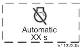
Auto engine shutdown symbol
Engine overspeed monitoring
This function informs the operator that the engine speed is too high and needs to be reduced.
Engine overspeed protection (optional equipment)
This function automatically reduces the engine speed if it is too high.
Auto engine shutoff (optional equipment)
Engine shutdown takes place after a predetermined time.
The time is set with Tech Tool.
The conditions required for engine shutdown to take place are as follows:
- The machine is stationary.
- The engine is running at low idle.
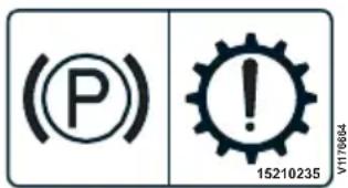
Decal for driveline shutoff via parking brake (positioned in the cab)

natural_image
Two abstract icons: a person silhouette and a gear, both without any text or symbols.Driveline shutoff via seat belt (positioned in the cab)
- The gear selector is in neutral position.
- The hand throttle is not actuated.
- The parking brake is applied.
- Regeneration (of Exhaust Aftertreatment System) is not activated (only valid for machines with D3.3H-engine).
When the conditions have been met and one minute remains of the predetermined time, a message is shown on the display unit.
The countdown for engine shutdown can be interrupted by actuating the accelerator pedal, hand throttle, or gear selector.
When automatic engine shutdown has taken place:
- The ignition key remains in position 1, running position.
- Lights or other connected current-consuming devices remain activated.
Driveline shutoff
(optional equipment)
Driveline shutoff via parking brake
The function prevents the machine from being driven unless the parking brake has been released. Unintentional driving with the parking brake applied and the associated increase in wear are therefore prevented.
Gear is forced to neutral if the parking brake is applied.
NOTE!
Apply the foot brake before releasing the parking brake.
Driveline shutoff via parking brake and seat belt
The function prevents the machine from being driven unless the parking brake has been released and the seat belt has been fastened. Unintentional driving with the parking brake applied and the associated increase in wear are therefore prevented.
NOTE!
Apply the foot brake before releasing the parking brake.
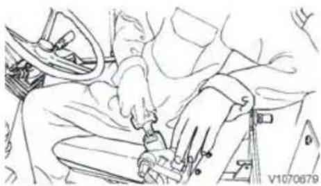
natural_image
Line drawing of a car interior showing hands adjusting a seatbelt (no text or symbols)
WARNING
Risk of personal injury or death.
If the parking brake is applied or the seat belt is unfastened during operation, the travel speed will be reduced inadvertently which may result in accidents.
During operation, the seat belt must remain fastened and the parking brake must not be applied.
NOTICE
Do not apply the parking brake while the machine is moving. The parking brake should only be used when the machine has been stopped or as an emergency brake.
Propeller shaft
The propeller shaft design is maintenance-free.
In extreme operating conditions, for example when the propeller shaft was taken unter mud and water accidentally, the propeller shaft can make noise during steering. Then, the propeller shaft may need to be lubricated. For further information, contact your dealer.
Visibility

WARNING
Risk of serious accidents.
Machine parts, equipment or load could obstruct the operator's view. Operating or driving with obstructed operator's view could cause serious accidents.
Use a signal man if operator's view is obstructed.
The following information applies to machines delivered to countries within the EU and may also apply to machines delivered to other countries outside the EU.
It may be impossible to obtain visibility to all areas around the machine. Optional devices and equipment such as warning systems, mirrors, back-
up alarm, and monitoring cameras (CCTV), etc., may be used to obtain acceptable visibility.
NOTE!
Some parts of the basic machine may restrict visibility, e.g., the cab's pillars and frames, exhaust pipe, engine hood, as well as optional equipment such as buckets, pallet forks, grapples, etc. The load that is handled with these attachments may also restrict visibility.
To minimize risks caused by restricted visibility, the management shall establish rules and procedures for the work site. For example:
■ Make sure that operators and persons on the site have received thorough safety instructions.
■ Conduct training for operators and staff on the site.
■ Control traffic flow for machines and other vehicles.
■ Restrict the machine's work area.
■ Use a signal man to assist the operator. Use hand signals according to the signal diagram, see page 162.
■ Make available equipment for two-way communication when needed.
■ Make sure that persons on the site communicate with the operator before approaching the machine.
■ Restrictions for maximum permitted speed as well as for reversing the machine over long distances.
Visibility standards to meet EU's machine directive
The standard ISO 5006 "Earthmoving machinery – Operator's field of view" deals with the operator's visibility around the machine and is intended to be used to measure and evaluate visibility. Conforming to this standard is a requirement in EU-countries and offers improved visibility around the machine.
- The machine is tested according to methods and criteria according to this standard. The method used to evaluate visibility cannot include all aspects of the operator's visibility, but gives information to determine if optional equipment for indirect visibility is necessary, e.g., warning systems.
- The test was performed on a stationary machine without load, with standard equipment and
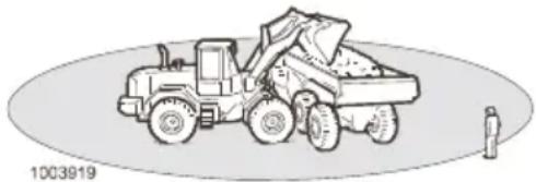
natural_image
Illustration of a front-end loader dumping material into a dump truck, with a person standing nearby (no text or symbols)The danger zone around operating machines is at least 7m (276 in).
standard attachment, and with the bucket in carry position.
■ ISO 14401 "Earthmoving machinery - Field of vision of surveillance and rear-view mirrors".
■ ISO 16001 "Earthmoving machinery - Hazard detection systems and visual aids - Performance requirements and tests" (Earthmoving machinery - Visibility using cameras).
If the machine is modified or retrofitted with other equipment or attachments, which result in reduced visibility, it shall be tested again according to ISO 5006, ISO 14401, and ISO 16001, and provided with optional visibility-enhancing equipment as needed.
Actions before and during operation
■ Walk around the machine and check that there are no obstacles next to the machine.
- Check that mirrors and other visibility-enhancing equipment is in good condition, clean, and properly adjusted.
- Check that the horn, back-up warning signal, and the rotating beacon (optional equipment) work correctly.
■ Check if the management has established rules and procedures for the work site.
■ Always keep a look-out and pay attention to the area around the machine so that any obstacles can be identified.
■ Prevent persons from entering or remaining in the danger zone, that is, the area around the machine and at least 7 m (276 in) beyond the attachment's maximal reach. The operator may allow a person into the danger zone, but then the operator must be very careful and only operate the machine when the person can be seen or has given clear indications of their whereabouts.
Safety rules when operating
Fuel, filling

WARNING
Risk of explosion!
The fumes in an empty fuel container are explosive.
Severe personal injury or death could result.
Keep open flames and sparks away from fueling area.
Do not smoke.
Never cut or weld on fuel lines, tanksor containers.
Safety procedures during refuelling
■ Turn off the engine and turn off all electrical switches, cab heaters, and the battery disconnector.
■ Do not refuel in enclosed areas.
■ Ensure that the refuelling area is well ventilated.
■ Do not refuel with the engine running.
■ Allow the engine to cool before refuelling.
■ Use handholds and steps provided to get to the fuel tank, if applicable.
■ Use care when removing the fuel tank cap.
■ To prevent static electricity sparks from igniting the fuel vapours, maintain good ground contact by keeping the fuel nozzle in constant contact with the fuel tank's filler neck.
Always ground the fuel nozzle against the filler neck to avoid sparks.
■ Do not mix gasoline or any other non-specified material with diesel fuel. Highly combustible vapours may result.
■ Use the correct fuel grade for the operating season.
■ Do not fill the fuel tank to full capacity.
■ Clean up any spilled fuel immediately.
■ Install and tighten the fuel tank's cap.
NOTE!
Should the fuel tank cap be lost, replace it only with a genuine manufacturer's approved cap. Using a non-approved cap without proper venting may result in pressurization of the fuel tank.
Operator obligations

WARNING
Risk of fatal accidents.
Unauthorised persons within the work area around the machine could lead to serious crushing injury.
- Clear all unauthorised personnel from the working area.
- Keep a lookout in all directions.
- Do not touch control levers or switches during start.
- Sound the horn before beginning operation.
■ The machine operator must operate the machine in such a way that the risk of accidents is minimized both for the operator, other road users, and persons present on the work site.
■ The machine operator must be thoroughly familiar with how to operate and maintain the machine and should preferably undergo required training on the machine.
■ The machine operator must follow the rules and recommendations given in the Operator's Manual, but also pay attention to any statutory and national regulations or specific requirements or risks that apply at the work site.
■ The machine operator must be thoroughly rested and must never operate the machine under the influence of alcohol, medicine, or other drugs.
■ The machine operator is responsible for the machine's load both when operating on public roads as well as when working on site.
- There must be no risk of the load falling off while operating.
- Refuse to take a load that is an obvious safety risk.
- Respect the rated load capacity of the machine. Note the effect of varying distances to the centre of gravity and the effect of additional units.
■ The machine operator must be in control of the machine's work area.
- Prevent persons from walking or standing under raised lift arms, unless they have been secured or supported.
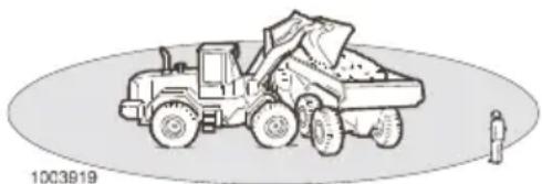
natural_image
Illustration of a front-end loader dumping material into a truck, with a person standing nearby (no text or symbols)The danger zone around operating machines is at least 7 m (275.5 in).
- Prevent persons from entering or remaining in the danger zone, that is, the area around the machine and at least 7 m (275.5 in) beyond the attachment's maximal reach.
■ The machine operator is responsible for the machine not being used to transport or lift persons, unless it is equipped and approved for this purpose. Contact a dealer for more information.
Accidents
WARNING
Risk of serious injury.
More than one person in the cab while operating could cause accidents and serious injury. Only the operator, seated in the operator's seat, may be in the cab when operating. All other persons must keep at a safe distance from the machine.
■ Accidents and also incidents should be reported to the site management immediately.
■ If possible leave the machine in position.
■ Only take necessary action so as to reduce the effect of damage, especially personal injuries. Avoid action which may make an investigation more difficult.
■ Take part in the emergency plan for the working site or other instructions about measurements in case of accidents.
■ Wait for further instructions from the site management.

natural_image
Line drawing of a person's hands operating a vehicle steering wheel (no text or symbols)Machine operator safety
■ Always use the lap-type seatbelt.
■ Always sit in the operator's seat with the seat belt fastened when starting the machine (engine) and when operating levers and switches.
- Check that the seat belt is not worn, see page 69.
■ The machine must be operational, i.e., defects that can cause accidents must be repaired.
■ Wear suitable clothing for safe handling and a hard hat.
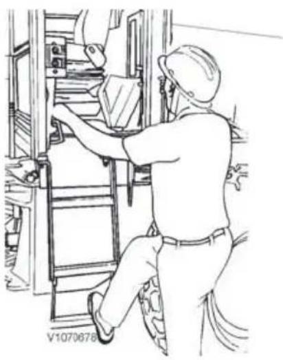
natural_image
Line drawing of a worker in hard hat operating machinery (no text or symbols)
Stepping surfaces
A Steps
B Anti-slip surfaces
■ A loose mobile telephone may not be used, as it may interfere with important electronics. The mobile telephone shall be permanently connected to the machine's electrical system and with a fixed aerial on the outside of the machine.
- Keep your hands away from areas where there is a risk of crushing, e.g., covers, door, and windows.
■ Use steps and handholds when entering or leaving the machine. Use the three-point stance, i.e., two hands and one foot, or two feet and one hand. Always face the machine – do not jump!
■ The door must be closed during work and transport operations.
■ The vibration (shaking) that occurs when operating may be harmful to the operator. Reduce this by:
- adjusting the seat and tightening the seat belt.
- choosing the smoothest operating surface for the machine (level the surface if needed).
- adapting the machine's speed.
The cab is for the protection of the machine operator and it meets the requirements for Roll Over Protective Structures according to the test standard (ROPS). Therefore, hold on firmly to the steering wheel if the machine should roll over – Do not jump!
■ The cab is also designed to meet the requirements for falling objects, the weight of which complies with testing methods according to "FOPS".
■ Only walk and stand on surfaces provided with slip-protection.
■ Do not enter or leave the machine during a thunderstorm.
- If you are outside the machine, keep a good distance away from the machine until the thunderstorm has passed.
- If you are in the cab, remain seated with the machine stationary until the thunderstorm passes. Do not touch any controls or anything made of metal.
- Check that the attachment is attached correctly and locked.

natural_image
Line drawing of a front-end loader dumping material into a pile (no text or symbols)
natural_image
Line drawing of a front-end loader with a person standing nearby (no text or symbols)
natural_image
Simple geometric diagram of a triangle with two internal dots, no text or symbols present.SMV-sign
■ The cab has one emergency exit, the rear window, which can be broken with the emergency hammer.
Operating on public roads
■ Road signs, barrier arrangements, and other safety devices that may be required when considering traffic speed, intensity, or other local conditions must be used.
■ When moving a machine with a suspended load, special attention must be observed. When required, a signal man must be used.
■ Rotating beacon may be used:
- on machine during road maintenance work, e.g., snow removal.
- on attached or connected implement that is wider than the machine itself.
- when the machine is an obstacle or danger to other traffic.
- when working on or by the side of the road.
- follow local rules and regulations.
Travelling on public roads
As a machine operator you are considered to be a road user and therefore required to know and follow local regulations and national traffic regulations.
It is important to remember that the machine, compared to other traffic, is a slow-moving and wide vehicle that may be an obstacle. Keep this in mind and pay attention to the traffic behind you. Facilitate overtaking.
■ SMV-sign (Slow-Moving Vehicle) shall be used. It should be placed in a position at the rear on the machine where it is clearly seen, not inside the rear window or any other window. It should be located at a height of 0.6–1.8 m (23.6–70.9 in) above the ground measured from the bottom of the sign.
■ The attachment should be empty, lowered to the transport position (30–40 cm (12–16 in) above ground) and fully tilted back.
■ The front end of the material handling arm must be marked with a red flag.
■ Lock the control levers with the control lever lockout.
■ All work lights and any rotating beacon should be off.

natural_image
Line drawing of a front-end loader and a car, no text or symbols present■ Hazard flashers may not be used except in emergency situations.
■ Attachments and buckets that restrict visibility must not be used.
■ Make sure that large attachments/buckets do not get in the way of the headlights. According to legislation, the machine's headlights must provide sufficient light and visibility in front of the machine.
■ Additional tools such as buckets, shovels, and iron bars must be thoroughly secured with tensioning straps or chains.
If a trailer is to be towed behind the machine, see page 116.
■ The connecting device on the counterweight must not be used when recovering, towing, or when operating on roads. Follow national regulations.
■ Comfort Drive Control (CDC) may not be used.
NOTICE
Follow national and state regulations.
Safety rules in case of fire
If your own safety is not at immediate risk, take the following actions.
In case of fire on the work site
1 If possible, move the machine away from the hazardous area.
2 Lower the attachment to the ground.
3 Turn off the engine by turning the start key counter-clockwise.
4 Leave the cab.
5 Open the engine hood and turn off the main electric power with the battery disconnector.
6 If possible, take active part in putting out the fire and call the fire department if needed.
In case of fire in the machine
If the machine is being operated:
1 If possible, park in a fireproof location.
2 Lower the attachment to the ground.
3 Turn off the engine by turning the start key counter-clockwise.
4 Leave the cab.
5 If possible, open the engine hood and turn off the main electric power with the battery disconnector.
6 Try to put out the fire.
7 Call the fire department if needed.

Power lines, minimum clearance

Risk of electrocution
Working near or making contact with overhead power lines may lead to electrical flashover and electrocution.
Always keep the minimum clearance from overhead power lines.
High voltage is lethal and could be powerful enough to destroy machine and attachments. Always contact the local authority before starting work near overhead power lines.
Operating the machine near overhead power lines requires special precautions.
■ Consider all overhead power lines to be energised with electric power, even lines that are supposed to be without electric power.
■ Contact with overhead power lines may cause a temporary power outage. The power may return automatically without any warning.
■ There is a risk of electrocution if anyone touches both the machine and the ground at the same time.
■ Always be aware of the very serious risk if the machine comes into contact with high voltage.
■ Remember that the voltage in the power line determines the safety distance.
■ Electrical flashovers may damage the machine and injure the operator at great distances from the power line.
■ Always keep the minimum distance from overhead power lines.
Minimum distance from overhead power lines
| Voltage of overhead power lines Volt (V) | Minimum distance | |
| m | ft | |
| up to 50,000 3 10 | ||
| 50,000 to 69,000 4 | 13 | |
| 69,000 to 138,000 5 | 16.4 | |
| 138,000 to 250,000 6 | 20 | |
| 250,000 to 500,000 8 | 26 | |
| 500,000 to 550,000 | 1 | 35 | |
| 550,000 to 750,000 | 1 | 43 | |
| more than 750,000 | 1 | 46 |
Know the location and voltage of all overhead power lines on the work site before operating the machine.
Contact the local authority if there is any question about the power lines being energised or their voltage.
Keep the following in mind to ensure safety when operating:
■ Know what to do if there is an electrical flashover that involves a person or machine.
■ Operate the machine at slower than normal operation speed when working near power lines.
■ Long-span power lines can sway and reduce the clearance.
■ Be careful when travelling over uneven ground which could cause the machine to become unstable.
- Keep all persons away from the machine whenever it is close to power lines.
■ Do not allow persons to touch the machine or its load before it is confirmed to be safe.
■ When a machine is in contact with an overhead line, do not allow anyone to come near or touch the machine. Stay away from the machine and call for help.
■ Never touch a person who is in contact with an energised power line.
If your machine comes into contact with overhead power lines:
■ Stay in the operator seat while the machine is in contact with the power line.
■ Warn personnel outside the machine to not touch any part of the machine and to stay away.
■ Stay in the operator seat and lower any raised parts in contact with the overhead power lines, or drive the machine away from the overhead power lines if it is possible.
If contact cannot be broken, stay in the operator seat until you know that the power is off.
If you need to get out of the machine to call for help or because of fire, jump out as far as you can without touching any wires or the machine, stay upright, keep your feet together and hop to safety.
Failure to follow this instruction could result in electrocution or death!
Measures before operating
1 Carry out daily service, see page 213.
2 Clean/scrape the windows.
3 Clean and adjust the mirrors.
4 Check that there are no faulty/loose parts or leaks which can cause damage.
5 Check that the battery disconnect switch is switched on.
6 Check that the frame joint lock has been disconnected.
7 Check that the wheels are not blocked.
8 Check that engine and access covers are closed and that the radiator casing is closed and secured.
9 Check that there are no persons in the vicinity of the machine, see page 82.
10 Adjust the operator seat (see page 67) and the steering wheel (see page 54).
11 Fasten the seat belt.
12 Check that there is sufficient fuel in the tank.
After operating
- Fill the fuel tank, as this will counteract the formation of condensation water.
■ Make sure that there is enough anti-freeze in the cooling system (see page 192) and in the washer fluid at temperatures below 0 °C.

natural_image
Circular diagram with concentric rings and a central vertical bar, no text or symbols present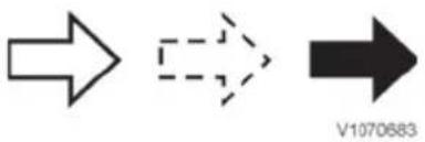
Air Lubrication oil Exhaust

A Exhaust inlet
B To exhaust system
C Air inlet
D Compressed air
Starting engine
NOTE!
The engine may only be started with the ignition in the cab.
If the machine is equipped with theft protection, see page 43.
1 Place the gear selector in neutral.
2 Turn the key in the ignition to operating position (1) so that the system test runs for 4–5 seconds.
3 At the same time, check that all lights turn on and that the gauges indicate readings.
4 Turn the key to start position (2). If the engine does not start, turn back the key to 0-position before trying to start again.
5 Check that all control lights and warning lights turn off.
6 Check that the attachment is fastened securely to the machine by pressing it against the ground.
7 Sound the horn.
8 Release the parking brake.
9 Select gear position and increase the engine speed.
Turbocharger
The turbocharger is lubricated and cooled by the engine's lubrication system.
Important for the turbocharger's function is that:
■ lubrication and cooling is safeguarded by
- not revving the engine immediately after start.
- letting the engine run at low idle rpm for at least 30 seconds before being turned off.
■ the engine oil and oil filter are changed at prescribed intervals.
■ the air cleaner is maintained, and that the exhaust system and lubrication oil lines seal tight.
The turbocharger must be overhauled or replaced immediately in case of noise or vibrations.
Work on the turbocharger must be done at a workshop authorized by Volvo.
Starting engine in cold weather

WARNING
Risk of explosion.
Spraying flammable starting aids into engine components could cause an explosion.
Never use starting aids while attempting to start the engine.
The preheating function is controlled by the engine ECU.
1 Turn the start key to operating position (1).
2 If there is a need for preheating it is activated automatically.
3 A symbol is shown in the lower left corner of the display unit to indicate that preheating is activated.
4 When the symbol turns off the engine can be started by turning the start key to start position (2).
- Let the engine run at low idle for 60 seconds so that the oil in the engine, transmission and hydraulic system is warmed up and circulates easily to provide adequate lubrication.
■ Revving the engine immediately after start may also compromise the turbocharger's lubrication and cooling, resulting in major risks of seized bearings.
NOTE!
Do not use the working hydraulics and transmission at full rpm until the hydraulic oil is warmed up.

Starting with booster battery
A Connecting positive (+) terminals
B Connecting from negative (-) terminal on booster battery to GROUND on machine
Starting with booster battery

WARNING
Risk of explosion.
Batteries could explode due to the current surge if a fully charged battery is connected to a completely discharged or frozen battery.
Do not boost start a machine with a completely discharged or frozen battery.
Check that the booster battery or other power source has the same voltage as the battery in the machine.
1 Make sure that no gear is selected.
2 Apply the parking brake.
3 Connect one of the booster start cables from (+) on the booster battery, to (+) on the battery in the machine.
4 Connect the other booster start cable from (−) on the booster battery to GROUND on the machine (e.g., the engine block).
5 Make sure that the battery disconnector is turned On.
6 Start the engine with the start key in the cab.
NOTE!
Do not disconnect the booster start cables at this time!
7 Leave the batteries connected for 5–10 minutes after engine start.
8 If the standard battery is heavily discharged, it may be that the alternator does not charge. Turn on a number of major power users to get the charging started, e.g., headlights, work lights, and preheating.
9 Disconnect the booster start cables in the reverse order to how they were connected.
10 Reinstall the terminal caps on the battery terminals.
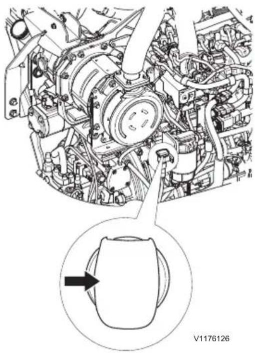
natural_image
Technical line drawing of a mechanical assembly with an inset showing a component detail (no text or symbols)Connection for engine block heater
Engine block heater
(Optional equipment)
This equipment is used to reduce the engine load that causes wear in the engine when it is started in areas with cold weather.
Braking
Brake smoothly. This is especially important when operating with a load and on slippery ground.
NOTICE
Do not apply the parking brake while the machine is moving. The parking brake should only be used when the machine has been stopped or as an emergency brake.
NOTE!
When the parking brake is operated the transmission will be forced into Neutral gear (optional equipment).
NOTE!
The high-speed machines feature overspeed monitoring to warn in case of overspeeding.
- When the speed equals or exceeds 32 km/h (19.9 mph), a warning message is displayed: "Reduce speed", and the buzzer will sound.
- Brake smoothly.
- The warning message will disappear as soon as speed has been reduced.

V 10931
Machine overspeed symbol

V1132419
Indicator lamp: Regeneration needed


V1130924
Red triangle and indicator for required regeneration

V1130926
Display message: Stop working, go to parked conditions
Exhaust aftertreatment system
Regeneration
NOTE!
This entire section is only valid for machines with D3.3H-engine.
The diesel particulate filter (DPF) is part of the exhaust aftertreatment system. The DPF traps 99% of soot and allows keeping maximum performance in every working condition.
When the soot content in the DPF has reached a certain level, the machine will request a DPF regeneration cycle to burn the collected soot. The DPF regeneration takes approximately 20 minutes. The regeneration requests will continue until regeneration is started and the levels will increase if regeneration requests are declined, see tables on following pages for details.
The time between DPF regeneration cycles depends on the machine work duty cycle.
If the machine is in a ventilated area which is free of flammable material, the operator should allow the machine to automatically start the regeneration process to prevent that service will be needed.
If the red triangle is visible in the display and regeneration is requested, a parked regeneration must be performed immediately in a safe area. If not, service will be needed.
Do not turn off the machine during the regeneration cycle unless there is an emergency.

CAUTION
Risk of thermal hazard.
The exhaust temperature is rising above the normal operation level during a regeneration. Make sure that the machine is in a safe environment during regeneration.
NOTE!
Using none ultra-low fuel will destroy the DPF. Using inappropriate engine oil quality will clog the DPF faster.

Indicator lamp: high exhaust temperature
NOTE!
During regeneration, the high temperature exhaust indicator turns on, indicating higher exhaust temperature compared to normal operation.
The machine should be in an area which is ventilated and free of flammable material when regeneration is in process. If the regeneration has started, indicated by this symbol, the operator should remain in the immediate vicinity of the machine to monitor the regeneration.
The high exhaust temperature indicator is alight during and after the regeneration until temperature falls below designated temperature range.
Active regeneration
NOTE!
The engine must be warm and not run on idle speed (engine speed should have minimum 1400 rpm) for a successful active regeneration!
Active regeneration means that the machine goes into the regeneration cycle automatically while operating. There is no loss of performance during active regeneration.
The machine will check for operator presence in the 60 seconds (1 minute) after the regeneration needed light turns on.
The operator can delay the process for 15 min by pressing the lower end of the Regeneration switch.
Parked regeneration
NOTE!
The engine must be warm before starting a parked regeneration!
Parked regeneration means that the operator chooses to run a regeneration when the machine is stationery in the parked position.
Following steps have to be taken:
1 Park the machine in a ventilated area which is free of flammable material.
2 Select neutral gear (no travelling direction selected).
3 Go to idle engine speed (no acceleration on pedal).
4 Apply the parking brake.
5 Press the upper end of the Regeneration switch to start the regeneration.
A parked regeneration will take longer and is less fuel efficient than an active regeneration.
Active regeneration with applied parking brake
NOTE!
The engine must be warm and not run on idle speed (engine speed should have minimum 1400 rpm) for a successful active regeneration!
If the parking brake is applied and the machine is requesting a parked regeneration there is a possibility to change to an active regeneration by increasing the rpm's above 1000 rpm.
The machine will check if there is an operator on the seat and start the active regeneration after 60 seconds (1 minute).
If the rpm's are coming below 1000 rpm during the active regeneration the machine will cancel the regeneration process and request a new regeneration after 15 minutes.

Regeneration switch
Delay regeneration
Regeneration can be delayed if the machine is in a non-suitable area with unsafe conditions or if you plan to stop the engine in less than 20 minutes.
Delay a regeneration by pressing the lower end of the Regeneration switch on the cab post panel.
Regeneration request message returns 15 minutes after a regeneration delay request.
Consequences of delaying regeneration
Delaying regeneration several times may lead to a situation where only a parked regeneration is allowed, see tables on following pages for details.
Cancelling regeneration in progress
NOTE!
Cancel a regeneration should only be done in the case of emergency or in unsafe conditions.
Cancelling a regeneration in progress could damage the system.
The throttle pedal will be unavailable during 30 second after cancelling regeneration in progress.
If the regeneration was cancelled, the regeneration needed indicator will still be visible in the display.
■ Press in the lower end of the Regeneration switch to cancel the regeneration.

Regeneration cancelled
V1130920
Text in information display:
Regeneration cancelled
Active regeneration is cancelled automatically:
■ when an engine malfunction occurs.
■ if the parking brake is applied.
■ if the machine is turned off.
■ if the regeneration is still running after 45 minutes. In that case a parked regeneration is requested after 15 minutes.
Parked regeneration is cancelled automatically:
■ when an engine malfunction occurs.
■ if parking brake is released or engine speed is changed with the hand throttle or accelerator pedal.
■ if the machine is turned off.
Long idle periods
Extended idling of the engine may cause the DPF to go through the various regeneration levels and shorten the life of the DPF filter. If there is not an operator in the cab to initiate the regeneration, the system could go to a “service needed” regeneration status where a qualified service technician would need to be called.


V1130924
Red triangle and indicator for required regeneration

Display message: Active regeneration will start soon

Display message: Stop working, go to parked conditions
Regeneration
When the soot content in the diesel particulate filter (DPF) has reached a certain level, the machine will request a DPF regeneration cycle to burn the collected soot.
When the regeneration's indicator lamp turns on, a regeneration depending on the conditions has to be performed early. Read the chapters "Conditions for active, parked, and service regeneration" and "Perform active or parked regeneration".
The high exhaust temperature indicator is alight during and after the regeneration until temperature falls below designated temperature range.

Indicator lamp: high exhaust temperature
Conditions for active, parked, and service regeneration
Conditions for active regeneration
- The display message is "active regeneration will start soon"
- You are in a ventilated area that is free of flammable material
- You will continue with your work for at least 20 minutes
If conditions are fulfilled, follow the instructions described in "perform active regeneration".
If conditions are NOT fulfilled, delay the regeneration by pressing the lower end of the regeneration switch. The regeneration request message will return every 15 minutes.
NOTE!
Delaying regeneration process several times will lead to following situations:
1 Engine power decrease.
2 Further engine power decrease: parked regeneration has to be done.
3 A service regeneration has to be done.
4 The DPF can be damaged and has to be exchanged.
Read the chapter "Consequences of delaying regeneration"
Conditions for parked regeneration
- The display message is "active regeneration will start soon" -> you CAN perform a parked regeneration, or
- The display message is "STOP working, Go to parked conditions" -> you MUST perform a parked regeneration soon to avoid the need of a service.


V1130924
Red triangle and indicator for required regeneration
NOTE!
If the red triangle is visible in the display and regeneration is requested, a parked regeneration must be performed immediately in a safe area. If not, service will be needed.
NOTICE
Risk of machine damage.
Neglecting request for regeneration of exhaust aftertreatment system could cause damage to the machine.
Start the regeneration at the earliest request stage possible.
If conditions are fulfilled, follow the instructions described in "perform parked regeneration".
NOTE!
In parked regeneration the engine speed will be automatically adjusted to the correct rpm.
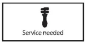
V1130929
Service regeneration needed
Conditions for service regeneration
The service regeneration has to be performed by a service technician.


V1091833
Regeneration switch
1 START of regeneration
2 STOP of regeneration in progress
Perform active or parked regeneration

CAUTION
Risk of thermal hazard.
The exhaust temperature is rising above the normal operation level during a regeneration.
Make sure that the machine is in a safe environment during regeneration.
Symbol for ongoing regeneration
NOTE!
■ The engine must be warm and not run on idle speed (min. 1400 rpm) for a successful active regeneration!
■ During regeneration, the high temperature exhaust indicator turns on, indicating higher exhaust temperature compared to normal operation.
■ The machine must be in an area that is ventilated and free of flammable material when regeneration is in process. If the regeneration has started, indicated by the regeneration symbol, the operator should remain in the immediate vicinity of the machine to monitor the regeneration.
It is important that regeneration is started as soon as possible and that the engine runs until the regeneration has been completed (when the light for high exhaust temperature has turned off). Full engine power can also be used if the regeneration is started immediately.
■ With low engine load and low outside temperature cab heating may have to be turned off to produce enough heat energy for a successful regeneration.
■ Do not turn off the machine during the regeneration cycle unless there is an emergency.
■ Using none ultra-low sulphur fuel will destroy the DPF, see 222.
■ Using inappropriate engine oil quality will clog the DPF faster, see 220.
Perform active regeneration
1 If necessary conditions are fulfilled, continue with your work (min. 1400 rpm).
2 Press upper part of regeneration switch (or just wait).
- Regeneration will start (automatically after 1 minute)
NOTE!
The operator's presence is mandatory for at least 60 seconds and will be checked by the machine!
- The operator can apply the hand break and leave the machine during active regeneration
- Regeneration will stop automatically after minimum 20 minutes (depending on temperature and rpm)
Perform parked regeneration
1 If necessary conditions are fulfilled, park the machine in a ventilated area that is free of flammable material.
2 Apply the parking break and let the machine low idle. Let the machine control the rpm itself.
- The display shows "Start parked regeneration".
3 Press the upper part of the regeneration switch to start the parked regeneration.
4 Do not use the machine during parked regeneration.
- Regeneration will stop automatically after about 20–40 minutes (depending on temperature).
5 Parked regeneration is aborted if:
- Parking brake is released
- Accelerator pedal is activated
- Process is stopped by pressing regeneration switch
NOTE!
The machine has to be observed during regeneration!
Delay regeneration
Regeneration can be delayed if the machine is in an area with flammable material or if you plan to stop the engine in less than 20 minutes.
Delay a regeneration by pressing the lower end of the regeneration switch on the cab post panel.
Regeneration request message returns 15 minutes after a regeneration delay request.
Consequences of delaying regeneration
There are five levels of regeneration notice depending on the soot quantity in the DPF. If regeneration is delayed, the soot quantity will increase and levels go from 1 to 5, see details in the following table.
| ConditionDisplay message (symbol and text) | Alarm level |
If operating (parking brake is not applied): Active regenerationwill start soonV1130923Active regeneration will start soon Active regenerationwill start soonV1130923Active regeneration will start soon | Level 1- Buzzer sounds 3 times- Alarm returns every 15 minutes if the regeneration is cancelled or until the next level is reached. |
If the parking brake is applied: Start parked regenerationV1131683Start parked regeneration Start parked regenerationV1131683Start parked regeneration | |
If operating (parking brake is not applied): Active regenerationwill start soonV1130923Active regeneration will start soon Active regenerationwill start soonV1130923Active regeneration will start soon | Level 2- Buzzer sounds 3 times- Alarm returns every 15 minutes if the regeneration is cancelled or until the next level is reached.- Engine power decreases (low derate) |
If the parking brake is applied: Start parked regenerationV1131683Start parked regenerationNot shown if the parking brake is applied after more than 60 s. Start parked regenerationV1131683Start parked regenerationNot shown if the parking brake is applied after more than 60 s. | |
If operating (parking brake is not applied): V1130926STOP WORKING Go to parked conditionWhen the parking brake has been applied: V1130926STOP WORKING Go to parked conditionWhen the parking brake has been applied: Start parked regenerationV1130927Start parked regeneration Start parked regenerationV1130927Start parked regeneration | Level 3- Buzzer sounds- Parked regeneration must be started immediately to avoid downtime and service regeneration- Buzzer turns off when regeneration is initiated.- Red central warning on- Engine power decreases significantly (high derate) |
When the parked regeneration is in progress: Do not use machine Regen. on-goingV1130928Do not use machine Regeneration ongoing Do not use machine Regen. on-goingV1130928Do not use machine Regeneration ongoing | During parked regeneration level 3. |
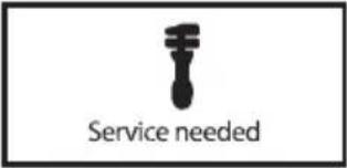 V1130929Service needed V1130929Service needed | Level 4- Buzzer sounds- Red central warning on- Engine power decreases significantly (high derate) |
 V1130929Service needed V1130929Service needed | Level 5- Buzzer sounds- Red central warning on- Engine power decreases significantly (high derate)NOTE!A service technician must be called to replace the DPF. |

Text in information display: Regeneration cancelled
Cancelling regeneration in progress
NOTE!
Cancel a regeneration only in case of emergency or if flammable material is present. The regeneration must then be restarted from the beginning.
If the regeneration was cancelled, the regeneration display message will still be visible.
■ Press the lower end of the regeneration switch to cancel the regeneration.
Active regeneration is cancelled automatically:
■ when an engine malfunction occurs.
■ if the machine is turned off.
Parked regeneration is cancelled automatically:
■ when an engine malfunction occurs.
■ if parking brake is released or accelerator pedal is pressed.
■ if the regeneration is still running after 45 minutes.
■ if the machine is turned off.
Long idle periods
Extended idling of the engine may cause the DPF to go through the various regeneration levels. If there is no operator in the cab to initiate the regeneration, the system could go to a “service needed” regeneration status where a qualified service technician would need to be called.
Perform a regeneration

CAUTION
Risk of thermal hazard.
The exhaust temperature is rising above the normal operation level during a regeneration.
Make sure that the machine is in a safe environment during regeneration.
Semiautomatic DPF regeneration mode
| Text in information display | Display figure Alarm level Action | ||
| Machine in working condition: “Active regeneration will start soon” |  V1132419 V1132419 V1130923 V1130923 | Level 1- Buzzer sounds (repeated 4 times)- Alarm returns every 15 minutes | The regeneration will start after 1 minute, unless the Regeneration switch is pressed to delay it or if there is no operator on the seat.NOTE!Pressing the ESC button removes the display message but does not cancel the regeneration.NOTE!If conditions are changed from working to parked (1), the active regeneration will be cancelled and the machine will request a parked regeneration. |
| Machine in parked condition: “Start parked regeneration” |  V1132419 V1132419 V1131983 V1131983 | 1 Park the machine in a safe environment. Apply the parking brake.2 Press the upper end of the Regeneration switch to start the parked regeneration.NOTE!If the conditions are changed from parked to working(2), an active regeneration will start soon, see description above. | |
- Parked condition: parking brake applied, transmission in neutral and rpm on idle.
- Working condition: operator on the seat and one of the parked conditions not met.
| Text in information display | Display figure Alarm level Action | ||
| Machine in working condition: “Active regeneration will start soon” |  | Level 2- Buzzer sounds (repeated 4 times)- Alarm returns every 15 minutes- Engine power decreases (low de-rate) | The regeneration will start after 1 minute, unless the Regeneration switch is pressed to delay it or if there is no operator on the seat.NOTE!Pressing the ESC button removes the display message but does not cancel the regeneration.NOTE!If conditions are changed from working to parked (1), the active regeneration will be cancelled and the machine will request a parked regeneration. |
| Machine in parked condition: “Start parked regeneration” |  | 1 Park the machine in a safe environment. Apply the parking brake.2 Press the upper end of the Regeneration switch to start the parked regeneration.NOTE!If the conditions are changed from parked to working, the parked regeneration is cancelled and an active regeneration will be requested, see description above.NOTE!If the conditions are changed from parked to working(2), an active regeneration will start soon, see description above. | |
| “STOP WORKING Go to parked conditions”“Start parked regeneration” |   V1130924 V1130924 V1130926 V1130926 V1130927 V1130927 | Level 3- Buzzer sounds- Buzzer turns off when regeneration is initiated.- Red central warning on- Engine power decreases significantly (high de-rate) | 1 Park the machine in a safe environment. Apply the parking brake and go to idle.2 Press the upper end of the Regeneration switch to start the parked regeneration.NOTE!Regeneration is cancelled if the parking brake is deactivated. Regeneration must be completed before continuing operation. |
| “Do not use machine Regeneration ongoing” |   V1130924 V1130924 V1130928 V1130928 | During parked regeneration in level 3. | NOTE!Wait until the message and the indicator for high temperature disappear and the engine is back at low rpm. |
| “Service needed” |   V1130924 V1130924 V1130929 V1130929 | Level 4- Buzzer sounds- Buzzer turns off when regeneration is initiated.- Red central warning on- Engine power decreases significantly (high de-rate) | 1 Park the machine in a safe environment.2 Turn off the engine.3 Contact a service technician for regeneration.NOTE!Regeneration is only possible with Volvo Construction Equipment's service tool. |
| “Service needed” |   V1130924 V1130924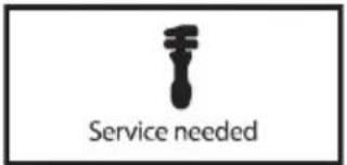 V1130929 V1130929 | Level 5- Buzzer sounds- Red central warning on- Engine power decreases significantly (high de-rate) | 1 Park the machine in a safe environment.2 Turn off the engine.3 Contact a service technician to replace the DPF. |
Stopping
NOTICE
Do not turn off the battery disconnect switch when the engine is running. The electrical system may be damaged.
1 Reduce engine speed.
2 Brake the machine to a stop and shift to neutral.
3 Lower the attachment to the ground.
4 Apply the parking brake.
NOTE!
It is important to run the engine at low idle rpm for at least 30 seconds before turning it off to make sure that the turbo receives adequate lubrication and cooling.
NOTE!
It is important to not cancel a regeneration and immediately turn off the engine in order to avoid unnecessary heat stress on components under the engine hood. Wait until the light for high engine exhaust temperature has turned off.
5 Turn off the engine.
If the operator has to leave the cab with the engine running, exit carefully to avoid turning the steering wheel inadvertently as the operator leaves the cab. This applies particularly if the steering wheel is provided with a knob.
NOTICE
Use handholds to access the cab. Always use the 3-point approach to access or leave the cab, i.e. two hands and one foot.

natural_image
Line drawing of a worker in hard hat climbing an elevator ladder (no text or symbols)
V1070691
Parking
1 If possible, place the machine on level ground. If this is not possible, block the wheels so that the machine cannot start rolling. Lower the attachment against the ground.
2 Check that all switches and controls are in the "off" position or in neutral.
3 Apply the parking brake after the machine has come to a complete standstill.
4 Remove the keys.
5 Turn off the electric power with the battery disconnector, if the machine is to be left unattended for some time.
6 Make sure that there is enough anti-freeze in the cooling system (see page 220) and in the washer fluid at temperatures below 0 °C when parking.
7 Lock all covers, engine hood, windows and the door.
Remember that the risk of theft and break-in can be minimized if one:
- removes the ignition key when the machine is left unattended.
- locks all covers, engine hood, windows and the door after end of the working shift.
- turns off the electric power with the battery disconnector and removes the handle.
- avoids parking the machine in places with high risk of theft, break-ins and malicious damage.
- removes all valuable items from the cab, e.g., mobile telephone, computer, radio, and bags.
It is easier to identify stolen machines if PIN-number or registration number is etched onto the windows.
Long-term parking and taking machine out of service
NOTICE
If the machine is not going to be used every day, all cylinders should be protected against corrosion.
■ The temperature may not be below -40 °C or above +70 °C.
■ Check that the batteries are fully charged.
- Carry out the measures as described above.
■ Wash the machine and touch up any damaged paint finish to avoid rusting.
■ Treat exposed parts with rustproofing, lubricate the machine thoroughly and apply grease to unpainted surfaces (lift and tilt cylinders, etc.).
- Fill the fuel tank and the hydraulic oil tank to the max. marks.
■ Cover the exhaust stack (parking outdoors).
■ Remove the fuse for the voltage converter and radio. Otherwise there is a risk that the batteries will be discharged.
■ Check the tire inflation pressure and protect the tires against strong sunlight.
Check after long-term parking and after machine has been out of service
■ All oil and fluid levels
■ Tension of all belts
■ Tire inflation pressure
Air cleaner
■ Install the fuse for the voltage converter and radio
NOTE!
If any protective agents (rustproofing, etc.) have been used on the machine to prepare for long-term parking, follow the manufacturer's instructions for safety measures and methods for removing.

(Principle illustration)
Measures when getting stuck
What to do if the machine gets stuck
If the machine has gotten stuck, it is usually best to reverse out. If you cannot reverse or move forward, try the following:
1 Engage the differential lock.
2 Select 1st gear.
3 Reverse and alternate steering the machine to left full lock and then to right full lock ("duck walk").
If only the front wheels have become stuck, proceed in either of the following ways:
1 Lift the front wheels, supporting the machine on the floor of a flat bucket, and reverse.
2 Steer to the right or to the left, press the bucket against the ground, lift up the front wheels and steer the other way, raise the bucket slightly and reverse.
3 Lift up the front wheels using the bucket. Manually fill the holes under the wheels with branches, pieces of wood, or similar, and reverse.
4 If the machine needs to be recovered, see page 116.
NOTE!
The propeller shaft may need to be lubricated, see page 79.
NOTE!
Respect the operating instructions for differential lock, see page 54.
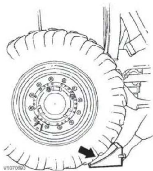
natural_image
Technical line drawing of a tire assembly with mounting holes and a directional arrow indicating motion (no text or symbols)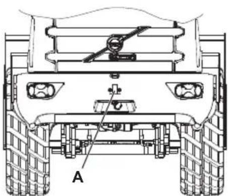
natural_image
Technical line drawing of a vehicle rear view showing front, side, and top views with labeled component 'A' (no text or symbols beyond label)V1132351
A Tow hitch (for recovering backward)

natural_image
Technical line drawing of a vehicle chassis with visible tire, suspension components, and mounting brackets (no text or symbols)Lashing points (for recovering forward)
Retrieving and towing
WARNING
Risk of runaway machine.
Improper recovering or towing methods or faulty equipment could cause the machine to break away from the towing vehicle, causing accidents, serious injury or death.
Always apply parking brake and block the wheels to prevent the machine from moving while attaching the towing equipment.
NOTE!
The towing hitch at the rear end of the machine must not be used to tow a trailer.
Actions
If possible, the engine should be running so that the brakes and steering work.
Recovering
Use a towbar or other suitable tools to pull the machine to a suitable location or passable road.
■ When recovering backward, use the tow hitch (A) on the counterweight.
■ When recovering forward, use the two lashing points on the front frame.
Maximum total force when recovering:
- Backward: 40 kN (8992 lbf)
- Forward: 40 kN (8992 lbf)

natural_image
Line drawing of two heavy construction vehicles pulling a road, no text or symbols present(Principle illustration)
Towing
The towing vehicle or machine must weigh at least as much as the machine that is to be towed, and it must have sufficient engine power and braking capacity to pull and brake both machines on any uphill or downhill grades.
NOTICE
Always use personal protective equipment, such as working gloves, overalls and face protection or protective goggles with side protection before you release excess pressure in a hydraulic hose or pipe connection.

A Test port
B Test port
C Hose (found in tool box)
■ Make the following preparations before towing the machine:
1 Apply the parking brake and turn off the engine.
2 Open the engine hood to access the test ports on the left side in the engine compartment.
3 Loosen the test nipple caps from the test ports (A and B).
4 Connect the hose (C) (found in the tool box) between A and B.
■ Select neutral gear and release the parking brake before towing.
■ If possible, the engine should be running so that the brakes and steering work.
■ The machine should not be towed for a longer distance than absolutely necessary since otherwise the transmission may be damaged.
■ Towing should be limited to a speed of max. 2 km/h (1.25 mph) and a distance of 1 km (0.625 mile).
NOTE!
For longer distances the machine must be transported on a transport vehicle or trailer.
■ Connect in the corresponding way as when recovering.
NOTE!
It is not possible to start the engine by towing.
Follow national regulations where required.
After towing
NOTE!
Disconnect the hose and close the test nipple caps on the test ports.

natural_image
Technical line drawing of a vehicle chassis with labeled components (A), no readable text or symbols beyond labelTow hitch on counterweight
Before the towbar or wire is removed, the following safety actions should be taken:
1 If possible, place the machine on level ground.
2 Apply the parking brake or block the wheels to prevent the machine from rolling.
Tow hitch on counterweight
Maximum temporary force on the tow hitch (towbar) on the counterweight including attachment bracket must not exceed a horizontal force of 40 kN (8992 lbf) and a vertical force of 4 kN (899 lbf).

natural_image
Side profile illustration of a front-end loader (no text or symbols)Transporting machine
NOTICE
The person in charge of the transport must see to that loading, positioning, lashing and transporting the machine on a trailer or other vehicle is done according to applicable laws and regulations for the country or state in question. For further information, contact your dealer.
V1131735
A Lashing points
B Block the wheels

V1132360
Frame joint lock
A Lock bolt (in lock position)
B Lock pin
C Lock bolt (in stowed position)
On another vehicle
If the machine is lifted up onto another vehicle, the frame joint must be locked.
- Use the intended lifting points for any lifting, see figure.
- Lock the frame joint with the lock bolt (A) and lock pin (B).
If the machine is driven up onto another vehicle, the frame joint must not be locked.
■ The frame joint must be locked when the machine has been driven up on the trailer and reached final position.
■ Tie down (lash) the machine.
Tying down machine
■ Block the wheels (B).
■ Tie down (lash) the machine using the intended lashing points (A) so that the machine cannot tip or begin to roll.
Across ramp
■ First check that the ramp is wide enough, that it has the required strength, and that it cannot be displaced.
In elevator or other confined space
1 Reverse the machine in.
2 Apply the parking brake and turn off the engine before starting the elevator.
In addition, ensure national or state regulations are followed.
Securing cargo (machine) that has been loaded
See the following conditions for securing a machine that has been loaded.
Conditions for securing cargo
■ The machine is subjected to a max. acceleration of; 0.8 g forward, 0.5 g backward, 0.5 g sideways, and 0.2 g upward. (1)
■ Acceleration forward, backward, and sideways act individually and they are combined with 1 g downward. (1)
■ Acceleration upward is not combined with other accelerations. (1)
A safety factor of 1.25 has been used to compensate for uneven distribution of forces in the lashings. The arrangement can also withstand an acceleration of 1 g forward without safety factor. (1)
■ The machine (with or without attachment) is manufactured by Volvo Construction Equipment.
■ The machine has new or normally used rubber tires or wood-covered rims of pine or birch. If the wood-covering is made of birch, then rubber spacers shall be used between wood-covering and ground surface for the friction 0.5. If rubber spacers are not used the friction is only 0.2.
■ The machine stands centred sideways ( ± 5 cm (2 in)) and is supported on at least half of the tires' width.
■ The parking brake is applied and functional, and can handle an inclination (grade) of at least 14irc .
■ The frame joint is locked.
■ The machine is loaded and secured in such a way that no parts, i.e., painted surfaces or tires, can be damaged.
■ The machine is loaded on a vehicle with a trailer bed made of wood, plyfa (plywood), grooved aluminium plates, unpainted or painted steel plates.
■ The distance sideways between tie-down points on the load-carrying transport vehicle is approx. 2,500 mm (100 in).
■ The lashings are pre-loaded to at least 4,000 N during the whole transport.
■ The tie-down points on the trailer have at least the same breaking strength as the lashings.
■ The lashings are located symmetrically in pairs and are fastened in the intended tie-down points on the machine. Only one lashing shall be fastened to each tie-down point.
It shall not be possible for the tie-down hooks to lose their grip if the lashings become slack.
■ Safe loading in the chain (MSL/LC/SWL) is at least 50% of the breaking strength (MBL).
■ Dampers should be used when short, vertical lashings are used on machines with rubber tires to reduce the jerking and shocks to which the chains may be subjected.
■ When using blocks, these must be well fastened, have an angle of approx. 37irc (3:4:5), a height of at least 25 cm (10 in), and be located in pairs; 1, 2, 3, or 4 pairs according to above tables with block placement.
- Placement of rubber tires/wood-covered rims against wheel slots corresponds to the use of blocks.
■ Blocking of the bucket, lifting device, back of the machine, or the wheel pairs turned in the travel direction with at least half of the steering wheel radius against the swan neck or corresponding direction forward, prevents forward movements.
■ Blocking of adequate height acting on the inside or outside of all four wheels prevents sideways movement.

Lifting points and lengths
A 5 meter (197 in)
B 2 meter (79 in)
C 6,5 meter (256 in)
Lifting machine
1 Lock the frame joint.
2 Lift the machine in the intended lifting eyes (see figure).
Operating techniques
The following pages contain advice and instructions on how to operate the machine and examples of how the most common attachments are used. It is important that the correct operating techniques are used to carry out the work in a safe and efficient way.
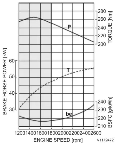
line
| ENGINE SPEED [rpm] | BRAKE HORSE POWER [kW] | TORQUE [Nm] | BSFC [g/kWh] | | ------------------ | ---------------------- | ----------- | ------------ | | 1200 | 25 | 200 | 210 | | 1400 | 26 | 210 | 220 | | 1600 | 27 | 220 | 230 | | 1800 | 26 | 230 | 240 | | 2000 | 25 | 240 | 250 | | 2200 | 24 | 250 | 260 | | 2400 | 23 | 260 | 270 | | 2600 | 22 | 270 | 280 |Economical engine speed (grey area)
- = P = Power
- = T = Torque
- = be = Fuel consumption
Eco driving
Low engine rpm should be maintained in all handling for optimal use of the system and minimal fuel consumption. Exceptions are:
- when filling the bucket, here engine rpm should be adapted to the material's resistance.
- during the acceleration phase in longer work cycles, e.g., load-carry. When transport speed is reached, ease off on the throttle.
Lift speed and power are sufficient already at low engine speed, which gives lower fuel consumption, lower sound level, and higher comfort with maintained high productivity.
A fuel-saving way of operating also means less machine wear and that you spare the environment.
Always strive to:
■ Remain within the economical rpm range High engine rpm seldom means higher productivity, but most often higher fuel consumption. When filling the bucket, the rpm should be adapted to the material's resistance and during the acceleration phase in longer work cycles (e.g., load-carry) high throttle application can be used until transport speed is reached.
■ Adapt operating method to the application Follow the recommendations for the applications included in the chapter.
■ Select attachment for the application Using attachments made for the application can boost productivity at the same time as fuel consumption and machine wear are reduced. Follow the recommendations in the chapter.
■ Maintain correct air pressure in tires On page 240 there are recommendations for air pressure in tyres. Maintaining correct air pressure in tires reduces fuel consumption and machine wear.
■ Do not let the machine idle unnecessarily However, follow recommendations for turning off the engine, see page 112 to ensure lubrication of the turbocharger.
■ Plan the work site
Assess and plan your work site and its layout based on the machines that are going to work there, this will make work more organized and
effective. Keep the ground surface smooth and free from big stones and other obstacles.
■ Cooperate
Cooperate with other operators to enable maximal efficiency and effectiveness when working with the machines.
Contact your dealer for more information and for an opportunity to participate in a Volvo course within the area.
Whole-body vibrations
Whole-body vibrations generated by construction machines are influenced by a number of factors, such as work methods, ground conditions, and machine speed, etc.
The operator can affect the actual vibration levels to a great extent, since it is the operator who controls the machine's speed, work method, and haul route. Therefore, the result can be a range of different vibration levels for the same type of machine. For cab specifications, see page 242.
Guidelines for reducing vibration levels for earthmoving machines
■ Use the proper type and size of machine, with tires, optional equipment and attachments for the application.
- Keep the ground and haul roads in good condition.
- Remove any large rocks or obstacles.
- Fill any ditches and holes.
- Provide equipment and schedule time to maintain ground conditions.
■ Adjust speed and haul route to minimize vibration levels.
- Drive around obstacles and rough ground conditions.
- Reduce the speed, if it is necessary to travel across uneven ground.
■ Maintain machines according to the manufacturer's recommendations.
- Tire pressure
- Brake and steering systems.
- Operating controls, hydraulic system, and linkage.
■ Make sure that the operator's seat is maintained and correctly adjusted.
- Adjust the seat and its suspension according to the operator's weight and height.
- Check and maintain the seat suspension and adjustment mechanisms.
- Use the seatbelt and adjust it correctly.
■ Steer, brake, accelerate, shift gears, and operate the attachments smoothly.
■ Minimize vibrations for long work cycles or long-distance travel.
- Use Boom Suspension System if the machine is equipped with such a system.
- If the machine is not equipped with a Boom Suspension System, reduce speed to prevent bouncing and rocking.
- Transport the machine when there are long distances between work sites.
Backpain, suspected of originating from whole-body vibrations, may be caused by other risk factors. The following guidelines can be effective in minimizing risks of backpain:
- Adjust the seat and operating controls so that good posture is obtained.
- Adjust the mirrors to minimize twisting of the body.
- Plan for and take breaks in order to avoid long periods of sitting still in one position.
- Do not jump down from the machine.
- Minimize repeated handling and lifting of objects.
Working within dangerous areas
■ Do not operate too close to the edge of a dock, ramp, etc.
■ Operate slowly in tight spaces and check that there is enough room for machine and load.
■ Operating under ground requires special equipment, e.g., certified engine within the EU and EEA-countries. Talk to your dealer.
■ Use the machine's lights when working in poor light conditions, e.g., indoors and in tunnels.
■ The machine must be specially equipped when operating and working in a contaminated environment or health-hazardous area. Talk to your dealer. Also check the local regulations before you enter the area with the machine.
Underground cables and pipes
Make sure that authorities or companies responsible for cables and pipes have been contacted and that their instructions are followed. Also check which rules apply to ground personnel regarding exposing cables and pipes. Normally only the service companies' own personnel may expose and arrange provisional suspension of cables.
Make use of a signal man when you cannot see the actual point where you are working or when the position of the pipe or cable is critical, see page 162. The position of the pipe or cable may deviate from the drawing or distances may be incorrectly determined. Regard all electrical cables as live.
Working on slopes

WARNING
Risk of injury or death.
Machine could become unstable while operating on slopes or steep grades resulting in loss of control, tipover or rollover.
Operate machine up or down slope. Avoid turning and operating across the slope. Exercise extreme caution when working on a steep grade.
■ When working on a slope or grade, pay attention to the current weather and ground conditions in order to not jeopardize safety.

Maximum permitted angle
A Machine affected in fore-aft direction
B Machine affected sideways
■ Be careful when opening the door since it may be difficult to control with the machine leaning at an angle. When closing the door, make sure that it closes completely.
■ Operate slowly when approaching or running down a grade.
■ Do not operate faster down a grade than the machine can run up the grade.
■ Do not change travel direction when operating on a slope, and do not operate across a slope.
If the machine slides, lower the bucket to the ground immediately. The machine may roll over if it becomes unbalanced. Do not turn with a load in the bucket if the machine does not stand completely stable. If absolutely necessary, pile up earth material on the slope so that the machine can be parked on a level and stable surface.
■ If the engine stops when the machine is on a slope, lower the attachment to the ground.
NOTICE
Follow the recommendations for maximum permitted angle in the table below. Machine function may be compromised, e.g., lubrication, if recommendations are not followed. This may result in machine damage.
Maximum permitted angle
See the figure to the left to see how each angle (A and B) affect the machine.
| Machine affected in fore-aft direction (angle A) | Machine affected sideways (angle B) | ||
| Continuous effect | Temporary effect | Continuous effect | Temporary effect |
| A = 15°=A = 25°=B = 10°=B = 20° | |||
Working in water and on boggy ground
Do not exceed the maximum permitted water depth, reaching the lower foot step.
NOTICE
Check the water depth before taking the machine into the water.
NOTICE
The water may not reach over the bottom edge of seals for hubs, propeller shafts, and rear axle oscillation bearing.
NOTE!
The propeller shaft may need to be lubricated, see page 79.
When crossing a body of water with the machine, the water level may not reach higher than the wheel hub's centre. Pay attention if the water is turbid or cloudy, there may be hidden obstacles or dangerous deep hollows in the bottom. Refrain from operating in the area if you are not certain that it is safe to do so.
■ After working in water, the grease points that have been under water must be greased to force out any water.
- Check that no water has penetrated the transmission or axles.
Working where there is risk of landslip
Always check the ground conditions before beginning to work. If the ground is soft, great care must be taken when positioning the machine.
Thawing of frozen ground, rain, traffic, piling and blasting are factors which increase the risk of landslip. The risk also increases on sloping ground.
- Do not operate too close to the edge of a steep slope or road bank. Take care when working in a place where the machine may tip.
■ Take care when working on river banks or in other similar places where the ground is soft. There is a risk that the machine, because of its own weight and own vibrations, may sink and this could lead to accidents. - Keep in mind that the ground conditions may have changed after heavy rain. Therefore, be careful when restarting work. This is particularly important when working near the edge of ditches, road verges or similar, as the ground may easily give way after it has been raining.
Working in cold weather

WARNING
Risk of crushing injury.
The hydraulic system could respond slowly at low temperatures and could cause unexpected machine movements.
Operate carefully until the hydraulic system has reached operating temperature.
Read the advice for start, see page 93.
The windows should be free from ice and snow before starting to use the machine. Acceptable visibility is always a 'must have' condition, see page 79.
■ Watch out for slippery parts on the machine. Only step on slip-protected areas.
■ Use an ice scraper to remove ice from the windows. If needed, use a scraper with a long handle or a ladder.

WARNING
Risk of frostbite.
Bare skin can freeze stuck to cold metal which could cause injury.
Use personal protective equipment when handling cold objects.

DANGER
Risk of electrical shock.
Personal injury results if a body part comes into contact with a machine that conducts electric power.
Disconnect the electrical engine heater before working on the machine.
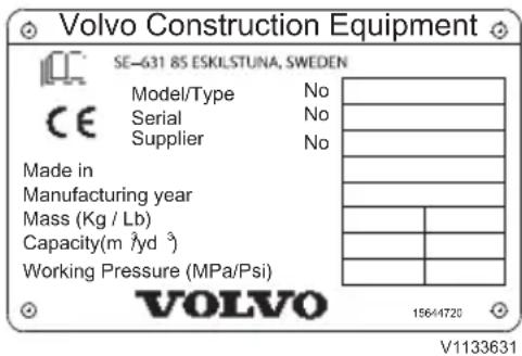
Shall be fastened on, e.g., attachment bracket, log grapple, log fork, material handling arm (CE-marking)

Shall be fastened on, e.g., attachment bracket, log grapple, log fork, material handling arm, and pallet fork frame

Shall be fastened on, e.g., bucket with hydraulically operated moving parts (side-tip and high-tip function), and bucket with thumb (clamping arm) (CE marking)
Attachments
WARNING
Risk of fatal accidents.
Using attachments for lifting or transporting persons may lead to fatal accidents with serious crushing injury or death.
Never use attachments for lifting or transporting persons.
Using the correct attachment for a particular job is a deciding factor when it comes to the capacity of the machine. The machine has either a pin-on attachment or a hydraulically operated attachment bracket, which allows rapid changes of attachments.
Follow instructions in the Operator's Manual.
According to EU's machine directive there shall be a CE-marking on the machine's product plate (see figures) as well as a "Declaration of conformity". This marking also covers attachments designed by Volvo and adapted for Volvo wheel loaders since they are an integrated part of the machine and adapted to the machine.
Attachments in the category "interchangeable equipment" 1) (attachments that can be changed by operator) designed by Volvo are CE-marked and adapted for Volvo wheel loaders and are supplied with a "Declaration of Conformity" as well as instructions.
The machine owner is responsible for the attachments being approved for installation on the machine. The machine owner is responsible for the safety of the combination machine – attachment.
For more detailed information about selecting attachments, contact a Volvo dealer to get a copy of the attachment catalogue.
The machine is prepared for different attachments. In order to connect these hydraulically to the machine, the hydraulics must first be depressurized, see page 140.
The machine's stability may vary depending on the attachments and the density of the material.

Both pin-on and hook-on. Shall be fastened on all buckets without hydraulically operated moving parts. This plate is for general use
1) "Interchangeable equipment" (attachments that can be changed by operator) means that the attachment requires the combination hydraulic attachment lock and together with hydraulic attachments, for example, a log grapple, a 3rd hydraulic function is needed, and in some cases also a 4th hydraulic function.
Transporting attachments with another vehicle
Follow the tie-down/lashing instructions according to standard SS-EN 12195-1, as well as local transport rules.
Rotating attachments
Hydraulically powered, rotating attachments
If the machine is used with hydraulically powered, rotating working parts, e.g., sweeper, brush mower, sand spreader, etc., the following general safety rules must be followed:
■ Installation of such an attachment for the first time may only be performed by a trained technician.
- Read, understand, and follow the instructions supplied with the attachment.
■ Always stop (turn off the hydraulic flow) the rotating/moving part of the attachment before leaving the cab.
■ When servicing or maintaining the attachment, or in case the working parts have come to a standstill while operating, the hydraulic hoses to the attachment must be disconnected in order to prevent accidental engagement of the hydraulic power, which might result in an accident.
Check that the attachment in question is CE-marked, if the attachment is not made by Volvo.
Make sure that your dealer includes in writing such an attachment in the "Declaration of Conformity" for your machine as being an approved attachment.
NOTE!
To avoid accident risks, before installing a hydraulically powered attachment, always get information on safety rules and safe handling from the manufacturer - BEFORE using such an attachment.
Attachment brackets
Tiltable rear attachment bracket
NOTE!
The safety regulations and information on travel operation and maintenance are described in the general operating instructions.
Mount salting attachment on the rear mounting, connect hydraulic and electrical connections.

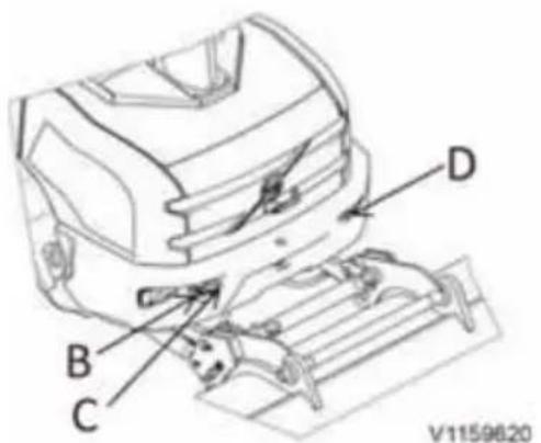
A Mountings
B Pressure line (max. 200 bar/ 30 l/min)
C Return flow line
D Socket for salting attachment lighting
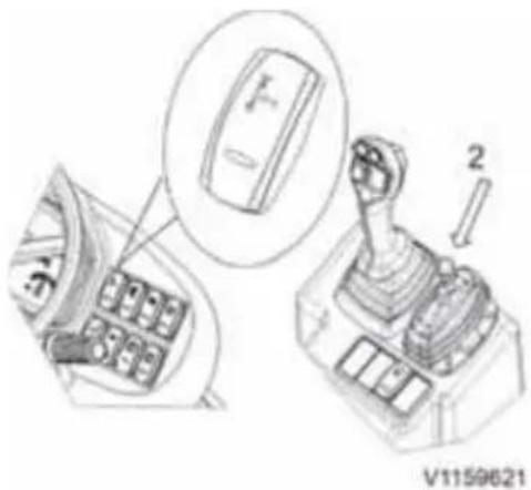
Loading process
1 Remove salting attachment lighting.
2 Pull the bolt at the rear mounting (A).
3 Switch on the tilting switch (arrow), move lever (2) forward and tilt the rear mounting slightly back.
4 Hook on the salting attachment (like a bucket).
5 Put the bolt back (A).
6 Tilt salting attachment in loading position.
7 Load salting attachment by driving in reverse.
8 Move lever (2) backward and tilt the salting attachment back into "salting position".
9 Switch off tilting switch.
The amount of salt is regulated by the engine speed. The optimum engine speed depends on the
desired amount of salt and can be found in the manufacturer's instructions.
NOTE!
When operating on a public road with full salting attachment, a front attachment which is heavy enough and the counterweight on the lifting frame must always be mounted so that the required load on the front axle is at least 20% of the total weight. When not performing winter service, the salting mountings must be disassembled and the counterweight which is supplied with the attachment must be mounted.
Maintenance
■ Check hydraulic lines at regular intervals for leaks and visible external damage, replace if necessary.
■ Grease the bearings and the cylinders of the rear mounting (for quality of grease refer to the lubricant table).
■ Always relieve the pressure in the hydraulic system before starting maintenance or repair work.
■ Work in hydraulic system must only be performed by authorized personal.

line
| Label | X-axis (mm) | Y-axis (kg) | | :--- | :--- | :--- | | C | 1000 | 250 | | C | 1400 | 220 | | C | 1800 | 190 | | C | 2200 | 160 | | C | 2600 | 130 | | C | 3000 | 100 | | C | 3400 | 70 | | C | 3800 | 40 | | C | 4200 | 20 | | C | 4600 | 10 | | D | 1000 | 50 | | D | 1400 | 40 | | D | 1800 | 30 | | D | 2200 | 20 | | D | 2600 | 10 | | D | 3000 | 5 | | D | 3400 | 2 | | D | 3800 | 1 | | D | 4200 | 0.5 | | D | 4600 | 0.25 | | D | 5000 | 0.125 | V1159622Maximum allowed load for quick coupler attachments rear
A Load (kg)
B Distance to rear axle (mm)
C Load with counterweight.
D Load without counterweight.
Separate attachment locking

WARNING
Risk of crushing!
Attachments that move unexpectedly can cause injuries.
Make sure people stay out of the working area when connecting or disconnecting attachments.

WARNING
Risk of crushing.
Unlocked attachments could become loose and fall and cause serious injury.
Always make sure the attachment is locked before operating. Be aware of controls that could unlock and release attachments.
Connecting
1 Press in the upper part of the separate attachment lock switch, and while the switch is pressed in, push control lever 2 (version 1A) or right roller control (version 1B) forward in order to retract the lock pins.
2 Tilt forward approx. 15irc and hook on the attachment.
3 Raise the lift arms until the attachment is lifted off the ground and then tilt back to align the lock pins with the bores of the attachment.
4 Lock the attachment by pulling back on control lever 2 (version 1A) or right roller control (version 1B). For version 1A pull the roller in direction T. For version 1B the knob (K) has to be turned (min 1/4 turn) from neutral position.
5 Delete the warning message in the display by pressing the ESC button.
NOTE!
Release control lever 2 (version 1A) if it has entered hold position (fully backward) – otherwise the hydraulic oil will be heated quickly. The hold position should only be used for auxiliary hydraulics when constant flow is needed.
Check that the attachment is locked correctly and securely by pressing the front edge against the
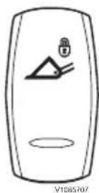
Separate attachment lock switch

Version 1A
Separate attachment lock switch
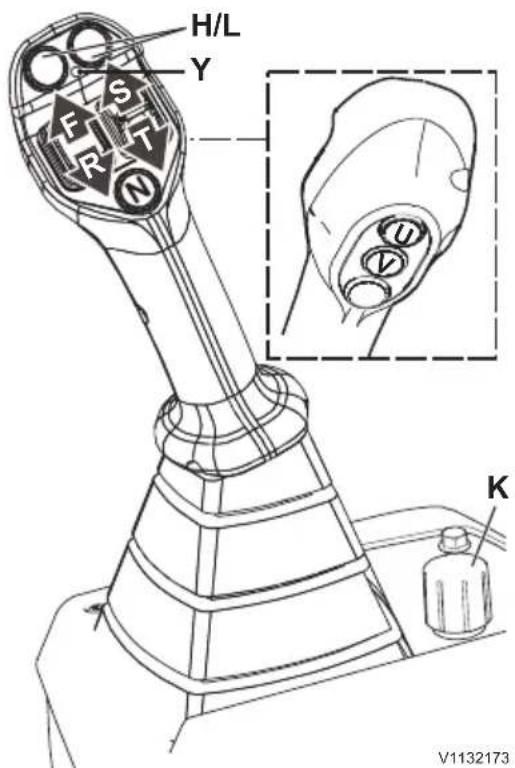
Version 1B
ground. If it is locked, the front wheels will begin to rise up.
NOTE!
Do not press the tines of the pallet forks against the ground to check for locking – the tines may bend. When connecting pallet forks, check visually for correct locking.
Disconnecting
1 The attachment should be in a level position just above the ground.
2 Press in the upper part of the separate attachment lock switch, and while the switch is pressed in, push control lever 2 (version 1A) or right roller control (S/T control on version 1B) forward in order to retract the lock pins. For version 1 A the roller has to be pulled in direction S and for version 1B the knob K has to be turned 1/4 turn from neutral position.
3 Lower the attachment until it has completely disengaged from the attachment bracket.
4 Reverse away from the attachment.
5 Delete the warning massage in the display by pressing the ESC button.

natural_image
Silhouette of a dog and a vehicle with a padlock, no text or symbols present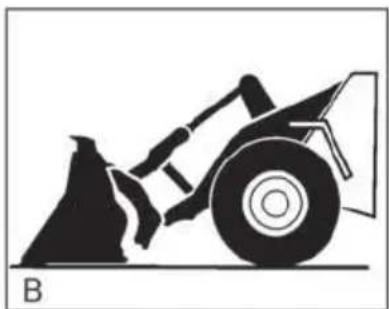
natural_image
Silhouette of a bulldozer pushing a vehicle (no text or symbols)
natural_image
Silhouette of a front-end loader with a lock and gear, labeled 'C' and 'L67276A' (no text or symbols on the diagram itself)A Attachment bracket's lock pins in unlocked position
B Tilt forward approx. 15° and hook the bracket into the upper attaching points on the attachment
C Lift, tilt-back until level and lock with the attachment bracket's lock pins

Figure showing all possible hydraulic options
A Electrical connector
B Attachment locking
C 3rd hydraulic function
D 4th hydraulic function (optional)
E High flow (optional)
Hydraulic function, 3rd and 4th

WARNING
Risk of crushing.
Sudden movement of attachments may cause serious injury or death to personnel near the machine.
Quick-acting controls operate the optional attachments. Operate the controls carefully.
NOTICE
When connecting or disconnecting hydraulic couplings, ensure that the couplings and the surrounding area are clean.
Make sure that the hydraulic oil in the attachment that is to be connected is not contaminated (foreign particles, water, etc.) and that it is of the same quality as that in the machine itself.
Connecting
1 See page 136. Follow the instructions for connecting.
2 Place the attachment level on the ground.
3 Depressurize the 3rd and 4th hydraulic function, see page 140.
4 Clean the hydraulic couplings thoroughly, both on the machine and the attachment.
5 Connect the attachment's hydraulic hoses to the machine.
6 Connect the attachment's electrical connector to the machine (if present)
NOTE!
Always check the operating control functions of the attachment before starting to work!
Disconnecting
1 Place the attachment level on the ground.
2 Depressurize the 3rd and 4th hydraulic function, see page 140.
3 Disconnect the attachment's electrical connector to the machine (if present)
4 Disconnect the attachment's hydraulic hoses from the machine.
5 After disconnecting the hoses: clean the hydraulic quick couplings from oil and protect all with caps.
6 Make sure that the attachment cannot fall over after disconnecting.
7 See page 136. Follow steps 2–4 to disconnect the attachment from the machine.
Pressure release
Residual pressure in the hoses makes it very difficult to disconnect or connect the quick-couplings.
This is facilitated, by releasing the pressure in the hydraulic system, when, for example, you want to disconnect a hydraulic hose:
1 Stop the engine.
2 Ignition switch in position 1.
3 Move the control for the relevant function back and forth several times, and hold it in its end-position for three seconds.
NOTE!
For pressure release of the 4th hydraulic function move the relevant levers - according to the control lever version. See page 139.
The pressure in hoses from timber grapples can be released in the following way:
1 Close the clamping arm fully.
2 Make a quick movement with the lever in the opposite direction.
The hoses become "slack" when the pressure is released.
NOTICE
The attachment should always rest on the ground when the pressure is released.
Excess pressure in a hydraulic attachment can be released by slackening the lock nut between the hose and the hydraulic pipe and then tightening it again. Meanwhile watch the attachment.
Collect the surplus oil.
Loading
For loading functions, see page 54.
■ For loading, blocking of the working hydraulics must be deactivated.
■ To pick up solid, cohesive materials it is recommended to quickly shift from tilt forward to tilt-back when penetrating the material. This eases bucket penetration into the material.
■ During transport of the excavated material, the bucket should not be higher than 0.5 m (20 in) above the ground.
■ Never operate over long distances with a loaded bucket raised up high.
■ With the loader lever in "float position", the bucket rests on the ground "without force" and can be used, e.g., to smooth out the tracks when reversing.
NOTE!
For road travel and maintenance work, the working hydraulics must be blocked to prevent unintended actuation.
- For information on bucket positioner (automatic tilt) and boom kick-out (automatic lift), see page 51.
- For information on Boom Suspension System, see page 32.
Buckets
When the machine is used with a bucket, the permitted working load is 50% of the tipping load for a fully steered machine. Depending on application and/or machine size, the manufacturer often recommends a utilization lower than 50%.
For information on weight, volume, load, edge savers, etc., contact your dealer to obtain the attachment catalogue.
Bucket teeth, changing, see page 206.

WARNING
Risk of fatal accidents.
Using attachments for lifting or transporting persons may lead to fatal accidents with serious crushing injury or death.
Never use attachments for lifting or transporting persons.
NOTE!
Excavating or surface stripping must not be performed at high speed if the bucket is tilted more than 15irc . A fully tilted bucket must be avoided.
Choosing bucket
■ The choice of bucket depends on the condition of the material (hard/loose), its density (heavy/light), and on the machine's tipping load.
A too large bucket, in relation to the material's density and the machine's tipping load, will give the impression that the machine is weak and unstable and will not increase productivity.
Working with buckets
To obtain efficient and safe operation it is important to keep the following points in mind:
■ Select the correct bucket.
■ Level the ground on the work site as much as possible and make sure that the ground is firm.
■ Avoid wheel spin by adapting the engine speed and by transferring as much weight as possible onto the front wheels. This is achieved by raising the bucket slightly after it has begun to enter the material.
■ Work with the machine straight against the material to obtain the greatest penetration. This also contributes to reduced tire wear.
Gravel and stockpile loading
1 Adjust the bucket so that it is level and lower it to the ground just in front of the gravel stockpile.
2 Penetrate the material. When the machine has almost come to a standstill due to the machine's maximum tractive effort being reached, begin to raise the bucket and tilt back at the same time with short lever movements.
If possible, avoid tilting the bucket forward when filling it. Exaggerated lever movements cause wheel spin. Never enter the material at high speed.
Suitable bucket: Straight bucket with or
without teeth

WARNING
Risk of crushing.
Falling load could cause serious injury.
Do not stand under a suspended load. Use appropriate loading and lifting equipment.
Excavating
■ When excavating and surface stripping, start by angling down the bucket 2–3°.
■ Operate in 1st gear and at low engine speed. Gradually increase engine speed and raise the bucket slightly at the same time.
■ If the ground conditions are poor and the wheels tend to spin, use the differential lock.
NOTE!
Never engage the differential lock when one of the wheels is spinning. Let up the accelerator pedal until the wheel stops.
Suitable bucket: Straight with or without teeth (alt. levelling bucket)
Suitable gear: 1st gear
BSS: Not activated

natural_image
Line drawing of a front-end loader dumping material into a dump truck (no text or symbols)Transporting load (load carrying)
■ The bucket should be tilted back all the way and held in the carry position 30–40 cm (12–16 in) above the ground.
NOTE!
If the Boom Suspension System is installed and activated, but does not engage, raise the lift arms slightly.
- Keep the haul road smooth and free from stones and other objects. There is always spill from a bucket that is too full.
■ Even out the road on the way back if necessary.
Suitable maximum
Approx. 15 km/h (9.3
speed: mph)
BSS: Activated
NOTE!
Remember that the stability of a heavily loaded machine changes when it is steered.
Dumping load
NOTE!
Operate very carefully if visibility is limited by the load or the attachment. Walk around the machine before starting and make sure that no persons remain in or enter the machine's work area. If you are uncertain, raise the load and check the conditions in the work area by looking under the load and operating at low speed. If necessary, arrange for a signalman to take charge and to help the operator in difficult circumstances. Work very carefully in order to prevent injuries and damage to property.
■ When working on a grade, try to arrange so that the load can be dumped uphill. This affects the machine's stability in a positive way.
- Keep the bucket as low as possible when dumping the load for easier positioning of the load and less impact from the load.
- When loading rock, try to fill the first bucket with as fine material as possible in order to reduce the impact of subsequent larger rocks.
Positioning of hauler
■ Positioning of the hauler (transport vehicle) is of great importance to making the loading operation efficient.
■ The operator should indicate where the hauler is to stand, suitably by "pointing" with the bucket. Having done so, the loader operator is responsible for that place being safe.
Levelling
■ The bucket should lie flat against the ground. To be able to fill any hollows you should have material in and in front of the bucket when operating forwards.
■ To finish off the levelling operation, keep the edge of the bucket slightly downward and reverse while pressing the bucket lightly against the ground.
Suitable bucket: Straight without teeth
(alt. levelling bucket)
BSS: Not activated
Multi-purpose bucket (optional equipment)
NOTE!
For connecting and disconnecting hydraulic hoses for 3rd hydraulic function, see page 139. Always check the attachment's operating control functions before starting to work.
A

B

C

natural_image
Mechanical linkage diagram showing a lever system with pivot point and dashed alignment line (no text or labels)D

A Loading
B Scraping
C Levelling
D Gripping
The multi-purpose (4-in-1) bucket is most suitable for all different types of earthmoving operations as well as for levelling, scraping, and gripping.
- The front grapple is operated with control lever 2 (version 1A) or right roller control (version 1B). See page 54 and onward.
NOTE!
When levelling in reverse gear, the front grapple on the bucket must only be partly open, so that any obstructions such as rocks or tree trunks do not damage or distort the front grapple. Travel speed must be matched to the condition of the road.
■ Material that is trapped between the lock cylinder and rear clam must be removed immediately, otherwise the cylinder's piston rod may be damaged or bent.
- Check the hydraulic lines at regular intervals for leaks and visible external damage, replace if needed.
■ Grease the bearings for the clamshell bucket and the lock cylinders every 50 operating hours. For quality of grease, see page 221.

natural_image
Line drawing of a mechanical device with internal compartments and mounting brackets (no text or symbols)■ Always release the pressure in the hydraulic system before starting maintenance or repair work.
■ Work in hydraulic systems must only be performed by authorized personnel.
High-tip bucket (optional equipment)
NOTE!
For connecting and disconnecting hydraulic hoses for 3rd hydraulic function, see page 139. Always check the attachment's operating control functions before starting to work.
The high-tip bucket is a combination of carrier and bucket. During tilting the carrier acts like an extension of the boom, thus providing high dump height. When loading and transporting, the bucket is tilted back between the carrier, and the bucket is in almost the same position as a standard bucket; thus there are barely any disadvantages with regards to breakout force, lifting force, and tipping load.
- The bucket cylinder is operated in the 'tilt function' with control lever 2 (version 1A) or right roller control (version 1B). See page 54 and onward.
- For loading, transporting, and lifting, tilt back the bucket all the way.
- Only empty the bucket when the desired lifting height has been reached.
NOTE!
Avoid tilting the high-tip bucket with the standard tipping function or, if necessary, tilt only at low tilt speed, so that the bucket remains tilted back all the way on the carrier.
- Avoid tilting the high-tip bucket forward or backward with full power against the end-stops to prevent damages to the bucket and cylinders.
■ Clean the carrier arms regularly from dirt deposits.
■ Check the hydraulic lines at regular intervals for leaks and visible external damage, replace if needed.
■ Check the rubber pads on the tilt-back stops at regular intervals, replace if needed.
■ Lubricate the bucket support and cylinder bearings every 50 operating hours. For quality of grease, see page 221.

natural_image
Technical line drawing of a mechanical component with no visible text or symbols■ Always release the pressure in the hydraulic system before starting maintenance or repair work.
■ Work in hydraulic systems must only be performed by authorized personnel.
Side-tip bucket (optional equipment)
NOTE!
For connecting and disconnecting hydraulic hoses for 3rd hydraulic function, see page 139. Always check the attachment's operating control functions before starting to work.
The side-tip bucket is suitable for all kinds of earthmoving operations such as backfilling trenches without a lot of turning.
- The bucket cylinder is operated in the "tilt function" with control lever 2 (version 1A) or right roller control (version 1B). See page 54 and onward.
- For loading, transporting, or lifting the load higher, the bucket must be tipped over until it is stopped by the support.
- When dumping (using side-tipping), all of the load should be dumped just before the maximum side tilt position is reached. If there is still some load left in the bucket, tilt it back carefully (not at full power) to prevent damage to the bucket and cylinder.
NOTE!
NOTE! Never try to empty the bucket by steering the machine! Steering may affect the stability of the machine. If load gets stuck in the bucket, lower the bucket and remove the load. Clean the bucket if necessary. Therefore, do not perform any unnecessary steering movements when the lift arms are up and the bucket cylinder is fully extended.
NOTE!
For longer transport and road travel, the bucket must generally be locked correctly and secured on the support.
■ Check the hydraulic lines at regular intervals for leaks and visible external damage, replace if needed.
■ Lubricate the bucket support and cylinder bearings every 50 operating hours. For quality of grease, see page 221.
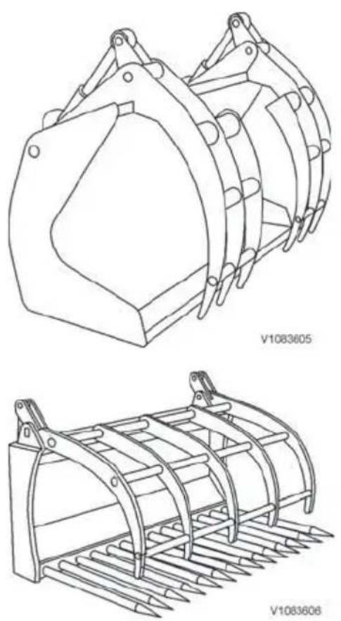
■ Always release the pressure in the hydraulic system before starting maintenance or repair work.
■ Work in hydraulic systems must only be performed by authorized personnel.
Scrap bucket (optional equipment)
NOTE!
For connecting and disconnecting hydraulic hoses for 3rd hydraulic function, see page 139. Always check the attachment's operating control functions before starting to work.
The scrap bucket is most suitable for loading of light metal scrap, e.g., aluminium scrap, tin plate, and similar bulky materials.
Universal fork with hydraulic grapple (optional equipment)
NOTE!
For connecting and disconnecting hydraulic hoses for 3rd hydraulic function, see page 139. Always check the attachment's operating control functions before starting to work.
The universal fork is most suitable for loading and transporting, e.g., biological waste, tree branches, hay, manure, and similar bulky materials.
- The grapples are operated with control lever 2 (version 1A) or right roller control (version 1B). See page 54 and onward.
- When entering the material keep the grapple fully open, otherwise the resulting very high pressure may cause leaks in hoses and seals.
- Do not operate the grapple with full power against the end-stop. The cylinders may be damaged due to high opening/closing speed.
■ Material that is trapped between the cylinder and bucket must be removed immediately, otherwise the cylinder's piston rod may be damaged or bent. - Check the hydraulic lines at regular intervals for leaks and visible external damage, replace if needed.
■ Grease the bearings on the grapple and cylinders every 50 operating hours. For quality of grease, see page 221.

natural_image
Technical line drawing of a mechanical bracket or frame structure (no text or symbols)■ Always release the pressure in the hydraulic system before starting maintenance or repair work.
■ Work in hydraulic systems must only be performed by authorized personnel.
Clamshell bucket (optional equipment)
NOTE!
For connecting and disconnecting hydraulic hoses for 3rd hydraulic function, see page 139. Always check the attachment's operating control functions before starting to work.
The clamshell bucket (also called mulch grapple bucket) is most suitable for loading bulky materials, e.g., biological waste, tree branches, bulky waste.
- The clamshell is operated with control lever 2 (version 1A) or right roller control (version 1B). See page 54 and onward.
- When entering the material keep the clamshell fully open, otherwise the resulting very high pressure may cause leaks in hoses and seals.
- Do not operate the clamshell with full power against the end-stop. The cylinders may be damaged due to high opening/closing speed.
NOTE!
■ Material that is trapped between the cylinder and bucket must be removed immediately, otherwise the cylinder's piston rod may be damaged or bent.
■ Check the hydraulic lines at regular intervals for leaks and visible external damage, replace if needed.
■ Grease the bearings on clamshell and cylinders every 50 operating hours. For quality of grease, see page 221.
■ Always release the pressure in the hydraulic system before starting maintenance or repair work.
■ Work in hydraulic systems must only be performed by authorized personnel.

Checking fork tines
A Angle
B Attaching lugs
C Thickness

natural_image
Technical line drawing of a mechanical clamp or bracket with labeled point D and reference number V1071131 (no text or symbols beyond labels)Fork frame
D Stop
Pallet forks
NOTICE
Only pallet forks approved for the machine by Volvo may be used.
Pallet forks may only be used for the intended application;
therefore they may not be used as pry bars to break out a stump, large rock, or similar.
They may not be overloaded or loaded obliquely.
They may not be used as lifting equipment together with chains or slings to lift objects.
Fork tine back frame and fork tines must be dimensioned to withstand loads which the lifting capacity of the machine permits.
Pallet forks and fork retainer must be kept free from dirt and rust and be well greased for best possible function.
NOTICE
With attached loading fork the machine must not be used in public traffic.
NOTICE
Make sure that the stops that prevent the fork arms from sliding off the fork frame are properly located. This is particularly important when the fork arms are moved sideways manually. Make sure that the fork arms are locked against the fork retainer, so that the fork arms are prevented from moving sideways.
■ Check the pallet forks regularly as regards wear. It is particularly important to check the heel of the fork tine.
■ Check that stops (D) for the fork arms are properly located.
- Check that the fork arms are locked against the fork frame.
■ The fork tine should not be used any more if:
- the fork tine has been worn down to 90% of its original thickness.
- the angle between fork tine's point and shank has become greater than 93°.
- the attaching eyes are worn or cracked.
■ Do not use welding to repair cracks or wear.
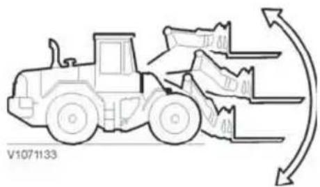
natural_image
Line drawing of a front-end loader with motion arrows indicating flow or movement (no text or symbols)
natural_image
Line drawing of a front-end loader with stacked boxes nearby (no text or symbols)Adjusting fork tines' position sideways
1 Place the fork tines just above ground level and tilt max. 150 forward.
2 Open the fork tines' lock and move the fork tines sideways to desired position.
3 Close the fork tines' lock so that the fork tines cannot move sideways.
Working with pallet forks
The most important points when working with pallet forks are:
■ The operator should have suitable training.
■ The operator is responsible for not exceeding max. values for the load.
■ The fork makes a semi-circular movement when lifting. Therefore, always start lifting some distance away from where the load is to be set down.
■ The fork may not be raised other than when stacking and unloading.
- Keep the fork tines low and angled up when operating without a load.
■ When stacking material the fork tines should be kept horizontal.
■ Select a suitable route with the smoothest ground surface or, when needed, level off the ground surface.
■ Adapt speed to the ground conditions.
■ For better stability when working with pallet forks it is important to maintain the right and recommended air pressure in the tires.
■ When handling a wide load it may be advantageous to move out the fork tines on the fork frame to increase stability of the load. Keep the center-of-gravity in mind and also make sure that the load is centered sideways.
It may be advantageous to reverse the machine when operating with a heavy load on a downhill grade.
NOTE!
For heavy-duty jobs requiring high breakout force, e.g., breaking out tree stumps and marble blocks – use attachments approved by Volvo.

natural_image
Line drawing of a front-end loader pulling stacked sacks (no text or symbols)
natural_image
Line drawing of a front-end loader with a box, showing motion direction (no text or symbols)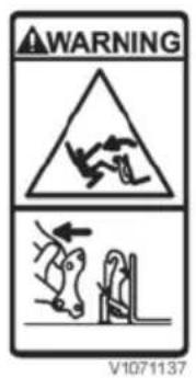
Picking up loads
■ Select suitable length of the fork tine so that it does not extend past the load. The pallet in front or material may be damaged since the fork tines have high penetration force.
■ Place the load as close as possible to the fork's vertical shank.
- Pick up the load with the smallest possible angle of the pallet fork.
■ Deviations from complete parallel movement may occur (see specifications) and this may affect use of the fork.
Operating with loads
- Keep the load low (30–40 cm) above the ground for best stability and visibility.
■ Tilt back to hold the load safer.
■ Reverse to the unloading site if the load reduces visibility.
■ Adapt speed to current operating conditions.
■ Use load supports when handling high loads.
Approval and legal requirements
Maximum permitted load according to CEN-standard EN 474-3 is stated in percent of the tipping load.
The percentages, which may not be exceeded, are as follows:
Uneven ground: 60% of tipping load
Solid and even ground: 80% of tipping load
It must be possible to control and handle the load hydraulically in all likely positions at the same time as all other hydraulic circuits are loaded. The max. permitted load is determined either by the machine's stability or its hydraulic force, whichever is lowest.
In countries outside the EU/EEA other rules may apply. Therefore, always check which local rules apply.

natural_image
Technical line drawing of a mechanical clamp or bracket assembly (no text or symbols)Timber grapples
(optional equipment)
NOTE!
For connecting and disconnecting hydraulic hoses for 3rd hydraulic function, see page 139. Always check the attachment's operating control functions before starting to work.
The log loader is a universal grapple. It is most suitable for loading and sorting logs.
- The hydraulic grapple is operated with control lever 2 (version 1A) or right roller control (version 1B), see page 54.
NOTE!
If the machine has been equipped with Boom Suspension System (BSS), this system must not be engaged when high accuracy is required for loading or unloading.
NOTE!
The logs are long – handle with care.
■ Check the hydraulic lines at regular intervals for leaks and visible external damage, replace if needed.
■ Grease the bearings on the grapple and cylinders every 50 operating hours. For quality of grease, see page 221.
■ Always release the pressure in the hydraulic system before starting any maintenance or repair work.
■ Work in hydraulic systems must only be performed by authorized personnel.

natural_image
Technical line drawing of two vehicle chassis components with labeled parts (no text or symbols beyond labels)Mount sprayer on (2). Connect the hydraulic and electric connectors, see also 135.
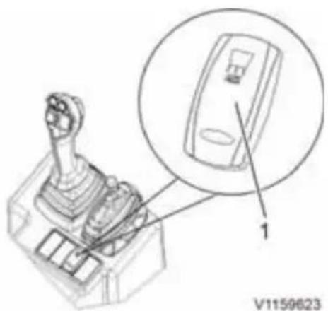
1=Pressing upper part of AUX switch = spreading function is preselected (and LED lights up)

Version 1A
Salt sprayer
NOTICE
The safety regulations and operating instructions issued by the manufacturer must be strictly observed.
Operating
The amount of salt is regulated by the engine speed. The optimum engine speed depends on the desired amount of salt and can be found in the manufacturer's instructions.
General information and instruction for salt sprayer can be found in the manufacturer's instructions.
By pressing the switch AUX (arrow) the spreading function is preselected (LED lights up). Switch: upper part pressed = spreading function preselected
1A Single lever with Aux lever
■ Moving the lever (S/T) to the back (in hold function) the sprayer is activated
■ Moving the lever (S/T) to the front (1-2 sec.) the shutter is activated (not part of the spreader neither the preparation)

Version 1B
1B Single lever with integrated Aux hydraulic functions (optional equipment)
■ Move the roller control knob (S/T) into the wanted position (spreader RPM) and hold, press the detent function button (U) and hold it there, release the roller control knob, release the detent button. The red LED lights up. The spreader is switched on.
■ Press hold button (U) to deactivate spreader.
NOTE!
To open the engine hood the spreader needs to be tilt back. Pull the bolt from the upper mount and tilt the empty spreader down to the bottom, full spreader needs to be tilt with a appropriate lifting tool.
NOTE!
When operating on a public road with full salting attachment, a front attachment which is heavy enough must be mounted so that the required load on the front axle is at least 20% of the total weight.

Version 1A

natural_image
Technical line drawing of a robotic arm with a close-up inset showing the head and jaw (no text or symbols)Special hydraulics
Hydraulic function, 4th switchable from 3rd
(optional equipment)
This equipment serves one hydraulic function at the time, 3rd or 4th. It is used when two auxiliary hydraulic functions are needed, for example road sweeper with hydraulic slewing device.
- Changing from 3rd to 4th hydraulic function = Pressing and holding the push button (arrow).
- Changing back from 4th to 3rd hydraulic = Releasing the push button (arrow).
Single control lever version 1B
NOTE!
Control lever version 1B provides flow adjustment, see page Controls. This is affecting also the 4th hydraulic function, when changing from 3rd to 4th.
This version provides common flow adjustment for hydraulic function 3rd or 4th, depending on what is selected. For further information see page 139.
Material handling arm
(optional equipment)

WARNING
Risk of fatal accidents.
Unauthorised persons within the work area around the machine could lead to serious crushing injury.
- Clear all unauthorised personnel from the working area.
- Keep a lookout in all directions.
- Do not touch control levers or switches during start.
- Sound the horn before beginning operation.

WARNING
Risk of fatal accidents.
Using attachments for lifting or transporting persons may lead to fatal accidents with serious crushing injury or death.
Never use attachments for lifting or transporting persons.
NOTE!
There is no end-stop beyond the maximum length of the inner arm, so there is a risk that the inner arm is pulled loose if the maximum load is exceeded.
The operator is responsible for the load being lifted not exceeding the maximum load limits for the machine and the forks.
NOTE!
Deactivate the Boom Suspension System (BSS) if equipped. High accuracy is required for loading or unloading.
1 Material handling arm, rigid
| Payload | |
| L30G 12 | 00 kg (2646 lb) |
| L35G 13 | 00 kg (2866 lb) |
2 Material handling arm, mechanically extendible
The load hook can be mechanically extended in 3 steps (of 200 mm / 79 in each) from a minimum
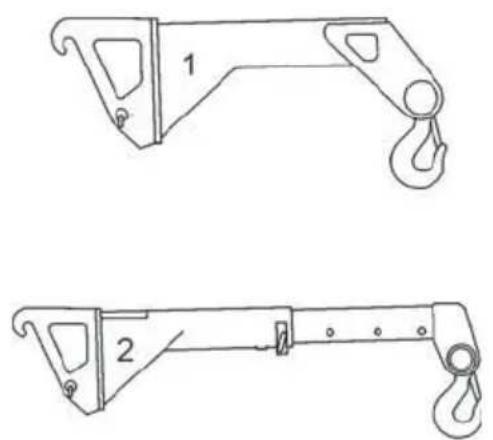
natural_image
Technical line drawings of two mechanical lifting devices, labeled 1 and 2, with hook and bracket details (no text or symbols beyond labels)length of 1060 mm / 417 in to a maximum length of 1660 mm / 654 in.
| Payload with: L | 30G L35G | |
| 1060 mm(417 in) | 1150 kg(2535 lb) | 1300 kg(2866 lb) |
| 1260 mm(496 in) | 1050 kg(2315 lb) | 1230 kg(2712 lb) |
| 1460 mm(575 in) | 950 kg(2094 lb) | 1150 kg(2535 lb) |
| 1660 mm(654 in) | 850 kg(1874 lb) | 1050 kg(2315 lb) |
V1083805
Road sweeping (optional equipment)
NOTE!
For connecting and disconnecting hydraulic hoses for 3rd hydraulic function, see page 139. Always check the control functions for the attachment before starting to work.
■ When using the machine on public roads check which local and national regulations concerning the attachment of road sweeping equipment must be complied with.
■ The road sweeping machine is most suitable for sweeping paved surfaces, but not for hazardous substances and health threatening dusts.
■ Connect the hydraulic hoses correctly so that the hoses are free and not squashed when starting the road sweeper.
■ For road sweeping machines with water spraying device plug the electric plug for the water pump into the socket on the right hand side on the lifting frame work.
■ During operation make sure that the height adjustable supporting wheels are adjusted to such a height, that the horizontally adjusted broom drum only just touches the ground. The weight of the road sweeping machine must always rest on the supporting wheels and not on the brushes. If the brushes are adjusted too low the broom bristles will brake and the steering rollers will vibrate.
■ All guards and safety devices must always be in place. During work the resting supports must be in raised position.
■ The working speed should be 4-8 km/h (2.5-5 mph) (select speed range gear stage "1" [turtle]).
■ Grease all lubrication points on the road sweeping machine after approx. 30 operating hours (for quality of grease, see page 221).
■ The condition of hydraulic oil lines must be examined at least once every year, replace if necessary.
Lifting objects
NOTICE
Use a safe lifting device with the proper rated capacity for the job.
The lifting devices that are used shall be adapted to and approved for the machine on which they are used.
NOTICE
Do not use damaged, broken or uncertified lifting devices.
NOTICE
Various countries have their own regulations concerning the use of the machine for lifting work, e.g. lifting freely suspended loads. For more detailed information you should contact your authorised Volvo dealer.
NOTICE
Observe the nominal loads that apply to the machine while transporting.
Stability
The stability of machines at work changes and is subject to great variations.
For work to be done safely, the operator must keep in mind and consider the special conditions at the time.
■ Standing the machine on a horizontal, stable and secure surface is one prerequisite for high stability.
- Watch out for soft, uneven, or sloping ground, as well as ground where there is risk of landslides. Be very careful with loading the machine sideways and in connection with other similar high-risk work. If the machine stands on sloping ground, the centre of gravity is displaced and the machine may end up in a position where it rolls over.
■ Make sure that the ground surface is stable and secure. Unstable ground, e.g. loose sand or wet earth can make work unsafe.

■ Do not turn suddenly with a suspended load. Remember the centrifugal force.
■ Operate the machine slowly and carefully.
■ Make sure that visibility is not reduced by big loads. If needed, get help from a signal man.
Slinging long loads
■ Boards, planks, reinforcing irons or similar should have the sling(s) arranged so that the load cannot fall out.
■ In general, girders should be lifted with a clamping device.
■ Padding made from, for example, split compressed air hoses may be used in order to protect the slings.
■ The slings should be well tightened.
Running checks of lifting attachments
Continuous supervision should be carried out at regular intervals by a knowledgeable and experienced person and arranged by the employer. Should wear, cracks or other deficiencies, which may jeopardise the safety of the machine or the lifting equipment, be noticed during the running checks, the machine or the lifting equipment must not be used.
Signalling diagram
If the operator's visibility is restricted, e.g., due to a big load, use a signal man.
The faster lifting, lowering, or movement that is required, the livelier the signal man's movements should be. If two or several operators use the same signal man, determine ahead of time how the lift is to be done and how signals shall be given to each operator.

natural_image
Simple line drawing of a person wearing a hard hat and jacket, arms extended outward (no text or symbols)START
Arms extended horizontally with palms facing forward

natural_image
Illustration of a person in a hard hat holding a hand with a circular arrow above their head (no text or symbols)RAISE
Right arm pointing up with palm facing forward and hand moving slowly in a circle

natural_image
Illustration of a person in hard hat and gloves holding hands with arrows indicating motion (no text or symbols)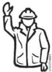
natural_image
Simple line drawing of a person wearing a hard hat and jacket, raising one hand (no text or symbols)STOP
Right arm pointing up with palm facing forward
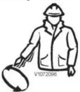
natural_image
Line drawing of a person wearing a hard hat and jacket, holding a circular object (no text or symbols)LOWER
Right arm pointing down with palm facing forward and hand moving slowly in a circle

natural_image
Illustration of a person in hard hat and gloves handling equipment with directional arrows (no text or symbols)
natural_image
Simple line drawing of a person wearing a hard hat and jacket, no text or symbols present.END
Hands held together at chest height

natural_image
Simple line drawing of a person in a hard hat and uniform, gesturing with one hand (no text or symbols)VERTICAL DISTANCE
Hands indicate relevant distance

natural_image
Line drawing of a person wearing a hard hat and jacket, raising both hands (no text or symbols)MOVE FORWARD
Both arms bent with palms facing up and underarms moving slowly and repeatedly up towards the body

natural_image
Illustration of a person in a jacket and hard hat pointing forward with bidirectional arrows (no text or symbols)OPERATE IN INDICATED DIRECTION
Arm extended horizontally with palm facing down and small movements back and forth slowly to the right
MOVE BACK
Both arms bent with palms facing down and underarms moving slowly and repeatedly down away from the body
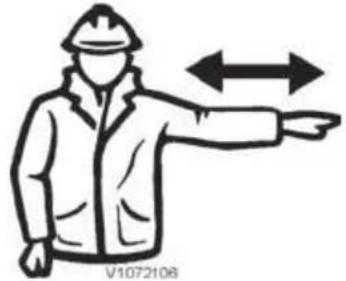
natural_image
Illustration of a worker in uniform pointing forward with double-headed arrows indicating bidirectional motion (no text or symbols)OPERATE IN INDICATED DIRECTION
Arm extended horizontally with palm facing down and small movements back and forth slowly to the left
DANGER (EMERGENCY STOP)
Both arms up with palms facing forward

natural_image
Simple line drawing of a person wearing a hard hat and jacket, hands on hips (no text or symbols)HORIZONTAL DISTANCE
Hands indicate relevant distance

Safety when servicing
This section deals with the safety rules that must be followed when checking and servicing the machine. Volvo will not accept any responsibility if other tools, lifting devices, or work methods described in this publication are used.
Other safety rules, information and warning texts are given in each section.
NOTE!
Lifting and supporting of the machine may only be performed by trained personnel.

Risk of burns!
Hot machine parts could cause burns.
Allow hot machine parts to cool before performing adjustments or service. Wear personal protective equipment.
Service position
Service position
BEFORE you begin any service work the machine must be placed on level ground and prepared as shown below.
AFTER service has been completed, any protective plates must be reinstalled and all engine covers are to be closed and locked.

| 1 | Lock the articulation joint. 6 Attach a black and yellow tag to the steering wheel. | |
| 2 | The attachment should be resting on the ground. | 7 Block the wheels in a safe way, e.g., with wheel blocks. |
| 3 | Apply the parking brake and turn off the engine, but leave the ignition key in position 1. | 8 Open the engine hood. |
| 4 | Release the hydraulic pressure. 9 Turn off the battery disconnector. | |
| 5 | Remove the ignition key. 10 Let the engine cool. | |
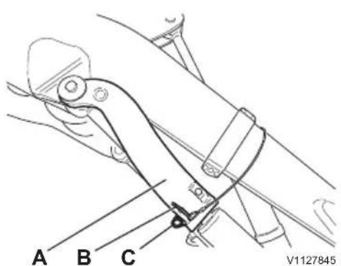
Safety brace in support position
A Safety brace
B Lock pin
C Cotter pin

Safety brace in support position
A Safety brace
B Lock pin
C Cotter pin
Safety brace (optional equipment)
NOTE!
The safety brace should only be used if a support such as in the service position with raised loader arms (see above) is not available.

Risk of crushing.
If the raised loader arms drop crushing injuries could occur.
Safely support the loader arms, before persons start working below the loader arms.
Setting the safety brace in support position
1 Empty the bucket (or the attachment) and tilt it fully forward.
2 Raise the loaders arms to the highest position.
NOTE!
Check that the bucket (or the attachment) is completely empty and make sure that there are no persons in a position below the raised loader arm.
3 Remove the cotter pin (C) and pull out the lock pin (B) from the storage position. At the same time, take the load off the brace (A) and hold firm. During this operation do not walk under the lift arm system to take the lift cylinder blocking device out of its storage position.
4 Fold down the safety brace (A) to its support position (against the piston rod) and secure it with lock pin (B) and cotter pin (C).
5 Carefully lower the loader arms until they rest against the safety brace.
NOTE!
If the safety brace, or any parts associated with this equipment, should be damaged, the damaged parts must be taken out of use and replaced immediately.
Contact a workshop authorized by Volvo.

Safety brace in storage position
A Safety brace
B Lock pin
C Cotter pin
Setting the safety brace in storage position
1 Start the engine.
2 Raise the loader arms to the highest position.
3 Remove the cotter pin (A) and pull out the lock pin (B).
4 Fold up the safety brace (A) and secure it in storage position with the lock pin (B) and the cotter pin (C).


natural_image
Line drawing of a hand holding a helmet and wrist (no text or symbols)Before service, read
Prevent personal injuries
- Read the Operator's Manual before the service work is started. It is also important to read and follow information and instructions on plates and decals.
■ Do not wear loose-fitting clothing or jewellery, which can get caught and cause injury.
■ Always use a hard hat, safety glasses, gloves, and protective footwear when required by the job.
■ Make sure that the ventilation is sufficient when starting the engine indoors.
■ Do not stand in front of or behind the machine when the engine is running.
■ Turn off the engine before removing any protective covers or opening the engine hood.
■ When the engine is stopped, there is a remaining accumulated pressure in the pressurised systems. If a system is opened without having first released the pressure, liquid under high pressure will jet out.
■ Use a piece of paper or cardboard to check for leaks, never use your hand.
■ Make sure that steps, handles, and slip-protected surfaces are free from oil, diesel fuel, dirt, and ice.
■ Only step on parts of the machine provided with slip-protection.
■ It is important to use correct tools and equipment. Broken tools or equipment should be repaired or changed.
If service work has to be done under a raised attachment, first secure the attachment. Engage the control lever lock-out (safety bar), if installed, and apply the parking brake.
Prevent machine damage
■ When lifting or supporting the machine or parts of the machine, use equipment with a sufficient lifting capacity.
■ Lifting devices, tools, working methods, lubricants and parts prescribed in the Operator's Manual should be used. Volvo CE will not accept any responsibility otherwise.
■ Make sure that no tools or other objects, which may cause damage, have been forgotten in or on the machine.
■ Release the pressure in the hydraulic system before starting the service work.
■ Never set a relief valve to a higher pressure than that recommended by the manufacturer.
■ Machines, which are used within a polluted or in another way insanitary area should be equipped for this kind of work. Special safety regulations apply when servicing such a machine.
■ When installing two-way radio, mobile telephone, or similar equipment, the installation should be performed according to the manufacturer's instructions in order to eliminate interference with the electronic system and components intended for the machine's function, see page 21.
■ Actions to be taken in connection with electric welding, see page 196.
■ Make sure that all protective plates, covers, and hoods on the machine are in place before the engine is started and the machine is used.
■ Use the 'three-point stance' (two feet and one hand) when cleaning or scraping the front windshield.
Prevent environmental impact
Keep the environment in mind during service and maintenance. Environmentally hazardous oils and fluids, released into the environment, cause damage to the environment. Oil is broken down very slowly in water and sediment. One litre of oil is enough to contaminate millions of litres of drinking water.
NOTE!
Common for the following points is that all waste must be brought to a waste management company approved by the authorities.
■ When draining, oils and liquids must be collected in suitable containers and steps taken to avoid spills.
■ Used filters should be drained of all fluid before being deposited as waste. Used filters from machines operating in conditions with asbestos or other health-hazardous dust should be placed in the tight-sealing bag that accompanies the new filter.
■ Batteries contain substances hazardous to personal health and the environment. Used batteries must be handled as environmentally hazardous waste.
■ Consumables, e.g., used rags, gloves, bottles, and cans may also be contaminated by
environmentally hazardous oils and fluids. These must also be handled as environmentally hazardous waste.
Fire prevention

WARNING
Risk of fire.
Operating in environments with flammable or other explosive particulates in the air could increase the risk of fire.
Use special equipment and proper ventilation when operating in hazardous environments.
There is always a risk of fire. Find out what kind of fire extinguisher is used on your working site and how to use it. If the machine is equipped with a fire extinguisher, it should be kept inside the cab on the left side of the operator.
If the machine is to be provided with a hand-held fire extinguisher, it should be of the ABE type (ABC in North America). The designation ABE means that it is possible to extinguish fires in both solid organic material and liquids, and that the fire extinguishing compound does not conduct electricity. Efficiency class I means that the effective operating time of the extinguisher must not be less than 8 seconds, class II at least 11 seconds and grade III at least 15 seconds.
A hand-held fire extinguisher ABE I normally corresponds to a powder content of 4 kg (8.8 lb) (EN-grade 13A89BC), standard EN 3-1995, parts 1, 2, 4 and 5.
Fire prevention measures
■ Smoking or open flames are forbidden near a machine when refuelling or when the fuel system is open and in contact with the surrounding air.
■ Diesel fuel oil is flammable and must not be used for cleaning. Use conventional car care products meant for cleaning or degreasing. Also bear in mind that certain solvents can cause skin rashes, damage to the paint finish and constitute fire hazard.
- Keep the place clean where service work is to be done. Oil and water can make the floor and steps slippery, and is also dangerous in connection with electrical equipment or electrically powered tools. Oily and greasy clothes are a serious fire hazard.
■ Check daily that the machine and the equipment are free from dust and oil. This reduces the risk
of fire and it is also easier to detect defective or loose parts.
NOTE!
Be careful when using a high-pressure washer for cleaning. Electrical components and the insulation on wiring can be damaged even at relatively low pressure and temperature. Protect electrical components and wiring in an appropriate manner.
■ Be extra thorough when cleaning a machine that is operated in a conditions with high risk of fire, e.g., saw mills and landfill sites. The risk of spontaneous combustion can be reduced further by installing insulation on the muffler.
■ It is important that the fire extinguisher is maintained in order to work when it is needed.
- Check that fuel lines, hydraulic hoses, brake hoses, and electrical wiring do not have any chafing damage or risk being exposed to chafing due to incorrect installation or clamping. This applies especially to unfused cables, which are red, are marked R (B+), and are routed:
- between the batteries
- between battery and starter motor
- between alternator and starter motor
Electrical cables must not have direct contact with oil or fuel lines.
- Do not weld or grind on components which are filled with flammable liquids, e.g. tanks and hydraulic pipes. Exercise care with such work also in the proximity of such places. A fire extinguisher should be kept near to hand.
Actions in case of fire
If the circumstances permit and your own safety is not jeopardised, take the following steps at the slightest sign of fire:
1 Stop the machine, if it is moving.
2 Lower the attachments to the ground.
3 Move the lock-out lever, if installed, to locked position.
4 Turn the start key to the stop position.
5 Exit the cab.
6 Call the fire department.
7 Turn off the battery disconnector, if it can be reached safely.
8 Try to put out the fire, if possible. Otherwise move away from the machine and the danger area.
Actions after a fire
The following safety precautions must be taken when handling a machine that has been exposed to fire or other intense heat:
■ Use safety goggles and thick rubber gloves.
■ Never touch burnt components with your bare hands to avoid contact with melted polymers. First wash thoroughly with lime water (a solution of calcium hydroxide, that is, slaked lime in water).
■ Handling heated fluor rubber, see page 174.
Handling hazardous materials
Heated paint

WARNING
Risk of toxin inhalation.
Burning of painted, plastic or rubber parts produces gases that could damage respiratory tracts.
Never burn painted or rubber parts or any plastics.
When heated, paint gives off poisonous gases.
Therefore, the paint must be removed from an area of at least 10 cm from the spot where welding, grinding, or cutting with a torch is to be carried out. In addition to the health hazard, the weld will be of inferior quality and strength, which in the future may cause the weld to break.
Methods and precautionary measures when removing paint
■ Blasting
- use respirator and protective goggles
■ Paint remover or other chemicals
- use a portable air extractor, respirator and protective gloves
■ Grinding machine
- use a portable air extractor, respirator and protective gloves and protective goggles
Painted parts that have been discarded must never be burnt. They must be taken care of by an approved refuse handling plant.
Rubber and plastics which have been heated
Polymer materials can, when heated, form compounds which are dangerous to health and environment and must therefore never be burned when scrapped.
If gas cutting or welding is to be carried out near such materials, the following safety instructions must be followed:
- Protect the material from heat.
- Use protective gloves, protective goggles and an approved respirator.
Fluoro-carbon rubber which has been heated

WARNING
Risk of toxin inhalation.
Fluoro rubber seals when heated beyond their rated limits will release a very toxic gas that is corrosive to respiratory tracts.
Move away from and do not inhale any smoke coming from the machine. Inhalation of toxic gas requires immediate medical attention.
When handling a machine which has been damaged by fire or been exposed to other intense heat, the following protective steps must under all circumstances be taken:
■ Use thick, gloves made of rubber and wear protective goggles.
■ Discard gloves, rags etc. that been in contact with heated fluoro-carbon rubber after having first washed them in lime water (a solution by calcium hydroxide, i.e. slaked lime in water)
■ The area around a part that has been very hot and which may be made of fluoro-carbon rubber must be decontaminated through thorough and ample washing with lime water.
As a precautionary measure all seals (O-rings and other oil seals) must be handled as if they were made from fluoro-carbon rubber.
■ The hydrofluoric acid may remain on the machine parts for several years after a fire.
If swelling, redness or a burning sensation occurs and one suspects that the cause may be contact with heated fluoro-carbon rubber contact a medical doctor immediately. Symptoms may not appear until after several hours without any previous warning.
■ The acid cannot be rinsed or washed away from the skin. In stead treat with Hydrofluoric Acid Burn Jelly or similar before contacting a doctor.
Refrigerant
NOTE!
All types of service on the air conditioning unit must be done at accredited workshops by, or under the supervision of, a person in a supervisory position with certified competence.

WARNING
Risk of frostbite.
The refrigerant media is moderately hazardous to the health. In liquid form the refrigerant could cause frostbite. When in the form of a gas at high concentration it has an anaesthetic effect and at lower concentration it primarily affects the nervous system.
Use personal protective equipment.
The air-conditioning unit of the machine is filled with refrigerant R134a at the factory. R134a has no damaging effect on the ozone layer of the atmosphere, however, it contributes to the greenhouse effect and must therefore never purposely be released into the open air.
NOTICE
R134a must never be mixed with another kind of refrigerant, e.g. R12, as this leads to a breakdown of the unit.
In case of contact with escaping refrigerant, the following actions must be taken:
■ The gases, which are formed when refrigerant is heated may have seriously harmful effects on lungs and the nervous system even at low concentrations and when no smell is detectable. High concentrations have a narcotic effect. An exposed person must be moved out of the danger area out into the open air. Seek medical advice if there are remaining symptoms.
In liquid form, the refrigerant may cause frost-bite. Carefully heat the injured area with lukewarm water or warm clothes. Seek medical advice, if there are remaining symptoms.
- Seek medical advice, if liquid refrigerant has come into contact with someone's eyes.
If a leak is suspected, leave the dangerous area and contact an accredited workshop to obtain information about what action should be taken.
Batteries

WARNING
Risk of chemical burns.
Contact with battery acid causes serious chemical burns.
Always wear personal protective gloves, goggles and clothing when handling batteries.
■ Do not smoke near batteries, as these give off explosive gases.
■ Make sure that metal objects, e.g. tools, rings and watch straps, do not come into contact with the battery pole studs.
■ Make sure that the battery terminals' caps always are installed.
■ Do not tilt a battery in any direction. Battery electrolyte may leak out.
■ Do not connect a discharged battery in series with a fully charged battery. Risk of explosion.
■ When removing a battery, disconnect the ground cable first and when installing, connect the ground cable last to reduce the risk of sparks.
■ Discarded batteries must be taken care of according to current national regulations.
Charging batteries, see page 196.
Starting with booster batteries, see page 93.
Dust of crystalline silicon dioxide (silica dust)

WARNING
Risk of hazardous inhalation.
Working in environments containing dangerous dust can lead to serious health problems.
Wear personal protective equipment when working in dusty environments.
Crystalline silicon dioxide is a basic component part of sand and granite. Many activities on building sites and in mines, such as ditching, sawing and drilling, generate dust that contains crystalline silicon dioxide. This dust may cause silicosis (miner's consumption).
The employer or the work site management should inform the operator about the presence of any crystalline silicon dioxide on the work site and
provide special work instructions and actions, as well as necessary protective equipment.
Also check local and national regulations on crystalline silicon dioxide and silicosis.
Handling line, tubes and hoses

WARNING
Risk of high pressure injection.
Oil or fuel leaks from high pressure hoses could cause serious injury caused by high pressure injection.
If oil or fuel leaks from high pressure hoses or loose screws is found, stop operations immediately and contact an authorized Volvo dealer workshop.
■ Do not bend high pressure lines.
■ Do not strike high pressure lines.
■ Do not install any lines that are bent or damaged.
■ Check lines, tubes and hoses carefully. (leakage, damage, deformity and aging)
■ Do not reuse hose, tube and fittings.
■ Do not use your bare hand to check for leaks.
■ Tighten all connections. Consult your Volvo Construction Equipment dealer for the recommended tightening torque.
If any of the following conditions are found, replace the parts. Consult your Volvo Construction Equipment dealer.
■ Connections and end fittings are damaged, leaking, deformed or aged.
■ Outer coverings are chafed or cut.
■ Strengthening wires are exposed.
■ Outer coverings are ballooning.
■ Flexible part of the hoses are kinked.
■ End fittings are displaced.
■ Foreign material is embedded in the coverings.
NOTICE
Make sure that all clamps, guards and heat shields are correctly installed. This contributes to preventing vibrations, chafing against other parts and excessively strong generation of heat.

natural_image
Line drawing of a worker in uniform carrying a toolbox and holding a tool (no text or symbols)Service and maintenance
This section describes the maintenance and service actions that the machine operator can perform. These are summarized in the section "Lubrication and service chart" as an illustration with associated table for each interval, see page 213.
Other actions require trained workshop personnel or special equipment. For this type of job, we recommend that you contact an authorized Volvo workshop.
Exhaust control systems (USA)
The exhaust control systems for your new Volvo Construction Equipment engine have been designed, manufactured, and tested using genuine parts, and they have been certified according to American federal and California regulations on exhaust control. According to these all spare parts that are to be used for maintenance, repairs, or replacement of exhaust control systems shall be parts from Volvo Construction Equipment. The owner may let any workshop or mechanic perform maintenance, replacement, or repair of exhaust control components and systems that have been certified by the US Environmental Protection Agency. The owner may choose to use other parts than genuine Volvo Construction Equipment parts for such maintenance, replacement, or repair without the warranty becoming invalid, but the warranty does not cover the cost of such services or parts.
Service history
After each completed service at a workshop authorized by Volvo, the service journal shall be filled in, see page 254. The service journal is a valuable document, which can be referred to when, e.g., selling the machine.
Arrival Inspection
Before the machine leaves the factory, it is tested and adjusted. The dealer or distributor must also carry out arrival inspections according to the applicable form.
Delivery Inspection
Before the machine leaves the factory, it is tested and adjusted. The dealer or distributor must also carry out delivery inspections according to the applicable form.
Delivery Instructions
When handing the machine over, the dealer must give the buyer delivery instructions according to the applicable form, which must be signed, if the warranty is to apply.
Service Programme
For any factory warranty to be valid, the machine shall be maintained according to the service program established by Volvo. The service program is continuous with fixed intervals. The operating time between intervals only applies if the machine is used in normal environment and operating conditions. Ask your Volvo dealer what is right for your specific machine.
Cleaning machine
The machine should be cleaned regularly with conventional car care products in order to eliminate the risk of damage to the paint finish and other surfaces on the machine.
NOTICE
Avoid using strong cleaning agents or chemicals in order to minimise the risk of damage to the paint finish.
NOTE!
Daily clean the areas on the machine where dust, chips, and similar may collect in order to minimize the risk of fire, see page 183.
Recommendations for cleaning the machine:
■ Place the machine in a place intended for cleaning.
■ Follow the instructions supplied with the car care product.
■ The water temperature must not exceed 60\ °C ( 140\ °F ).
If high-pressure washer is used, keep a distance of at least 20–30 cm (8–12 in) between the nozzle and the machine. Too high pressure and too short distance may cause damage. Protect electrical wiring in an appropriate way.
NOTICE
If you are using a high-pressure wash, take care so that the decals do not loosen.
■ Use a soft sponge.
■ Finish by rinsing the whole machine with only water.
■ Always lubricate the machine after washing.
■ Touch-up the paint finish when required.
If a decal is tattered or illegible it must be replaced immediately, see page 25 for more information.
Paint finish maintenance
Machines used in corrosive conditions are more prone to rusting than others. As a preventive measure it is recommended that the paint finish should be maintained every sixth months. If there is any doubt whether the conditions are corrosive or not, contact your dealer.
■ At first clean the machine.
■ Apply Dinol 77B (or corresponding transparent waxy anti-rust agent) at a thickness of 70–80 μ.
■ A protective layer of underseal Dinol 447 (or corresponding) may be applied under the mudguards where mechanical wear is expected.
Touch-up painting
■ At first clean the machine.
■ Check if any areas of the paint finish are damaged.
■ Rectify any damage to paint finish in a professional way.


Areas that need to be checked and cleaned:
1 Top of the hydraulic tank
2 Air intake, engine
3 Under the engine hood, accumulated debris on the engine's valve cover and other surfaces, especially on hot surfaces such as the DPF and burner (with D3.3H-engine) / DOC (with D3.3M-engine), turbocharger, exhaust pipe, exhaust manifold, preheating coil, and alternator. See figure below of the engine compartment. Also check and clean by the starter motor, oil filler point, oil filters, and fuel filter
4 Inside cooling fins and casing
5 Fuel filler point and top of the fuel tank with surrounding areas
Cleaning engine compartment
Machines operating in dusty, fire-hazardous environments, e.g., log handling, woodchip handling, grain handling, and animal feed industries, require daily inspection and cleaning of the engine compartment and surrounding areas.
When operating in other conditions, checking and cleaning is required at least once a week.

WARNING
Risk of burns.
Engine and exhaust system components get very hot and can cause severe burns.
Avoid contact with engine compartment covers, engine components and exhaust system until the engine is cooled down.
■ Preferably, the machine should be cleaned at the end of the work shift before it is parked.
■ Use personal protective equipment such as protective goggles, gloves, and protective breathing equipment.
■ Start with the highest areas on the machine and finish with the lowest on top of the fuel tank and areas near the fuel tank.
■ Loose material is removed mechanically, and only in special cases using compressed air. If compressed air is used, wear suitable breathing protection.
■ After cleaning, check and repair any leaks. Close all covers and hoods.

natural_image
Technical line drawing of a mechanical assembly with numbered components (no readable text or symbols)Hot surfaces in the engine compartment (D3.3M-engine)
1 Diesel oxidation catalyst
2 Turbo
3 Hot air from turbo
4 EGR cooler

Hot surfaces in the engine compartment (D3.3H-engine)
1 Diesel particulate filter
2 Turbo
3 EGR cooler
Service points

| 1 | Engine oil filling point 9 Battery (behind the counterweight) | |
| 2 | Engine oil dipstick 10 Battery disconnector | |
| 3 | Fuel filling point 11 Hydraulic oil level glass | |
| 4 | Water trap (on primary fuel filter) 12 Hydraulic oil filling point | |
| 5 | Engine air cleaner 13 Windshield washer fluid reservoir | |
| 6 | Coolant filling point (expansion tank cap) | 14 Brake fluid tank |
| 7 | Raw air intake (rain cap) 15 Radiator | |
| 8 | Cab ventilation filters (behind the cover on the left side of the machine) | 16 Condenser for the air conditioning |

Engine oil dipstick
A Engine oil dipstick
B Engine oil filling point
Engine
Engine oil level, checking
Check engine oil level every 10 hours.
The oil level should be checked before starting the engine.
1 Park the machine on level ground. Apply the parking brake.
2 Turn off the engine.

WARNING
Risk of entanglement!
Rotating parts could lead to entanglement.
Keep a sufficient distance from rotating parts.
3 Open the engine hood.
NOTE!
The level check should be carried out when the oil has had time to run down to the bottom of the sump.
4 Pull out the dipstick and wipe it clean with a lint-free rag, insert it until it bottoms out, and pull it out again.
The dipstick should be covered with oil up to the top marking (MAX).
NOTE!
Always make sure that the oil level is close to the MAX-marking when the machine is operated on grades or slopes.
If the oil level is near or below the bottom marking (MIN), top up the oil immediately to avoid severe engine damage.
Engine oil, topping up
NOTE!
It is important to use recommended oil grades (quality), otherwise clogging of the diesel particulate filter increases.
1 Top up through the filling point (B) if the oil level is low.
2 Check the oil level regularly.
For quality of oil, see page 218.

Fuel filling point
A Fuel filling point (under the engine hood)
Fuel system
Fuel, filling
For fuel quality, see page 222
The fuel tank should be topped up at the end of each work day. This prevents the formation of condensation water, as much as possible.
- Thoroughly clean the area around the tank cap.
- Only fill with clean fuel! Clean fuel is essential for trouble-free operation of the diesel engine.
Fuel tank capacity, approximately 84 litres (22 US gal)

WARNING
Risk of fire.
Burning fuel can cause fatal injuries.
Stop the engine before filling fuel.

WARNING
Risk for fire.
Regeneration generates hot exhaust and causes hot exhaust pipe. Do not perform regeneration in a flammable environment.

WARNING
Risk of explosion!
Flammable liquids could explode.
Smoking, open flame and fire are prohibited.
A reduction in engine power can be caused by a clogged fuel filter. If a fuel filter clogs too quickly, check the fuel for contamination. Clean the tank, make sure it is closed correctly.
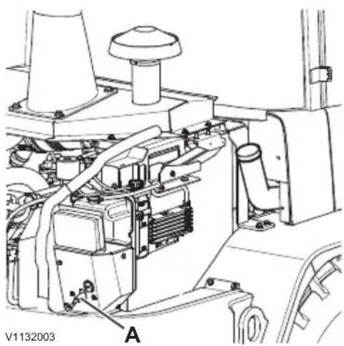
natural_image
Technical line drawing of a mechanical assembly with labeled component A (no readable text or symbols)A Battery disconnector
Fuel system, air bleeding
Bleeding of the fuel system may be necessary if:
- Service work has been done on the fuel system.
- The engine has been run dry of fuel.
NOTE!
Air bleeding may not be performed using the starter motor.
NOTE!
First, make sure that there is sufficient fuel in the fuel tank and that the battery disconnector is turned On.
1 Turn the ignition key to position 1.
2 Wait 30 seconds and let the electric fuel pump prime the system.
3 Start the engine and let it run for one minute.
NOTE!
If the engine does not start, repeat bleeding procedure for 30 seconds.
4 Turn off the engine.
5 Turn off the battery disconnector.
6 Check the fuel filters and connected hoses for leaks.
NOTE!
Manual air bleeding cannot be performed (there is no hand pump).
Take care of filters, oils and liquids in an environmentally safe way. See page 168.

1 Water trap
2 Drain valve
3 Drain hose
Water separator, draining
Drain the water trap when necessary. Check daily and according to signal.
Place the machine in the service position; see page 165.
1 Turn off the engine.
2 Check if there is water in the water trap (A). Drain the water if necessary by taking the following actions.
3 Place the drain hose (B) outside of the engine compartment.
4 Place a suitable container under the drain hose to collect draining fuel.
5 Open the drain valve (C) until all water has been forced out of the water trap. When fuel instead of water starts to flow, close the drain valve.
6 Place the drain hose inside the engine compartment.
Handle filters/oils/liquids in an environmentally safe way, see page 168.
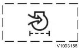
Display message "engine air filter clogged"

natural_image
Technical line drawing of a mechanical assembly with no visible text or symbolsEngine air cleaner
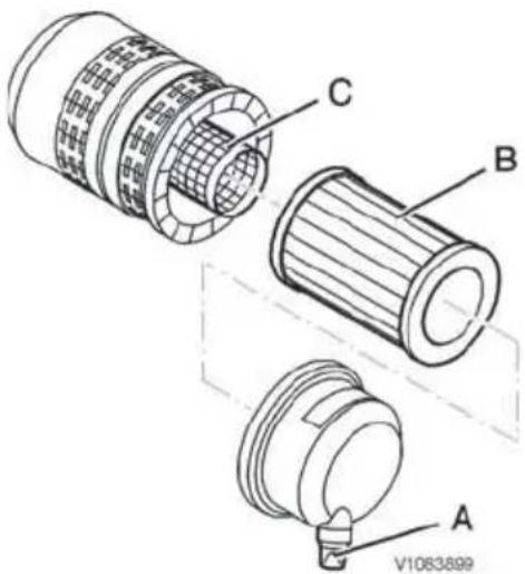
Engine air cleaner components
A Dust discharge valve
B Primary air filter
C Secondary air filter
Engine air cleaner
Squeeze the dust discharge valve regularly to clean the inside of the engine air cleaner.
The rate of engine wear depends mainly on the cleanliness of the induction air. The air cleaner prevents dust and other impurities from entering the engine.
NOTE!
Check immediately if the engine air cleaner needs to be cleaned if the message "engine air filter clogged" is shown on the display unit.
NOTE!
Risk of machine damage! Never run the engine without a filter or with a damaged filter.
1 Turn off the engine.
2 Squeeze the dust discharge valve (A) several times to remove the collected dust from the inside of the air cleaner cover.
3 Release the three retaining clips and remove the air cleaner cover. Make sure that the dust valve is not damaged or clogged.
4 Wipe away all dirt from around the air cleaner housing and cover.
5 Remove the primary air filter (B).
NOTE!
Do not remove the secondary air filter - it should not be cleaned. If it needs to be replaced, contact a workshop authorized by Volvo.
6 To clean the primary air filter, remove dust and debris by shaking it or by blowing with low-pressure compressed air from the inside and out of the filter.
NOTE!
Do not attempt to clean the primary filter element by striking it.
NOTE!
Replace the primary air filter if it has been cleaned five times, or if it cannot be cleaned. In this case the secondary air filter needs to be replaced as well.
Contact a workshop authorized by Volvo.

Cooling system
For the cooling system to function without problems, the coolant level should be checked regularly and the radiator be blown clean.
Coolant
The cooling system is filled with Volvo Coolant VCS, which meets the highest requirements for anti-freeze, anti-corrosion, and anti-cavitation properties. In order to avoid damage to the engine, is it very important that Volvo Coolant VCS is used when topping up or when changing coolant.
Volvo Coolant VCS is yellow and a sticker at the filling point shows that the system is filled with this coolant (see figure).
NOTICE
Volvo Coolant VCS must never be mixed with any other coolant or corrosion protection to avoid damage to the engine.
If concentrated Volvo Coolant VCS and clean water (see page 220) is used, the table below shows the approximate amount of concentrated coolant needed for protection against freezing. The content of Volvo Coolant VCS may never be less than 40 % of the total mixture.
If there is any doubt about the quality of the water, use ready-mixed Volvo Coolant VCS, which contains 40% concentrated coolant.
NOTICE
If the ready-mixed Volvo Coolant VCS is used, it must not be mixed with any other ready-mixed coolants, as this may cause damage to the engine.
| Freezing protection down to | Content of concentrated coolant |
| -25 °C (-13 °F) 40% (mixture from factory) | |
| -35 °C (-31 °F) 50% | |
| -46 °C (-51 °F) 60% |
Handle filters, oils, and liquids in an environmentally safe manner, see page 168.
Coolant level, checking
Check the coolant level daily.
1 Turn off the engine and apply the parking brake.
2 Open the engine hood and turn off the electrical power with the battery disconnector.

WARNING
Risk of entanglement.
Rotating parts can cause injury.
The engine must be off and the battery disconnector switch off.
3 Let the cooling system cool down.
4 Check that the coolant level is between the markings MIN and MAX on the expansion tank.
Topping up coolant
If the alarm text for low coolant level is shown, the coolant must be topped up.
NOTICE
Volvo Coolant VCS must never be mixed with any other coolant or corrosion protection to avoid damage to the engine.
1 Slowly loosen the expansion tank cap (A).

WARNING
Risk of scalding and severe burns to unprotected skin.
High-pressurised hot coolant may rush out of expansion tank and cause severe burns. Before removing the expansion tank pressure cap:
■ Shut down the engine.
■ Allow the engine to cool
■ Turn the pressure cap slowly to release any pressure.
2 Top up with coolant until the coolant level is between the markings MIN and MAX on the expansion tank.
3 Reinstall the expansion tank cap (A) tightly and check the system for leaks.

natural_image
Technical line drawing of a mechanical assembly with labeled component A (no readable text or symbols)Expansion tank
A Expansion tank cap


natural_image
Technical line drawing of an internal combustion engine assembly (no text or labels)Cleaning the radiator
Radiator, cleaning
The radiator should be cleaned at regular intervals in order to safeguard engine cooling. When operating under especially dusty conditions, the radiator should be checked daily.
NOTICE
Cleaning the radiator should always be carried out with the engine turned off.
NOTE!
High-pressure water jet should not be used – the radiator cores can be damaged easily.
WARNING
Risk of crushing and cutting.
Rotating parts could cause serious injury.
Shut down the engine before cleaning the machine or any component of the machine.
1 Turn off the engine.
2 Open the engine hood and turn off the electrical power with the battery disconnector.
3 Blow the radiator clean with compressed air from the inside out (see arrow).

natural_image
Technical diagram of a mechanical assembly with labeled component A (no readable text or symbols)A Battery
Electrical system
Check the travelling lights and control lamps daily.
Batteries
The 12V battery is located under the engine hood on the right side of the machine.
The original battery installed in the machine is both completely sealed and maintenance-free. The battery may only be replaced by a battery with identical technical properties. This eliminates the danger of service personnel being affected by acid or acid vapour in case the machine tip rolls over.

WARNING
Risk of chemical burns.
Contact with battery acid causes serious chemical burns.
Always wear personal protective gloves, goggles and clothing when handling batteries.

WARNING
Risk of serious injury.
Short-circuit, open flames or sparks near a charging battery could lead to an explosion.
Switch off charge current before disconnecting charging cable clamps. Never charge a battery near open flames or sparks. Always charge a battery in well-ventilated areas.
In order to remove the battery, first disconnect the negative terminal connection (-). In order to install the battery, first connect the positive terminal connection (+). Any contact made between a tool and the cable connecting the positive terminal and the frame may cause sparks.
■ For longer storage periods, disconnect the battery.
NOTE!
Check that the cable terminals and battery's terminal studs are clean, well-tightened, and coated with vaseline or similar.
NOTE!
Dispose of old batteries in an environmentally safe way.

natural_image
Technical line drawing of a mechanical assembly with labeled component A (no text or symbols beyond label)A Battery disconnector

natural_image
Line drawing of a battery connected to an analog oscilloscope (no text or symbols on the device itself)For safety regulations, see page 174.
Battery disconnect switch
The battery disconnector (A) is located in the engine compartment. When a machine is not going to be used for a long time or for repair work on the electric system, the battery disconnector must always be turned off.
Battery, charging
WARNING
Risk of serious injury.
Short-circuit, open flames or sparks near a charging battery could lead to an explosion.
Switch off charge current before disconnecting charging cable clamps. Never charge a battery near open flames or sparks. Always charge a battery in well-ventilated areas.
WARNING
Risk of chemical burns.
The battery electrolyte contains corrosive sulphuric acid which could cause severe chemical burns. If electrolyte spilled on your bare skin, remove it immediately and wash the affected area with soap and plenty of water. If it gets into your eyes or any other sensitive body part, rinse with plenty of water and seek immediate medical attention.
1 Connect the charger.
NOTE!
The charging voltage must be the same as the battery voltage (12 V).
2 Disconnect the charger before starting.
Welding
NOTE!
Welding on the machine may only be performed by a qualified welder.
The following actions should be taken before starting electric welding on the machine or attachments connected to the machine:
1 Turn off the electric power with the battery disconnector.
2 Disconnect the batteries, start with the minus terminal and then the plus terminal.
3 Unplug the electronic units. For more information, contact a workshop authorized by Volvo.
4 Connect the welding equipment's ground connection as close to the welding point as possible and make sure that the current does not pass across a bearing.
See also page 171.
Relays and fuses
Most relays and fuses are located in the electrical distribution box under the panel for heating and ventilation and can be accessed by opening the right side door and then opening the cover for the electrical distribution box. A decal on the inside of the cover shows which current-consuming device is connected to each relay and fuse.
Never install a fuse with a higher rating than that stated on the decal (risk of damage or fire on the circuit board).
If a problem should occur in one of the relays, this can be resolved temporarily by replacing the defective relay with another relay which has a less important function.
For all positions and specifications of the relays and fuses, see page 231.
Brake system
The brake system consists of the service brake and the parking brake system.
NOTICE
All maintenance and repair work must only be carried out by a workshop authorized by Volvo.
WARNING
Risk of high pressure injection.
Residual pressure in the brake system could lead to oil under high pressure jetting out and cause serious injury, even if the engine has not been running for some time.
Always release the pressure before any kind of service of the brake system is carried out.
Brake fluid level, checking
Check the brake fluid level every 100 operating hours.
The brake fluid level must reach the MAX-marking on the compensation tank. Proceed as follows:
1 Turn off the engine.
2 Open the engine hood and turn off the electrical power with the battery disconnector.
3 Check if the level is below the MAX-marking.
4 If the level is below the marking, top up with brake fluid to the MAX-marking.
NOTE!
For brake fluid quality, see page 218.
NOTE!
Leaking and externally damaged brake hoses and brake lines must be replaced immediately. Check for leaks, corrosion, wear, chafing, squashing etc. Contact a workshop authorized by Volvo.
NOTE!
For safety reasons, the brake fluid shall be changed every 2 years. Contact a workshop authorized by Volvo.
Handle filters/oils/liquids in an environmentally safe way, see page 168.

natural_image
Technical line drawing of a mechanical assembly with labeled component A (no readable text or symbols)Brake pads, checking
Brake linings must be checked for wear every 500 hours.
Contact a workshop authorized by Volvo.
Parking brake, checking of function

WARNING
Risk of crushing!
Unexpected machine movement could lead to serious injury.
Never perform parking brake test when persons are located in the danger zone.
1 No load must be carried in/on the working attachment.
2 The working attachment should be kept in transport position.
3 Park the machine in a 20% slope.
4 Apply the parking brake. Leave the engine running.
5 Neutral position should be selected, see page 54.
6 Check that the parking brake is able to hold the machine from moving.
NOTICE
If the machine moves, the parking brake must be checked further. Contact a workshop authorized by Volvo.
Wheels
Tyres, checking air pressure

natural_image
Line drawing of a mechanical device with a person operating it, no text or symbols presentWARNING
Risk of explosion.
Inflating a tyre could cause it to explode. An exploding tyre could lead to lethal injuries.
Use a self-attaching air chuck with a hose long enough to enable the tyre to be inflated without standing in front of the rim and as far away as possible. Make sure no one stands in front of, or passes, the rim during inflation.
Recommended air pressures should normally be followed, see page 240. Special ground conditions may require adjustment of the air pressure. Follow the tyre supplier's instructions and do not exceed the maximum permitted air pressures.
The tyre pressure may have been raised before the machine was delivered from the factory. Therefore, check and adjust the tyre pressure according to recommendations, before putting the machine to work for the first time.
WARNING
Risk of explosion.
Attempts to repair or weld a rim with inflated tyre fitted could cause the rim to split or the tyre to explode. An exploding tyre could lead to lethal injuries.
Repair work on tyres and rims must be carried out by a trained service technician.
The instructions stated below apply to an inflated tyre where the pressure needs to be increased. If the tyre has lost all pressure, a trained service engineer should be called in.
- When checking the air pressure, the tyre should be cold and the machine be without a load.
- Ask all other persons to leave the danger area (in front of the rim).
-
Stand by the tyre's tread. Tyre installed on a split rim may explode and cause injuries or, in the worst case, death.
-
Use a long air hose (with a self-attaching air chuck) which allows you to stand outside the danger area.
- Tyres on stored wheels (spare wheels) should be kept in a lying down position and only be inflated sufficiently to keep the rim parts in position.
- Do not re-inflate a tyre, if the machine has been operated with a tyre pressure that has been below 80% of the lowest recommended tyre pressure according to the specifications, or if the tyre and/or rim are obviously damaged or are suspected of being damaged.
Wheel bolts, checking tightening
After having changed a tyre or if the wheel has been removed and installed for any other reason, the wheel nuts must be check-tightened after eight hours of operation.
Tightening torque: 450 Nm (332 lbf ft)

\$ &RYHU
% )LOWHU
& &DWFK
&DE
127(
7KH FDE PD\ QRW EH FOHDQHG ZLWK UXQQLQJ
RWKHU KLJK SUHVVXUH IOXLG
&DE YHQWLODWLRQ ILOWHU FOHDQ UHSODFLQJ
127(
\$OZD\V ZHDU EUHDWKLQJ SURWHFWLRQ ZKHQ KI ILOWHUV
7XUQ RII WKH HQJLQH
2SHQ WKH GRRU FRPSOHWHO\ WR DFFHVV WKH
VFUHZV KROGLQJ WKH FRYHU \$
5HPRYH WKH WZR VFUHZV KROGLQJ WKH FRYH
UHSODFHG &RQWDFW D ZRUNVKRS DXWKRUL]HG
&OHDQ WKH ILOWHU LQVHUW ZLWK FRPSUHVV ZDWHU
/HW WKH ILOWHU LQVHUW GU\ LI QHFHVVDU\
,QVWDOO WKH VWHHO IUDPH DURXQG WKH IL )ROG LW EDFN LQWR FRUUHFW SRVLWLRQ DJI
VHFXUH LW ZLWK WKH FDWFK &
,QVWDOO WKH FRYHU ZLWK WKH WZR VFUHZ
Windscreen wiper system
Check the condition of the wiper blades, replace if worn or damaged. Also replace the wiper blades if they leave stripes on the windscreen.
Washer reservoir
The reservoir is used for the windshield and the rear window washer.
- Fill up washer reservoir (A) when necessary.
- With temperatures around or below freezing make sure that a sufficient amount of anti-freeze is added.
NOTE!
Risk of machine damage! When screwing the cap onto the washer reservoir, tighten it gently by hand. Over-tightening may cause damage.

natural_image
Technical line drawing of a mechanical engine assembly (no text or symbols visible)A Washer reservoir
Air conditioning
(optional equipment)
Let a workshop authorized by Volvo check the air conditioning once a year. Rules for handling refrigerant, see page 174.
Condenser, cleaning
NOTE!
If the pressure in the system becomes too high because of a clogged condenser, the air conditioning will cut out. The condenser must first be cleaned before the system is restarted.
NOTE!
Risk of machine damage! High-pressure wash must not be used.
| Valid from serial numbers: 3124000—(L30G); 3224000—(L30GS); 3324000—(L35G)3424000—(L35GS); 3624000—(L35GT) | |
 | 1 Open the engine hood.2 Blow the condenser clean from the inside out (see arrow).3 Remove dust from the cleaning.4 Close the engine hood. |
Valid to serial numbers: —3124000 (L30G); —3224000 (L30GS); —3324000 (L35G); —3424000 (L35GS); —3624000 (L35GT)

A Cover
B Plate
1 Loosen the two screws for the cover (A).
2 Fold down the cover.
3 Loosen the screw for the plate (B) and slide it open so that dust can be emptied.
4 Blow the condenser clean from the inside out (see arrows).
5 Reinstall the cover and the plate.
Bucket teeth
WARNING
Risk of splinter injury.
When striking metal objects with a hammer, flying metal chips could cause serious splinter injury to eyes and other body parts.
Always wear personal protective equipment and eye protection when replacing bucket teeth.

natural_image
Line drawing of a mechanical tool or bracket with three arms and a central shaft (no text or symbols)Special tools
Bucket teeth, replacing
A special tool may be ordered to facilitate replacement of teeth. The tool are available in different sizes depending on tooth size. Contact your dealer for more information.
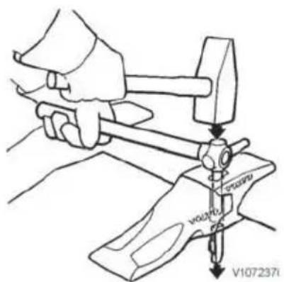
Knock out the locking device
Removing tooth
1 Lower the bucket to the ground and angle it slightly upward.
2 Clean the opening for tooth adapter locking device.
3 Drive out the lock device with a hammer and the special tool or a suitable drift.
4 Remove tooth.

Lock device
A Steel pin
B Lock retainer
Installing tooth
1 Clean the front part of the tooth adapter and the hole for the locking device.
2 Install the tooth so that the guide lugs fit in the tooth adapter recesses.
3 Replace lock retainer (B) with a new part.

The locking device should be just below the scored line.
4 Install the locking device so that the chamfered part points downward and the lock retainer points forward.
5 Knock down the locking device with a hammer until it is level with the upper part of the tooth adapter.
6 Drive down the lock device more with a hammer and the special tool or other suitable drift so that the upper part ends up just below the line marking in the hole.
Replace the steel pin in connection with replacement of tooth adapter.

Hydraulic oil filter clogging
Hydraulic system
Any work on the system requires extreme cleanliness. Even very small particles can cause damage or clog the system. Therefore, wash and wipe clean relevant areas before any work is done.
NOTE!
Do not use the working hydraulics at full speed until the hydraulic oil is warm. The hydraulic oil filter does not filter all of the oil when the oil temperature is below 15 °C (59 °F) at high flow. This can lead to unfiltered oil being pumped out in the system, which may result in noise and/or malfunctions.
NOTE!
If the alarm symbol for clogged hydraulic oil filter remains after the machine has reached sufficient working temperature, the filter may need to be replaced. Contact a workshop authorized by Volvo.
Hydraulic oil
NOTE!
If the machine's hydraulic system is filled with biologically degradable hydraulic oil, the same type of oil must be used when topping up and when changing hydraulic oil. Different types of biologically degradable hydraulic oils may not be mixed. Mineral oil may not be used together with biologically degradable hydraulic oil. When changing from mineral oil to biologically degradable hydraulic oil, contact a workshop authorized by Volvo.
NOTICE
Risk of environmental pollution.
Hydraulic oil is hazardous to the environment. Immediately use barriers to contain spilled oil and follow local regulations concerning hazardous materials.

Hydraulic oil level glass
A Hydraulic oil level glass (lower glass)
B Hydraulic oil filling point
Hydraulic oil level, checking
Check the hydraulic oil level every 10 hours.
1 Place the machine on firm and level ground.
2 Lower the lift arms to the ground.
3 Turn off the engine and apply the parking brake.
4 Open the engine hood.
5 Check the oil level: With cold oil, the lower glass should be filled, but the upper glass should be empty. With warm oil, the oil should not reach higher than to the middle of the upper glass.
6 If necessary, top up through the hydraulic oil filling point (B).
natural_image
Silhouette of a syringe with handle and spout, no text or symbols visibleGreasing
Bearings, greasing
The service life of bushings and pivot pins can be extended considerably, if the machine is greased regularly and in a correct way.
The greasing of bearings has two main purposes:
- Add grease to the bearing to reduce friction between pin and bushing.
- To replace old grease that may contain dirt particles. The grease in the space inside the outer seal collects dirt and prevents dirt and also water from penetrating into the bearing.
Wipe off grease nipples and grease gun before greasing, so that dirt and sand is not introduced through the grease nipples.
Grease the bearing until new grease comes out through the outer seal. Recommended grease, see page 218.
Between 10 and 15 strokes with a normal hand-held grease gun is required to grease one of the bearings for the lifting arms.

Articulation joints, lubricating
Grease the bearing every 10 hours.
V1132385 Greasing points

natural_image
Technical line drawing of a vehicle interior showing a warning box with an exclamation mark and two arrows pointing to the door (no text or symbols present)V1132386
Greasing points
Steering cylinder bearings, lubricating
Grease the bearings every 100 hours.
NOTE!
Grease every 50 hours in aggressive/corrosive environment.
Greasing bearings
1 Lower the lift arms to the ground.
2 Turn off the engine and apply the parking brake.
3 Lift and tilt hydraulics should be without pressure.
4 Clean the grease nipples before greasing.
5 Lubrication is sufficient if grease comes out from the bearing.
For quality of grease, see page 218.
Lifting frame, lubricating
Grease the boom every 100 hours.
NOTE!
Grease daily in tough operating conditions.
1 Lower the lift arms to the ground.
2 Turn off the engine and apply the parking brake.
3 Lift and tilt hydraulics should be without pressure.
4 Clean the grease nipples before greasing.
5 Lubrication is sufficient if grease comes out from the bearing.
For quality of grease, see page 218.
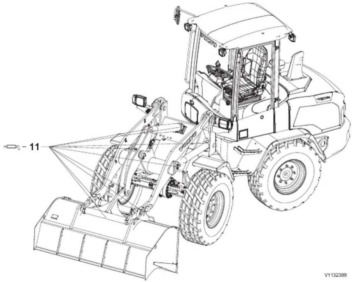
V1132388
Lubrication and service chart
Symbol key
The following standard symbols are used in the lubrication and maintenance chart.

Engine Lubrication

Transmission Grease nipple

Hydraulic system Oil/liquid

Brake system Filters

Axles Air filter

Fuel system Level check

Battery Belt tension

Coolant Control lights

Air conditioning Draining




Some service and maintenance jobs included in the Lubrication and service chart require trained workshop personnel or special equipment. For these jobs we recommend contact with a workshop authorized by Volvo.
Check, oil change and lubrication
Intervals:
Daily (every 10 hours), 50, 100, 250, 500, 1000, 1500, 2000, and 6000 hours (symbol explanation, see page 213).
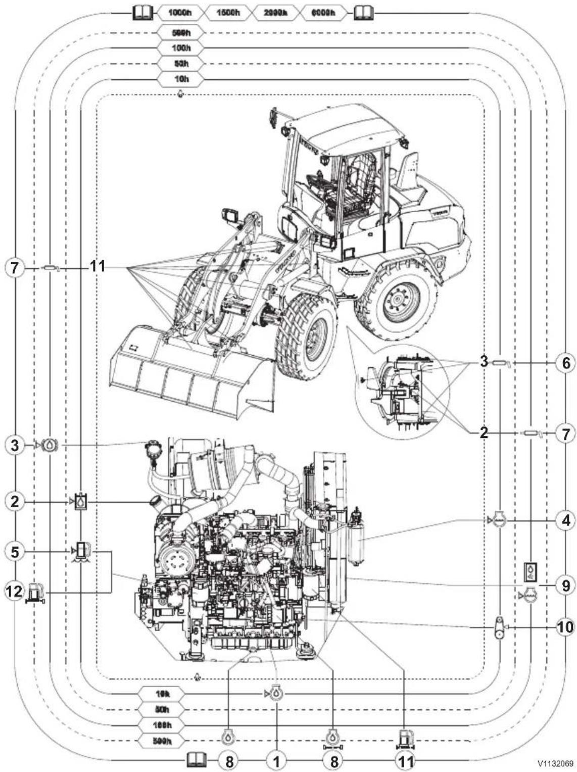
| Pos. | Page=Action | |
| DAILY (every 10 hours) | ||
| Check headlights, work lights, back-up alarm, and function of the control lights. | ||
| Check the Twin filter system (optional equipment) | ||
| 1 | 187 | Check the engine oil level |
| 2 | 208 | Check the hydraulic oil level |
| 4 | 192 | Check the coolant level |
| 5 | 189 | Check the fuel system's water trap (a) |
| 6 | 210 | Grease the articulation joint bearings |
| A = EVERY 50 HOURSAfter performing Daily service | ||
| 200 | Check tires (air pressure and damage) (b) | |
| B = EVERY 100 HOURSAfter performing Daily service and A-service | ||
| 3 | 198 | Check the brake fluid level |
| 7 | 210 | Grease the steering cylinder bearings (c) |
| 7 | 211 | Grease the boom(b)(c) |
| 9 | 193 | Check the engine's radiator, the hydraulic oil cooler, the intercooler, and the air conditioning condenser (d) |
| D = EVERY 500 HOURSAfter performing Daily service, A-, B-, and C-service | ||
| 8=W | Workshop job | Change engine oil and engine oil filter (e) 220. |
| 11=W | Workshop job | Replace the secondary fuel filter (f) |
| 12=W | Workshop job=Replace the primary fuel filter | |
| Workshop job=Check brake pads | ||
| 199 | Check the parking brake | |
| Check for leaks. | ||
a) Check according to signal
b) Check daily if there is a risk of damage to the tires, e.g., when handling sharp rocks.
c) Grease every 50 hours in aggressive/corrosive conditions.
d) Clean at regular intervals. When operating in very dusty conditions, check the radiator/coolers daily.
e) At least once a year. For conditions that have to be met if the interval is to apply, see page
f) At least once a year.
Check, oil change and lubrication
Measures that should be carried out by a workshop at below stated intervals
| EVERY 1000 HOURS |
| Replace the primary air filter (main cartridge)(a) |
| Replace the cab ventilation filter(b) |
| Check the valve clearance |
| EVERY 1500 HOURS |
| Change the oil in the front axle (c) |
| Change the oil in the rear axle with transfer box (c) |
| Replace the hydraulic oil filter (c) |
| Replace the hydraulic system breather filter (c) |
| Change the hydraulic oil (c)(d) |
| Check the crankcase ventilation |
| Check/maintenance of exhaust aftertreatment system components |
| EVERY 2000 HOURS |
| Replace the secondary air filter (safety cartridge) (e) |
| Check coolant mixture |
| Replace the fuel system breather filter |
| EVERY 3000 HOURS |
| Check of turbocharger |
| Check/maintenance of exhaust aftertreatment system components |
| EVERY 6000 HOURS |
| Change the coolant (f) |
a) Replace every 1000 hours, at least once a year, after cleaning max. 5 times, or after signal (if cleaning does not help)
b) The interval between filter replacements can be increased or reduced depending on how dusty the operating conditions are.
c) At least once a year.
d) When using external hydraulic equipment, e.g., road sweeper, drill, snow blower, or similar, the oil should be changed every 1000 hours.
e) Replace every 2000 hours, at least every second year, or when the primary air filter has been replaced max. three times.
f) Change coolant every 6000 hours or at least every fourth year.

Specifications Recommended lubricants
For questions and information about oils, lubricants, and extreme outdoor temperatures, contact your dealer.
NOTE!
Keep in mind the type of engine with which the machine is equipped and follow the instructions that apply to that engine.
NOTE!
It is very important that instructions for oil grade are followed, otherwise deposits from the oil may clog the diesel particulate filter.
| Oil grade Recommended viscosity at varying ambient temperatures | ||||||||||||
| ENGINE Volvo Ultra Diesel Engine Oil VDS-4 or other approved VDS-4 engine oil (a) | °C -30 -20 -10 0 +10 +20 +30 +40 +50°F -22 -4 +14 +32 +50 +68 +86 +104 +122 | |||||||||||
| SAE 10W-30 | ||||||||||||
| SAE 15W-40 | ||||||||||||
| SAE 10W-40 | ||||||||||||
| SAE 5W-30 | ||||||||||||
| SAE 5W-40 | ||||||||||||
| SAE 30 | ||||||||||||
| SAE 40 | ||||||||||||
| V1095849 | ||||||||||||
| ACEA-E9API:CJ-4a) | ||||||||||||
a) Follow the recommended change intervals according to the oil's grade (quality class) and the sulphur content in the fuel, see page 220
| Oil grade Recommended viscosity at varying ambient temperatures | |||||||||||
| HYDRAULIC SYSTEMSteering hydraulicsBrake hydraulicsWorking hydraulics Hydrostatic transmission | Volvo Super Hydraulic Oil Mineral oil based HVLP acc. to DIN 51524-3 ISO 11158: HV or Alternative – Not approved for high speed version: Biodegradable Hydraulic Oil 46.Do not mix with other and mineral oils.For further information contact your Volvo Dealer. | °C -30 -20 -10 0 +10 +20 +30 +40 +50°F -22 -4 +14 +32 +50 +68 +86 +104 +122 | |||||||||
| ISO VG 32 HV | |||||||||||
| ISO VG 46 HV | |||||||||||
| ISO VG 68 HV | |||||||||||
| AXLESAxledifferentialAxleplanetaryhubsTransfer box(TP-versiononly) | Volvo Wet BrakeTransaxle Oil(WB102)API GL-5/LS |  V1084067 V1084067 |
| TRANSFERBOX (HIGHSPEEDVERSIONONLY) | Volvo Ultra Diesel EngineOilVDS-4VDS-3or Engine oilACEA-E6/E9, orAPI CJ-4, orACEA-E3/E4/E5/E7, orAPI CG/CH/CI-4, CI-4Plus, orDHD-1 |  V1109186 V1109186 |
| BRAKESYSTEM(STANDARD VERSION) | Mineral oil specifiedEngine oil, see ENGINE. | |
| BRAKESYSTEM(HIGHSPEED VERSION) | Brake fluidacc. to SAE J 1703, DINISO 4925 DOT 4 (acc. to FMVSS no. 116) |  |
| COOLINGSYSTEM | Volvo Coolant VCSVolvo Coolant VCS should be used only. (Water 50%, anti-freeze 50%),see page 220. | |

Engine oil
NOTE!
It is very important that instructions for oil grade are followed, otherwise deposits from the oil may clog the particle filter (DPF)
| Oil grade | Sulphur content in fuel, in ppm | |
| < 15 ppm | ||
| Oil change interval | ||
| Volvo Ultra Diesel Engine Oil VDS-4 | 500 hours | |
| ACEA: E9API: CJ-4 | 250 hours | |
Coolant
Only use Volvo Coolant VCS when topping up or changing coolant. To avoid damage to engine and cooling system, different coolants or corrosion protection must not be mixed. When using concentrated Volvo Coolant VCS and clean water, the mixture should contain 40–60% concentrated coolant and 60–40% clean water. The amount of concentrated coolant must never be less than 40% of the total mixture, see table below.
| Freeze protection down to Mixed-in amount of concentrated coolant | |
| -25 °C (-13 °F) 40% | |
| -35 °C (-31 °F) 50% | |
| -46 °C (-51 °F) 60% | |
The concentrated coolant must not be mixed with water that contains a high degree of lime (hard water), salt or metals.
The clean water for the cooling system must also meet the following requirements:
| Description Value | |
| Total number of solid particles < 340 ppm | |
| Total hardness < 9.5° dH | |
| Chloride < 40 ppm | |
| Sulphate < 100 ppm | |
| pH value 5.5-9 | |
| Silica < 20 mg SiO | 2 /litre |
| Iron < 0.10 mg Fe/litre | |
| Manganese < 0.05 mg Mn/litre | |
| Electrical conductivity < 500 μS/cm | |
| Organic material, COD-Mn < 15 mg/litre |
If there is any doubt about the water quality use ready-mixed Volvo Coolant VCS, which contains 40% concentrated coolant. Do not mix with any other ready-mixed coolants since this may result in engine damage.
Grease
Volvo Super Grease Lithium EP2
Or corresponding grease on lithium base with EP additives and consistency NLGI class 2.
If the machine is provided with automatic greasing system, other recommended lubricants apply.
Fuel system
Fuel
Fuel recommendations for EU-certified engines (with recirculation of exhausts (EGR) and aftertreatment of exhausts) for models from year 2011.
Diesel engines from 2011 and later are only intended to be run on sulphur-free fuel, with a maximum sulphur content of 10 ppm. Using any other fuel than sulphur-free fuel results in an engine with lower efficiency and shorter service life, permanent damage to advanced emission control devices and systems, inferior fuel economy, and possibly that the engine does not work at all. It is very likely that the manufacturer's warranties will become invalid and void when using unsuitable or incorrect fuels. Correct selection of fuel is decisive for good economy, performance, and engine life. Market fuel that meets EU's standard EN590 for diesel fuel oil should be used. Swedish Mk1-fuel that meets Swedish SS 155435 is also permitted. It is important that the fuel is not contaminated by dust or water since these can cause damage to the fuel system and also increase engine wear.
Fuel recommendations for USA-certified engines (with recirculation of exhausts (EGR) and aftertreatment of exhausts) for models from year 2011.
Diesel engines for model year 2011 and later are designed to only run on fuels with very low sulphur content, Ultra Low Sulphur Diesel (ULSD), with a maximum sulphur content of 15 ppm. Using any other fuel than ULSD results in an engine with lower efficiency and shorter service life, permanent damage to advanced emission control devices and systems, inferior fuel economy, and possibly that the engine does not work at all. It is very likely that the manufacturer's warranties will become invalid and void when using incorrect fuels, and use of other fuels than ULSD in diesel-powered machines is illegal and punishable by provisions of civil law and legislation. Correct selection of fuel is decisive for good economy, performance, and engine life. ASTM D 975 Number 2D ULSD should be used when climate conditions permit. ASTM D 975 Number 1D ULSD can be used in cold weather.
Mixtures of ASTM D 975-fuels Number 1D and Number 2D ULSD can be used to suit different climate conditions. It is important that the fuel is not contaminated by dust or water since these can cause damage to the fuel system and also increase engine wear.
NOTE!
It is very likely that the manufacturer's warranties will become invalid and void when using unsuitable or incorrect fuels.
NOTE!
If you are unsure of what fuel is in the fuel tank, do NOT use the machine
Biodiesel fuel
Vegetable oils and/or esters, also called "biodiesel" (e.g., rape-seed methyl ester, RME fuel), are offered on certain markets both as pure products and as mixed into the diesel fuel.
Volvo CE accepts max. 7% intermix of biodiesel fuel in the diesel fuel, ready-mixed from the oil companies.
Alternative fuels
This statement is only valid for Volvo branded engines, but also includes engines for DD25 and C-series Skid Steer Loaders where warranty is provided by Volvo.
Hydro-treated vegetable oil (HVO) and fatty acid methyl ester (FAME) biodiesel are both made from renewable raw materials such as vegetable oils and animal fats, but they are chemically processed in different ways.
Hydro-treated vegetable oil (HVO)
HVO is created using a chemical process called hydro-treating. Hydro-treating creates an oxygen-free hydrocarbon product that is very similar to distillate diesel fuel and is well suited for use in diesel engines. HVO that conforms to CEN prEN 15940 is approved for use in all Volvo Construction Equipment diesel engines with no changes to maintenance intervals.
Biodiesel
Biodiesel is a product made from renewable resources such as vegetable oils or animal fat. Biodiesel that has been chemically processed into fatty acid methyl ester (FAME) can be blended with distillate diesel fuel and used in some diesel engines. Unblended biodiesel is referred to as B100 because it is 100% biodiesel.
Rapeseed methyl ester (RME) is the most common type of FAME used in Europe. Soy methyl ester (SME) and sunflower oil methyl ester (SOME) are the most common types of FAME used in the US. Although use of FAME biodiesel is now a legal requirement in some markets, it is not as suitable for use in diesel engines as conventional diesel fuel or HVO (hydro-treated vegetable oil).
Biodiesel fuel requirements
The FAME biodiesel blends specified in the table below are approved for use if:
- The biodiesel is pre-blended by the fuel supplier
- The biodiesel used in the blend conforms to EN14214 or ASTM D6751
- The distillate fuel used in the blend meets fuel sulphur requirements
-
The distillate fuel used in the blend conforms to EN590 or ASTM D975
-
B1-B5 biodiesel blends conform to EN590 or ASTM D975
- B6-B7 biodiesel blends conform to EN590 or ASTM D7467
- B8-B20 biodiesel blends conform to ASTM D7467
| Engine emission designation Engine size Acceptable blend | ||
| EU Stage II / US Tier 2 * EU Stage IIIA / US Tier 3 * EU Stage IIIB / US Tier 4 interim EU Stage IV / US Tier 4 final | Below D4 / 4 litres | Up to B7 |
| EU Stage II / US Tier 2 * EU Stage IIIA / US Tier 3 * EU Stage IIIB / US Tier 4 interim EU Stage IV / US Tier 4 final | D4-D8 Up to | B7 |
| EU Stage IIIB / US Tier 4 interim, equipped with High Sulphur Fuel Conversion Kit (only available in unregulated markets) EU Stage IV / US Tier 4 final, equipped with High Sulphur Fuel Conversion Kit (only available in unregulated markets) | ||
| EU Stage II / US Tier 2 * EU Stage IIIA / US Tier 3 * | D9-D16 Up to | B20 |
| EU Stage IIIB / US Tier 4 interim EU Stage IV / US Tier 4 final | D11-D16 Up | to B10 |
| EU Stage IIIB / US Tier 4 interim, equipped with High Sulphur Fuel Conversion Kit (only available in unregulated markets) EU Stage IV / US Tier 4 final, equipped with High Sulphur Fuel Conversion Kit (only available in unregulated markets) | Up to B20 | |
| * As Tier 2 and Tier 3 emissions regulations ended in 2005 and 2010 respectively, engines produced since then typically meet Stage IIStage IIIA regulations, allowing their sale in less regulated markets. | ||
NOTE!
Failures directly caused by the use of poor quality biofuel, or any other fuel not conforming to standards, are not factory defects and the manufacturer's warranty does not apply.
Maintenance interval requirements
Additional service actions and shorter maintenance intervals are mandatory when using biodiesel blends above B10.
| Every 10 hours |
| - Check the engine oil and change if it rises above the maximum fill level- Inspect the fuel system components and replace as necessary |
| Half of original interval |
| - Change the engine oil and filter- Replace the fuel filter(s) |
| Every year, regardless of operating hours |
| - Change the engine oil and filter- Clean the fuel tank |
Effects of biodiesel on engine oil
Using biodiesel can lead to increased oil dilution. Use engine oil analysis tools frequently to check for fuel dilution and monitor engine oil condition. Check the engine oil level daily. Always change the engine oil if the oil level rises above the maximum fill level.
Effects of biodiesel on fuel systems
Biodiesel dissolves and loosens some fuel system deposits. During the initial conversion to biodiesel, loosened deposits will travel to the fuel filters and require more frequent fuel filter replacements. Start with new fuel filters when using biodiesel for the first time.
Biodiesel is aggressive to some materials used in fuel system components. Inspect seals, hoses, rubber and plastic components every 10 hours. Repair or replace any components that are damaged, softened or leaking. Clean biodiesel from painted surfaces immediately to prevent paint damage.
Biodiesel is more sensitive to bacteria and water contamination than distillate diesel fuel.
- Use as much fuel as possible before refilling the fuel tank in order to prevent bacteria growth if a machine is in regular use, e.g. regularly uses up a tank of fuel within a week. In climates where condensation is a risk, or when the machine is working for short durations, keep the fuel tank full.
- Do not use biodiesel in machines with low utilization or operating time.
- Do not store machines for more than 4 weeks without flushing biodiesel out of the fuel system by operating the machine through at least one full tank of distillate diesel fuel.
- Always follow the manufacturer's storage recommendations and "best-before" dates for each delivery of biodiesel.
Effects of biodiesel on exhaust after-treatment systems
Biodiesel leaves higher levels of ash in diesel particulate filters and may require more frequent diesel particulate filter (DPF) regeneration and cleaning. Biodiesel can cause deviations in temperatures and functionality of the DPF burner and may cause fault codes or errors.
Biodiesel exhaust gas is aggressive to some materials used in selective catalytic reduction systems (SCR) and may require more frequent cleaning, repairing or replacing of SCR parts.
Effects of biodiesel on cold weather operation Biodiesel has a high viscosity at temperatures below 0 °C (32 °F) and may cause problems starting the engine. Use a fuel heater or park machines in a heated building if possible.
Effects of biodiesel on emissions compliance Engines are certified to comply with U.S. EPA, California and EU emissions standards based upon the use of test fuels with specifications established by these regulatory agencies. Alternative fuels, including biodiesel, that are not substantially similar to the required test fuels may adversely affect engine emissions compliance. As a result, Volvo does not warrant that the engine will conform to applicable Federal or California and EU emissions limits when operated on, or having previously being operated on, biodiesel or other alternative fuels that are not substantially similar to specified test fuels used for certification,
nor if biodiesel / regular diesel is used in blends that exceed the recommendations.
Service capacities and change intervals
Change capacities
| Oils and fluids Filling capacities | |
| Engine, incl. filter 11.2 litres (3 US gal) | |
| Front axle 12.2 litres (3.2 US gal) | |
| Rear axle incl. gearbox 13.5 litres (3.6 US ga) | |
| Hydraulic system, incl. tank 54 litres (14.3 US gal) | |
| Fuel tank 84 litres (22.2 US gal) | |
| Coolant 11 litres (2.9 US gal) |
Change intervals
| Oil and fluid changes | Change intervals*) |
| Engine oil(a) | 500 operating hours |
| Front axleRear axle with transfer boxa) | 1500 operating hours |
| Hydraulic oil a) | 1500 operating hours |
| Brake fluid At least every second year | |
| Coolant (VCS coolant)(b) | 6000 operating hours |
| Filter replacements | Change intervals*) |
| Engine, oil filter a) | 500 operating hours |
| Fuel filter, primary(c) | 500 operating hours |
| Fuel filter, secondary c) | 500 operating hours |
| Air cleaner, primary filter According to signal, | at least once a year,or if it has been cleaned max. 5 times |
| Air cleaner, secondary (safety) filter Every 3rd | primary filter replacement or atleast every second year |
| Hydraulic oil filter and breather filter a)(d) | 1500 operating hours |
| Oil separator element 1500 operating hours | |
| Fuel tank, breather filter 2000 operating hours | |
a) At least once every year.
b) At least every fourth year.
c) At least once every year, or when replacing the engine oil filter, which may mean a shorter interval.
d) When using external hydraulic equipment, e.g. road sweeper, drill, snow blower or similar, the oil should be changed every 1000 hours.
*) These intervals apply under normal operating conditions and the recommended fuels and lubricants.
Engine
| Model D3.3H (DPF-engine) D3.3M (DOC-engine) | |
| Make 4-stroke diesel engine with direct injection, turbocharger, electronic control and DPF. | 4-stroke diesel engine with direct injection, turbocharger, electronic control and DOC. |
| Model V3307-CR-TE4B V3307-CR-TIE4B | |
| Designation D3.3H D3.3M | |
| Emission certification TIER 4f, Stage 3b TIER 4f, Stage 3b | |
| Type 4 cylinders 4 cylinders | |
| Aspiration type Turbo charged Turbo charged | |
| Max. power at 2600 rpm, SAE J1995, gross 55,4 kW (75 hp) 55,4 kW (75 hp) | |
| Max. torque at 1500 rpm, gross 265 Nm (195 ft lb) 265 Nm (195 ft lb) | |
| Low idle speed 950 rpm | 950 rpm |
| High idle speed 2800 rpm | 2800 rpm |
| Lubrication system, type forced-feed oil lubrication | forced-feed oil lubrication |
| Air cleaner 2-stage | 2-stage |
Electrical system
| System voltage 12 V | |
| Battery 1 pc | |
| Battery voltage 12 V | |
| Battery capacity 100 Ah | |
| Alternator, rated output 1.26 kW (1.71 hp) | |
| Alternator, current rating 90 A | |
| Starter motor output 3.0 kW (4.1 hp) |
| Bulbs Watt Socket | ||
| Head lights:- Travel lights, low beam- Travel lights, high beam | —65 W H770 W H3 | —PX 26 dPK 22 S |
| Parking lights:- Front- Rear | —T 4 W/R 10 WT 4 W/R 10 W | — |
| Number plate light R 10 W BA 15 s | ||
| Tail lights R 10 W BA 15 s | ||
| Brake lights P 21 W BA 15 s | ||
| Direction indicators, front/rear | P 21 W/P 21 W BA 15 s | |
| Interior light P 21 W BA 15 s | ||
| Working lights 55 W H3 | PK 22 s | |
| Rotating warning beacon | 70 W H1 and 5 W | PK 14.5 s |
| Backup lights | P 21 W BA 15 s | |
Relays and fuses in the engine compartment
NOTE!
Only use fuses with stated capacity (Ampere rating).
Risk of damaging or burning!

| Relays in the engine compartment (near the batteries located under the rubber flap) | |||||
| RE A | Function RE A Func | tion | |||
| 3301 | 70 Starter motor 2501 70 Pre-heating | ||||
| Fuses in the engine compartment | |||||
| FU A | Function | FU A Function | |||
| FU70 | 80 Main fuse (power supply for cab) | FU72 | 40 Starter motor | ||
| FU71 | 60 Pre-heating | FU73 30 Power outlet 12V | |||
Relays and fuses in the cab
NOTE!
The relays and fuses in the cab are located at the circuit board

| RE8701 | 30A Climate control system |
| RE4235 | 20A Engine braking (optional equipment |
| RE3504 | 20A Working lights front |
| RE3505 | 20A Working lights rear |
| RE9122 | 40A Automatic tilt |
| RE9123 | 40A Automatic lift |
| RE9171 | 40A 3rd to 4th function single lever |
| FU87 30A Condenser fan | |
| FU89 10A Working lights front | |
| FU90 10A Working lights rear | |
Relays and fuses on the circuit board
Relays

V1132794
| Relays | |||||
| RE | A | FUNCTION | RE A FUNCTION | ||
| 01 | 50 | Ignition 15A | 06 50 Working lights | ||
| 02 | 50 | Ignition 15B | 07 50 Cab fan & climate | control | |
| 03 | 40 | Ignition 15EA | 09 40 Water in fuel | ||
| 04 | 40 | Windscreen wiper front | RF3601 | 2/4 x 21W Flasher | |
| 05 | 40 | Reverse alarm & lights | |||
Fuses

V1132794
| Fuses | |||||
| FU | A | FUNCTION | FU | A | FUNCTION |
| 06 | 15 | Ignition switch | 27 | 10 | Exciting current alternator |
| 07 | 40 | Ignition (15B) | 28 | 10 | Caretrack ECU, w per front |
| 08 | 40 | Ignition (15A) | 29 | 10 | Position lights |
| 09 | 10 | Radio | 30 | 10 | Position lights |
| 10 | 10 | Hazard warning switch | 31 | 15 | Working light front |
| 12 | 10 | Interior light, rotating beacon | 32 | 15 | Working light rear |
| 13 | 40 | Working lights front + rear | 35 | 10 | Drive light right |
| 14 | 15 | switch position lights, horn | 36 | 10 | Drive light left |
| 15 | 15 | Fuel preheating/water indicator, socket | 37 | 10 High beam right | |
| 16 | 20 | Fan cab heating | 38 | 10 | High beam left, control light |
| 17 | 10 | 39 | Pre heating control light | ||
| 18 | 15 | Switch flashing lights | 40 | 5 | Switch air conditioning |
| 19 | 5 | Joystick | 41 | 30 | 15EA supply |

| Fuses | |||||
| FU | A FUNCTION FU A FUNCTION | ||||
| 20 | 10 Fuel preheating, sensor servo pressure 0,5 MPA (BSS), sensor boom positioning (BSS, | 43 | 10 — | ||
| 21 | 25 V-ECU 44 10 I-ECU / Keypad | ||||
| 22 | 15 Fuel supply pump, engine ECU, EGR-valve, air mass/ ambient temperature sensor, pre heating relay | 45 | 10 B | Brake light | |
| 23 | 10 Reverse lights, opt/acoust. Reverse Alarm | 46 | 10 W | Windscreen wiper/Washer read | |
| 24 | 10 Switch indicator 47 20 Suspensioned heated | seat, sensor seat contact, pre fuse joystick, engine brake footswitch, relay, switch additional pump, switch attachment bracket rear, | |||
| 25 | 15 drive light 48 10 Heatable mirrors | ||||
| 26 | 15 Road sweeper, working hydraulic, control cab heating/AC | ||||
Transmission
Hydrostatic travel system
| Hydrostatic travel system (standard version) | |
| Travel speeds | |
| 1st gear (“turtle”) 0-6 km/h (0-3.7 mph) | |
| 2nd gear (“rabbit”) 0-20 km/h (0-12.4 mph) | |
| Hydrostatic travel system (TPS-version) | |
| Travel speeds | |
| 1st gear (“turtle”) 0-7.5 km/h (0-4.7 mph) | |
| 2nd gear (“rabbit”) 0-30 km/h (0-18.6 mph) | |
Front axle
| Type Fixed mounted | |
| Differential lock, type 100%, dog clutch |
Rear axle
| Type Fixed mounted | |
| Differential lock, type 100%, dog clutch |
Brake
| Service brake, type (Standard version) | Drum brake at drop box. Single circuit brake system. |
| Service brake, type (High speed version) | Dry disc brake on front axle input flange.Single circuit brake system. |
| Inching brake pedal (TP-version) Hydraulic | inching brake pedal for infinitely variable control of travel speed and service brake application. Double pedal arrangement. |
| Inching brake pedal (TPS-version) Electronic | inching brake pedal for infinitely variable control of travel speed and service brake application. Double pedal arrangement. |
| Parking brake, type Drum brake on drop-box. | Box. Hand lever operation. |
Steering
| Steering system, type Articulated frame | steering with Hydrostatic steering unit open centre acted |
| Steering pump, type Gear pump | |
| Steering cylinder 1 pc | |
| Steering angle ±40° |
Wheels
| Tires | unit | L30G L35G | |||
| front rear | front rear | ||||
| 12.5 - 20 bar 2,75 2,5 | 3,25 2,5 | ||||
| psi 39,89 | 36,26 47,14 | 36,26 | |||
| 13.5 - 20 bar 3 2,25 3 | 5 2,5 | ||||
| psi 43,51 | 32,63 50,76 | 36,26 | |||
| 14.5 - 20 bar 2,5 2,25 | 3 2,25 | ||||
| psi 36,26 | 32,63 43,51 | 32,63 | |||
| 15.5/55 R18 bar 4 3 4 | 5 3,5 | ||||
| psi 58,02 | 43,51 65,27 | 50,76 | |||
| 16/70-20 bar 2,25 1,75 | 2,5 1,75 | ||||
| psi 32,63 | 25,38 36,26 | 25,38 | |||
| 17.5/65-20 bar 2,75 1 | 75 3 2 | ||||
| psi 39,89 | 25,38 43,51 | 29,01 | |||
| 9.00 R20 *) bar 3 3 3 | 5 3 | ||||
| psi 43,51 | 43,51 50,76 | 43,51 | |||
| 335/80 R18 bar 3,75 2 | ,75 — — | ||||
| psi 54,39 | 39,89 — — | ||||
| 335/80 R20 bar 3,25 2 | ,75 3,75 3,5 | ||||
| psi 47,14 | 39,89 54,39 | 50,76 | |||
| 340/80 R20 bar 3,25 2 | ,75 3,75 3,25 | ||||
| psi 47,14 | 39,89 54,39 | 47,14 | |||
| 360/80 R20 bar 2,5 2 | 25 3 2,75 | ||||
| psi 36,26 | 32,63 43,51 | 39,89 | |||
| 365/70 R18 bar 3,5 2 | 75 — — | ||||
| psi 50,76 | 39,89 — — | ||||
| 365/80 R20 bar 3 2,5 | 3,5 2,75 | ||||
| psi 43,51 | 36,26 50,76 | 39,89 | |||
| 375/75 R20 bar 2,5 2 | 3,25 2,5 | ||||
| psi 36,26 | 29,01 47,14 | 36,26 | |||
| 400/55-22,5 bar 2,5 2 | 2,75 2,25 | ||||
| psi 36,26 | 29,01 39,89 | 32,63 | |||
| 400/70 R18 bar 3 2,25 | 3,5 2,75 | ||||
| psi 43,51 | 32,63 50,76 | 39,89 | |||
| 400/70 R20 bar 2,75 2 | ,25 3,25 2,75 | ||||
| psi 39,89,25 3 2,5 | 32,63 47,14 | 39,89 | |||
| 400/70 R24 bar 2,75 2 | |||||
| psi 39,89 | 32,63 43,51 | 36,26 | |||
| 405/70 R18 bar 3 2,25 | 3,5 2,75 | ||||
| psi 43,51 | 32,63 50,76 | 39,89 | |||
| 405/70 R20 bar 2,75 2 | ,25 3 2,5 | ||||
| psi 39,89 | 32,63 43,51 | 36,26 | |||
| 420/65 R24 bar 2,5 2 | 3 2,25 | ||||
| psi 36,26 | 29,01 43,51 | 32,63 | |||
| 425/75 R20 bar 2,25 2 | 2,5 2,25 | ||||
| psi 32,63 | 29,01 36,26 | 32,63 | |||
| 455/70 R20 bar 2,25 1 | ,75 2,5 2 | ||||
| psi 32,63 | 25,38 36,26 | 29,01 | |||
| 500/45-22.5 bar 2,25 1 | ,75 2,5 2 | ||||
| psi 32,63 | 25,38 36,26 | 29,01 | |||
| 550/45-22.5 bar 2 1,5 | 2,25 1,75 | ||||
| psi 29,01 | 21,76 32,63 | 25,38 | |||
*) Solid rubber tires that must be cooled down after road transport. After one hour and maximum 6 km covered distance, stop the machine to allow the tires to cool down 15 minutes.
The stated tyre pressures are guide values.
- If L4 or L5 tyres are used for loading-carrying operations, due attention must be paid to the transporting distances.
Radial tyres are to be preferred for loading-carrying operations, as the build-up of heat is less in this type of tyre.
If other tires are used than those stated, the tire manufacturer should be contacted for information about the correct tire pressure.
All tires in the table are not available on all markets. Contact your dealer for more information.
Cab
| General | |
| The cab is installed on rubber pads, is insulated, and has a flat floor with rubber mat. | |
| Tested and approved as a protective cab and meets standards according to ISO 3471-1994 and SAE 1040-MAY 94 (ROPS), ISO 3449-2005 (FOPS). | |
| Emergency exit Right hand side door | |
| Heating and ventilation | |
| Heating and ventilation system with air conditioning and engine-independent diesel heater available as optional equipment. | |
| Operator seat | |
| This machine is equipped with an operator seat that meets the criteria for EN ISO 7096. | |
Hand and arm vibrations
The hand and arm vibrations generated during real operating conditions, if the machine is used as intended, is less than 2.5 m/s 2 RMS (root mean square) acceleration according to ISO 8041.
Whole-body vibrations
Whole-body vibrations generated during real operating conditions, if the machine is used as intended, is according to the following table.
| Typical operating conditions Vibration | emission, value aw,eqx (m/s2 RMS) | Vibration emission, value aw,eqy (m/s2 RMS) | Vibration emission, value aw,eqz (m/s2 RMS) |
| V-shaped loading and carrying work 0.6 0.6 0.6 | |||
| Loading and carrying work 0.5 0.5 0.6 | |||
| V-shaped loading and carrying work with pallet fork | 0.5 0.5 | 0.5 | |
| Transporting operation 0.5 0.5 0.6 |
The following vibration directions are defined:
x = fore-aft
y = lateral
z = vertical
NOTE!
These values for generated whole-body vibrations were determined at special operating and ground conditions. Therefore they are not representative for all different conditions according to the intended use of the machine and should not be used as the only source to determine the whole-body vibrations to which an operator is exposed when using the machine. For this purpose, we recommend the information in ISO/CEN Technical Report.
To ensure that the generated whole-body vibrations are kept to the lowest possible value, see page 126.
Sound information
| Sound pressure level (LpA) at operator's position(Measurement method according to ISO 6396) | 75 dB(A) |
| Sound power level (LWA) around the machine(Requirement of 2000/14/EC with applicableappendices and measurement method accordingto ISO 6395) | 99 dB(A) (for machines with D3.3H-engine)101 dB(A) (for machines with D3.3M-engine) |
Hydraulic system
Working hydraulics
| Type Open-centre system with main control valve pilot-operated |
| Tilt cylinder 1 pc., double-acting |
| Lifting cylinders 2 pcs., double-acting |
| Cycle times L30G L35G | ||
| Lift-up (empty bucket) 6.0 sec. 6.0 sec. | ||
| Tipping 1.5 sec. 1.5 sec. | ||
| Lift-down (empty) 4.2 sec. 4.2 sec. |
Machine weights
L30G
| Operating weightThe operating weight is the machine's most common configuration + 10%.The machine's most common configuration includes:- Bucket (hook-on) 1.4 m3 (1.8 yd3)- Tires 15.5 R25 L3- Standard boom with TPV attachment carrier- Operator and all fluids | 6000 kg(13228 lb) |
| Max. machine weightMax. machine weight (incl. equipment and attachment)(1) | 6650 kg(14661 lb) |
L35G
| Operating weightThe operating weight is the machine's most common configuration + 10%.The machine's most common configuration includes:- Bucket (hook-on) 1.6 m3 (2.1 yd3)- Tires 17.5 R25 L3- Standard boom with TPV attachment carrier- Operator and all fluids | 6480 kg(14286 lb) |
| Max. machine weightMax. machine weight (incl. equipment and attachment)(1) | 7200 kg(15873 lb) |
Dimensions
L30G with Z-linkage and Z-attachment carrier

| Data with loading forkDistance to centre of gravity 500 mm(20 in) | ||
| Tipping load at full turn | kg (lb) | 3000 (6614) |
| Payload acc. to EN 474-3, 60/80% | kg (lb) | 1800/2400(3968/5291) |
| Payload 80%, transport position, 40°full turn | kg (lb) | 2500 (5512) |
L35G with Z-linkage and Z-attachment carrier
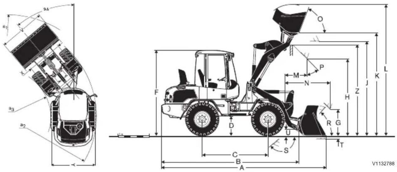
| Data with loading forkDistance to centre of gravity500 mm (20 in) | FEM II | FEM III | |
| Tipping load at full turn | kg (lb) | 3340 (7363) | 3300 (7275) |
| Payload acc. to EN 474-3,60/80% | kg (lb) | 2000/2500(4409/5512) | 2000/2600(4409/5732) |
| Payload 80%, transport position, 40° full turn | kg (lb) | 2500 (5512) | 2800 (6173) |
L35G with TP-linkage and Z-attachment carrier

| L35GT with TP-linkage, Z-attachment carrier and 405/70 R20 tires | |
| B 4600 mm 181 in R 50°C 2150 mm 85 in S 58°D 580 mm 23 in U 250 mm 10 inF 2715 mm 107 in X 1532 mm 60 inG 900 mm 35 in Y 1932 mm 76 inJ 3100 mm 122 in Z 3020 mm 119 inK 3350 mm 132 in aO 63° aP 45° a | 2 3960 mm 156 in3 1980 mm 78 in4 ±40° |
| Data according to bucket type General purpose bucket | Multi-purpose bucket | |||
| L35GT with TP-linkage, Z-attachment carrier and 405/70 R20 tires | Units | With teeth Without teeth | ||
| Capacity heaped m3 1,0 | 1,2 | 0,9 | ||
| yd3 | 1,3 | 1,6 | 1,2 | |
| Material density | kg/m3 | 1800 1500 1900 | ||
| lb/yd3 | 3034 2528 3203 | |||
| Static tipping load, straight (ISO / DIS) | kg | 4200 4150 3900 | ||
| lb | 9259 9149 8598 | |||
| Static tipping load, full turn 40° (ISO / DIS) | kg | 3700 3650 3450 | ||
| lb | 8157 8047 7606 | |||
| Hydraulic lifting capacity, max. | kN | 57,0 | 55,5 | 54,0 |
| lbf | 12814 | 12477 | 12140 | |
| Data according to bucket type General purpose bucket | cket | Multi-purpose bucket | ||
| Breakout force kN 62,5 | 54,5 59,0 | |||
| lbf 140 | 51 12252 13264 | |||
| A mm 5425 5525 5465 | ||||
| in 214 | 218 215 | |||
| L mm 4290 4330 4200 | ||||
| in 169 | 170 165 | |||
| V mm 2000 2000 2000 | ||||
| in 79 | 79 79 | |||
| ∅a1 mm 8670 8730 8700 | ||||
| in 341 | 344 343 | |||
| T | m | m 9 | 0 | |
| in 4 | 4 | 4 | ||
| H | mm 26 | 10 2535 2560 | ||
| in 103 | 100 101 | |||
| M | mm 72 | 5 785 715 | ||
| in 29 | 31 28 | |||
| N | mm 15 | 45 1605 1535 | ||
| in 61 | 63 60 | |||
| Operating weight | kg 610 | 0 6120 6285 | ||
| lb 134 | 48 13492 13856 | |||
| Data with loading forkDistance to centre of gravity 500 mm(20 in) | ||
| Tipping load at full turn | kg (lb) | 2930 (6460) |
| Payload acc. to EN 474-3, 60/80% | kg (lb) | 1750/2300(3858/5071) |
| Payload 80%, transport position, 40°full turn | kg (lb) | 2500 (5512) |
L35G with TP-linkage and V-attachment carrier
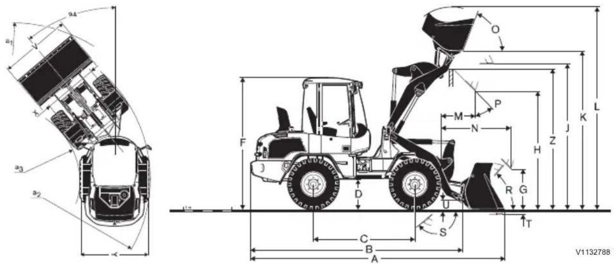
| L35GT with TP-linkage, V-attachment carrier and 405/70R20 tires | |
| B 4600 mm 181 in R 50°C 2150 mm 85 in S 58°D 580 mm 23 in U 250 mm 10 inF 2715 mm 107 in X 1532 mm 60 inG 850 mm 33 in Y 1932 mm 76 inJ 3100 mm 122 in Z 3100 mm 122 inK 3350 mm 132 in aO 63° aP 45° a | 2 3960 mm 156 in3 1980 mm 78 in4 ±40° |
| Data according to bucket type General purpose bucket | Multi-purpose bucket | |||
| L35GT with TP-linkage, V-attachment carrier and 405/70R20 tires | Units | With teeth Without teeth | ||
| Capacity heaped m3 1,0 | 1,2 | 0,9 | ||
| yd3 | 1,3 | 1,6 | 1,2 | |
| Material density | kg/m3 | 1800 1400 1800 | ||
| lb/yd3 | 3034 2360 3034 | |||
| Static tipping load, straight (ISO / DIS) | kg | 4500 3900 3750 | ||
| lb | 9921 8598 8267 | |||
| Static tipping load, full turn 40° (ISO / DIS) | kg | 3600 3450 3300 | ||
| lb | 7937 7606 7275 | |||
| Hydraulic lifting capacity, max. | kN | 52 | 50 | 49 |
| lbf | 11690 | 11353 | 11016 | |
| Data according to bucket type General purpose bucket | cket | Multi-purpose bucket | ||
| Breakout force kN 54 48 | 52 | |||
| lbf 122 | 52 10903 11578 | |||
| A mm 5525 5625 5560 | ||||
| in 218 | 221 219 | |||
| L mm 4250 4390 4260 | ||||
| in 167 | 173 168 | |||
| V mm 2000 2000 2000 | ||||
| in 79 | 79 79 | |||
| ∅a1 mm 8730 8800 8760 | ||||
| in 344 | 346 345 | |||
| T | m | m | 8 | |
| in 3 | 3 | 3 | ||
| H | mm 2550 2470 2490 | |||
| in 100 | 97 98 | |||
| M | mm 800 855 785 | |||
| in 31 | 34 31 | |||
| N | mm 1620 1675 1600 | |||
| in 64 | 66 63 | |||
| Operating weight | kg 6200 6240 6390 | |||
| lb 13669 13757 14088 | ||||
| Data with loading forkDistance to centre of gravity 500 mm(20 in) | ||
| Tipping load at full turn | kg (lb) | 2750 (6063) |
| Payload acc. to EN 474-3, 60/80% | kg (lb) | 1650/2200(3638/4850) |
| Payload 80%, transport position, 40°full turn | kg (lb) | 2500 (5512) |
Service history
| Service 100 hours Type of service Signature and stamp | ||
| Date Hours | ||
| Service 500 hours Type of service Signature and stamp | ||
| Date Hours | ||
| Service 1000 hours Type of service Signature and stamp | ||
| Date Hours | ||
| Service 1500 hours Type of service Signature and stamp | ||
| Date Hours | ||
| Service 2000 hours Type of service Signature and stamp | ||
| Date Hours | ||
| Service 2500 hours Type of service Signature and stamp | ||
| Date Hours | ||
| Service 3000 hours Type of service Signature and stamp | ||
| Date Hours | ||
| Service 3500 hours Type of service Signature and stamp | ||
| Date Hours | ||
| Service 4000 hours Type of service Signature and stamp | ||
| Date Hours | ||
| Service 4500 hours Type of service Signature and stamp | ||
| Date Hours | ||
| Service 5000 hours Type of service Signature and stamp | ||
| Date Hours | ||
| Service 5500 hours Type of service Signature and stamp | ||
| Date Hours | ||
| Service 6000 hours Type of service Signature and stamp | ||
| Date Hours | ||
| Service 6500 hours Type of service Signature and stamp | ||
| Date Hours | ||
| Service 7000 hours Type of service Signature and stamp | ||
| Date Hours | ||
| Service 7500 hours Type of service Signature and stamp | ||
| Date Hours | ||
| Service 8000 hours Type of service Signature and stamp | ||
| Date Hours | ||
| Service 8500 hours Type of service Signature and stamp | ||
| Date Hours | ||

| Service 9000 hours Type of service Signature and stamp | ||
| Date Hours | ||
| Service 9500 hours Type of service Signature and stamp | ||
| Date Hours | ||
| Service 10000 hours Type of service Signature and stamp | ||
| Date Hours | ||
| Service 10500 hours Type of service Signature and stamp | ||
| Date Hours | ||
| Service 11000 hours Type of service Signature and stamp | ||
| Date Hours | ||
| Service 11500 hours Type of service Signature and stamp | ||
| Date Hours | ||
| Service 12000 hours Type of service Signature and stamp | ||
| Date Hours | ||
Alphabetical index
A
Accidents.... 84
Air conditioning.... 204
Air suspended seat (optional equipment)68
Alternative fuels.... 224
Anti-theft device (optional equipment).... 14
Arrival Inspection.... 181
Articulation joints, lubricating.... 210
Attachment brackets.... 135
Attachments.... 132
Auto engine shutoff (optional equipment)77
Automatic lift (boom kick-out)......66
Automatic tilt (bucket positioner)......64
B
Batteries....195
Battery disconnect switch.... 196
Battery, charging....196
Bearings, greasing 210
Before service, read....168
Brake....238
Brake fluid level, checking.... 198
Brake pads, checking....199
Brake system.... 11, 198
Braking....97
Bucket teeth.... 206
Bucket teeth, replacing.... 206
Buckets.... 142
C
Cab.... 12, 202, 242
Cab ventilation filter, cleaning and replacing.... 202
Cab's emergency exits....12
CareTrack (optional equipment)...... 14
CE-marking, EMC-directive.... 15
Change capacities.... 228
Change intervals.... 228
Check, oil change and lubrication. 214, 217
Cleaning engine compartment...... 184
Cleaning machine.... 181
Climate control system....71
Communication equipment, installation.. 21
Condenser, cleaning 204
Controls....54
Coolant....192, 220
Coolant level, checking.... 193
Cooling system.... 192
D
Delivery Inspection....181
Delivery Instructions....181
Dimensions.... 246
Display unit.... 43
Driveline shutoff.... 78
E
Eco driving.... 124
Electrical system.... 11, 195, 231
Engine....10, 187, 230
Engine air cleaner.... 191
Engine block heater.... 96
Engine oil.... 220
Engine oil level, checking....187
Engine protection - Software....77
Environmental requirements.... 10
Equipment....13
EU conformity certificate.... 17
Exhaust aftertreatment system...... 10, 98
F
Fire prevention.... 171
FOPS and ROPS.... 12
Frame....10
Fuel 222
Fuel system....188, 222
Fuel system, air bleeding.... 189
Fuel, filling....82, 188
G
Grease.... 221
Greasing.... 210
H
Handling hazardous materials.... 174
Handling line, tubes and hoses....179
Heater Engine-independent.... 72
Hydraulic function, 3rd and 4th.... 139
Hydraulic function, 4th switchable
from 3rd....156
Hydraulic oil 208
Hydraulic oil level, checking....209
Hydraulic system....12, 208, 244
|
Information and warning decals.... 25
Instrument panel, front.... 32
Instrument panel, side....51
Intended use.... 9
L
Lifting fork operation / Hose rupture (optional equipment).... 63
Lifting frame, lubricating....211
Lifting objects.... 160
Loading.... 141
Logged machine data.... 14
Lubrication and service chart.... 213
M
Machine operator safety.... 84
Machine weights.... 245
Material handling arm.... 157
Measures before operating.... 92
Measures when getting stuck.... 115
Modifications.... 13
O
Operating on public roads....86
Operator comfort....67
Operator obligations....83
Operator seat.... 67
P
Paint finish maintenance....182
Pallet forks.... 150
Parking....113
Parking brake, checking of function..... 199
Perform a regeneration.... 109
Power lines, minimum clearance.... 89
Pressure release....140
Product plates.... 23
Propeller shaft....79
R
Radiator, cleaning.... 194
Recommended lubricants.... 218
Relays and fuses.... 197
Retrieving and towing.... 116
Road sweeping (optional equipment)... 159
Rotating attachments.... 133
Running-in instructions.... 77
S
Safety components.... 22
Safety rules in case of fire....87
Safety rules when operating.... 82
Salt sprayer....154
Seat belt....69
Separate attachment locking.... 137
Service capacities and change intervals228
Service history.... 180, 254
Service points.... 186
Service position....165
Service Programme.... 181
Signalling diagram.... 162
Special hydraulics.... 156
Starting engine....93
Steering....239
Steering cylinder bearings, lubricating.. 211
Steering system.... 12
Stopping....112
Symbol key.... 213
T
Tiltable rear attachment bracket..... 135
Timber grapples.... 153
Touch-up painting.... 183
Transmission....11, 237
Transporting machine.... 119
Travelling on public roads.... 86
Tyres, checking air pressure....200
U
Underground cables and pipes.... 128
V
Visibility.... 79
W
Washer reservoir....203
Water separator, draining.... 190
Welding.... 197
Wheel bolts, checking tightening...... 201
Wheels.... 200, 240
Whole-body vibrations.... 126
Windscreen wiper system.... 203
Working in cold weather....131
Working in water and on boggy ground 129
Working on slopes.... 128
Working where there is risk of landslip. 130
Working with pallet forks.... 151
Working within dangerous areas......128



- Foreword
- NOTE!
- OPERATOR'S MANUAL
- Safety regulations
- DANGER
- WARNING
- CAUTION
- NOTICE
- Identification numbers
- Model-specific information
- Table of contents
- Foreword 1
- Presentation 9
- Instrument panels 31
- Other controls 54
- Operating instructions 77
- Operating techniques 123
- Safety when servicing 164
- Service and maintenance 180
- Specifications 218
- Alphabetical index 257
- Presentation
- Intended use
- Operating underground
- Environmental requirements
- Frame
- Engine
- Exhaust aftertreatment system
- Electrical system
- Transmission
- Brake system
- Service brakes:
- Steering system
- Cab
- Cab's emergency exits
- FOPS and ROPS
- Hydraulic system
- Equipment
- Modifications
- Anti-theft device (optional equipment)
- Logged machine data
- CareTrack (optional equipment)
- CE-marking, EMC-directive
- CE marking
- EU EMC Directive
- EU conformity certificate
- Communication equipment, installation
- Protection against electromagnetic interference
- Guidelines
- Safety components
- Safety-classified machine and spare parts
- Examples of safety-classified machine parts/ spare parts
- Product plates
- Information and warning decals
- Instrument panels
- Keypad
- Work lights (#2 (front) and #5 (rear))
- Reversible fan (#3) (optional equipment)
- Hand throttle (#4)
- Separate attachment lock
- Working hydraulics lock / control lever lockout
- Hazard flashers
- Ignition
- Regeneration (only with engine model D3.3H)
- Semi-automatic regeneration
- Two-position switch:
- Manual regeneration (optional equipment)
- Wiper and washer, rear window
- Headlights
- Three-position switch:
- Headlights, daytime running (optional equipment)
- Rotating beacon (optional equipment)
- Back-up alarm (optional equipment)
- Electrically heated rear-view mirrors (optional equipment)
- Tiltable rear attachment bracket (optional equipment)
- Lift fork operation/Hose rupture protection (optional equipment)
- Information display unit
- Central warning (red)
- Left direction indicators
- Right direction indicators
- Forward travel direction indicator (amber)
- Reverse travel direction indicator (amber)
- High speed
- Applied parking brake
- Engine oil pressure low (red)
- Seatbelt unfastened (red)
- Information screen
- High beams
- Engaged differential lock
- Regeneration (only with engine model D3.3H)
- High exhaust temperature (only with engine model D3.3H)
- Coolant temperature
- Fuel level
- Display unit
- Start sequence
- Anti-theft system (optional equipment)
- Enter code screen
- Recovery code screen
- Change secondary code
- Change primary code
- Main screen
- Subscreens
- Machine speed (optional equipment)
- Machine hours and daily hours
- Machine hours left before service
- Number of bucket cycles (optional equipment)
- Check symbols on the display unit
- Fuel level low
- Preheating malfunction
- Engine coolant temperature high
- Engine failure
- Time to service
- Attachment bracket verification (optional equipment)
- Hydraulic oil filter clogged
- Engine air cleaner clogged
- Hydraulic oil temperature low
- Hydraulic oil temperature high
- Auto engine shutdown (optional equipment)
- Warning symbols on the display unit
- Battery charge error
- Preheating failure
- Water-in-fuel
- Computer failure
- Engine / machine speed too high
- Attachment bracket (ready to connect/disconnect attachment) (optional equipment)
- Engine oil pressure low
- Instrument panel, side
- Automatic lift (boom kick-out) (optional equipment)
- Automatic tilt (bucket positioner) (optional equipment)
- High flow auxiliary hydraulics (optional equipment)
- 4A. Water pump for road sweeper (optional equipment)
- 4B. Indicator for auxiliary hydraulics (optional equipment)
- Indicator:
- 1A Single lever with Aux lever
- 1B Single lever with integrated Aux hydraulic functions (optional equipment)
- Loader functions
- Differential lock function
- Multi-function lever
- Direction indicator, horn
- Headlights
- Windshield washer system
- Windshield wiper (turning of lever)
- Steering wheel, adjusting
- Adjusting the steering wheel angle
- Drive pedal / Accelerator pedal
- Inching-brake pedal
- Wearless hydrostatic braking
- Parking brake lever
- Heating and ventilation with mechanical control
- Armrest, adjustment
- Lever carrier, adjustment
- Hand control for inching (optional equipment)
- Lifting fork operation / Hose rupture (optional equipment)
- Automatic tilt (bucket positioner)
- Adjusting
- Automatic lift (boom kick-out)
- Operator comfort
- Operator seat
- Air suspended seat (optional equipment)
- Seat belt
- Ventilation nozzles
- Heating and ventilation with mechanical control
- Heater Engine-independent
- (optional equipment)
- Controls
- Heating operation without pre-selection with ignition "OFF"
- Switching on the heating
- Switching off the heating
- Heating operation without pre-selection with ignition "ON"
- Regulation during heater operation
- Setting the duration of heating
- Setting the time and weekday
- Setting the time and weekday for the first time
- Adjusting the time and weekday
- Pre-selecting start of heating
- Selecting and activating the memory
- Setting pre-select time - heating start within 24 hours
- Operating instructions
- Running-in instructions
- Engine protection - Software
- Engine overspeed monitoring
- Engine overspeed protection (optional equipment)
- Auto engine shutoff (optional equipment)
- Driveline shutoff
- Driveline shutoff via parking brake
- Driveline shutoff via parking brake and seat belt
- Propeller shaft
- Visibility
- Actions before and during operation
- Safety rules when operating
- Fuel, filling
- Safety procedures during refuelling
- Operator obligations
- Accidents
- Machine operator safety
- Operating on public roads
- Travelling on public roads
- Safety rules in case of fire
- In case of fire on the work site
- In case of fire in the machine
- Power lines, minimum clearance
- Measures before operating
- After operating
- Starting engine
- Turbocharger
- Starting engine in cold weather
- Starting with booster battery
- Engine block heater
- Braking
- Regeneration
- Active regeneration
- Parked regeneration
- Active regeneration with applied parking brake
- Delay regeneration
- Cancelling regeneration in progress
- Long idle periods
- Conditions for active, parked, and service regeneration
- Conditions for active regeneration
- Conditions for parked regeneration
- Regeneration switch
- Perform active regeneration
- Consequences of delaying regeneration
- Perform a regeneration
- Semiautomatic DPF regeneration mode
- Stopping
- Parking
- Check after long-term parking and after machine has been out of service
- Measures when getting stuck
- What to do if the machine gets stuck
- Retrieving and towing
- Actions
- Recovering
- Towing
- After towing
- Tow hitch on counterweight
- Transporting machine
- Frame joint lock
- On another vehicle
- Tying down machine
- Across ramp
- In elevator or other confined space
- Securing cargo (machine) that has been loaded
- Conditions for securing cargo
- Lifting machine
- Operating techniques
- Eco driving
- ■ Cooperate
- Whole-body vibrations
- Guidelines for reducing vibration levels for earthmoving machines
- Working within dangerous areas
- Underground cables and pipes
- Working on slopes
- Maximum permitted angle
- Working in water and on boggy ground
- Working where there is risk of landslip
- Working in cold weather
- Attachments
- Transporting attachments with another vehicle
- Rotating attachments
- Attachment brackets
- Tiltable rear attachment bracket
- Loading process
- Maintenance
- Separate attachment locking
- Connecting
- Disconnecting
- Hydraulic function, 3rd and 4th
- Pressure release
- Loading
- Buckets
- Choosing bucket
- Working with buckets
- Gravel and stockpile loading
- Excavating
- Transporting load (load carrying)
- Dumping load
- Positioning of hauler
- Levelling
- Multi-purpose bucket (optional equipment)
- High-tip bucket (optional equipment)
- Side-tip bucket (optional equipment)
- Scrap bucket (optional equipment)
- Universal fork with hydraulic grapple (optional equipment)
- Clamshell bucket (optional equipment)
- Pallet forks
- Adjusting fork tines' position sideways
- Working with pallet forks
- Picking up loads
- Operating with loads
- Approval and legal requirements
- Timber grapples
- Salt sprayer
- Operating
- Special hydraulics
- Hydraulic function, 4th switchable from 3rd
- Single control lever version 1B
- Material handling arm
- Material handling arm, mechanically extendible
- Road sweeping (optional equipment)
- Lifting objects
- Stability
- Slinging long loads
- Running checks of lifting attachments
- Signalling diagram
- MOVE FORWARD
- OPERATE IN INDICATED DIRECTION
- MOVE BACK
- DANGER (EMERGENCY STOP)
- HORIZONTAL DISTANCE
- Safety when servicing
- Service position
- Safety brace (optional equipment)
- Setting the safety brace in support position
- Setting the safety brace in storage position
- Before service, read
- Prevent personal injuries
- Prevent machine damage
- Prevent environmental impact
- Fire prevention
- Fire prevention measures
- Actions in case of fire
- Actions after a fire
- Handling hazardous materials
- Rubber and plastics which have been heated
- Fluoro-carbon rubber which has been heated
- Refrigerant
- Batteries
- Handling line, tubes and hoses
- Service and maintenance
- Exhaust control systems (USA)
- Service history
- Arrival Inspection
- Delivery Inspection
- Delivery Instructions
- Service Programme
- Cleaning machine
- Paint finish maintenance
- Touch-up painting
- Cleaning engine compartment
- Engine oil level, checking
- Engine oil, topping up
- Fuel system
- Fuel system, air bleeding
- Water separator, draining
- Engine air cleaner
- Cooling system
- Coolant
- Coolant level, checking
- Topping up coolant
- Radiator, cleaning
- Battery disconnect switch
- Battery, charging
- Welding
- Relays and fuses
- Brake fluid level, checking
- Brake pads, checking
- Parking brake, checking of function
- Wheels
- Tyres, checking air pressure
- Wheel bolts, checking tightening
- &DE
- &DE YHQWLODWLRQ ILOWHU FOHDQ UHSODFLQJ
- Windscreen wiper system
- Washer reservoir
- Air conditioning
- Condenser, cleaning
- Bucket teeth
- Bucket teeth, replacing
- Removing tooth
- Installing tooth
- Hydraulic oil
- Hydraulic oil level, checking
- Greasing
- Bearings, greasing
- Articulation joints, lubricating
- Steering cylinder bearings, lubricating
- Greasing bearings
- Lifting frame, lubricating
- Lubrication and service chart
- Symbol key
- Check, oil change and lubrication
- Intervals:
- Specifications Recommended lubricants
- Engine oil
- Grease
- Fuel
- Biodiesel fuel
- Alternative fuels
- Hydro-treated vegetable oil (HVO)
- Biodiesel
- Biodiesel fuel requirements
- Maintenance interval requirements
- Effects of biodiesel on engine oil
- Effects of biodiesel on fuel systems
- Effects of biodiesel on exhaust after-treatment systems
- Service capacities and change intervals
- Hand and arm vibrations
- Machine weights
- Dimensions
- Alphabetical index
- A
- B
- C
- D
- E
- F
- G
- H
- |
- L
- M
- O
- P
- R
- S
- T
- U
- V
- W
Brand : VOLVO
Model : L30G (2016)
Category : Hydraulic Excavator