HW-404A - Aquarium WilTec - Free user manual and instructions
Find the device manual for free HW-404A WilTec in PDF.


| Product Type | External Canister Filter |
| Brand | WilTec |
| Model | HW-404A |
| Application | Aquarium (indoor use) |
| Max Flow Rate | 2000 L/h |
| Max Delivery Height | 2.5 m |
| Power Consumption | 50 W (estimated) |
| Voltage | 220-240 V AC, 50 Hz |
| Weight | 4.5 kg |
| Cable Length | 1.8 m |
| Dimensions (L x W x H) | 485 x 250 x 280 mm |
| Number of Filter Baskets | 4 |
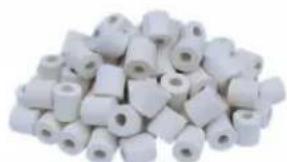
| Included Filter Media | Ceramic rings, filter sponge, biochemical cotton, bio balls |
| Material | Plastic |
| Protection Rating | IP44 |
| Special Features | Priming button, shut-off valve, drip loop recommendation |
| Maintenance | Clean O-rings, hoses, and filter media regularly; replace impeller if damaged |
| Safety | Use grounded outlet; disconnect before cleaning; do not run dry |
| Warranty | 2 years (void if unauthorized modification) |
Frequently Asked Questions - HW-404A WilTec
User questions about HW-404A WilTec
0 question about this device. Answer the ones you know or ask your own.
Ask a new question about this device
Download the instructions for your Aquarium in PDF format for free! Find your manual HW-404A - WilTec and take your electronic device back in hand. On this page are published all the documents necessary for the use of your device. HW-404A by WilTec.
USER MANUAL HW-404A WilTec
natural_image
Two identical 3D-printed industrial equipment units with black and gray components, shown from different angles (no text or symbols visible)Read and follow the operating instructions and safety information before using for the first time.
Technical changes reserved!
Due to further developments, illustrations, functioning steps and technical data can differ insignificantly.
Updating the documentation
If you have suggestions for improvement or have found any irregularities please contact us.
The information contained in this document is subject to change without prior notice. No part of this document can be copied or duplicated in another form without the prior written consent of WilTec Wildanger Technik GmbH. The WilTec Wildanger Technik GmbH assumes no liability for any errors in this user manual or the connection diagram.
Although WilTec Wildanger Technik GmbH has made every effort to make sure that this user manual is complete, accurate and updated, errors cannot always be avoided. In the event of problems with this user manual please complete and send this form back to us.
FAX-notification (+++49 2403 55592-15),
from:
Name:
Firm:
Tel/Fax:
I would like to report the following mistakes:
Customer Service WilTec Wildanger Technik GmbH
e-mail: service@WilTec.info
Tel:++ +49 2403 55592-0
Introduction
Thank you for purchasing this quality product. To minimize the risk of injury by means of fire or electric shock we urge that our clients take some basic safety precautions when using this device. Please read the operation instructions carefully and make sure you have understood its content.
Always use a grounded power connection with the appropriate mains voltage. You can find the corresponding mains voltage on the type plate. If you have any doubts about the connection being grounded, have it checked by a qualified professional. Never use a faulty electric cable.
Do not inspect the electrical part of the pressure pond filter in a wet or damp environment or when you are wet yourself and protect it from direct sunlight. Install this device in a safe location so that nobody can step on the cable, fall over or damage it. Disconnect the power plug before cleaning it and use only a damp cloth for cleaning. Avoid using cleaning agents and make sure that no liquid enters the electrical part of the pump.
The electric part of the device contains no parts that can be inspected or serviced by the user. Leave the maintenance, adjustment and repair to qualified technical personnel. In case of unauthorised intervention the 2-year warranty is no longer valid! Keep these operation instructions safe.

Important Safeguards
220-240V AC, 50Hz, 15W/20W/50W IP44
Please read thoroughly before installation and operation
To guard against injury, basic safety precautions should be followed when handling the appliance, as the following included:
- The appliance is only for aquarium and indoor use.
-
To avoid possible electric shock, special care should be taken since water is employed in the use of this appliance. Do not attempt to repair it by yourself. Return the appliance to the authorized service facility for maintenance or discard it.
-
Make sure that your outlet voltage corresponds to the stated voltage on the rating label of the pumps.
-
If the appliance is submerged into the water, DON'T reach for it! Please cut the power supply FIRST and then fetch it.
-
Carefully examine the appliance after installation. It should not be plugged in if its electrical components are wet.
-
Do not operate any appliance with a damaged cord or plug, or in abnormal state. The supply cord of the appliance cannot be replaced. If the cord is damaged the appliance should be scrapped.
-
Make sure that the electrical cord loops form a "Drip Loop" below the electrical outlet. The use of a drip loop will help prevent any water leaks or splashes from running down the electrical cord into your outlet. Instead of any water getting into your outlet it will simply drip off the cord at the lowest point in the loop.
-
Close supervision is necessary when the appliance is used by or near children.
-
Always unplug the appliance when not in use, before putting on or taking off parts, and before cleaning.
-
Do not install or store the appliance where it is exposed to moisture or to temperatures below freezing.
-
Make sure the appliance is securely installed before operating it.
-
Read and observe all the instructions supplied with the appliance and on the appliance.
-
The pump must not be run dry.
-
Never use accessories which are not recommended by the appliance manufacturer. It may result in fire, electric shock and/or personal injury.
-
Use the appliance ONLY for domestic purposes and in the way indicated in these instructions and place it in a dry environment.
natural_image
Close-up of a mechanical device with numbered components and directional arrows indicating motion (no text or symbols)- You can then access your filter trays to be able to clean the filter media or add filter media. Repeat step one to refasten the filter head to the base of the filter.
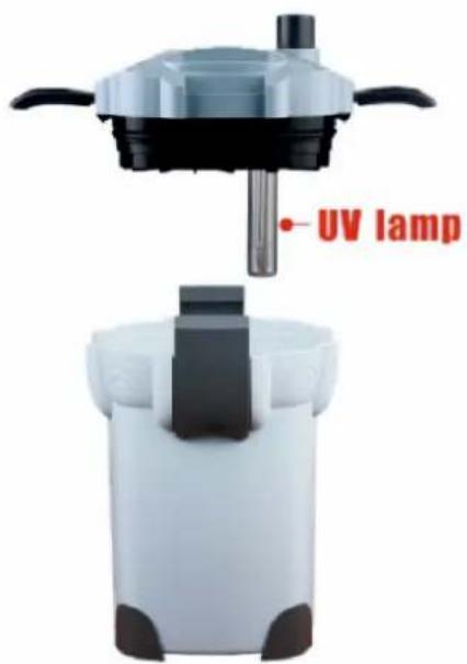
* UV-Unit depends on model
natural_image
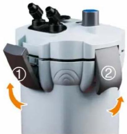
Close-up of hands using a handheld device to adjust a device with a magnified inset showing the close-up of its component (no text or symbols visible)- To set your filter up, the buckles (1) and (2) should be unclipped from the main body of the filter head this will then separate the head from the base of the filter.
-
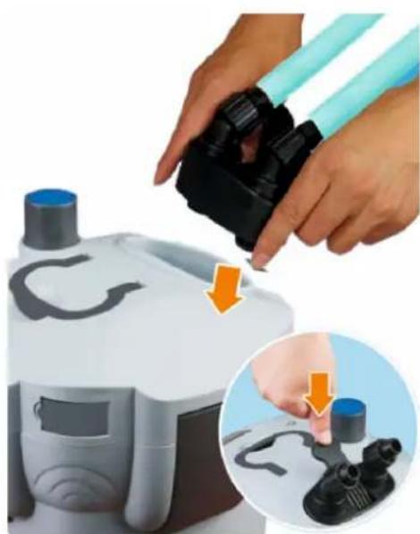
Push the inlet and outlet taps into the filter head and fasten using the small handle in between the taps this is also the shut of valve. After this attach your hose to each tap and secure using the screw caps.
-
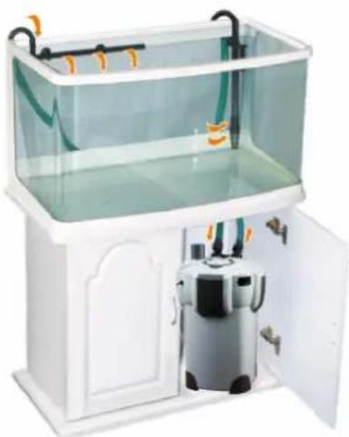
According to the diagramm then attach the input downpipes and output spraybars.
natural_image
White laboratory setup with a transparent rectangular tank and a small white device inside, no visible text or symbols.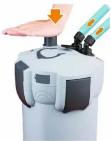
natural_image
Close-up of a robotic device with hand pressing down and two orange arrows indicating force or movement (no text or symbols)-
According to the diagramm then press down the blue primerbutton on top of the filter head this will prime the filter drawing water in through the hose. Repeat this if necessary until all pipework is full with water.
-
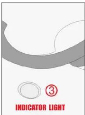
The switch to (3) turn your UV and indicator on and off is located in the side of the filter head. Please check the UV regularly when cleaning your filter to make sure it is in full working order.
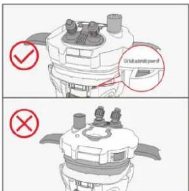
- At any condition, when the barrel is seperated by the cover, the protect switch will be off. Then the UV will be extinguish to avoid the damage to body.
The Method of replacing the UV light tube This applies only to UV-Unit models
natural_image
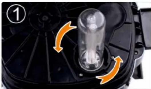
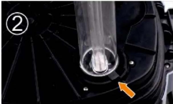
Close-up of a mechanical component with orange arrows indicating rotational or flow direction (no text or symbols)When the gap of the quartzhose tube and the gap of the connection of the light tubes are accordant, pull out the quartzhose tube.
- According to the diagrammatic presentation (1), please open the lid from the mail body carefully. Put the lid in inversion, then hold the quarzhose tube and circumgyrate it lightly, just as the picture shows.
natural_image
Close-up of a mechanical component with a transparent cylindrical tube and an orange arrow pointing to a feature (no text or symbols visible)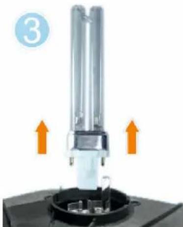
natural_image
Close-up of a mechanical device with two orange arrows indicating upward motion, no visible text or symbols.- According to the diagrammatic representation, pulling out the bad light tube. Installing the new light tube and the quartzhose tube.
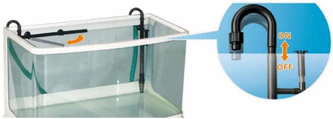
Assembly of water sampling and return lines
| Articel | Model | UVC | Output | Delivery Height | Weight | Cable | Dimensions | Baskets |
| 50197 | HW-302 | - 1000 l/h | 1,4 m | 3,5 kg | 1,8 m | 232x232x3 | 95 mm | 3 |
| 50195 | HW-303 | - 1400 l/h | 2,0 m | 5,0 kg | 1,8 m | 550x350x4 | 30mm | 3 |
| 50193 | HW-304 | - 2000 l/h | 2,5 m | 5,5 kg | 1,8 m | 610x390x4 | 70mm | 4 |
| 50196 | HW-402B | 9W | 1000 l/h | 1,4 m | 3,5 kg | 1,8 m | 660x500x4 | 3 |
| 50194 | HW-403B | 9W | 1400 l/h | 2,0m | 5,0 kg | 1,8 m | 550x350x4 | 3 |
| 50192 | HW-404B | 9W | 2000 l/h | 2,5 m | 6,0 kg | 1,8 m | 610x390x4 | 4 |
| 50359 | HW-404A | - 2000 l/h | 2,5 m | 4,5 kg | 1,8 m | 485x250x2 | 80mm | 4 |
| 50358 | HW-403A | - 1400 l/h | 2,0m | 4,5 kg | 1,8 m | 430x258x2 | 90mm | 3 |
| 58mm |
Filter management
| Problem Cause Solution | ||
| Pressing the inhale buckle (blue buckle), the filter has no re-sponse | The wrong joun of input and output bar | Join input and output bar again, the bar with dirtiness entrance is input bar |
| The motor is not Operating | The power is offThe shaft is brokenThe impeller is missing or the motor is clogged with foreign mate- materials such as pebbles and shells | Turn on the powerReplace the shaftDas Laufrad befestigen und Schmutz entfernenSet the impeller or clean out the drive system |
| Inhibited water flow (inhibited functioning) | Hose adapter unit is excessively dirtyHoses have been incorrectly connectedExcessive dirt build-up in the hosesFilter media is clogged | Detach the hose adaptor unit and clean the inside with a brushCheck whether the hose entangled or crimpedPeriodically clean the inside of the hoses and the intake and drainage pipesRemove the filter material and wash with tank water |
| Abnormal sound Emitted when starting the filter | Air is entering from the hose connection.Air is remaining in the filter case. | Please check if the hose connections are sealed (see also P.8)Leaving the power on, shake the unit to help remove remaining air. |
| Abnormal sound Emitted when Operating the filter | Dirty, displaced or distorted ORingsAir is remaining in the filter.Damaged impeller/drive magnet or spindle.Decrease ihre water flow die to water staining or dirt ors the impeller/drive magnet | Control all O-Rings, they have to be inserted in their place and fitted correctly; if necessary clean thoroughlyRemove and replace the plug ire the socket 3-4 times Gently shake the filter to remove remaining air.Replace parts (consult place of purchase)Set the impeller or clean out the drive system |
Further notes on care, cleaning, maintenance and solutions to possible problems see P.8.
Filter operation and problem solving
Noise reduction/ external air
Especially the suction intake /inlet and the connected suction surface must be checked for tightness and adjusted according to the water level of the aquarium. In case this is not possible due to aquarium technical reasons, seal the whole suction surface so that no external air can get into the filter.
De-aerating/ evacuating air
Take the return-flow hose that conducts the water from the filter to the tank and lead it into a clean bucket that is placed below the filter. Lead the hose into the bucket and carry out the dearation process (evacuate the air) by activating the manual pump. Please make sure that the possible maximal flow is adjusted to the inlet-outlet connector. As soon as no air bubbles can be seen, seal the hose with a finger und and install it again as intended on the return pipe at the top edge of the aquarium.
Leakage after installation or cleaning
In case of a slight leakage still persists after the installation or the cleaning of the filter, this indicates that the problem is most likely the sealing between the hose connector adaptor and the filter head (cover lid) The plug-in adaptor, to which the hoses are connected, has on the lower side two O-rings that must seal the connection inside the filter lid. If these O-Rings are dirty, displaced (out of place) or damaged they cannot seal properly anymore and water escapes in the filter lid/cover of the aquarium filter. The leak point is then the lowest point of the filter cover/lid and appears typically at the lateral clamping points that connect the cover lid with the filter tank/canister.
The remedy is here as simple as the failure itself. You have to rinse and check the O-rings. Make sure that the spots where the O-rings have to be inserted and positioned are free of dirt. On these particular spots algae formation can appear and impair or damage the O-rings' sealing if no regularly cleaning is carried out. This problem can also appear in case of a new installing because of sand, for instance.
Please allocate sufficient time for rinsing and cleaning; if this is not done carefully and thoroughly, it can happen that the aquarium canister filter still leaks after the O-ring sealings have been cleaned. If, despite a thorough cleaning the water leakage at the above-mentioned spots still persists, you must check the O-ring seating inside the adaptor. This requires opening the inlet/outlet adapter. Please contact our customer service.
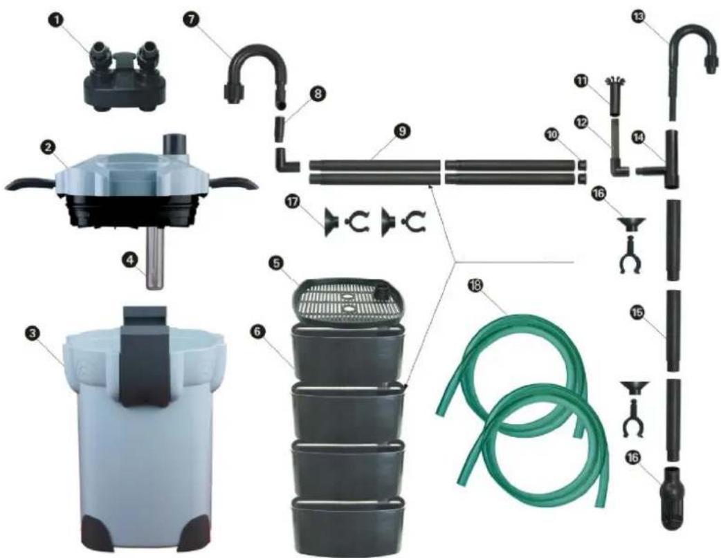
| 1 In & outlet connection 7 Outlet Curvy Bar 13 Input curvy bar | ||||
| 2 Filter Head 8 Connection bar | 14 Joint of dirtiness entrance | |||
| 3 Filter Canister 9 Spray bar 15 Input bar | ||||
| 4 UV Bulb 10 Spray bar cover | 16 Input cover | |||
| 5 Tray Cover | 11 | Dirtiness entrance | 17 Sucker | |
| 6 Filter Tray | 12 | Connected bar | 18 hoses | |
Filter Materials
natural_image
Pile of white cylindrical plastic components (no text or symbols visible)Ceramic Rings
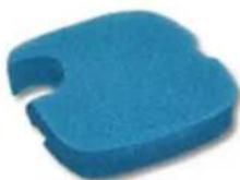
Filter Sponge
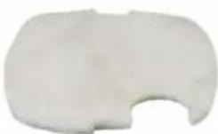
biochemical cotton
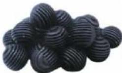
bio balls
Basics-Filter media
The delivered filter media represents only the basic filter material needed for your aquarium. Please inform yourself what filter materials are suitable for your aquarium because these can differ depending on the fish and plants living in your aquarium. Please use for only one stage of the filter one filter wadding (one piece). This should be regularly renewed because dirty fleece/wadding can quickly lead to a decrease in filter efficiency.
Aquarium external filters consist of several layers. The water (that is sucked) is filtered in several stages. The lowest layer (stage) consists of bio balls. These balls offer bacteria a large settling area and retain coarse dirt. Above it a layer with ceramic rings should follow. On the top level, we recommend a filter sponge covered with a filter wadding. (For example - please adjust)
Additionally you can place here another layer of activated carbon (in a netting bag or partly also as filter mat available) and this will form the one filter layer. This should not be permanent employed, but it should be used after a medication treatment and for turbid water with suspended particles. (Not included)
When you purchase a new aquarium filter or after it has been fully cleaned the useful bacteria must be enriched again. For this reason there are special bacteria cultures that can be supplied in the aquarium to facilitate their settlement.
It basically applies from bottom to top:
- Stage: mechanical/ partial biological filtering
- Stage: biological filtering
- Stage: chemical filtering (activated carbon, peat, phosphate etc.)
If necessary the aquarium filter can be extended to 4 stages by adding a mechanical or biological filter stage.
Disposal regulations
EU guidelines regarding the disposal of scrap electric appliances (WEEE, 2012/19/EU) were implemented in the law related to electrical and electronic equipment and appliances.
All WiITec electric devices that fall under the WEEE regulations are labelled with the crossed-out wheeled waste bin logo. This logo indicates that this electric equipment must not be disposed with the domestic waste.
The company WilTec Technik GmbH has been registered in the German registry EAR under the WEEE-registration number DE45283704.
Disposal of used electrical and electronic appliances (intended for use in the countries of the European Union and other European countries with a separate collection system for these appliances). The logo on the article or on its packaging points out that this article must not be treated as normal household waste but must be disposed to a recycling collection point for electronic and electrical waste equipment. By contributing to the correct disposal of this article you protect the environment and the health of your fellow men. Environment and health are threatened by inappropriate disposal.
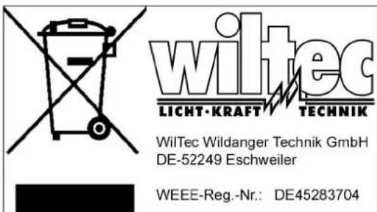
Materials' recycling helps reduce the consumption of raw materials.
Additional information on recycling this article can be provided by your local community, municipal waste disposal facilities or the store where you purchased the article.
Address:
The reprint or reproduction, even of excerpts, and any commercial use, even in part of this instructions manual require the written permission of WilTec Wildanger Technik GmbH.
Brand : WilTec
Model : HW-404A
Category : Aquarium