
HA-M-0.6.1 - Uncategorized ABB - Free user manual and instructions
Find the device manual for free HA-M-0.6.1 ABB in PDF.


| Product Type | Heating Actuator 6-gang (MDRC) |
| Brand | ABB |
| Model | HA-M-0.6.1 |
| Number of Channels | 6 |
| Power Supply | 24 V DC via free@home bus |
| Output Voltage | 24 to 230 V AC, 50/60 Hz |
| Nominal Current per Output | 160 mA resistive load at 45°C |
| Inrush Current per Output | Max 750 mA for 10 s |
| Protection | Short-circuit and overload protection (per group of 3 outputs) |
| Mounting | On 35 mm DIN rail (DIN EN 60715) |
| Dimensions (W x H x D) | 72 x 90 x 64.5 mm |
| Weight | 0.14 kg |
| Ambient Temperature (Operation) | -5°C to +45°C |
| Ambient Temperature (Storage) | -25°C to +55°C |
| Humidity | Max 93%, no condensation |
| Protection Type | IP20 |
| Protection Class | II |
| Insulation Category | Overvoltage category III, pollution degree 2 |
| Connection Terminals | Combi-head screw terminals (PZ1): 0.2-4.0 mm² fine-wire, 0.2-6.0 mm² single-wire |
| Bus Connection | Bus connection terminal (red/black) for free@home |
| Functions | Heating actuator, cooling actuator, heating/cooling actuator |
| Maintenance | Maintenance-free; clean with dry cloth only |
| Intended Use | Activation of valves via thermoelectric actuating drives for room temperature control |
| Safety | Installation only by qualified electricians; observe five safety rules and national regulations |
Frequently Asked Questions - HA-M-0.6.1 ABB
User questions about HA-M-0.6.1 ABB
0 question about this device. Answer the ones you know or ask your own.
Ask a new question about this device
Download the instructions for your Uncategorized in PDF format for free! Find your manual HA-M-0.6.1 - ABB and take your electronic device back in hand. On this page are published all the documents necessary for the use of your device. HA-M-0.6.1 by ABB.
USER MANUAL HA-M-0.6.1 ABB
flowchart
graph TD
    A["free@home"] --> B["lightbulb"]
    A --> C["document icon"]
    A --> D["print icon"]
    A --> E[" steam icon"]
    A --> F[" fan icon"]
natural_image
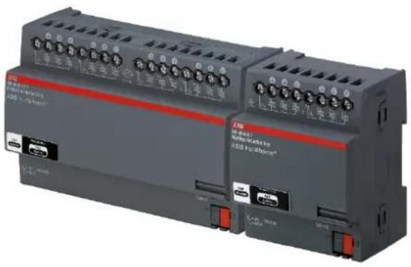
Exterior view of two industrial control modules with terminal labels (no readable text or symbols beyond branding)Heating Actuator
HA-M-0.6.1 (6254/0.6)
HA-M-0.12.1 (6254/0.12)
1 Notes on the instruction manual 3
2 Safety 4
2.1 Used symbols ____ 4
2.2 Intended use 5
2.3 Improper use 5
2.4 Target group / qualification of personnel 5
2.5 Liability and warranty 5
3 Environment 6
4 Product description 7
4.1 Scope of supply 7
4.2 Overview of types 7
4.3 Function overview 8
4.4 Description of functions 9
4.5 Device overview of 6gang heating actuator HA-M-0.6.1 13
4.6 Device overview of 12gang heating actuator HA-M-0.12.1 13
5 Technical data 14
5.1 Overview of HA-M-0.6.1 and HA-M-0.12.1 14
5.2 Dimensions 16
5.3 Connection diagram 17
6 Mounting 19
6.1 Safety instructions for mounting 19
6.2 Installation/mounting 21
6.3 Electrical connection 22
6.4 Dismantling 22
7 Commissioning 23
7.1 Allocation of devices and specifying channels 24
7.2 Setting options per channel 28
7.3 Linking 30
8 Updating options 31
9 Maintenance 32
9.1 Cleaning 32
1 Notes on the instruction manual
Please read this manual through carefully and adhere to the information contained therein. This will assist you in preventing damage to persons and property and ensure reliable operation and long service life of the device.
Please keep this manual in a safe place.
If you pass the device on, also include this manual.
If you require additional information or have questions about the device, please contact ABB STOTZ-KONTAKT GmbH or visit our Internet site at:
www.abb.com/freeathome
2 Safety
The device has been constructed according to the latest valid regulations governing technology and is operationally reliable. It has been tested and left the factory in a technically safe and reliable state.
However, residual hazards remain. Read and adhere to the safety instructions to prevent such hazards.
ABB STOTZ-KONTAKT GmbH accepts no liability for failure to observe the safety instructions.
2.1 Used symbols
The following symbols point to particular dangers involved in the use of the device and provide practical instructions.
Note
A notice indicates information or references to additional useful topics. This is not a signal word for a dangerous situation.
Examples
Examples for application, installation and programming
Important
This safety notice is used as soon as there is the danger of malfunction without the risk of damage to property or risk of injury.
Caution
This safety notice is used as soon as there is the danger of malfunction without the risk of damage to property or risk of injury.

Danger
This safety notice is used as soon as there is a threat to life and limb due to improper handling.

Danger
This safety notice is used as soon as there is a serious threat to life due to improper handling.
2.2 Intended use
The heating actuator must only be operated within the specified technical data.
The heating actuator is a rail mounting device for installing in distributors.
The heating actuator serves for the activation of valves via thermoelectric actuating drives for room temperature control.
The integrated bus coupler makes possible the connection to the free@home bus.
2.3 Improper use
The device is dangerous if used improperly. Any non-intended use is deemed improper use. The manufacturer is not liable for damages resulting from such improper use. The associated risk is borne exclusively by the user/operator.
The device must never be used outdoors or in bathroom areas. Do not push objects through the openings in the device.
The device has an integrated bus coupler. The use of an additional bus coupler is therefore not admissible.
2.4 Target group / qualification of personnel
Installation, commissioning and maintenance of the product must only be carried out by trained and properly qualified electrical installers. The electrical installer must have read and understood the manual and follow the instructions provided. The operator must adhere to the valid national regulations in his country governing the installation, functional test, repair and maintenance of electrical products.
2.5 Liability and warranty
Improper use, non-observance of this manual, the use of inadequately qualified personnel, as well as unauthorized modification excludes the liability of the manufacturer for the damages caused. It voids the warranty of the manufacturer.
3 Environment
Always dispose of the packaging material and electric devices and their components via the authorized collecting depots and disposal companies.
The products meet the legal requirements, in particular the laws governing electronic and electrical devices and the REACH ordinance.
(EU Directive 2006/96/EC, 2004/108/EC and 2011/65/EC RoHS)
(EU REACH ordinance and law for the implementation of the ordinance (EC) No.1907/2006)
4 Product description
The devices are heating actuators for installing on mounting rails. The devices have six or twelve channels and serve as actuators for the activation of heating systems via conventional thermal actuating drives.
Advantages:
» Six or twelve channels (depending on the type of device) for the activation of actuating drives.
Per channel, each device supports voltages of 24 V AC up to 230 V AC (this makes the use of all conventional thermal actuating drives possible).
» Three channels can be protected together by a circuit-breaker.
Note
Basic information about system integration is contained in the system manual. It is available for downloading at www.abb.com/freeathome.
4.1 Scope of supply
The scope of supply contains the heating actuator including bus terminal for coupling to the free@home bus.
4.2 Overview of types
| Type Product name | Actuator channels | Device | ||
| HA-M-0.6.1 | Heating actuator 6gang | 6 | 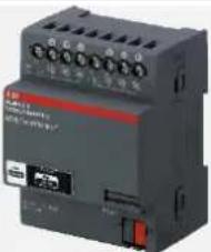 | |
| HA-M-0.12.1 | Heating actuator 12gang | 12 | 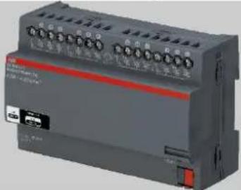 | |
Table 1: Overview of types
4.3 Function overview
The following table provides an overview of the possible functions and applications of the device:
| Icon in the operating surface | Information | |
 Heating Actuator Heating Actuator | Name: Heating actuatorFunction: For the activation of valves in heating circuits | |
 Cooling actuator Cooling actuator | Name: Cooling actuatorFunction: For the activation of valves in cooling circuits | |
 Actuator for heat... Actuator for heat... | Name: Actuator for heating and coolingFunction: For the activation of valves in circuits that are used for heating and cooling | |
Table 2: Function overview
4.4 Description of functions
The control of heating and cooling systems is illustrated in Fig. 1. The object of such control is the adjustment of the actual temperature to the desired set-point temperature in a room. The set-point temperature for the room can be set by means of a free@home room temperature controller. It also measures the actual temperature. Depending on the difference between both temperatures (control deviation) the room temperature controller creates a control value that is transmitted to the heating actuator (HA-M-0.6.1 or HA-M-0.12.1). The heating actuator, in dependence of the control value, controls one or several thermal actuating drives which set the valves in the heating or cooling circuit.

flowchart
graph LR
    A["Set-point temperature"] --> B["Controller"]
    B --> C["HA-M-0.6.1 HA-M-0.12.1"]
    C --> D["Thermal actuating drives"]
    D --> E["Heating"]
    E --> F["Actual temperature"]
    G["Room temp. controller free@home RTC-F-1"] --> B
    H["Control value free@home"] --> C
    I["Temperature sensor"] --> B
    J["Control element e.g. ABB TSA/K 230.1 e.g. ABB TSA/K 24.1"] --> D
Fig. 1: Diagram of heating control
4.4.1 Heating actuator, heating valves
This function is to be selected if only one heating system (e.g. floor heating, heaters, etc.) is to be controlled (no cooling). The channel of the heating actuator, which sets the valve in the pre-run of the heating circuit, is to be linked with the room temperature controller in menu "Linking" in the main menu of the System Access Point. The thermal actuating drive is to be connected hardware-related to this channel. Control and setting of the valve occurs automatically as soon as the room temperature controller has been connected to the heating actuator.

flowchart
graph LR
    A["Pre-run"] --> B["Valve"]
    B --> C["Heat"]
    C --> D["Return flow"]
Fig. 2: Valve in the pre-run of a heating circuit
4.4.2 Cooling actuator, valve for cooling
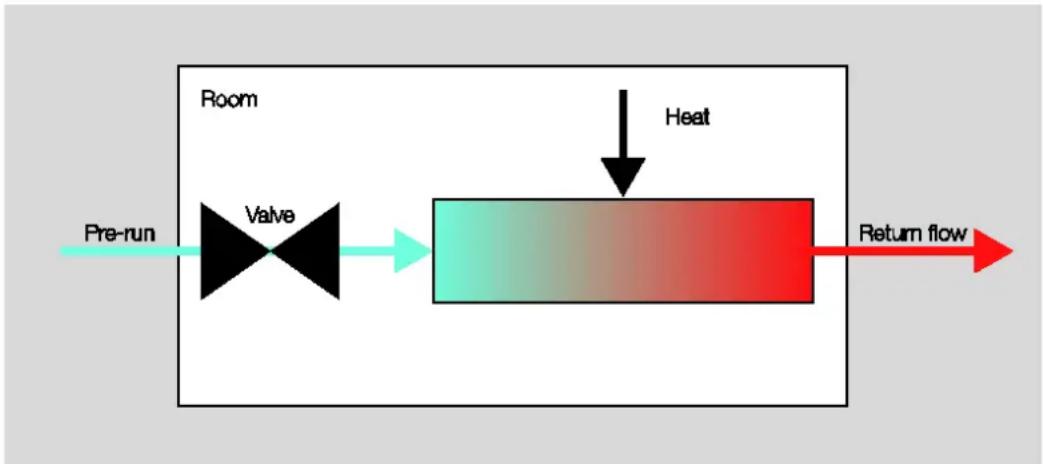
This function is to be selected if only one cooling system (e.g. cooling ceiling) is to be controlled. The channel of the heating actuator, which sets the valve in the pre-run of the cooling circuit, is to be linked with the room temperature controller in menu "Linking" in the main menu of the System Access Point. The thermal actuating drive is to be connected hardware-related to this channel. Control and position of the valve occurs automatically as soon as the room temperature controller has been connected to the heating actuator.
flowchart
graph LR
    A["Pre-run"] --> B["Valve"]
    B --> C["Heat"]
    C --> D["Return flow"]
Fig. 3: Valve in the pre-run of a cooling circuit
4.4.3 Actuator for heating and cooling, valve for heating and cooling
This function is to be selected if a heating system is used for which the same circuit, e.g. dependent on the season, is used for heating or cooling. The respective control for heating or cooling and the position of the valve occurs automatically as soon as the room temperature controller has been connected to the heating actuator. The selection of the control value for heating or cooling, for example, occurs by means of reversing a switch which is to be linked with the heating actuator via a binary input in menu "Linking" in the main menu of the System Access Point. As alternative, a binary output of the associated thermal system (if available) can be used.

flowchart
graph LR
    A["Pre-run"] --> B["Valve"]
    B --> C["Heat"]
    C --> D["Return flow"]
Fig. 4: Valve in the pre-run of a heating/cooling circuit
4.4.4 Control of several heating or cooling circuits
The control of several heating or cooling circuits becomes necessary, for example, for the control of several heaters in a room. In this case each heater is to be equipped with a thermal actuating drive. The actuating drives are to be connected either to a single channel of the heating actuator (the maximum nominal current is to be taken into consideration) or to several channels. The channels are to be configured as "Valve for heating" in the parameter settings of the heating actuator in the System Access Point. In menu "Linking" in the main menu of the System Access Point the associated room temperature controller is to be linked with all channels to which the actuating drives have been connected. The control occurs automatically following the linking in menu "Linking".
The procedure is to be applied analogous for cooling systems with the difference that the respective channels must be configured as "Valve for cooling".
4.4.5 Controlling parallel heating and cooling circuits
If several thermal systems which have appropriate heating and cooling circuits are operated parallel to heating and cooling, a thermal actuating drive is to be used for each valve of a circuit of a system. The corresponding channels are, depending on the connected heating or cooling system, to be configured as "Valve for heating" or "Valve for cooling". In menu "Linking" in the main menu of the System Access Point the associated room temperature controller is to be linked with all channels to which the actuating drives have been connected. The controls for heating and cooling occur automatically in dependence of the difference between the set-point and actual temperature.
Example
A room has two heaters and a cooling ceiling. All three systems are equipped with their own thermal actuating drive. The thermal actuating drives are to be connected to the heating actuator and are each to be linked in menu "Linking" of the main menu of the System access Point with any three channels of the heating actuator. The two channels to which the heaters are to be connected are to be configured as "Valve for heating". The channel to which the cooling ceiling is connected is to be configured as "Valve for cooling". The three valves in turn are to be linked with the associated room temperature controller. The control and the position of the valves on the two heaters and the cooling ceiling occur automatically.
4.5 Device overview of 6gang heating actuator HA-M-0.6.1
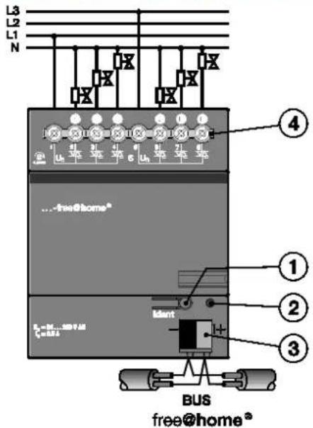
Fig. 5: Device overview of 6gang heating actuator
[1] Device identification during commissioning
[2] Identification LED
[3] Bus connection terminal
[4] Connecting terminals for thermal actuating drives
4.6 Device overview of 12gang heating actuator HA-M-0.12.1
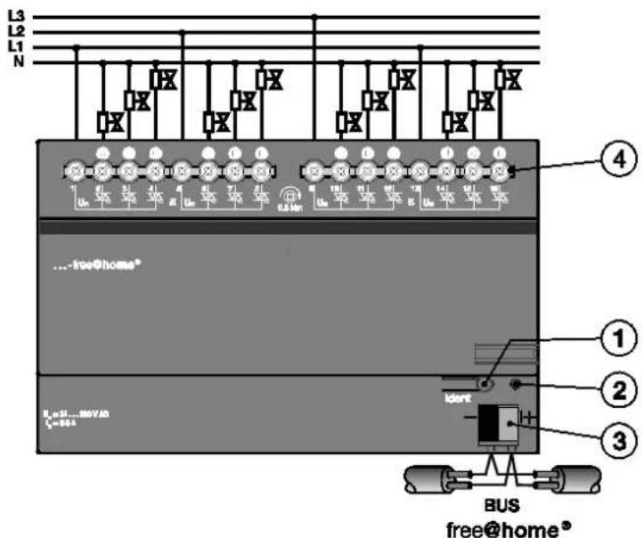
Fig. 6: Device overview of 12gang heating actuator
[1] Device identification during commissioning
[2] Identification LED
[3] Bus connection terminal
[4] Connecting terminals for thermal actuating drives
5 Technical data
5.1 Overview of HA-M-0.6.1 and HA-M-0.12.1
| Parameters Value | ||
| Power supply 24 V DC (via the bus) | ||
| Bus subscribers 1 (12 mA) | ||
| Connection (free@home) | Bus connection terminal: 0.4 - 0.8 mm | |
| Line type J-Y(St)Y, 2 x 2 x 0.8 mm | ||
| 6 or 12 semiconductor outputs | 3 non-floating outputs each in the groupProtected against short-circuit and overload | |
| Outputs | Rated voltage UN | 24 to 230 V AC50/60 Hz |
| Nominal current IN per output | 160 mA resistive load at Tu to 45°C | |
| Inrush current per output | Maximum 750 mA for 10 s at TU to 60°C | |
| CautionFor the parallel connection of actuating drives (e.g. TSA/K) the technical data of the respective actuating drive is to be observed! The inrush current (750 mA) and nominal current (160 mA) of the output must not be exceeded. | ||
| Connecting terminals | Combi-head screw-type terminal (PZ 1) | Connection cross section:0.2 - 4.0 mm2 fine-wire,2 x 0.2...2.5 mm20.2 - 6.0 mm2 single-wire,2 x 0.2...4.0 mm2 |
| Tightening torque 0.6 Nm | ||
| Operation -5°C to +45°C | ||
| Ambient temperature | Storage -25°C to +55°C | |
| Transport -25°C to +70°C | ||
| Environmental conditions | Maximum humidity | 93%, no dew permissible |
| Protection type | IP20 | Acc. to DIN EN 60 529 |
| Protection class | II | Acc. to DIN EN 61 140 |
| Insulation category | Over voltage category | III acc. to DIN EN 60 664-1 |
| Degree of contamination | 2 acc. to DIN EN 60 664-1 | |
| Mounting | On 35 mm mounting rail | Acc. to DIN EN 60 715 |
| Built-in position | Any | |
| Design | Rail mounting device (MDRC) | Modular installation device, Pro M |
| Installation width | 4 or 8 modules à 18 mm | |
| Installation depth 64.5 mm | ||
| Housing, colour | Plastic, basalt grey (RAL 7012) | |
| Dimensions | 72 x 90 x 64.5 mm (W x H x D)144 x 90 x 64.5 mm (W x H x D) | |
| Weight | 0.14 kg0.24 kg | |
| CE marking | According to EMC and low-voltage guidelines | |
Table 3: Technical data
5.2 Dimensions
| Note |
| All dimensions are in mm. |
Heating Actuator HA-M-0.6.1
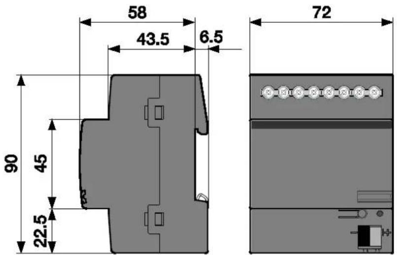
Fig. 7: Dimensions of 6gang heating actuator
Heating Actuator HA-M-0.12.1
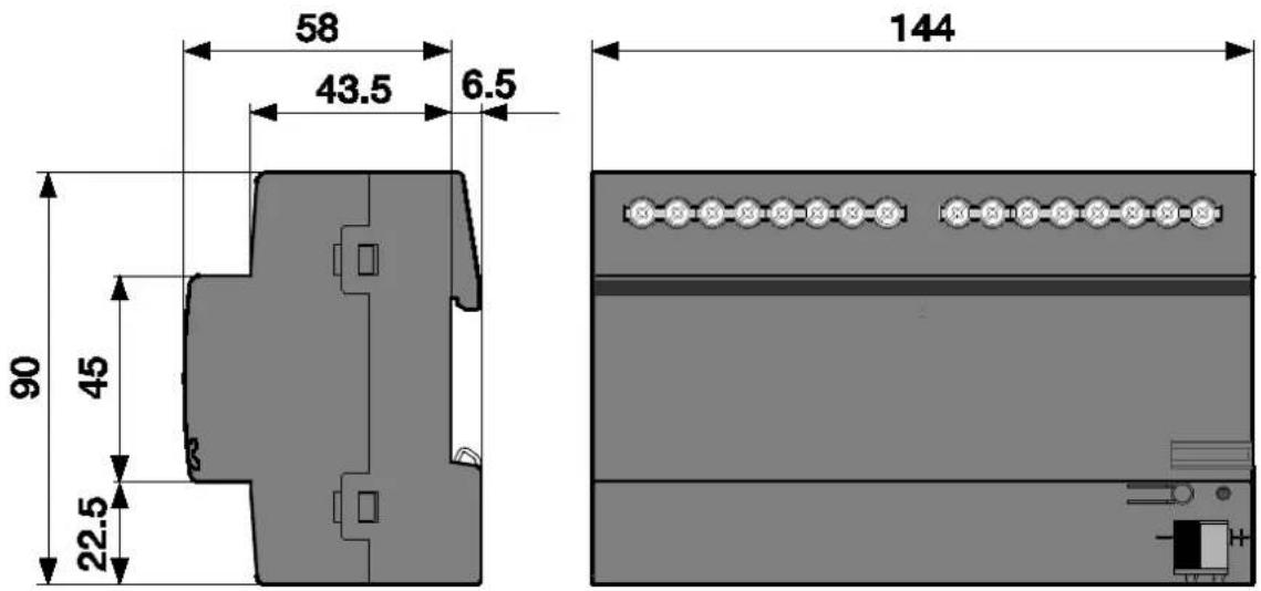
Fig. 8: Dimensions of 12gang heating actuator
5.3 Connection diagram
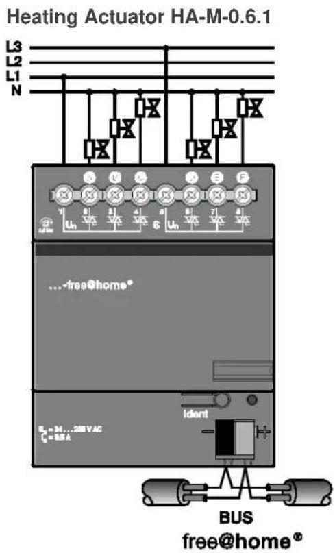
Fig. 9: Electrical connection of 6gang heating actuator

Fig. 10: Electrical connection of 12gang heating actuator
6 Mounting
6.1 Safety instructions for mounting

Danger
Risk of death due to electrical voltage
Dangerous currents flow through the body when coming into direct or indirect contact with live components. This results in electric shock, burns or even death.
Work improperly carried out on electrical systems is a hazard to one's own life and that of the user. Also fires and serious damage to property can result.
» Observe the relevant standards.
» Apply at least the "five safety rules" (DIN VDE 0105, EN 50 110):
- Disconnect
- Secure against being re-connected
- Ensure there is no voltage
- Connect to earth and short-circuit
- Cover or barricade adjacent live parts
Install the device only if you have the necessary electrical engineering knowledge and experience (see chapter 2.4).
» Use suitable personal protective clothing.
» Use suitable tools and measuring devices.
» Check the supply network type (TN system, IT system, TT system) to secure the following power supply conditions (classic connection to ground, protective earthing, necessary additional measures, etc.).
Danger
Risk of death due to short-circuit
Risk of death due to electrical voltage of 230 V during short-circuit in the low-voltage line.
» During mounting observe the spatial division (> 10 mm) of SELV electric circuits to other electric circuits.
» Observe the spatial division of SELV electric circuits and other electric circuits. Otherwise short-circuits can occur.
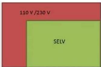
» If the minimum distance is insufficient, use electronic boxes or insulating tubes.
» Observe the correct polarity.
6.2 Installation/mounting
The device is a rail mounting device for installing in distributors for easy installation on 35 mm mounting rails according to DIN EN 60 715.
The device can be mounted in any position.
The stick-on label is to be removed and glued into the list (see system manual System Access Point).
The bus connection is established by means of the enclosed bus connection terminal.
The device is ready for operation after the bus voltage and, if required, an auxiliary voltage has been applied.
The description of the terminals is found on the housing.
Access to the device must be guaranteed for operation, testing, inspection, maintenance and repairs according to DIN VDE 0100-520.
Requirements for commissioning
A System Access Point is required to make the device operational. The device is ready when the bus voltage is applied.
6.3 Electrical connection
The electrical connection is made via screw terminals. The bus connection is established by means of the enclosed bus connection terminal. The terminal designation is located on the housing.
The bus line connection is established by means of the enclosed bus connection terminal (red/black).
» Three outputs each (A-C, D-F, etc.) are protected together and are supplied via one phase.
Several thermoelectric actuating drives can be connected in parallel to one output. When connecting several actuating drives in parallel it should ensure that the maximum inrush current or nominal current is not exceeded.
» The technical data of the actuating drives must be observed!
- The device is ready for operation after the bus voltage has been applied.
Mounting and commissioning must only be carried out by qualified electrical installers. When planning and setting up electrical systems and security-related systems for the detection of intrusion and of fires, the relevant standards, guidelines, rules and regulations of the respective country are to be observed.
» Protect the device against humidity, dirt and damage during transport, storage and operation!
» Operate the device only within the specified technical data!
» Operate the device only in a closed housing (distributor)!
» Prior to performing installation work the device is to be deactivated.

Danger
Danger to life
To prevent dangerous contact currents due to feedback from different external conductors, an all-pole deactivation is to be carried out when extending or changing the electric connection.
6.4 Dismantling
Dismantling is carried out in the reverse order.
7 Commissioning
Commissioning is always carried out via the Web-based surface of the System Access Point.
The System Access Point establishes the connection between the free@home participants and the smartphone, tablet or PC. It is used to identify and program the participants during commissioning.
Devices which are physically connected to the free@home bus, log themselves automatically into the System Access Point. They transmit information about their type and supported functions (see Table 2: Function overview, chapter 4.3).
During initial commissioning all devices are given a generic name (e.g. switch actuator 1, etc.). The user must change this name to a name practical for the system (Example: "Living room light" for an actuator in the living room.
Commissioning of the heating actuator is described in the following chapters. Here it is assumed that the basic commissioning steps of the overall system have already been carried out. General knowledge about the Web-based commissioning software of the System Access Point is assumed.
Note
General information about commissioning and parameterization is available in the system manual and the online Help of the "System Access Point" (www.abb.com/freeathome).
7.1 Allocation of devices and specifying channels
The devices connected to the system must be identified, i.e. they are allocated to a room according to their function and are given a descriptive name.

The allocation is made via the allocation function of the Web-based user interface of the System Access Point.
Device selection

Fig. 11: Allocating devices
In the "Add device" bar select the desired application and pull it via drag-and-drop onto the floor plan in the working area.
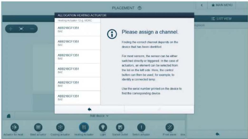
Fig. 12: Allocation
- A pop-up window opens automatically which lists all the devices suitable for the application selected.
The desired device can be identified in two ways.
Identification via serial number

Compare the short 3-digit number of the identification label with the numbers in the list and in this way identify the device you are searching for and, if necessary, also the channel.
Identification by pressing the "Identification button"
» Press the identification button on the device which you wish to add.
- The desired device is faded in automatically.
» Select the desired channel.
Assigning a name
| ALLOCATION ACTUATOR FOR HEATING AND COOLING | ||
| Heating Actuator 12-g, MDRC | Switch actuator | |
| ABB218CF1351BAE | Floor | Floor 01 |
| Room | Livingroom | |
| ABB218CF1351BAE | Name | Heating Actuator 12-g, MDRC |
| ABB218CF1351BAE | Serial number | ABB218CF1351 |
| Short ID | BAE | |
| ABB218CF1351BAE | Switch actuator |  |
| ABB218CF1351BAE | Name | eating livingroom |
| ABB218CF1351BAE | ||
Fig. 14: Assigning a name
» Enter a name that is easy to understand and under which the application is to be displayed later (e.g. "Living room heating").
» Press the tick at the bottom right to take over the entry.
7.2 Setting options per channel
General settings and parameter settings can be made for each channel.

The settings are made via the allocation function of the Web-based user interface of the System Access Point.
Device selection

Fig. 15: Device selection
» Select the device icon in the floor plan of the working area view.
- All setting options for the respective channel are displayed in the list view.
The following settings are available.
7.2.1 Heating actuator settings
![Heating livingroom Heating livingroom Function Valve for heating and cooling Parameters Contact type currentless closed Valve setting during faults [%] - 14 + - 5](/content/2026/05/759056/images/7bfbbb481998bbaa2aecb2c8b025957cf12c2fc8c8bc2d95f521ef554faf2e04.jpg)
[1] Changing the name
[2] Deleting the channel via "X"
[3] Selection of function (see section 4.3)
[4] Selection of channel contact type
[5] Specifying the control value to be applied during a fault
7.3 Linking
The heating actuators created via the allocation function can now be linked with a second device (e.g. room temperature controller).

The linking in the list view is then made via the linking function of the Web-based user interface of the System Access Point.
Linking heating actuator and room temperature controller
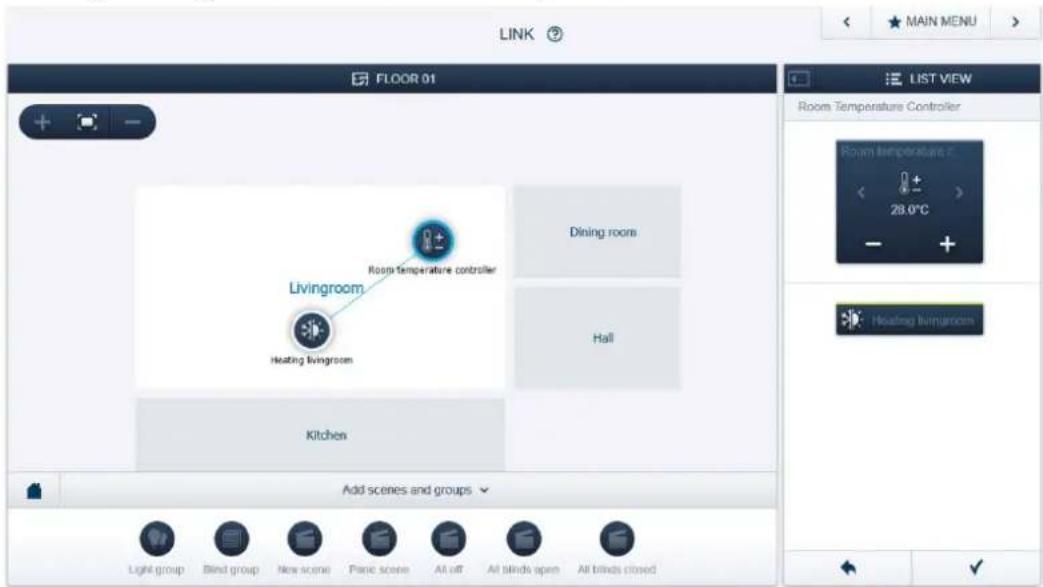
Fig. 16: Linking heating actuator and room temperature controller
To link a heating actuator with a room temperature controller insert the corresponding channels of the heating actuator and room temperature controller into the same room.
- The room temperature controller is automatically linked with all heating actuator channels added to this room.
Note
The links can be changed manually at all times.
8 Updating options
A firmware update is carried out via the Web-based user interface of the System Access Point. For this, visit the free@home website www.abb.com/freeathome.
9 Maintenance
The device is maintenance-free. In case of damage (e.g., during transport or storage), do not perform repairs. Once the device is opened, the warranty is void!
Access to the device must be guaranteed for operation, testing, inspection, maintenance and repairs (according to DIN VDE 0100-520).
9.1 Cleaning
Dirty devices can be cleaned with a dry cloth. If this is not sufficient, a cloth slightly moistened with a soap solution can be used. Caustic cleaning agents or solvents must not be used.
Further information and contact:
Note:
We reserve the right to make technical modifications to products as well as changes to the content of this document without prior notice. The respective agreed-upon conditions apply to orders. ABB accepts no responsibility for possible errors or incompleteness in this document.
We reserve all rights to this document and the topics and illustrations contained therein. Duplication, disclosure to third parties or the use of its contents - and of parts thereof - is forbidden without prior written approval from ABB AG.
Copyright© 2014 ABB
All rights reserved


- Notes on the instruction manual
- Safety
- Used symbols
- Note
- Examples
- Important
- Caution
- Danger
- Intended use
- Improper use
- Target group / qualification of personnel
- Liability and warranty
- Environment
- Product description
- Advantages:
- Scope of supply
- Overview of types
- Function overview
- Description of functions
- Heating actuator, heating valves
- Cooling actuator, valve for cooling
- Actuator for heating and cooling, valve for heating and cooling
- Control of several heating or cooling circuits
- Controlling parallel heating and cooling circuits
- Example
- Device overview of 6gang heating actuator HA-M-0.6.1
- Device overview of 12gang heating actuator HA-M-0.12.1
- Technical data
- Dimensions
- Connection diagram
- Mounting
- Safety instructions for mounting
- Risk of death due to electrical voltage
- Risk of death due to short-circuit
- Installation/mounting
- Requirements for commissioning
- Electrical connection
- Danger to life
- Dismantling
- Commissioning
- Allocation of devices and specifying channels
- Identification by pressing the "Identification button"
- Setting options per channel
- Heating actuator settings
- Linking
- Updating options
- Maintenance
- Cleaning
- Note:
Brand : ABB
Model : HA-M-0.6.1
Category : Uncategorized