
M652-ID3450 - Monitor MITSUBISHI - Free user manual and instructions
Find the device manual for free M652-ID3450 MITSUBISHI in PDF.


| Product type | LCD Monitor |
| Screen size | 64.5" (1639 mm diagonal) |
| Panel type | VA |
| Resolution | 1920 x 1080 (Full HD) |
| Brightness (typical) | 700 cd/m² |
| Contrast ratio | 4000:1 |
| Viewing angle | 178° both axes (CR≥10) |
| Response time | 8 ms (Gray to Gray) |
| Dimensions (without stand) | 1498 mm x 873 mm x 139 mm (59.0" x 34.4" x 5.5") |
| Weight (without stand) | Approximately 46.5 kg (102.5 lbs) |
| Power consumption | 458 W (445 W without speaker) |
| Power input | AC 100-240 V, 50/60 Hz, 4.9 A - 2.0 A |
| Power saving mode | Sleep: <2 W; Off: <1 W; Main switch off: 0 W |
| Input connectors | HDMI, DVI-D, DisplayPort, D-SUB, BNC, S-Video, Composite, Component, CAT5 |
| Output connectors | D-SUB, BNC, CAT5, RS-232C, LAN |
| Special features | 6-axis color adjustment, tiling up to 5x5, PIP/POP/Side-by-side, CAT5 long-distance transmission (up to 150 m), programmable scheduling, ambient light sensor, screen saver functions |
| Audio | 7 W + 7 W external speaker output |
| Remote control | Wireless remote with full function |
| Maintenance | Clean with lint-free cloth; do not use cleaning solutions or glass cleaner |
| Safety | Do not remove back cover; use approved power cord; avoid water and heat sources |
| Spare parts / Accessories | CAT5 Tx BOX, wireless remote, power cord, video cables, clamps, optional external speakers |
| Regulatory compliance | FCC Class B, CE, UL, C-UL, RoHS |
Frequently Asked Questions - M652-ID3450 MITSUBISHI
User questions about M652-ID3450 MITSUBISHI
0 question about this device. Answer the ones you know or ask your own.
Ask a new question about this device
Download the instructions for your Monitor in PDF format for free! Find your manual M652-ID3450 - MITSUBISHI and take your electronic device back in hand. On this page are published all the documents necessary for the use of your device. M652-ID3450 by MITSUBISHI.
USER MANUAL M652-ID3450 MITSUBISHI
natural_image
Illustration of a flat-screen monitor with a blank screen (no text or symbols)Before use
- Please be sure to read the "Safety Precautions." They are important to use this LCD display monitor.
- Please check the content of the package. This document contains instructions for World Wide model and Japan model, but their accessories are different.
ご使用の前に
Features ...... English-2
Important Information .... English-3
Declaration .... English-5
Safety Precautions, Maintenance & Recommended Use ...... English-6
Contents ...... English-7
Parts Name and Functions.... English-8
Buttons, Switch, and Indicator .... English-8
Connectors and Terminals .... English-9
Wireless Remote Control ....English-10
How to Use the Wireless Remote Control .... English-11
CAT5 Tx BOX .... English-12
Preparation for use ...... English-13
Flow of preparation .... English-13
[P-1] Preparation for installation .... English-14
Determine the installation location .... English-14
Ventilation requirements for enclosure mounting ....English-14
[P-2] Installing the monitor .... English-15
Using the wall mount or ceiling mount .... English-15
Using the monitor without the bezel .... English-15
Installing in the portrait position .... English-16
[P-3] Installing the optional speakers .... English-17
[P-4] Connection procedure .... English-18
Wiring diagram ...... English-18
Prevention of disconnection of HDMI cable ...... English-18
Connecting with a computer (analog connection) ...... English-19
Connecting with a computer (digital connection) ...... English-20
Connecting a video device (component video/HDMI device) ...... English-21
Connecting a video device (composite video/S video device)/stereo amplifier .... English-22
[P-5] Connecting CAT5 .... English-23
CAT5 for long-distance connection or multiple-monitor connection.... English-23
[P-6] Connecting RS-232C ...... English-25
Monitor control via RS-232C .... English-25
[P-7] Connecting LAN .... English-26
Monitor connection using LAN .... English-26
[P-8] Connecting the power cord to the monitor .... English-27
Connecting the power source ....English-27
How to Use .... English-28
Flow of How to Using .... English-28
[U-1] Turning on all the connected devices .... English-29
Turning on external devices English-29
Turning on the monitor .... English-29
Power Management Function ...... English-29
[U-2] Selecting the video input .... English-30
[U-3] Controlling the external devices .... English-31
[U-4] Selecting the OSD language .... English-31
[U-5] Auto-setup ...... English-32
[U-6] Selecting the picture mode .... English-32
[U-7] Screen adjustment .... English-33
[U-8] Picture adjustment .... English-33
[U-9] Volume control ...... English-34
[U-10] Schedule setting .... English-34
How to set up schedule .... English-35
[U-11] Remote control .... English-36
RS-232C/RS-485 Remote control .... English-36
LAN Remote control ...... English-38
Configuration and basic operation of OSD screen ....English-39
Configuration of OSD screen .... English-39
Basic operation of OSD .... English-40
OSD screen functions .... English-41
Other functions ...... English-51
Picture size .... English-51
Picture mode .... English-51
Audio input change ....English-51
OSD information ...... English-51
Control Lock mode .... English-51
Supplemental information of the auto brightness function ...... English-52
PIP, POP function ...... English-53
Remote control numbering function .... English-54
Troubleshooting English-55
Specifications English-56
Pin Assignment .... English-57
Engineered Specially for Public Display Use with High Durability and High-level Specifications
Panel Designed for Heavy Use
Highly durable LCD panel for commercial use.
Able to keep displaying crisp, vivid images and endures harsh environments of various public places such as airports and stations.
High Brightness, High Contrast
High brightness of 700 cd/m ^2 and high contrast ratio of 4000:1. Offers brightness as high as 700 cd/m ^2 for easy viewing in well-lit public places. A high contrast ratio of 4000:1 delivers sharp images with clear black and white colors, allowing viewers to read displayed information even from a distance.
Enhanced Display Functionality for Various Commercial Use/Support for System Confi guration Suitable for Diversifi ed Applications
6-axis Color Adjustment Function
6-axis color adjustment function for adjusting specific colors only.
You can adjust total six colors of red, green, blue and three medium colors independently to reproduce skin tones and colors of company or brand logos accurately in signage applications.
Digital Zoom
Zoom mode for expanding 4:3 image to 16:9.
Various zoom modes are provided and it is possible to expand 4:3 aspect ratio images to 16:9. In addition, you can select the dynamic display mode to display naturally widened images with different zooming rates around the screen center and screen edges. You can also optimally change the image size diagonally, horizontally, and vertically.
Tiling Capability with Frame compensation
49
Up to 25 panels (5 wide x 5 high) can be combined to create a single large image (i.e., video wall) or other high-impact signage. A frame compensation function is incorporated to compensate the width of panel bezels so that images are displayed with the utmost accuracy.
PiP, PoP and Side-by-side
45, and 53
Picture-in-Picture and Picture-out-of-Picture are available when you want to display video content from a video input source in the sub picture and display the PC input source in the main picture, and vice versa.
The native resolution as high as 1920 x 1080 can display these two input sources in the Side-by-side mode, ideal for broadcasting and video-conferencing applications.
Equipped with CAT5 Analog Signal Transmission Function/Supports Max. 150-meter Cable
CAT5 Video Connection
Transmitting analog video signal and control signal over a single CAT5 cable.
You can transmit analog RGB video signal and display control signal over a single CAT5 cable. Long-distance transmission up to 150 meters allows fl exible installation of the monitors and the personal computer.
Daisy-chain Connection (CAT5)
Linking up to 5 monitors.
You can connect up to 5 monitors in a daisy-chain configuration using CAT5 cable (max. 200 meters). The monitors can be installed away from each other depending on the usage.
Variable Management Functions Supporting Efficient Operation and Management
Programmable Scheduling Function
Pages 34, 35, and 48
The monitor's operating schedule can be programmed for up to seven different scheduled time intervals by time, day of the week and input port. This allows video content from different inputs to be displayed on certain monitors within the same installation according to the schedule, and extends the monitor's life and saves the power by turning it off during those hours or days it is not in use.
Screen-saver Functions
Page 46
To reduce image persistence and maximize the panel life in demanding signage applications, this product is equipped with four screen-saver functions.
For installations employing numerous monitors, the power-on delay function can power up the monitors sequentially with delay between 2-50 seconds after the power is applied. Using this function can prevent inrush current problems and reduce the overall electrical load requirements when a single power supply is used.
Brightness Compensation by the Ambient Light Sensors for Enhanced Visibility and Lower Power Consumption
Ambient Light Sensors (Brightness sensors)
Pages 8 and 52
Automatic screen brightness adjustment for enhanced visibility and lower power consumption.
The ambient light sensors on the front and rear of the monitor detect not only the light reflected on the front but also that on the rear to automatically obtain optimum brightness. Besides, the monitor adjusts its screen brightness according to the brightness of the displayed images. The screen is always easy to view in spite of brightness variation in the daytime and nighttime.
Others
DisplayPort
Pages 9 and 20
DisplayPort-compliant terminal is provided.
The monitor is equipped with a terminal supporting DisplayPort, the digital interface standard. You can transmit video signals over a single cable of max. 15 meters long.
Speakers
Pages 9 and 17
Special optional speakers can be installed.
The monitor is equipped with 7 W + 7 W speaker output connectors, through which voice messages, etc. are output clearly.
Remote Control
Pages 10 and 11
Special wireless remote control supports major operations and settings.
The special wireless remote control is supplied for major controls such as power-on/off, video source switching, and various settings.
Closed Caption
Page 50
You can display captions.
When closed-caption video signals are input, you can select to display or hide the captions on the screen.
This monitor is compliant with EIA-608-A.
DECLARATION OF CONFORMITY
This device complies with Part 15 of FCC Rules. Operation is subject to the following two conditions. (1) This device may not cause harmful interference, and (2) this device must accept any interference received, including interference that may cause undesired operation.
U.S. Responsible Party: Mitsubishi Digital Electronics America, Inc.
| A | d | d | r | e | s | s | : | 9 | 3 | |
| l | r | v | i | n | e | , | C | |||
| Tel. | No.: | +1 | - | (949) | 465-6000 | |||||
| Type | of | Product: | Computer | Monitor | ||||||
| E | q | u | i | p | m | e | n | t | C | l |
| M | o | d | e | l | : | M | D | |||

We hereby declare that the equipment specified above conforms to the technical standards as specified in the FCC Rules.
Windows is a registered trademark of Microsoft Corporation.
HDMI, the HDMI logo, and High-Definition Multimedia Interface are trademarks or registered trademarks of HDMI Licensing LLC in the United States and other countries.
The DisplayPort Icon is a trademark of the Video Electronics Standards Association, registered in the U.S. and other countries.
All other brands and product names are trademarks or registered trademarks of their respective owners.
Canadian Department of Communications Compliance Statement
DOC: This Class B digital apparatus meets all requirements of the Canadian Interference-Causing Equipment Regulations.
C-UL: Bears the C-UL Mark and is in compliance with Canadian Safety Regulations according to CAN/CSA C22.2 No. 60950-1.
FCC Information
- Use the attached specified cables with this equipment so as not to interfere with radio and television reception.
(1) The power supply cord you use must have been approved by and comply with the safety standards of U.S.A.,
(2) Please use the supplied shielded video signal cable. Use of other cables and adapters may cause interference with radio and television reception.
- This equipment has been tested and found to comply with the limits for a Class B digital device, pursuant to part 15 of the FCC Rules. These limits are designed to provide reasonable protection against harmful interference in a residential installation. This equipment generates, uses, and can radiate radio frequency energy, and, if not installed and used in accordance with the instructions, may cause harmful interference to radio communications. However, there is no guarantee that interference will not occur in a particular installation. If this equipment does cause harmful interference to radio or television reception, which can be determined by turning the equipment off and on, the user is encouraged to try to correct the interference by one or more of the following measures:
• Reorient or relocate the receiving antenna.
- Increase the separation between the equipment and receiver.
- Connect the equipment into an outlet on a circuit different from that to which the receiver is connected.
- Consult your dealer or an experienced radio/TV technician for help.
- You are cautioned that changes or modifications not expressly approved by the party responsible for compliance could void your authority to operate the equipment.

WARNING

TO PREVENT FIRE OR SHOCK HAZARDS, DO NOT EXPOSE THIS UNIT TO RAIN OR MOISTURE. ALSO, DO NOT USE THIS UNIT'S POLARIZED PLUG WITH AN EXTENSION CORD RECEPTACLE OR OTHER OUTLETS UNLESS THE PRONGS CAN BE FULLY INSERTED.
REFRAIN FROM OPENING THE CABINET AS THERE ARE HIGH VOLTAGE COMPONENTS INSIDE. REFER SERVICING TO QUALIFIED SERVICE PERSONNEL.

CAUTION

CAUTION: TO REDUCE THE RISK OF ELECTRIC SHOCK, MAKE SURE POWER CORD IS UNPLUGGED FROM WALL SOCKET. TO FULLY DISENGAGE THE POWER TO THE UNIT, PLEASE DISCONNECT THE POWER CORD FROM THE AC OUTLET. DO NOT REMOVE COVER (OR BACK). NO USER SERVICEABLE PARTS INSIDE. REFER SERVICING TO QUALIFIED SERVICE PERSONNEL.

This symbol warns user that uninsulated voltage within the unit may have sufficient magnitude to cause electric shock. Therefore, it is dangerous to make any kind of contact with any part inside this unit.

This symbol alerts the user that important literature concerning the operation and maintenance of this unit has been included. Therefore, it should be read carefully in order to avoid any problems.
CAUTION

This LCD Monitor uses a lamp that contains mercury. Disposal of the lamp or the LCD Monitor with the lamp may be regulated due to environmental considerations. For disposal or recycling information, please contact your local authorities or the Electronic Industries Alliance: www.eiae.org. (For US only).
Declaration of the Manufacturer
We hereby certify that the color monitor MDT652S (BV013)
is in compliance with
Council Directive 2006/95/EC:
— EN 60950-1
Council Directive 2004/108/EC:
- EN 55022
— EN 61000-3-2
— EN 61000-3-3
- EN 55024
and marked with

Mitsubishi Electric Corporation
2-7-3, Marunouchi,
Chiyoda-Ku
Tokyo 100-8310, Japan
Warning
This is a Class A product. In a domestic environment this product may cause radio interference, in which case the user may be required to take adequate measures.
Declaration of the Manufacturer
Note: This symbol mark is for EU countries only.
This symbol mark is according to the directive 2002/96/EC Article 10 Information for users and
Annex IV, and/or to the directive 2006/66/EC Article 20 Information for end-users and Annex II.
Your MITSUBISHI ELECTRIC product is designed and manufactured with high quality materials and parts which can be recycled and/or reused.
This symbol means that electrical and electronic equipment, batteries and accumulators, at their end-of-life, should be disposed of separately from your household waste.
If a chemical symbol is printed beneath the symbol shown above, this chemical symbol means that the
battery or accumulator contains a heavy metal at a certain concentration. This will be indicated as follows:
Hg: mercury (0,0005%), Cd: cadmium (0,002%), Pb: lead (0,004%)
In the European Union there are separate collection systems for used electrical and electronic products, batteries and accumulators.
Please, dispose of this equipment, batteries and accumulators correctly at your local community waste collection/recycling centre.
Please, help us to conserve the environment we live in!
Safety Precautions, Maintenance & Recommended Use
FOR OPTIMUM PERFORMANCE, PLEASE NOTE THE FOLLOWING WHEN SETTING UP AND USING THE LCD COLOR MONITOR:
- DO NOT REMOVE MONITOR BACK COVER. There are no user serviceable parts inside and opening or removing covers may expose you to dangerous shock hazards or other risks.
Refer all servicing to qualified service personnel.
- Do not spill any liquids into the cabinet or use your monitor near water.
- Do not insert objects of any kind into the cabinet slots, as they may touch dangerous voltage points, which can be harmful or fatal or may cause electric shock, fire or equipment failure.
- Do not place any heavy objects on the power cord. Damage to the cord may cause shock or fire.
- Do not place this product on a sloping or unstable cart, stand or table, as the monitor may fall, causing serious damage to the monitor.
- When operating the LCD monitor with its AC 100-120 V power supply in North America, use a power supply cord provided with the monitor.
If a power cord is not supplied with this monitor, please contact your supplier.
- When operating the LCD monitor with its AC 220-240 V power supply in Europe, use a power supply cord provided with the monitor.
If a power cord is not supplied with this monitor, please contact your supplier.
- In UK, use a BS-approved power cord with molded plug having a black (10 A) fuse installed for use with this monitor.
- When operating the LCD Monitor with a 220-240 V AC power supply in Australia, use the power cord provided with the monitor.
If a power cord is not supplied with this equipment, please contact your supplier.
- For all other cases, use a power cord that matches the AC voltage of the power outlet and has been approved by and complies with the safety standard of your particular country.
- Do not place any objects onto the monitor and do not use the monitor outdoors.
- The inside of the fl uorescent tube located within the LCD monitor contains mercury. Please follow the bylaws or rules of your municipality to dispose of the tube properly.
- Do not bend power cord.
- Do not use monitor in high temperature, humid, dusty, or oily areas.
- If monitor or glass is broken, do not come in contact with the liquid crystal and handle with care.
- If the LCD monitor is damaged and the liquid crystal leaks out, do not inhale or swallow it.
- Allow adequate ventilation around the monitor, so that heat can properly dissipate. Do not block ventilated openings or place the monitor near a radiator or other heat sources.
Do not put anything on top of the monitor.
- The power cable connector is the primary means of detaching the system from the power supply. The monitor should be installed close to a power outlet, which is easily accessible.
- Handle with care when transporting. Save packaging for transporting.
- Please clean the holes of back cabinet to reject dirt and dust at least once a year because of set reliability.
- If using the cooling fan continuously, it's recommended to wipe holes a minimum of once a month.
- When installing the remote control batteries;
- Align the batteries according to the (+) and (-) indications inside the case.
- Align the (-) indication of the batteries first inside the case.

CAUTION:
Immediately unplug your monitor from the wall outlet and refer servicing to qualified service personnel under the following conditions:
- When the power supply cord or plug is damaged.
- If liquid has been spilled, or objects have fallen into the monitor.
- If the monitor has been exposed to rain or water.
- If the monitor has been dropped or the cabinet damaged.
- If the monitor does not operate normally by following operating instructions.
Recommend Use
CAUTION:
- For optimum performance, allow 20 minutes for warm-up.
- Rest your eyes periodically by focusing on an object at least 5 feet away. Blink often.
- Position the monitor at a 90° angle to windows and other light sources to minimize glare and reflections.
- Clean the LCD monitor surface with a lint-free, non-abrasive cloth. Avoid using any cleaning solution or glass cleaner!
- Adjust the monitor's brightness, contrast, and sharpness controls to enhance readability.
- Avoid displaying fixed patterns on the monitor for long periods of time to avoid image persistence (after image effects).
- Get regular eye checkups.
Ergonomics
To realize the maximum ergonomic benefits, we recommend the following:
- Use the preset Size and Position controls with standard signals.
- Use the preset Color Setting.
- Use non-interlaced signals.
- Do not use primary color blue on a dark background, as it is diffi cult to see and may produce eye fatigue due to insufficient contrast.
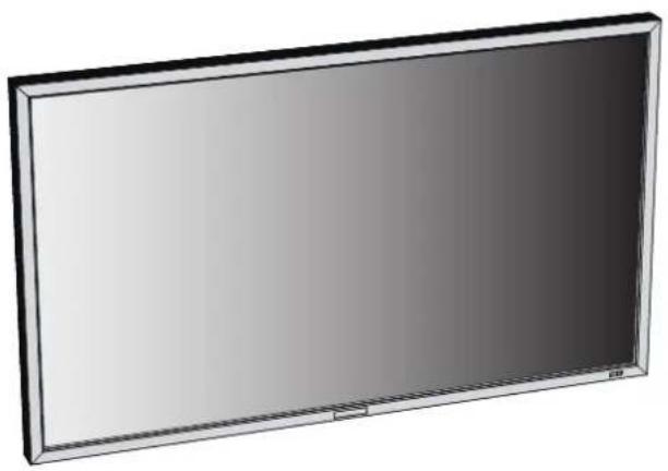
Your LCD monitor (MDT652S) comes with the following:
natural_image
3D rendering of a flat-screen monitor with a blank front panel (no text or symbols visible)□ LCD Monitor
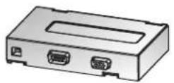
□ CAT5 Tx BOX
□ CD-ROM
* The supplied power cord varies depending on destination.
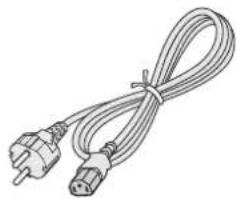
natural_image
Coiled electrical outlet cable with two terminal connectors (no text or symbols visible)□ Power Cord For EU
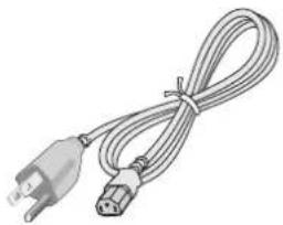
natural_image
Coiled cable with two connectors, one with a U-shaped tip and the other with a star-like connector (no text or symbols visible)□ Power Cord For North America
* For the use in the other regions, use a power cord that matches the AC voltage of the power outlet and has been approved by and complies with the safety standard of those regions or countries.
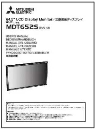
User's Manual
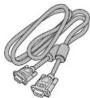
☐ Video Signal Cable (Mini D-SUB 15-pin to Mini D-SUB 15-pin Cable)
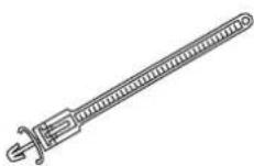
☐ Clamper x 2
(For preventing disconnection of the power cord and HDMI cable)
□ Clamper x 3
(For securing the cables)
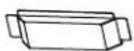
□ Protective cover
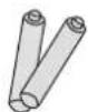
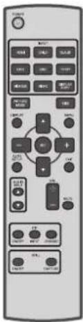
□ Wireless Remote Control and AAA Batteries
☐ Label to cover the UL certification marking
The following components are supplied as option.
- External Speakers
Buttons, Switch, and Indicator
Front
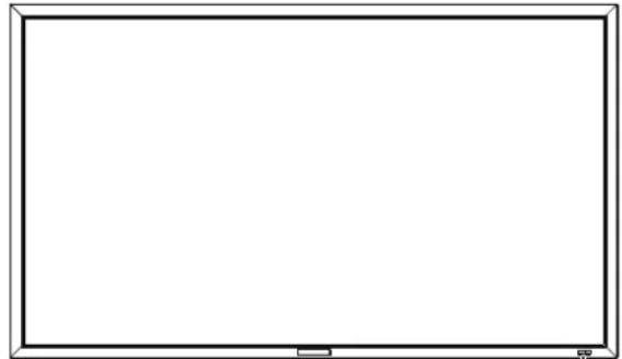
natural_image
Empty rectangular frame with no text, symbols, or markings211
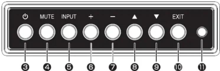
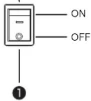
① Main Power Switch
Switches the main power on/off.
② Remote control sensor and Power indicator
Remote control sensor: Receives the signal from the wireless remote control.
Power indicator: Indicates the state of the LCD monitor.
- Steady green: The power is on.
• Steady red: The power is off.
Some operations such as power-on are possible.
- Steady green and red: The LCD monitor is in the sleep mode.
- Off: The main power is off.
- Steady red and blinking green: The LCD monitor is in the schedule standby mode.
- Blinking red: The LCD monitor has an error (detected by the self-diagnostic function).
③ POWER button ( ⏻)
Switches the power on/off.
This button doesn't work when the power indicator is off. Turn on the main power. (See page 29.)
④ MUTE button
Switches the audio mute on/off.
⑤ INPUT button
Displays the OSD menu to switch the video input.
You can select [RGB1], [RGB2], [RGB3], [RGB4], [RGB5], [RGB6], [DVD/HD], [VIDEO], or [VIDEO] using the UP ( ▲ ) or DOWN (▼ ) button.
⑥ PLUS (+) button
Acts as (+) button to increase the adjustment in the OSD menu. Increases the audio output level when the OSD menu is off.
⑦ MINUS (-) button
Acts as (-) button to decrease the adjustment in the OSD menu. Decreases the audio output level when the OSD menu is off.
⑧ UP (▲ button
Acts as ▲button to move the highlighted area up to select an adjustment item in the OSD menu.
⑨ DOWN (▼ button
Acts as ▼button to move the highlighted area down to select an adjustment item in the OSD menu.
⑩ EXIT button
Activates the OSD menu when the OSD menu is off.
Acts as EXIT button to go back to the previous OSD menu.
⑪ Brightness sensor (on the front and rear)
Sensor for the auto brightness function.
(Reference) Control Lock mode
You can lock the operation buttons. See page 51.
NOTE:
For details about the OSD menu operation using the buttons, see "Basic operation of OSD." (See page 40.)
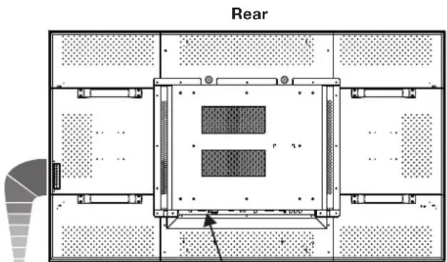
Connectors and Terminals
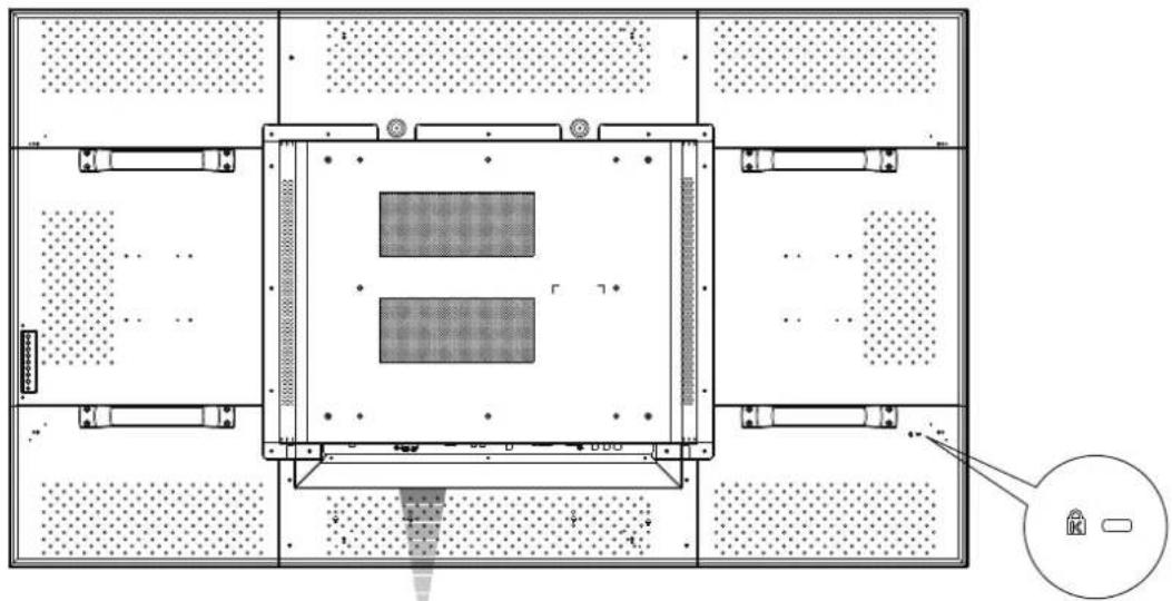
natural_image
Top-down schematic of a mechanical or electrical enclosure with labeled components and a magnified inset showing a device (no text or symbols present)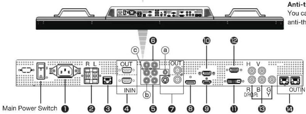
Anti-theft lock slot
You can insert a Kensington anti-theft lock key.
① AC IN (3-pin, with earth terminal)
Connects with the supplied power cord.
② EXTERNAL SPEAKER TERMINAL
Connects with the special stereo speakers (option).
③ LAN connector
Connects with a LAN cord.
④ RS-232C connector (D-SUB 9-pin)
IN connector:
Connects with the RS-232C OUT connector of a computer or other connected MDT652S.
OUT connector:
Connects with the RS-232C IN connector of other connected MDT652S.
⑤ AUDIO IN
Connects with the audio output connector of external equipment such as a computer, VCR, and DVD player.
(a) AUDIO1: ∅3.5 stereo mini-jack connector
(b) AUDIO2: RCA connector
(c) AUDIO3: RCA connector
⑥ AUDIO OUT (RCA)
Outputs the signal that is supplied to the selected AUDIO IN connector. Connects with an external audio amplifier, etc.
⑦ VIDEO INPUT/OUTPUT (BNC/S connector)
Connects with video equipment.
S VIDEO IN: S-video input connector (MINI DIN 4-pin)
VIDEO IN: BNC connector
VIDEO OUT: BNC connector
⑧ RGB6 IN (DisplayPort)
Connects with the digital video output of a computer, etc.
⑨ RGB1 IN (HDMI)
Connects with the digital video output of a computer, DVD player, etc.
⑩ RGB OUT (MINI D-SUB 15-pin)
Outputs the signal that is supplied to the RGB3, RGB4, or RGB5 IN connector.
⑪ RGB2 IN (DVI-D)
Connects with the digital video output of a computer, etc.
⑫ RGB3 IN (MINI D-SUB 15-pin)
Connects with the analog video output of a computer, etc.
13 RGB4 IN, DVD/HD IN (BNC)
Connects with the analog video output of a computer or the component video output of a DVD player, etc.
14 RGB5, CAT5 INPUT/OUTPUT (Modular connector 8-pin)
IN connector:
Connects with the CAT5 OUT connector of a CAT5 Tx BOX or other connected MDT652S.
OUT connector:
Connects with the CAT5 IN connector of other connected MDT652S.
Wireless Remote Control
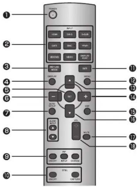
1 POWER button
Switches the power on/off.
* When the Power indicator is not glowing, no controls will work.
② INPUT buttons
Select the input signal from [RGB1] (HDMI), [RGB2] (DVI-D), [RGB3] (D-SUB), [RGB4] (BNC), [RGB5] (CAT5), [RGB6] (DISPLAY PORT), [DVD/HD] (YPbPr), [VIDEO], and [VIDEO].
③ PICTURE MODE button
Selects the picture mode from [HIGHBRIGHT], [STANDARD], [sRGB], and [CINEMA]. See page 32.
HIGHBRIGHT: The brightness is maximized.
STANDARD: Factory default setting.
sRGB: Suitable for color matching with sRGB-compliant devices.
CINEMA: Suitable for viewing movies.
④ DISPLAY button
Displays the screen information. See page 51. When the remote control mode is LOCK, you can set it back to NORMAL by holding down the DISPLAY button for at least 5 seconds (see page 49).
⑤ SET button
Accepts the settings made in the OSD menu.
⑥ MINUS button (-)
Acts as (-) button to decrease the adjustment in the OSD menu. When the PIP mode is active, this button moves the sub picture to the left.
⑦ AUTO SETUP button
Displays the auto setup menu. See pages 32 and 46.
⑧ AUDIO INPUT buttons
Select the audio input from [AUDIO1], [AUDIO2], [AUDIO3], and [HDMI]. However, note that [VIDEO] and [VIDEO] use common settings. You can select [HDMI] only when the video input source is [RGB1].
⑨ PIP (Picture-in-Picture) buttons
ON/OFF button: Switches the PIP or POP mode on/off. INPUT button: Selects video to be displayed in the sub picture.
CHANGE button: Changes the main picture with the sub picture.
[Description]
PIP: Picture-in-Picture
The sub picture is displayed within the main picture.
POP: Picture-out-Picture
The sub picture is displayed to the bottom right of the main picture.
SIDE BY SIDE
The main picture and the sub picture are displayed side by side.
NOTE:
When the screen size is [CUSTOM] or [REAL], the PIP and POP modes don't work.
10 STILL button
ON/OFF button: Switches the still picture mode on/off. CAPTURE button: Captures the new picture.
11 SIZE button
Selects the picture size from [FULL], [NORMAL], [CUSTOM], [DYNAMIC], and [REAL]. See page 51.
⑫ MENU button
Switches the OSD menu mode on/off.
⑬ UP button ()
Acts as ▲ button to move the highlighted area up to select an adjustment item in the OSD menu. When the PIP mode is active, this button moves the sub picture up.
14 PLUS button (+)
Acts as (+) button to increase the adjustment in the OSD menu. When the PIP mode is active, this button moves the sub picture to the right.
15 EXIT button
Displays the previous OSD menu.
16 DOWN button (▼)
Acts as ▼ button to move the highlighted area down to select an adjustment item in the OSD menu. When the PIP mode is active, this button moves the sub picture down.
17 MUTE button
Switches the mute function on/off.
18 VOLUME buttons (VOL)
Pressing the plus (+) side increases the audio output level. Pressing the minus (-) side decreases the audio output level.
How to Use the Wireless Remote Control
Operating Range of the Wireless Remote Control
Point the wireless remote control toward the LCD monitor's remote control sensor during button operation.
Use the wireless remote control within a distance of about 7 m from the front of the LCD monitor's remote control sensor and at a horizontal and vertical angle of within 30° within a distance of about 3.5 m.
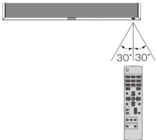
CAUTION:
The remote control system may not function when direct sunlight or strong illumination strikes the remote control sensor of the LCD monitor, or when there is an object in the path.
Handling the wireless remote control
* Do not subject to strong shock.
* Do not allow water or other liquid to splash on the wireless remote control. If the wireless remote control gets wet, wipe it dry immediately.
* Avoid exposure to heat and steam.
* Other than to install the batteries, do not open the wireless remote control.
Installing and removing the Wireless remote control batteries
The wireless remote control is powered by 1.5 V AAA batteries.
How to install the batteries
- Unlock and pull up the cover in the arrow's direction.
- Align the batteries according to the (+) and (-) indications inside the case.
- Replace the cover.
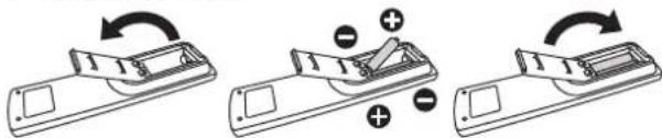
How to remove the batteries
- Unlock and pull up the cover in the arrow's direction.
- Remove the batteries.
CAUTION:
Incorrect use of batteries can result in leaks or explosion. Be careful especially about the following points.
- Place "AAA" batteries matching the (+) and (-) signs on each battery to the (+) and (-) signs of battery compartment.
- Do not mix battery types.
- Do not combine new batteries with used ones. It causes shorter battery life or leakage of batteries.
- Remove dead batteries immediately to prevent battery liquid from leaking into the battery compartment. Don't touch exposed battery acid because it causes damage to your skin.
NOTE:
If you do not use the wireless remote control for a long period, remove the batteries.
CAT5 Tx BOX
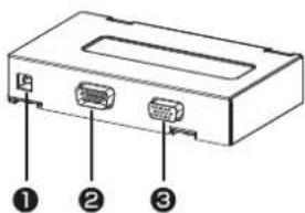
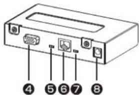
Front Rear
① USB (B type)
Connector for receiving the power supplied from the USB device such as the computer. By connecting a USB cable, you can control the CAT5 Tx BOX using the control commands transmitted over the USB cable.
CAUTION:
We have checked that the power is supplied and the control commands are transmitted properly via the USB connector by connecting it with our computers according to the USB standards.
When the CAT5 Tx BOX is combined with your computer system or USB hub system, check in advance that it operates properly.
② EXTERNAL CONTROL (D-SUB 9-pin)
When the communication via the USB connector is unusable, this connector can be used for RS-232C communication with the control device such as the computer.
NOTE:
RS-232C connection isn't necessary when the COM port number set by the USB driver is used. Make selection using the input select switch (USB/RS-232C) (7), as necessary.
③ RGB IN (MINI D-SUB 15-pin)
Connector for receiving the analog RGB video signal from the computer.
④ RGB OUT (MINI D-SUB 15-pin)
Video connector for buffering and outputting the analog RGB video signal received by the RGB IN connector ( ③).
⑤ Composite sync signal level switch
Switches the composite sync signal level. The TTL level and the 0.3 V level are switched.
⑥ CAT5 OUT (Modular connector 8-pin)
Connector for converting and outputting the video signal received by the RGB IN connector (③) and the control signal transmitted via the USB connector (①) or the RS-232C connector (②) to transmit them on the CAT5 cable.
CAUTION:
Never connect network devices to the CAT5 IN and OUT connectors. If you do so, they may adversely affect with each other, causing breakdown.
⑦ Input select switch (USB/RS-232C)
Switches the control input between the USB connector and the RS-232C connector.
⑧ Auxiliary power supply input connector (DC IN 5 V)
Though the power is supplied from the above-mentioned USB connector, an auxiliary DC power adapter (commercially available) is also available. When +5 V (according to the product specifications) is supplied from the above-mentioned DC power adapter, the power supply is automatically switched from the USB connector. (You cannot use both at the same time.)
CAUTION:
- Don't apply a voltage out of the specified range to the auxiliary power supply input connector or connect it with incorrect polarity. If you do so, the connected devices may be overheated or damaged.
- The auxiliary power supply input connector isn't intended for general use. Commercial DC power connectors are available in different shapes. When you want to use this connector, consult a qualified electrician or your dealer in advance.
Power connector type: DC jack R/A type (Diameter of the center pin: 2.0 mm)
| Pin Name Defi nition | ||||
| 1+5 | V DC Power source | |||
| 2 | G N | D | G N | D |
Flow of preparation
P-1
Preparation for installation
- Determine the installation location
- Ventilation requirements for enclosure mounting
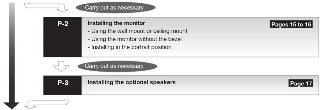
flowchart
graph TD
    A["Carry out as necessary"] --> B["P-2"]
    B --> C["Installing the monitor\n- Using the wall mount or ceiling mount\n- Using the monitor without the bezel\n- Installing in the portrait position"]
    B --> D["Pages 15 to 16"]
    E["Carry out as necessary"] --> F["P-3"]
    F --> G["Installing the optional speakers"]
    G --> H["Page 17"]
P-4
Connection procedure
- Wiring diagram
- Prevention of disconnection of HDMI cable
- Connecting with a computer (analog connection)
- Connecting with a computer (digital connection)
- Connecting a video device (component video/HDMI device)
- Connecting a video device (composite video/S video device)/stereo amplifi er
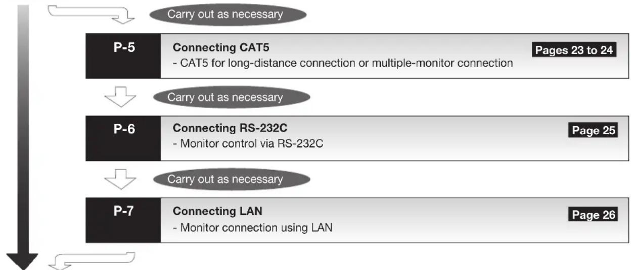
flowchart
graph TD
    A["P-5"] --> B["Connecting CAT5\n- CAT5 for long-distance connection or multiple-monitor connection"]
    C["P-6"] --> D["Connecting RS-232C\n- Monitor control via RS-232C"]
    E["P-7"] --> F["Connecting LAN\n- Monitor connection using LAN"]
    B --> G["Pages 23 to 24"]
    D --> H["Page 25"]
    F --> I["Page 26"]
    style A fill:#f9f,stroke:#333
    style C fill:#f9f,stroke:#333
    style E fill:#f9f,stroke:#333
    style B fill:#ccf,stroke:#333
    style D fill:#ccf,stroke:#333
    style F fill:#ccf,stroke:#333
P-8
Connecting the power cord to the monitor
- Connecting the power source
The monitor is ready for use.
P-1 Preparation for installation
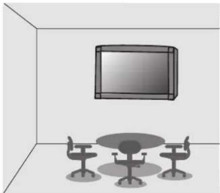
Install the monitor on a wall or ceiling strong enough to support its weight where the screen is easy to view, using commercially available wall or ceiling mount brackets.
natural_image
Interior view of a room with a TV and three chairs (no text or symbols visible)Determine the installation location
CAUTION:
DO NOT ATTEMPT TO INSTALL THE LCD MONITOR BY YOURSELF.
Installing your LCD monitor must be done by a qualified technician. Contact your dealer for more information.
CAUTION:
MOVING OR INSTALLING THE LCD MONITOR MUST BE DONE BY THREE OR MORE PEOPLE.
Failure to follow this caution may result in injury if the LCD monitor falls.
CAUTION:
Do not mount or operate the monitor upside down, face up, or face down.
IMPORTANT:
Lay the protective sheet, which was wrapped around the LCD monitor when it was packaged, beneath the LCD monitor so as not to scratch the panel.
Ventilation requirements for enclosure mounting
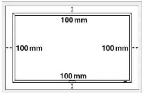
To allow heat to disperse, leave space around the monitor as shown in the figure below.
natural_image
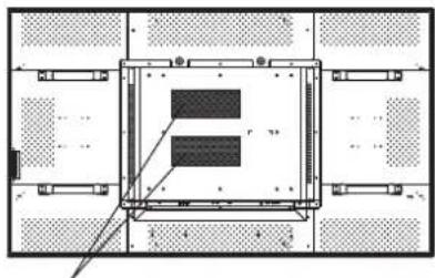
Technical diagram of a mechanical or electrical component with no visible text, numbers, or symbols.Don't block these holes.
CAUTION:
Don't block the holes in the rear of the monitor shown in the figure above. If they are blocked, heat accumulates inside the monitor, causing breakdown. The upper limit of the operation-guaranteed ambient temperature when the monitor is installed in the landscape position is 40^ . When installing the monitor in a case or an enclosure, ensure adequate ventilation to keep the temperature inside the case 40^ or lower by providing a cooling fan or ventilation holes in the case. The upper limit when the monitor is in the portrait position is 35^ .
This LCD has a temperature sensor and cooling fan. If the LCD becomes hot, the cooling fan will turn on automatically. If the LCD becomes overheated, the "Caution" menu will appear. If the "Caution" menu appears, stop using the monitor and allow it to cool. When the LCD monitor is used in an enclosure or with protection on LCD surface, please check the inside temperature of the monitor by "HEAT STATUS" (See page 50). If the temperature is higher than the normal level, set "COOLING FAN" to ON using the SCREEN SAVER function (See page 46).
Using the wall mount or ceiling mount
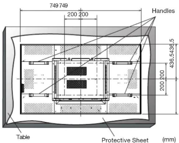
Lay the screen face down
Lay the protective sheet on a table, which was wrapped around the monitor when it was packaged, beneath the screen surface so as not to scratch the screen surface.
Failure to follow the correct mounting procedures can result in damage to the equipment or injury to the user or installer. Product warranty does not cover damage caused by improper installation.
Failure to follow these recommendations can void your warranty.
Use M8 screws (having a length 15 mm longer than the thickness of the mounting bracket) and tighten them securely. Prevent the screws from loosening using spring washers, etc. MITSUBISHI ELECTRIC recommends using mounting interface that comply with TÜV-GS and/or UL1678 standard in North America.
CAUTION:
For preventing the monitor from falling.
- Install the monitor with metal brackets for wall or ceiling installation (commercially available) on your own responsibility. For detailed procedures of installation, refer to the instructions of the metal brackets.
- To lessen the probability of injury and damage resulting from fall of the monitor in case of earthquake or other disaster, be sure to consult the bracket manufacturer for installation location.
- To lessen the risk of falling of the monitor, thread commercially available rope through the handles at the right and left of the monitor and secure the rope to the wall mount brackets or ceiling mount brackets.
- Do not sleep where the monitor may topple over or fall in case of an earthquake or other disaster.
- Use screws having enough strength to support the LCD display monitor (made of stainless steel etc.).
Using the monitor without the bezel
CAUTION:
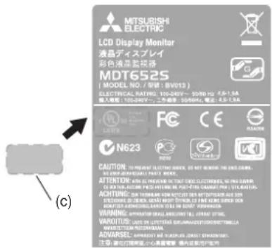
- MDT652S satisfi es the UL requirements as long as it is used with the bezel attached. When using the monitor without the bezel, in which case the monitor doesn't satisfy the UL requirements, cover the UL certifi cation marking on the rear panel with the supplied label.
-
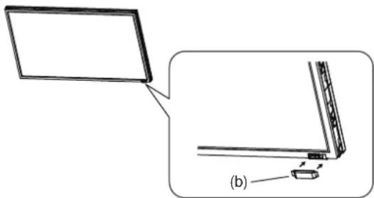
To prevent static damage to circuit boards, attach the protective cover to the LCD panel.
-
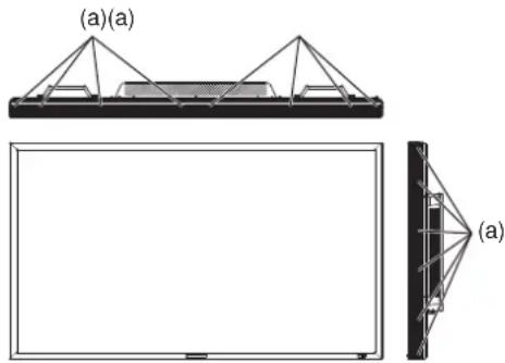
Unscrew the screws that hold the bezel to remove the bezel from the monitor.
natural_image
Technical diagram showing two views of a structural frame with triangular supports and a rectangular base, labeled (a) and (a)(a), without any text or symbols.(a): Screws for bezel
- Place the supplied protective cover (b) on the LCD panel using double-sided adhesive tape.
CAUTION:
Never touch the circuit boards because they may be damaged.
natural_image
Diagram showing a laptop screen and its side panel with a small component, labeled (b), without any text or symbols.- Cover the UL certification marking on the rear panel with the supplied label (c).
Installing in the portrait position
Conditions:
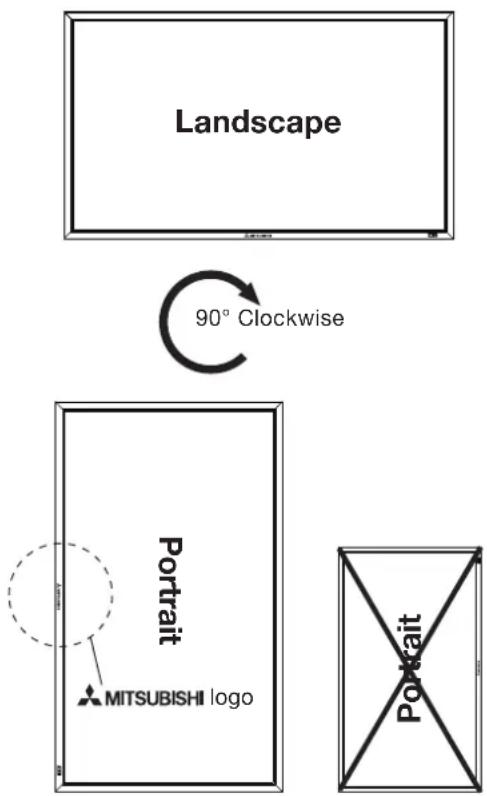
MDT652S can be installed in the portrait position, under the following conditions:
CAUTION:
Portrait position is available only when the monitor is wall-mounted or ceiling-mounted.
Operation Environment (Temperature) shall be limited, as shown below:
Operation Environment:
| Temperature | 5 - 35°C / 41 - 95°F |
| Humidity 20 - | 80% (without condensation) |
Place the monitor in the position shown below.
Do not place the monitor in landscape in any other manner than shown.
Optional speakers can not be attached when the LCD monitor is installed in the portrait position.
How to set-up
The “MITSUBISHI” logo should be on the LEFT side when viewed from the front of the monitor.
flowchart
graph TD
    A["Landscape"] -->|90° Clockwise| B["Portfolio Map"]
    B --> C["MITSUBISHI logo"]
    B --> D["Portfolio Map"]
    style A fill:#f9f,stroke:#333
    style B fill:#ccf,stroke:#333
    style C fill:#cfc,stroke:#333
    style D fill:#fcc,stroke:#333
P-3
Installing the optional speakers
Carry out as necessary
Before connecting the signal cable to PC and Video
- Optional speakers can be installed.
- Please refer to Quick Setup Guide of the optional speakers for the detailed installation procedure.
How to install the optional speakers
- Use the metal fittings and screws supplied with the optional speakers.
For the installation procedure, see the setup guide of the speakers. - Insert the left speaker cable into the SPEAKER (S) terminal (L) on the monitor, and insert the right speaker cable into the SPEAKER (S) terminal (R).
Left speaker Right speaker
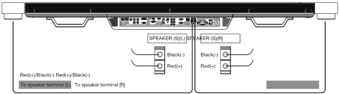
NOTE:
Match the polarity of the speaker cables and that of the terminals (+ (red)/- (black)).
Unmatched polarity may cause problems with audio output.
CAUTION:
Do not move the monitor with the speakers installed.
The monitor and the speakers may be damaged and you may be injured if the monitor falls.
P-4
Connection procedure
Before making connections
- First turn off the power of all the connected equipment before making connections.
• Refer to the user manual of each piece of equipment.
NOTE:
Please use the audio cable without resistance when the audio output terminal of the audio device and PC is stereo mini-Jack. When the audio cable with resistance is used, the audio level may not be increased or no audio may be output.
Wiring diagram
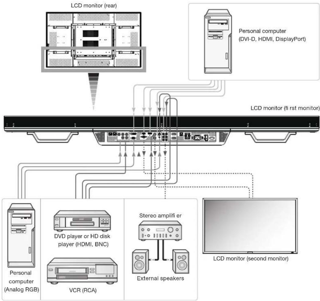
flowchart
graph TD
    A["LCD monitor (rear)"] --> B["Personal computer (DVI-D, HDMI, DisplayPort)"]
    B --> C["LCD monitor (fi rst monitor)"]
    C --> D["Personal computer (Analog RGB)"]
    C --> E["DVD player or HD disk player (HDMI, BNC)"]
    C --> F["VCR (RCA)"]
    C --> G["Stereo amplifi er"]
    G --> H["External speakers"]
    H --> I["LCD monitor (second monitor)"]
Prevention of disconnection of HDMI cable
When you connect the HDMI cable to the connector on the monitor, in order to prevent accidental disconnection of the cable, you are recommended to secure it using the supplied clamper as shown in the figure.
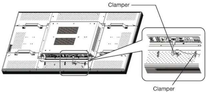
English-18
Connecting with a computer (analog connection)
Analog connection:
- Connection via RGB3 IN (D-SUB) connector
(1) Connect a signal cable (mini D-SUB 15-pin - mini D-SUB 15-pin) (accessory) to the RGB3 IN connector.
(2) Select [RGB3] using the INPUT button on the monitor or the D-SUB button on the wireless remote control.
- Connection via RGB4 IN (BNC: R•G•B•H•V, or R•G•B•Csync, RGB sync on green) connector
(1) Use a BNC cable (BNC x 5 - BNC x 5) (commercially available) to connect the BNC connector on the PC, and use a signal cable (mini D-SUB 15-pin - BNC x 5) (commercially available) to connect the mini D-SUB 15-pin connector on the PC.
(2) Select [RGB4] using the INPUT button on the monitor or the BNC button on the wireless remote control.
Second monitor connection:
- Connect the RGB OUT connector (mini D-SUB 15-pin) on the first monitor and the RGB3 IN connector (mini D-SUB 15-pin) on the second monitor using a signal cable (mini D-SUB 15-pin - mini D-SUB 15-pin) (an accessory of the second monitor or commercially available).
(The RGB3, RGB4, or RGB5 signal selected by the first monitor is output. The RGB1 or RGB2 signal isn't output.)
NOTE:
When different monitors need to be adjusted so that their tint can be identical, such as when using multiple screens, it is recommended to use a signal distributor (commercially available).
Audio connection:
- Connect an audio cable (ø3.5 mm stereo mini) (commercially available) to the AUDIO IN1 connector. Select [AUDIO1] using the AUDIO INPUT buttons on the wireless remote control.
• To output audio to the second monitor:
Connect the AUDIO OUT connector on the first monitor and the AUDIO IN2 connector or AUDIO IN3 connector on the second monitor using an audio cable (RCA) (commercially available).
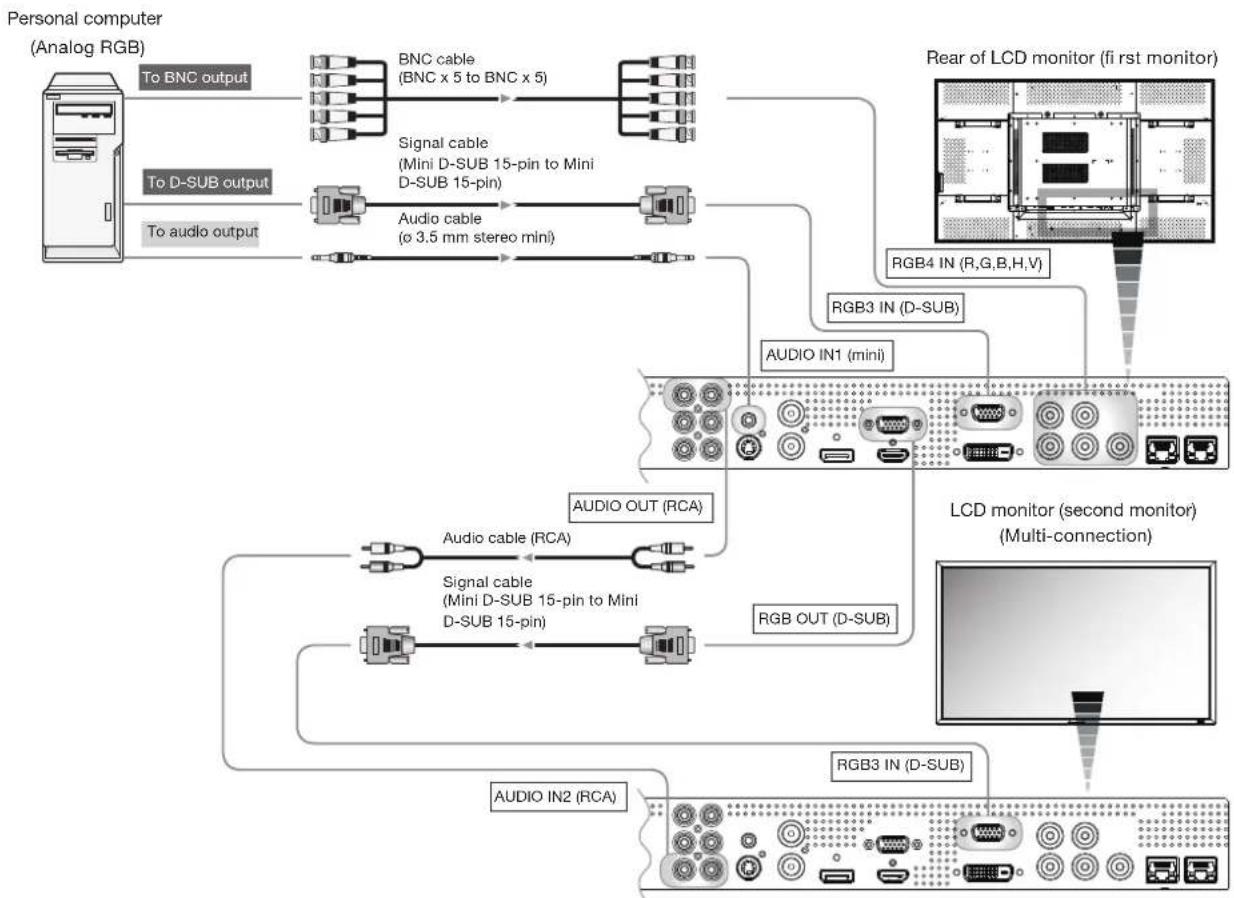
flowchart
graph TD
    A["Personal computer (Analog RGB)"] -->|To BNC output| B["BNC cable (BNC x 5 to BNC x 5)"]
    A -->|To D-SUB output| C["Signal cable (Mini D-SUB 15-pin to Mini D-SUB 15-pin)"]
    A -->|To audio output| D["Audio cable (c 3.5 mm stereo mini)"]
    B --> E["RGB4 IN (R,G,B,H,V)"]
    C --> F["RGB3 IN (D-SUB)"]
    D --> G["AUDIO IN1 (mini)"]
    G --> H["LCD monitor (second monitor) (Multi-connection)"]
    H --> I["RGB OUT (D-SUB)"]
    I --> J["RGB3 IN (D-SUB)"]
    J --> K["AUDIO OUT (RCA)"]
    K --> L["Audio cable (RCA)"]
    L --> M["Signal cable (Mini D-SUB 15-pin to Mini D-SUB 15-pin)"]
    M --> N["RGB OUT (D-SUB)"]
    N --> O["AUDIO IN2 (RCA)"]
The monitor automatically distinguishes the timings shown in the table below and sets the screen information. When a PC or other device is connected, it automatically displays images properly. See the page describing AUTO SETUP/AUTO ADJUST.
| Resolution | Frequency | Remarks Resolution | ition | Frequency | Remarks | |||||
| Horizontal Vertical | Horizontal Vertical | |||||||||
| 1 | 640 x 480 31.5 | kHz 60 Hz 6 | 1280 x 1024 | 64.0 kHz | 60 Hz | |||||
| 2 | 800 x 600 37.9 | kHz 60 Hz 7 | 1600 x 1200 | 75.0 kHz | 60 Hz | |||||
| 3 | 1024 x 768 | 48.4 kHz | 60 Hz | 8 | 1920 x 1080 | 67.5 kHz | 60 Hz | Recommend timing | ||
| 4 | 1280 x 768 | 47.8 kHz | 60 Hz | 9 | 1920 x 1200 | 74.0 kHz | 60 Hz | CVT Reduced Blanking | ||
| 5 | 1360 x 768 | 47.7 kHz | 60 Hz | |||||||
NOTE:
When a signal other than 1920x1080 is input, characters may be blurred and figures and objects may be distorted. Images may not be displayed correctly depending on the video card or driver being used.
Connecting with a computer (digital connection)
Digital connection:
- Connection via the RGB1 IN connector (HDMI)
(1) Connect an HDMI cable (commercially available) to the RGB1 IN connector.
(2) Select [RGB1] using the INPUT button on the monitor or the HDMI button on the wireless remote control.
- Connection via the RGB2 IN connector (DVI-D)
(1) Connect a DVI-D cable (commercially available) to the RGB2 IN connector.
(2) Select [RGB2] using the INPUT button on the monitor or the DVI-D button on the wireless remote control.
- Connection via the RGB6 IN connector (DisplayPort)
(1) Connect a DisplayPort cable (commercially available) to the RGB6 IN connector.
(2) Select [RGB6] using the INPUT button on the monitor or the DISPLAY PORT button on the wireless remote control.
Audio connection:
- Connect an audio cable (ø3.5 mm stereo mini) (commercially available) to the AUDIO IN1 connector.
Select [AUDIO1] using the AUDIO INPUT buttons on the wireless remote control.
When an HDMI cable is connected, select HDMI audio.
(You can select HDMI only when the video input is [RGB1].)
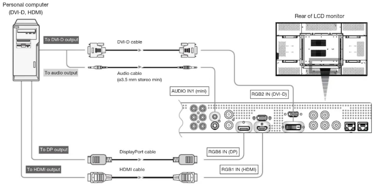
flowchart
graph TD
    A["Personal computer (DVI-D, HDMI)"] -->|To DVI-D output| B["DVI-D cable"]
    A -->|To audio output| C["Audio cable (ø3.5 mm stereo mini)"]
    A -->|To DP output| D["DisplayPort cable"]
    A -->|To HDMI output| E["HDMI cable"]
    B --> F["AUDIO IN1 (mini)"]
    C --> F
    D --> G["RGB6 IN (DP)"]
    E --> H["RGB1 IN (HDMI)"]
    F --> I["RGB2 IN (DVI-D)"]
    G --> I
    H --> I
    I --> J["Rear of LCD monitor"]
Connecting a video device (component video/HDMI device)
This monitor can be connected to a video device equipped with component output such as a DVD player.
Refer to the user's manual of the connected device for details. (Cables shown in the figure below are commercially available.)
- To connect a DVD player equipped with component output to the DVD/HD IN connector (YPbPr or YCbCr) on the monitor, use a BNC cable (BNC x 3 - BNC x 3) and a BNC - RCA adaptor (commercially available), or a signal cable (BNC x 3 - D connector). Select [DVD/HD] using the INPUT button on the monitor or the YPbPr button on the wireless remote control.
• To make audio connection, connect an audio cable (RCA) to the AUDIO IN2 connector or the AUDIO IN3 connector.
Select [AUDIO2] or [AUDIO3] using the AUDIO INPUT buttons on the wireless remote control.
- To connect a DVD player equipped with HDMI output to the RGB1 IN connector (HDMI) on the monitor, use an HDMI signal cable.
Select [RGB1] using the INPUT button on the monitor or the HDMI button on the wireless remote control.
- For HDMI cable connection, select HDMI audio.
(You can select HDMI audio only when the video input is [RGB1].)
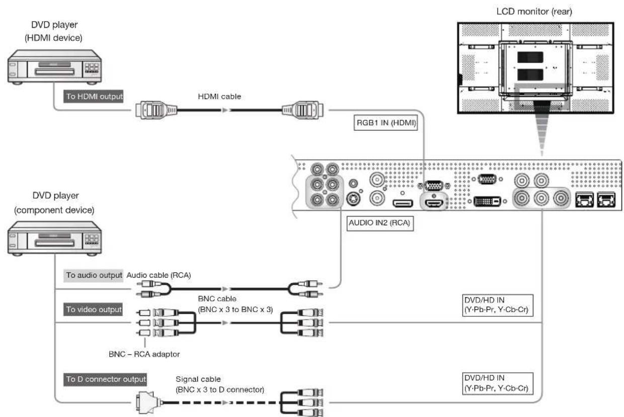
flowchart
graph TD
    A["DVD player (HDMI device)"] -->|To HDMI output| B["+"]
    B --> C["HDMI cable"]
    C --> D["RGB1 IN (HDMI)"]
    E["DVD player (component device)"] -->|To audio output| F["+"]
    F --> G["Audio cable (RCA)"]
    G --> H["BNC cable (BNC x 3 to BNC x 3)"]
    H --> I["BNC - RCA adaptor"]
    I --> J["Signal cable (BNC x 3 to D connector)"]
    J --> K["+"]
    L["LCD monitor (rear)"] --> M["+"]
    M --> N["AUDIO IN2 (RCA)"]
    N --> O["DVD/HD IN (Y-Pb-Pr, Y-Cb-Cr)"]
    O --> P["DVD/HD IN (Y-Pb-Pr, Y-Cb-Cr)"]
Connecting a video device (composite video/S video device)/stereo amplifi er
This monitor can be connected to a stereo amplifier.
Refer to the user's manual of the stereo amplifier for details. (Cables shown in the figure below are commercially available.)
- To connect a video device to the VIDEO IN connector (VIDEO IN or S-VIDEO IN) on the monitor, use a BNC cable or an S video cable. For connection to the audio input connector on the monitor, use an audio cable (RCA). Connect the connectors of the audio cable (RCA) correctly. For connection to the VIDEO IN connector, select [VIDEO] using the INPUT button on the monitor or the VIDEO button on the wireless remote control. For connection to the S-VIDEO IN connector, select [VIDEO
] using the INPUT button on the monitor or the VIDEO(S) button on the wireless remote control. - To connect two monitors, connect one end of a BNC cable to the VIDEO OUT connector of the first monitor and the other end to the VIDEO IN connector of the second monitor.
NOTE:
When different monitors need to be adjusted so that their tint can be identical, such as when using multiple screens, it is recommended to use a signal distributor (commercially available).
- When connecting a stereo amplifier to the monitor, be sure to turn off the power of the stereo amplifier. For connection to the audio output connector on the monitor, use an audio cable (RCA). Connect the connectors of the audio cable (RCA) correctly. Be sure to turn on the monitor first, and then turn on the stereo amplifier.
- The selected audio input signal is output from the AUDIO OUT connector.
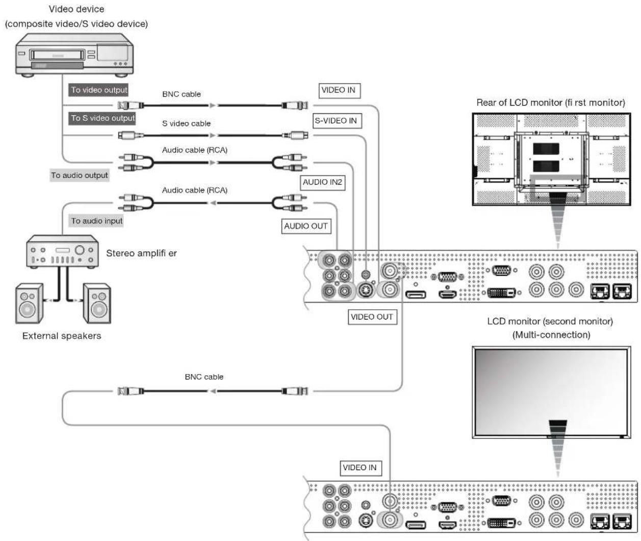
flowchart
graph TD
    A["External speakers"] --> B["To audio input"]
    A --> C["To audio output"]
    A --> D["To video output"]
    D --> E["BNC cable"]
    E --> F["Video IN"]
    D --> G["S video cable"]
    G --> H["Video OUT"]
    D --> I["Audio cable (RCA)"]
    I --> J["Audio IN2"]
    D --> K["Audio cable (RCA)"]
    K --> L["Audio OUT"]
    A --> M["Stereo amplifier er"]
    M --> N["BNC cable"]
    N --> O["LCD monitor (second monitor)<br>(Multi-connection)"]
    O --> P["Video OUT"]
    style A fill:#f9f,stroke:#333
    style B fill:#ccf,stroke:#333
    style C fill:#ccf,stroke:#333
    style D fill:#cfc,stroke:#333
    style E fill:#fcc,stroke:#333
    style F fill:#cff,stroke:#333
    style G fill:#cff,stroke:#333
    style H fill:#ffc,stroke:#333
    style I fill:#ffc,stroke:#333
    style J fill:#ffc,stroke:#333
    style K fill:#ffc,stroke:#333
    style L fill:#ffc,stroke:#333
    style M fill:#cfc,stroke:#333
    style N fill:#cfc,stroke:#333
    style O fill:#cfc,stroke:#333
    style P fill:#cfc,stroke:#333
CAT5 for long-distance connection or multiple-monitor connection
The CAT5 video connection function is for transmitting the analog RGB video signal of the computer and the control signal of the monitor over a long distance using CAT5 cables. The computer can control the monitor via the supplied CAT5 Tx BOX.
CAUTION:
Never connect network devices (such as a hub and a computer for LAN) to the CAT5 Tx BOX and the IN and OUT connectors of the monitor. If they are connected, the network devices themselves, CAT5 Tx BOX, and monitor may be damaged.
1. Installation of the USB driver for CAT5 serial communication control
To connect the computer and the CAT5 Tx BOX via USB interface, it is necessary to install the USB driver to the computer from the CD-ROM supplied with the monitor. (Installing the USB driver isn't necessary when the communication control isn't used or the RS-232C cable is used for connection.)
OS supported: Windows ^® XP, Windows Vista ^®
How to install:
1) Installation to Windows ^® XP
Start the "PL2303-Driver_XP2K_v *****.exe" file in the Windows XP folder on the CD-ROM supplied with the monitor and install the driver according to the instructions displayed on the screen.
2) Installation to Windows Vista ^®
Start the "PL2303_Prolifi c_Vista_*****exe" file in the Windows VISTA folder on the CD-ROM supplied with the monitor and install the driver according to the instructions displayed on the screen.
NOTE:
It is unnecessary to install the USB driver if you don't use the communication control or the USB driver. When the window asking you to install the driver is displayed, select cancel. As for the latest driver for the Windows operating system, check the operation of the interface IC "PL-2203" in advance, referring to the website of Prolifi c Technology Inc. Prolifi c Technology Inc. and Mitsubishi don't assume any responsibility or liability for any damages incurred by the user.
Operation check by Mitsubishi
- File name: PL2303_Prolifi c_DriverInstaller_v110.zip, Release date: December 2, 2009, Version: V1.1.0
Windows XP (32 bits): Operated Windows Vista (32 bits): Operated Windows 7 (32 bits): Operated
2. Connection of the CAT5 video connection function
There are two cases of connection.
1) Connection to one monitor
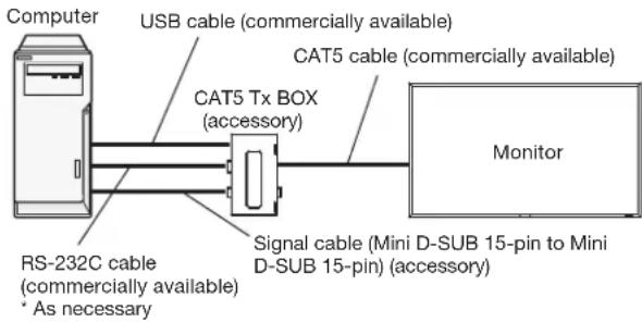
- Connect the computer and the CAT5 Tx BOX using a commercially available USB cable.
- When the USB connector isn't used for the communication control, connect with an RS-232C cable and set the input selection switch on the CAT5 Tx BOX to the RS-232C side.
NOTE:
To supply a power to the CAT5 Tx BOX, connect a USB cable also.
- Connect the RGB input connector (Mini D-SUB 15-pin) of the CAT5 Tx BOX and the D-SUB output connector of the computer using the signal cable (Mini D-SUB 15-pin to Mini D-SUB 15-pin) supplied with the monitor.
- Connect the CAT5 output connector (Modular connector 8-pin) of the CAT5 Tx BOX and the IN connector of the RGB5/CAT5 input/output connector (Modular connector 8-pin) of the monitor using a commercially available CAT5 cable.
2) Connection to multiple monitors

flowchart
graph LR
    A["Computer"] --> B["USB cable (commercially available)"]
    B --> C["CAT5 Tx BOX (accessory)"]
    C --> D["Signal cable (Mini D-SUB 15-pin to Mini D-SUB 15-pin) (accessory)"]
    D --> E["RS-232C cable (commercially available)<br>* As necessary"]
    E --> F["CAT5 cable (commercially available)"]
    F --> G["Monitor (fi rst monitor)"]
    F --> H["Monitor (second monitor)"]
- In addition to the connection described in 2-1), connect the OUT connector of the RGB5/CAT5 input/output connector (Modular connector 8-pin) of the first monitor and the IN connector of the RGB5/CAT5 input/output connector (Modular connector 8-pin) of the second monitor using a commercially available CAT5 cable.
- Connect the third and later monitors in the same way. You can connect up to 5 monitors.
NOTE:
- When different monitors need to be adjusted so that their tint can be identical, such as when using multiple screens, it is recommended to use a signal distributor (commercially available).
- To supply a power to the CAT5 Tx BOX, connect a USB cable also.
- To CAT5 output, the signal same as RGB3, RGB4, or RGB5 selected at the input switching is output.
Allowable cable length
| Connection Max | cable length/signal timing |
| One monitor 150 m | / 1920 x 1080 @60 Hz |
| Multiple monitors | 200 m / 1920 x 1080 @60 Hz(Total length of the connected cables) |
The lengths given above are based on the actual measurements using our standard signal source and the recommended cable as follows. Before installation, check the monitor operation in advance by connecting it with your computer and cables.
Recommended cable:
8-pin modular connector, straight-through, shielded, Category 5 or 5e
Commercially available cables that passed the compatibility test:
7929A of Belden, NFTP-C5e-GY of Nex1
3. Various settings involved in the CAT5 video connection
In the case of the CAT5 video connection, configure the following settings displayed on the OSD screen. (See page 47.)
1) CAT5 CABLE LENGTH
Select the cable length, and the defaults of all the adjustment values are automatically determined.
Select the length that is closest to the actual length of your cable.
2) CAT5 EQ.
Make adjustment so that blur and smear of the displayed letters and graphic objects are minimized.
3) CAT5 RED GAIN/GREEN GAIN/BLUE GAIN
When the displayed image is dark, increase each value.
When whites aren't displayed as intended, adjust the RED GAIN and BLUE GAIN values.
4) CAT5 RED SKEW/GREEN SKEW/BLUE SKEW
Adjust each value so that the color deviation in the displayed letters and graphic objects is minimized.
NOTE:
When a USB driver for the latest operation system is necessary, you can refer to the information about the USB/RS-232C conversion IC "PL-2203" at the website of Prolific Technology Inc.
The following shows the driver of which operation is checked using our computer. This information is just for reference purpose and not for guaranteeing the operation. Mitsubishi assumes no responsibilities for any losses arising out of use of this information. If you use the driver, check the operation yourself and determine the use.
- File name "PL2303_Prolifi c_DriverInstaller_v110.zip" (version V1.1.0)
Operation checked: Windows XP (32 bits), Windows Vista (32 bits), Windows 7 (32 bits)
Monitor control via RS-232C
To control this monitor from a computer via a communication, connect this monitor and the computer using an RS-232C cable (commercially available).
How to connect
- Turn off the main power switch of the computer and this monitor. If you make a connection while the power is on, it causes a failure of the devices.
- Connect the computer and this monitor using a reverse type RS-232C cable (commercially available).
- In addition, when you connect two or more monitors as shown in the illustration below, connect the RS-232C OUT connector of the first monitor and the RS-232C IN connector of the second monitor using a reverse type RS-232C cable (commercially available). By repeating the connection in the similar way, you can connect monitors in a daisy chain configuration.
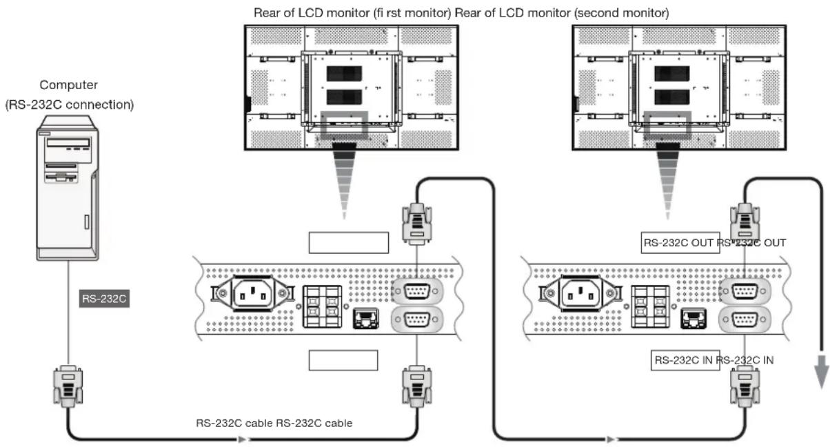
flowchart
graph TD
    A["Computer (RS-232C connection)"] --> B["RS-232C"]
    B --> C["RS-232C cable RS-232C cable"]
    C --> D["RS-232C OUT RS-232C OUT"]
    D --> E["RS-232C IN RS-232C IN"]
    E --> F["RS-232C monitor (first monitor) Rear of LCD monitor (second monitor)"]
NOTE:
When only the 25-pin serial port is equipped as the serial communication port on the computer, a conversion adapter (commercially available) is necessary for the connection.
Monitor connection using LAN
As shown in the illustration below, you can connect this monitor and a computer in network through a LAN hub. Connect the monitor and the LAN hub using a straight type LAN cable (commercially available).
How to connect
- Turn off the main power switch of the computer and this monitor. If you make a connection while the power is on, it causes a failure of the devices.
- Connect the computer and the LAN hub using a straight type LAN cable (commercially available).
- Connect this monitor and the LAN hub using a straight type LAN cable (commercially available).
- When you connect two or more monitors, you can connect the monitor and the LAN hub using a straight type LAN cable (commercially available) as described above.
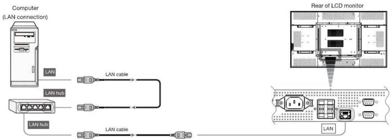
flowchart
graph TD
    A["Computer (LAN connection)"] -->|LAN| B["LAN hub"]
    A -->|LAN cable| C["Rear of LCD monitor"]
    D["LAN hub"] -->|LAN cable| C
    E["LAN"] --> C
CAUTION:
Do not connect the CAT5 IN or the CAT5 OUT connector to the LAN connector. If connected, both of the connectors may fail.
NOTE:
- When you use a cross type LAN cable (commercially available), you can connect the monitor and the computer one-to-one without using a LAN hub, however, the computer may not be supported. It is recommended to check the operation in advance.
- The image transfer function via the LAN isn't supported. This monitor isn't equipped with the host function for controlling other devices.
P-8
Connecting the power cord to the monitor
Connecting the power source
- The power outlet socket should be installed as near the equipment as possible and should be easily accessible.
- Fully insert the prongs into the power outlet socket.
Loose connection may cause noise.
NOTE:
Please refer to "Safety Precautions, Maintenance & Recommended Use" in this manual for proper selection of the AC power cord. Use the clamper to prevent accidental disconnection of the power cord.
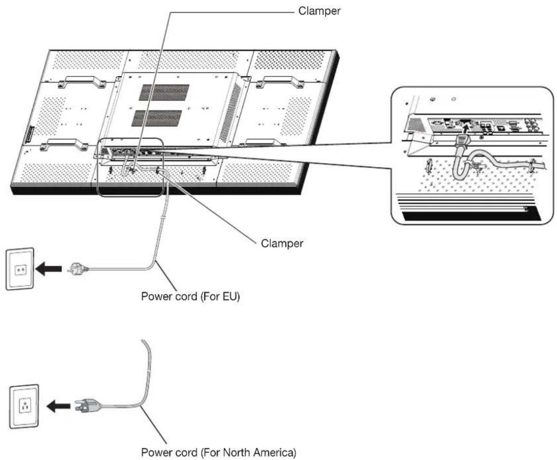
Flow of How to Using
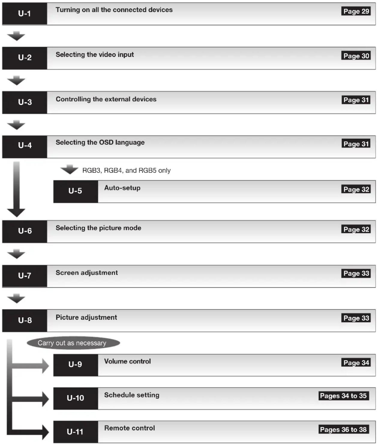
flowchart
graph TD
    A["U-1"] --> B["Turning on all the connected devices"]
    B --> C["Page 29"]
    D["U-2"] --> E["Selecting the video input"]
    E --> F["Page 30"]
    G["U-3"] --> H["Controlling the external devices"]
    H --> I["Page 31"]
    J["U-4"] --> K["Selecting the OSD language"]
    K --> L["Page 31"]
    M["U-5"] --> N["RGB3, RGB4, and RGB5 only"]
    N --> O["Page 32"]
    P["U-6"] --> Q["Selecting the picture mode"]
    Q --> R["Page 32"]
    S["U-7"] --> T["Screen adjustment"]
    T --> U["Page 33"]
    V["U-8"] --> W["Picture adjustment"]
    W --> X["Page 33"]
    Y["U-9"] --> Z["Volume control"]
    Z --> AA["Page 34"]
    AB["U-10"] --> AC["Schedule setting"]
    AC --> AD["Pages 34 to 35"]
    AE["U-11"] --> AF["Remote control"]
    AF --> AG["Pages 36 to 38"]
    AH["Carry out as necessary"] --> AI["U-9"]
    AI --> AJ["Volume control"]
    AJ --> AK["Page 34"]
    AL["U-10"] --> AM["Schedule setting"]
    AM --> AN["Pages 34 to 35"]
    AO["U-11"] --> AP["Remote control"]
    AP --> AQ["Pages 36 to 38"]
U-1 Turning on all the connected devices
Turning on external devices
1. Turn on the connected devices such as the computer and VCR.
Turning on the monitor
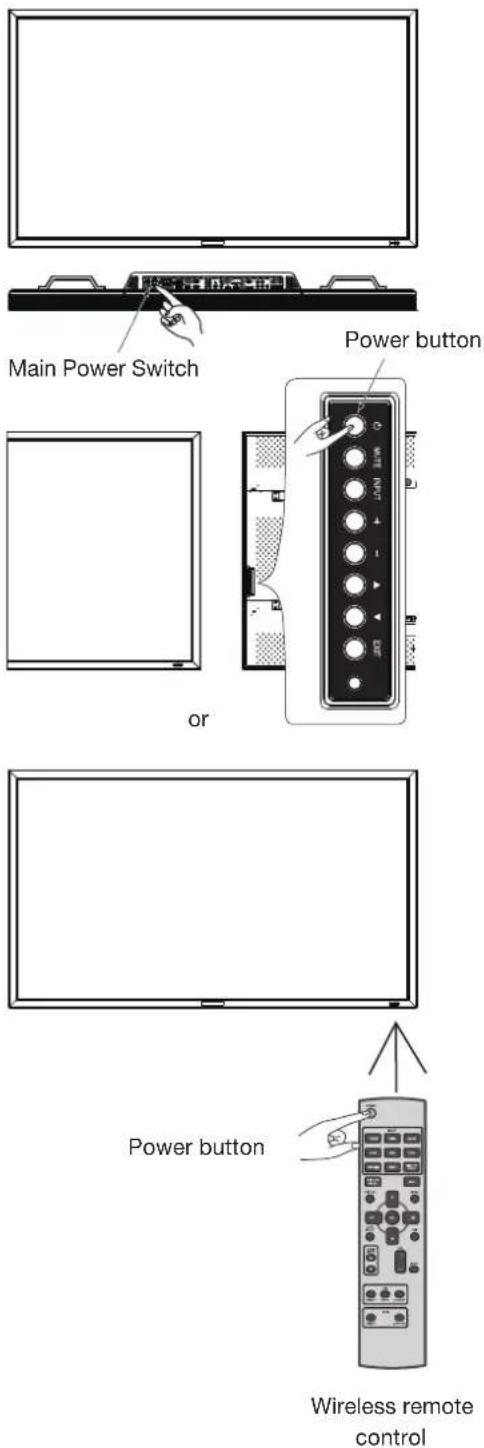
2. Turn on the Main Power Switch.
The power indicator turns on green.
The control buttons on the rear of the monitor and the wireless remote control don't work while the Main Power Switch is off (the power indicator is off).
When using them, check that the Main Power Switch is on (the power indicator is on).
3. When the power indicator glows red, press the POWER button on the monitor.
The power indicator turns green.
Power Management Function
This function reduces the power consumption of the monitor when the keyboard or the mouse is not used for a fixed period even though the power of the monitor is on.
While this function is working, the screen becomes dark and the power indicator glows green and red.
This function is available only when a computer equipped with the VESA-approved DPM Power Management function is connected to the monitor.
When the power saver in the OSD menu is turned ON, the power management function works.
RGB: When the sync signal of computer input (RGB1, 2, 3, 4, 5, or 6) is terminated, the monitor will be in the sleep mode in several seconds.
VIDEO: When the sync signal of video input (DVD/HD, VIDEO, or VIDEO) is terminated, the monitor will be in the sleep mode in approximately 10 minutes.
[Description]
DPM: Acronym for Display Power Management
NOTE:
The default power management settings (power savers) for RGB and VIDEO are ON.
Power Indicator
| Status LED | |
| Power ON Green | |
| Power OFF Red | |
| Power Standby when “SCHEDULE” is enable | Red OnGreen Blinking |
| Sleep mode Red, Green | |
| Diagnosis (Detecting failure) Red Blinking* See troubleshooting on page 55. | |
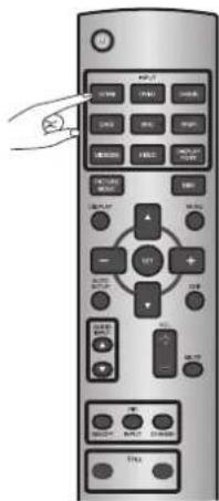
You can select the desired video input using the wireless remote control or the INPUT button on the monitor.
■ Select using the INPUT buttons on the wireless remote control.
You can select the desired video input by pressing the corresponding INPUT button on the wireless remote control.
Selectable video inputs are [RGB1] (HDMI), [RGB2] (DVI-D), [RGB3] (D-SUB), [RGB4] (BNC), [RGB5] (CAT5), [RGB6] (DISPLAY PORT), [DVD/HD] (YPbPr), [VIDEO], and [VIDEO].
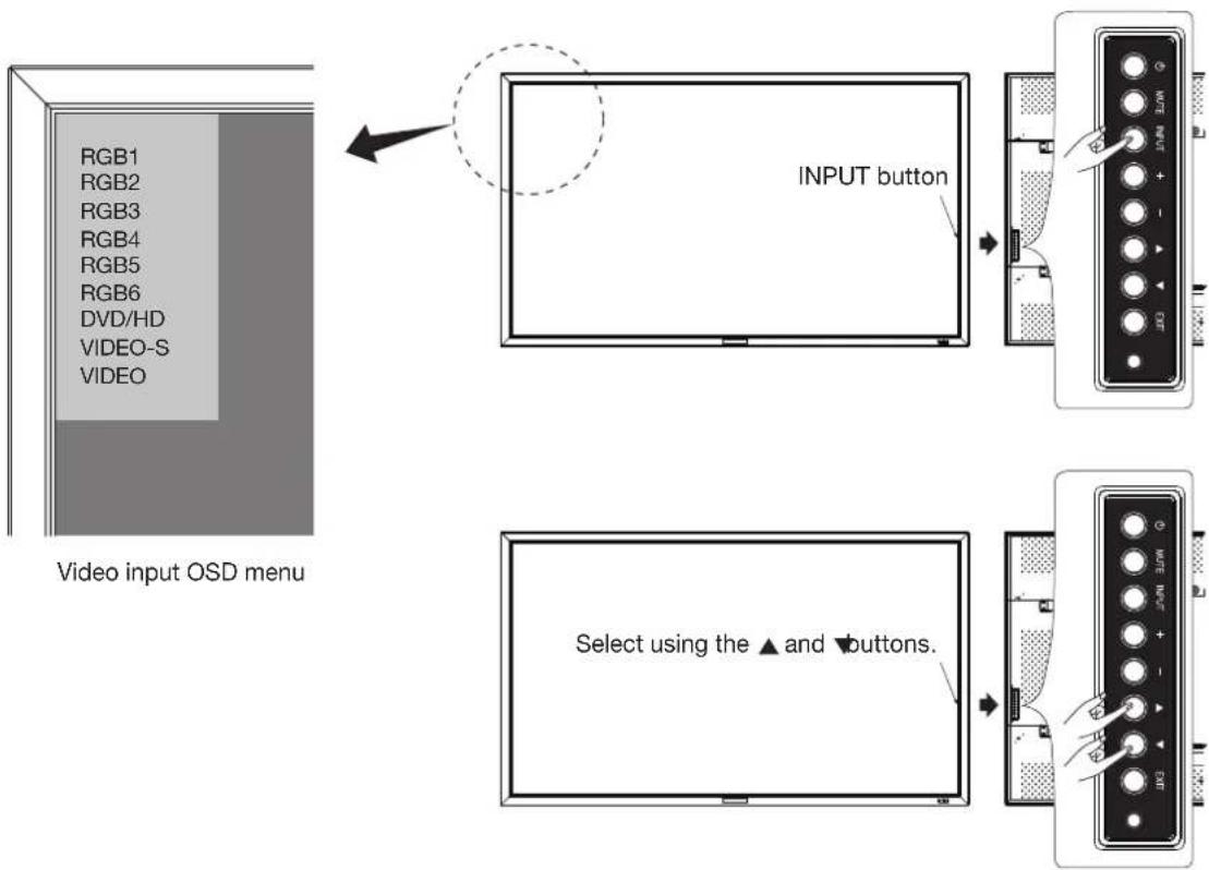
■ Select using the INPUT button on the monitor.
When you press the INPUT button on the monitor, the video input OSD menu is displayed and you can select the video input using the ▲ and ▼buttons.
Selectable video inputs are [RGB1] (HDMI), [RGB2] (DVI-D), [RGB3] (D-SUB), [RGB4] (BNC), [RGB5] (CAT5), [RGB6] (DISPLAY PORT), [DVD/HD], [VIDEO-S], and [VIDEO].
NOTE:
The selection you make doesn't complete unless you press the INPUT button while the OSD information is displayed. See page 47.
U-3
Controlling the external devices
You can control the externally connected devices to display images supplied from them.
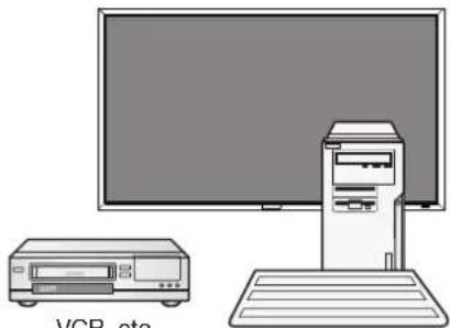
natural_image
Illustration of a desktop computer setup with monitor, tower, and CD (no text or symbols)VCR, etc.
Personal computer
U-4 Selecting the OSD language
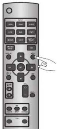
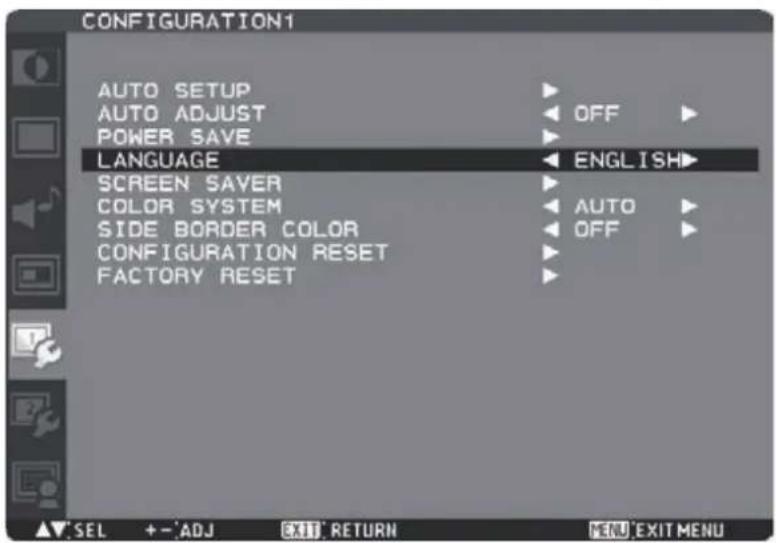
Select the OSD language using LANGUAGE in the CONFIGURATION1 menu of the OSD screen function. See page 46.
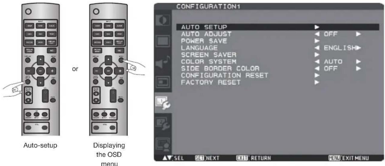
The AUTO SETUP button on the wireless remote control or AUTO SETUP in the OSD menu automatically adjusts the screen size, horizontal/vertical position, clock, clock phase, white level, and black level.
NOTE:
The auto setup works on RGB3, RGB4, and RGB5 only.
U-6
Selecting the picture mode
Using the PICTURE MODE button on the wireless remote control, you can select the picture mode suitable for images to be displayed.
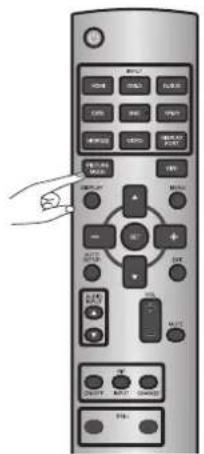
HIGHBRIGHT: The brightness is maximized.
STANDARD: Factory default setting.
sRGB: Suitable for color matching with sRGB-compliant devices.
CINEMA: Suitable for viewing movies.
U-7
Screen adjustment
When images aren't displayed properly even after the auto setup, you can alternatively adjust the screen by pressing the MENU button on the wireless remote control or the control buttons on the rear of the monitor to display the OSD menu. Using the SCREEN settings in the OSD menu, you can adjust the horizontal/vertical position, clock, clock phase, zoom mode, CUSTOM ZOOM, horizontal resolution, and vertical resolution.
NOTE:
The position adjustment works on RGB3, RGB4, RGB5, DVD/HD, VIDEO, and VIDEO only.
The clock adjustment and the resolution adjustment work on RGB3, RGB4, and RGB5 only.
The zoom adjustment works on all video inputs.
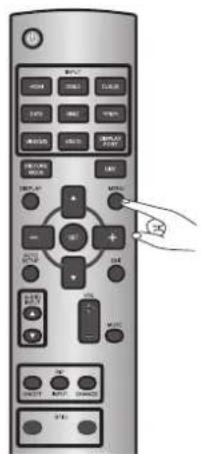
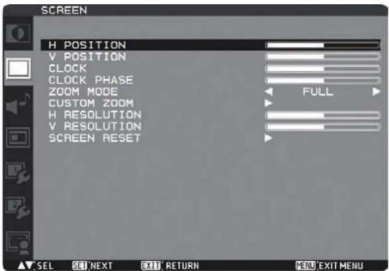
U-8
Picture adjustment
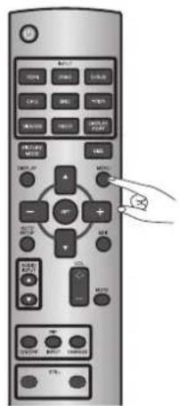
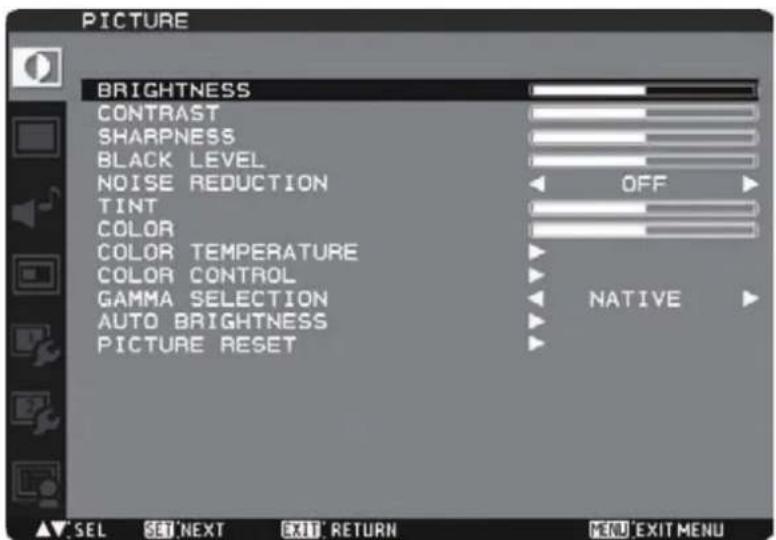
You can adjust the picture by pressing the MENU button on the wireless remote control or the control buttons on the rear of the monitor to display the OSD menu.
Using the PICTURE settings in the OSD menu, you can adjust picture settings such as the brightness, contrast, and sharpness.
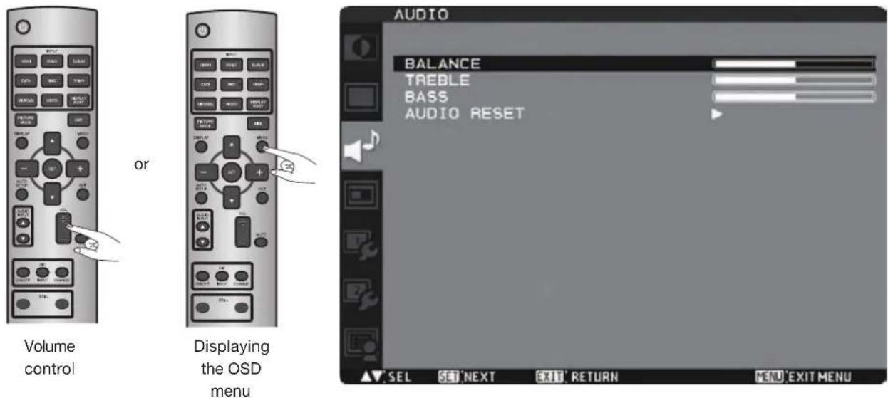
When outputting audio from the option stereo speakers, you can control the volume level using the VOL button on the wireless remote control.
In addition, you can adjust the volume by pressing the MENU button on the wireless remote control or the control buttons on the rear of the monitor to display the OSD menu. Using the AUDIO settings in the OSD menu, you can adjust the balance, treble, and bass.
U-10 Schedule setting
Carry out as necessary
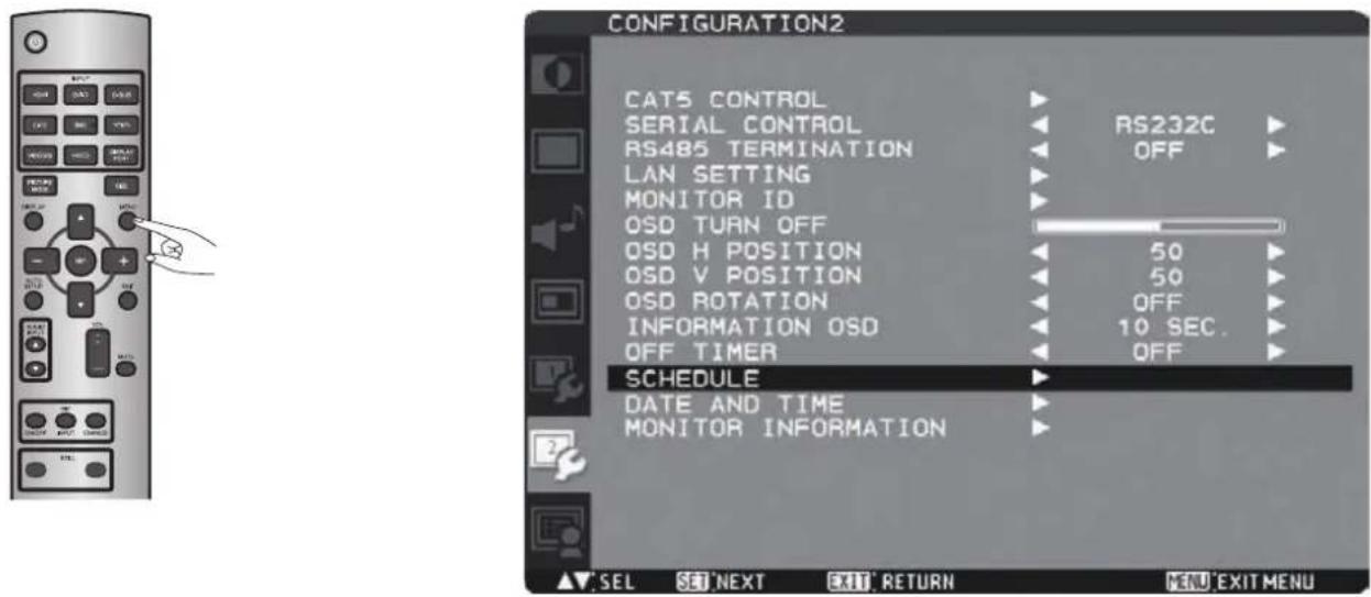
You can program the power-on/off and input selection using the SCHEDULE setting in the OSD menu that is displayed by pressing the MENU button on the wireless remote control or the control buttons on the rear of the monitor.
How to set up schedule
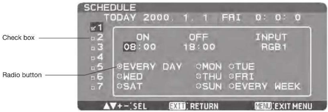
When the cursor is on any of the check boxes showing the program numbers 1 to 7 on the left side of the screen, pressing the UP (▲) or DOWN (▼) button moves the cursor vertically and pressing the PLUS (+) or MINUS (-) buttons moves it horizontally. By pressing the SET button, you can select or deselect the check boxes.
Check box: When the check box is selected, the program is enabled. When it is cleared, the program is disabled. When the SCHEDULE screen is closed, the programs you made become enabled and will be executed at the specified times.
When the cursor is on any item of the schedule settings in the white frame, pressing the PLUS (+) button moves it to the right and pressing the MINUS (-) button moves it to the left.
You can set the power-on/off time and video input by pressing the UP ( ▲) or DOWN ( ) button. You can select or deselect the radio buttons by pressing the SET button.
ON: Set the time when the power is turned on. If you don't want to set the power-on time, enter "--."
OFF: Set the time when the power is turned off. If you don't want to set to the power-off time, enter "--."
INPUT: Set the video input to be selected when the power is turned on. If you want to select the vide input that was selected before the power is turned on, enter “--.”
EVERY DAY: Select this option to execute the schedule every day. When you select EVERY DAY, you cannot select any days of the week and EVERY WEEK.
MON - SUN: Select the days of the week on which you want to execute the schedule. Unless you select EVERY WEEK, too, the selection of the days of the week is cleared after the schedule is executed one time.
EVERY WEEK: Select this option to execute the schedule on the selected days of the week, every week.
NOTE:
- Before making the schedule settings, be sure to check the current date and time using "DATE AND TIME."
- When you close the SCHEDULE screen, the settings are saved.
- When two or more schedules are enabled, they are executed in descending order of the program number, and the power is turned off upon completion of the last executed schedule.
- When there are two or more schedules having the same power-on/off time, the one having the largest program number is executed.
- You cannot set the power-on time and the power-off time to the same time.
- When OFF TIMER is ON, the schedule settings are ignored.
RS-232C/RS-485 Remote control
By connecting multiple LCD monitors and a computer using RS-232C cables (commercially available) or CAT5 cables (commercially available), you can control the monitors from the computer via the supplied CAT5 Tx BOX for the following operations:
• Power ON or OFF
- Switching between input signals
• Volume control and mute
- Auto setup
- Check of the internal temperature of the monitor, etc.
NOTE:
For connection with a 25-pin serial port connector on the computer, a conversion adapter (commercially available) is required.
1) Interface
| PROTOCOL RS-232C/RS- | 485 (CAT5) |
| BAUD RATE 9600 [bps] | |
| DATA LENGTH 8 [bit] | |
| PARITY BIT NONE | |
| STOP BIT 1 [bit] | |
| FLOW CONTROL NONE |
- For RS-232C, use RXD, TXD and GND lines (full-duplex).
- For RS-485, use RXD, TXD, RTS, DTR and GND lines in USB or RS-232C connection with the CAT5 Tx BOX (half-duplex). When you create the control program, using RTS and DTR in the transmit control of the negative logic, determine the sending of TXD and the hold time of up to 70 ms as the “sending” and then switch the control to the “receiving.”
2) Control command diagram
The command is structured by the address code, function code, data code and end code. The length of the command is different for each function.
NOTE:
- This example shows a basic command that is used when a single computer and a single monitor are connected. When you want to connect multiple monitors or perform complicated control using other commands than the basic commands, contact your dealer for advanced command specifications.
- To use terminal software, send a text file with control commands. The monitor is not compatible with the sending of commands using a keypad. (Follow the same procedure for LAN control.)
| Address code | Function code | Data code | End code | |
| HEX | 30h 30h | Function | Data | 0Dh |
| ASCII ‘0’ ‘0’ | Function | Data |
[Address code] 30h 30h (ASCII code, '0' '0'), fixed.
[Function code] Code unique to each control function.
[Data code] Data unique to each control function (Not always indicated by numerical values.)
[End code] 0Dh (In ASCII code, ‘☐’) fi xed.
3) Control sequence
(1) A command is sent from the computer to the monitor. (Commands should be sent at intervals of at least 600 ms.)
(2) The monitor sends a return command within 600 ms* after receiving and encoding the command. If the monitor fails to receive the command, it doesn't send any return command.
(3) The computer checks the return command to see that the command it sent was executed or not.
(4) The monitor sends various codes other than the return code. While RS-232C control sequence is in progress, reject other codes on the personal computer side.
*: Transmission of the return command may be delayed during signal switchover, etc.
Example: Turn the power ON (‘ ’ is for ASCII code)
| Command from computer | Command from monitor | Detail of command |
| 30 30 21 0D‘0’ ‘0’ ‘!’ | Command for POWER ON | |
| 30 30 21 0D‘0’ ‘0’ ‘!’ | Command received(Command echoed back) |
For RS-485, both of DTR and RTS lines remain Active Low while the TXD command is sent from the computer.
4) Operation commands
The operation commands configure the basic operation settings of this LCD monitor. The commands may not work during signal switchover.
The operation commands have no data codes.
| Operation ASCII HEX | ||
| POWER ON ! 21h | ||
| POWER OFF " 22h | ||
| INPUT RGB 1 _r1 5Fh 72h 31h | ||
| INPUT RGB 2 _r2 5Fh 72h 32h | ||
| INPUT RGB 3 _r3 5Fh 72h 33h | ||
| INPUT RGB 4 _r4 5Fh 72h 34h | ||
| INPUT RGB 5 _r5 5Fh 72h 35h | ||
| INPUT RGB 6 _r6 5Fh 72h 36h | ||
| INPUT VIDEO _v1 5Fh 76h 31h | ||
| INPUT DVD/HD | _v2 5Fh 76h 32h | |
| INPUT S-VIDEO | _v3 5Fh 76h 33h | |
| VOLUME UP | r06 72h 30h 36h | |
| VOLUME DOWN | r07 72h 30h 37h | |
| MUTE | ra6 72h 61h 36h | |
| AUTO SETUP r09 | 72h 30h 39h | |
- When you send the POWER ON or POWER OFF command, send the next command at intervals of at least seven seconds.
- When you send each INPUT switch command, send the next command at intervals of at least five seconds.
- In the power off mode or the sleep mode, only the POWER ON, POWER OFF, and POWER ON read command which is described on the next page can be operated.
5) Read command
The computer sends the command without datacode to the monitor.
After receiving this command, the monitor returns the command with datacode including the current status to the computer.
Example: When the computer asks the power status of the monitor, and the status of the monitor is powered-on.
| Command from computer | Command from monitor | Detail of command |
| 30 30 76 50 0D ‘0’‘0’v‘P’[enter] | Ask about the power status of the monitor. | |
| 30 30 76 50 31 0D ‘0’‘0’v‘P’‘1’[enter] | Monitor is powered-on. |
Structure of the Read-command
| ASCII | HEX | |||||
| Function | Data (Receive) | Function | Data (Receive) | |||
| POWER | ON | vP | 1 | 76 50 | 31 | |
| OFF (Sleep) | vP | 0 | 76 50 | 30 | ||
| Input | RGB-1 (HDMI) | vI | r1 | 76 49 | 72 31 | |
| RGB-2 (DVI-D) | vI | r2 | 76 49 | 72 32 | ||
| RGB-3 (D-SUB) | vI | r3 | 76 49 | 72 33 | ||
| RGB-4 (BNC) | vI | r4 | 76 49 | 72 34 | ||
| RGB-5 (CAT5) | vI | r5 | 76 49 | 72 35 | ||
| RGB-6 (DISPLAY PORT) | vI | r6 | 76 49 | 72 36 | ||
| Video | vI | v1 | 76 49 | 76 31 | ||
| DVD/HD | vI | v2 | 76 49 | 76 32 | ||
| S-VIDEO | vI | v3 | 76 49 | 76 33 | ||
| Internal temperature | Around the main board | Resolution 1°C | tc1 | (ex.) +25 74 63 31 2B 20 32 35 | ||
| Around the power supply | Resolution 1°C | tc2 | (ex.) +31 74 63 32 2B 20 33 31 | |||
LAN Remote control
By connecting the monitor and the computer using a network device such as a LAN hub as shown in Section P-7 and making the network settings using the OSD menu and RS-232C communication control, you can perform remote control using the same commands as those for RS-232C.
1. Setting procedure
(1) Set the following network parameters using the OSD menu. (See page 47.)
- DHCP client ON/OFF, IP address, subnet mask and default gateway
(2) Set the IP address described above and the port number (63007 or 3007) using the application program of your computer to perform the socket communication.
(3) Send the same control command as that for RS-232C via TCP/IP socket communication.
(4) Check the status sent from the monitor. When it is received successfully, the setting is completed.
Conf i guration and basic operation of OSD screen
Configuration of OSD screen
This monitor is equipped with the OSD (On Screen Display) function for easy screen adjustment. The OSD function allows you to control the menus displayed on the screen for brightness setting and other settings.
The OSD screen is configured as shown below.
Main Menu Screen
Main menu
Icons other than the one you selected are grayed out.

PICTURE
Page 41

CONFIGURATION1
Page 46

SCREEN
Page 43

CONFIGURATION2
Page 47

AUDIO
Page 44

ADVANCED OPTION
Page 49

PIP
Page 45
Sub menu (Adjustment items)
Adjustment items are displayed.
Adjustment status
The values adjusted by the wireless remote control and the PLUS (+) and MINUS (-) buttons on the monitor are displayed.
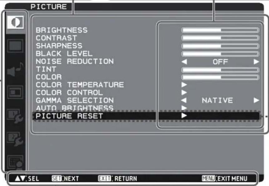
Operation buttons (Key guide)
Buttons for controlling the displayed OSD menu are displayed.
Sub menu screen
When you select a sub menu, an OSD screen is displayed.
Sub menus contain information screens, adjustment menu screens, and selection menu screens as shown below.
Sub menu screen: Picture reset (for example)
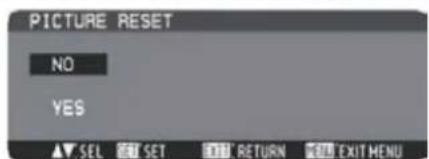
Conf i guration and basic operation of OSD screen (continued)
Basic operation of OSD
When the MENU button on the wireless remote control or the EXIT button on the monitor is pressed, the OSD screen is displayed. Select a main menu by pressing the ▲ or ▼button.
| Wireless remote control Monitor button OSD screen | ||
 Accept the selected main menu by pressing the SET button. Accept the selected main menu by pressing the SET button. | 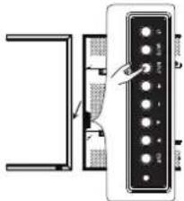 Accept the selected main menu by pressing the INPUT button. Accept the selected main menu by pressing the INPUT button. | 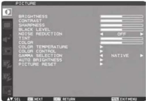 |
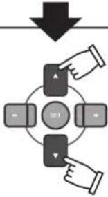 Select a sub menu by pressing the ▲ or ▼button. Select a sub menu by pressing the ▲ or ▼button. | 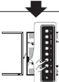 Select a sub menu by pressing the ▲ or ▼button. Select a sub menu by pressing the ▲ or ▼button. | 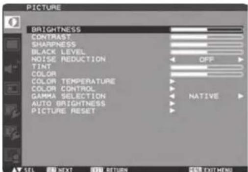 |
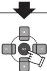 Accept the selected sub menu by pressing the SET button. Accept the selected sub menu by pressing the SET button. | 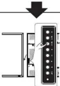 Accept the selected sub menu by pressing the INPUT button. Accept the selected sub menu by pressing the INPUT button. | 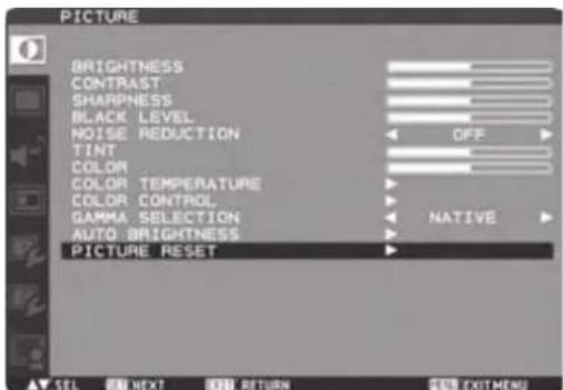 |
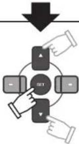 Select the setting value by pressing the ▲ or ▼button and then press the SET button to accept the setting. Select the setting value by pressing the ▲ or ▼button and then press the SET button to accept the setting. | 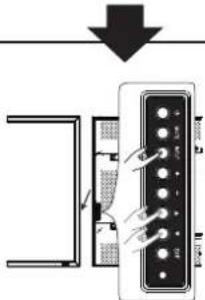 Select the setting value by pressing the ▲ or ▼button and then press the INPUT button to accept the setting. Select the setting value by pressing the ▲ or ▼button and then press the INPUT button to accept the setting. | 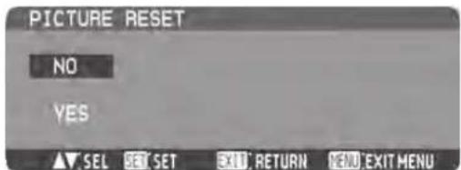 |
The OSD screen disappears when you press the MENU button on the wireless remote control once or the EXIT button on the monitor three times.
PICTURE
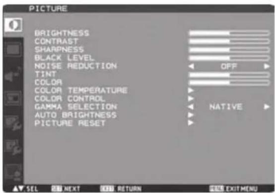
BRIGHTNESS
You can adjust the brightness.
Press the PLUS (+) button to increase the brightness. Press the MINUS (-) button to decrease the brightness.
CONTRAST
You can adjust the contrast.
Adjust the contrast using the PLUS (+) or MINUS (-) button to obtain a desired result.
NOTE: Brightness changes luminance of the backlight. Contrast changes signal levels, and therefore it is likely to lead to whiteness.
SHARPNESS
You can adjust the sharpness.
Press the PLUS (+) button to make the image look sharper.
Press the MINUS (-) button to make the image look softer.
NOTE: If you increase the sharpness setting value too much, lines may appear double. In such a case, decrease the sharpness setting value.
BLACK LEVEL
You can adjust the brightness in the dark area of the image.
Press the PLUS (+) button to brighten dark areas in the image. Press the MINUS (-) button to further darken the dark area of the image.
NOTE: This adjustment doesn't work in the sRGB picture mode.
NOISE REDUCTION
* For the VIDEO and VIDEO inputs only.
You can adjust the noise reduction level.
Press the PLUS (+) button to increase the value to lessen the noise.
TINT
* For the RGB1, DVD/HD, VIDEO, and VIDEO inputs only.
When you select TINT by pressing the SET button on the wireless remote control, the TINT screen appears and you can adjust the following.
[TINT]:
You can adjust all the colors at the same time. Press the PLUS (+) button to add a green tint. Press the MINUS (-) button to add a purple tint.
[RED], [MAGENTA], [BLUE], [CYAN], [GREEN], or [YELLOW]:
You can adjust each color individually. Press the PLUS (+) button to shift the selected color to the right around the color circle. Press the MINUS (-) button to shift the selected color to the left around the color circle.
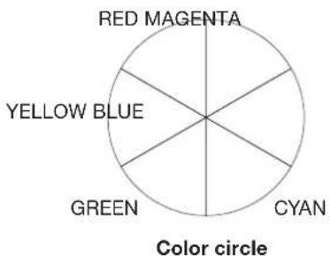
COLOR
* For the RGB1, DVD/HD, VIDEO, and VIDEO inputs only.
When you select COLOR by pressing the SET button on the wireless remote control, the COLOR screen appears and you can adjust the following.
[COLOR]:
You can adjust all the colors at the same time. Press the PLUS (+) button to deepen the colors. Press the MINUS (-) button to lighten the colors.
[RED], [MAGENTA], [BLUE], [CYAN], [GREEN], or [YELLOW]: You can adjust each color individually. Press the PLUS (+) button to deepen the selected color. Press the MINUS (-) button to lighten the selected color.
NOTE: This adjustment doesn't work in the sRGB picture mode.
COLOR TEMPERATURE
You can adjust the color temperature.
The image becomes reddish as the color temperature decreases, and it becomes bluish as the color temperature increases.
NOTE: This adjustment doesn't work in the sRGB picture mode.
COLOR CONTROL
The color levels of red, green, and blue are adjusted by the color bars.
R: Red, G: Green, B: Blue
NOTE: This adjustment doesn't work in the sRGB picture mode.
GAMMA SELECTION
You can select the gamma mode from NATIVE, S GAMMA, 2.2, 2.4 and OPTION.
NOTE: GAMMA is fixed to 2.2 in the sRGB picture mode.
AUTO BRIGHTNESS
This function controls the screen brightness depending on the ambient light for easy viewing.
In addition, it changes the screen brightness depending on the ambient light and what are displayed on the screen to reduce power consumption as low as possible.
[AUTO BRIGHTNESS]
LOCAL: The auto brightness function is enabled.
REMOTE: The auto brightness function is enabled. In addition, the monitor enters the intercommunication mode where multiple monitors are controlled collectively. (See page 52.)
OFF: This function is disabled.
[CONTROL]
PRIMARY: Select this setting to configure the monitor as Master when controlling multiple monitors collectively.
SECONDARY: Select this setting to use the monitor alone or to confi gure the monitor as Slave when controlling multiple monitors collectively.
[LIGHT FROM BACK]
YES: Select this setting when there is a light source such lighting equipment and a window behind the monitor.
NO: Select this setting when there is no light source such lighting equipment and a window behind the monitor.
[BACK WALL]
Select the following settings according to the distance between the rear of the monitor and the wall or window.
FAR: The distance is 5 meters or longer.
NEAR: The distance is 5 meters or shorter.
[FRONT SENSOR]
Select ON for normal use.
OFF: Select this setting when the sensor on the front panel is shielded.
[REAR SENSOR]
Select ON for normal use.
OFF: Select this setting when the sensor on the rear panel is shielded.
[SATURATION]
ON: The image saturation is adjusted depending on the ambient light.
OFF: Image saturation isn't adjusted.
[VIDEO DETECT]
ON: The screen brightness varies depending on what are displayed on the screen to reduce power consumption of the monitor.
OFF: The screen brightness doesn't vary and the power consumption isn't reduced.
PICTURE RESET
You can reset all the PICTURE settings to the factory defaults.
SCREEN
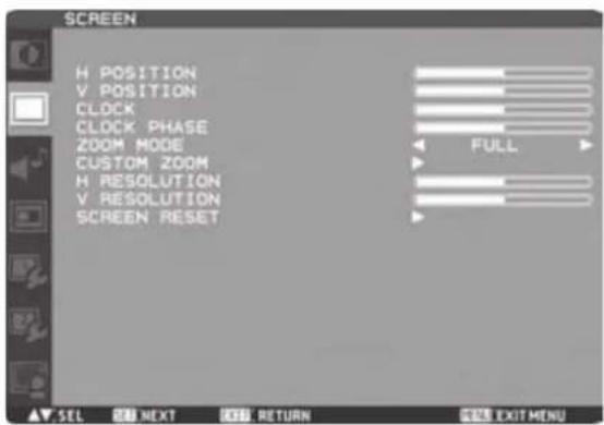
H POSITION
You can adjust the horizontal image position. Press the PLUS (+) button to move the image to the right. Press the MINUS (-) button to move the image to the left.
V POSITION
You can adjust the vertical image position. Press the PLUS (+) button to move the image up. Press the MINUS (-) button to move the image down.
CLOCK
* For the RGB3, RGB4, and RGB5 inputs only. You can adjust the image size of the computer and eliminate blurred letters. Press the PLUS (+) button to expand the width of the image on the screen to the right. Press the MINUS (-) button to narrow the width of the image on the screen to the left.
CLOCK PHASE
* For the RGB3, RGB4, and RGB5 inputs only. You can adjust the level of the periodic variation of the screen flicker.
ZOOM MODE
You can select the mode to stretch the image to fit it to the screen.
For the RGB1, RGB2, RGB3, RGB4, RGB5, and RGB6 inputs, you can select FULL, NORMAL, CUSTOM, or REAL. For DVD/HD, VIDEO, and VIDEO, you can select FULL, NORMAL, DYNAMIC, CUSTOM, or REAL.
FULL: The image is stretched to fill the screen regardless of its aspect ratio.
NORMAL: The image is stretched vertically to the full height of the screen while keeping the aspect ratio.
DYNAMIC: The image is stretched to fi ll the screen with different magnifi cations at the screen center and the screen edges.
CUSTOM: You can stretch the image horizontally and vertically as you desire using the CUSTOM ZOOM setting.
REAL: The image is displayed without being stretched or reduced.
NOTE: In the DYNAMIC mode, the top and the bottom of the image may be cropped. Full HD images are displayed as in the FULL mode.
CUSTOM ZOOM
CUSTOM ZOOM becomes selectable when you set ZOOM MODE to CUSTOM.
ZOOM: You can expand the horizontal and vertical sizes simultaneously.
H ZOOM: You can expand the horizontal size only. V ZOOM: You can expand the vertical size only.
H POSITION: Pressing the PLUS (+) button moves the image to the right. Pressing the MINUS (-) button moves the image to the left.
V POSITION: Pressing the PLUS (+) button moves the image up. Pressing the MINUS (-) button moves the image down.
H RESOLUTION
* For the RGB3, RGB4, and RGB5 inputs only. Use this setting when AUTO SETUP and AUTO ADJUST cannot obtain the horizontal resolution of the image supplied from an external device. Press the PLUS (+) button to increase the resolution. Press the MINUS (-) button to decrease the resolution.
V RESOLUTION
* For the RGB3, RGB4, and RGB5 inputs only. Use this setting when AUTO SETUP and AUTO ADJUST cannot obtain the vertical resolution of the image supplied from an external device. Press the PLUS (+) button to increase the resolution. Press the MINUS (-) button to decrease the resolution.
■ SCREEN RESET
You can reset all the SCREEN settings to the factory defaults.
AUDIO
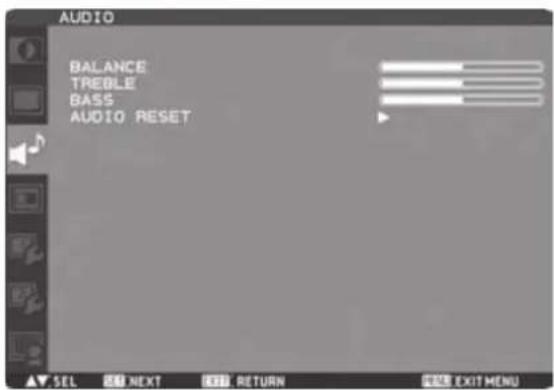
BALANCE
You can adjust the balance of the right and left volumes. Press the PLUS (+) button to decrease the left volume. Press the MINUS (-) button to decrease the right volume.
TREBLE
You can adjust the high frequency sound. Press the PLUS (+) button to increase the treble sound. Press the MINUS (-) button to decrease the treble sound.
BASS
You can adjust the low frequency sound. Press the PLUS (+) button to increase the bass sound. Press the MINUS (-) button to decrease the bass sound.
AUDIO RESET
You can reset all the AUDIO settings to the factory defaults.
PIP (PICTURE IN PICTURE)
NOTE:
The PIP and POP functions don't work in the CUSTOM and REAL picture size modes.
Refer to "PIP, POP function" for details. (See page 53.)
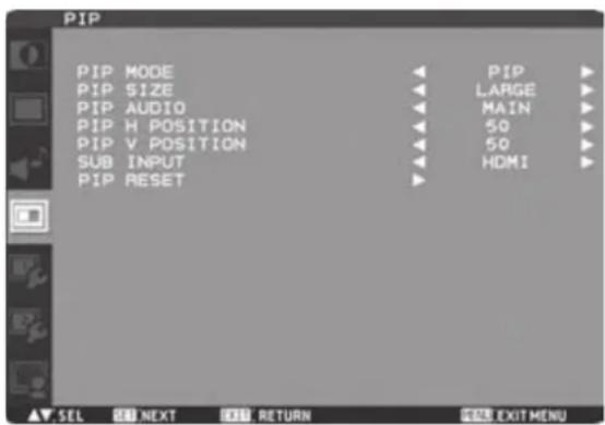
PIP MODE
You can select the PIP mode from PIP, POP, SBS ASPECT, SBS FULL, and OFF using the PLUS (+) and MINUS (-) buttons. See page 53.
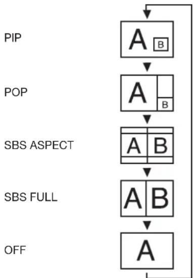
flowchart
graph TD
    A["PIP"] --> B["A"]
    B --> C["A"]
    C --> D["A"]
    D --> E["A"]
    E --> F["A"]
    F --> G["A"]
    G --> H["OFF"]
* SBS: SIDE BY SIDE
PIP SIZE
You can select the size of the sub picture displayed in the PIP mode.
You can move the sub picture by pressing the UP (▲), DOWN (▼), PLUS (+), and MINUS (-) buttons.
PIP AUDIO
You can select the audio output in the PIP mode.
When MAIN is selected, audio of the main picture is output. When SUB is selected, audio of the sub picture is output.
PIP H POSITION
You can adjust the horizontal position of the sub screen. Press the PLUS (+) button to move the sub screen to the right. Press the MINUS (-) button to move the sub screen to the left.
PIP V POSITION
You can adjust the vertical position of the sub screen. Press the PLUS (+) button to move the sub screen up. Press the MINUS (-) button to move the sub screen down.
SUB INPUT
You can select the video input for the sub screen from HDMI (RGB1), DVI-D (RGB2), D-SUB (RGB3), RGB4, DVD/HD, VIDEO, and VIDEO.
PIP RESET
You can reset all the PIP settings to the factory defaults.
CONFIGURATION1
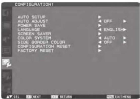
AUTO SETUP
* For the RGB3, RGB4, and RGB5 inputs only.
Press the SET button to automatically adjust the screen size, horizontal position, vertical position, clock, clock phase, white level, and black level.
AUTO ADJUST
* For the RGB3, RGB4, and RGB5 inputs only.
When AUTO ADJUST is ON, the horizontal position, vertical position, and clock phase are automatically adjusted at the time of the timing switching.
POWER SAVE
When the power saver in the OSD menu is turned ON, the power management function works.
RGB: When the sync signal of computer input (RGB1, 2, 3, 4, 5, or 6) is terminated, the monitor will be in the sleep mode in several seconds.
VIDEO: When the sync signal of video input (DVD/HD, VIDEO, or VIDEO) is terminated, the monitor will be in the sleep mode in approximately 10 minutes.
LANGUAGE
OSD control menus are available in eight languages. (English, German, Spanish, French, Italian, Swedish, Chinese, and Japanese)
SCREEN SAVER
You can set the SCREEN SAVER functions to reduce the risk of "image persistence."
GAMMA:
When you select ON, the gamma mode where image persistence is difficult to occur is used.
COOLING FAN:
When you select ON, the cooling fan always runs.
When you select AUTO, the built-in fan automatically starts running according to the operating temperature.
BRIGHTNESS:
When you select ON, the brightness decreases. MOTION:
The screen slightly moves horizontally and vertically at regular intervals to reduce the effect of the image persistence.
NOTE: When you select a time period in the MOTION setting, the monitor enlarges the image and moves it horizontally and vertically. The portions of the image out of the display area aren't visible.
To make the entire image visible all the time, arrange it to fit within 90% of the screen area at the center.
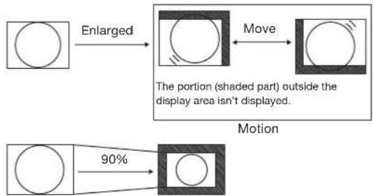
flowchart
graph TD
    A[" "] -->|Enlarged| B[" "]
    B -->|Move| C[" "]
    D[" "] -->|90%| E[" "]
    style A fill:#fff,stroke:#000
    style B fill:#fff,stroke:#000
    style C fill:#fff,stroke:#000
    style D fill:#fff,stroke:#000
    style E fill:#fff,stroke:#000
COLOR SYSTEM
* For the VIDEO and VIDEO inputs only.
You can select the color system depending on the video device you use.
AUTO: NTSC, PAL, SECAM, PAL60 or 4.43 NTSC is automatically selected.
NTSC: NTSC
PAL: PAL
SECAM: SECAM
4.43NTSC: 4.43 NTSC
PAL-60: PAL60
NOTE: When you use a video device purchased from overseas, set the COLOR SYSTEM menu.
■ SIDE BORDER COLOR
You can adjust the brightness of the black areas displayed on both sides of 4:3 images.
You can reset all the CONFIGURATION1 and CONFIGURATION2 settings to the factory defaults. Note that you cannot reset the setting of LANGUAGE, MONITOR ID, SCHEDULE, and DATE AND TIME.
FACTORY RESET
You can reset all the settings of PICTURE, SCREEN, AUDIO, CONFIGURATION1, CONFIGURATION2, and ADVANCED OPTION to the factory defaults.
Note that you cannot reset the settings of LANGUAGE and DATE AND TIME.
CONFIGURATION2
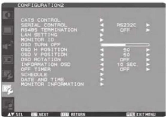
CAT5 CONTROL
[CAT5 CABLE LENGTH]
Select the cable length, and the defaults of all the adjustment values are automatically determined.
Select the length that is closest to the actual length of your cable.
[CAT5 EQ.]
Make adjustment so that blur and smear of the displayed letters and graphic objects are minimized.
[CAT5 RED GAIN, GREEN GAIN, BLUE GAIN]
When the displayed image is dark, increase each value.
When whites aren't displayed as intended, adjust the RED GAIN and BLUE GAIN values.
NOTE: Before performing the color adjustment described above, check the TINT settings on page 41.
[CAT5 RED SKEW, GREEN SKEW, BLUE SKEW]
Adjust each value so that the color deviation in the displayed letters and graphic objects is minimized.
■ SERIAL CONTROL
Select the communication interface (RS-232C, RS-485, or LAN) for the serial communication function.
For connection of the signal cable, see page 23 to 26.
RS485 TERMINATION
Turn ON or OFF the termination resistance of the RS-485 interface.
ON: Select this setting to use the monitor alone or to confi gure the monitor as the one at the end of the connection when more than one monitor is multi-connected.
OFF: Select this setting to confi gure the monitor as other than the one at the end of the connection when more than one monitor is multi-connected.
LAN SETTING
DHCP CLIENT
Select whether to use DHCP client or not.
Select OFF when not using it, and select ON when using it.
IP ADDRESS
Set the IP address of the monitor.
SUBNET MASK
Set the gateway mask.
Set it to 255.255.255.0 for normal use.
DEFAULT GATEWAY
Set the IP address of the gateway router to externally connect the local area including the monitor.
RESET
LAN settings are reset.
MONITOR ID
ID numbers for wireless remote control are assigned to MDT652S monitors that are multi-connected via RS-232C. ID numbers 1 to 26 are selectable.
OSD TURN OFF
The OSD control menu will stay on as long as it is used. The preset choices are 5 -120 seconds.
OSD H POSITION
You can adjust the horizontal position of the OSD menu.
OSD V POSITION
You can adjust the vertical position of the OSD menu.
OSD ROTATION
The OSD screen is rotated.
OFF H FLIP
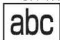
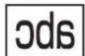
Horizontally rotated
V FLIP
Vertically rotated
INFORMATION OSD
You can enable and disable the information OSD display. The display time is selectable from 3 to 10 seconds.
NOTE: The information OSD display shows a message when the input source is switched, the input signal state is changed, or the input signal has an error.
OFF TIMER
You can select the OFF TIMER mode.
Select the time period to automatically turn off the power from 1 to 24 hours.
NOTE: When OFF TIMER is enabled, the SCHEDULE settings (see page 34) will be disabled.
SCHEDULE
You can program the LCD monitor operation schedules. (See page 35.)
Using the "SCHEDULE" function allows you to set up to seven different scheduled time intervals when the LCD Monitor will be activated.
You can select the time the monitor turns on and turns off, the day of week the monitor is activated, and which input source the monitor will use for each scheduled activation period. A check mark in the box next to the number of the schedule indicates that the selected schedule is in effect.
To select which schedule to set, use the up/down arrows to move the number (1 to 7) of the schedule.
Use the (+) and (-) buttons to move the cursor horizontally within the particular schedule. Use the ▲ and ▼buttons to increase the time and select the input port. The "SET" button is used to make a selection.
If you create a schedule but do not want to set the power on time, select “--” in the “ON” time slot.
If you do not want to use a power off time select “--” in the “OFF” time slot.
If there is no input selected (“--” showing in the input spot) the input from the previous schedule will be used.
The selection of EVERY DAY within a schedule takes priority over other schedules that are set up to operate weekly.
When schedules are overlapping, scheduled Power ON time has priority over scheduled Power OFF time.
If there are two schedules programmed for the same time, then the highest numbered schedule has priority.
When OFF TIMER is enabled, the "SCHEDULE" settings are disabled.
DATE AND TIME
You can adjust the current date and time for the internal clock.
You must set this item when using SCHEDULE.
After competing the setting, be sure to press the SET button (button 5 on page 10). When using a button of the monitor, use the INPUT button (button 5 on page 8).
■ MONITOR INFORMATION
The model name and the serial number of your monitor are displayed.
ADVANCED OPTION
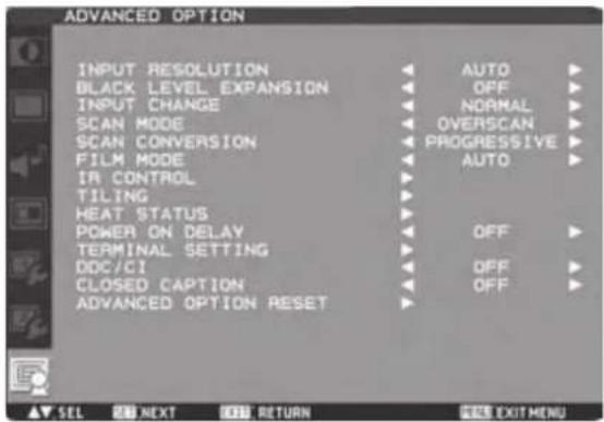
■ INPUT RESOLUTION
* For the RGB3, RGB4, and RGB5 inputs only.
You can select the following resolutions according to the input signal: AUTO, 1024x768, 1280x768, 1360x768, 1366x768, 1400x1050, 1680x1050, 1600x1200, and 1920x1200. AUTO selects the resolution automatically. The setting you select becomes effective when POWER is turned OFF and ON again.
Selects a level of black expansion from "OFF", "MIDDLE" and "HIGH." In case of go under the black cut-off level, please adjust the "Black level" in moderation on OSD menu.
■ INPUT CHANGE
You can select the time for input switching from QUICK and NORMAL. NOTE: When you select QUICK, slight noise may appear.
SCAN MODE
* For the RGB1 (HDMI), DVD/HD, VIDEO, and VIDEO inputs only.
You can select the image display area.
OVERSCAN: About 95% of the input image is displayed.
UNDERSCAN: Almost 100% of the input image is displayed.
SCAN CONVERSION
* For the RGB1 (HDMI), DVD/HD, VIDEO, and VIDEO inputs only.
You can select the IP conversion mode. PROGRESSIVE: Interlace signals are converted into progressive signals. Select this setting for normal cases. INTERLACE: Interlace signals are displayed without being converted. Though this setting is suitable for motion images, still images aren't displayed properly.
FILM MODE
You can select the film mode function.
AUTO: Images of 24 frames per second are detected, subjected to interpolation, and then displayed.
OFF: The input video signals are displayed without being subjected to any processing.
NOTE: When FILM MODE is AUTO, set SCAN CONVERSION to PROGRESSIVE. See page 49.
IR CONTROL
You can lock the wireless remote control. Select from the following two modes using the ▲ and ▼ buttons and then determine the selected mode by pressing the SET button.
NORMAL: All the remote control operations are enabled.
PRIMARY: The first MDT652S monitor of those multi-connected via RS-232C is designated as PRIMARY.
SECONDARY: MDT652S monitors other than the first one multi-connected via RS-232C are designated as SECONDARY.
LOCK: All the remote control operations are disabled.
NOTE: When you hold down the DISPLAY button on the wireless remote control for at least 5 seconds, the NORMAL mode is activated.
You can lock the wireless remote control independently from the control buttons on the rear of the monitor. See page 51.
TILING
You can enlarge an image across multiple screens. A single large screen can be configured with up to 25 monitors. You can also divide the displayed image into up to 5 pieces horizontally and vertically.
NOTE: A same video signal needs to be input to each monitor. When different monitors need to be adjusted so that their tint can be identical, it is recommended to use a signal distributor (commercially available).
When TILING is activated, PIP, POP, SBS, and STILL are disabled.
TILING doesn't work in the REAL picture size mode. H MONITORS: Select the number of images obtained by horizontal division.
V MONITORS: Select the number of images obtained by vertical division.
POSITION: Select the area you want to enlarge.
FRAME COMP.: When displaying an image across multiple monitors, you can select the mode to compensate for the bezel widths for smooth and natural display.
ENABLE: When you select ON, the image in the selected area is enlarged on the screen.
HEAT STATUS
The statuses of the cooling fan, brightness, and internal temperature are displayed.
NOTE: The cooling fan starts running according to the operating temperature or when COOLING FAN is ON in the SCREEN SAVER menu.
When the operating temperature substantially exceeds the operation guaranteed range, the message "TEMPERATURE WARNING!!" is displayed on the screen.
POWER ON DELAY
You can adjust the delayed time until the power-on mode is activated at the time of recovery from the sleep mode or power-on.
The time is selectable from OFF and 2, 4, 6, 8, 10, 20, 30, 40, and 50 seconds.
TERMINAL SETTING
You can select the mode to display the RGB1 (HDMI) or RGB2 (DVI-D) signal according to their signal format depending on their source device.
DVI-MODE:
Select this setting when displaying the RGB2 (DVI-D) signal. Select DVI-PC when the source device is a PC. Select DVI-HD when the source device is a video device.
HDMI SIGNAL:
Select this setting when displaying the RGB1 (HDMI) signal. Select LIMITED when displaying the signal that uses 16 to 235 levels of 256 levels for each of R, G, and B. This mode is used primarily when input comes from a video device. Select FULL when displaying the signal that uses all 256 levels (from level 0 to 255). This mode is used primarily when input comes from a computer.
DDC/CI
Use to turn ON or OFF the DDC/CI communication function. Select ON for normal use.
CLOSED CAPTION
You can select to display or hide captions.
OFF: Captions are hidden.
CC1: Captions are displayed in sync with the primary audio.
CC2: Information (related to the primary audio) is displayed without sync.
CC3: Captions are displayed in sync with the secondary audio.
CC4: Information (related to the secondary audio) is displayed without sync.
TT1/TT2/TT3/TT4: Four types of information not related to the displayed images are displayed. (For example, news and weather forecast.)
NOTE: Check with each supplier of your video software and external video devices in advance whether they are compliant with EIA-608-A.
If their video signals are not compliant with it, images may not be displayed correctly.
■ ADVANCED OPTION RESET
Selecting ADVANCED OPTION RESET allows you to reset all OSD settings from ADVANCED OPTION settings, except for DATE AND TIME, SCHEDULE, DVI MODE, HDMI SIGNAL, MONITOR ID, and DDC/CI.
Picture size
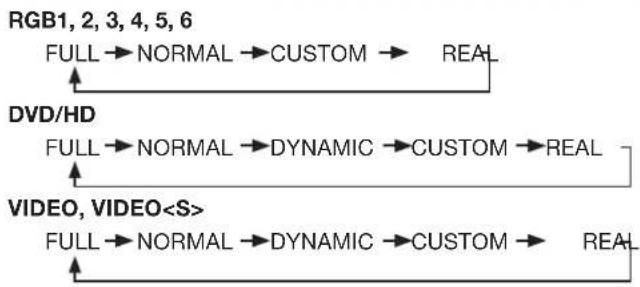
flowchart
graph TD
    A["RGB1, 2, 3, 4, 5, 6"] --> B["FULL → NORMAL → CUSTOM → REAL"]
    C["DVD/HD"] --> D["FULL → NORMAL → DYNAMIC → CUSTOM → REAL"]
    E["VIDEO, VIDEO<S>"] --> F["FULL → NORMAL → DYNAMIC → CUSTOM → REAL"]
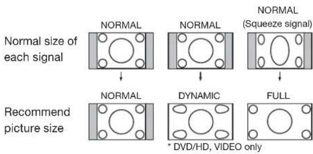
NORMAL: Images supplied from external devices such as PC and DVD fi t the screen, keeping their original aspect ratio.
FULL: Images are displayed on the entire screen.
DYNAMIC: 4:3 images are enlarged on the entire screen with non-linearity. (Round images may be cut when enlarged.)
CUSTOM (ZOOM): You can enlarge the displayed images beyond the active display area. The portions of the image out of the display area aren't visible.
REAL: Images are displayed in their original sizes.
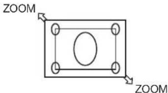
Picture mode

flowchart
graph LR
    A["RGB1, 2, 3, 4, 5, 6"] --> B["HighbRIGHT"]
    B --> C["STANDARD"]
    C --> D["sRGB"]
    E["DVD/HD, VIDEO, VIDEO<S>"] --> F["HighbRIGHT"]
    F --> G["STANDARD"]
    G --> H["CINEMA"]
Audio input change
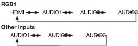
flowchart
graph LR
    A["RGB1"] --> B["HDMI"]
    B --> C["AUDIO1"]
    C --> D["AUDIO2"]
    D --> E["AUDIO3"]
    F["Other inputs"] --> G["AUDIO1"]
    G --> H["AUDIO2"]
    H --> I["AUDIO3"]
OSD information
RGB1, 2, 3, 4, 5, 6
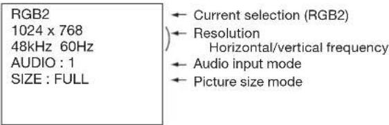
DVD/HD

VIDEO, VIDEO
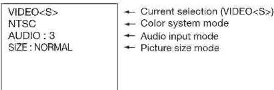
PIP, POP
Main : RGB2
Sub :VIDEO
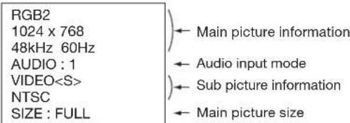
Control Lock mode
You can lock the operation buttons so that the image adjustments you made aren't changed even when the buttons are pressed.
By holding down both the ▲ and ▼ button on the monitor for 3 seconds or longer, you can lock the operation buttons. By holding down both the ▲ and ▼ button on the monitor for 3 seconds or longer again, you can unlock the operation buttons.
Supplemental information of the auto brightness function
To control multiple monitors collectively
In such a case where the tiling function is used, you can control the auto brightness function by sharing the detection result of the brightness sensor of a certain monitor among the connected monitors.
- Multi-connect the monitors using RS-232C or CAT5 cables separately sold as shown by the example below.
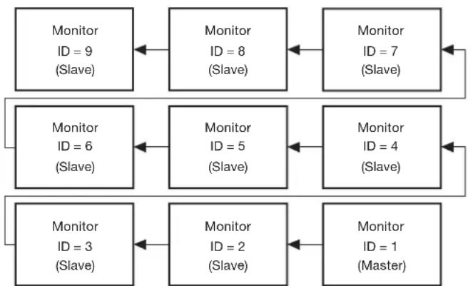
flowchart
graph TD
    A["Monitor ID = 9 (Slave)"] <--> B["Monitor ID = 8 (Slave)"]
    B <--> C["Monitor ID = 7 (Slave)"]
    D["Monitor ID = 6 (Slave)"] <--> E["Monitor ID = 5 (Slave)"]
    E <--> F["Monitor ID = 4 (Slave)"]
    G["Monitor ID = 3 (Slave)"] <--> H["Monitor ID = 2 (Slave)"]
    H <--> I["Monitor ID = 1 (Master)"]
Master: Monitor configured as Master that detects the outside light (Monitor ID is "1".)
Slave: Monitor controlled by the Master monitor (Monitor ID is other than "1".)
- Assign a monitor ID to each multi-connected MDT652S using MONITOR ID. (See page 47.)
Monitor ID is selectable from 1 to 26.
The monitor ID of the Master monitor should be "1" and those of the Slave monitors should be other than "1".
You are recommended to assign IDs to the monitors consecutively from 1, 2, 3, and on.
- Set AUTO BRIGHTNESS on the OSD screen (PICTURE) as follows.
| AUTO BRIGHTNESS CONTROL | ||
| Master monitor LOCAL PRIMARY | ||
| Slave monitors RE | MOTE SECONDARY | |
- For connection with CAT5, set [RS485 TERMINATION] of the master monitor and the slave monitor at the end to ON. Set [RS485 TERMINATION] of the other slave monitors to OFF. See page 47.
To use a computer to control the monitors
When using a computer to control the monitors, you must prepare an application software program for control by yourself.
Brightness of all the monitors can be controlled centrally using a computer, if the customer create a control application to remotely read the value from two brightness sensors of any monitor and distribute it to all monitors.
- Connect the RS-232C IN connector of the Master monitor shown above and the RS-232C connector of the computer using an RS-232C cable.
Or, using a CAT5 cable, connect the RS-232C connector of the computer to the CAT5 IN connector of the Master monitor via the CAT5 Tx BOX.
-
Assign a monitor ID to each multi-connected MDT652S using MONITOR ID. (See step 2 on page 47.)
-
Set AUTO BRIGHTNESS on the OSD screen (PICTURE) as follows.
| AUTO BRIGHTNESS CONTROL | ||
| Master monitor REMOTE SECONDARY | ||
| Slave monitors REMOTE SECONDARY | ||
-
For connection with CAT5, set [RS485 TERMINATION] of the master monitor and the slave monitors to ON. However, set [RS485 TERMINATION] of the slave monitor at the end to OFF. See page 47.
-
A control application made by the customer reads the value from two brightness sensors of any monitor and distributes it to all monitors. For the specifications of the communication commands, contact your dealer.
NOTE:
- When using CAT5 for control only, you can connect up to 26 monitors. When using the video function together, you are recommended to connect only 5 or less monitors due to the restrictions of the video function. See page 23.
- The communication control function via LAN isn't supported on the monitor alone, however, it is available when the monitor is used with the computer.
PIP, POP function
The following table shows the combinations of signal inputs with which the "PIP" and "POP" modes function. However, these modes do not function when the screen size is "CUSTOM" or "REAL".
| Sub screen | ||||||||||
| RGB1 (HDMI) | RGB2 (DVI-D) | RGB3 (D-SUB) | RGB4 (BNC) | RGB5 (CAT5) | RGB6 (DISPLAY PORT) | DVD/HD (YPbPr) | VIDEO | VIDEO | ||
| Main screen | RGB1 (HDMI) | × | × | × | × | × | × | × | ○ | ○ |
| RGB2 (DVI-D) | × | × | × | × | × | × | × | ○ | ○ | |
| RGB3 (D-SUB) | × | × | × | × | × | × | × | ○ | ○ | |
| RGB4 (BNC) | × | × | × | × | × | × | × | ○ | ○ | |
| RGB5 (CAT5) | × | × | × | × | × | × | × | ○ | ○ | |
| RGB6 (DISPLAY PORT) | × | × | × | × | × | × | × | ○ | ○ | |
| DVD/HD (YPbPr) | × | × | × | × | × | × | × | ○ | ○ | |
| VIDEO | ○ | ○ | ○ | ○ | ○ | ○ | ○ | × | × | |
| VIDEO | ○ | ○ | ○ | ○ | ○ | ○ | ○ | × | × | |
○ : Supported × : Not supported
By pressing the PIP ON/OFF button on the wireless remote control, you can change the PIP, POP, and SIDE BY SIDE modes in the order shown below.
Alternatively, you can change the modes using the PIP MODE setting of PIP in the OSD main menu. See page 45.

flowchart
graph LR
    A["A B"] --> B["A B"]
    B --> C["A B"]
    C --> D["A B"]
    D --> E["SIDE BY SIDE FULL"]
    E --> F["A"]
    style A fill:#f9f,stroke:#333
    style B fill:#ccf,stroke:#333
    style C fill:#cfc,stroke:#333
    style D fill:#fcc,stroke:#333
    style E fill:#cff,stroke:#333
    style F fill:#ffc,stroke:#333
The resolutions in the PIP, POP, and SIDE BY SIDE FULL modes are as follows:
PIP SIZE : 320 pixels X 240 pixels
< MIDDLE > : 480 pixels X 320 pixels
< LARGE > : 640 pixels X 480 pixels
POP SIZE : 450 pixels X 338 pixels
SIDE BY SIDE FULL : 960 pixels X 1080 pixels
NOTE:
When the PIP, POP, or SIDE BY SIDE FULL mode has been selected, images in the sub picture always fit the size of each mode shown above irrespective of the aspect ratio of the input image.
Remote control numbering function
By connecting multiple MDT652S monitors using RS-232C cables, you can control any one monitor or all the monitors by one remote controller.
- Assign arbitrary ID number to each of multi-connected MDT652S monitors using MONITOR ID.
ID numbers 1 to 26 are selectable.
It is recommended to assign sequential ID numbers from 1 and up.
- The remote control mode of the first MDT652S monitor is set to PRIMARY and those of the other monitors are set to SECONDARY.
- When you direct the remote controller at the remote control signal sensor of the PRIMARY monitor and press the DISPLAY button on the remote controller, the ID selection OSD appears at the upper left of the screen.
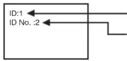
ID number of the currently viewed monitor
Select the ID number of the monitor you want to control using the +/- button on the remote controller.
The ID of the monitor you want to control is displayed at the upper left of its screen.
By selecting ALL, you can control all the multi-connected monitors.
- Direct the remote controller at the remote control signal sensor of the PRIMARY monitor.
OSD appears on the monitor having the ID number you selected.
NOTE:
When the ID selection OSD is being displayed on the PRIMARY monitor, press the DISPLAY button on the remote controller again to cancel the ID selection OSD and then control the monitor you selected.
If you set the remote control mode wrongly and remote control operation becomes unavailable, press any button on the control panel of the monitor to display the OSD screen and change the remote control mode using ADVANCED OPTION. By pressing and holding down the DISPLAY button on the remote control for 5 seconds or longer, the remote control mode is initialized to NORMAL.
No picture
- The signal cable should be securely connected to the display card/computer.
- The display card should be securely seated in its slot.
- The Main Power Switch and the computer power switch should be in the ON position.
- Make sure that the correct mode has been selected on the display card or system being used.
(Please consult the display card or system manual to change the graphics mode.) - Check the monitor and your display card with respect to the compatibility and recommended settings.
- Check the signal cable connectors for bent or pushed-in pins.
Power button does not respond
- Unplug the power cord of the monitor from the AC outlet to turn off and reset the monitor.
Image persistence
- Please be aware that LCD Technology may experience a phenomenon known as “image persistence.” Image persistence occurs when a residual or “ghost” image of a previous image remains visible on the screen. Unlike CRT monitors, LCD monitors’ image persistence is not permanent, but constant images being displayed for a long period of time should be avoided. To alleviate image persistence, turn off the monitor for as long as the previous image was displayed. For example, if an image was on the monitor for one hour and a residual image remains, the monitor should be turned off for one hour to erase the image.
NOTE:
As with all display devices, MITSUBISHI ELECTRIC recommends displaying moving images and using a moving screen saver at regular intervals whenever the screen is idle or turning off the monitor when not in use.
Image is unstable, unfocused or swimming is apparent
- Signal cable should be securely attached to the computer.
- Use the OSD Image Adjust controls to focus and adjust the display by increasing or decreasing the fine adjustment.
When the display mode is changed, the OSD Image Adjust settings may need to be re-adjusted. - Check the monitor and your display card with respect to the compatibility and recommended signal timings.
- If the displayed text is garbled, change the video mode to the non-interlace mode and use 60 Hz refresh rate.
Image of component signal is greenish
- Check to see if the DVD/HD input connector is selected.
LED on the monitor is not lit (No green or red color can be seen)
- Power Switch should be in the ON position and power cord should be connected.
- Make certain the computer is not in the power-saving mode (touch the keyboard or mouse).
RED LED on the monitor is blinking
- A certain failure may have occurred. Please contact your nearest authorized MITSUBISHI ELECTRIC service facility.
Displayed image is not sized properly
- Use the OSD Image Adjust controls to increase or decrease the coarse adjustment.
- Make sure that the correct mode has been selected on the display card or system being used.
(Please consult the display card or system manual to change the graphics mode.)
Selected resolution is not displayed properly
- Use OSD Display Mode to enter Information menu and check that the appropriate resolution has been selected. If not, select corresponding option.
No sound
- Check to see if the speaker cable is properly connected.
- Check to see if the mute is activated.
- Check to see if the volume is set to the minimum level.
Wireless remote control is not available
- Check the wireless remote control's batteries status.
- Check if the batteries are inserted correctly.
- Check if the wireless remote control is pointing at the monitor's remote sensor.
"SCHEDULE"/"OFF TIMER" function is not working properly
- The "SCHEDULE" function will be disabled when the "OFF TIMER" is set.
- If the “OFF TIMER” function is enabled and the power to the LCD monitor is turned off if the power supply is interrupted unexpectedly, then the “OFF TIMER” will be reset.
Either light vertical or horizontal stripes may appear, depending on the specific display pattern. This is no product fault or degradation.
Specifications
| Dimension (Unit: mm) | 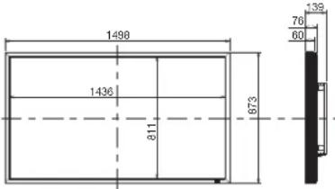 | |||
| LCD Module | Screen size (diagonal) 64.5" (1639 mm) | |||
| Panel Type VA | ||||
| Panel Pitch 0.744 mm | ||||
| Resolution 1920 x 1080 pixels (Full HD) | ||||
| Color Approximately 1.07 Billion | ||||
| Brightness (typ.) 700 cd/m | ^2 | |||
| Contrast ratio 4000 : 1 | ||||
| Viewing Angle (CR≥10) Up/Down 178°, Left/Right 178° | ||||
| Response time 8 ms (Gray to Gray) | ||||
| Viewable Size (H x V) 1428.5 mm x 803.5 mm / 56.2" x 31.6" | ||||
| Power Management VESA DPM | ||||
| Plug and Play VESA DDC2B, DDC/CI | ||||
| Auto Adjustment | Yes (Contrast / Position / Phase / Clock) | |||
| OSD user functions | Brightness, Contrast, Black level, Zoom, PIP, Screen saver, Side border color, Gamma selection, Black level expansion, Heat status, Power on delay, Schedule, Tiling, CAT5 control, Auto brightness, Closed Caption, etc. | |||
| Input / Output Signal | PC Input / Output | Input Connector | (Analog) | D-SUB 9-pin, MINI D-SUB 15-pin, BNC (R, G, B, H, V) (PC/AV Common), Modular 8-pin (CAT5) |
| (Digital) | HDMI (PC/AV Common), DVI-D (HDCP supported, PC/AV Common), DisplayPort | |||
| Output Connector | D-SUB 9-pin, MINI D-SUB 15-pin (PC/AV Common), Modular 8-pin (CAT5) | |||
| Horizontal Frequency | 15.625/15.734, 31.5 kHz - 91.1 kHz | |||
| Vertical Frequency | 50/58 Hz - 85 Hz | |||
| Video Signal | Analog: Analog RGB, Digital: TMDS (with HDCP) | |||
| Sync Signal | Analog: Separate (TTL), Sync on Green, Digital: TMDS | |||
| Supported Resolution | 640 x 480, 800 x 600, 1024 x 768, 1280 x 768, 1360 x 768, 1280 x 1024, 1600 x 1200 (Compressed/Simplified), 1920 x 1080, 1920 x 1200 (Compressed/Simplified) | |||
| AV Input / Output | Input Connector | (Analog) | Composite, Separate (Y/C), Component (Y/Pb/Pr), (PC/AV Common) | |
| (Digital) | HDMI (PC/AV Common), DVI-D (HDCP supported, PC/AV Common) | |||
| Output Connector | Analog: Composite, MINI D-SUB 15-pin (PC/AV Common) | |||
| Supported Resolution | Composite/Separate: NTSC, PAL, SECAM, 4.43 NTSC, PAL60 Component/Digital: 480i, 480p, 576i, 576p, 1080i, 720p, 1080p | |||
| Audio Input / Output | Input Connector | (Analog) | RCA pin-jack L/R x 2, Stereo mini jack | |
| (Digital) | HDMI (digital audio) | |||
| Output Connector | RCA pin-jack | |||
| Speaker Output | External Speaker Terminal (L/R), 7W + 7W (8 ohm) | |||
| Control Input / Output | Input Connector | RS-232C, CAT5 (PC/Control Common), LAN (PC/Control Common) | ||
| Output Connector | RS-232C, CAT5 (PC/Control Common) | |||
| Power Supply | Input Voltage / Current | 4.9 A - 2.0 A @AC100 - 240 V, 50/60 Hz | ||
| Power Consumption | 458 W (445 W without speaker) | |||
| Power Consumption at Power Saving | Sleep mode: Less than 2 W (less than 5 W with CAT5 input select, less than 2.6 W with LAN control select)Power switch off: Less than 1 W (less than 5 W with CAT5 input select, less than 2.6 W with LAN control select)Main power switch off: 0 W | |||
| Operation Environment | Temperature | 5 - 40°C / 41 - 104°F (Landscape Mode), 5 - 35°C / 41 - 95°F (Portrait Mode) | ||
| Humidity | 20 - 80% (without condensation) | |||
| Storage Environment | Temperature | -20 - 60°C / -4 - 140°F | ||
| Humidity | 10 - 90% (Without condensation) / 90%-3.5% x (Temp-40 °C) regarding over 40 °C | |||
| Dimension (W x H x D) | Net (without stand) | 1498 mm (W) x 873 mm (H) x 139 mm (D) / 59.0" (W) x 34.4" (H) x 5.5" (D) | ||
| Gross | 1774 mm (W) x 1200 mm (H) x 375 mm (D) / 69.8" (W) x 47.2" (H) x 14.8" (D) | |||
| Weight | Net (without stand) | Approximately 46.5 kg / 102.5 lbs | ||
| Gross | Approximately 62.4 kg / 137.6 lbs | |||
| Wall mounting interface | 8-M8 Screws holes (200 mm / 7.9" pitches) for Monitor mount | |||
| Complied regulatory and guidelines* ^1 | UL60950-1 / C-UL / EN60950-1 / CE / BSMI / GOST-R / FCC-B / DOC-B / EN55022-A / EN55024 / EN61000-3-2 / EN61000-3-3 / C-Tick / RoHS / US Mercury | |||
5) Digital RGB input (DISPLAY PORT): RGB6
| Pin No Name Pin No Name | ||
| 1 ML_Lane 3 (n) 11 GND Top | ||
| 2 GND 12 ML_Lane 0 (p) | ||
| 3 ML_Lane 3 (p) 13 CONFIG1 | ||
| 4 ML_Lane 2 (n) 14 CONFIG2 | ||
| 5 GND 15 AUX CH (p) | ||
| 6 ML_Lane 2 (p) 16 GND | ||
| 7 ML_Lane 1 (n) 17 AUX CH (n) | ||
| 8 GND 18 Hot Plug Detect | ||
| 9 ML_Lane 1 (p) 19 Return | ||
| 10 ML_Lane 0 (n) 20 DP_PWR |
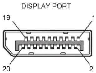
6) S-VIDEO input (MINI DIN 4-pin): VIDEO
| Pin No Name | |||
| 1 | GND | ||
| 2 | GND | ||
| 3 | Y | ( L u | |
| 4 | C | ( C h | |
m i n a n c e ) r o m a )
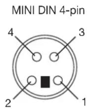
7) RS-232C input/output
(LCD monitor) (CAT5 Tx BOX)
| Pin No Name | Pin No | |||
| 1 | N | C | ||
| 2 | R | X | D | |
| 3 | T | X | D | |
| 4 | N | C | ||
| 5 | G | N | D | |
| 6 | N | C | ||
| 7 | N | C | ||
| 8 | N | C | ||
| 9 | N | C | ||
| lame | ||||
| 1 | N | C | ||
| 2 | R | X | ||
| 3 | T | X | ||
| 4 | N | C | ||
| 5 | G | N | ||
| 6 | D | S | R | |
| 7 | N | C | ||
| 8 | N | C | ||
| 9 | N | C | ||
D D D
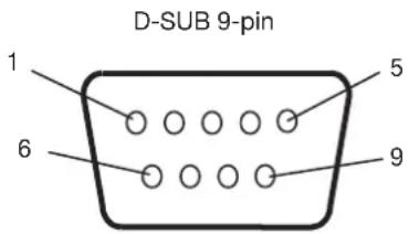
8) LAN (Modular 8-pin)
| Pin# at RJ45 | Signal | Pair |
| #1 | Orange/White stripe | |
| #2 | Orange | |
| #3 | Green/White stripe | |
| #4 | Blue | |
| #5 | Blue/White stripe | |
| #6 | Green | |
| #7 | Brown/White stripe | |
| #8 | Brown |
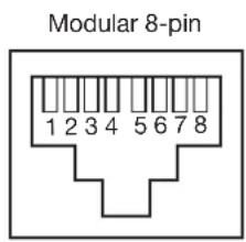

- Before use
- ご使用の前に
- Engineered Specially for Public Display Use with High Durability and High-level Specifications
- Panel Designed for Heavy Use
- High Brightness, High Contrast
- Enhanced Display Functionality for Various Commercial Use/Support for System Confi guration Suitable for Diversifi ed Applications
- 6-axis Color Adjustment Function
- Digital Zoom
- Tiling Capability with Frame compensation
- PiP, PoP and Side-by-side
- Equipped with CAT5 Analog Signal Transmission Function/Supports Max. 150-meter Cable
- CAT5 Video Connection
- Daisy-chain Connection (CAT5)
- Variable Management Functions Supporting Efficient Operation and Management
- Programmable Scheduling Function
- Screen-saver Functions
- Brightness Compensation by the Ambient Light Sensors for Enhanced Visibility and Lower Power Consumption
- Ambient Light Sensors (Brightness sensors)
- Others
- DisplayPort
- Speakers
- Remote Control
- Closed Caption
- DECLARATION OF CONFORMITY
- Canadian Department of Communications Compliance Statement
- FCC Information
- WARNING
- CAUTION
- Declaration of the Manufacturer
- Safety Precautions, Maintenance & Recommended Use
- FOR OPTIMUM PERFORMANCE, PLEASE NOTE THE FOLLOWING WHEN SETTING UP AND USING THE LCD COLOR MONITOR:
- CAUTION:
- Recommend Use
- Ergonomics
- Buttons, Switch, and Indicator
- ① Main Power Switch
- ② Remote control sensor and Power indicator
- ③ POWER button ( ⏻)
- ④ MUTE button
- ⑤ INPUT button
- ⑥ PLUS (+) button
- ⑦ MINUS (-) button
- ⑧ UP (▲ button
- ⑨ DOWN (▼ button
- ⑩ EXIT button
- ⑪ Brightness sensor (on the front and rear)
- (Reference) Control Lock mode
- NOTE:
- Connectors and Terminals
- Wireless Remote Control
- POWER button
- ② INPUT buttons
- ③ PICTURE MODE button
- ④ DISPLAY button
- ⑤ SET button
- ⑥ MINUS button (-)
- ⑦ AUTO SETUP button
- ⑧ AUDIO INPUT buttons
- ⑨ PIP (Picture-in-Picture) buttons
- [Description]
- STILL button
- SIZE button
- ⑫ MENU button
- ⑬ UP button ()
- PLUS button (+)
- EXIT button
- DOWN button (▼)
- MUTE button
- VOLUME buttons (VOL)
- How to Use the Wireless Remote Control
- Operating Range of the Wireless Remote Control
- Handling the wireless remote control
- Installing and removing the Wireless remote control batteries
- How to install the batteries
- How to remove the batteries
- CAT5 Tx BOX
- ① USB (B type)
- ② EXTERNAL CONTROL (D-SUB 9-pin)
- ③ RGB IN (MINI D-SUB 15-pin)
- ④ RGB OUT (MINI D-SUB 15-pin)
- ⑤ Composite sync signal level switch
- ⑥ CAT5 OUT (Modular connector 8-pin)
- ⑦ Input select switch (USB/RS-232C)
- ⑧ Auxiliary power supply input connector (DC IN 5 V)
- Flow of preparation
- P-1
- Preparation for installation
- P-4
- Connection procedure
- P-8
- Connecting the power cord to the monitor
- P-1 Preparation for installation
- Determine the installation location
- IMPORTANT:
- Ventilation requirements for enclosure mounting
- Using the wall mount or ceiling mount
- Lay the screen face down
- Using the monitor without the bezel
- Installing in the portrait position
- Conditions:
- How to set-up
- P-3
- Installing the optional speakers
- Before connecting the signal cable to PC and Video
- How to install the optional speakers
- Before making connections
- Prevention of disconnection of HDMI cable
- Connecting with a computer (analog connection)
- Analog connection:
- - Connection via RGB3 IN (D-SUB) connector
- - Connection via RGB4 IN (BNC: R•G•B•H•V, or R•G•B•Csync, RGB sync on green) connector
- Second monitor connection:
- Audio connection:
- Connecting with a computer (digital connection)
- Digital connection:
- - Connection via the RGB1 IN connector (HDMI)
- - Connection via the RGB2 IN connector (DVI-D)
- - Connection via the RGB6 IN connector (DisplayPort)
- - Connect an audio cable (ø3.5 mm stereo mini) (commercially available) to the AUDIO IN1 connector.
- Connecting a video device (component video/HDMI device)
- Connecting a video device (composite video/S video device)/stereo amplifi er
- CAT5 for long-distance connection or multiple-monitor connection
- Installation of the USB driver for CAT5 serial communication control
- How to install:
- 1) Installation to Windows ® XP
- 2) Installation to Windows Vista ®
- Operation check by Mitsubishi
- Connection of the CAT5 video connection function
- 1) Connection to one monitor
- 2) Connection to multiple monitors
- Various settings involved in the CAT5 video connection
- 1) CAT5 CABLE LENGTH
- 2) CAT5 EQ.
- 3) CAT5 RED GAIN/GREEN GAIN/BLUE GAIN
- 4) CAT5 RED SKEW/GREEN SKEW/BLUE SKEW
- Monitor control via RS-232C
- How to connect
- Monitor connection using LAN
- Connecting the power source
- Flow of How to Using
- U-1 Turning on all the connected devices
- Turning on external devices
- Turn on the connected devices such as the computer and VCR.
- Turning on the monitor
- Turn on the Main Power Switch.
- When the power indicator glows red, press the POWER button on the monitor.
- Power Management Function
- ■ Select using the INPUT buttons on the wireless remote control.
- ■ Select using the INPUT button on the monitor.
- U-3
- Controlling the external devices
- U-4 Selecting the OSD language
- U-6
- Selecting the picture mode
- U-7
- Screen adjustment
- U-8
- Picture adjustment
- U-10 Schedule setting
- How to set up schedule
- RS-232C/RS-485 Remote control
- 1) Interface
- 2) Control command diagram
- 3) Control sequence
- 4) Operation commands
- 5) Read command
- LAN Remote control
- Setting procedure
- Conf i guration and basic operation of OSD screen
- Configuration of OSD screen
- Main Menu Screen
- Main menu
- Sub menu (Adjustment items)
- Adjustment status
- Operation buttons (Key guide)
- Sub menu screen
- Conf i guration and basic operation of OSD screen (continued)
- Basic operation of OSD
- PICTURE
- BRIGHTNESS
- CONTRAST
- SHARPNESS
- BLACK LEVEL
- NOISE REDUCTION
- TINT
- COLOR
- COLOR TEMPERATURE
- COLOR CONTROL
- GAMMA SELECTION
- AUTO BRIGHTNESS
- [AUTO BRIGHTNESS]
- [CONTROL]
- [LIGHT FROM BACK]
- [BACK WALL]
- [FRONT SENSOR]
- [REAR SENSOR]
- [SATURATION]
- [VIDEO DETECT]
- PICTURE RESET
- SCREEN
- H POSITION
- V POSITION
- CLOCK
- CLOCK PHASE
- ZOOM MODE
- CUSTOM ZOOM
- H RESOLUTION
- V RESOLUTION
- ■ SCREEN RESET
- AUDIO
- BALANCE
- TREBLE
- BASS
- AUDIO RESET
- PIP (PICTURE IN PICTURE)
- PIP MODE
- PIP SIZE
- PIP AUDIO
- PIP H POSITION
- PIP V POSITION
- SUB INPUT
- PIP RESET
- CONFIGURATION1
- AUTO SETUP
- AUTO ADJUST
- POWER SAVE
- LANGUAGE
- SCREEN SAVER
- COLOR SYSTEM
- ■ SIDE BORDER COLOR
- FACTORY RESET
- CONFIGURATION2
- CAT5 CONTROL
- [CAT5 CABLE LENGTH]
- [CAT5 EQ.]
- [CAT5 RED GAIN, GREEN GAIN, BLUE GAIN]
- [CAT5 RED SKEW, GREEN SKEW, BLUE SKEW]
- ■ SERIAL CONTROL
- RS485 TERMINATION
- LAN SETTING
- DHCP CLIENT
- IP ADDRESS
- SUBNET MASK
- DEFAULT GATEWAY
- RESET
- MONITOR ID
- OSD TURN OFF
- OSD H POSITION
- OSD V POSITION
- OSD ROTATION
- INFORMATION OSD
- OFF TIMER
- SCHEDULE
- DATE AND TIME
- ■ MONITOR INFORMATION
- ADVANCED OPTION
- ■ INPUT RESOLUTION
- ■ INPUT CHANGE
- SCAN MODE
- SCAN CONVERSION
- FILM MODE
- IR CONTROL
- TILING
- HEAT STATUS
- POWER ON DELAY
- TERMINAL SETTING
- DDC/CI
- ■ ADVANCED OPTION RESET
- Supplemental information of the auto brightness function
- To control multiple monitors collectively
- To use a computer to control the monitors
- PIP, POP function
- Remote control numbering function
- No picture
- Power button does not respond
- Image persistence
- Image is unstable, unfocused or swimming is apparent
- Image of component signal is greenish
- LED on the monitor is not lit (No green or red color can be seen)
- RED LED on the monitor is blinking
- Displayed image is not sized properly
- Selected resolution is not displayed properly
- No sound
- Wireless remote control is not available
- "SCHEDULE"/"OFF TIMER" function is not working properly
Brand : MITSUBISHI
Model : M652-ID3450
Category : Monitor