
N.Plug - Router AIRLIVE - Free user manual and instructions
Find the device manual for free N.Plug AIRLIVE in PDF.


| Product Type | Wireless Multi-Mode Router/Repeater/Access Point |
| Brand | AirLive |
| Model | N.Plug |
| Dimensions (approx.) | 7.5 x 4.5 x 3.5 cm (plug-in design) |
| Weight (approx.) | 100 g |
| Power Supply | AC 100-240V, 50/60 Hz (direct plug-in) |
| Wireless Standards | IEEE 802.11 b/g/n, 2.4 GHz |
| Maximum Data Rate | Up to 300 Mbps (802.11n) |
| Operation Modes | Router, Access Point, Repeater, Repeating Router, Client |
| Ethernet Ports | 1x 10/100 WAN/LAN1, 1x 10/100 LAN2 |
| USB Port | USB 2.0 for 3G/3.5G dongle |
| Antenna | Detachable R-SMA antenna |
| Wireless Security | WEP, WPA, WPA2, WPA2-Mixed, WPS, MAC filter |
| Special Features | WPS push button, hardware mode switch, site survey |
| LED Indicators | Power (green), Internet (yellow), WLAN (yellow), WAN/LAN1 (green), LAN2 (green) |
| Operating Temperature | 0°C to 40°C |
| Operating Humidity | 10% to 90% non-condensing |
| Certifications | FCC, CE |
| Care Instructions | Clean with dry cloth; avoid liquids and solvents |
| Safety Precautions | Do not cover; keep away from water; ensure ventilation |
| Spare Parts | Antenna detachable; no user-serviceable internal parts |
| Repairability | Contact AirLive support for servicing |
| General Information | Compact plug-in design; multiple operation modes; supports 3G/3.5G USB and xDSL WAN |
Frequently Asked Questions - N.Plug AIRLIVE
User questions about N.Plug AIRLIVE
0 question about this device. Answer the ones you know or ask your own.
Ask a new question about this device
Download the instructions for your Router in PDF format for free! Find your manual N.Plug - AIRLIVE and take your electronic device back in hand. On this page are published all the documents necessary for the use of your device. N.Plug by AIRLIVE.
USER MANUAL N.Plug AIRLIVE
Wireless b/g/n Power Adapter Access Point
User's Manual
Air Live®
Powered by OvisLink Corp.
Copyright & Disclaimer
No part of this publication may be reproduced in any form or by any means, whether electronic, mechanical, photocopying, or recording without the written consent of OvisLink Corp.
OvisLink Corp. has made the best effort to ensure the accuracy of the information in this user's guide. However, we are not liable for the inaccuracies or errors in this guide.
Please use with caution. All information is subject to change without notice
All Trademarks are properties of their respective holders.
FCC Statement
Federal Communication Commission Interference Statement This equipment has been tested and found to comply with the limits for a Class B digital device, pursuant to Part 15 of the FCC Rules.
These limits are designed to provide reasonable protection against harmful interference in a residential installation. This equipment generates, uses and can radiate radio frequency energy and, if not installed and used in accordance with the instructions, may cause harmful interference to radio communications. However, there is no guarantee that interference will not occur in a particular installation. If this equipment does cause harmful interference to radio or television reception, which can be determined by turning the equipment off and on, the user is encouraged to try to correct the interference by one of the following measures:
● Reorient or relocate the receiving antenna.
- Increase the separation between the equipment and receiver.
- Connect the equipment into an outlet on a circuit different from that to which the receiver is connected.
- Consult the dealer or an experienced radio/TV technician for help.
FCC Caution
Any changes or modifications not expressly approved by the party responsible for compliance could void the user's authority to operate this equipment.
This device complies with Part 15 of the FCC Rules. Operation is subject to the following two conditions: (1) This device may not cause harmful interference, and (2) this device must accept any interference received, including interference that may cause undesired operation. For product available in the USA/Canada market, only channel 1\~11 can be operated. Selection of other channels is not possible.
This device and its antenna(s) must not be co-located or operation in conjunction with any other antenna or transmitter.
IMPORTANT NOTE
FCC Radiation Exposure Statement:
This equipment complies with FCC radiation exposure limits set forth for an uncontrolled environment. This equipment should be installed and operated with minimum distance 20cm between the radiator & your body.
NOTICE: the domain name of our e-mail address is being shifted from adt.com.tw to tw.bureauveritas.com. The old e-mail address is still valid till mid-2010. Please modify your address book to keep contact information correct and up-to-date.

Bluetooth
© 2009 OvisLink Corporation, All Rights Reserved
Table of Contents
1. Introduction....1
1.1 Overview....1
1.2 Firmware Upgrade and Tech Support....1
1.3 Product Features ....2
1.4 Physical Details....3
1.4.1 Status LED/WPS 3
1.4.2 Upper Switch....4
1.4.3 Bottom View 5
2. Operation Modes....7
2.1 Router Mode ....7
2.2 Access Point Mode ....8
2.3 Repeater Mode 9
2.3.1 Repeater Mode (Default Mode) 9
2.3.2 Repeating Router 9
2.3.3 Client Mode 11
3. Installation....13
3.1 Hardware Connection....13
3.1.1 AP/Router Mode....13
3.1.2 Repeater Mode....13
3.2 Login 15
3.3 Common Connection Types....18
3.3.1 Cable Modems....18
3.3.2 DSL Modems 18
3.3.3 Other Modems (e.g. Broadband Wireless) 19
4. Web Configuration....20
4.1 Setup Wizard ......21
4.1.1 Router Mode 21
4.1.2 Repeater Mode 24
4.1.3 AP Mode 26
4.2 Wireless 27
4.2.1 Basic Settings 27
4.2.1.1 AP/Router 27
4.2.1.2 Repeater....29
4.2.2 Advanced Settings 37
4.2.3 Security 39
4.2.4 Access Control....42
4.2.5 WDS Settings....43
4.2.6 Site Survey 47
4.2.7 WPS 48
4.2.8 Schedule....49
4.3 Internet Setting....50
4.3.1 WAN Interface....50
4.3.2 Port Filtering....57
4.3.3 IP Filtering ....58
4.3.4 Port Forwarding 59
4.3.5 URL Filtering 60
4.3.6 DMZ....61
4.3.7 DDNS 62
4.3.8 Router Setup....63
4.4 System....65
4.4.1 LAN Interface....65
4.4.2 Time Zone Setting....68
4.4.3 Denial-of-Service....70
4.4.4 Upgrade Firmware 71
4.4.5 Save/Reload Setting 72
4.4.6 Password....72
4.4.7 QoS....73
4.5 Ststus 75
4.5.1 Status 75
4.5.2 Statistics....76
4.5.3 Log....77
4.6 Reboot....77
5. PC Configuration ....78
5.1 Overview....78
5.2 Windows Clients....78
5.2.1 TCP/IP Settings – Overview 78
5.2.2 Checking TCP/IP Settings - Windows 2000....79
5.2.3 Checking TCP/IP Settings - Windows XP 81
5.2.4 Checking TCP/IP Settings - Windows Vista 83
5.2.5 Checking TCP/IP Settings - Windows 7 85
5.2.6 Internet Access 87
5.2.7 Macintosh Clients....89
5.2.8 Linux Clients....89
5.2.9 Other Unix Systems....90
5.2.10 Wireless Station Configuration....90
Appendix A: Troubleshooting....92
Appendix B: About Wireless LANs 95
1
Introduction
1.1 Overview
The AirLive N.Plug is a wireless B/G/N multi-mode (Repeater/AP/Router) network device with support of 3G USB dongle and xDSL WAN. The size and casing of the device are compact and well designed which is great for users want to travel light but desire for complete wireless function support as well. N.Plug in repeater mode is also great for users who are looking to extend their current wireless network but use as little configuration as possible.
If not specify, "Wireless Router" means N.Plug in the following paragraph.
1.2 Firmware Upgrade and Tech Support
If you encounter a technical issue that can not be resolved by information on this guide, we recommend that you visit our comprehensive website support at www.airlive.com. The tech support FAQ are frequently updated with latest information.
In addition, you might find new firmwares that either increase software functions or provide bug fixes for N.Plug. You can reach our on-line support center at the following link:
http://www.airlive.com/support/support_2.jsp
Since 2009, AirLive has added the “Newsletter Instant Support System” on our website. AirLive Newsletter subscribers receives instant email notifications when there are new download or tech support FAQ updates for their subscribed airlive models. To become an AirLive newsletter member, please visit: http://www.airlive.com/member/member_3.jsp
Instant Support : ☑ Subscribe Language : select...
All Products
Figure 1.1: AirLive Newsletter Support System
1.3 Product Features
■ Repeater, AP, Router all-in-one compact design!
■ Extend your coverage distance of current wireless network!
■ Configuration free with WPS
■ Easy-installation!! Plug directly onto electric socket/outlet!
■ IEEE 802.11 B/G/N standard
■ Support 3G/3.5G USB dongle and xDSL WAN
1.4 Physical Details
1.4.1 Status LED/WPS
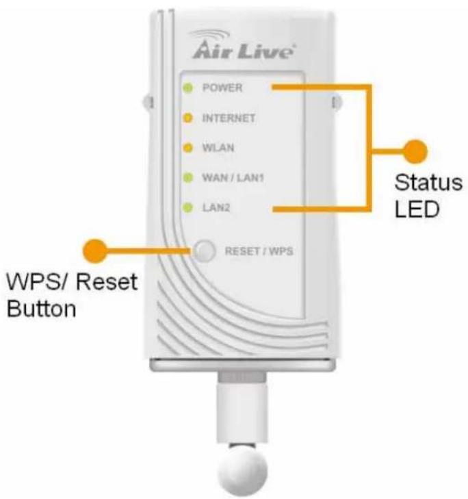
| WPS button | ||||
 | Press the physical WPS button on the Wireless Router once, or go to enable the WPS function via web configuration (Go to Wireless > WPS page), then the LED will start to flash. Please make a connection with other WPS supported device within 2 minutes. | |||
| LED Behavior | ||||
| LED | Printed | Color | Behavior | Indication |
| POWER | PWR | Green | Off | Power off |
| On | Power on | |||
| Flashing System is resetting. | ||||
| Internet | Internet | Yellow | Flashing Try to surf Internet | |
| Off Surfing Internet is successfully | ||||
| On Fail to surf Internet | ||||
| Wireless LAN | WLAN | Yellow | Off WLAN function off | |
| On WLAN link / active | ||||
| Flashing WLAN traffic transmitting | ||||
| WAN/LAN 1 port (Ethernet) | WAN/LAN1 | Green | Off No Ethernet cable connecting | |
| On Ethernet cable connected | ||||
| Flashing Receiving/ sending data | ||||
| LAN 2 Port (Ethernet) | LAN2 | Green | Off No Ethernet cable connecting | |
| On Ethernet cable connected | ||||
| Flashing Receiving/ sending data | ||||
1.4.2 Upper Switch
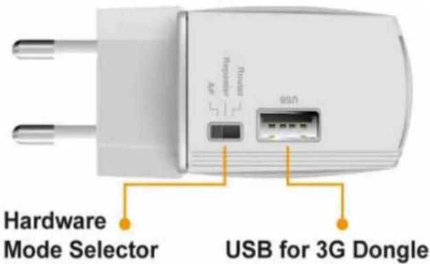
| Hardware Mode Selector and USB port | |
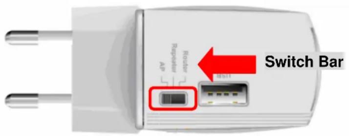
| AP In order switch to AP mode, User need to MANUALLY flick the hardware switch to the line labeled AP. The device will reboot which takes about 45 seconds. After the device has fully started, it will automatically into the selected AP mode. | |
| Repeater This is the DEFAULT mode when release from factory. In order switch to Repeater mode, User need to MANUALLY flick the hardware switch to the line labeled Repeater. The device will reboot which takes about 45 seconds. After the device has fully started, it will automatically into the selected Repeater mode. | |
| Router In order switch to Router mode, User need to MANUALLY flick the hardware switch to the line labeled Router. The device will reboot which takes about 45 seconds. After the device has fully started, it will automatically into the selected Router mode. | |
| USB Port 2.0 USB port which provide access for 3G/3.5G USB dongle. For the compatibly 3G/3.5G dongle support list, please refer to Appendix section. |
1.4.3 Bottom View
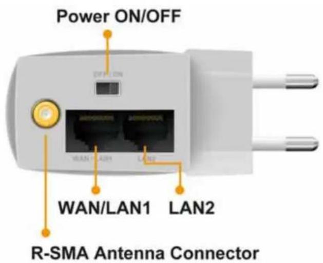
| Hardware Radio switch, WAN/LAN1 port, LAN2 port and R-SMA Antenna Connector | |
| WAN/LAN1 port (Ethernet) | When the mode sets to AP mode and user can use standard LAN cable (RJ-45 connector) to connect his/her PC with this port, it will automatically function as an "Uplink" portWhen the mode sets to Router mode, connect the ADSL or Cable Modem here with RJ45 cable. If your modem came with a cable, use the supplied cable, otherwise, use a standard LAN cable (RJ45 connectors).When the mode sets to Repeater (Repeating Router), it will serve as standard LAN port will shares the internet connection from Wireless. |
| LAN2 port (Ethernet) | When the mode sets to Router mode and user can use standard LAN cable (RJ-45 connector) to connect his/her PC with this port, it will enable the device to share the internet connection from WAN/LAN1. |
| Power ON/OFF switch | User will able to turn on and off the N.Plug with this hardware switch. |
| R-SMA Antenna Connector | User will connect the provided R-SMA antenna by screw the antenna in a clockwise direction to the bottom panel of the device. |
2
Operation Modes
This device provides operational applications with Router, AP and Repeater modes, which are mutually exclusive. This device is shipped with configuration that is functional right out of the box. If you want to change the settings in order to perform more advanced configuration or even change the mode of operation, you can manually switch to the mode you desire by the manufacturer as described in the following sections. The default setting mode is Repeater mode.
2.1 Router Mode
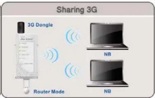
When set to Router mode, ensure you are using the wireless LAN interface, connect the Wireless Router with computer via radio frequency. In this mode, the device is supposed to connect to internet via ADSL/Cable Modem or with 3G/3.5G USB dongle. Connect the ADSL modem to the Ethernet port of the Wireless Router by Ethernet cable or Connect the 3G/3.5G USB dongle at the USB 2.0 Port. After connected successfully, user can login the web page of the Wireless Router to set up the Internet connection by using PPPoE, DHCP client, PPTP client, L2TP client or static IP.
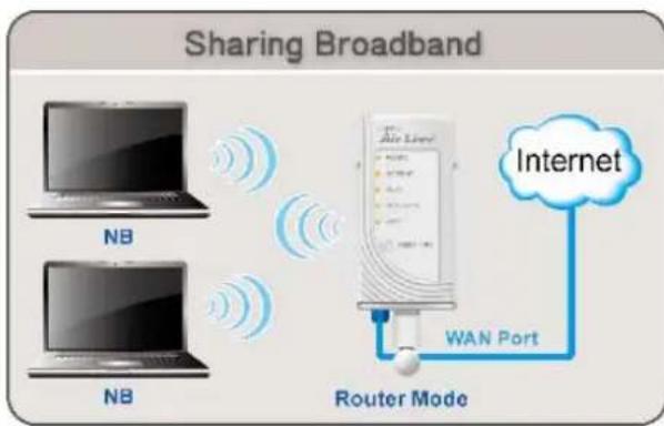
flowchart
graph TD
    A["Router Mode"] --> B["Internet"]
    C["Router Mode"] --> D["WAN Port"]
    style A fill:#f9f,stroke:#333
    style B fill:#ccf,stroke:#333
    style C fill:#cfc,stroke:#333
    style D fill:#fcc,stroke:#333
2.2 Access Point Mode
When acting as an Access Point (AP), this device connects all the stations (PC/notebook with wireless network adapter) to a wireless network.
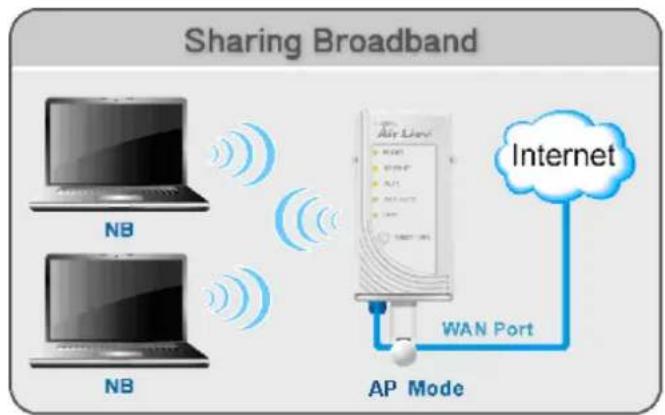
flowchart
graph TD
    A["NT"] -->|Wireless Signal| B["AP Mode"]
    C["NT"] -->|Wireless Signal| B
    B --> D["Internet"]
    B --> E["WAN Port"]
2.3 Repeater Mode
There are three selectable sub modes under Repeater.
2.3.1 Repeater Mode (Default Mode)
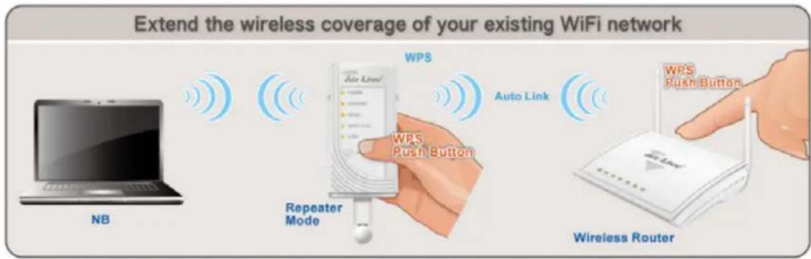
If the sub mode sets to Repeater (Universal Repeater) mode, it can also extend the wireless coverage of another wireless AP or router. But the universal repeater does not require the remote device to have WDS function. Therefore, it can work with almost any wireless device.
Note: When you are using the universal repeater mode, please make sure the remote AP/Router's WDS function is turned off.
2.3.2 Repeating Router
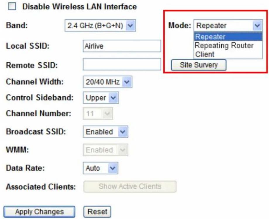
For entering Repeating Router Mode, user needs to set the hardware switch to Repeater first. Then user can access to the web user interface of N.Plug, either use the Wizard function or just go to "Wireless → Basic" for selecting the Repeating Mode via the drop down box.
Basic Settings
This page is used to configure the parameters for wireless LAN clients which may connect to your Access Point. Here you may change wireless encryption settings as well as wireless network parameters.
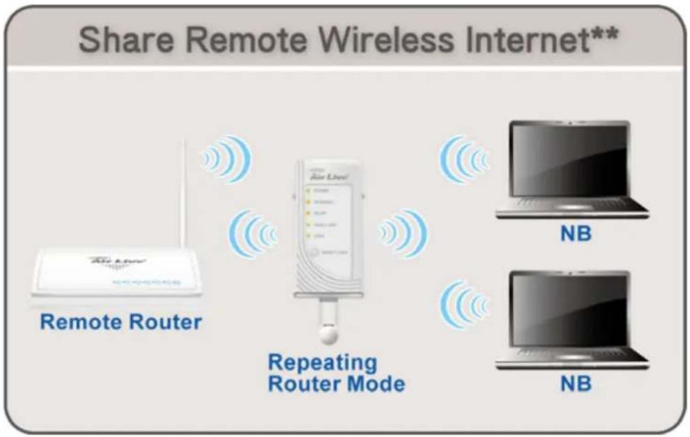
If set to Repeater (Repeating Router) mode, In Repeating Router mode, the AP will behave just the same as the Client mode for wireless function. However, Router functions are added between the wireless WAN side and the Ethernet LAN side. Therefore, the ISP Subscriber can share the Repeating Router connection without the need for extra router
flowchart
graph LR
    A["Remote Router"] --> B["Repeating Router Mode"]
    B --> C["NB"]
    B --> D["NB"]
2.3.3 Client Mode
For entering Client Mode, user needs to set the hardware switch to Repeater first. Then user can access to the web user interface of N.Plug, either use the Wizard function or just go to "Wireless → Basic" for selecting the Client Mode via the drop down box.
Basic Settings
This page is used to configure the parameters for wireless LAN clients which may connect to your Access Point. Here you may change wireless encryption settings as well as wireless network parameters.
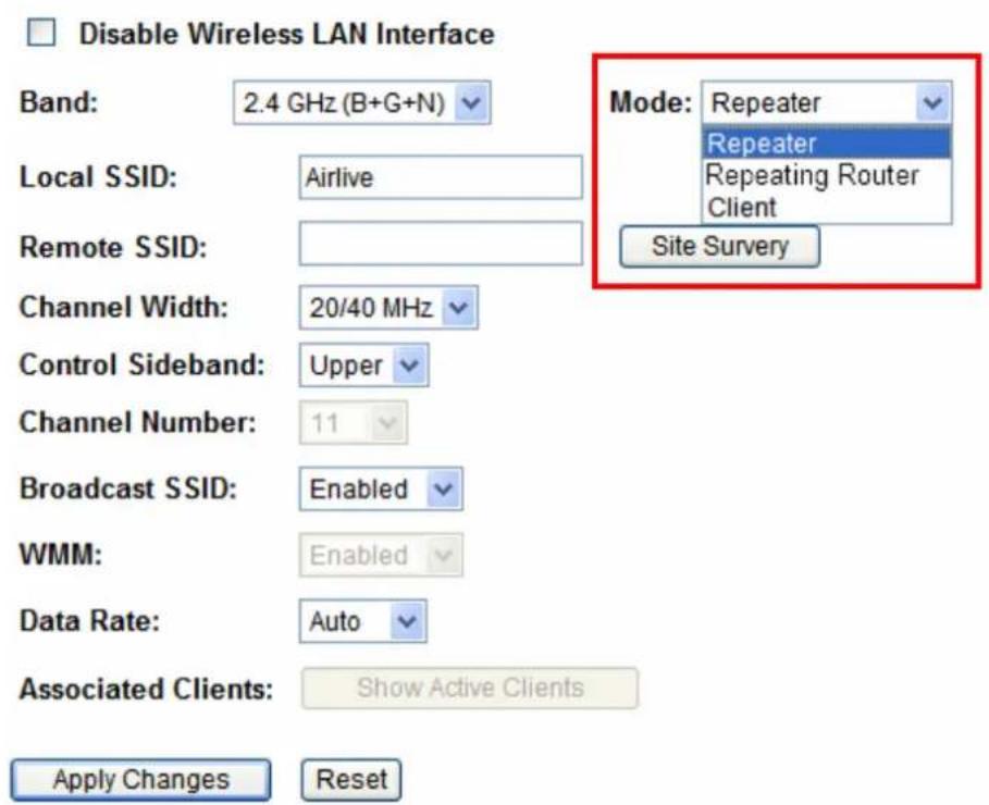
If set to Repeater (Client) mode, If set to Client mode, this device can work like a wireless station when it's connected to a computer so that the computer can send packets from wired end to wireless interface.
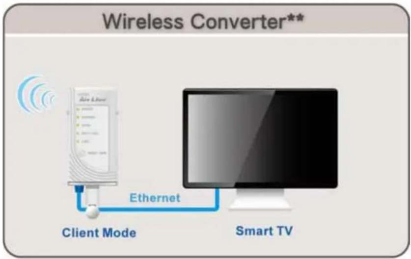
flowchart
graph LR
    A["Client Mode"] -->|Ethernet| B["Smart TV"]
3
Installation
3.1 Hardware Connection
3.1.1 AP/Router Mode
Connect via RJ-45 (Ethernet) cable
- Set N.Plug in "AP mode" or "Router" Mode by using the hardware switch at the top of N.Plug
- For Router mode, please connect Internet line to the WAN port. For 3G sharing, please connect your 3G USB dongle to the USB port.
- Connect the LAN cable to the LAN port
- If you have selected the AP mode, please make sure you have configured the PC's IP address to the same subnet as the N.Plug. (for example, 192.168.1.50)
- Open the web browser and enter N.Plug's IP address (default 192.168.1.253).
- Choose the "Wizard" to complete the setup.
3.1.2 Repeater Mode
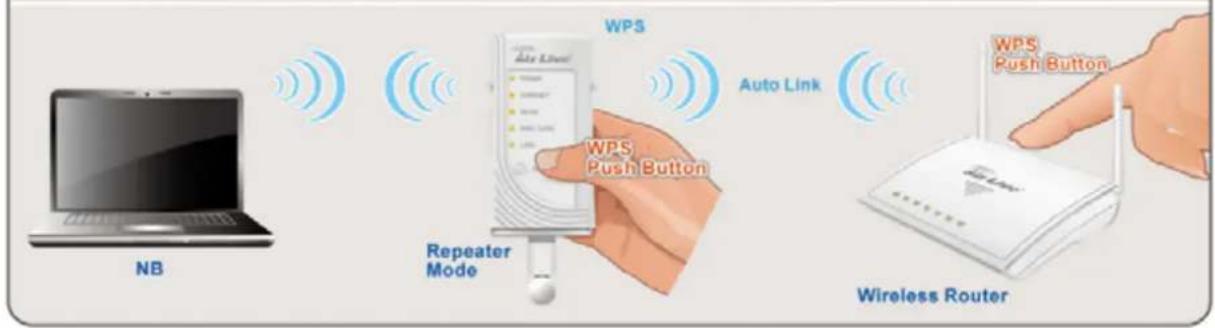
Configure one N.Plug as Repeater with WPS
- Set N.Plug in "Repeater mode" by using the hardware switch at the top of N.Plug.
- Plug-in N.Plug at the electrical outlet and wait about 2 minutes for devices to complete boot up.
- Press the WPS push button for 5 seconds on the existing AP or Router. (If your AP/Router doesn't have WPS Push Button. Please refer to its user's guide on the CD for instructions).
- Then within one minute, press the WPS push button on the N.Plug for 5 seconds until the WLAN LED is on and without flashing.
- Wait for 2 minutes for the connection to establish between N.Plug and the AP/Router.
Extend the wireless coverage of your existing WiFi network
Configure one N.Plug as Repeater without WPS
- Set N.Plug in "Repeater mode" by using the hardware switch at the top of N.Plug.
- Plug-in N.Plug at the electrical outlet and wait about 2 minutes for devices to complete boot up.
- Access WEB UI of N.Plug by enter http://192.168.1.253 in the URL box of Web Browser (IE/Firefox/Safari)
- Enter UserID/Password as admin/airlive
- After Logged in, click at Wizard at top panel of the page.
- Click at the Site survey button
- Choose the SSID of your Router/AP device, and press OK.
- Press Next Button
- Select corresponded Encryption of your Router/AP device
- Select the Pre-Shared Key format of your Router/AP device
- Enter Pre-Share Key
- Press Finish and wait for N.Plug to reboot
- Wait for 2 minutes for the connection to establish between N.Plug and the Router/AP.
3.2 Login
Step1. Make sure the connection between your computer and Wireless Router setup successfully.
Step2. Start your Web Browser.
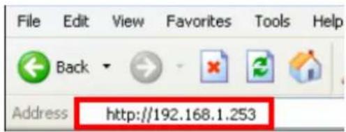
Step3. In the Address box, enter the IP address of the Wireless Router, as in this example, which uses the Wireless Router's default IP address: http://192.168.1.253.
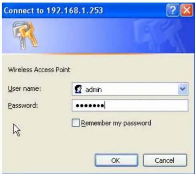
Step4. After connected successfully, the following screen will show up. Simply enter the username "admin" and password "airlive" to login (case-sensitive).
After login successfully, please click the Setup Wizard item that provides a primary configuration of this device. You may enter each screen to change the default settings step by step.

Setup Wizard
Setup Wizard
This wizard is designed to help your N.Plug up and running quickly. The wizard will ask you to enter some information in few steps. It will not change your settings until you enter all the required information and press "Finish" button on the last page.

Step 1: Wireless Settings
Please enter the network ID(SSID), you can leave it at default if you are not sure what to enter.
SSID:
Airlive
Please enter the wireless encryption key. It should be at least 8 characters. Please make sure to write it down.
Encryption Key:
We have chose the WPA2-PSK encryption type for you. if you wish to change to other encryption type, please go to "Wireless Settings -> Wireless Security" menu.
Next
If you cannot connect...
If the Wireless Router does not respond, please check following:
Step1. The Wireless Router is properly installed and connection with computer is OK, and it is already powered ON. You can test the connection by using the "Ping" command:
Step2. Please go to Start>Run...> Enter "cmd" command in the column to open the MS-DOS window.
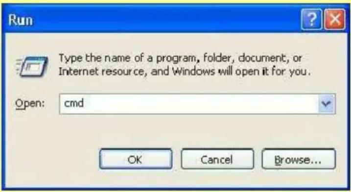
Step3. Enter the command: ping 192.168.1.253
C:>ping -t 192.168.1.253
Pinging 192.168.1.253 with 32 bytes of data:
Reply from 192.168.1.253: bytes=32 time=1ms TTL=64
Reply from 192.168.1.253: bytes=32 time<1ms TTL=64
Reply from 192.168.1.253: bytes=32 time<1ms TTL=64
Reply from 192.168.1.253: bytes=32 time<1ms TTL=64
Reply from 192.168.1.253: bytes=32 time<1ms TTL=64
Reply from 192.168.1.253 : bytes=32 time<1ms TTL=64
Reply from 192.168.1.253 : bytes=32 time<1ms TTL=64
Reply from 192.168.1.253 : bytes=32 time<1ms TTL=64
Reply from 192.168.1.253 : bytes=32 time<1ms TTL=64
Reply from 192.168.1.253 : bytes=32 time<1ms TTL=64
Ping statistics for 192.168.1.253:
Packets: Sent = 9, Received = 9, Lost = 0 (0% loss),
Approximate round trip times in milli-seconds:
Minimum = 0ms, Maximum = 1ms, Average = 0ms
Step4. If no response is received, either the connection is not working, or your PC's IP address is not compatible with the Wireless Router's IP address. (See next item.)
Step5. If your PC is using a fixed IP address, its IP address must be within the range 192.168.1.1 to 192.168.1.252 to be compatible with the Wireless Router's default IP Address of 192.168.1.253. Also, the Network Mask must be set to 255.255.255.0. See Chapter 4 - PC Configuration for details on checking your PC's TCP/IP settings.
Step6. Ensure that your PC and the Wireless Router are on the same network segment. (If you don't have a router, this must be the case.)
Step7. When set to AP/Client mode, ensure you are using the wired LAN interface, connect the computer by Ethernet cable to the Ethernet port of the Wireless Router.
Step8. When set to Router mode, ensure you are using the wireless interface, connect the Wireless Router with computer via radio frequency. The Wireless interface can only be used if its configuration matches computer's wireless settings.
3.3 Common Connection Types
3.3.1 Cable Modems
| Type Details ISP Data required | ||
| Dynamic IP Address | Your IP Address is allocated automatically, when you connect to you ISP. | Usually, none.However, some ISP's may require you to use a particular Hostname, Domain name, or MAC (physical) address. |
| Static (Fixed) IP Address | Your ISP allocates a permanent IP Address to you. | IP Address allocated to you.Some ISP's may also require you to use a particular Hostname, Domain name, or MAC (physical) address. |
3.3.2 DSL Modems
| Type Details ISP Data required | ||
| Dynamic IP Address | Your IP Address is allocated automatically, when you connect to you ISP. | None. |
| Static (Fixed) IP Address | Your ISP allocates a permanent IP Address to you. | IP Address allocated to you. |
| PPPoE You connect to the ISP only when required. The IP address is usually allocated automatically. | User name and password. | |
| PPTP Mainly used in Europe.You connect to the ISP only when required. The IP address is usually allocated automatically, but may be Static (Fixed). | 1. PPTP Server IP Address.2. User name and password.3. IP Address allocated to you, if Static (Fixed). | |
| L2TP Mainly used in Europe.You connect to the ISP only when required. The IP address is usually allocated automatically, but may be Static (Fixed). | 1. L2TP Server IP Address.2. User name and password.3. IP Address allocated to you, if Static (Fixed). | |
3.3.3 Other Modems (e.g. Broadband Wireless)
| Type Details ISP Data required | ||
| Dynamic IP Address | Your IP Address is allocated automatically, when you connect to you ISP. | None |
| Static (Fixed) IP Address | Your ISP allocates a permanent IP Address to you. | IP Address allocated to you. |
4
Web Configuration
After login successfully, please click the Setup Wizard item that provides a primary configuration of this device. You may enter each screen to change the default settings step by step.

Setup Wizard
Setup Wizard
This wizard is designed to help your NPlug up and running quickly. The wizard will ask you to enter some information in few steps. It will not change your settings until you enter all the required information and press "Finish" button on the last page.

Step 1: Wireless Settings
Please enter the network ID(SSID), you can leave it at default if you are not sure what to enter.
SSID:
Airlive
Please enter the wireless encryption key. It should be at least 8 characters. Please make sure to write it down.
Encryption Key:
We have chose the WPA2-PSK encryption type for you. if you wish to change to other encryption type, please go to "Wireless Settings -> Wireless Security" menu.
Next
4.1 Setup Wizard
The setup wizard will guide you to configure access point for first time. Please follow the setup wizard step by step.
4.1.1 Router Mode

Step 1: Wireless Settings
Please enter the network ID(SSID), you can leave it at default if you are not sure what to enter.
SSID: Airlive
Please enter the wireless encryption key. It should be at least 8 characters. Please make sure to write it down.
Encryption Key:
We have chose the WPA2-PSK encryption type for you. if you wish to change to other encryption type, please go to "Wireless Settings -> Wireless Security" menu.
Next
Step 1- Wireless Setting
User can set the SSID, wireless encryption in this page.
| SSID A SSID is referred to a network name because essentially it is a name that identifies a wireless network (case-sensitive). |
| Encryption Key We have chosen the WPS2-PSK encryption type for you. If you wish to change to other encryption type, please go to “Wireless → Basic Setting” for further configuration. |

Step 2: WAN Configuration
This page is used to configure the parameters for Internet network which connects to the WAN port of your Access Point. Here you may change the access method to static IP, DHCP, PPPoE, PPTP, USB3G or L2TP by click the item value of WAN Access type.
Attain DNS Automatically
Set DNS Manually
DNS 1:
DNS 2:
DNS 3:
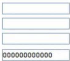
Clone MAC Address:
Enable uPNP
Enable IGMP Proxy
Enable Ping Access on WAN
□ Enable Web Server Access on WAN
√ Enable IPsec pass through on VPN connection
√ Enable PPTP pass through on VPN connection
√ Enable L2TP pass through on VPN connection
☐ Enable IPv6 pass through on VPN connection
Previous
NEXT
Step2- WAN Configuration
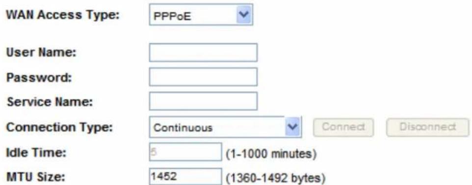
You can select the WAN connection type in this page. N.Plug supports DHCP, Static IP, L2TP, PPTP, PPPoE, BigPond, and 3G. We will take the PPPoE as an example here.
| WAN Connection Type | If the PPPoE be selected, user have to set up the user name and password according to the ISP that provided the related information. User Name: Enter the username that provide by your ISP provider. Maximum input is 32 alphanumeric characters (case sensitive).Password: Enter the password that provide by your ISP provider. Maximum input is 32 alphanumeric characters (case sensitive). |
| User Name Enter the | username that provide by your ISP provider. Maximum input is 32 alphanumeric characters (case-sensitive). |
| Password Enter the | password that provide by your ISP provider. Maximum input is 32 alphanumeric characters (case-sensitive). |
Step 3: Finish and Reboot
Now, please click on the "Finish" button if you think you have entered all the information correctly. The N.Power will reboot itself to the new settings. It will take about 2 minutes. After it finish reboot, you should be able to find your N.Power at the wireless network with the SSID you entered. Just select the SSID and connect to it. When asked for the encryption key, just enter the encryption key you have written down. Then you should be able to connect with the wireless network.
Previous
Finish
Step3- Finish and Reboot
Once the configuration is done, please click on the Finish button for applying the setting.
4.1.2 Repeater Mode

Step 1: Mode Select and Site Survey
Mode select: Please select the sub mode you want to use. You can select Repeater, Repeating Router or Client mode. For further information about those sub modes, please refer to our user's manual.
Mode: Repeater
Site Survey:
This page provides tool to scan the wireless network. If any Access Point or IBSS is found, you could choose to connect it manually when client mode is enabled.
Site Survey
Step 1- Mode Selection and Site Survey
User can further select one of the three sub mode in this page. There are three sub modes supported by N.Plug. We will take Repeater mode as an example here.
| Mode Selection Repeater:Using repeater mode, N.Plug can also extend the wireless coverage of another wireless AP or router.Repeating Router:In Repeating Router mode, the AP will behave just the same as the Client mode for wireless function. However, router functions are added between the wireless WAN side and the Ethernet LAN side. Therefore, the WISP subscriber can share the WISP connection without the need for extra router.Client:If set to Client (Infrastructure) mode, N.Plug can work like a wireless station when it's connected to a computer so that the computer can send packets from wired end to wireless interface. |
Site Survey
| SSID | BSSID | Channel | Type | Encrypt | Signal | Select |
| Costa | 06:4f:68:50:18:cf | 1 (B+G) | AP | WPA-PSK/WPA2-PSK | 66 | |
| Relax | 00:1f:1ff3:cf:0e | 9 (B+G+N) | AP | WPA2-PSK | 48 |
Next
| Site Survey | You can use this page to search the remote AP you wanted. After clicking on the Site Survey button, N.Plug will list all availability AP's or Routers in range. Please select your desired AP and click. |

Step 2: SSID and Encryption Setting
SSID:
Below is the SSID you picked out from previous step. if it is not the one you desired, please press "Previous" button for going back to the previous step.
By default, the SSID will be also applied to local SSID, and if you need to further configure your local SSID, please go to "Wireless -> Basic" for manually setting.
SSID: airlive
Encryption:
Please choose the encryption method and key used by the remote AP. By default, the encryption method will be also applied to local SSID, and if you need to further configure your local encryption, please go to "Wireless -> Security" for manually setting.
Encryption: WPA2
Authentication Mode:
WPA2 Cipher Suite:
Pre-Shared Key Format:
Pre-Shared Key:
Personal (Pre-Shared Key)
TKIP AES
Passphrase
Previous
Finish
Step 2- Set Encryption
User can set the SSID manually and configure the encryption of the wireless connection here.
Once the configuration is done, please click on the Finish button for applying the setting.
4.1.3 AP Mode

Step 1: Wireless Settings
Please enter the network ID(SSID), you can leave it at default if you are not sure what to enter.
SSID: Airlive
Please enter the wireless encryption key. It should be at least 8 characters. Please make sure to write it down.
Encryption Key:
We have chose the WPA2-PSK encryption type for you. if you wish to change to other encryption type, please go to "Wireless Settings -> Wireless Security" menu.
Next
Step 1- Wireless Setting
User can select the set the SSID, wireless encryption in this page.
| SSID A SSID is referred to a network name because essentially it is a name that identifies a wireless network (case-sensitive). |
| Encryption Key We have chose the WPS2-PSK encryption type for you. If you wish to change to other encryption type, please go to “Wireless → Basic Setting” for further configuration. |
Step 2: Finish and Reboot
Now, please click on the "Finish" button if you think you have entered all the information correctly. The N.Power will reboot itself to the new settings. It will take about 2 minutes. After it finish reboot, you should be able to find your N.Power at the wireless network with the SSID you entered. Just select the SSID and connect to it. When asked for the encryption key, just enter the encryption key you have written down. Then you should be able to connect with the wireless network.
Previous
Finish
Step 2- Finish and Reboot
Once the configuration is done, please click on the Finish button for applying the setting.
4.2 Wireless
4.2.1 Basic Settings
4.2.1.1 AP/Router
Basic Settings
This page is used to configure the parameters for wireless LAN clients which may connect to your Access Point. Here you may change wireless encryption settings as well as wireless network parameters.
□ Disable Wireless LAN Interface
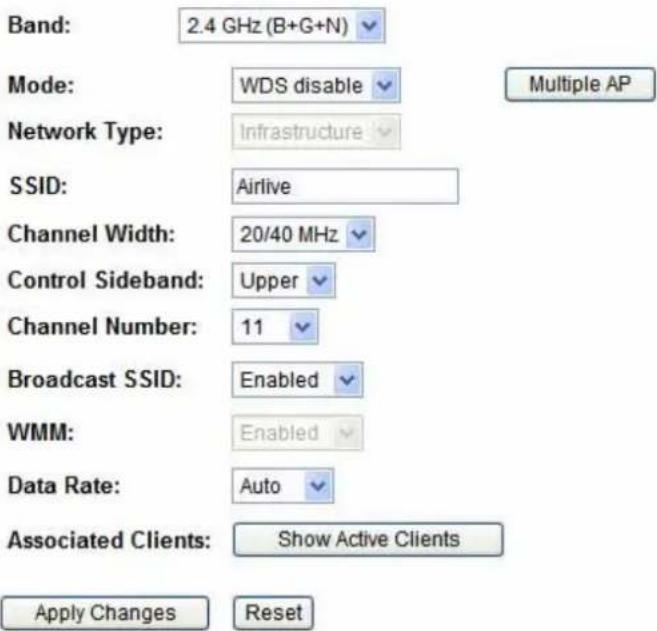
| Disable Wireless LAN Interface | Check to disable the wireless function. If the wireless LAN interface be disabled, the WLAN LED on the top will be off. |
| Band You can choose | one mode of the following you need. The default is2.4GHz (B+G+N) mode.2.4GHz (B): 802.11b supported rate only.2.4GHz (G): 802.11g supported rate only.2.4GHz (N): 802.11n supported rate only.2.4GHz (B+G): 802.11b supported rate and 802.11gsupported rate.2.4GHz (G+N): 802.11g supported rate and 802.11n supported rate.2.4GHz (B+G+N): 802.11b, 802.11g and 802.11n supported rate. |
| WDS | User can select WDS disable/ WDS enable/ WDS only from the pull-down list. |
| Network Name (SSID) | A SSID is referred to a network name because essentially it is a name that identifies a wireless network(case-sensitive).Multiple APsThis page shows and updates the wireless setting for multiple APsMultiple APsThis page shows and updates the wireless setting for multiple APs.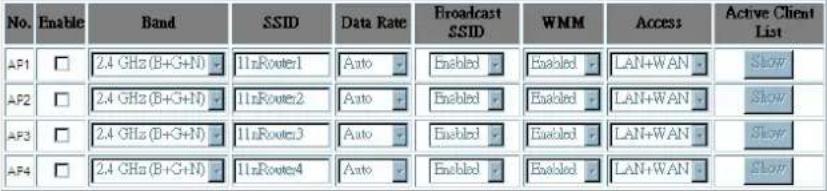 Apply Changes ResetUser can set up the multiple AP here. To enable one of the APs from 1~4, then setup the wireless settings from the pull-down list. Apply Changes ResetUser can set up the multiple AP here. To enable one of the APs from 1~4, then setup the wireless settings from the pull-down list. |
| Channel Width | This function will be available under 2.4GHz (N), 2.4GHz (G+N), 2.4GHz (B+G+N) mode. Select 20MHz the channel number will be form 5~11 and auto; Select 20/40MHz channel width the channel number will be form 1~11 and auto. Default is 20/40MHz. |
| Control Sideband | This function will be available under 2.4GHz (N), 2.4GHz (G+N), 2.4GHz (B+G+N) mode. Select upper or lower form the pull-down list, default is upper. |
| Channel Number The | channel number base on the channel width you select. |
| Broadcast SSID Enabled | This Wireless Router will show its network name(SSID)to stations. Disabled: This Wireless Router will hide the network name to stations. If stations want to connect to this Wireless Router, this Router's network name(SSID) should be known in advance to make a connection. |
| WMM The Wi-Fi Multiple Media function is available under 2.4GHz (B), 2.4GHz (G) and 2.4GHz (B+G) band, and it is disabled under 2.4GHz (N), 2.4GHz (G+N) and 2.4GHz (B+G+N) band. | |
| Data Rate | There are several data rate that you can select from the pull-down menu. |
| Associated Clients | ClickShow Active Clientsbutton to show all connected clients.Active Wireless Client TableThis table shows the MAC address, transmission, reception packet counters and encrypted status for each associated wireless client. |
4.2.1.2 Repeater
□ Disable Wireless LAN Interface
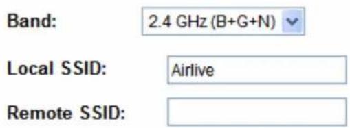
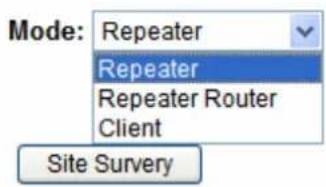
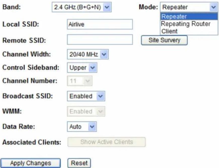
In Repeater Mode, there are three sub modes, Repeater, Repeating Router and Client mode. According to different sub mode selected, the web will be slightly different for user to do the proper setting. Because in the repeater mode, the wireless setting will be mostly the same the upstream Router or AP, if not necessary, we recommend you to use the site survey or WPS function for getting these values automatically.
Repeater
Basic Settings
This page is used to configure the parameters for wireless LAN clients which may connect to your Access Point. Here you may change wireless encryption settings as well as wireless network parameters.
□ Disable Wireless LAN Interface
| Disable Wireless LAN Interface | Check to disable the wireless function. If the wireless LAN interface be disabled, the WLAN LED on the top will be off. |
| Band You can choose | one mode of the following you need. The default is2.4GHz (B+G+N) mode.2.4GHz (B): 802.11b supported rate only.2.4GHz (G): 802.11g supported rate only.2.4GHz (N): 802.11n supported rate only.2.4GHz (B+G): 802.11b supported rate and 802.11g supported rate.2.4GHz (G+N): 802.11g supported rate and 802.11n supported rate.2.4GHz (B+G+N): 802.11b, 802.11g and 802.11n supported rate. |
| Local SSID A SSID is | referred to a network name because essentially it is a name that identifies a wireless network(case-sensitive). |
| Remote SSID In Repeater Mode, the remote SSID should be the same with the repeated Router or AP. | |
| Channel Width | This function will be available under 2.4GHz (N), 2.4GHz (G+N), 2.4GHz (B+G+N) mode. Select 20MHz the channel number will be form 1~11 and auto; Select 20/40MHz channel width the channel number will be form 5~11 and auto. Default is 20/40MHz. |
| Control Sideband | This function will be available under 2.4GHz (N), 2.4GHz (G+N), 2.4GHz (B+G+N) mode. Select upper or lower form the pull-down list, default is upper. |
| Channel Number The channel number will be set the same as remote Ap automatically. | |
| Broadcast SSID | Enabled: This Wireless Router will show its network name(SSID) to stations.Disabled: This Wireless Router will hide the network name to stations. If stations want to connect to this Wireless Router, this Router's network name(SSID) should be known in advance to make a connection. |
| WMM The Wi-Fi Multiple Media function is available under 2.4GHz (B), 2.4GHz (G) and 2.4GHz (B+G) band, and it is disabled under 2.4GHz (N), 2.4GHz (G+N) and 2.4GHz (B+G+N) band. | |
| Data Rate | There are several data rate that you can select from the pull-down menu. |
| Associated Clients | Click Show Active Clients button to show all connected clients. |
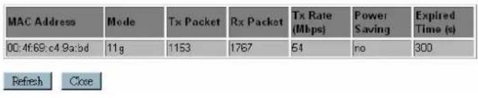
Active Wireless Client Table
This table shows the MAC address, transmission, reception packet counters and encrypted status for each associated wireless client.
Repeating Router
Basic Settings
This page is used to configure the parameters for wireless LAN clients which may connect to your Access Point. Here you may change wireless encryption settings as well as wireless network parameters.
□ Disable Wireless LAN Interface
Band:
2.4 GHz (B+G+N)
Mode:
Repeating Router

Local SSID:

Remote SSID:

Channel Width:

Control Sideband:

Channel Number:

Broadcast SSID:

WMM:

Data Rate:
Associated Clients:
Show Active Clients
WAN Setting
Apply Changes
Reset
| Disable Wireless LAN Interface | Check to disable the wireless function. If the wireless LAN interface be disabled, the WLAN LED on the top will be off. |
| Band You can choose | one mode of the following you need. The default is2.4GHz (B+G+N) mode.2.4GHz (B): 802.11b supported rate only.2.4GHz (G): 802.11g supported rate only.2.4GHz (N): 802.11n supported rate only.2.4GHz (B+G): 802.11b supported rate and 802.11g supported rate.2.4GHz (G+N): 802.11g supported rate and 802.11n supported rate.2.4GHz (B+G+N): 802.11b, 802.11g and 802.11n supported rate. |
| Local SSID A SSID is | referred to a network name because essentially it is a name that identifies a wireless network(case-sensitive). |
| Remote SSID In Repeater Mode, the remote SSID should be the same with the repeated Router or AP. | |
| WAN Setting Click on this button for invoking the WAN configuration page. | |
| WAN Access Type: DHCP Client | |
| Host Name: | |
| MTU Size: 1492 (1400-1492 bytes) | |
| Attain DNS Automatically | |
| Set DNS Manually | |
| DNS 1: | |
| DNS 2: | |
| DNS 3: | |
| Clone MAC Address: 000000000000 | |
| Enable uPNP | |
| Enable IGMP Proxy | |
| Enable Ping Access on WAN | |
| Enable Web Server Access on WAN | |
| Enable IPsec pass through on VPN connection | |
| Enable PPTP pass through on VPN connection | |
| Enable L2TP pass through on VPN connection | |
| Enable IPv6 pass through on VPN connection | |
| Apply Changes Reset | |
| Channel Width | This function will be available under 2.4GHz (N), 2.4GHz (G+N), 2.4GHz (B+G+N) mode. Select 20MHz the channel number will be form 5~11 and auto; Select 20/40MHz channel width the channel number will be form 1~11 and auto. Default is 20/40MHz. |
| Control Sideband | This function will be available under 2.4GHz (N), 2.4GHz (G+N), 2.4GHz (B+G+N) mode. Select upper or lower form the pull-down list, default is upper. |
| Channel Number The | channel number will be set the same as remote Ap automatically. |
| Broadcast SSID | Enabled: This Wireless Router will show its network name(SSID) to stations. |
| Disabled: This Wireless Router will hide the network name tostations. If stations want to connect to this Wireless Router, this Router's network name(SSID) should be known in advance to make a connection. | |
| WMM The Wi-Fi Multiple Media function is available under 2.4GHz (B), 2.4GHz (G) and 2.4GHz (B+G) band, and it is disabled under 2.4GHz (N), 2.4GHz (G+N) and 2.4GHz (B+G+N) band. | |
| Data Rate | There are several data rate that you can select from the pull-down menu. |
| Associated Clients | Click Show Active Clients button to show all connected clients.Active Wireless Client TableThis table shows the MAC address, transmission, reception packet counters and encrypted status for each associated wireless client. Refresh Close Refresh Close |
Client
Basic Settings
This page is used to configure the parameters for wireless LAN clients which may connect to your Access Point. Here you may change wireless encryption settings as well as wireless network parameters.
□ Disable Wireless LAN Interface
Band:
2.4 GHz (B+G+N)
Mode: Client

Remote SSID:

Site Survey
Channel Width:
20/40 MHz
Control Sideband:
Upper
Channel Number:
11
Data Rate:
Auto
Apply Changes
Reset
| Disable Wireless LAN Interface | Check to disable the wireless function. If the wireless LAN interface be disabled, the WLAN LED on the top will be off. |
| Band You can choose | one mode of the following you need. The default is2.4GHz (B+G+N) mode.2.4GHz (B): 802.11b supported rate only.2.4GHz (G): 802.11g supported rate only.2.4GHz (N): 802.11n supported rate only.2.4GHz (B+G): 802.11b supported rate and 802.11g supported rate.2.4GHz (G+N): 802.11g supported rate and 802.11n supported rate.2.4GHz (B+G+N): 802.11b, 802.11g and 802.11n supported rate. |
| Remote SSID In Repeater Mode, the remote SSID should be the same with the | |
| repeated Router or AP. | |
| Channel Width | This function will be available under 2.4GHz (N), 2.4GHz (G+N), 2.4GHz (B+G+N) mode. Select 20MHz the channel number will be form 5~11 and auto; Select 20/40MHz channel width the channel number will be form 1~11 and auto. Default is 20/40MHz. |
| Control Sideband | This function will be available under 2.4GHz (N), 2.4GHz (G+N), 2.4GHz (B+G+N) mode. Select upper or lower form the pull-down list, default is upper. |
| Channel Number The | channel number will be set the same as remote Ap automatically. |
4.2.2 Advanced Settings
Advanced Settings
These settings are only for more technically advanced users who have a sufficient knowledge about wireless LAN. These settings should not be changed unless you know what effect the changes will have on your Access Point.
| Fragment Threshold: | 2346 | (256-2346) |
| RTS Threshold: | 2347 | (0-2347) |
| Beacon Interval: | 100 | (20-1024 ms) |
| Preamble Type: | ● Long Preamble ○ Short Preamble | |
| IAPP: | ● Enabled ○ Disabled | |
| Protection: | ○ Enabled ○ Disabled | |
| Aggregation: | ● Enabled ○ Disabled | |
| Short GI: | ● Enabled ○ Disabled | |
| WLAN Partition: | ○ Enabled ○ Disabled | |
| 20/40MHz Coexist: | ● Enabled ○ Disabled | |
| RF Output Power: | ● 100% ○ 70% ○ 50% ○ 35% ○ 15% | |
Apply Changes
Reset
| Fragment Threshold | Fragmentation mechanism is used for improving the efficiency when high traffic flows along in the wireless network. If the 802.11g MIMO Wireless Router often transmit large files in wireless network, you can enter new Fragment Threshold value to split the packet. The value can be set from 256 to 2346. The default value is 2346. |
| RTS Threshold RTS | Threshold is a mechanism implemented to prevent the “Hidden Node” problem. If the “Hidden Node” problem is an issue, please specify the packet size. The RTS mechanism will be activated if the data size exceeds the value you set.Warning: Enabling RTS Threshold will cause redundant network overhead that could negatively affect the throughput performance instead of providing a remedy.This value should remain at its default setting of 2347. Should you encounter inconsistent data flow, only minor modifications of this value are recommended. |
| Beacon Interval Beacon | Interval is the amount of time between beacon transmissions. Before a station enters power save mode, the station needs the beacon interval to know when to wake up to receive the beacon. Range 20-1024 ms, default is 100. |
| Preamble Type A preamble | a signal used in wireless environment to synchronize the transmitting timing including Synchronization and Start frame delimiter. You can select Long or Short for the preamble type. |
| IAPP Select Enabled or Disabled to execute this function. | |
| Protection Select Enabled or Disabled to execute the security function. | |
| Aggregation Select Enabled or Disabled to execute this function. | |
| Short GI Select Enabled or Disabled to execute this function. | |
| WLAN Partition Select Enabled or Disabled to execute this function. | |
| 20/40MHz Coexist Select Enabled or Disabled to execute this function. The default is enabled. | |
RF Output Power Select the transmitting power rate 100%, 70%, 50%, 35%, 15%.
4.2.3 Security
Security
This page allows you setup the wireless security. Turn on WEP or WPA by using Encryption Keys could prevent any unauthorized access to your wireless network.
Select SSID:
Root AP - Airlive


Apply Changes
Reset
Encryption:
Authentication Mode:
WPA2 Cipher Suite:
Pre-Shared Key Format:
Pre-Shared Key:
WPA2


Enterprise (RADIUS)

Personal (Pre-Shared Key)

TKIP √ AES

ssphrase

Encryption Select des
red security type from the pull-down menu Disable,
WEP, WPA, WPA2 and WPA2-Mixed. The default setting is Disable. It is strongly recommended to set up security mode (WEP, WPA, WPA2 and WPA2-Mixed) to prevent any unauthorized accessing.
Note:
WPA and WPA2 only support TKIP and AES as encryption method. Shared Key only supports WEP as encryption method. AUTO(Open/Shared) means AP can accept station connect to it using OPEN-WEP or SHARED-WEP
WEP
Encryption:

Authentication:
○ Open System ○ Shared Key ⊙ Auto
Key Length:
Key Format:

Encryption Key:

802.1x Authentication: Check the box to enable the 802.1x authentication.
Authentication: Select Open System, Shared Key or Auto.
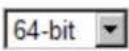
Key Length: select key length 64-bit or 128-bit.
Key Format:
Hexadecimal (WEP 64-bit): 10 Hex characters (0\~9, a\~f).
Hexadecimal (WEP 128-bit): 26 Hex characters (0\~9, a\~f).
ASCII (WEP 64-bit): 5 ASCII characters (case-sensitive).
ASCII (WEP 128-bit): 13 ASCII characters (case-sensitive).
Encryption Key: Enter the key in the key setting field.
802.1x Authentication
Encryption:

802.1×
Authentication:

Authentication:
Open System Shared Key Auto
Key Length:
64 Bits 128 Bits
RADIUS Server IP Address:

RADIUS Server Port:

RADIUS Server Password:

Key Length: select key length 64 Bits or 128 Bits.
RADIUS Server IP Address: Enter the RADIUS Server's IP Address provided by your ISP.
RADIUS Server Port: Enter the RADIUS Server's port number
provided by your ISP. The default is 1812.
RADIUS Server Password: Enter the password that the AP shares with the RADIUS Server.
WPA/ WPA2/ WPA2-Mixed
Encryption:
WPA-Mixed
Authentication Mode:
○ Enterprise (RADIUS) ◦ Personal (Pre-Shared Key)
WPA Cipher Suite:
TKIP AES
WPA2 Cipher Suite:
□TKIP ▼AES
Pre-Shared Key Format:
Passphrase
Pre-Shared Key:
Personal (Pre-Shared Key)
Authentication Mode: Select Enterprise (RADIUS) or Personal (Pre-Shared Key) mode.
WPA Cipher Suite: Here supported AES only.
WPA2 Cipher Suite: Here supported AES only.
Pre-Shared Key Format: There are two formats for choice to set the Pre-shared key, Passphrase and Hex (64 characters). If Hex is selected, users will have to enter a 64 characters string. For easier configuration, the Passphrase (at least 8 characters) format is recommended.
Pre-Shared Key : Pre-Shared Key serves as a password. Users may key in 8 to 63 characters string if you selected passphrase. Pre-shared key format to set the passwords or leave it blank, in which the 802.1x Authentication will be activated.
Make sure the same password is used on client's end.
Enterprise (RADIUS)
Encryption:
WPA-Mixed
Authentication
- Enterprise (RADIUS) - Personal (Pre-Shared
Mode:
Key)
WPA Cipher Suite:
□TKIP □AES
WPA2 Cipher Suite:
□TKIP □AES
RADIUS Server IP Address:

RADIUS Server Port:
1812
RADIUS Server Password:

RADIUS Server IP Address: Enter the RADIUS Server's IP Address provided by your ISP.
RADIUS Server Port: Enter the RADIUS Server's port number provided by your ISP. The default is 1812.
RADIUS Server Password: Enter the password that the AP shares with the RADIUS Server.
4.2.4 Access Control
Wireless Access Control Mode:
Disable

MAC Address:

Comment:

Apply Changes
Reset
Current Access Control List:
| MAC Address | Comment | Select |
| 12:34:56:78:90:00 |
| Wireless Access Control Mode | Enable or Disable the Access Control function. User can use this function for restricting the wireless client connection. |
| MAC Address | Enter the MAC address (12 characters) of a station that is allowed to access this Wireless Router. The format of the address should beXXXXXXXXXX. |
| Delete Selected Click | Delete Selected to delete items which are selected. |
| Delete All Click Delete | All to delete all the items. |
| Reset Click Reset to rest. | |
| Apply Change Click A | Apply Change for save the configuration. |
4.2.5 WDS Settings
Wireless Distribution System uses wireless media to communicate with other APs, like the Ethernet does. To do this, you must set these APs in the same channel and set MAC address of other APs which you want to communicate with in the table and then enable the WDS.
- The APs must support WDS function.
- The channel must be set to the same on the APs.
- To set the same Wireless MAC address (BSSID) on the APs.
- To set same security (WEP key) on the APs.
Note:
To setup WDS must use the same wireless products (the same model will be better); due to different wireless products might support different WDS settings.
Thus, it is suggested that to use the same wireless products that support WDS function.
Step1. Users would like to set up the WDS function, please go to Wireless → Basic Settings page to enable WDS function, and set the APs into the same Channel Number. After setting up, please click Apply Changes button to execute.
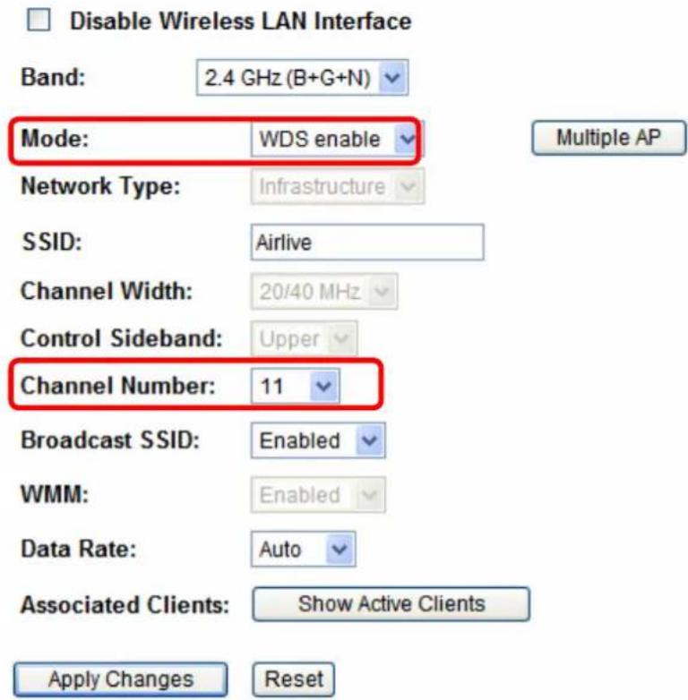
Step2. Then go back to Wireless WDS Settings page to enter the Wireless MAC address (please make sure the BSSID of the other WDS supported AP) 12 characters to each other to make the WDS connection. Please click Apply Changes button to execute.
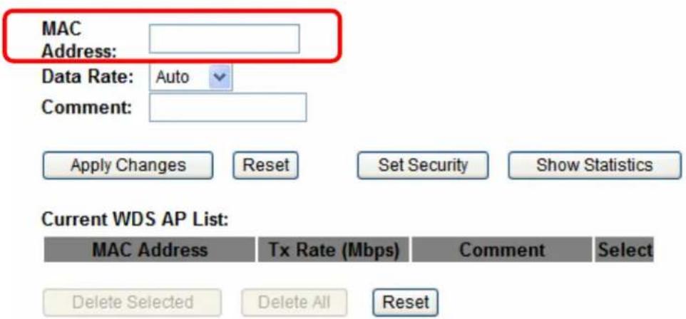
| MAC Address MAC Address: Enter the Wireless BSSID (MAC) 12 characters of the other wireless AP that you want to connect with. To check your wireless router's MAC address, please go to Status → Wireless Configuration to find your BSSID (Wireless MAC address.) | |
| System | |
| Uptime | 0day:0h:6m:36s |
| Firmware Version | 1.00e |
| Build Time | Mon Jul 18 20:50:11 CST 2011 |
| Wireless Configuration | |
| Mode | AP+WDS |
| Band | 2.4 GHz (B+G+N) |
| SSID | Airlive |
| Channel Number | 11 |
| Encryption | WPA2(AP), Disabled(WDS) |
| BSSID | 00:4f.6a:00:00:a2 |
| Associated Clients | 0 |
| Data Rate Select the data rate form the pull-down list. | |
| Comment Enter a description for the device. | |
| Apply Changes After completing the settings on this page, click Apply changes button to save the settings. | |
| Reset After completing the settings on this page, click Apply changes button to save the settings. | |
| Set Security | Enable the WDS function and then click Set Security button to set up the WDS security.Encryption: NoneWEP Key Format: ASCII (5 characters)WEP Key:Apply Changes ResetEncryption: Select the encryption type None, WEP 64 bits, WEP 128 bits from the pull-down menu.WEPThis page allows you setup the wireless security for WDS. When enabled, you must make sure each WDS device has adopted the same encryption algorithm and Key.Encryption: WEP 64bitsWEP Key Format: ASCII (5 characters)WEP Key: *****Apply Changes ResetWEP Key Format: For WEP 64 bits and WEP 128 bits encryption type, the selection of WEP Key Format are Hex and ASCII.WEP Key: If select Hex if you are using hexadecimal numbers (0-9, or A-F).Select ASCII if you are using ASCII characters (case-sensitive).Hexadecimal (WEP 64 bits): 10 Hex characters (0~9, a~f).Hexadecimal (WEP 128 bits): 26 Hex characters (0~9, a~f).ASCII (WEP 64 bits): 5 ASCII characters (case-sensitive).ASCII (WEP 128 bits): 13 ASCII characters (case-sensitive). |
Show Statistics Click Show Statistics to show the current WDS AP table. This table shows the MAC address, transmission packets and errors, reception packets and Tx Rate (Mbps) counters for each configured WDS AP.WDS AP TableThis table shows the MAC address, transmission, reception packet counters and state information for each configured WDS AP. Refresh CloseRefresh: Click to renew the counters information.Close: Click to leave the screen. Refresh CloseRefresh: Click to renew the counters information.Close: Click to leave the screen. | |
| Current WDS AP List | Here shows the current WDS AP information. |
| Delete Selected Click Delete Selected to delete the selected AP information. | |
| Delete All Click Delete All to delete all the items. | |
| Reset Click Reset to restore the settings. | |
4.2.6 Site Survey
This page provides tool to scan the wireless network. If any Access Point or IBSS is found, you could choose to connect it manually when client mode is enabled.
Site Survey
| SSID | BSSID | Channel | Type | Encrypt | Signal | Select |
| Costa | 06:4f:68:50:18:cf | 1 (B+G) | AP | WPA-PSK/WPA2-PSK | 68 | |
| Relax | 00:1f:1f:f3:cf:0e | 9 (B+G+N) | AP | WPA2-PSK | 48 |
Next>>
| Site Survey Check this button to renew all the listed access point. |
| Next Click the Next button to configure the security setting. |
Encryption: WPA2
Authentication Mode:
WPA2 Cipher Suite:
Pre-Shared Key Format:
Pre-Shared Key:
Previous
Finish
Personal (Pre-Shared Key)
□TKIP □AES
Passphrase


| Back Go back to previous step. |
| Connect Under the Repeater mode and select a site that you would like to communicate, and then click the Connect button to make a connection. |
4.2.7 WPS
WPS
This page allows you to change the setting for WPS (Wi-Fi Protected Setup). Using this feature could let your wireless client automatically synchronize its setting and connect to the Access Point in a minute without any hassle.
□ Disable WPS
Apply Changes
Reset
WPS Status:
Configured
UnConfigured
Reset to UnConfigured
Self-PIN Number:
42647508
Push Button Configuration:
Start PBC
Client PIN Number:
Start PIN
| Disable WPS Check the box to disable the WPS function, default setting is enabled. | |
| WPS Status Here shows the current status of the WPS function. Default setting is Configured, click Reset to UnConfigured to re-configured the WPS connection. | |
| Self-PIN Number | Here shows the 8-digit numbers PIN code of the router itself.Enter the Self-PIN Number to client (Registrar) end and click the PIN button at the client end to make a WPS connection. It will connect with the wireless router within two minutes and get IP address. |
| Push Button Configuration | Click Start PBC button (or press the physical WPS button on the Wireless Router once), meanwhile, the client should also click the PBC button simultaneously within 2 minutes. |
| Client PIN Number Enter the client (Enrollee) PIN code into the blank field then click the Start PIN button to make a WPS connection with client. Then, the wireless router will connect to client within 2 minutes and get IP address. | |
| Current Key Info | This table shows the security status of the Wireless Router. If user would like to set up the security, please go to Wireless > Security. |
4.2.8 Schedule
Schedule
This page allows you setup the wireless schedule rule. Please do not forget to configure system before enable this feature.
□ Enable Wireless Schedule
| Enable | Day | From | To | ||||||
| Sun | 00 | (hour) | 00 | (min) | 00 | (hour) | 00 | (min) | |
| Sun | 00 | (hour) | 00 | (min) | 00 | (hour) | 00 | (min) | |
| Sun | 00 | (hour) | 00 | (min) | 00 | (hour) | 00 | (min) | |
| Sun | 00 | (hour) | 00 | (min) | 00 | (hour) | 00 | (min) | |
| Sun | 00 | (hour) | (00) | (min) | 00 | (hour) | 00 | (min) | |
| Sun | 00 | (hour) | 00 | (min) | 00 | (hour) | 00 | (min) | |
| Sun | 00 | (hour) | 00 | (min) | 00 | (hour) | 00 | (min) | |
| Sun | 00 | (hour) | 00 | (min) | 00 | (hour) | 00 | ||
| Sun | 00 | (hour) | 00 | (min) | 00 | (hour) | 00 | (min) | |
| Sun | 00 | (hour) | 00 | (min) | 00 | (hour) | 00 | (min) | |
| Sun | 00 | (hour) | 00 | (min) | 00 | (hour) | 00 | (min) | |
| Sun | 00 | (hour) | 100 | (min) | 00 | (hour) | 00 | (min) | |

| Enable Wireless Schedule | Check the box to enable the schedule function. Set up the time to schedule the wireless access rule. Select the day and time you want to enable the wireless function. |
4.3 Internet Setting
4.3.1 WAN Interface
WAN Settings
This page is used to configure the parameters for Internet network which connects to the WAN port of your Access Point. Here you may change the access method to static IP, DHCP, PPPoE, PPTP, USB3G or L2TP by click the item value of WAN Access type.
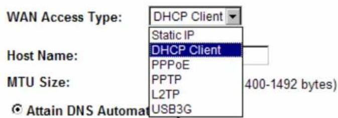
○ Set DNS Manually
WAN Connection Type
DHCP Client
WAN Access Type:
DHCP Client
Host Name:

MTU Size:
1492 (1400-1492 bytes)
If the DHCP Client connection be selected, the PC will obtain the IP address automatically.
Host Name: Enter the network area name in the column.
MTU Size: The most appropriate MTU (Maximum Transmission Unit) namely the maximum packet size, the default value is 1492 for your application. Reducing the packet size can help connecting to certain web sites or speeding up packet transfer rate. If the incorrect packet size is entered, you may not be able to open certain web sites.
Static IP
WAN Access Type:
Static IP

IP Address:
172.1.1.1
Subnet Mask:
255.255.255.0
Default Gateway:
172.1.1.254
MTU Size:
1500
(1400-1500 bytes)
DNS 1:
172.1.1.254
DNS 2:
168.95.1.1
DNS 3:
If the Static IP be selected, user have to set up the IP address, subnet mask and default gateway according to the ISP (Internet Service Provider) that provided the related information.
IP Address: Enter the WAN IP address provided by your ISP here.
Subnet Mask: Enter the subnet mask here. Default Gateway: Enter the default gateway IP address provided by your ISP here.
MTU Size: The most appropriate MTU (Maximum Transmission Unit) namely the maximum packet size. Reducing the packet size can help connecting to certain web sites or speeding up packet transfer rate. If the incorrect packet size is entered, you may not be able to open certain web sites.
DNS 1: Enter the DNS server IP address(es) provided by your ISP, or you can specify your own preferred DNS server IP address(es).
DNS 2/ DNS 3: These servers are optional. You can enter another DNS server's IP address as a backup. DNS 2 and 3 servers will be used when the DNS 1 server fails.
PPPoE
WAN Access Type:
PPPoE

User Name:
12345678@hinet.net
Password:

Service Name:
Connection Type:
Continuous

Connect
Disconnect
Idle Time:

(1-1000 minutes)
MTU Size:
1452
(1360-1492 bytes)

Attain DNS Automatically

Set DNS Manually
DNS 1:
172.1.1.254
DNS 2:
168.95.1.1
DNS 3:

If the PPPoE be selected, user has to set up the user name and password according to the ISP that provided the related information.
User Name: Enter the username that provide by your ISP provider. Maximum input is 32 alphanumeric characters (case sensitive).
Password: Enter the password that provide by your ISP provider. Maximum input is 32 alphanumeric characters (case sensitive).
Service Name: Enter the Internet service provider name in the column.
Connection Type: Select the connection type Continuous, Connect on Demand or Manual from the pull-down menu. If selected Manual user can click Connect button to make a connection.
Idle Time: It represents that the device will idle after the minutes you set. The time must be set between 1\~1000 minutes. Default value of idle time is 5 minutes. This function will be available when the Connection Type is selected to Connect on Demand.
MTU Size: The most appropriate MTU (Maximum Transmission Unit) namely the maximum packet size, the default value is 1452 for your application. Reducing the packet size can help connecting to certain web sites or speeding up packet transfer rate. If the incorrect packet size is entered, you may not be able to open certain web sites.
PPTP
WAN Access Type:

IP Address:
172.1.1.2
Subnet Mask:
255.255.255.0
Server IP Address:
172.1.1.1
User Name:
Password:
Connection Type:
Continuous

Connect
Disconnect
Idle Time:
5
(1-1000 minutes)
MTU Size:
1460
(1400-1460 bytes)

Request MPPE Encryption

Request MPPC Compression

Attain DNS Automatically

Set DNS Manually
DNS 1:
172.1.1.254
DNS 2:
168.95.1.1
DNS 3:
The Ground Truth image displays a single, solid horizontal line. According to Rule 2 (UNDERSCORE & LINE RULES), this is a stylistic or background line, not a placeholder underscore. Therefore, the OCR result must ignore it and output nothing or only meaningful text. The provided OCR content is "____", which consists of four underscores. This is an incorrect interpretation of the line as a placeholder, violating the rule that stylistic lines must be ignored. The OCR has hallucinated underscores where none should exist based on the GT's visual context. Hence, the OCR result is inconsistent with the Ground Truth.
If the PPTP be selected, user has to set up the server IP address, user name and password according to the ISP that provided the related information.
IP Address: Enter the WAN IP address provided by your ISP here.
Subnet Mask: Enter the subnet mask here.
Server IP Address: Enter the PPTP Server IP Address in this column.
User Name: Maximum input is 20 alphanumeric characters (case sensitive).
Password: Maximum input is 32 alphanumeric characters (case sensitive).
Connection Type: Select the connection type Continuous, Connect on Demand or Manual from the pull-down menu. If selected Manual user can click Connect button to make a connection.
Idle Time: It represents that the device will idle after the minutes you set. The time must be set between 1\~1000 minutes. Default value of idle time is 5 minutes. This function will be available when the Connection Type is selected to Connect on Demand.
MTU Size: The most appropriate MTU (Maximum Transmission Unit) namely the maximum packet size, the default value is 1460 for your application. Reducing the packet size can help connecting to certain web sites or speeding up packet transfer rate. If the incorrect packet size is entered, you may not be able to open certain web sites.
L2TP
WAN Access Type:
L2TP

IP Address:
172.1.1.2
Subnet Mask:
255.255.255.0
Server IP Address:
172.1.1.1
User Name:
Password:
Connection Type:
Continuous

Connect
Disconnect
Idle Time:
5
(1-1000 minutes)
MTU Size:
1460
(1400-1460 bytes)
Attain DNS Automatically
○ Set DNS Manually
DNS 1:
172.1.1.254
DNS 2:
168.95.1.1
DNS 3:
If the L2TP be selected, user has to set up the server IP address, user name and password according to the ISP that provided the related information.
IP Address: Enter the WAN IP address provided by your ISP here.
Subnet Mask: Enter the subnet mask here.
Server IP Address: Enter the L2TP Server IP Address in this column.
User Name: Maximum input is 20 alphanumeric characters (case
| sensitive).Password: Maximum input is 32 alphanumeric characters (case sensitive).Connection Type: Select the connection type Continuous, Connect on Demand or Manual from the pull-down menu. If selected Manual user can click Connect button to make a connection.Idle Time: It represents that the device will idle after the minutes you set. The time must be set between 1~1000 minutes. Default value of idle time is 5 minutes. This function will be available when the Connection Type is selected to Connect on Demand.MTU Size: The most appropriate MTU (Maximum Transmission Unit) namely the maximum packet size, the default value is 1460 for your application. Reducing the packet size can help connecting to certain web sites or speeding up packet transfer rate. If the incorrect packet size is entered, you may not be able to open certain web sites.3G:If the 3G be selected, user has to set up the user name, password and other information that the 3G connection needed.WAN Access Type: USB3GCountry: TaiwanISP: Chunghwa Telekom-AUser Name:Password:PIN:APN: emomeDial Number:Connection Type: Continuous Connect DisconnectIdle Time: 0 (1-1000 minutes)MTU Size: 1490 (1420-1490 bytes)Attain DNS AutomaticallySet DNS ManuallyDNS 1: 172.1.1.254DNS 2: 168.95.1.1DNS 3: | |
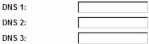
| ● Attain DNS Automatically● Set DNS Manually● DNS 1● DNS 2● DNS3 | Select to Attain DNS Automatically or select Set DNS Manually to set the DNS server IP address at the following DNS 1~3 columns. Default setting is Attain DNS Automatically.Enter the DNS server IP address(es) provided by your ISP, or you can specify your own preferred DNS server IP address(es).DNS 2 server is optional. You can enter another DNS server's IP address as a backup. DNS 2 server will be used when the DNS 1 server fails. |
| Clone MAC address | Your ISP may require a particular MAC address in order for you to connect to the Internet. This MAC address is the PC's MAC address that your ISP had originally connected your Internet connection to. Type in this Clone MAC address in this section to replace the WAN MAC address with the MAC address of that PC. |
| Enable uPNP... Check to enable the listed functions. | |
| Apply Changes After | completing the settings on this page, click Apply changes button to save the settings. |
| Reset Click Reset to | restore to default values. |
4.3.2 Port Filtering
Port Filtering
Entries in this table are used to restrict certain types of data packets from your local network to Internet through the Gateway. Use of such filters can be helpful in securing or restricting your local network.

Enable Port Filtering

Apply Changes
Reset
Current Filter Table:
Port Range
Protocol
Comment
Select
Delete Selected
Delete All
Reset
| Enable Port Filtering Check to enable Port Filtering function. | |
| Port Range Enter the beginning of the range of port numbers used by the service. If the service uses a single port number, enter it in both the start and finish fields. | |
| Protocol Select the protocol (TCP, UDP or Both) used to the remote system or service. | |
| Comment You may key in a description MAC address. | |
| Apply Changes After completing the settings on this page, click Apply Changes button to save the settings. | |
| Reset Click Reset button to restore to default values. | |
| Current Filter Table Shows the current Port Forwarding information. | |
| Delete Selected Click Delete Selected button to delete items which are selected. | |
| Delete All Click Delete All button to delete all the items. | |
| Reset Click Reset button to rest. |
4.3.3 IP Filtering
IP Filtering
Entries in this table are used to restrict certain types of data packets from your local network to Internet through the Gateway. Use of such filters can be helpful in securing or restricting your local network.
□ Enable IP Filtering
LoaIP Address: Protocol: Both Comment:
Apply Changes Reset
Current Filter Table:
Local IP Address Protocol Comment Select
Delete Selected Delete All Reset
| Enable IP Filtering Check to enable IP filtering function. | |
| Local IP Address Enter the local computer's IP address. | |
| Protocol Select the protocol (TCP, UDP or Both) used to the remote system or service. | |
| Comment You may key in a description for the port range. | |
| Apply Changes After completing the settings on this page, click Apply Changes button to save the settings. | |
| Reset Click Reset button to restore to default values. | |
| Current Filter Table Shows the current IP filter information. | |
| Delete Selected | Click Delete Selected button to delete items which are selected. |
| Delete All Click Delete | All button to delete all the items. |
| Reset Click Reset button to rest. | |
4.3.4 Port Forwarding
Port Forwarding
Entries in this table allow you to automatically redirect common network services to a specific machine behind the NAT firewall. These settings are only necessary if you wish to host some sort of server like a web server or mail server on the private local network behind your Gateway's NAT firewall.
□ Enable Port Forwarding
IP Address: ☐ Protocol: Both Port Range: ☐ Comment: ☐
Apply Changes Reset
Current Port Forwarding Table:
Local IP Address Protocol Port Range Comment Select Delete Selected Delete All Reset
| Enable Port Forwarding | Check to enable Port Forwarding function. |
| IP Address Enter the IP address in the field. | |
| Protocol Select the protocol (TCP, UDP or Both) used to the remote system or service. | |
| Port Range For TCP and UDP Services, enter the beginning of the range of port numbers used by the service. If the service uses a single port number, enter it in both the start and finish fields. | |
| Comment You may key in a description MAC address. | |
| Apply Changes After completing the settings on this page, click Apply Changes button to save the settings. | |
| Reset Click Reset button to restore to default values. | |
| Current Port Forwarding Table | Shows the current Port Forwarding information. |
| Delete Selected Click Delete Selected button to delete items which are selected. | |
| Delete All Click Delete All button to delete all the items. | |
| Reset Click Reset button to rest. | |
4.3.5 URL Filtering
URL Filtering
URL filter is used to deny LAN users from accessing the internet. Block those URLs which contain keywords listed below.

Enable URL Filtering
URL Address:
Apply Changes
Reset
Current Filter Table:
URL Address
Select
Delete Selected
Delete All
Reset
| Enable URL Filtering | Check to enable URL filtering function. |
| URL Address Enter the | URL address in the field |
| Apply Changes After | completing the settings on this page, click Apply Changes button to save the settings. |
| Reset Click Reset button to restore to default values. | |
| Current Filter Table Shows the current URL address filter information. | |
| Delete Selected Click Delete All button to delete all the items. | |
| Reset Click Reset button to rest. | |
4.3.6 DMZ
DMZ
A Demilitarized Zone is used to provide Internet services without sacrificing unauthorized access to its local private network. Typically, the DMZ host contains devices accessible to Internet traffic, such as Web (HTTP) servers, FTP servers, SMTP (e-mail) servers and DNS servers.

Enable DMZ
DMZ Host IP Address:

Apply Changes
Reset
| Enable DMZ Check the box to enable DMZ function. If the DMZ Host Function is enabled, it means that you set up DMZ host at a particular computer to be exposed to the Internet so that some applications/software, especially Internet / online game can have two way connections. |
| DMZ Host IP Address Enter the IP address of a particular host in your LAN which will receive all the packets originally going to the WAN port/Public IP address above.NoteYou need to give your LAN PC clients a fixed/static IP address for DMZ to work properly. |
| Apply Changes After completing the settings on this page, click Apply Changes button to save the settings. |
| Reset Click Reset button to restore to default values |
4.3.7 DDNS
DDNS
Dynamic DNS is a service, that provides you with a valid, unchanging, internet domain name (an URL) to go with that (possibly everchanging) IP-address.

Enable DDNS
Service Provider :

Domain Name :
host.dyndns.org
User Name/Email:

Password/Key:

Note:
For TZO, you can have a 30 days free trial here or manage your TZO account in control panel. For DynDNS, you can create your DynDNS account here
Apply Change
Reset
| Enable DDNS Check to enable the DDNS function. | |
| Service Provider Select the desired DDNS Service Provider DynDNS or TZO from the pull-down list. | |
| Domain Name Here shows the domain name of the service provider. | |
| User Name/Email Enter your email that you registered in service provider website.(You can refer to below Note information to apply a account form the service provider website.) | |
| Password/Key Enter your passwords that you registered in service provider website. Maximum input is 30 alphanumeric characters (case sensitive). | |
| Apply Changes After completing the settings on this page, click Apply Changes button to save the settings. | |
| Reset Click Reset button to restore to default values. |
4.3.8 Router Setup
Route Setup
This page is used to setup dynamic routing protocol or edit static route entry.
□ Enable Dynamic Route
NAT:
Enabled
Disabled
Transmit:
- Disabled
RIP 1 RIP 2
Receive:
- Disabled
RIP 1 RIP 2
Apply Changes
Reset
□ Enable Static Route
IP Address:

Subnet Mask:

Gateway:

Metric:
Interface:

Apply Changes
Reset
Show Route Table
Static Route Table:
| Destination IP Address | Netmask | Gateway | Metric | Interface | Select |
Delete Selected
Delete All
Reset
| Enable Dynamic Route | Dynamic routing performs the same function as static routing except it is steadier. Dynamic routing allows routing tables in routers to change as the possible routes change. There are several protocols used to support dynamic routing including RIP and OSPF. |
| NAT Network Address | Translation (NAT) selects to enable or disable this function. |
| Transmit Select to enable or disable RIP protocol for transmit. | |
| Receive Select to enable or disable RIP protocol for receive. | |
| Enable Static Route If | you connect several routers with this Wireless Router, you may need to set up a predefined routing rule to have more effective network topology/traffic, this is called static route between those routers and the Wireless Router.To set static routers, enter the settings including route IP address, route mask, route gateway and the route Interface from LAN or WAN. |
| IP Address Set up the | IP address that would like to send the packets pass through. |
| Subnet Mask Set up the | Subnet Mask that would like to send the packets pass through. |
| Gateway Set up the | gateway that would like to send the packets pass through. |
| Metric It is used by a | router to make routing decisions.The metrics used by a router to make routing decisions. It is typically one of many fields in a routing table. Router metrics can contain any number of values that help the router determine the best route among multiple routes to a destination. A router metric typically based on information like path length, bandwidth, load, hop count, path cost, delay, Maximum Transmission Unit (MTU), reliability and communications cost. |
| Interface Select the int | interface of the setting path. |
4.4 System
4.4.1 LAN Interface
LAN Interface
This page is used to configure the parameters for local area network which connects to the LAN port of your Access Point. Here you may change the setting for IP address, subnet mask, DHCP, etc..
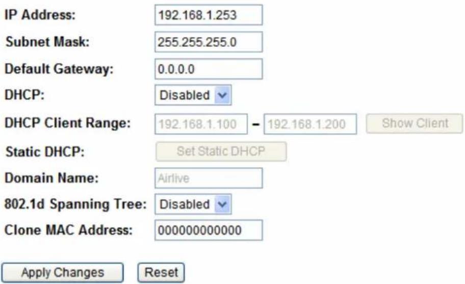
| IP Address | Shows the IP address of the Wireless Router. Default IP address is 192.168.1.254 (Router/AP mode) or 192.168.1.253 (Client Mode). |
| Subnet Mask | The subnet mask of the Wireless Router (Default subnet mask is 255.255.255.0.) |
| Default Gateway | Enter the Gateway IP address here. |
| DHCP | Disable: Select to disable this Wireless Router to distribute IP addresses to connected clients.Server: Select to enable this Wireless Router to distribute IP Addresses (DHCP Server) to connected clients. And the following field will be activated for you to enter the starting IP address. |
| DHCP Client Range | The starting address of this local IP network address pool. The pool is a piece of continuous IP address segment, the device will distribute IP addresses from 192.168.1.100 to 192.168.1.200 to all the computers in the network that request IP addresses from DHCP server (Router). The end IP address maximum is 253.Note:If “Continuous IP address pool starts” is set at 192.168.1.1 and the “Number of IP address in pool end” is 253, the device will distribute IP addresses from 192.168.1.100 to 192.168.1.253 to all the computers in the network that request IP addresses from DHCP server (Router).Click Show Client button to show Active DHCP Client Table. The table shows assigned IP address, MAC address and time expired for each client.Active DHCP Client TableThis table shows the assigned IP address, MAC address and time expired for each DHCP leased client. Refresh CloseRefresh: Click this button to refresh the table.Close: Click this button to close the window. Refresh CloseRefresh: Click this button to refresh the table.Close: Click this button to close the window. |
| Static DHCP | Check the box to enable the Static DHCP function, default setting is disabled.When set to enabled, user can click Set Static DHCP button to set the Static DHCP function.Static DHCP SetupThis page allows you reserve IP addresses, and assign the same IP address to the network device with t any time it requests an IP address. This is almost the same as when a device has a static IP address exce request an IP address from the DHCP server.Enable Static DHCPIP Address: MAC Address:  Comment: Apply Changes ResetStatic DHCP List: Comment: Apply Changes ResetStatic DHCP List: IP Address: Enter the fixed IP address that DHCP server assigned to a certain connected station.MAC Address: Enter the MAC address of a certain station, and then the DHCP server will to distribute a fixed IP address to the station automatically once they connected.Comment: You can enter a comment to description above IP address or MAC address.Apply Changes: After completing the settings on this page, click Apply changes button to save the settings.Reset: Click Reset to restore to default values.Static DHCP List: Here shows the static IP address that have been assigned according to the MAC address.Delete Selected: Click Delete Selected to delete items which are selected.Delete All: Click Delete All button to delete all the items.Reset: Click Reset button to rest. IP Address: Enter the fixed IP address that DHCP server assigned to a certain connected station.MAC Address: Enter the MAC address of a certain station, and then the DHCP server will to distribute a fixed IP address to the station automatically once they connected.Comment: You can enter a comment to description above IP address or MAC address.Apply Changes: After completing the settings on this page, click Apply changes button to save the settings.Reset: Click Reset to restore to default values.Static DHCP List: Here shows the static IP address that have been assigned according to the MAC address.Delete Selected: Click Delete Selected to delete items which are selected.Delete All: Click Delete All button to delete all the items.Reset: Click Reset button to rest. |
| Domain Name Enter the network area name here. | |
| 802.1d Spanning Tree | Select Disabled or Enabled form the pull-down list. |
Static DHCP Setup
| Clone MAC Address | Your ISP may require a particular MAC address in order for you to connect to the Internet. This MAC address is the PC’s MAC address that your ISP had originally connected your Internet connection to. Type in the MAC address to replace the WAN MAC address with the MAC address of that PC. |
4.4.2 Time Zone Setting
Time Zone Settings
You can maintain the system time by synchronizing with a public time server over the Internet.

□ Enable NTP client update
□ Automatically Adjust Daylight Saving
NTP server :

Apply Change
Reset
Refresh
| Current Time | Enter the current time of this wireless router or click the Copy Computer Time button to synchronize the time with the connected computer automatically. |
| Time Zone Select | Select the local time zone from the pull-down menu. |
| Enable NTP client update | Check to enable NTP (Network Time Protocol Server) client update function. |
| Automatically Adjust Daylight Saving | Check the box to enable this function. |
| NTP server ManualIP Setting | You may choose to select NTP server from the pull-down menu or enter an IP address of a specific server manually. |
| Apply Changes After | completing the settings on this page, click Apply Changes button to save current settings. |
| Refresh Click Refresh | button to renew current time. |
4.4.3 Denial-of-Service
Denial-of-Service
A "denial-of-service" (DoS) attack is characterized by an explicit attempt by hackers to prevent legitimate users of a service from using that service.
□ Enable DoS Prevention
Whole System Flood: SYN
Whole System Flood: FIN
Whole System Flood: UDP
Whole System Flood: ICMP
☐ Per-Source IP Flood: SYN
☐ Per-Source IP Flood: FIN
☐ Per-Source IP Flood: UDP
☐ Per-Source IP Flood: ICMP
TCP/UDP PortScan
0 Packets/Second
0 Packets/Second
0 Packets/Second
0 Packets/Second
0 Packets/Second
0 Packets/Second
0 Packets/Second
Low Sensitivity
ICMP Smurf
IP Land
IP Spoof
IP TearDrop
□ PingOfDeath
TCP Scan
TCP SynWithData
□ UDP Bomb
□ UDP EchoChargen
Select ALL
Clear ALL
□ Enable Source IP Blocking
0 Block time (sec)
Apply Changes
| Enable DoS Prevention | DoS (Denial of Service) attacks can flood your Internet connection with invalid packets and connection requests, using so much bandwidth and so many resources that Internet access becomes unavailable. The Wireless Router incorporates protection against DoS attacks. This screen allows you to configure DoS protection. Check the box to enable the DoS settings. |
| Select All After you enabled the DoS prevention, you can click to select all DoS preventions. |
| Clear All After you enabled the DoS prevention, you can click to uncheck all DoS preventions. |
| Apply Changes After completing the settings on this page, click Apply Changes button to save current settings. |
4.4.4 Upgrade Firmware
Upgrade Firmware
This page allows you upgrade the Access Point firmware to new version. Please note, do not power off the device during the upload because it may crash the system.
Firmware Version:
Select File:
1.00e

Upload
Reset
| Select File Click the | Browse button to find and open the firmware file (the browser will display to correct file path.) |
| Upload Click the Upload | button to perform. |
| Reset Click Reset button | to restore to default values. |
4.4.5 Save/Reload Setting
Save/Reload Setting
This page allows you save current settings to a file or reload the settings from the file which was saved previously. Besides, you could reset the current configuration to factory default.
Save Settings to File:
Save...
Load Settings from File:
Browse
Upload
Reset Settings to Default:
Reset
| Save Settings to File | Click the Save button to save the current settings file in the PC. |
| Load Settings form File | Click the Browse button to find and open the previous saved file (the browser will display to correct file path.) Then, click Upload button to upload the previous file. |
| Reset Settings to Default | Click Reset button to set the device back to default settings. |
4.4.6 Password
Password
This page is used to set the account to access the web server of Access Point. Empty user name and password will disable the protection.
User Name:

New Password:

Confirmed Password:

Apply Changes
Reset
| User Name Key in a new login user name in the blank field. User can empty the user name and password columns to disable the access. |
| New Password Maximum input is 30 alphanumeric characters (case sensitive.) |
Confirmed Password Key in the password again to confirm.
4.4.7 QoS
QoS
Entries in this table improve your online gaming experience by ensuring that your game traffic is prioritized over other network traffic, such as FTP or Web.
Enable QoS
√ Automatic Uplink Speed
Manual Uplink Speed (Kbps): 512
√ Automatic Downlink Speed
Manual Downlink Speed (Kbps): 512
QoS Rule Setting:
Address Type:
Local IP Address:
MAC Address:
Mode:
Uplink Bandwidth (Kbps):
Downlink Bandwidth (Kbps):
Comment:
Apply Changes
Reset
IP MAC


Guaranteed minimum bandwidth


Current QoS Rules Table:
Local IP Address
MAC Address
Mode
Uplink Bandwidth
Downlink Bandwidth
Comment
Select
Delete Selected
Delete All
Reset
| Enable QoS This function improves online gaming experience by ensuring that game traffic is prioritized over other network traffic, such as FTP or Web. | |
| Automatic Uplink/Download Speed | Check the box to enable the automatic uplink/ download speed function. |
| Manual Uplink/Download Speed | You can manually enter the uplink/ download transmission rate in the blank field. |
| Address Type Select IP or MAC address type. | |
| Local IP address MAC address | Depend on the address type that selected, user can enter the IP address or MAC address of client to set up the bandwidth of the transmission. |
| Mode Select Guaranteed minimum bandwidth or Restricted maximum bandwidth modes. | |
| Uplink Bandwidth (Kbps) | Enter the Uplink Bandwidth (Kbps) in the column. |
| Downlink Bandwidth (Kbps) | Enter the Downlink Bandwidth (Kbps) in the column. |
| Comment Enter the note for the setting. | |
4.5 Ststus
4.5.1 Status
User can check the running information about N.Plug in this page.
Status
This page shows the current status and some basic settings of the device.
| System | |
| Uptime | 0day:0h:28m:26s |
| Firmware Version | 1.00e |
| Build Time | Mon Jul 18 20:50:11 CST 2011 |
| Wireless Configuration | |
| Mode | AP+WDS |
| Band | 2.4 GHz (B+G+N) |
| SSID | Airlive |
| Channel Number | 11 |
| Encryption | WPA2(AP), Disabled(WDS) |
| BSSID | 00:4f:6a:00:00:a2 |
| Associated Clients | 0 |
| TCP/IP Configuration | |
| Attain IP Protocol | Fixed IP |
| IP Address | 192.168.1.253 |
| Subnet Mask | 255.255.255.0 |
| Default Gateway | 0.0.0.0 |
| DHCP Server | Disabled |
| MAC Address | 00:4f:6a:00:00:a2 |
| WAN Configuration | |
| Attain IP Protocol | Getting IP from DHCP server... |
| IP Address | 0.0.0.0 |
| Subnet Mask | 0.0.0.0 |
| Default Gateway | 0.0.0.0 |
| MAC Address | 00:4f:6a:00:00:a3 |
4.5.2 Statistics
User can check the wireless connection information in this page.
Statistic
This page shows the packet counters for transmission and reception regarding to wireless and Ethernet networks.
| Wireless LAN | Sent Packets | 311 |
| Received Packets | 15389 | |
| Ethernet LAN | Sent Packets | 7327 |
| Received Packets | 5487 | |
| Ethernet WAN | Sent Packets | 0 |
| Received Packets | 0 |
Refresh
4.5.3 Log
User can check the system log in this page.
Log
This page can be used to set remote log server and show the system log.
Enable Log
□ system all
□ wireless
DoS
□ Enable Remote Log
Log Server IP Address:

Apply Changes
Refresh
Clear
4.6 Reboot
User can reboot the N.Plug by clicking the Reboot button.
Reboot
In the event that the system stops responding correctly or stops functioning, you can perform a Reboot. Your settings will not be changed. To perform the reboot, click on the APPLY button below. You will be asked to confirm your decision. The Reboot will be complete when the LED Power light stops blinking.
Reboot
5
PC Configuration
5.1 Overview
For each PC, the following may need to be configured:
- TCP/IP network settings
- Internet Access configuration
● Wireless configuration
5.2 Windows Clients
- This section describes how to configure Windows clients for Internet access via the Wireless Router.
● The first step is to check the PC's TCP/IP settings. - The Wireless Router uses the TCP/IP network protocol for all functions, so it is essential that the TCP/IP protocol be installed and configured on each PC.
5.2.1 TCP/IP Settings – Overview
If using default Wireless Router settings, and default Windows TCP/IP settings, no changes need to be made.
- By default, the Wireless Router will act as a DHCP Server, automatically providing a suitable IP address (and related information) to each PC when the PC boots.
- For all non-Server versions of Windows, the default TCP/IP setting is to act as a DHCP client.
If using a Fixed (specified) IP address, the following changes are required:
● The Gateway must be set to the IP address of the Wireless Router.
● The DNS should be set to the address provided by your ISP.
5.2.2 Checking TCP/IP Settings - Windows 2000
- Select Control Panel - Network and Dial-up Connection.
- Right - click the Local Area Connection icon and select Properties. You should see a screen like the following:
![Local Area Connection Properties General Connect using: SMC EZ Card 10/100 (SMC1211TX) Configure Components checked are used by this connection: Client for Microsoft Networks File and Printer Sharing for Microsoft Networks Internet Protocol [TCP/IP] Install... Uninstall Properties Description Transmission Control Protocol/Internet Protocol. The default wide area network protocol that provides communication across diverse interconnected networks. Show icon in taskbar when connected OK Cancel](/content/2026/05/758248/images/ca12bd1d906c6f91e0e27cbb50752f86d523fd7a9d6f6aaf9ddd8698d9fd7723.jpg)
-
Select the TCP/IP protocol for your network card.
-
Click on the Properties button. You should then see a screen like the following.
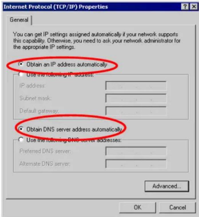
Ensure your TCP/IP settings are correct, as described below.
Using DHCP
- To use DHCP, select the radio button Obtain an IP Address automatically. This is the default Windows setting. Using this is recommended. By default, the Wireless Router will act as a DHCP Server.
- Restart your PC to ensure it obtains an IP Address from the Wireless Router.
Using a fixed IP Address ("Use the following IP Address") If your PC is already configured, check with your network administrator before making the following changes.
- Enter the Wireless Router's IP address in the Default gateway field and click OK. (Your LAN administrator can advise you of the IP Address they assigned to the Wireless Router.)
- If the DNS Server fields are empty, select Use the following DNS server addresses, and enters the DNS address or addresses provided by your ISP, then click OK.
5.2.3 Checking TCP/IP Settings - Windows XP
- Select Control Panel - Network Connection.
- Right click the Local Area Connection and choose Properties. You should see a screen like the following:
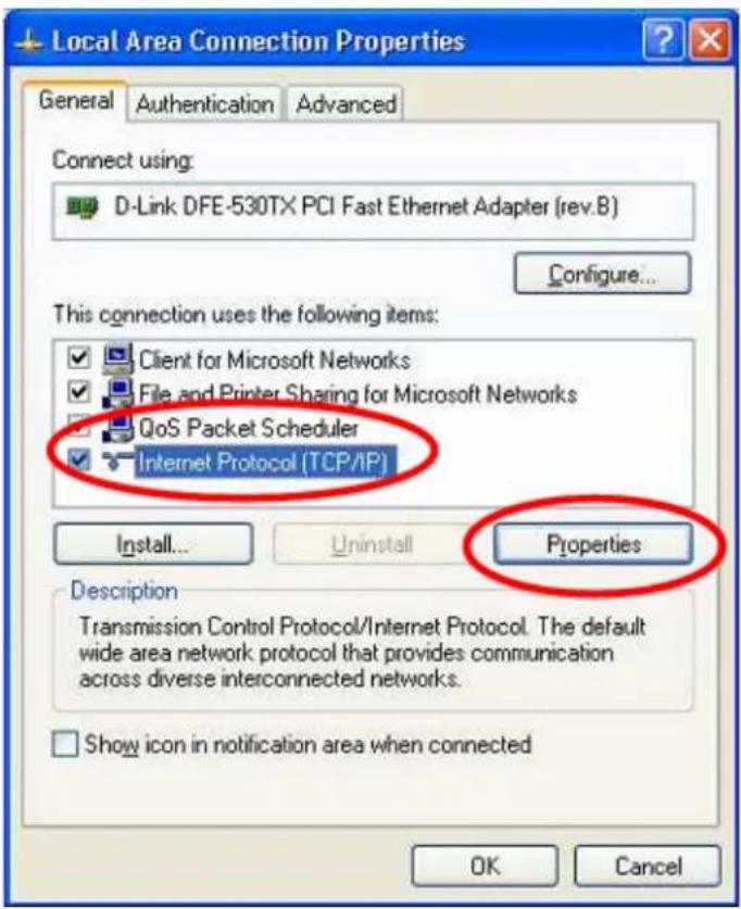
- Select the TCP/IP protocol for your network card.
- Click on the Properties button. You should then see a screen like the following.
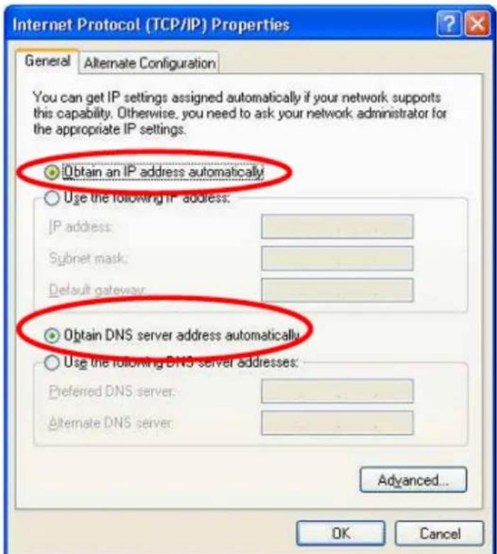
- Ensure your TCP/IP settings are correct.
Using DHCP
- To use DHCP, select the radio button Obtain an IP Address automatically. This is the default Windows setting. Using this is recommended. By default, the Wireless Router will act as a DHCP Server.
- Restart your PC to ensure it obtains an IP address from the Wireless Router.
Using a fixed IP Address ("Use the following IP Address")
If your PC is already configured, check with your network administrator before making the following changes.
- In the Default gateway field, enter the Wireless Router's IP address and click OK. Your LAN administrator can advise you of the IP Address they assigned to the Wireless Router.
- If the DNS Server fields are empty, select Use the following DNS server addresses, and enters the DNS address or addresses provided by your ISP, then click OK.
5.2.4 Checking TCP/IP Settings - Windows Vista
- Go to Start > Control Panel> Network and Internet> Network and Sharing Center> Manage Network Connections> Local Area Connection.
- Right click the Local Area Connection icon and choose Properties. You should see a screen like the following:
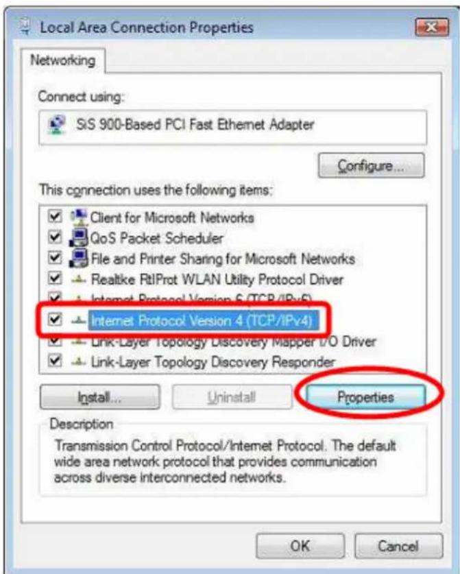
-
Select the Internet Protocol Version 4(TCP/IPv4) or 6 (TCP/IPv6) for your network card.
-
Click on the Properties button. You should then see a screen like the following.
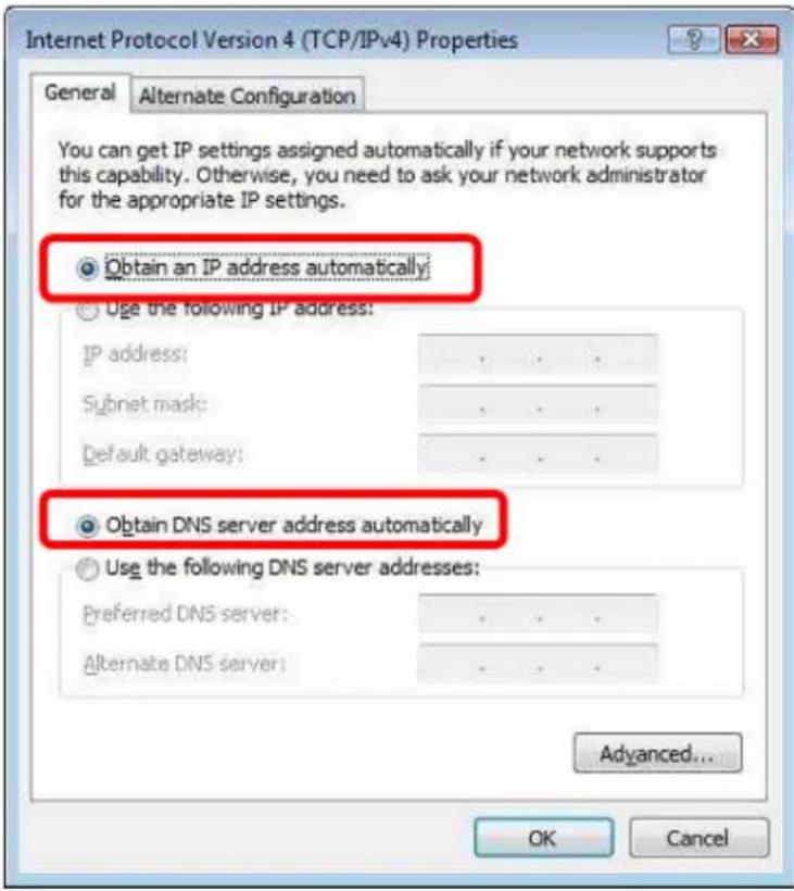
- Ensure your TCP/IP settings are correct.
Using DHCP
- To use DHCP, select Obtain an IP address automatically and Obtain DNS server address automatically. This is the default Windows setting. Using this is recommended. By default, the Wireless Router will act as a DHCP Server.
- Restart your PC to ensure it obtains an IP address from the Wireless Router.
Using a fixed IP Address ("Use the following IP Address")
If your PC is already configured, check with your network administrator before making the following changes.
- In the Default gateway field, enter the Wireless Router's IP address. Your LAN administrator can advise you of the IP address they assigned to the Wireless Router.
- If the DNS Server fields are empty, select Use the following DNS server addresses, and enters the DNS address or addresses provided by your ISP, then click OK.
5.2.5 Checking TCP/IP Settings - Windows 7
- Go to Start > Control Panel> Network and Sharing Center> Manage Network Connections> Local Area Connection.
- Right click the Local Area Connection icon and choose Properties. You should see a screen like the following:
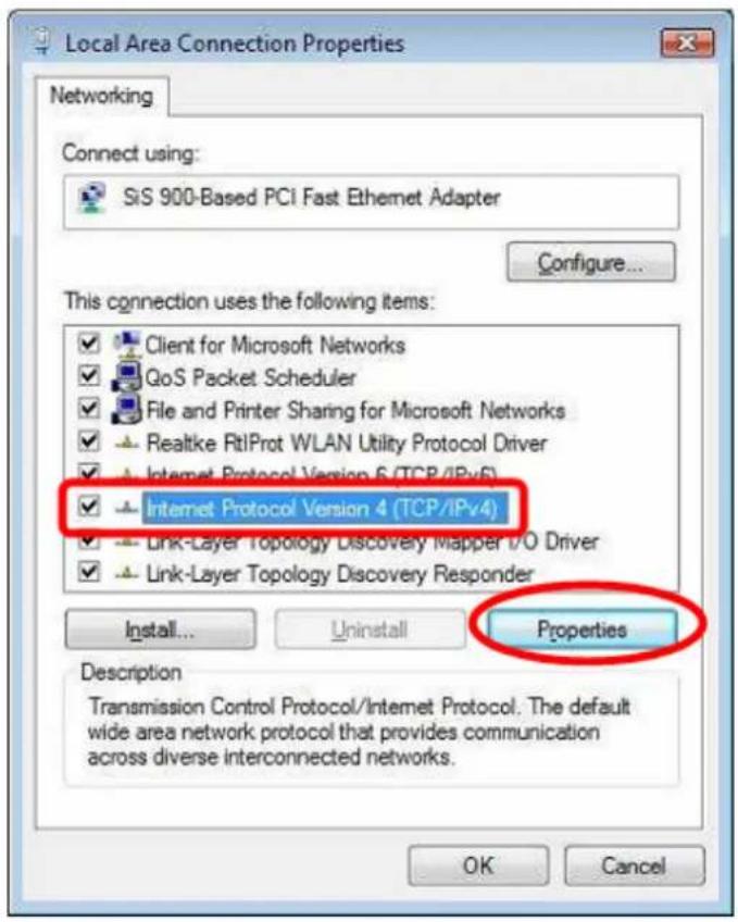
-
Select the Internet Protocol Version 4(TCP/IPv4) or 6 (TCP/IPv6) for your network card.
-
Click on the Properties button. You should then see a screen like the following.
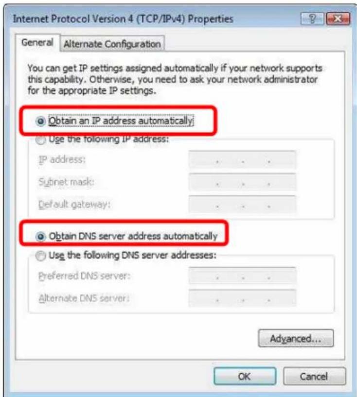
Using DHCP
- To use DHCP, select Obtain an IP address automatically and Obtain DNS server address automatically. This is the default Windows setting. Using this is recommended. By default, the Wireless Router will act as a DHCP Server.
- Restart your PC to ensure it obtains an IP address from the Wireless Router.
Using a fixed IP Address ("Use the following IP Address")
If your PC is already configured, check with your network administrator before making the following changes.
- In the Default gateway field, enter the Wireless Router's IP address. Your LAN administrator can advise you of the IP address they assigned to the Wireless Router.
- If the DNS Server fields are empty, select Use the following DNS server addresses, and enters the DNS address or addresses provided by your ISP, then click OK.
5.2.6 Internet Access
To configure your PCs to use the Wireless Router for Internet access:
- Ensure that the ADSL modem, DSL modem, Cable modem, or other permanent connection is functional.
- Use the following procedure to configure your Browser to access the Internet via the LAN, rather than by a Dial-up connection.
For Windows 2000
- Select Start menu - Settings - Control Panel - Internet Options.
- Select the Connection tab, and click the Setup button.
- Select "I want to set up my Internet connection manually, or I want to connect through a local area network (LAN)" and click Next.
- Select "I connect through a local area network (LAN)" and click Next.
- Ensure all of the boxes on the following Local area network Internet Configuration screen are unchecked.
- Check the "No" option when prompted "Do you want to set up an Internet mail account now?"
- Click Finish to close the Internet Connection Wizard. Setup is now completed.
For Windows XP
- Select Start menu >Control Panel > Network and Internet Connections.
- Select Set up or change your Internet Connection.
- Select the Connection tab, and click the Setup button.
- Cancel the pop-up "Location Information" screen.
- Click Next on the "New Connection Wizard" screen.
- Select "Connect to the Internet" and click Next.
For Windows Vista
- Select Start menu > Control Panel > Network and Internet> Network and Sharing Center.
-
Select Set up a connection or network.
-
Select Connect to the Internet and click Next to continue.
- Select Broadband (PPPoE).
- Enter User name and Password that provided by the ISP, then click Connect to make a connection.
For Windows 7
- Select Start menu > Control Panel > Network Sharing Center.
- Select Set up a new connection or network.
- Select Connect to the Internet and click Next to continue.
- Select Broadband (PPPoE).
- Enter User name and Password that provided by the ISP, then click Connect to make a connection.
Accessing AOL
To access AOL (America On Line) through the Wireless Router, the AOL for Windows software must be configured to use TCP/IP network access, rather than a dial-up connection. The configuration process is as follows:
- Start the AOL for Windows communication software. Ensure that it is Version 2.5, 3.0 or later. This procedure will not work with earlier versions.
- Click the Setup button.
- Select Create Location, and change the location name from "New Locality" to "Wireless Router".
- Click Edit Location. Select TCP/IP for the Network field. (Leave the Phone Number blank.)
- Click Save, then OK.
- Configuration is now complete.
- Before clicking "Sign On", always ensure that you are using the "Wireless Router" location.
5.2.7 Macintosh Clients
From your Macintosh, you can access the Internet via the Wireless Router. The procedure is as follow
- Open the TCP/IP Control Panel.
- Select Ethernet from the Connect via pop-up menu.
- Select Using DHCP Server from the Configure pop-up menu. The DHCP Client ID field can be left blank.
- Close the TCP/IP panel, saving your settings.
Note
If using manually assigned IP addresses instead of DHCP, the required changes are:
- Set the Router Address field to the Wireless Router's IP Address.
- Ensure your DNS settings are correct.
5.2.8 Linux Clients
To access the Internet via the Wireless Router, it is only necessary to set the Wireless Router as the "Gateway".
Ensure you are logged in as "root" before attempting any changes.
Fixed IP Address
By default, most Unix installations use a fixed IP Address. If you wish to continue using a fixed IP Address, make the following changes to your configuration.
- Set your "Default Gateway" to the IP Address of the Wireless Router.
- Ensure your DNS (Domain Name server) settings are correct.
To act as a DHCP Client (Recommended)
The procedure below may vary according to your version of Linux and X-windows shell.
- Start your X Windows client.
- Select Control Panel – Network.
- Select the "Interface" entry for your Network card. Normally, this will be called "eth0".
-
Click the Edit button, set the "protocol" to "DHCP", and save this data.
-
To apply your changes:
-
Use the "Deactivate" and "Activate" buttons, if available.
- OR, restart your system.
5.2.9 Other Unix Systems
To access the Internet via the Wireless Router:
- Ensure the "Gateway" field for your network card is set to the IP Address of the Wireless Router.
- Ensure your DNS (Name Server) settings are correct.
5.2.10 Wireless Station Configuration
- This section applies to all wireless stations wishing to use the Wireless Router's access point, regardless of the operating system that is used on the client.
- To use the Wireless Router, each wireless station must have compatible settings, as following:
| Mode The mode must be set to Infrastructure. | |
| SSID (ESSID) The network name must match the value used on the Wireless Router.NoteThe SSID is case- sensitive. | |
| Disable If there is no security is enabled on the Wireless Router, the security of each station should be disabled as well. And, you can connect the Wireless Router without security, but it is NOT recommended. | |
| WEP By default, WEP on the Wireless Router is disabled.If WEP remains disabled on the Wireless Router, all stations must have WEP disabled.If WEP is enabled on the Wireless Router, each station must use the same settings as the Wireless Router. | |
| WPA | RADIUS Server: RADIUS is an authentication, authorization and accounting client-server protocol. The client is a Network Access Server that desires to authenticate its links. The server is a server that has access to a user database with authentication information. Each station must set up the RADIUS Server's IP address, port and passwords that provided by your ISP. |
| WPA2 | |
| WPA-Mixed | |
| 802.1x | |
Note
By default, the Wireless Router will allow 802.11b, 802.11g and 802.11n connection
A
Appendix A: Troubleshooting
Overview
This chapter covers some common problems that may be encountered while using the Wireless Router and some possible solutions to them. If you follow the suggested steps and the Wireless Router still does not function properly, contact your dealer for further advice.
General Problems
| Problem 1: | Can't connect to the Wireless Router to configure it. |
| Solution 1: Check the following:Check the Wireless Router is properly installed, LAN connections are OK, and it is powered ON.Ensure that your PC and the Wireless Router are on the same network segment.If your PC is set to "Obtain an IP Address automatically" (DHCP client), please restart it.If your PC uses a Fixed (Static) IP address, ensure that it is using an IP Addresswithin the range 192.168.1.1 to 192.168.1.253 and thus compatible with the Wireless Router's default IP Address of 192.168.1.253.Also, the Network Mask should be set to 255.255.255.0 to match the Wireless Router.In Windows, you can check these settings by using Control Panel-Network to check the Properties for the TCP/IP protocol. | |
Internet Access
| Problem 1: When I enter a URL or IP address I get a time out error. | |
| Solution 1: A number of things could be causing this. Try the following troubleshooting steps.Check if other PCs work. If they do, ensure that your PCs IP settings are correct. If using a Fixed (Static) IP Address, check the Network Mask, Default gateway and DNS as well as the IP Address.If the PCs are configured correctly, but still not working, check the Wireless Router. Ensure that it is connected and ON. Connect to it and check its settings. (If you can't connect to it, check the LAN and power connections.)If the Wireless Router is configured correctly, check your Internet connection (DSL/Cable modem etc) to see that it is working correctly. | |
| Problem 2: Some applications do not run properly when using the Wireless Router. | |
| Solution 2: The Wireless Router processes the data passing through it, so it is not transparent.Use the Content Filter Settings feature to allow the use of Internet applications, which do not function correctly.If this does solve the problem you can use the DMZ function. This should work with almost every application, but:It is a security risk, since the firewall is disabled.Only one (1) PC can use this feature. |
Wireless Access
| Problem 1: My PC can't locate the Wireless Router. | |
| Solution 1: Check the following:● Your PC is set to Infrastructure Mode. (Access Points are always in Infrastructure Mode) | |
| The SSID on your PC and the Wireless Router are the same.Remember that the SSID is case-sensitive. So, for example "Workgroup" does NOT match "workgroup."Both your PC and the Wireless Router must have the same setting for security. The default setting for the Wireless Router security is disabled, so your wireless station should also have security disabled.If security is enabled on the Wireless Router, your PC must have security enabled, and the key must be matched.To see if radio interference is causing a problem, see if connection is possible when close to the Wireless Router. Remember that the connection range can be as little as 100 feet in poor environments. | |
| Problem 2: Wireless connection speed is very slow. | |
| Solution 2: The wireless system will connect at the highest possible speed, depending on the distance and the environment. To obtain the highest possible connection speed, you can experiment with the following:Wireless Router locationTry adjusting the location and orientation of the Wireless Router.Wireless ChannelIf interference is the problem, changing to another channel may show a marked improvement.Radio InterferenceOther devices may be causing interference. You can experiment by switching other devices off, and see if this helps. Any "noisy" devices should be shielded or relocated.RF ShieldingYour environment may tend to block transmission between the wireless stations. This will mean high access speed is only possible when close to the Wireless Router. | |
B
Appendix B: About Wireless LANs
BSS
A group of Wireless Stations and a single Access Point, all using the same ID (SSID), form a Basic Service Set (BSS).
Using the same SSID is essential. Devices with different SSIDs are unable to communicate with each other.
Channels
The Wireless Channel sets the radio frequency used for communication.
- Access Points use a fixed Channel. You can select the Channel used. This allows you to choose a Channel which provides the least interference and best performance. In the USA and Canada, 11 channel are available. If using multiple Access Points, it is better if adjacent Access Points use different Channels to reduce interference.
- In "Infrastructure" mode, Wireless Stations normally scan all Channels, looking for an Access Point. If more than one Access Point can be used, the one with the strongest signal is used. (This can only happen within an ESS.)
Note
To comply with US FCC regulation, the country selection function has been completely removed from all US models. The above function is for non-US models only.
Security
- WEP
WEP (Wired Equivalent Privacy) is a standard for encrypting data before it is transmitted. This is desirable because it is impossible to prevent snoopers from receiving any data which is transmitted by your Wireless Stations. But if the data is encrypted, then it is meaningless unless the receiver can decrypt it.
If WEP is used, the Wireless Stations and the Access Point must have the same security settings for each of the following:
| WEP 64 Bits, 128 Bits. | |
| Key For 64 Bits encryption, the Key value must match.For 128 Bits encryption, the Key value must match. | |
| WEP Authentication Open System or Shared Key. | |
● WPA/WPA2/ WPA-Mixed
WPA/WPA2 (Wi-Fi Protected Access) is more secure than WEP. It uses a “Shared Key” which allows the encryption keys to be regenerated at a specified interval. There are several encryption options: TKIP, AES, TKIP-AES and additional setup for RADIUS is required in this method. The most important features beyond WPA to become standardized through 802.11i/WPA2 are: pre-authentication, which enables secure fast roaming without noticeable signal latency.
If WPA or WPA2 is used, the Wireless Stations and the Access Point must have the same security settings.
802.1x
With 802.1x authentication, a wireless PC can join any network and receive any messages that are not encrypted, however, additional setup for RADIUS to issue the WEP key dynamically will be required. RADIUS is an authentication, authorization, and accounting client-server protocol. The client is a Network Access Server that desires to authenticate its links. The server is a server that has access to a user database with authentication information.
Wireless LAN Configuration
To allow Wireless Stations to use the Access Point, the Wireless Stations and the Access Point must use the same settings, as follows:
| Mode The mode must be set to Infrastructure. | |
| SSID (ESSID) The network name must match the value used on the Wireless Router.NoteThe SSID is case- sensitive. | |
| Disable If there is no security is enabled on the Wireless Router, the security of each station should be disabled as well. And, you can connect the Wireless Router without security, but it is NOT recommended. | |
| WEP Open System/ Shared Key/ Auto | By default, WEP on the Wireless Router is disabled.Shared Key only supports WEP as encryption method.AUTO(Open/Shared) means AP can accept STA connect to it using OPEN-WEP or SHARED-WEP.If WEP remains disabled on the Wireless Router, all stations must have WEP disabled.If WEP is enabled on the Wireless Router, each station must use the same settings as the Wireless Router. |
| Personal (Pre-Shared Key)WPAWPA2WPA2-Mixed | WPA-PSK (TKIP/AES)/ WPA2-PSK (TKIP/AES):If one of these securities is enabled on the Wireless Router. To make a connection, each station must use the same algorithms and pass phrase as the Wireless Router.Pre-Shared Key Format:There are two formats for choice to set the Pre-shared key, Passphrase and Hex (64 characters). If Hex is selected, users will have to enter a 64 characters string. For easier configuration, the Passphrase (at least 8 characters) format is recommended.Pre-Shared Key :Pre-Shared Key serves as a password. Users may key in 8 to 63 characters string if you selected passphrase. Pre-shared key format to set the passwords or leave it blank, in which the 802.1x Authentication will be activated. Make sure the same password is used on client's end. |
| Enterprise (RADIUS)WPAWPA2WPA2-Mixed802.1x | RADIUS Server: RADIUS is an authentication, authorization and accounting client-server protocol. The client is a Network Access Server that desires to authenticate its links. The server is a server that has access to a user database with authentication information. Each station must set up the RADIUS Server's IP address, port and passwords that provided by your ISP. |

- Air Live®
- Powered by OvisLink Corp.
- Copyright & Disclaimer
- FCC Statement
- FCC Caution
- IMPORTANT NOTE
- Table of Contents
- Introduction....1
- Operation Modes....7
- Installation....13
- Web Configuration....20
- Wireless 27
- Internet Setting....50
- System....65
- Ststus 75
- Reboot....77
- PC Configuration ....78
- Overview....78
- Windows Clients....78
- Appendix A: Troubleshooting....92
- Appendix B: About Wireless LANs 95
- 1
- Introduction
- Overview
- Firmware Upgrade and Tech Support
- Product Features
- Physical Details
- Status LED/WPS
- Upper Switch
- Bottom View
- 2
- Operation Modes
- Router Mode
- Access Point Mode
- Repeater Mode
- Repeater Mode (Default Mode)
- Repeating Router
- Basic Settings
- Client Mode
- 3
- Installation
- Hardware Connection
- AP/Router Mode
- Repeater Mode
- Configure one N.Plug as Repeater without WPS
- Login
- Setup Wizard
- Step 1: Wireless Settings
- Common Connection Types
- Cable Modems
- DSL Modems
- Other Modems (e.g. Broadband Wireless)
- 4
- Web Configuration
- Setup Wizard
- Router Mode
- Step 1- Wireless Setting
- Step 2: WAN Configuration
- Step2- WAN Configuration
- Step 3: Finish and Reboot
- Step3- Finish and Reboot
- Repeater Mode
- Step 1: Mode Select and Site Survey
- Site Survey:
- Step 1- Mode Selection and Site Survey
- Step 2: SSID and Encryption Setting
- SSID:
- Encryption:
- Step 2- Set Encryption
- AP Mode
- Step 2: Finish and Reboot
- Step 2- Finish and Reboot
- Wireless
- Basic Settings
- AP/Router
- □ Disable Wireless LAN Interface
- Repeater
- Repeater
- Active Wireless Client Table
- Repeating Router
- Client
- Advanced Settings
- Advanced Settings
- Security
- Security
- WEP
- 802.1x Authentication
- WPA/ WPA2/ WPA2-Mixed
- Personal (Pre-Shared Key)
- Enterprise (RADIUS)
- Access Control
- WDS Settings
- Note:
- Site Survey
- WPS
- WPS
- □ Disable WPS
- Schedule
- Schedule
- □ Enable Wireless Schedule
- Internet Setting
- WAN Interface
- Static IP
- PPPoE
- PPTP
- L2TP
- Port Filtering
- Port Filtering
- Current Filter Table:
- IP Filtering
- IP Filtering
- Port Forwarding
- Port Forwarding
- URL Filtering
- URL Filtering
- DMZ
- DMZ
- DDNS
- DDNS
- Enable DDNS
- Router Setup
- Route Setup
- □ Enable Dynamic Route
- □ Enable Static Route
- Static Route Table:
- System
- LAN Interface
- LAN Interface
- Static DHCP Setup
- Time Zone Setting
- Denial-of-Service
- Denial-of-Service
- □ Enable DoS Prevention
- Upgrade Firmware
- Upgrade Firmware
- Save/Reload Setting
- Save/Reload Setting
- Password
- Password
- QoS
- QoS
- QoS Rule Setting:
- Current QoS Rules Table:
- Ststus
- Status
- Status
- Statistics
- Statistic
- Log
- Reboot
- 5
- PC Configuration
- Overview
- Windows Clients
- TCP/IP Settings – Overview
- Checking TCP/IP Settings - Windows 2000
- Using DHCP
- Checking TCP/IP Settings - Windows XP
- Using a fixed IP Address ("Use the following IP Address")
- Checking TCP/IP Settings - Windows Vista
- Checking TCP/IP Settings - Windows 7
- Internet Access
- For Windows 2000
- For Windows XP
- For Windows Vista
- For Windows 7
- Accessing AOL
- Macintosh Clients
- Note
- Linux Clients
- Fixed IP Address
- To act as a DHCP Client (Recommended)
- Other Unix Systems
- Wireless Station Configuration
- A
- Appendix A: Troubleshooting
- Overview
- B
- Appendix B: About Wireless LANs
- BSS
- Channels
- - WEP
- ● WPA/WPA2/ WPA-Mixed
- If WPA or WPA2 is used, the Wireless Stations and the Access Point must have the same security settings.
- 802.1x
- Wireless LAN Configuration
Brand : AIRLIVE
Model : N.Plug
Category : Router