CGXL Equatorial 925 HD - Telescope CELESTRON - Free user manual and instructions
Find the device manual for free CGXL Equatorial 925 HD CELESTRON in PDF.
Download the instructions for your Telescope in PDF format for free! Find your manual CGXL Equatorial 925 HD - CELESTRON and take your electronic device back in hand. On this page are published all the documents necessary for the use of your device. CGXL Equatorial 925 HD by CELESTRON.
USER MANUAL CGXL Equatorial 925 HD CELESTRON
- Never look directly at the Sun with the naked eye or with a telescope (unless you have the proper solar filter). Permanent and irreversible eye damage may result.
- Never use your telescope to project an image of the Sun onto any surface. Internal heat build-up can damage the telescope and any accessories attached to it.
- Never use an eyepiece solar filter or a Herschel wedge. Internal heat build-up inside the telescope can cause these devices to crack or break, allowing unfiltered sunlight to pass through to the eye.
- Never leave the telescope unsupervised. Make sure an adult who is familiar with the correct operating procedures is with your telescope at all times, especially when children are present. System Requirements
- The CGX-L requires 12 volts of DC power with at least 3 amperes of current. An AC to 12VDC 5A power supply is available from Celestron and includes a threaded barrel connector which is recommended. Portable 12 volt field batteries also make suitable power supplies. The mount includes a DC power cable with a cigarette lighter plug.
- The telescope must have a dovetail mounting bar that is either the CG-5/Vixen or CGE/Losmandy D format. CGX-L can fit either of these sizes on the dovetail saddle.
- For best performance, the total telescope payload should not exceed 75 lbs (34 kg), not including counterweights.
- Windows 7 or 10 for use with the telescope control software.
- USB cable with the standard A connector when plugged into the USB port on the mount (for PC use only). Parts List Box 1: 91530-1 CGX-L Equatorial Mount CGX-L Equatorial Mount Head 8mm Allen Wrench (captive in rear handle of mount head) Counterweight Shaft and Stop Nut 3 x 8mm socket hex head screws (attaches head to tripod) 12VDC Power Cable NexStar+ Hand Control Box 2: CGX-L Tripod Tripod Accessory Tray Tripod Support (threaded onto central column of tripod) Nut and Washer Hand Control Holster Box 3: Counterweight 10kg (22lbs) Counterweight4 | ENGLISH Overview Figure 1.1 Overview Leg Height Adjustment Lock Levers Dovetail Lock Knobs Carry Handle DEC Clutch Lock Lever R.A. Clutch Lock Lever Counterweight Shaft Counterweights Counterweight Stop Nut Tripod Hand Control Holster Accessory Tray Hand Control Dovetail Saddle Aux 1 & Aux 2 Ports for Hand Control and Accessories Power Input Altitude Adjustment Knob Azimuth Adjustment Knobs Carry Handle On/Off Switch See figure 1.2 Altitude Lock Knobs (One on each side) AUX 3 and 4, and Autoglider See figure 1.3 8 mm Allen Wrench (Located under carry handle)ENGLISH | 5 Figure 1.3 Overview Figure 1.2 Overview Belt Drive Windows Autoguide Port USB Port Latitude Scale AUX 3 and 4 Power Input AUX 1 and 2 Autoguider Autoguider USB Port6 | ENGLISH Assembly Unpack all of the contents and follow these steps to assemble your mount. If you purchased the CGX-L by itself, the kit includes one 22lbs counterweight. If you purchased the CGX-L with a large optical tube, more weights may be included to achieve balance. Note: The included 8mm Allen wrench is contained under the rear handle of the mount as shown in Figure 1.1. Setup the Tripod
1. Stand the tripod upright and pull the tripod legs apart
until each leg is fully extended.
2. Remove the Tripod Support Nut and Washer from
the central column attached to the top of the tripod (Figure 1.2).
3. Place the accessory tray over the central column so
that each of the three arms of the tray is supporting a tripod leg.
4. Thread the nut and washer back onto the threaded column
and firmly tighten into place. The accessory tray should not be able to move against the tripod.
5. Adjust the height of the tripod by loosening the lock levers
on the end of each tripod leg. Then adjust the leg height as needed and retighten the lock levers, one leg at a time. Attach the Mount to the Tripod
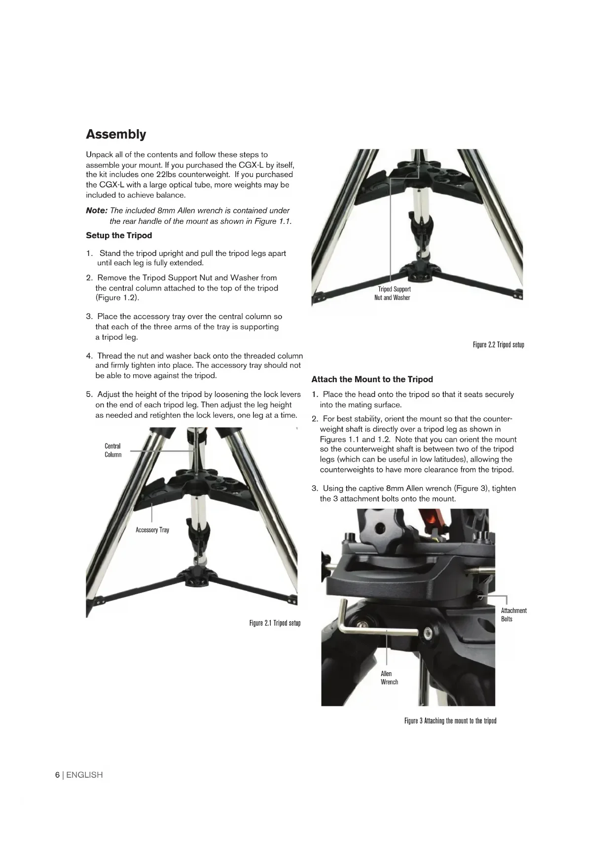
1. Place the head onto the tripod so that it seats securely
into the mating surface.
2. For best stability, orient the mount so that the counter-
weight shaft is directly over a tripod leg as shown in Figures 1.1 and 1.2. Note that you can orient the mount so the counterweight shaft is between two of the tripod legs (which can be useful in low latitudes), allowing the counterweights to have more clearance from the tripod.
3. Using the captive 8mm Allen wrench (Figure 3), tighten
the 3 attachment bolts onto the mount. Figure 2.1 Tripod setup Figure 2.2 Tripod setup Figure 3 Attaching the mount to the tripod Accessory Tray Central Column Allen Wrench Tripod Support Nut and Washer Attachment BoltsENGLISH | 7 Roughly Polar Align the Mount Before more weight is added to the mount and tripod, roughly position the mount so that it’s pointing north (or south if in the southern hemisphere), and set to your latitude. Loosen the two altitude lock knobs and turn the altitude adjustment knob (Figure 1.1) until you are roughly set to your latitude indicated on the latitude scale (Figure 1.2), then retighten the altitude lock knobs. The scale is intended for rough polar alignment only. A more precise polar alignment can be achieved later with the assistance of the computerized hand control. Add the Counterweight(s) Remove the stop nut at the end of the counterweight shaft, add the counterweight(s), then thread the stop nut back on. Keep the Counterweight shaft pointed downward. Attach the Telescope to the Mount
1. Make sure both R.A. and Dec clutch levers are tightened.
2. Loosen the dovetail saddle lock knobs enough to allow
the dovetail to fit into the saddle. Note the arrow should be pointing to the same side as the handle labeled “Celestron” (Figure 4).
3. Slide the telescope’s dovetail bar into the dovetail saddle
of the mount. Tighten the telescope in place with the two lock knobs (Figure 5). The CGX-L fits the large Celestron CGE-style dovetail and the smaller CG-5-style dovetail, also common to the Losmandy D(1) and Vixen-style(2) dovetail. 1: Test fit your Losmandy dovetail bar before securing your telescope to the mount. Sizes and dovetail angles across different manufacturers can vary.
2. Test fit your Vixen dovetail bar before securing your telescope to the mount. Be
aware that some of the Vixen-style dovetails are not flat and have different heights along the bar. Depending on the length of the flat, it can affect the fit onto the dovetail saddle of the mount. Balance the Mount Right Ascension Axis: Carefully unlock the clutch lever for R.A. and position the counterweight shaft so that it’s horizontal. Without letting go of the telescope, check to see which side the balance is in favor of. Slide the counterweights as needed so the R.A. axis does not move when the clutch is unlocked. Declination Axis: With the counterweight shaft still positioned horizontally, carefully unlock the clutch lever for Dec and check which way the optical tube is balanced. Slide the optical tube forward or backward as needed to achieve balance. For large and heavy telescopes, return the telescope to the home position before loosening the dovetail saddle lock knobs (Figure 6). Figure 4 Attaching the mount to the tripod Figure 5 Telescope dovetail securely in place Figure 6 Balancing the mount Dovetail Orientation Arrow Dovetail Lock Knobs8 | ENGLISH
4. Using the direction keys, center the star in the eyepiece of
your telescope and press ALIGN.
5. Select a second star from the list and repeat the process
from steps 2-4. When prompted to add a Calibration Star, you can either press BACK to complete the alignment, or for best results, proceed to add a calibration star. For best results, add at least one Calibration Star. This will improve the pointing accuracy of your mount.
6. When prompted to “Add Calibration Star”, choose a star
from the list and press ENTER. The mount will slew to the other side of the meridian to add a calibration star.
7. Center the star in the viewfinder and press ENTER, then
center the star in your eyepiece and press ALIGN.
8. When prompted to add another calibration star, you may
continue to add more, or press BACK to complete the alignment. Selecting Objects Select from the object database categorized by Solar System, Stars, or Deep Sky. Within these menus (on keypad numbers 1, 2, and 3), you can select by object name or popular catalog number (such as M42 for Messier 42). Keypad 6 and 9 (up and down) allows you to scroll through any list in the hand control. Press ENTER to go to the selected object the list. Example of selecting and slewing to Messier M42 deep sky object:
- Press “0-4-2” on the keypad and press ENTER The SkyTour (keypad 5) is a great way to explore the sky without consulting a star chart. The Tour function will generate a list of the most interesting objects to observe for your time and location. Figure 8 Polar alignment adjustment Attach the Hand Control Holster Wrap the hook & loop strap and holster around the tripod leg and place the hand control in the holster. Plug in the Hand Control Plug the supplied NexStar+ hand control into one of the Aux ports.
Warning: Do not plug the hand control into the
Autoguide Port. Damage to the mount or hand control could occur. Similarly, do not plug an autoguider cable into the Aux port or damage could occur. Home Position The mount is in the “home” position when the counterweight shaft is pointing downward, and the telescope is pointing along the polar axis of the mount as pictured in (Figure 7). The mount’s internal switches will take the mount to its home position when you power it on (more on that in “Basic Usage”), but you can still manually position it before powering on the mount. Simply unlock the two lock levers, and move the telescope to the desired position. Polar Align the Mount The computerized go-to is capable of locating objects even if the mount is not perfectly polar aligned. However, polar alignment is necessary to achieve the best tracking accuracy of your mount, and it’s essential to astrophotography. When polar aligned, an Equatorial mount tracks the sky in one motion, keeping the object centered in the eyepiece or camera. CGX-L’s polar alignment system consists of an altitude adjuster and azimuth adjuster (Figure 8). An optional polar alignment scope is available from Celestron and attaches to the mount. The optional polar axis scope does not pass through the R.A. axis because that area is used for internal cabling. If you are not using the optional polar alignment scope, you can achieve a rough polar alignment by sighting through the viewfinder of your telescope, and adjusting the mount until you center Polaris in the eyepiece of your telescope. This will get you to within about three- quarters of a degree within the North Celestial Pole (NCP). Basic Usage With your mount assembled and polar aligned, proceed to startup the mount: Powering the Mount The CGX-L mount can be powered by the supplied car battery adapter to a 12VDC battery source that can deliver at least 3 amperes of current. Or you may use an optional AC adapter that delivers at least 3 amperes of current. AC power adapters with threaded barrel connectors are available from Celestron. Figure 7 Telescope in the home position Altitude Adjustment Knobs Altitude Lock Knobs Azimuth Adjustment KnobsENGLISH | 9 Home Position and Site Information
1. Plug the included NexStar+ Hand Control into one of the
Aux ports. You can plug into any of Aux 1 to 4 ports.
2. Plug the power cable into the power input port on the
mount. Be sure to secure the power cable with the threaded barrel connector.
3. Turn the power switch on.
4. When the hand control displays “CGX-L Ready”, press
ENTER twice. The mount will proceed to move to the home switch position.
5. Select City Database or Custom Site.
- In City Database, select the nearest city to your location. - If you choose Custom Site, you will have to enter the longitude, latitude and time zone of your location.
6. Once the location is selected, proceed to enter the date
and time. The CGX-L has a Real-Time Clock (RTC) which stores the date, time and location information for the next time you use the mount. Alignment Prerequisite: The mount must be roughly polar aligned, with the date, time and location information correctly entered as outlined before this step.
1. For best alignment results, choose Two Star Align and
press ENTER. You can also choose from Solar System, One Star, Last Align, or Quick Align. The Scroll buttons 6 and 9 on the keypad are used to scroll through any list selection in the hand control.
2. Select the first star from the named star list. Use the
Scroll buttons 6 (up) and 9 (down) on the keypad to scroll through the star names. They consist of the brightest and easiest stars to find. Press ENTER when you have selected a suitable star. If your mount is at least roughly polar aligned, the mount will slew to the approximate location of the star. The default selection of stars is on the west side of the meridian. If your sky is obstructed in the west or you wish to choose from stars on the east side of the meridian, press the MENU button on the keypad.
3. Using the direction keys, slew the telescope to the
selected named star and center it in the viewfinder of your telescope, then press ENTER. The mount will automatically adjust the motor speed for fine centering.
4. Using the direction keys, center the star in the eyepiece of
your telescope and press ALIGN.
5. Select a second star from the list and repeat the process
from steps 2-4. When prompted to add a Calibration Star, you can either press BACK to complete the alignment, or for best results, proceed to add a calibration star. For best results, add at least one Calibration Star. This will improve the pointing accuracy of your mount.
6. When prompted to “Add Calibration Star”, choose a star
from the list and press ENTER. The mount will slew to the other side of the meridian to add a calibration star.
7. Center the star in the viewfinder and press ENTER, then
center the star in your eyepiece and press ALIGN.
8. When prompted to add another calibration star, you may
continue to add more, or press BACK to complete the alignment. Selecting Objects Select from the object database categorized by Solar System, Stars, or Deep Sky. Within these menus (on keypad numbers 1, 2, and 3), you can select by object name or popular catalog number (such as M42 for Messier 42). Keypad 6 and 9 (up and down) allows you to scroll through any list in the hand control. Press ENTER to go to the selected object the list. Example of selecting and slewing to Messier M42 deep sky object:
- Press “0-4-2” on the keypad and press ENTER The SkyTour (keypad 5) is a great way to explore the sky without consulting a star chart. The Tour function will generate a list of the most interesting objects to observe for your time and location. Figure 8 Polar alignment adjustment10 | ENGLISH Precise Polar Alignment Celestron’s All-Star Polar Alignment allows you to precisely polar align your mount without using Polaris or a polar axis finder. This software-assisted polar alignment allows you to choose a convenient star. Prerequisite: The CGX-L must first be aligned with a Two Star, One Star, or Solar System Align.
1. Select a suitable bright star from the NexStar hand
control’s database. Slew the telescope to the star.
2. Press the ALIGN button. Select “Polar Align” then
“Align Mount” from the list.
3. The telescope will then re-slew to the alignment star
and ask you to center it in the eyepiece in order to “sync” on the star. Press ENTER, center the star with the arrow keys, then press ALIGN to sync on the star.
4. Press ENTER and the telescope will slew to the
position that the star should be if it were accurately polar-aligned. At this point, do not use the hand control to center the star.
5. Use the mount’s altitude and azimuth adjustments
to center the star in the eyepiece.
6. Press the ALIGN button.
The mount is now precisely polar aligned. You may proceed to use the mount without a new go to alignment. Motion Range in Mount Sofware Range The CGX-L employs software controlled limit sensors which detect when the mount has nearly reached its mechanical range limit. Once the mount reaches the sensor, the motor will decelerate to a stop and a “Limit Switch” warning message will appear. The mount will no longer slew in the direction of the limit switch until you reverse directions. Mechanical Range The CGX-L uses internal cabling so the mount is designed not to move more than a certain range. Both axes are limited by a hard stop built into the mount. This limited range can also help prevent unintentional interference between your telescope and the mount or tripod. If for any reason the mount exceeds the software limit switch (or if the clutch is unlocked and the mount is manually moved), the mount will halt at the hard stop. R.A. limit (Figure 9.1) allows you to track 20º past the meridian. If you leave the mount unattended while it’s tracking, it will automatically stop before reaching the mechanical hard stop. Dec limit (Figure 9.2) contains enough slew range to reach any portion of the sky. Figure 9.1 One side of R.A. mechanical limit Figure 9.2 One side of DEC mechanical limitENGLISH | 11 Adjusting the Mount for Very High or Low Latitudes The EQ head can be set on the tripod in three different positions to optimize the center of balance over the tripod, or to provide more clearance when needed at lower latitudes. Additionally, the EQ head can be positioned so that the counterweight shaft is directly above a tripod leg (recommended default), or rotated so that the counterweight shaft is between two of the tripod legs for additional low latitude clearance.
1. Remove the head from the baseplate by removing the 4 socket-
2. Carefully remove the 8 socket head screws located under the head.
Once they are removed, the altitude adjustment mechanism will be the only thing securing the bottom plate of the EQ head (Figure 10.1).
3. Turn the altitude adjuster knob until the threaded holes on the bottom
of the mount align with the new set of holes on the bottom plate. Shift the plate forward (towards the counterweight shaft side) if you wish to use at lower latitudes. Shift the plate backward (towards the altitude adjustment knob) if you wish to use at higher latitudes (Figure 10.2). USB Port on the Mount The USB port on the CGX-L is used to interface with your PC for use with the dedicated telescope control software. Simply connect a standard USB B type cable into the USB port on the mount, and plug into your PC. The mount should automatically install and assign a COM port to your devices. The USB port on the mount is not intended to be used with ASCOM or third party telescope control software. To control the mount via ASCOM, connect your PC to the NexStar+ hand control’s mini USB port. Mini USB Port on the NexStar+ Hand Control The mini USB port on the hand control can be used to connect to your PC for these purposes:
1. To update the hand control and motor control board firmware.
2. To interface with third-party software that uses ASCOM.
Aux Ports Aux 1 and Aux 2 can be used for the NexStar+ hand control, as well as optional accessories such as the StarSense AutoAlign and SkyPortal WiFi module. The CGX-L is equipped with two additional Aux ports located under the dovetail saddle. You can use any of the same accessories in these Aux ports. They move with the declination axis of the mount, and depending on your cable configuration, it can be a convenient location to plug in your accessories. Autoguide Ports The autoguide port should only be used for autoguide camera relays. CAUTION: Never plug the NexStar+ hand control or other accessory into the autoguide port. Damage could result. The CGX-L is equipped with a redundant autoguider port, located next to Aux 3 and Aux 4 near the dovetail saddle. You can only use one autoguide port. The redundant port is intended to provide you with the best option that suits your particular cable configuration. Figure 10.2 Changing the mount position on the tripod head DEFAULT POSITION BACK POSITION FRONT POSITION Figure 10.1 Socket Head Screws Securing Baseplate Baseplate12 | ENGLISH NexStar+ Hand Control
1. Liquid Crystal Display (LCD) Window: Red
backlighting for comfortable nighttime viewing of telescope information and scrolling text. Remove the clear protective tape from the screen before use.
2. Align: Instructs the telescope to begin the default alignment
procedure. It is also used to select star or object as an alignment position.
3. Direction Keys: Allow complete control of your telescope
in any direction. Use the direction keys to center objects in the eyepiece or to manually slew your telescope.
4. Catalog Keys: Allow direct access to each of the main
catalogs in the database of thousands of objects. Your telescope contains the following catalogs in its database:
- Solar System- All 7 planets in our Solar System plus the Moon, Sun and Pluto.
- Stars- Custom lists of all the brightest stars, double stars, variable stars, constellations and asterisms.
- Deep Sky- Custom lists of all the best Galaxies, Nebulae and Clusters, as well as the complete Messier and select NGC objects.
5. Identify: Searches your telescope’s database and
displays the name and offset distances to the nearest matching objects.
6. Menu: Displays setup and utilities functions, such as
tracking rate, user defined objects and others.
7. Option (Celestron Logo): Works similar to the SHIFT
key on a keyboard and can be used in combination with other keys to access more advanced features and functions to be added with later firmware updates.
8. Enter: Pressing ENTER allows you to select any of your
telescope’s functions, accept entered parameters and slews the telescope to displayed objects.
9. Back: Pressing BACK will take you out of the current
menu and display the previous level of the menu path. Press BACK repeatedly to get back to a main menu or use to erase data entered by mistake.
10. Sky Tour: Activates the tour mode, which seeks out all
of the best objects in the sky and automatically slews your telescope to those objects.
11. Scroll Keys: Used to scroll UP and DOWN within any of
the menu lists. A double arrow symbol on the right side of the LCD indicates that the scroll keys can be used to view additional information. The buttons have an angled shape to make it easier to locate without looking.
12. Motor Speed: Similar to the Rate Button on the original
NexStar hand control, it allows you to change the motor’s speed when the direction keys are pressed.
13. Object Info: Displays coordinates and valuable
information about objects selected from your telescope’s database.
14. Mini Usb Port (cable not included): Links to PC
to control telescope with desktop or to perform firmware updates.
15. Help Menu: In future firmware updates, this button will
offer troubleshooting tips. For your convenience, it currently functions as a shortcut to the Messier Catalog. Figure 11
Figure 11.2ENGLISH | 13 Selecting an Object Once the telescope is properly aligned, you can choose an object from any of the catalogs in the NexStar+ hand control’s database. The hand control has a key designated for each category of objects in its database; Solar System objects, Stars and Deep Sky objects.
- Solar System – The Solar System catalog will display all of the planets (and Moon) in our solar system that are currently visible in the sky. To allow the Sun to be displayed as an option in the database, see Allow Sun option in the Database Setup section of the manual.
- Stars – The Stars catalog displays custom lists of all the brightest stars, double (binary) stars, variable stars, constellations and selected asterisms.
- Deep Sky – The Deep Sky catalog displays a list of all of the best galaxies, nebulae and clusters, as well as the complete Messier and select NGC objects. There is also an alphabetical list of all deep sky objects in order by their common name. Use the SCROLL keys to scroll through the catalogs to find the object you wish to view. When scrolling through a long list of objects, holding down either the UP or DOWN key will allow you to scroll through the catalog at a rapid speed. Slewing to an Object Once the desired object idisplayed on the hand control screen, you have two options:
- Press the OBJECT INFO Key. This will give you useful information about the selected object such as magnitude, constellation and extended information about the most popular objects. - Use the UP/DOWN arrow buttons to scroll through the displayed object info. - Use the BACK button to return to the object database.
- Press the ENTER Key. This will automatically slew the telescope to the coordinates of the object displayed on the hand control. While the telescope is slewing to the object, the user can still access many of the hand control functions (such as displaying information about the object). NOTE: The Messier, NGC and SAO catalogs require the user to enter a numeric designation. Once you have selected the appropriate catalog button and selected the Messier, NGC or SAO catalog, you will see a flashing cursor indicating you are in numeric entry mode. Enter the catalog number for the object you want to view. Press ENTER to command the telescope to slew to the object, or hold the OPTION button (the Celestron logo) and press OBJECT INFO to see information about the object you selected. CAUTION: Never slew the telescope when someone is looking into the eyepiece. The telescope can move at fast slew speeds and may hit an observer in the eye. Motor Speed Button The MOTOR SPEED button, similar to the Rate button on the original NexStar hand control, allows you to instantly change the speed rate of the motors from high speed slew rate to precise guiding rate or anywhere in between. Each rate corresponds to a number on the hand control key pad. The number 9 button is the fastest rate (approximately 3.5° per second, depending on the mount) and is used for slewing between objects and locating alignment stars. The number 1 button on the hand control is the slowest rate (half sidereal) and can be used for accurate centering of objects in the eyepiece. To change the speed of the motors:
- Press the MOTOR SPEED key on the hand control. The LCD will display the current motor speed.
- Press the number on the hand control that corresponds to the desired speed. The hand control has a “double button” feature that allows you to instantly speed up the motors without having to choose a speed. To use this feature, simply press the arrow button that corresponds to the direction that you want to move the telescope. While holding that button down, press the opposite direction button. This will increase the speed to the maximum slew rate. When using the hand control’s up and down direction buttons, the slower slew rates (6 and lower) move the motors in the opposite direction than the faster slew rates (7- 9). This is done so that an object will move in the appropriate direction when looking into the eyepiece (i.e. pressing the UP arrow button will move the star upwards in the field of view of the eyepiece). However, if any of the slower slew rates (rate 6 and below) are used to center an object in the StarPointer, you may need to press the opposite directional button to make the telescope move in the correct direction.14 | ENGLISH The Hand Control Menu The “Hand Control” menu allows you to customize certain features of the NexStar+ hand control. To access this menu, press the MENU button (#7 on the keypad) and use the scroll buttons to select “Hand Control” and press ENTER. Use the scroll buttons to select from the following options:
- Lights Control: Independently adjust the brightness of the number keypad and the LCD.
- Scrolling Menu: Adjust how fast words move across the face of the LCD.
- Toggle Bold Font: Change the format of the font displayed on the LCD from normal to boldface.
- Set Contrast: Use the scroll keys to adjust the contrast of the LCD.
- Set Language: Change the displayed language on the LCD. NOTE: The Set Language feature may also appear the first time you use your new hand control. You may also initiate it at any time by holding down the Option button (the Celestron logo) for 10 seconds while powering up the telescope. Alignment Procedures In order for the telescope to accurately point to objects in the sky, it must first be aligned with known positions (stars) in the sky. With this information, the telescope can create a model of the sky, which it uses to locate any object with known coordinates. There are many ways to align your telescope with the sky depending on what information the user is able to provide:
- Two Star Align uses the entered time/location information and allows the user to select which two alignment stars the telescope will automatically slew to.
- One Star Align uses the same time/location information but only uses one star for alignment.
- Solar System Align will display a list of visible daytime objects (planets and the Moon) available to align the telescope.
- Quick-Align will ask you to input all the same information as you would for the Two Star Align procedure. However, instead of slewing to the alignment stars for centering and alignment, the telescope bypasses this step and simply models the sky based on the information given.
- Last Alignment restores your last saved star alignment and switch position. Last Alignment also serves as a good safeguard in case the telescope should lose power. Two Star Align Two-Star Align allows the user to select two stars on which to align the telescope. To align your telescope using the Two-Star Align method:
1. Select Two-Star Align from the alignment choices given.
Based on the date and time information entered, the hand control will automatically select and display a bright star that is above the horizon.
- Press ENTER to select this star as your first alignment star.
- If for some reason the chosen star is not visible (perhaps behind a tree or building), press BACK to have the hand control automatically select the next brightest star.
- Or you can use the Up/Down keys to browse the entire Named Star list and select any one of over two hundred alignment stars.
2. Once the telescope is finished slewing to your first
alignment star, the display will ask you to use the arrow buttons to align the selected star with the cross hairs in the center of the finderscope. When centered in the finder, press ENTER. The display will then instruct you to center the star in the field of view of the eyepiece. When the star is entered, press ALIGN to accept this star as your first alignment star.
3. After the first alignment star has been entered, the hand
control will automatically select a second alignment star and have you repeat this procedure for that star. When the telescope has been aligned on both stars, the display will ask you if you wish to add additional calibration stars. Calibration stars are used to improve the pointing accuracy of your telescope by compensating for subtle opto-mechanical misalignments between the telescope optics and the mount. Therefore, it is usually a good idea to add at least one additional calibration star to improve the mount’s all-sky pointing accuracy.
4. Press ENTER to select a calibration star. Select a star the
same way you did with the first two alignment stars and press ENTER. You will notice that all the calibration stars displayed are located on the opposite side of the side of the sky (Meridian) as the original alignment stars. This is essential for an accurate calibration of the mount. Finally, you can choose to continue to add additional calibration stars or Press BACK to complete the alignment. Note: East/West Filtering – In order to ensure the best possible full-sky pointing accuracy, your computerized mount automatically filters and chooses its initial alignment stars so that the first two alignment stars are located on one side of the Meridian and any calibration stars are on the opposite side of the Meridian, as indicated by the “W” or “E” displayed in the upper-right corner of the LCD. East/West filtering can be changed simply by pressing the MENU button at any time during the alignment process.ENGLISH | 15 Tips for Adding Calibration Stars:
- Although for casual observing it is not necessary to add calibration stars, it is recommended that you add as many as three calibration stars for optimal point accuracy.
- Choosing calibration stars that are near the celestial equator offer the better results than stars near the celestial poles.
- Although it is not necessary to use calibration stars if the telescope mount has not been moved since its original alignment/calibration, it may be necessary to recalibrate the telescope if the optical tube has been removed for any reason. Note: Meridian – The Meridian is an imaginary line in the sky that starts at the North celestial pole and ends at the South celestial pole and passes through the zenith. If you are facing south, the meridian starts from your Southern horizon and passes directly overhead to the North celestial pole. Quick-Align Quick-Align uses all the date and time information entered at startup to align the telescope. However, instead of slewing to the alignment stars for centering and alignment, the telescope bypasses this step and simply models the sky based on the information given. This will allow you to roughly slew to the coordinates of bright objects like the Moon and planets and provides the telescope with information needed to track objects in any part of the sky (depending on accuracy of polar alignment). Quick-Align is not meant to be used to accurately locate small or faint deep-sky objects or to track objects accurately for astroimaging. To use Quick-Align, simply select Quick Align from the alignment options and press ENTER. The telescope will automatically use the entered date/time parameters to align itself with the sky and display Alignment Successful. Note: Once a Quick-Align has been done, you can use the Re-alignment feature (see below) to improve your telescope’s pointing accuracy. Last Alignment The Last Alignment method will automatically recall the last stored index positions to continue using the alignment that was saved when the telescope was last powered down. This is a useful feature should your telescope accidentally lose power or be powered down. Re-Alignment The mount has a re-alignment feature which allows you to replace any of the original alignment stars with a new star or celestial object. This can be useful in several situations:
- If you are observing over a period of a few hours, you may notice that your original two alignment stars have drifted towards the west considerably. (Remember that stars are moving at a rate of 15° every hour). Aligning on a new star that is in the eastern part of the sky will improve your pointing accuracy, especially on objects in that part of the sky.
- If you have aligned your telescope using the Quick-Align method, you can use Re-Align to align on actual objects in the sky. This will improve the pointing accuracy of your telescope without having to re-enter additional information.
- If you have used the computer-assisted polar alignment method and have manually moved the mount, it may be necessary to re-align the mount for improved pointing accuracy. To replace an existing alignment star with a new alignment star:
1. Select the desired star (or object) from the database and
2. Carefully center the object in the eyepiece.
3. Once centered, press the BACK button until you are at
the hand control to select Alignment Stars from the list of options.
5. The display will then ask you which alignment star you
want to replace. Use the UP and Down scroll keys to select the alignment star to be replaced. It is usually best to replace the star closest to the new object. This will space out your alignment stars across the sky.
6. Press ALIGN to make the change.16 | ENGLISH
Object Catalog Selecting an Object Once the telescope is properly aligned, you can choose an object from any of the catalogs in the NexStar+ hand control’s database. The hand control has a key designated for each category of objects in its database; Solar System objects, Stars and Deep Sky objects.
- Solar System – The Solar System catalog will display all the planets (and Moon) in our Solar System that are currently visible in the sky. To allow the Sun to be displayed as a selectable object in the database, see the Sun Menu option in Scope Setup Menu.
- Stars – The Stars catalog displays custom lists of all the brightest stars, double (binary) stars, variable stars, constellations and selected asterisms.
- Deep Sky – The Deep Sky catalog displays a list of all the best galaxies, nebulae and clusters, as well as the complete Messier and select NGC objects. There is also an alphabetical list of all deep sky objects in order by their common name. Use the scroll keys to scroll through the catalogs to find the object you want to view. When scrolling through a long list of objects, holding down either the UP or DOWN key will allow you to scroll through the catalog rapidly. Slewing to an Object Once the desired object is displayed on the hand control screen, you have two options:
- Press the OBJECT INFO Key. This will give you useful information about the selected object such as magnitude, constellation and extended information about the most popular objects.
- Press the ENTER Key. This will automatically slew the telescope to the coordinates of the object displayed on the hand control. While the telescope is slewing to the object, the user can still access many of the hand control functions (such as displaying information about the object). NOTE: The Messier, NGC and SAO catalogs require the user to enter a numeric designation. Once you have selected the appropriate catalog button and selected the Messier, NGC or SAO catalog, you will see a flashing cursor indicating you are in numeric entry mode. Enter the catalog number for the object you want to view. Press ENTER to command the telescope to slew to the object or hold the OPTION button (the Celestron logo) and press OBJECT INFO to see information about the object you selected. CAUTION: Never slew the telescope when someone is looking into the eyepiece. The telescope can move at fast slew speeds and may hit an observer in the eye. SkyTour Button The CGX-L mount includes a tour feature which allows you to choose from a list of interesting objects based on the date and time in which you are observing. The automatic tour will display only those objects that are within your set catalog filters limits. To activate the Tour feature, press the SKY TOUR key on the hand control.
1. Press the SKY TOUR button on the hand control.
2. Use the SCROLL buttons to select Best of Tonight.
3. The CGX-L mount will automatically slew in azimuth to its
starting position which will help minimize the chance of wrapping the power cord during the tour.
4. The hand control will display the best objects to observe
that are currently in the sky.
- To see information and data about the displayed object, press the OBJECT INFO key. Press it once to display the coordinates of the object. Press it again to display the coordinates of the object. Press it again to display the text description. Press BACK to return to the previous screen.
- To slew to the object displayed, press ENTER.
- To see the next tour object, press the DOWN key. Identify Button Pressing the IDENTIFY button will search the mount’s da- tabase catalogs and display the name and angular distances to the nearest matching objects from the telescope’s current location. This feature can serve two purposes. First, it can be used to identify an unknown object in the field of view of your eyepiece. Additionally, Identify Mode can be used to find other celestial objects that are close to the objects you are currently observing. For example, if your telescope is pointed at the brightest star in the constellation Lyra, choosing Identify will no doubt return the star Vega as the star you are observing. However, the Identify feature will also search its NGC and Solar System databases and display any planets or Deep Sky objects that are close by. In this example, the Ring Nebula (M57) would display as being approximately 6° away. The brightness and proximity of the objects displayed can be defined by the user using the Identify Filter under Telescope Setup.ENGLISH | 17 Direction Buttons The hand control has four direction buttons in the center of the hand control which control the telescope motion in altitude (up and down) and azimuth (left and right). The telescope can be controlled at nine different speed rates. 1 = 1/2x 6 = .3° / sec 64x 2 = 1x 7 = 1° / sec 3 = 4x 8 = 2° / sec 4 = 8x 9 = 3° / sec 5 = 16x Motor Speed Button Pressing the MOTOR SPEED button (12) allows you to instantly change the speed rate of the motors from high speed slew rate to precise guiding rate or anywhere in between. Each rate corresponds to a number on the hand controller key pad. The number 9 is the fastest rate and is used for slewing between objects and locating alignment stars. The number 1 on the hand control is the slowest rate (2x sidereal) and can be used for accurate centering of objects in the eyepiece. To change the speed rate of the motors:
- Press the MOTOR SPEED key on the hand control. The LCD will display the current speed rate.
- Press the number on the hand control that corresponds to the desired speed. The hand control has a “double button” feature that allows you to instantly speed up the motors without having to choose a speed rate. To use this feature, simply press the arrow button that corresponds to the direction that you want to move the telescope. While holding that button down, press the opposite directional button. This will increase the speed to the maximum slew rate. When using the UP and DOWN buttons on the hand control, the slower slew rates (6 and lower) move the motors in the opposite direction than the faster slew rates (7- 9). This is done so that an object will move in the appropriate direction when looking into the eyepiece (i.e., pressing the up arrow button will move the star upwards in the field of view of the eyepiece). However, if any of the slower slew rates (rate 6 and below) are used to center an object in the starpointer, you may need to press the opposite directional button to make the telescope move in the correct direction. Help Button In future firmware updates, this button will offer troubleshooting tips. For your convenience, it currently functions as a shortcut to the Messier Catalog. Menu Button The CGX mount contains many user-defined setup functions designed to give the user control over the telescopes many features. All of the setup and utility features can be accessed by pressing the MENU key and scrolling through the options below. Tracking Menu Tracking Mode – This allows you to change the way the telescope tracks depending on the type of mount being used to support the telescope. The telescope has three different tracking modes:
- EQ North – Used to track the sky when the telescope is polar aligned in the Northern Hemisphere.
- EQ South – Used to track the sky when the telescope is polar aligned in the Southern Hemisphere.
- Off – When using the telescope for terrestrial (land) observation, the tracking can be turned off so that the telescope never moves. Tracking Rate – In addition to being able to move the telescope with the hand control buttons, your telescope will continually track a celestial object as it moves across the night sky. The tracking rate can be changed depending on what type of object is being observed:
- Sidereal – This rate compensates for the rotation of the Earth by moving the telescope at the same rate as the rotation of the Earth, but in the opposite direction. When the telescope is polar aligned, this can be accomplished by moving the telescope in right ascension only.
- Lunar – Used for tracking the Moon when observing the lunar landscape.
- Solar – Used for tracking the Sun when solar observing with the proper filter. View Time-Site Menu This menu displays the current time and longitude/latitude downloaded from the optional SkySync GPS receiver. It will also display other relevant time-site information like time zone, daylight saving and local sidereal time. Local sidereal time (LST) is useful for knowing the right ascension of celestial objects that are located on the Meridian at that time. View Time-Site will always display the last saved time and location entered while it is linking with the GPS. Once current information has been received, it will update the displayed information. If GPS is switched off or not present, the hand control will only display the last saved time and location. The Hand Control Menu The “Hand Control” menu allows you to customize certain features of the NexStar+ hand control. To access this menu, press the MENU button (#7 on the keypad) and use the scroll buttons to select “Hand Control” and press ENTER.18 | ENGLISH Use the scroll buttons to select from the following options:
- Lights Control: Independently adjust the brightness of the number keypad and the LCD.
- Scrolling Menu: Adjust how fast words move across the face of the LCD.
- Toggle Bold Font: Change the format of the font displayed on the LCD from normal to boldface.
- Set Contrast: Use the scroll keys to adjust the contrast of the LCD.
- Set Language: Change the displayed language on the LCD. NOTE: The Set Language feature may also appear the first time you use your new hand control. You may also initi- ate it at any time by holding down the Option button (the Celestron logo) for 10 seconds while powering up the telescope. Scope Setup Menu Setup Time-Site – Allows the user to customize the telescope’s display by changing time and location parameters (such as time zone and daylight savings). Anti-backlash – All mechanical gears have a certain amount of backlash or play between the gears. This play is evident by how long it takes for a star to move in the eyepiece when the hand control arrow buttons are pressed (especially when changing directions). The CGX-L anti-backlash feature allows the user to compensate for backlash by inputting a value which quickly rewinds the motors just enough to eliminate the play between gears. The amount of compensation needed depends on the slewing rate selected; the slower the slewing rate the longer it will take for the star to appear to move in the eyepiece. There are two values for each axis, positive and negative:
- Positive is the amount of compensation applied when you press the button in order to get the gears moving quickly without a long pause.
- Negative is the amount of compensation applied when you release the button, winding the motors back in the other direction to resume tracking. Normally, both values should be the same. You will need to experiment with different values (from 0-99); a value between 20 and 50 is usually best for most visual observing, whereas a higher value may be necessary for photographic guiding. To set the anti-backlash value, scroll down to the anti-backlash option and press ENTER. While viewing an object in the eyepiece, observe the responsiveness of each of the four arrow buttons. Note which directions you see a pause in the star movement after the button has been pressed. Working one axis at a time, adjust the backlash settings high enough to cause immediate movement without resulting in a pronounced jump when pressing or releasing the button. Now, enter the same values for both positive and negative directions. If you notice a jump when releasing the button but setting the values lower results in a pause when pressing the button, use the higher value for positive, but use the lower value for negative. The telescope will remember these values and use them each time it is turned on until they are changed. Filter Limits – When an alignment is complete, the telescope automatically knows which celestial objects are above the horizon. As a result, when scrolling through the database lists (or selecting the Tour function), the hand control will display only those objects that are known to be above the horizon when you are observing. You can customize the object database by selecting altitude limits that are appropriate for your location and situation. For example, if you are observing from a mountainous location where the horizon is partially obscured, you can set your minimum altitude limit to read +20°. This will make sure that the hand control only displays objects that are higher in altitude than 20°. TIP: If you want to explore the entire object database, set the maximum altitude limit to 90° and the minimum limit to –90°. This will display every object in the database lists regardless of whether it is visible in the sky from your location. Direction Buttons – The direction a star appears to move in the eyepiece changes depending on which side of the Meridian the telescope tube is on. This can create confusion especially when guiding on a star when doing astroimaging. To compensate for this, the direction of the drive control keys can be changed. To reverse the button logic of the hand control, press the MENU button and select Direction Buttons from the Utilities menu. Use the Up/Down arrow keys (10) to select either the azimuth (right ascension) or altitude (declination) button direction and press ENTER. Select either positive or negative for both axes and press ENTER to save. Setting the azimuth button direction to positive will move the telescope in the same direction that the telescope tracks (i.e., towards the west). Setting the altitude buttons to positive will move the telescope counterclockwise along the declination axis. GoTo Approach – Lets the user define the direction that the telescope will approach when slewing to an object. This allows the user the ability to minimize the effects of backlash when slewing from object to object. Just like with Direction Buttons, setting GoTo Approach to positive will make the telescope approach an object from the same direction as tracking (west) for azimuth and counterclockwise in declination. Declination GoTo approach will only apply while the telescope tube is on one side of the Meridian. Once the tube passes over to the other side of the Meridian, the GoTo approach will need to be reversed. To change the GoTo approach direction, simply choose GoTo Approach from the Scope Setup menu, select either Altitude or Azimuth approach, choose positive or negative and press ENTER.ENGLISH | 19 HINT: In order to minimize the affect of gear backlash on pointing accuracy, the settings for Button Direction should ideally match the settings for GoTo Approach. By default, using the up and right direction buttons to center alignment stars will automatically eliminate much of the backlash in the gears. If you change the GoTo approach of your telescope, it is not necessary to change the Button Direction as well. Simply take notice of the direction the telescope moves when completing its final GoTo approach. If the telescope approaches its alignment star from the west (negative azimuth) and clockwise (negative altitude) then make sure that the buttons used to center the alignment stars also move the telescope in the same directions. Autoguide Rate – Allows the user to set an autoguide rate as a percentage of sidereal rate. This is helpful when calibrating your telescope to a CCD autoguider for long exposure astroimaging. Meridian – This feature instructs the mount on how to respond when it is slewing to objects that are accessible from both sides of the Meridian. The Meridian feature allows the telescope tube to remain on a desired side of the mount when slewing, and continue to track according to the R.A. slew limits the user has set. See R.A. Limits below. The Meridian feature allows for four choices:
- Favor Current – Allows the mount to favor whatever side of the mount that it is currently on when slewing to objects close to the Meridian. For example, if your R.A. slew limits are set to allow the mount to track 10° past the meridian, then the telescope will continue to stay on its current side of the Meridian when slewing to objects that are as far as 10° beyond your Meridian.
- Favor West – If the target object is accessible from both sides of the mount, selecting “Favor West” instructs the mount to point to the object as if it were on the west side of the meridian. The optical tube will then be positioned on the east side of the mount and pointing west.
- Favor East – If the target object is accessible from both sides of the mount, selecting “Favor East” instructs the mount to point to the object as if it were on the east side of the meridian. The optical tube will then be positioned on the west side of the mount and pointing east.
- Disable – This is the default setting, which instructs the mount to always swing around to the other side of the pier as required to view objects on the opposite side of the Meridian. However, once at the desired object, the mount will continue to track past the Meridian according to the R.A. slew limits that have been set. Mount Settings – Once the mount settings have been calibrated (see Utilities section below) the values are stored and displayed in the hand control. It is not recommended that the calibration values be changed. However each setting can be changed if necessary to improve the performance of the telescope.
- Cone Value – This is the cone error value set when Utilities/Calibrate Mount/DEC Switch – Cone is carried out.
- DEC Index – This is the declination index error value that is stored when calibration stars are added after your initial star alignment.
- R.A. Index – This is the R.A. index error value set when Utilities/Calibrate Mount/R.A. Switch is carried out. R.A. Limits – Sets the limits that the telescope can slew or track in Right Ascension (R.A.) before stopping. The slew limits are represented in degrees and by default set to 0°, being the position of the telescope when the counterweight bar is extended out horizontally. However, the slew limits can be customized depending on your needs. For example, if you are using CCD imaging equipment that has cables that are not long enough to move with the telescope as it slews across the sky, you can adjust the slew limit on the side of the mount that is restricted by the cables, and command the mount the stop slewing before it reaches this point. Or if you are taking an image of an object that has just crossed the Meridian, you can set the limit to allow the mount to continue tracking in the same direction past the Meridian without the need to “flip” the telescope around to the opposite side of the mount (see Meridian feature above). Using the first example above, the user could slew the telescope in R.A. (azimuth) until it reaches the point that the cables are extended to their maximum. Then by displaying the telescope’s azimuth in this position (by looking at Get Axis Position under the Utilities menu) you can determine the telescope’s azimuth at its most extended position. Enter this azimuth reading for either the maximum or minimum azimuth slew limit to ensure that the telescope will not slew beyond this point. The telescope slew limits can be set to automatically stop anywhere between 40° above level to 20° below level. To set the R.A. slew limit select the following:
- R.A. East Limit – Enter a number between +40° to -20° to define the slew limit when the tube is on the east side of the mount.
- R.A. West Limit – Enter a number between +40° to -20° to define the slew limit when the tube is on the west side of the mount.
- Disable Limits – This disables any pre-defined values that have been entered and allows the mount to track the maximum amount pass the Meridian (i.e., -20° on both sides)20 | ENGLISH
WARNING: In order for the telescope to be able to slew
to a star from the direction that minimizes the amount of backlash in the gears, it may be necessary for the telescope to slew beyond the specified slew limit in order to approach the star from the correct direction. This can limit your ability to slew to an object by as much as 6° from the R.A. slew limit set in the hand control. If this proves to be a problem, the direction that the telescope takes to center an object can be changed. To change the telescopes slewing direction, see GoTo Approach under the Scope Setup menu. Custom Rate 9 – This allows you to customize the speed at which the mount slews to a target. You can set the R.A. and Dec axes individually. The max speed of the CGX-L is 4°/ second (3°/second is default). Utilities Menu Scrolling through the MENU (9) options will also provide access to several advanced utility functions within the telescope such as; Calibrate Mount, Hibernate as well as many others. Calibrate Mount – In order to optimize the performance and pointing accuracy of the telescope, the mount has built-in calibration routines allowing it to compensate for mechanical variation inherent in every German equatorial mount. Each calibration is completely automatic and in most cases only needs to be performed once. It is highly recommended that you take a few minutes to go through the mount calibration procedures.
- R.A. Switch – This procedure records the offset error when the right ascension index mark is aligned at start-up. Calibrating the R.A. Index will improve the accuracy of your initial star alignments when aligning the telescope in the future.
- GoTo Calibration – GoTo Calibration is a useful tool when attaching heavy visual or photographic accessories to the telescope. GoTo Calibration calculates the amount of distance and time it takes for the mount to complete its final slow GoTo when slewing to an object. Changing the balance of the telescope can prolong the time it takes to complete the final slew. GoTo Calibration takes into account any slight imbalances and changes the final GoTo distance to compensate. Home Position – The telescope’s “home” position is a user-definable position that is used to store the telescope when not in use. The home position is useful when storing the telescope in a permanent observatory facility. By default the Home position is the same as the index position used when aligning the mount. To set the Home position for your mount, simply use the arrow buttons on the hand control to move the telescope mount to the desired position. Select the Set option and press Enter. Select the GoTo option to slew the telescope back to the Home position at any time. Factory Settings – Returns the hand control to its original factory settings. Parameters such as backlash compensation values, initial date and time, longitude/latitude, along with slew and filter limits will be reset. However, stored parameters such as user defined objects will remain saved even when Factory Settings is selected. The hand control will ask you to press the “0” key before returning to the factory default setting. Version – Selecting this option will allow you to see the current version number of the hand control and motor control. The first set of numbers indicate the hand control software version. For the motor control, the hand control will display two sets of numbers; the first numbers are for azimuth and the second set are for altitude. Get Axis Position – Displays the relative altitude and azimuth for the current position of the telescope. GoTo Axis Position – Allows you to enter a specific relative altitude and azimuth position and slew to it. Hibernate – Hibernate allows the telescope to be completely powered down and still retain its alignment when turned back on. This not only saves power, but is ideal for those that have their telescope permanently mounted or leave their telescope in one location for long periods of time. To place your telescope in Hibernate mode:
1. Select Hibernate from the Utility Menu.
2. Move the telescope to a desire position and
3. Power off the telescope. Remember to never move
your telescope manually while in Hibernate mode. Once the telescope is powered on again, the display will read Wake Up. After pressing Enter, you have the option of scrolling through the time/site information to confirm the current setting. Press ENTER to wake up the telescope. HINT: Pressing BACK at the Wake Up screen allows you to explore many of the features of the hand control without waking the telescope up from hibernate mode. To wake up the telescope after BACK has been pressed, select Hibernate from the Utility menu and press ENTER. Do not use the direction buttons to move the telescope while in hibernate mode. Sun Menu For safety purposes, the Sun will not be displayed as a database object unless it is first enabled. To enable the Sun, go to the Sun Menu and press ENTER. The Sun will now be displayed in the Planets catalog and can be used as an alignment object when using the Solar System AlignmentENGLISH | 21 method. To remove the Sun from displaying on the hand control, once again select the Sun Menu from the Utilities Menu and press ENTER. Set Mount Position The Set Mount Position menu can be used to maintain your alignment in cases where you wish to disengage the clutches or similar situation. For instance, you might use this feature if you needed to rebalance the mount after having completed an alignment. To set the mount position, simply slew to a bright star in the named star list and select Set Mount Position. The hand control will sync on the star by asking you to center the star in the eyepiece and pressing the Align button. Once synced on the star, you are free to manually move the mount in both axes in order to rebalance. When you are ready to slew the telescope to your next object, just remember to manually return the tube to the same bright star and carefully center it in the eyepiece. Using this tool will invalidate the PEC index. Turn On/Off GPS – If using your telescope with the optional SkySync GPS accessory, you will need to turn the GPS on the first time you use the accessory. If you want to use the telescope’s database to find the coordinates of a celestial object for a future or past dates, you will need to turn the GPS off in order to manually enter a time other than the present. Turn On/Off RTC – Allows you to turn off the telescope’s internal real time clock. When aligning, the telescope still receives time information from the RTC. If you want to use the hand control database to find the coordinates of a celestial object for a future or past dates, you will need to turn the RTC off in order to manually enter a time other than the present. Periodic Error Correction (PEC) – PEC is designed to improve photographic quality by reducing the amplitude of the worm gear errors and improving the tracking accuracy of the drive. This feature is for advanced astrophotography and is used when your telescope is accurately polar aligned. User Objects Menu Your telescope can store up to 400 different user-defined objects in its memory. The objects can be daytime land objects or an interesting celestial object that you discover that is not included in the regular database. There are several ways to save an object to memory depending on what type of object it is: GoTo Object: To go to any of the user defined-objects stored in the database, scroll down to either “GoTo Sky Obj” or “GoTo Land Obj” and enter the number of the object you wish to select and press ENTER. The telescope will automatically retrieve and display the coordinates before slewing to the object. Save Sky Object: Your telescope stores celestial objects to its database by saving its right ascension and declination coordinates in the sky. This way the same object can be found each time the telescope is aligned. Once a desired object is centered in the eyepiece, simply scroll to the “Save Sky Obj” command and press ENTER. The display will ask you to enter a number between 1 and 200 to identify the object. Press ENTER again to save this object to the database. Save Database (Db)
- Object: This feature allows you to create your own custom tour of database objects by allowing you to record the current position of the telescope and save the name of the object by selecting it from any one of the database catalogs. These objects then can be accessed by selecting GoTo Sky Object.
- Enter R.A. - Dec: You can also store a specific set of coordinates for an object just by entering the R.A. and declination for that object. Scroll to the “Enter RA-DEC” command and press ENTER. The display will then ask you to enter first the R.A. and then the declination of the desired object.
- Save Land Object: The telescope can also be used as a spotting scope on terrestrial objects. Fixed land objects can be stored by saving their altitude and azimuth relative to the location of the telescope at the time of observing. Since these objects are relative to the location of the telescope, they are only valid for that exact location. To save land objects, once again center the desired object in the eyepiece. Scroll down to the “Save Land Obj” command and press ENTER. The display will ask you to enter a number between 1 and 200 to identify the object. Press ENTER again to save this object to the database. To replace the contents of any of the user defined-objects, simply save a new object using one of the existing identification numbers; the telescope will replace the previous user-defined object with the current one. Get R.A./DEC - Displays the right ascension and declination for the current position of the telescope. Goto R.A./Dec - Allows you to input a specific R.A. and declination and slew to it. Hint: To store a set of coordinates (R.A./Dec) permanently into the database, save it as a User-Defined Object as described above.22 | ENGLISH Identify Identify Mode will search any of the mount’s database catalogs or lists and display the name and offset distances to the nearest matching objects. This feature can serve two purposes. First, it can be used to identify an unknown object in the field of view of your eyepiece. Additionally, Identify Mode can be used to find other celestial objects that are close to the objects you are currently observing. For example, if your telescope is pointed at the brightest star in the constellation Lyra, choosing Identify and then searching the Named Star catalog will no doubt return the star Vega as the star you are observing. However, by selecting Identify and searching by the Named Object or Messier catalogs, the hand control will let you know that the Ring Nebula (M57) is approximately 6° from your current position. Searching the Double Star catalog will reveal that Epsilon Lyrae is only 1° away from Vega. To use the Identify feature:
- Press the Menu button and select the Identify option.
- Use the Up/Down scroll keys to select the catalog that you would like to search.
- Press ENTER to begin the search. NOTE: Some of the databases contain thousands of objects and can therefore take several minutes to return the closest objects. Precise GoTo The mount has a Precise Goto function that can assist in finding extremely faint objects and centering objects closer to the center of the field of view for astroimaging. Precise GoTo automatically searches out the closest bright star to the desired object and asks the user to carefully center the star in the eyepiece. The hand control then calculates the small difference between its GoTo position and its centered position. Using this offset, the mount will then slew to the desired object with enhanced accuracy. To use Precise GoTo:
- Choose Database to select the object that you want to observe from any of the database catalogs listed or;
- Choose R.A./DEC to enter a set of celestial coordinates that you wish to slew to.
2. Once the desired object is selected, the hand control
will search out and display the closest bright star to your desired object. Press ENTER to slew to the bright alignment star.
3. Use the direction buttons to carefully center the alignment
star in the eyepiece.
4. Press ENTER to slew to the desired object.ENGLISH | 23
CGX-L Main Menu Tree Menu Tracking Mode EQ North EQ South Off SiderealRate Solar Lunar View Time-Site Hand Control Saved Site Lights Control Keypad Level Display Level Scrolling Menu See Diagram - Next PageScope Setup Save Db Objects Set Contrast GoTo Sky ObjectsUser Objects GoTo Land Object Toggle Bold Font See Diagram - Next PageUtilities Enter RA & Dec Set Language Save Sky Objects Save Land Object Get RA-Dec GoTo RA Dec Identify Precise Goto24 | ENGLISH RA to Switch CGX-L Main Menu Tree Scope Setup Utilities Setup Time-Site Meridian Mount Settings Custom Rate 9 GoTo Approach RA Limits Anti-Backlash Filter Limits Direction Button Autoguide Rates Calibrate Mount PEC Record Version Sun Menu Home Position Get Axis Position Set Mount Position Goto Axis Position Turn on/off GPS Factory Setting Hibernate Turn on/off RTC Custom Site Dec Rate Dec Positive Disabled Dec Button Cone Value Dec Switch RA Switch RA Axis Enable City Database Dec Negative Favor Current RA Approach RA East Limit Set Rate RA Positive Favor West Dec Approach RA West Limit Dec Axis Enable RA Negative RA Button Favor East RA Rate Disable Limits Set Rate GoTo Set Dec to Switch Move to Switch PlaybackENGLISH | 25 Items needed:
1. PC with CFM installed
2. Mini USB cable (Not included)
3. Included NexStar+ Hand Control
4.12VDC 3A power for the mount Figure 12.2 Updating Hand Control Firmware Items needed:
1. PC with CFM installed
2. Mini USB cable (Not included)
3. Included NexStar+ Hand Control
- No additional power is required! User Supplied Mini USB Cable NexStar+ Hand Control User Supplied Mini USB Cable 12VDC 3A Power Supply NexStar+ Hand Control Aux Port Appendix A: Upgrading the Firmware in Your Mount and Hand Control Setup overview (Figure 12.1 and 12.2) To check for new fi rmware updates, refer to this URL: http://software.celestron.com/updates/CFM/CFM/
1. Plug your NexStar+ hand control into the AUX1 or
2. Plug a USB mini cable from your PC to your hand control.
3. Plug power into the CGX-L and power it on.
4. Open Celestron Firmware Manager (CFM)
5. CFM will check your hardware and scan for updates.
CFM will automatically determine which components will require updating.
6. Proceed to click “Update” in CFM and allow updates
to complete. Figure 12.1 Updating Mount and Hand Control Firmware26 | ENGLISH Appendix B: Care and Maintenance The CGX-L mount is sturdy and will last many years when properly cared for. Storage Although the mount and electronics are designed for outdoor usage, you should not store the mount outside unless it’s sheltered by an observatory or storage shelter of some kind (such as a garage). Constant hot, cold, and humidity extremes can eventually cause wear to the electronics, mechanical lubrication, and the finish quality of the mount. Store in a sheltered area away from the Sun. Keep in a dry place if possible. If the mount is wet with dew after a night of use, allow the mount to dry off before storing. Appendix C: PWI Telescope Control Software Celestron offers a free download of PWI telescope control software, which was co-developed by PlaneWave Instruments. Please download the software from this link. Instructions on software usage can also be found from the CGX-L’s product support page. http://www.celestron.com/support/manuals-software/files/ CGX-L-control-software-download Reminder: The PWI control software links directly to the USB port on the mount, instead of the mini USB port on the hand control. The mini USB port on the hand control is used for firmware updates or if you wish to control the CGX-L with your own supplied software that uses ASCOM.ENGLISH | 27
CELESTRON TWO YEAR LIMITED WARRANTY
A. Celestron warrants your telescope mount to be free from defects in materials and workmanship for two years. Celestron will repair or replace such product or part thereof which, upon inspection by Celestron, is found to be defective in materials or workmanship. As a condition to the obligation of Celestron to repair or replace such product, the product must be returned to Celestron together with proof-of-purchase satisfactory to Celestron. B. The Proper Return Authorization Number must be obtained from Celestron in advance of return. Call Celestron at (310) 328-9560 to receive the number to be displayed on the outside of your shipping container. All returns must be accompanied by a written statement setting forth the name, address, and daytime telephone number of the owner, together with a brief description of any claimed defects. Parts or product for which replacement is made shall become the property of Celestron. The customer shall be responsible for all costs of transportation and insurance, both to and from the factory of Celestron, and shall be required to prepay such costs. Celestron shall use reasonable efforts to repair or replace any telescope mount covered by this warranty within thirty days of receipt. In the event repair or replacement shall require more than thirty days, Celestron shall notify the customer accordingly. Celestron reserves the right to replace any product which has been discontinued from its product line with a new product of comparable value and function. This warranty shall be void and of no force of effect in the event a covered product has been modified in design or function, or subjected to abuse, misuse, mishandling or unauthorized repair. Further, product malfunction or deterioration due to normal wear is not covered by this warranty.
CELESTRON DISCLAIMS ANY WARRANTIES, EXPRESS OR
DAMAGES WHICH MAY RESULT FROM BREACH OF ANY WARRANTY, OR ARISING OUT OF THE USE OR INABILITY TO USE ANY CELESTRON PRODUCT. ANY WARRANTIES WHICH ARE IMPLIED AND WHICH CANNOT BE DISCLAIMED SHALL BE LIMITED IN DURATION TO A TERM OF TWO YEARS FROM THE DATE OF ORIGINAL RETAIL PURCHASE. Some states do not allow the exclusion or limitation of incidental or consequential damages or limitation on how long an implied warranty lasts, so the above limitations and exclusions may not apply to you. This warranty gives you specific legal rights, and you may also have other rights which vary from state to state. Celestron reserves the right to modify or discontinue, without prior notice to you, any model or style telescope. If warranty problems arise, or if you need assistance in using your telescope mount contact: Celestron Customer Service Department 2835 Columbia Street Torrance, CA 90503 Tel. 800.421.9649 Monday-Friday 8AM-4PM PST NOTE: This warranty is valid to U.S.A. and Canadian customers who have purchased this product from an authorized Celestron dealer in the U.S.A. or Canada. Warranty outside the U.S.A. and Canada is valid only to customers who purchased from a Celestron’s International Distributor or Authorized Celestron Dealer in the specific country. Please contact them for any warranty service. FCC Note: This equipment has been tested and found to comply with the limits for a Class B digital device, pursuant to part 15 of the FCC Rules. These limits are designed to provide reasonable protection against harmful interference in a residential installation. This equipment generates, uses, and can radiate radio frequency energy and, if not installed and used in accordance with the instructions, may cause harmful interference to radio communications. However, there is no guarantee that interference will not occur in a particular installation. If this equipment does cause harmful interference to radio or television reception, which can be determined by turning the equipment off and on, the user is encouraged to try to correct the interference by one or more of the following measures:
- Reorient or relocate the receiving antenna.
- Increase the separation between the equipment and receiver.
- Connect the equipment into an outlet on a circuit different from that to which the receiver is connected.
- Consult the dealer or an experienced radio/TV technician for help. Product design and specifications are subject to change without prior notification. This product is designed and intended for use by those 14 years of age and older. www.celestron.com 2835 Columbia Street • Torrance, CA 90503 U.S.A. Telephone: 800.421.9649 ©2021 Celestron • All rights reserved.
DARIN, DAS DURCH DIE GARANTIE ABGEDECKTE PRODUKT