
KD900INT - Controller Irritrol - Free user manual and instructions
Find the device manual for free KD900INT Irritrol in PDF.
| Product type | Automatic sprinkler controller |
| Brand | Irritrol |
| Model | KD900INT |
| Dimensions | 17.15 x 20.96 x 10.80 cm |
| Power supply | 120 V AC, 50/60 Hz, 0.3 A (input) / 24 V AC, 0.8 A (output) |
| Number of programs | 3 (A, B, C) independent |
| Number of stations | 9 |
| Start times per program | 3 maximum |
| Watering duration per station | 1 minute to 4 hours |
| Programming modes | 7-day calendar, 1-31 day interval, Odd/even days |
| Special features | Seasonal adjustment (0-200%), Automatic test mode, Rain delay (1-7 days), Climate Logic™ and SMRT Logic™ compatibility, Rain sensor support, Electronic circuit breaker |
| Operating temperature | -10 °C to 60 °C |
| Protection | NEMA 3R, IP24 |
| Certification | UL/cUL, FCC Part 15, Industry Canada ICES-30 |
| Maintenance and cleaning | Clean the exterior with a dry, soft cloth. Do not use water or abrasive products. |
| Safety | Installation and wiring must be performed by a qualified electrician. Disconnect power before any intervention. |
| Spare parts and repairability | Plug-in transformer, 9V battery (optional), replaceable valve solenoids. Built-in electronic circuit breaker protects against surges. |
| General information | Non-volatile memory without battery; clock maintained up to 24 hours without power. Compatible with remote control and optional sensors. |
Frequently Asked Questions - KD900INT Irritrol
User questions about KD900INT Irritrol
0 question about this device. Answer the ones you know or ask your own.
Ask a new question about this device
Download the instructions for your Controller in PDF format for free! Find your manual KD900INT - Irritrol and take your electronic device back in hand. On this page are published all the documents necessary for the use of your device. KD900INT by Irritrol.
USER MANUAL KD900INT Irritrol
Controller Installation 4-7
- Installing the Cabinet - - - - - - - - - - - - 4
- Installing the Valves - - - - - - - - - - - - 5
- Installing a Pump Start Relay - - - - - - - - - 5
- Installing a Rain Sensor - - - - - - - - - - - 6
- Connecting the Power Source - - - - - - - 6-7
Programming 7-13
- Setting the Date/Time - - - - - - - - - - - - - 7
- Planning Your Watering Schedule - - - - - - - 8
- Watering Schedule Form - - - - - - - - - 9-10
- About the KD2 Memory - - - - - - - - - - - 11
- Setting a Calendar Day Schedule - - - - - - - 11
- Setting a Day Interval Schedule - - - - - - 11-12
- Setting an Odd or Even Day Schedule - - - - - 12
- Setting Program Start Time - - - - - - - - - - 13
- Setting Station Run Time Duration - - - - - - - 13
Controller Operation - - - - - - - - - - - - - 14-16
• Automatic Operation - - - - - - - - - - - - 14
- Manual Operation - - - - - - - - - - - - - 14
- True Manual Operation - - - - - - - - - - - 14
- Timed Manual Operation - - - - - - - - - - 15
- Manual Program Operation - - - - - - - - - - 15
- Test Mode 16
- Rain Delay Mode - - - - - - - - - - - - - - 16
- Turning Off the KD2 - - - - - - - - - - - - 16
Special Functions 17-19
• Water Budget - - - - - - - - - - - - - - - 17
- Station Run Time Duration Format Option - - - 17
- Display Language Option - - - - - - - - - - 18
- Time Format Option - - - - - - - - - - - - 18
- Program Erase - - - - - - - - - - - - - - - 18
- Enable/Disable Expansion Port - - - - - - - 19
- Enable/Disable Rain Sensor Terminals - - - - - 19
- Firmware Version - - - - - - - - - - - - - - 19
• Automatic Circuit Breaker - - - - - - - - - - 19
Troubleshooting - - - - - - - - - - - - - - - - - 20
Electromagnetic Compatibility - - - - - - Back Cover
Technical Assistance Information - - - - - Back Cover
Specifications
Dimensions - Indoor/Outdoor Models
6.75" W x 8.25" H x 4.25" D
(17.15 cm W x 20.96 cm H x 10.80 cm D)
Power Specifications:
Indoor/Outdoor Models - Domestic
- Input: 120VAC, 50/60Hz, 0.3A
• Output: 24VAC, 50/60Hz, 0.8A
(0.4A per output, 2 outputs Max)
Indoor/Outdoor Models - Australia
• Input: 240VAC, 50Hz, 0.15A
• Output: 24VAC, 50Hz, 0.8A
Maximum Load Per Station:
0.4A @ 24VAC
Maximum Load For Pump/Master Valve:
0.4A @ 24VAC
Total Maximum Output:
One Station plus one Pump/Master Valve
Not to exceed 0.8A @ 24VAC
Temperature Limit Range:
Operating - 14°F to 140°F (-10°C to 60°C)
Storage - -22°F to 149°F (-30°C to 65°C)
Surge Protection:
Input: 6KV
Output: 6KV
Power Outage Protection:
Data Retention with No Battery
Date/Time Retention up to 24-hours with No Battery
Outdoor Rating:
NEMA 3R, IP24
Overcurrent Protection:
Built-in Overcurrent Detection Circuit
Certifications:
North America UL/cUL, Australia, FCC Part 15, Industry Canada ICES-30


Operating Specifications:
Zone Timing: Each Station can water up to four hours
Start Times: Up to three Start Times per program
Day Schedule: 7-Day Calendar, Day Interval, Odd Days or Even Days
Rain Delay: You can set a delay from 1 through 7 days
Water Adjustment: Adjust from OFF (0%) up to 200% in 10% increments.
Weather Sensor: Compatible with Climate Logic® -
Weather Sensing Devices and SMRT Logic™ Technology.
KD2 Components

text_image
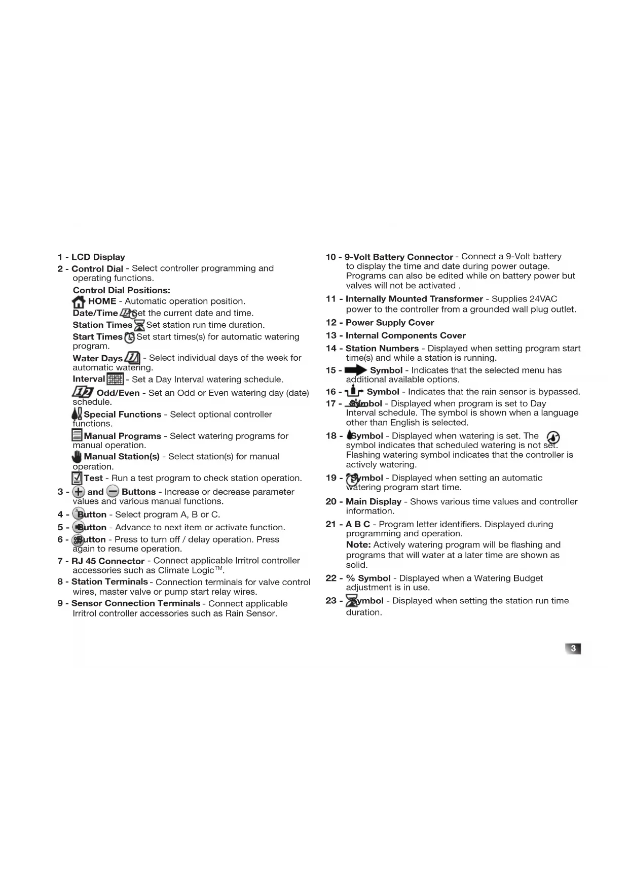
123456TODAY 789OFF → ABC % 151617 14 18 19 PM 202122 6123 4 5 7 8 9 10 11 12 131 - LCD Display
2 - Control Dial - Select controller programming and operating functions.
Control Dial Positions:
HOME - Automatic operation position.
Date/Time ☐Set the current date and time.
Station Times ☒ Set station run time duration.
Start Times Ⓧ Set start times(s) for automatic watering program.
Water Days 📂 - Select individual days of the week for automatic watering.
Interval - Set a Day Interval watering schedule.
12 Odd/Even - Set an Odd or Even watering day (date) schedule.
Special Functions - Select optional controller functions.
Manual Programs - Select watering programs for manual operation.
Manual Station(s) - Select station(s) for manual operation.
Test - Run a test program to check station operation.
3 - + and - Buttons - Increase or decrease parameter values and various manual functions.
4 - Button - Select program A, B or C.
5 - Button - Advance to next item or activate function.
6 - Button - Press to turn off / delay operation. Press again to resume operation.
7 - RJ 45 Connector - Connect applicable Irritrol controller accessories such as Climate Logic™.
8 - Station Terminals - Connection terminals for valve control wires, master valve or pump start relay wires.
9 - Sensor Connection Terminals - Connect applicable Irritrol controller accessories such as Rain Sensor.
10 - 9-Volt Battery Connector - Connect a 9-Volt battery to display the time and date during power outage. Programs can also be edited while on battery power but valves will not be activated.
11 - Internally Mounted Transformer - Supplies 24VAC power to the controller from a grounded wall plug outlet.
12 - Power Supply Cover
13 - Internal Components Cover
14 - Station Numbers - Displayed when setting program start time(s) and while a station is running.
15 - Symbol - Indicates that the selected menu has additional available options.
16 - Symbol - Indicates that the rain sensor is bypassed.
17 - Symbol - Displayed when program is set to Day Interval schedule. The symbol is shown when a language other than English is selected.
18 - Symbol - Displayed when watering is set. The symbol indicates that scheduled watering is not set. Flashing watering symbol indicates that the controller is actively watering.
19 - Symbol - Displayed when setting an automatic watering program start time.
20 - Main Display - Shows various time values and controller information.
21 - A B C - Program letter identifiers. Displayed during programming and operation.
Note: Actively watering program will be flashing and programs that will water at a later time are shown as solid.
22 - % Symbol - Displayed when a Watering Budget adjustment is in use.
23 - Symbol - Displayed when setting the station run time duration.
Controller Installation
Installing the Cabinet
-
For safe and reliable operation, select an installation site which can ideally provide the following conditions:
-
For Indoor model controllers – Inside a garage or other structure which will provide protection from the weather.
- For outdoor model controllers – Protection from irrigation spray, wind and snow. A shaded location is recommended.
- Access to a grounded AC power source (within 4' [1.2m] for indoor models) which is not controlled by a light switch or utilized by a high current load appliance, such as a refrigerator or air conditioner.
-
Access to the sprinkler control valve wiring and optional accessory wiring.
-
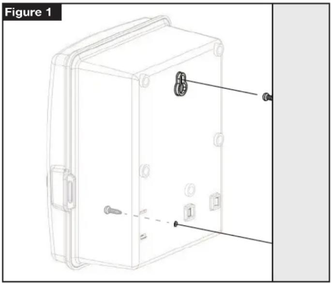
Drive a wood screw (provided) into the wall at eye level. Leave the screw extended approximately 1/4" (6mm) from the wall. See Figure 1.
Note: If installing the controller on drywall or masonry, install screw anchors. - Remove the lower cabinet access cover by pressing it on the bottom and pulling it directly outward from the cabinet.
- Hang the cabinet on the screw using the keyhole slot on the back panel. Make sure the cabinet slides down securely on the screw.
- Install the lower mounting screw and tighten securely.
Note: Conduit and adapters are not provided. Install conduit as required by local electrical codes.
- Remove the power wire access cover. Remove the conduit knockout according to the size of conduit being used. Install 1/2" (13mm) conduit for power/equipment ground wires (outdoor models only) and 3/4" (19mm) or 1" (26mm) conduit for valve wires (all models).
natural_image
Technical line drawing of a mechanical enclosure with screws and mounting holes, labeled as Figure 1 (no text or symbols on the diagram itself)Installing the Valves
CAUTION: Maximum screw torque not to exceed 5 in-lbs.
- Route the valve wires or wire cable from the valves, into the controller cabinet.
Note: 18AWG (1.0mm2) multi-wire sprinkler valve connection cable can be used. This cable is insulated for direct burial and is color-coded to simplify installation. It can be routed directly into the controller through the access hole provided for valve wire conduit (if conduit is not used). - Attach the white color-coded wire from the cable to one wire from each valve solenoid. (Either solenoid wire can be used for this connection.) This is called the "Valve Common" wire. See Figure 2.
- Attach a separate cable wire to the remaining wire from each valve solenoid. Note the wire color code used for each valve and the watering station it controls. You will need to have this information when connecting the valve wires to the controller.
- Secure all wire splices using wire nut connectors. To prevent corrosion and possible short circuits, always use an insulated wire nut, grease cap or similar waterproofing method.
- At the controller end of the valve connection cable, strip back 1/4" (6mm) of insulation from all cable wires
- Secure the Valve Common wire to the terminal labeled COM. Connect the individual valve wires to the appropriate station terminals. Connect the master valve wire (if applicable) to the terminal labeled MV.
Note: Connecting a master valve or pump start relay is optional and may not be required for your sprinkler system.
Installing a Pump Start Relay
CAUTION: To prevent controller damage, ensure the pump start relay current draw does not exceed 0.4A. Do not connect the pump motor starter directly to the controller.
- Connect a wire pair to the 24VAC pump start relay. Route the wires into the controller housing with the valve wires.
- Connect one wire to the terminal labeled COM. Connect the remaining wire to the terminal labeled MV. See Figure 2.
CAUTION: To prevent pump damage due to "Dead-heading," connect a jumper wire from any unused station terminal to a station terminal with a valve connected.
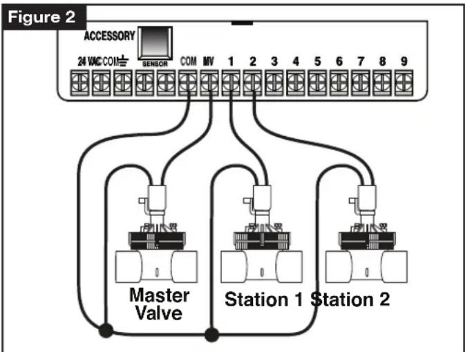
flowchart
graph TD
    A["ACCESSORY"] --> B["24 VAC COM"]
    B --> C["SENSOR"]
    C --> D["COM MV 1 2 3 4 5 6 7 8 9"]
    D --> E["Master Valve"]
    D --> F["Station 1"]
    D --> G["Station 2"]
Installing a Rain Sensor (optional)
A rain sensor can be connected directly to the KD2 to automatically interrupt watering when it begins to rain. When the rain sensor absorbs rain water, it automatically signals the KD2 to suspend all watering operations. The display will alternately show SEN (sensor) and the time of day until the rain sensor drys out and resets the controller for automatic operation.
- Route the wire cable from the rain switch sensor into the controller along with the valve wires.
- Remove the jumper wire from the sensor terminals.
-
Referring to the instructions provided with the rain sensor, connect two wires from the rain sensor designated for "Normally Closed" applications to the sensor terminals. See Figure 3.
-
Once powered, turn the dial to special Functions. Press and scroll to RS Y (Rain Sensor Yes). Press + / -to set sensor to RS Y (active) or RS N (Bypass).
Note: The default setting is RS Y (active).
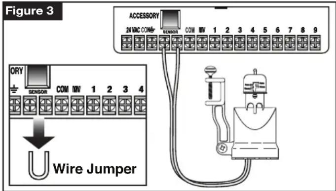
text_image
Figure 3 ACCESSORY 24 VMC COM- SENSOR COM MV 1 2 3 4 5 6 7 8 9 ORY SENSOR COM MV 1 2 3 4 U Wire JumperConnecting the Power Source
WARNING
AC power wiring must be installed and connected by qualified personnel only. All electrical components and installation procedures must comply with all applicable local and national electrical codes. Some codes may require a means of disconnection from the AC power source installed in the fixed wiring and having a contact separation of at least 0.120" (3mm) in the line and neutral poles. Make sure the power source is OFF prior to connecting the controller.
- Verify that the power is turned off at the source.
- Remove the power connection access cover.
- Route the power and equipment ground wires from the power source through conduit into the controller power connection compartment. For wire restraint, route the cable inside the compartment as shown in Figure 4 A.
Note: The international model terminal block accepts wire size up to 4 mm ^2 . - For non-US models, use the terminal block which accepts wire size up to 4 mm^2 (Brown for line, Blue for neutral and Green for earth ground). For US models, use the wire nuts provided, secure Line to the Black wire, Neutral to the White wire and Equipment Ground to the Green wire. See Figure 4 B and C.
-
Install and secure the power wire access cover.
-
Apply power to the controller. The controller needs about 60 seconds to internally charge before station outputs can operate. This will only occur when the controller is initially powered up or after a power interruption.
See Setting the Date and Time on page 7 to set the current time and date. To quickly check sprinkler system operation, refer to the Test Mode procedure.

text_image
Figure 4 AUS Model Non-US Model
Line - Black
Neutral - White
Earth Grnd - Green
Line - Brown
Neutral - Blue
Earth Grnd - Green
Programming
Note: To select an optional display language or clock format, refer to Display Language Option on page 18.
Setting the Date and Time
- Turn the control dial to the Date/Time Position.
- Adjust the clock to the current hour by pressing the + or + button.
Note: The display will change rapidly if either button is pressed for more than three consecutive seconds.
- Press the button to advance to the next field.
- Adjust the selected field by pressing the button.
- Repeat steps 3–4 to adjust the remaining fields of the Date/Time display.
- Return the control dial to HOME position when finished.
Planning Your Watering Schedule
It is often helpful to plan your watering schedule on paper before beginning the programming steps. The information can then be transferred to the Quick Reference Card as a handy reference.
Filling out the Watering Schedule Form
When filling out the form provided on page 10, use a pencil so changes can be easily made.
Refer to the example shown on the opposite page and fill out your form in a similar manner. Include the following information:
- Location - Identify the location of each watering station area and the type of plant being watered.
Note: Enter the following information for each program. If the program is not needed, leave its information column blank. - Watering Day Schedule - For a Calendar schedule, indicate which day(s) of the week watering is desired. For a Day Interval schedule indicate the desired Interval number (1–31). For Odd or Even day watering schedule, simply mark the appropriate box.
- Station Run Time Duration - Indicate the amount of run time (1 minute to 4 hours) for each station. Write "Off" for any station which you do not want to run in the program.
- Program Start Times - Indicate the time(s) of day to start the program. Each program can have up to three start times per watering day.
⚠️ Important: The KD2 can run only one program watering cycle at a time. Therefore, when setting more than one start time for a program or when setting up more than one program, make sure that each program watering cycle will be able to run completely before the next start time occurs. This can be easily determined by totaling up the run time duration of all stations that will operate during the program, then selecting the next start time that can accommodate the completion of the initial watering program. If Water Budget is used to increase run time duration, this must also be considered in the total run time. It is important to remember that a program start time which occurs while a watering cycle is in progress will be delayed (stacked) until the current watering cycle is finished. If this happens, it may appear that the sprinklers are not shutting off or that they are running at an unexpected time of day.
| Watering Schedule Form | Program A Program B Program C | ||||
| Watering Day Schedule | Calendar Days | ||||
| Interval | |||||
| Odd/Even | Odd □ Even □ | Odd □ Even Odd Even □ □ | |||
| Station | Location | Run Time Run Time | Run Time | ||
| 1 | Parkway Lawn | 10 min | Off | Off | |
| 2 | Front Lawn | 10 min | Off | Off | |
| 3 | Front Shrubs | Off | 5 min | Off | |
| 4 | Back Lawn | 25 min | Off | Off | |
| 5 | Garden | Off | Off | 1 hr | |
| 6 | |||||
| 7 | |||||
| 8 | |||||
| 9 | |||||
| Program Start Times | 1 | 5:00 AM | 4:00 AM | 6:00 AM | |
| 2 | Off | Off | Off | ||
| 3Day Interval | Off | Off | Off | ||
| Odd/Even | Odd □ Even □ | Odd □ Even Odd Even □ □ | |||
| Station | Location | Run Time Run Time | Run Time | ||
| 1 | |||||
| 2 | |||||
| 3 | |||||
| 4 | |||||
| 5 | |||||
| 6 | |||||
| 7 | |||||
| 8 | |||||
| 9 | |||||
| Program Start Times | 1 | ||||
| 2 | |||||
| 3 | |||||
About the KD2 Memory
The KD2 is equipped with non-volatile memory and will retain program information in the event that AC power is lost or no battery is connected. The date and time are maintained for up to 24-hours in the event that AC power is lost, but the user has the option of installing a 9-volt battery to maintain the date and time in the absence of AC power in excess of 24-hours.
Setting a Calendar Day Schedule
The Calendar Day schedule enables you to set each day of the week as an active or inactive watering day. Each day can be active or inactive in each program (A, B and C).
- Turn the control dial to Water Days position.
- Press the button as needed to select the desired program. Program letter A, B or C will be displayed.
- Press either the button to make the day active (the watering symbol is displayed) or inactive (the no-watering symbol is displayed) for the selected program.
- Press to advance to the next Water Day.
- Repeat steps 1 and 3 for each day of the week.
- Repeat steps 1–4 for each program as needed.
- Return the control dial to HOME position when finished.
Setting a Day Interval Schedule
A Day Interval schedule enables watering days to be set without regard to the actual days of the week. For example, a 1-day interval will water every day, a 2-day interval will water every other day and so on up to a 31-day interval, which will water only once a month. The active watering day is the last day of the Interval.
In order to establish a reference point for the beginning of the Day Interval, the current day within the interval is also entered. For example, if a 3-day interval is selected and “Today” is entered as day 2 of the interval, then watering will occur tomorrow (the last day of the interval).
- Turn the control dial to the Interval position.
- Press the button as needed to select the desired program. Program letter A, B or C will be displayed.
Note: If Odd or Even is displayed, an Odd/Even watering day schedule is already selected for the program and must first be made inactive before a Day Interval schedule can be used. Refer to “Setting An Odd/Even Day Schedule” for this procedure.
- Press the ☐ button to select the desired interval number (01–31). The letters DY (day) are displayed to the right of the Day Interval number.
- To remove an Interval schedule from the program, press the +r button to display -- -- -- (dashes).
- Press the button. TODAY or will be displayed.
- Use the + button to select the Today number designation. DY (day) is displayed to the left of the Today number.
- Repeat steps 2–5 for each program as needed.
- Return the control dial to HOME position when finished.
Note: To prevent watering on specific days of the week, regardless of schedule type; i.e., never water on Saturday, turn the control dial to the Water Days position and press to select Saturday. Press the on button to display the no-watering symbol
Setting an Odd or Even Day Schedule
Using an Odd or Even Day watering schedule enables either odd numbered days (1st, 3rd, etc.) or even numbered days (2nd, 4th, etc.) to be selected to water.
- Turn the control dial to the 0.5d/Even position .
- Press the button as needed to select the desired program. Program letter A, B or C will be displayed.
Note: If Int is displayed, a Day Interval watering schedule is already selected for the program and must first be made inactive before an Odd or Even day schedule can be selected. Refer to "Setting A Day Interval Schedule" on page 12 for this procedure.
- Press the +r button to display Odd or Even.
- To remove an Odd or Even Day schedule from the program, press the + button to display -- -- -- (dashes).
- Repeat steps 2 and 3 for each program as needed.
- Return the control dial to HOME position when finished.
Note: Since the first day of every month is an odd number, the last day of every month which is an odd number will not be active. This feature prevents two consecutive watering days from occurring.
Note: To prevent watering on specific days of the week, regardless of schedule type; i.e., never water on Saturday, turn the control dial to the Water Days position and press to select Saturday. Press the on button to display the no-watering symbol
Setting Program Start Time
The program start time is the time of day you select to begin an automatic watering program cycle. When a program starts, each station with a designated run time duration in the program will operate in numerical order, one station at a time. Sometimes it is necessary to run a watering program more than once per day. For example, when watering a new lawn. The KD2 provides three independent start times per day for each program. Refer to page 8 for additional program start time information
- Turn the control dial to Start Times Position. The start time being edited will be indicated at the top of the display. Press the ➕ to select a different start time (1, 2 or 3). The start time symbol will be displayed in the lower left corner.
- Press the button as needed to select the desired program. Program letter A, B or C will be displayed.
- Set the start time by pressing the +r button.
Note: The display will change rapidly if either button is pressed for more than three consecutive seconds.
- To remove a start time, press the +or button to display -- -- -- (dashes). The dashes are shown as the clock display passes from 5:59 AM, 11:59 AM, 5:59 PM and 11:59 PM (05:59, 11:59, 17:59 and 23:59).
- Press the ⚠️ to advance to the next start time.
- Repeat steps 1 and 3 for each additional start time.
- Repeat steps 1–4 for each program as needed.
- Return the control dial to HOME position when finished.
Setting Station Run Time Duration
The station run time duration is the amount of time a station will operate once it has been started. A station is assigned to a program when it is given a designated run time duration ranging from 1 minute to 4 hours. Each station can have a different run time duration in each program.
Note: You have the option to view station run time duration in minutes only or in hours and minutes. By default, the run time will be displayed in the minutes format; i.e., 1 hour and 30 minutes is displayed as 90M (minutes). To select the alternate format, refer to “Station Run Time Duration Format Option”.
- Turn the control dial to Station Times ☑ position. The selected station number and the station run time duration symbol ☑ will be displayed.
- Press the button as needed to select the desired program. Program letter A, B or C will be displayed.
- Adjust the station run time duration by pressing the + or + button.
- To remove the station from the program, decrease the run time duration to less than 1 minute to display -- -- -- (dashes).
- Press the 📄 to advance to the next station.
- Repeat steps 1 and 3 to set the run time duration for each station as needed for the selected program.
- Repeat steps 1–4 for each program as needed.
- Return the control dial to HOME position when finished.
Controller Operation
The KD2 controller has five modes of operation:
Automatic, Manual Station(s), Manual Programs, Test and Off. In the Automatic mode, the controller tracks the time and day and operates the automatic watering schedules as programmed. The Manual Station(s) mode enables an individual station or group of stations to be started and controlled manually. Manual Programs mode enables watering programs to be started manually. Test mode enables a quick, temporary program to be run to test the operation of each station control valve. The Off mode prevents all station operation.
Automatic Operation
Automatic operation will occur whenever the programmed start time and watering day matches the KD2's internal clock and calendar.
The HOME control dial position is the normal position for the dial when automatic operation is desired. However, the controller will operate automatically when the control dial is in any position.
While an automatic watering program is running and the control dial is in the HOME position, pressing the button will manually advance from the activate station to the next displayed station number in sequence
Manual Operation
Manual controller operations will override all currently active automatic operation and sensor input. Any automatic program start time that occurs during a manual operation will be delayed until the manual operation is terminated or concluded. Any automatic program delayed past midnight will be postponed.
True Manual Operation
True manual operation allows a single station to be selected and run without regard to run time duration. Once started, the station will run until it is turned off or the controller clock time passes midnight.
- Turn the control dial to 🎨Manual Station position.
- Press the button until the desired station number is flashing and the display shows -- -- -- (dashes).
- Press the button once to activate the station. The station number and ON will be displayed along with the flashing watering symbol. Leave the dial in the Manual Station position. The station will remain on until operation is terminated or until midnight.
- To terminate operation prior to midnight, turn the control dial to any other position or press any button.
- Return the control dial to HOME position when finished.
Timed Manual Operation
Timed manual operation enables any stations to be given a temporary station run time duration and operated in sequence.
- Turn the control dial to 🏠 Manual Station position.
- Press the button until the desired station number is flashing and the display shows -- -- -- (dashes).
- Press ☐ turn the station ON. The station will remain active until the control dial is moved or another station is selected.
For a specific run time (from 1 minute to 4 hours), continue to press +Once the run time is set, press ➤ to activate.
Note: The temporary station run time will not affect the station's run time within any automatic program.
- Repeat steps 2–4 to select additional stations. (These stations will not start immediately, but will operate in sequence.)
-
After all desired stations for timed manual operation have been selected, return the control dial to HOME position.
-
To manually advance through the station sequence, press the button (the control dial must be in the HOME position to use this feature).
- To terminate the timed manual operation, either skip through the remaining station sequence with the ➕ button, or press the ➕ button. OFF will be displayed. Press ➕ button again to resume automatic watering.
Manual Program Operation
Manual program operation enables automatic watering programs to be manually started and operated in sequence.
- Turn the control dial to the Manual Programs position. The display will show MAN, the currently selected program letter and stations assigned to the program.
- Press the button as needed to display a program you wish to run. All stations which currently have a station run time duration assigned to the selected program will be shown at the top of the display.
- Press the button to start the program (or select an additional program). The program letter and the watering symbol will begin flashing.
- Repeat steps 2 and 3 to select additional programs to operate in sequence.
- Return the control dial to HOME position. The remaining run time duration for the currently operating station will be displayed. Station numbers and programs waiting to run will also be shown.
- To manually advance through the station sequence, for the program, press the button. If more than one program was selected, continue pressing the button to advance to the next program in sequence.
- To terminate the manual program operation, either skip through the remaining stations and programs in sequence with the ➕ button, or press the 🔊 button. OFF will be displayed. Press 🔊 button again to resume automatic watering.
Test Mode
Selecting this function enables you to run a quick, temporary watering program to test the operation of each watering station.
Note: While in Home display, you can terminate test mode by pressing the button. OFF will be displayed. Pressing the button again will resume automatic watering.
You can also press the ➕ button to advance to the last station.
-
Turn the control dial to the ☑ Test position. The display will show 2M for a 2-minute run time for each station.
-
Press the +r button to change the run time from 1 to 9 minutes if desired.
Note: The run time used in the test program is temporary and will not alter the station run time set for automatic program operation. The test run time is also based on the clock time so if a station is given a test time of 1-minute and was set 15 seconds before the minute changes, it will only run for 15 seconds and when the minute increments, the next station will start.
-
Press the button to start the test.
-
Return the control dial to HOME position. The watering symbol 🔊 and the operating station number will be flashing. The remaining station numbers to be tested will be displayed. As the test time is completed for each station, the station number disappears and the next station in sequence starts.
- By leaving the dial in the HOME position, the controller completes the test of each station then returns to the Automatic mode.
- To advance to the next station in sequence, press the button while in the Home display. Advancing past the last station will end the test program.
Rain Delay Mode
This feature enables all automatic watering operations to be delayed from 1 to 7 days. When the number of delay days elapses, the controller returns to automatic operation.
-
Turn the control dial to the HOME position.
-
Press the 🔊 button.
-
Press the button to select the desired number of rain delay days (1-7). The number will be displayed with OFF; i.e. OFF 2 for a 2-day delay.
- The controller will automatically reactivate after the rain delay is complete. The rain delay days are decremented at midnight and will reactivate the controller after the last day is complete.
- To terminate the rain delay operation at any time, repeat steps 1–3 to display OFF.
Turning Off the KD2
When the button is pressed, OFF will be displayed. Any watering operation currently in progress will be turned off and programmed automatic operation will be prevented.
The KD2 controller will remain off until the button is pressed again to resume normal operation.
Special Functions
The Special Functions dial position provides access to various control features and optional display formats. The special functions are: Water Budget, Station Run Time Duration Format Option, Display Language Option, Clock Time Format Option, Program Erase, Enable/Disable Expansion Port, Sensor Bypass and Firmware Version.
Water Budget
Water Budget enables you to conveniently decrease or increase the run time duration currently set for each station assigned to a selected program. The adjustment can be made in 10% increments from 0% (displayed as OFF) to 200% of the normal (100%) run time.
Note: Water Budget is applied to programs A, B and C independently. For example, applying Water Budget to program A will not alter the run time duration of any stations assigned to Program B or C.
- Turn the control dial to Special Functions position.
- Press the button as needed to select the desired program. The currently set percentage for the program will be displayed.
-
Press the button to select the desired adjustment percentage; i.e., 90% equals a 10% reduction of station run time and 200% doubles the station run time.
-
To apply Water Budget to another program, repeat steps 2 and 3.
- Return the control dial to HOME position when finished.
Note: During operation, the display will show the adjusted run time for each station as it starts running. As a reminder of Water Budget setting (other than 100%), the % symbol will be displayed with the current time.
Station Run Time Duration Format Option
The station run time duration can be displayed in either minutes or hours and minutes format. To change the current run time format, use the following procedure:
- Turn the control dial to Special Functions position.
- Press the button as needed to display MMM or HH:MM.
- Press the + button to select the desired format: MMM = minutes; i.e., 1 hour and 30 minutes is displayed as 90M.
HH:MM = hours and minutes; i.e., 1 hour and 30 minutes is displayed as 1:30.
- Return the control dial to HOME position when finished.
Display Language Option
Various display information can be viewed in any of the three languages: English, Spanish and French. To change the display language, use the following procedure:
-
Turn the control dial to the Special Functions position.
-
Press the button as needed to display ENG.
-
Press the +r button to select the desired language: ESP (Spanish) or FRA (French).
-
Turn the control dial to the HOME position when finished.
Time Format Option
Time of day can be displayed in either 12-hour AM/PM or 24-hour format.
-
Turn the control dial to the Special Functions position.
-
Press the button as needed to select the clock time format option designated by 12H or 24H.
-
Press the +r button to display the desired format.
-
Return the control dial to HOME position when finished.
Program Erase
The Program Erase feature enables you to easily clear the controller memory of all program start times, station run time duration and water budget information for a selected program or all programs without changing the current time, date and language option.
-
Turn the control dial to the Special Functions position.
-
Press the button as needed to display CLR.
-
Program A will be displayed. If needed, press the button once to select program B. Press the button again to select program C. Pressing the button again selects programs A, B and C.
-
Press the +buton to display the program letter(s) and OK?. Press the -button to cancel.
-
Press the + button to clear the program(s) (CLR will be displayed).
-
Repeat steps 3–5 to clear any remaining program(s) as needed.
-
Return the control dial to HOME position when finished.
Enable/Disable Expansion Port
Your KD2 controller is compatible with many of Irritrol's controller enhancement products like the Climate Logic™ Weather Sensing System (CL-100-WIRELESS) and the Climate Logic™ Hand-Held Remote (R-100-KIT) by way of the built-in expansion port. The provided expansion port for Climate Logic™ devices must be switched ON to enable operation. See item 7 on page 2 for the location of the expansion port. The expansion port is switched ON by default when assembled at the factory.
- Turn control dial to Special Functions position.
- Press the button as needed to select the expansion port switch option designated by XP N.
- Press the ☐ button to select Y (yes, expansion port on), or N (expansion port off).
- Return the control dial to HOME position when finished.
Enable/Disable Rain Sensor Terminals
To utilize the sensor terminals, RS must be set to Y. Selecting N will bypass the sensor terminals and the controller will function normally regardless of the input at the sensor terminals.
- Turn control dial to Special Functions position.
- Press the button as needed to select RS N.
- Press the +r button to select Y (yes) to enable or N (no) to disable sensor inputs.
- Return the control dial to HOME position when finished.
Firmware Version
To check your KD2's firmware version, place the control dial to 🖱️ Special Functions position and press the ➕ button as needed until the firmware version is displayed (V001 or later).
Automatic Circuit Breaker
The KD2 controller features an electronic circuit breaker which automatically detects an overload condition on a station terminal during operation and turns off the station before controller damage can occur. The KD2 advances to the next programmed station in sequence to continue the watering cycle.
After the program watering cycle has finished, FUSE and the number of the skipped station(s) will be displayed in alternating sequence with the current time of day. If all of the station numbers and FUSE are displayed, the master valve is malfunctioning. Pressing any button will remove the warning display.
⚠️ Important: The most common cause of an overload condition is a short circuit in the valve wiring or a malfunctioning valve solenoid. The cause of the overload condition should be corrected before continuing to operate the controller.
Troubleshooting
| Symptom | Probable Cause | Remedy |
| Display is blank and controller does not operate. | Power is disconnected. | Check transformer connections (indoor models). Check the AC service panel for a tripped circuit breaker or GFI and reset. |
| Valve does not turn on. | Faulty control valve wire connections.Sensor switch in Active position without a sensor or jumper installed.No station run time duration set. | Check the wire connections at control valve and controller.Set sensor switch to Bypass position or add jumper to sensor terminals.Check station run times. See page 12. |
| Valve does not turn off. | Control valve problem | Inspect, clean and/or replace the valve solenoid and/or diaphragm. |
| Watering program(s) start at unexpected times. | Watering program schedules have overlapping start times.Water Budget setting over 100% can cause delayed start times. | Check program start time schedules.Shorten station run times and/or space start times farther apart.Check Water Budget and decrease adjustment % factor as necessary. |
| Controller not watering on the selected active day. | Rain Delay is active.Interval or Odd/Even Mode. | Check if Rain Delay is set.Check if Interval or Odd/Even mode is selected and see if the selected day falls within the Odd, Even or falls between the interval watering schedule. |
Electromagnetic Compatibility
Domestic: This equipment has been tested and found to comply with the limits for a Class B digital device, pursuant to Part 15 of the FCC Rules. These limits are designed to provide reasonable protection against harmful interference in a residential installation. This equipment generates, uses and can radiate radio frequency energy and, if not installed and used in accordance with the instructions, may cause harmful interference to radio communications. However, there is no guarantee that interference will not occur in a particular installation. If this equipment does harmful interference to radio or television reception, which can be determined by turning the equipment off and on, the user is encouraged to try to correct the interference by one or more of the following measures:
- Reorient or relocate the receiving antenna.
- Increase the separation between the equipment and receiver.
- Connect the equipment into an outlet on a circuit different from that to which the receiver is connected.
- Consult the dealer or an experienced radio/TV technician for help.
International: This is a CISPR 22 Class B product.
Technical Assistance Information
For Technical Assistance:
USA -(909) 785-3623, (800) 634-8873
Australia - 1300 130 898