GBTS 1100 - Grinder Güde - Free user manual and instructions
Find the device manual for free GBTS 1100 Güde in PDF.

User questions about GBTS 1100 Güde
0 question about this device. Answer the ones you know or ask your own.
Ask a new question about this device
Download the instructions for your Grinder in PDF format for free! Find your manual GBTS 1100 - Güde and take your electronic device back in hand. On this page are published all the documents necessary for the use of your device. GBTS 1100 by Güde.
USER MANUAL GBTS 1100 Güde
Translation of the original instructions Belt- and disc sander
natural_image
3D rendering of a machine with blue and black components, no visible text or symbols
GBTS 1100
38352
GÜDE GmbH & Co. KG
Birkichstrasse 6
74549 Wolpertshausen
Deutschland

Güde


ENGLISH Please read the instructions carefully before starting the machine.
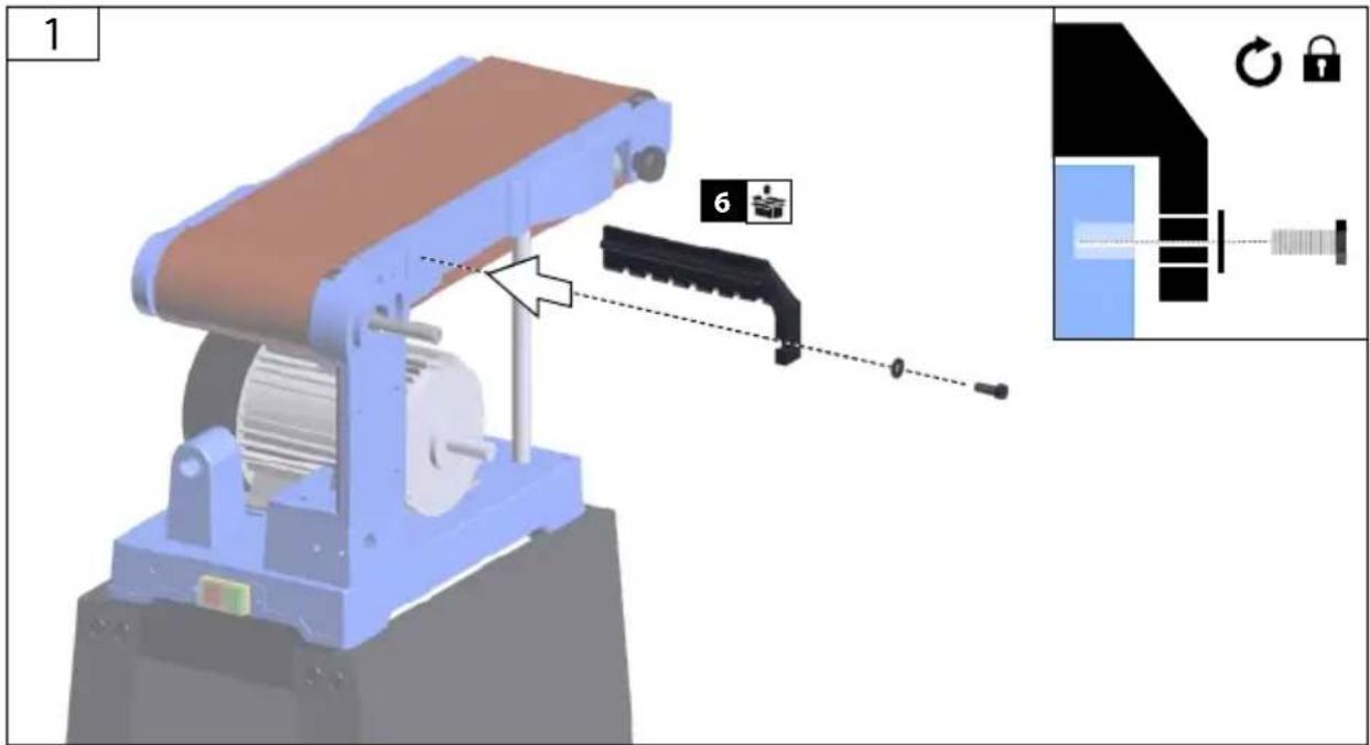
text_image
Scanned document page with Chinese text and a 3D model illustration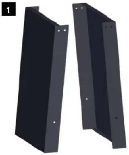
natural_image
Two black metal-framed panels with mounting holes, shown from different angles (no text or symbols)
text_image
2 x 8 3 x 4 4 x 4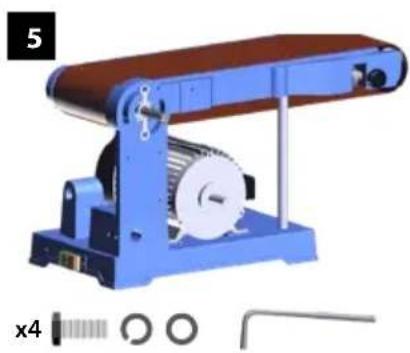
natural_image
Mechanical device with conveyor belt and gear mechanism (no visible text or symbols)
natural_image
Black mechanical part with cutouts and a circular hole, labeled '11' and 'x 4' (no text or symbols on the part itself)


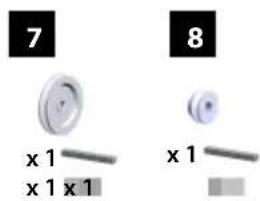
text_image
7 x 1 x 1 x 1 8 x 1
natural_image
Black plastic object with a small protrusion and a scale bar, labeled '14' and 'x 6' (no text or symbols on the object itself)
natural_image
Black rectangular electronic device with metal legs and wheels, labeled '15' in top-left corner (no other text or symbols)


natural_image
Two black rectangular objects with a circular lens-like feature, one larger and one smaller, next to a scale bar (no text or symbols)DE Montage
EN Assembly
FR Assemblage
IT Montaggio
NL Montage
CS Montáž
SK Montáž
HU Szerelés
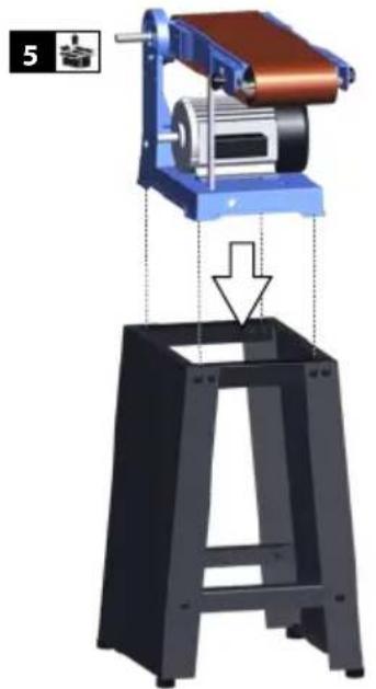
1
2-10
DE Inbetriebnahme
EN Starting-up the machine
FR mise en service
text_image
Technical diagram showing 3D mechanical assembly with labeled components and step-by-step assembly instructionsDE Montage
EN Assembly
FR Montage
IT Montaggio
NL Montage
CS Montáž
SK Montáž
HU Szerelés


4
natural_image
Mechanical assembly diagram showing a motor lifting a black stand with a downward arrow indicating force or motion (no text or symbols present)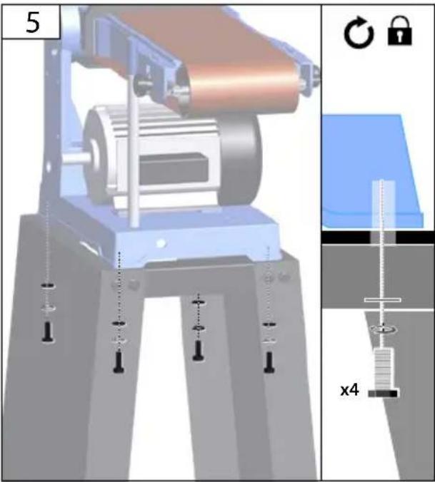
natural_image
Mechanical assembly diagram showing a roller on a platform with mounting holes and a close-up of a spring scale (no text or symbols)1
natural_image
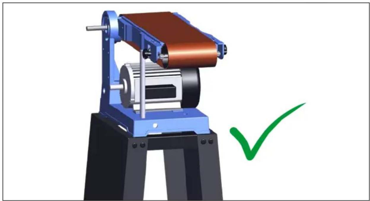
3D mechanical device with a copper coil and motor, marked with a green checkmark (no text or symbols on the device itself)| 1 | DE Montage |
| EN Assembly | |
| FR Montage | |
| IT Montaggio | |
| NL Montage | |
| CS Montáž | |
| SK Montáž | |
| HU Szerelés |

text_image
1 6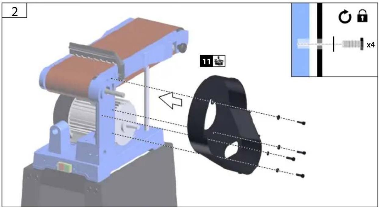
text_image
2 11 x4DE Montage
EN Assembly
FR Montage
IT Montaggio
NL Montage
CS Montáž
SK Montáž
HU Szerelés


text_image
3 7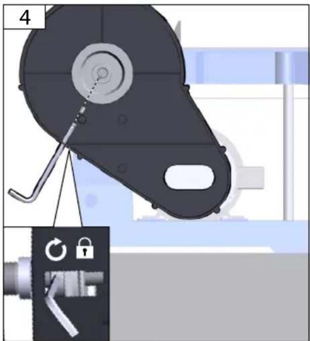
text_image
4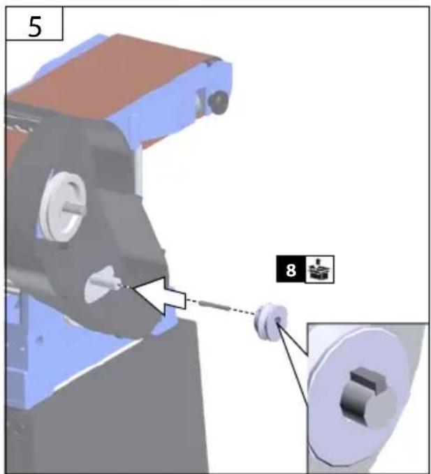
text_image
5 8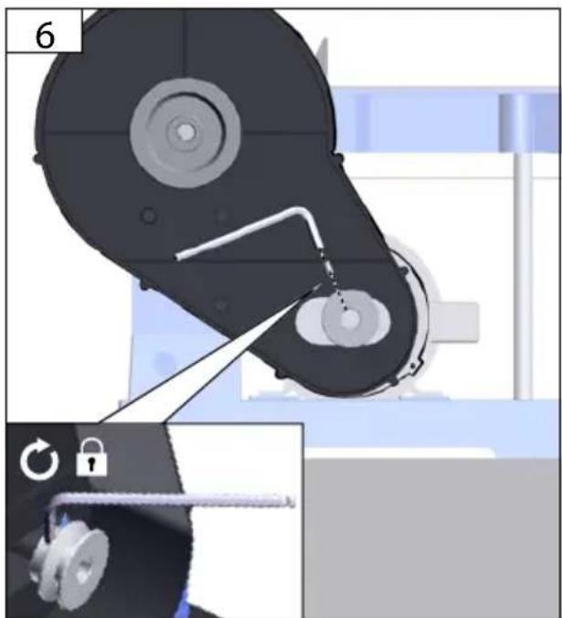
natural_image
Mechanical assembly diagram showing a pulley system with a lock mechanism, no text or symbols present| 1 | DE Montage |
| EN Assembly | |
| FR Montage | |
| IT Montaggio | |
| NL Montage | |
| CS Montáž | |
| SK Montáž | |
| HU Szerelés |

text_image
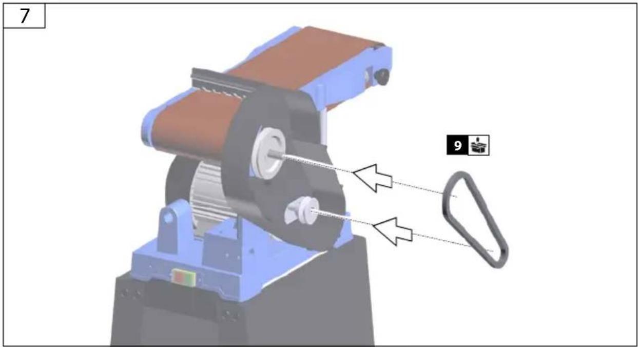
7 9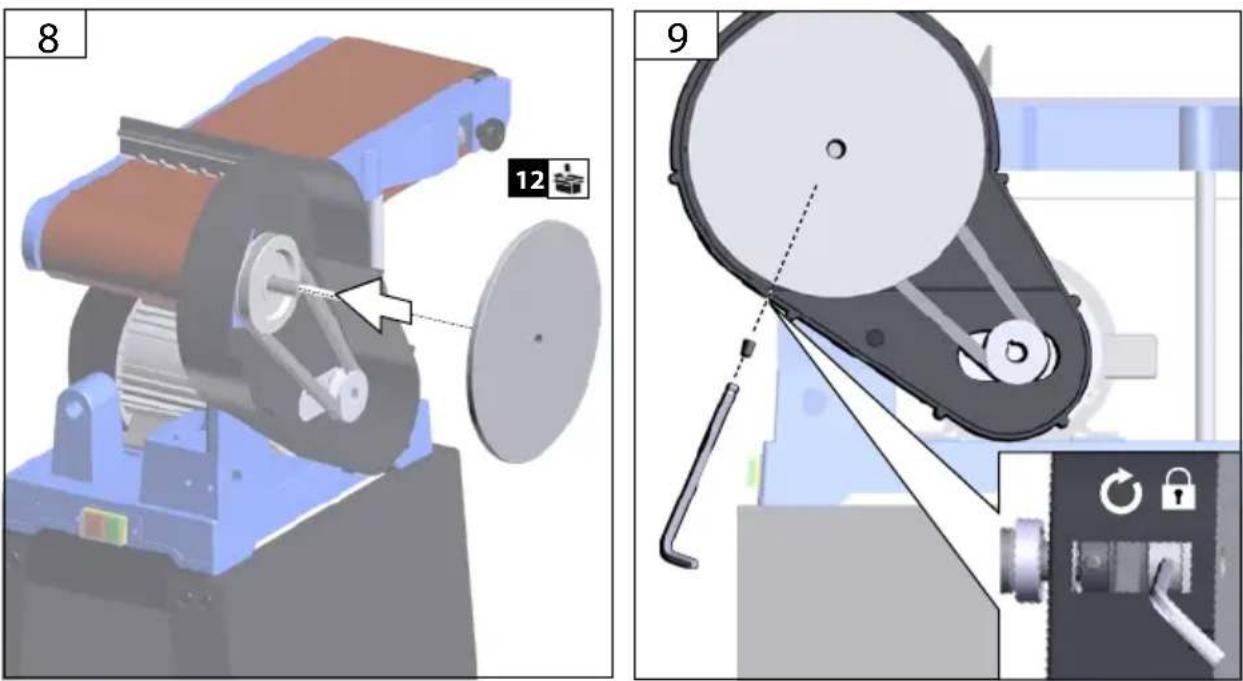
text_image
8 12 9DE Montage
EN Assembly
FR Montage
IT Montaggio
NL Montage
CS Montáž
SK Montáž
HU Szerelés

10
natural_image
3D mechanical assembly diagram showing a rollerblading machine with a red circular component, no visible text or symbols11

text_image
14 x6| 1 | DE | Montage |
| EN | Assembly | |
| FR | Montage | |
| IT | Montaggio | |
| NL | Montage | |
| CS | Montáž | |
| SK | Montáž | |
| HU | Szerelés |

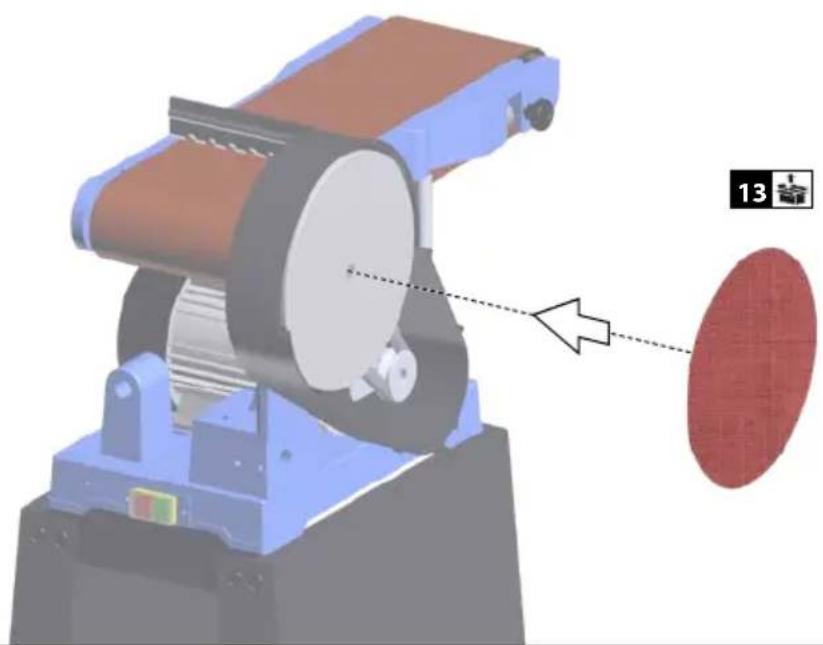
text_image
12 15 16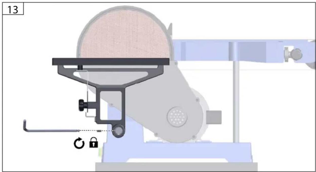
natural_image
Technical illustration of a mechanical device with labeled parts (no readable text or symbols)DE Montage
EN Assembly
FR Montage
IT Montaggio
NL Montage
CS Montáž
SK Montáž
HU Szerelés

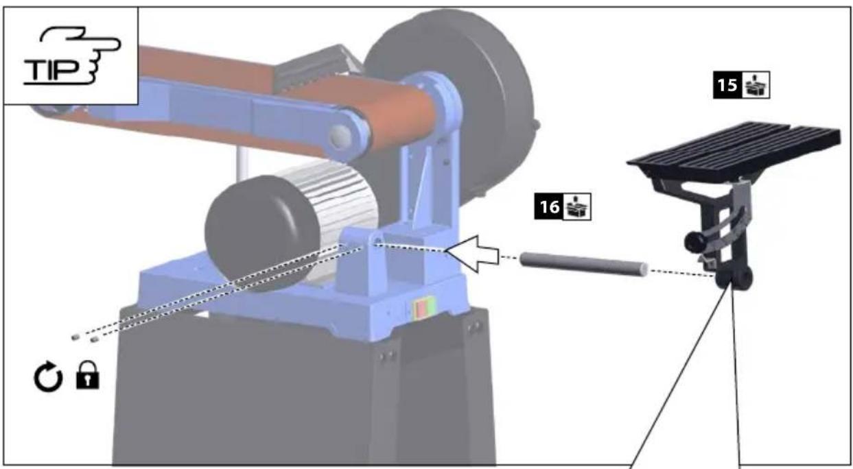
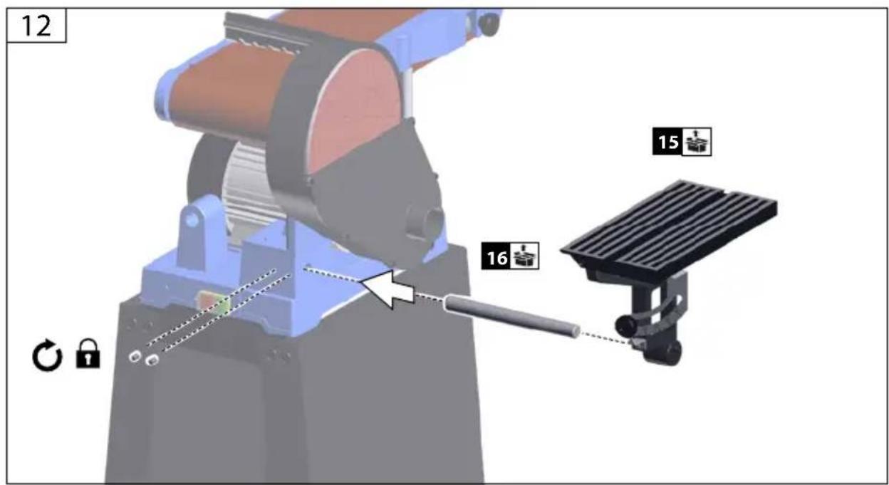
text_image
TIP 15 16 16
natural_image
Mechanical assembly diagram showing a presser with lock and rotation indicator (no text or symbols)| 1 | DE | Montage |
| EN | Assembly | |
| FR | Montage | |
| IT | Montaggio | |
| NL | Montage | |
| CS | Montáž | |
| SK | Montáž | |
| HU | Szerelés |

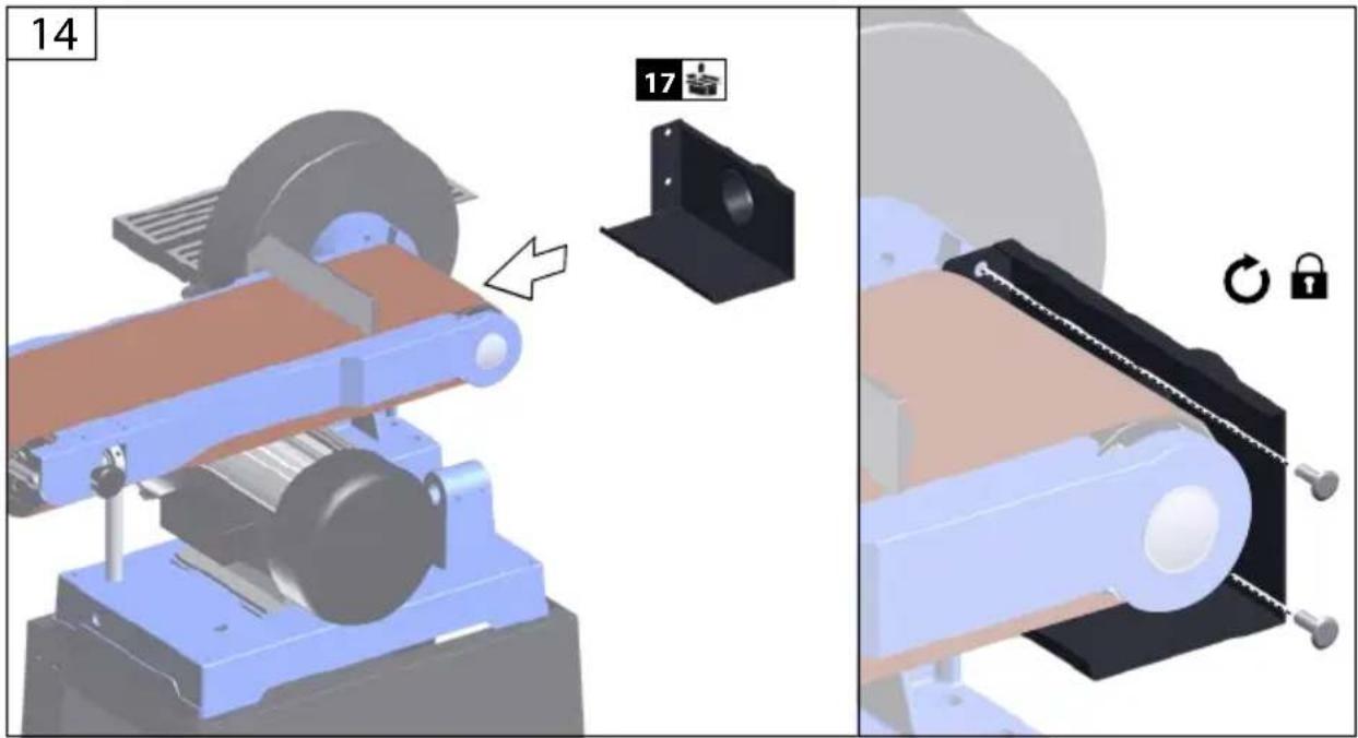
text_image
14 17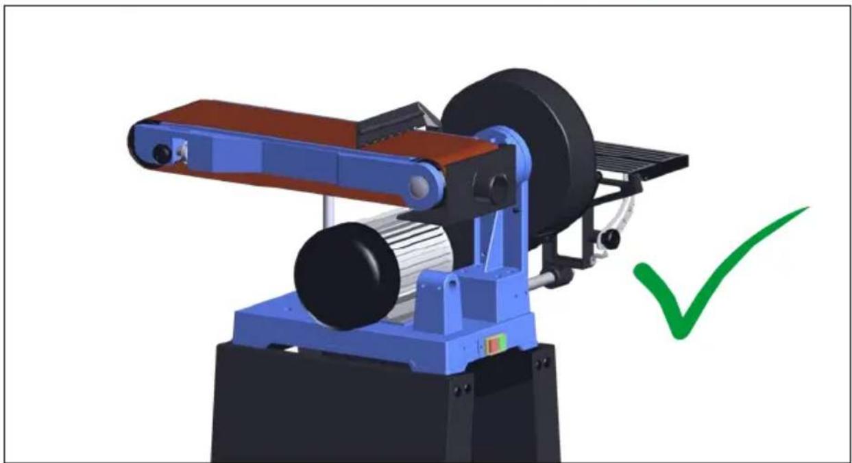
natural_image
3D rendering of a mechanical machine with conveyor belt and wheel, marked with a green checkmark (no text or symbols)DE Inbetriebnahme
EN Starting-up the machine
FR mise en service
IT Messa in funzione
NL Inbedrijfstelling
CS Uvedení do provozu
SK Uvedenie do prevádzky
HU Üzembe helyezés
2

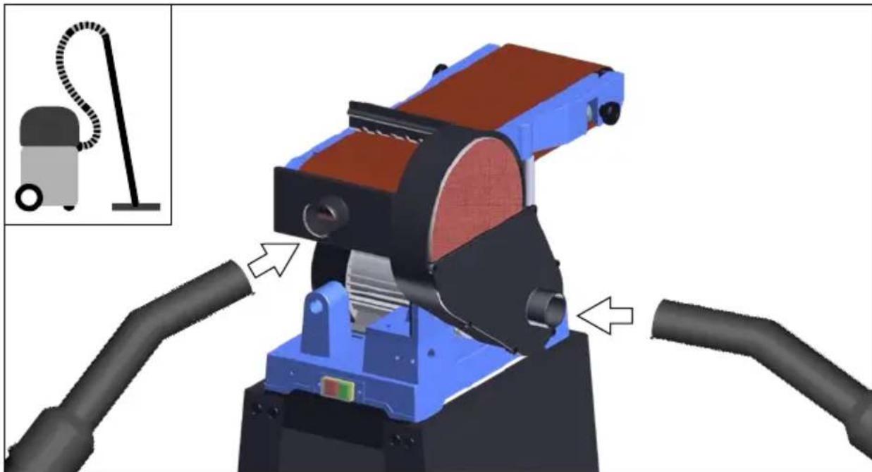
natural_image
3D rendering of a mechanical device with pipe connections and a vacuum cleaner inset (no text or symbols)2
DE Inbetriebnahme
EN Starting-up the machine
FR mise en service
natural_image
3D rendering of a mechanical machine with conveyor belt and roller, no visible text or symbolsDE Inbetriebnahme
EN Starting-up the machine
FR mise en service
IT Messa in funzione
NL Inbedrijfstelling
CS Uvedení do provozu
SK Uvedenie do prevádzky
HU Üzembe helyezés
2

1
text_image
Technical diagram showing a conveyor belt system with labeled components and a close-up of a mechanical component with a circular icon.2
text_image
Diagram of a mechanical device with labeled parts and directional arrows, including a lock icon and numbered annotations.2
DE Inbetriebnahme
EN Starting-up the machine
FR mise en service
natural_image
3D rendering of a conveyor belt system with a green checkmark indicating inspection (no text or symbols on the diagram itself)DE Inbetriebnahme
EN Starting-up the machine
FR mise en service
IT Messa in funzione
NL Inbedrijfstelling
CS Uvedení do provozu
SK Uvedenie do prevádzky
HU Üzembe helyezés
2

text_image
Technical diagram showing a machine tool with labeled parts and directional arrows indicating motion or assembly.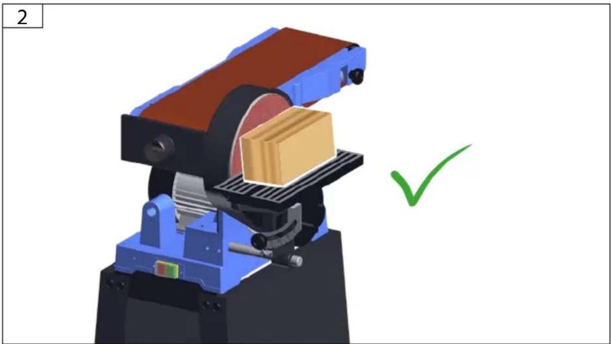
natural_image
3D mechanical assembly diagram with a green checkmark indicating inspection or completion (no text or symbols present)
3
DE Betrieb
EN Operation
FR Fonctionnement
IT Esercizio
NL Gebruik
CS Provoz
SK Prevádzka
HU Üzemeltetés


START
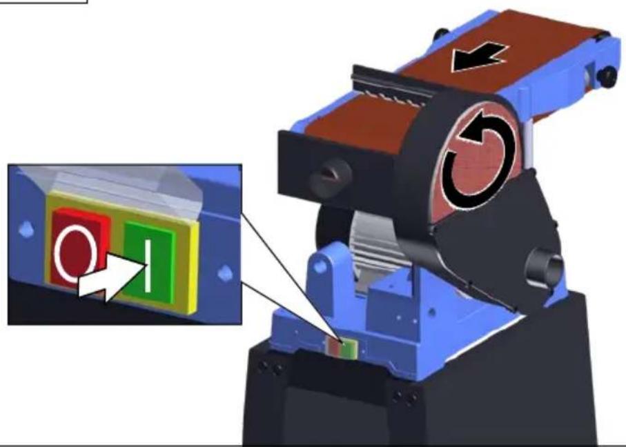
natural_image
3D mechanical assembly with a highlighted control panel and directional arrows (no text or symbols)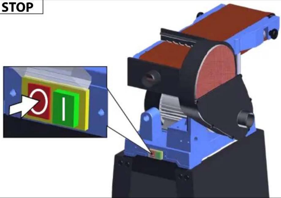
text_image
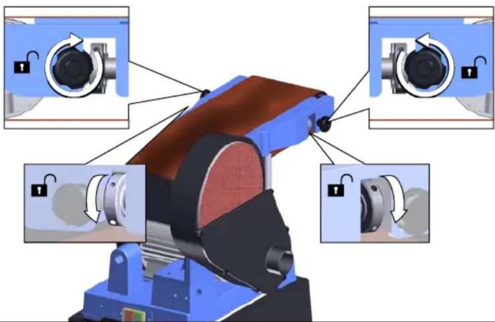
STOPDE Schleifband wechseln
EN Changing the sanding belt
FR Changer la bande abrasive
IT Sostituire il nastro abrasivo
NL Schuurband vervangen
CS Výměna brusného pásu
SK Výmena brusného pásu
HU Karbantartás
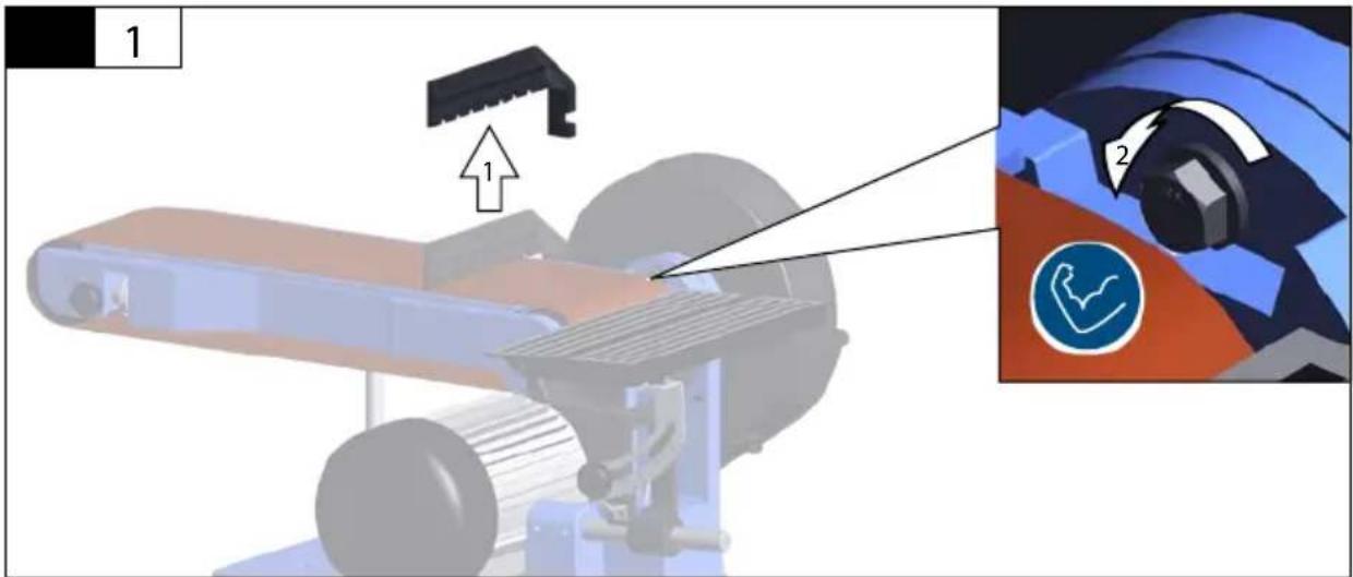
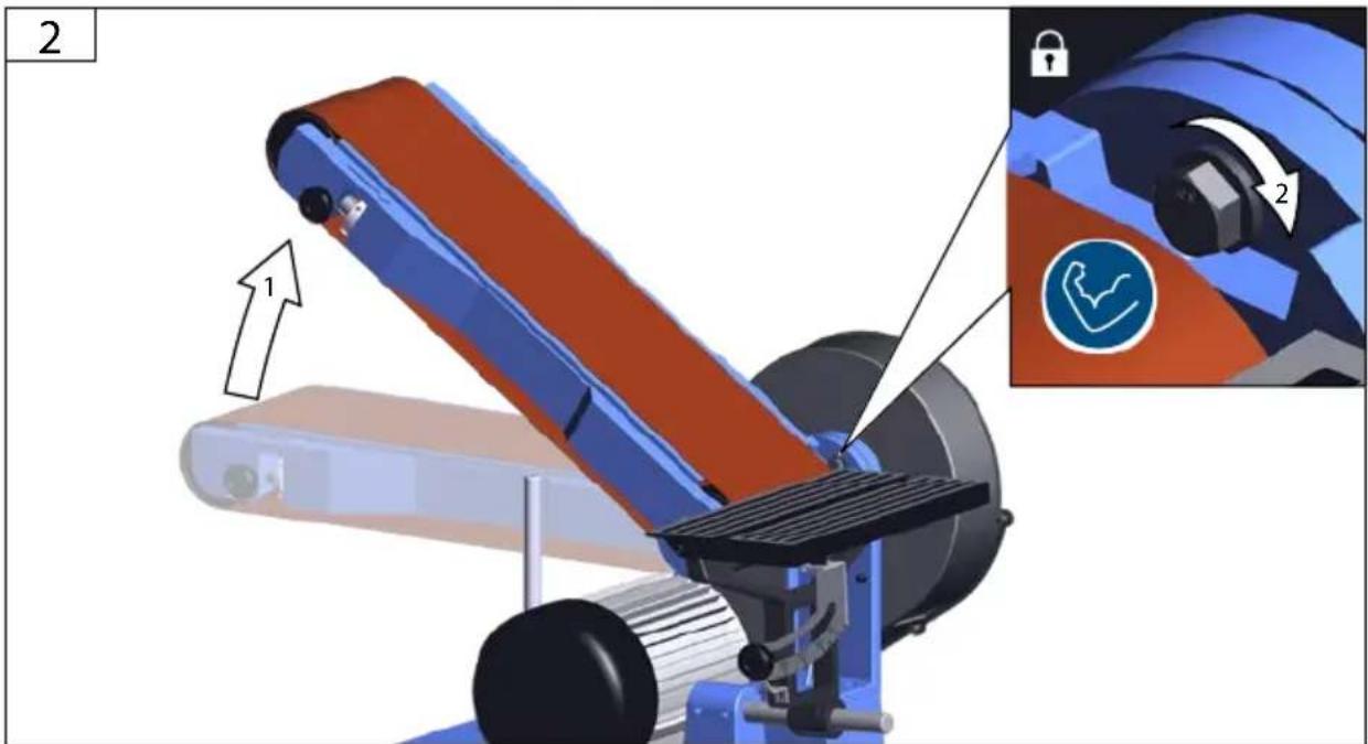
4


1
text_image
Technical diagram of a mechanical device with labeled components and directional arrows indicating rotation or adjustment.2
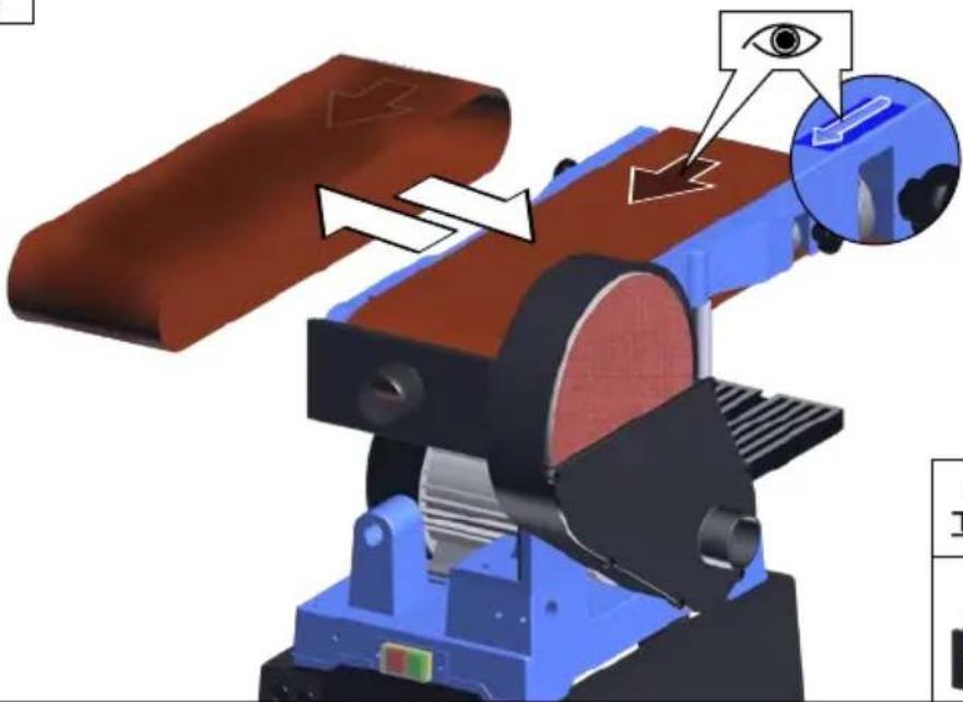
natural_image
3D mechanical assembly diagram showing a grinding machine with a brown component and an eye indicator (no text or symbols)
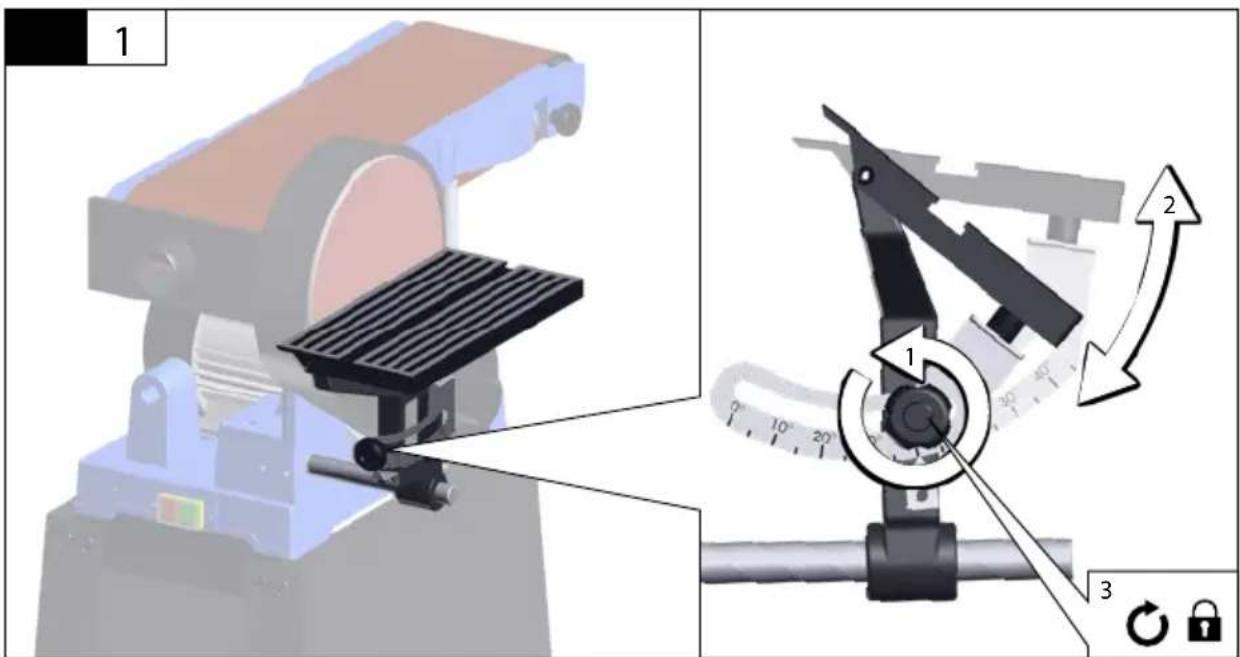
text_image
TIP | DE | Schleifband ausrichten |
| EN | Aligning the sanding belt | |
| FR | Aligner la bande abrasive | |
| IT | Allineare il nastro abrasivo | |
| NL | Schuurband uitlijnen | |
| CS | Vyrovnání brusného pásu | |
| SK | Vyrovnanie brusného pásu | |
| HU | Csiszolószalag beállítása |


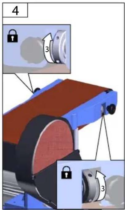
text_image
4 3 3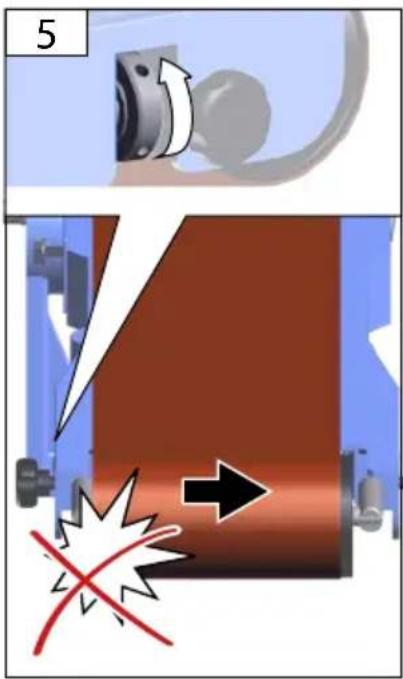
text_image
5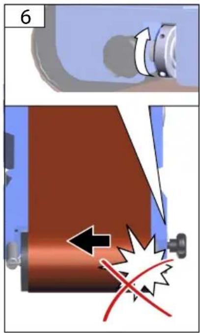
text_image
6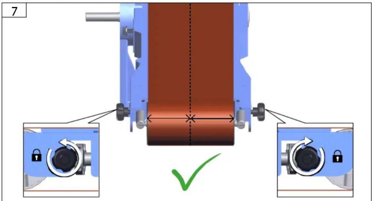
text_image
7Technische Daten
| Belt- and disc sander GBTS 1100 | |
| Art. No 38352 | |
| Rated voltage 230 V | |
| Rated frequency ~ 50 Hz | |
| Rated input 1100 W | |
| No-load speed 1500 min | -1 |
| Degree of protection | IP XO |
| Belt speed 5,8 m/s | |
| Belt size 1219 x 152 mm | |
| Sanding surface max. | 375 x 152 mm/∅ 230 mm |
| Velcro sanding disc | |
| Dimensions L x W x H | 665 x 450 x 455 mm |
| Weight 40 kg | |
| Noise details | |
| Sound pressure level L_pA | 75,6 dB (A) |
| Sound power level L_WA | 78,4 dB (A) |
| Measured according to EN61029; Uncertainty K = 3 dB (A) | |
| Wear ear protectors! | |
The declared vibration total value(s) and the declared noise emission value(s) have been measured in accordance with a standard test method and may be used for comparing one tool with another.
The declared vibration total value(s) and the declared noise emission value(s) may also be used in a preliminary assessment of exposure.
The vibration and noise emissions during actual use of the power tool can differ from the declared values depending on the ways in which the tool is used especially what kind of workpiece is processed.
Identify safety measures to protect the operator that are based on an estimation of exposure in the actual conditions of use (taking account of all parts of the operating cycle such as the times when the tool is switched off and when it is running idle in addition to the trigger time).


Read and understand the operating instructions before using the appliance. Familiarise with the
control elements and how to use the appliance properly. Abide by all the safety measures stated in the service manual. Act responsibly toward third parties.
The operator is responsible for accidents or risks to third parties.
Persons over 16 years of age can only work on the appliance. An exception includes youngsters trained in order to reach knowledge under supervision of the trainer during occupational education.
In case of any doubts about connection and operation refer please to our customer center
Specified Conditions Of Use
This equipment is exclusively intended for surface processing and deburring wood or wood-like materials, as well as ferrous metals and non-ferrous metals, while taking the maximum sanding surface and safety regulations into consideration.
The machine may only be used in a technically perfect condition and taking into account all safety information.
Do not use this product in any other way as stated for normal use. Not observing general regulations in force and instructions from this manual does not make the manufacturer liable for damages.
⚠ It is strictly prohibited to disassemble, modify and purposely remove the protective equipment on the unit and fit other protective equipment instead.
Residual risks
Even when the device is used properly and all safety regulations are complied with, there still may be some residual risks.
- noise emissions
- dust emissions
• vibrations to hand and arms - Danger of burns
Tool and workpiece heat up during operation. - Risk of injury
Sharp tools and workpiece edges
Emergency procedure
Conduct a first-aid procedure adequate to the injury and summon qualified medical attendance as quickly as possible. Protect the injured person from further harm and calm them down. If you seek help, state the following pieces of information: 1. Accident site, 2. Accident type, 3. Number of injured persons, 4. Injury type(s)
Symbols

WARNING/CAUTION!

WARNING - Read the operating instructions to reduce the risk of injury.

Unplug the machine before any work on it.

Wear eye protective goggles!
Wear ear protectors!

Wear a suitable dust protection mask.

Safety shoes to be used
Any damaged or disposed electric or electronic devices must be delivered to appropriate collection centres.

CE marking
General Power Tool Safety Warnings
WARNING Read all safety warnings, instructions, illustrations and specifications provided with this power tool. Failure to follow all instructions listed below may result in electric shock, fire and/or serious injury.
Save all warnings and instructions for future reference.
The term „power tool“ in the warnings refers to your mains-operated (corded) power tool or battery-operated (cordless) power tool.
1) Work area safety
a) Keep work area clean and well lit. Cluttered or dark areas invite accidents.
b) Do not operate power tools in explosive atmospheres, such as in the presence of flammable liquids, gases or dust. Power tools create sparks which may ignite the dust or fumes.
c) Keep children and bystanders away while operating a power tool. Distractions can cause you to lose control.
2) Electrical safety
a) Power tool plugs must match the outlet. Never modify the plug in any way. Do not use any adapter plugs with earthed (grounded) power tools. Unmodified plugs and matching outlets will reduce risk of electric shock.
b) Avoid body contact with earthed or grounded surfaces, such as pipes, radiators, ranges and refrigerators. There is an increased risk of electric shock if your body is earthed or grounded.
c) Do not expose power tools to rain or wet conditions. Water entering a power tool will increase the risk of electric shock.
d) Do not abuse the cord. Never use the cord for carrying, pulling or unplugging the power tool. Keep cord away from heat, oil, sharp edges or moving parts. Damaged or entangled cords increase the risk of electric shock.
e) When operating a power tool outdoors, use an extension cord suitable for outdoor use. Use of a cord suitable for outdoor use reduces the risk of electric shock.
f) If operating a power tool in a damp location is unavoidable, use a residual current device (RCD) protected supply. Use of an RCD reduces the risk of electric shock.
3) Personal safety
a) Stay alert, watch what you are doing and use common sense when operating a power tool. Do not use a power tool while you are tired or under the influence of drugs, alcohol or medication. A moment of inattention while operating power tools may result in serious personal injury.
b) Use personal protective equipment. Always wear eye protection. Protective equipment such as dust mask, non-skid safety shoes, hard hat, or hearing protection used for appropriate conditions will reduce personal injuries.
c) Prevent unintentional starting. Ensure the switch is in the off-position before connecting to power source and/or battery pack, picking up or carrying the tool. Carrying power tools with your finger on the switch or energising power tools that have the switch on invites accidents.
d) Remove any adjusting key or wrench before turning the power tool on. A wrench or a key left attached to a rotating part of the power tool may result in personal injury.
e) Do not overreach. Keep proper footing and balance at all times. This enables better control of the power tool in unexpected situations.
f) Dress properly. Do not wear loose clothing or jewellery. Keep your hair and clothing away from moving parts. Loose clothes, jewellery or long hair can be caught in moving parts.
g) If devices are provided for the connection of dust extraction and collection facilities, ensure these are connected and properly used. Use of dust collection can reduce dust-related hazards.
h) Do not let familiarity gained from frequent use of tools allow you to become complacent and ignore tool safety principles. A careless action can cause severe injury within a fraction of a second.
4) Power tool use and care
a) Do not force the power tool. Use the correct power tool for your application. The correct power tool will do the job better and safer at the rate for which it was designed.
b) Do not use the power tool if the switch does not turn it on and off. Any power tool that cannot be controlled with the switch is dangerous and must be repaired.
c) Disconnect the plug from the power source and/or remove the battery pack, if detachable, from the power tool before making any adjustments, changing accessories, or storing power tools. Such preventive safety measures reduce the risk of starting the power tool accidentally.
d) Store idle power tools out of the reach of children and do not allow persons unfamiliar with the power tool or these instructions to operate the power tool. Power tools are dangerous in the hands of untrained users.
e) Maintain power tools and accessories. Check for misalignment or binding of moving parts, breakage of parts and any other condition that may affect the power tool's operation. If damaged, have the power tool repaired before use. Many accidents are caused by poorly maintained power tools.
f) Keep cutting tools sharp and clean. Properly maintained cutting tools with sharp cutting edges are less likely to bind and are easier to control.
g) Use the power tool, accessories and tool bits etc. in accordance with these instructions, taking into account the working conditions and the work to be performed. Use of the power tool for operations different from those intended could result in a hazardous situation.
h) Keep handles and grasping surfaces dry, clean and free from oil and grease. Slippery handles and grasping surfaces do not allow for safe handling and control of the tool in unexpected situations.
5) Service
a) Have your power tool serviced by a qualified repair person using only identical replacement parts. This will ensure that the safety of the power tool is maintained.
Risk of injury!
Keep body parts and clothes away from rotating parts of the device.
The machine must be secured to the floor using suitable screws since otherwise there is a risk that it will tip over.
Carry out a visual inspection before switching the appliance on.
Check especially the safety equipment, electrical control elements, power lines and screw couplings for any damage and if they are tightened appropriately. If necessary, replace damaged parts before operation.
In the event of a blockage, switch off the machine immediately. Pull out the mains plug and remove the jammed workpiece.
Chips and splinters must not be removed while the machine is running.
Mains Connection
Operation is only allowed with a safety switch against stray current (RCD max. stray current of 30mA).
Connect only to a single-phase AC current supply and only to the mains voltage specified on the rating plate. Must only be used from sockets with earth wire.
Only plug-in when machine is switched off.
Maintenance
⚠️ Unplug the machine before any work on it.
The appliance must not be used if damaged or safety equipment is defective. Replace any worn-out and damaged parts.
Caution! If the power cord of the appliance gets damaged, it must be replaced by the manufacturer or its customer service or a similarly qualified person to avoid danger.
Repairs and works specified in these Instructions may only be performed by qualified authorised staff.
Use only original accessories and original spare parts.
Keep the device, in particular the air vents, clean at all times. Never spray water on the device body!
Do not clean the plastics with solvents, flammable or toxic fluids. For cleaning, use a damp cloth only.
Apply environment-friendly oil to all moving parts.
Only a regularly maintained and treated appliance can serve as a satisfactory aid. Insufficient maintenance and care can lead to unforeseen accidents and injuries.
If necessary, a list of spare parts can be found at www.guede.com.
Guarantee
Warranty period of 12 months applies to commercial use and 24 months applies to private use and commences on the day of purchase of the device.
The guarantee solely covers inadequacies caused by material defect or manufacturing defect. Original payment voucher with the sales date needs to be submitted for any claim in the guarantee period.
The guarantee does not cover any unauthorised use such as appliance overloading, use of violence, damage as a result of any unauthorised interference or caused by foreign items. Failing to follow the operating and assembly instructions and common wear are also not included in the guarantee.
Important information for the customer
Please be sure to know that returning the product in or after the warranty period must be made in the original packaging.
Service
Do you have any technical questions? Any claim? Do you need any spare parts or operating instructions? We will quickly help you and without needles bureaucracy at our web pages at www.guede.com in the Servicing part. Please help us be able to help you. In order to identify your device in case of claim we need the serial No., product No. and year of production. All this data can be found on the type label.
Tel.: +49 (0) 79 04 / 700-360
Fax: +49 (0) 79 04 / 700-51999
E-Mail: support@ts.guede.com
WAARSCHUWING/OPGELET!

Translation of the EC-Declaration of Conformity
We, hereby declare the conception and construction of the below mentioned appliances correspond - at the type of construction being launched - to appropriate basic safety and hygienic requirements of EC Directives.
In case of any change to the appliance not discussed with us the Declaration expires.
Name: TUV Rheinland LGA Products GmbH Adress: Nallystrasse 2 90431 Nürnberg Germany
Type Ex. Cert.-No.:
97/68/EC
Emission No.:
□2000/14/EC_2005/88/EC