VBI7360WLWH - Fridge VIKING - Free user manual and instructions
Find the device manual for free VBI7360WLWH VIKING in PDF.
Download the instructions for your Fridge in PDF format for free! Find your manual VBI7360WLWH - VIKING and take your electronic device back in hand. On this page are published all the documents necessary for the use of your device. VBI7360WLWH by VIKING.
USER MANUAL VBI7360WLWH VIKING
Appliance is top heavy and tips easily when not completely installed. Keep doors closed until appliance is completely installed and secured per installation instructions. Use two or more people to move and install appliance. Failure to do so can result in death or serious injury. 8-18 x 1/2” Heater Fasteners (Item 7) Rear Connecting Plate (Item 5) Top Connecting Plate (Item 4) 1/4”-20 x 3/4” Connecting Plate Fasteners (Item 6) Heater (Item 1) Center Trim Brackets (Item 2) Center Trim (Item 3)3 Cutout Dimensions Can be located on either side 84” (213.4 cm) min.opening height85-3/16”(216.3cm) max.opening height *Refer to Specification chart for specific Models 25” (63.5 cm) Electric Outlet Location Water Line Entry Area
leveling dimension *Note: For all models, 3” back from the front of the cabinet on both sides needs to be nished like the outside of the cabinets
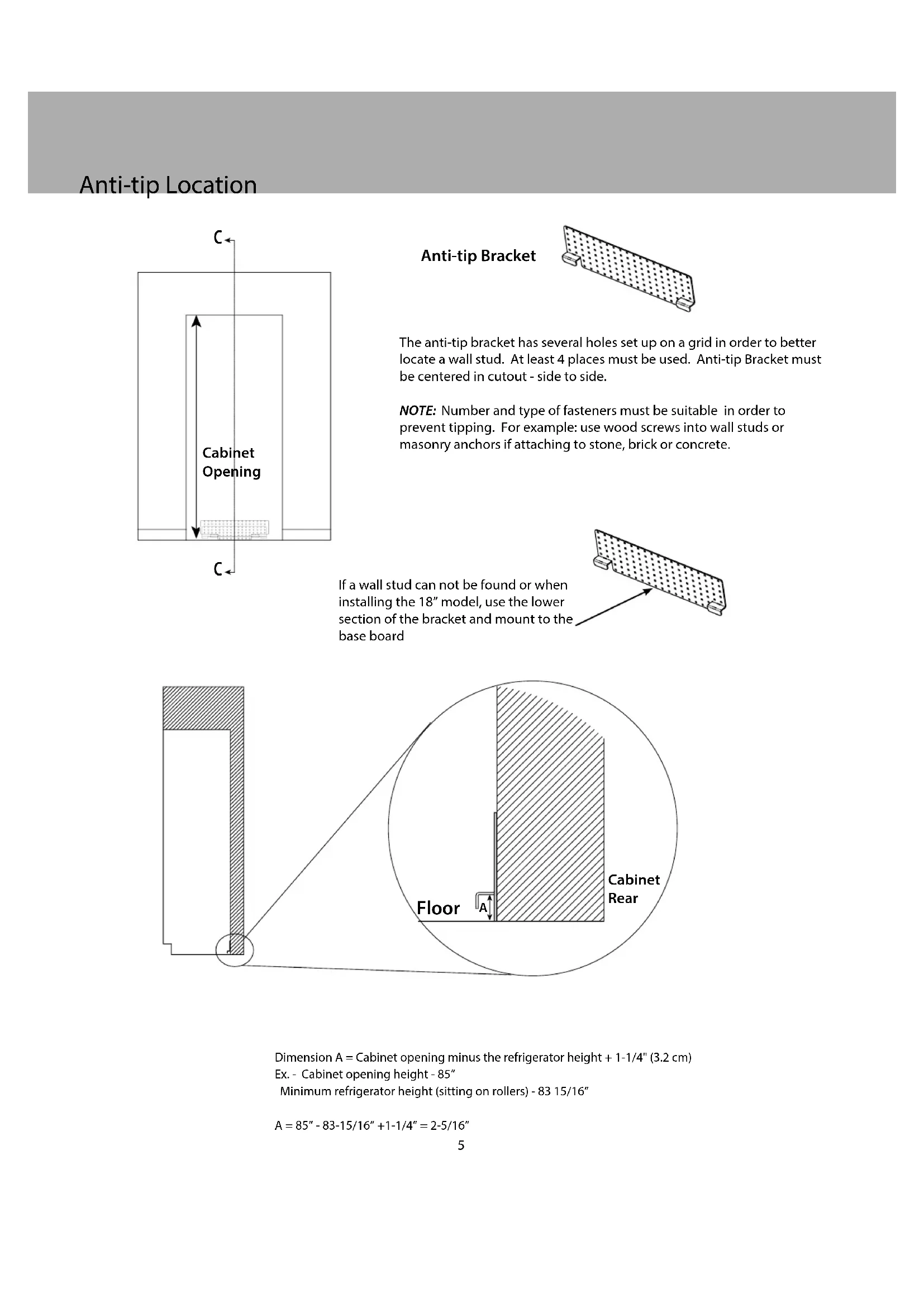
Cabinet Opening Dimension A = Cabinet opening minus the refrigerator height + 1-1/4" (3.2 cm)Ex. - Cabinet opening height - 85” Minimum refrigerator height (sitting on rollers) - 83 15/16”A = 85” - 83-15/16” +1-1/4” = 2-5/16” Anti-tip Bracket The anti-tip bracket has several holes set up on a grid in order to better locate a wall stud. At least 4 places must be used. Anti-tip Bracket must be centered in cutout - side to side. NOTE: Number and type of fasteners must be suitable in order to prevent tipping. For example: use wood screws into wall studs or masonry anchors if attaching to stone, brick or concrete. If a wall stud can not be found or when installing the 18” model, use the lower section of the bracket and mount to the base board6 Preparing Units for Installation Before removing units from pallet, remove the side trim from each unit, install center trim brackets and connection heater (steps 1 thru 4). Make sure units are unplugged and powered o . Look closely at the trim already installed on the unit. If the trim resembles that in Trim A, it will need to be removed and replaced with Trim B. If the trim already resembles Trim B, leave as is.
Preparing Units for Installation 3. Fasten heater (Item #1) to the three mounting holes on top of the right hand unit using the #8-18 x 1/2” fasteners (Item #7) provided.
4. Plug heater terminal into right hand unit using the plug located next to the unit on/o switch.8
Installation WARNING TIP OVER HAZARD Appliance is top heavy and tips easily when not completely installed. Keep doors closed until appliance is completely installed and secured per installation instructions.Use two or more people to move and install appliance. Failure to do so can result in death or serious injury.
5. Remove units from pallets and position together
outside of the cabinet so that top connecting plate (Item #4) can be installed. If installing on uneven surfaces, use unit leveling feet to adjust units to that they are at the same height.
7. Fasten rear connecting plate (Item #5) to the
threaded mounting holes provided on the rear of the unit using the 1/4”-20 x 3/4” (Item #6) fasteners. DO NOT install using a drill. Use manual allen wrench. (See Illustration B). Loosely attach the bracket allowing it to pivot. Tightening the screws will result in the bracket bending and causing misalignment of the rear of the units.
6. Install top connecting plate to the threaded
mounting holes provided on the top of the cabinet using the 1/4”-20 x 3/4” (Item #6) fasteners. DO NOT install using a drill. Use manual allen wrench. (See Illustration A)
Note: *If one or both units have (4) screw holes, attach using the top two holes.9 Installation 8. If unit leveling feet were used, lower units back onto rollers. Plug in electrical supply and roll connected units into cabinet cutout. Units must be plugged into separate electric outlets. Connect water supply to each unit. 9. Lift units to desired height using 5/16” socket and hand ratchet. DO NOT USE A DRILL-(refer to lift pattern diagram below to ensure that units are gradually lifted together.) **IMPORTANT** - Only make 4 turns at a time with the hand ratchet**. Attach units to cabinet side trim and fasteners included with the units. Install stainless magnetic side trim once fastened. (Use installation guide included with individual units as a reference.) .125” WHEN INSTALLED