CP4T - Speaker KLIPSCH - Free user manual and instructions
Find the device manual for free CP4T KLIPSCH in PDF.
| Technical Features | 4-inch ceiling speaker, 70V/100V, 8W power |
|---|---|
| Usage | Ideal for commercial and residential installations, background sound system |
| Maintenance and Repair | Regularly check connections, recommended grille cleaning |
| Safety | Installation compliant with electrical standards, avoid exposure to moisture |
| General Information | Compatible with 70V/100V audio systems, discreet design |
Frequently Asked Questions - CP4T KLIPSCH
Download the instructions for your Speaker in PDF format for free! Find your manual CP4T - KLIPSCH and take your electronic device back in hand. On this page are published all the documents necessary for the use of your device. CP4T by KLIPSCH.
USER MANUAL CP4T KLIPSCH
BEFORE DRILLING PILOT HOLES! To mount speaker HORIZONTALLY UP in ceiling/wall corner putting bracket on wall put THIS SIDE on wall flush against ceiling and mark horizontal pilot holes To mount speaker vertically in corner PUTTING BRACKET ON LEFT WALL against corner put THIS SIDE flush in corner on left wall and mark vertical pilot holesTo mount speaker vertically in corner PUTTING BRACKET ON RIGHT WALL against corner put THIS SIDE flush in corner on left wall and mark vertical pilot holes CP-T SERIES Thank you for your purchase of the Klipsch CP-T Series 70/100 Volt speakers! They are designed to both withstand the rigors of outdoor use while also complimenting any indoor décor. The 90°x 90° horn dispersion pattern assures wide, even coverage with either horizontal or vertical placement. The long-throw woofers are combined with front-firing ports for tight, musical bass no matter how they are mounted or placed. The included, unique speaker bracket allows for not only quick vertical or horizontal mounting but also allows for tight, wall/wall or wall/ceiling corner mounting for a highly aesthetic look that allows for increased overall bass output. The CP-4T contains a high quality, built-in 70/100 Volt transformer with a single, fixed 5/10 watt tap while the CP-6T contains a 70/100 Volt transformer with multiple tap settings of 3.75/7.5 watts, 7.5/15 watts, 15/30 watts and 30 watt taps. The CP-6T also has an 8 ohm bypass setting for 8 ohm operation.SPEAKER DIMENSIONS WITH/WITHOUT INCLUDED BRACKETS CP-4T CP-6T Tools/Parts Needed For Installation: a) A level b) A pencil c) A Philips #2 screwdriver or Phillips #2 bit with a drill with a LOW TORQUE SETTING d) Two #10 or #12 2.5-3 inch (4-5cm) Pan Head Screws for each speaker for mounting into wall stud OR minimum 10 lb. (5 kg) Wall Anchors for mounting if stud unavailable e) (If using Safety Cables) One 1” (2.5cm) long, 1/4”- 20-thread screw for each speaker
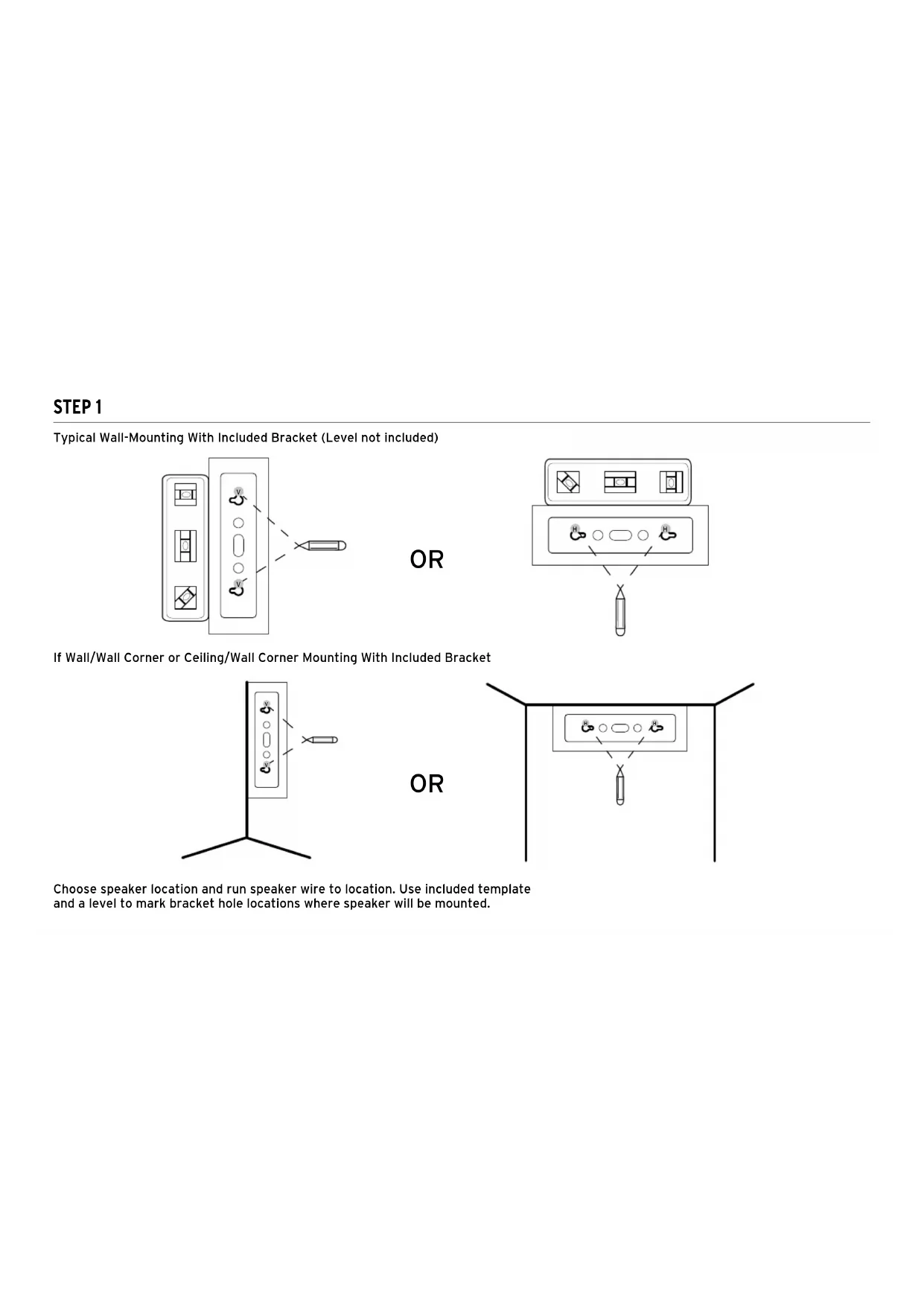
Choose speaker location and run speaker wire to location. Use included template and a level to mark bracket hole locations where speaker will be mounted. Typical Wall-Mounting With Included Bracket (Level not included) If Wall/Wall Corner or Ceiling/Wall Corner Mounting With Included Bracket
H H ORSTEP 2 Run speaker wire (and Safety Cable if used) through hole in bracket back and attach wall bracket to wall.
Speaker Wires Safety Cable (if desired or required) Use #10-#12, 2.5-3 INCH Pan Head ScrewsSTEP 3 Remove front terminal cover then slide speaker partially onto mounted bracket arms. Channel speaker wire from rear slot through front opening while keeping speaker in position with hand. Terminal CoverOR STEP 4 To keep speaker on bracket while adjusting use Phillips head screwdriver (or drill/screwdriver bit AT LOW TORQUE SETTING) and partially screw in front top/bottom bracket screws (2-3 revolutions) then gently pull out speaker to detente position 3/4ths of way on bracket.
IF USING A SPEAKER SAFETY CABLE
Attach it with a 1” (2.5cm) 20-thread screw (not included) to either threaded insert on speaker rear. Use a LOW TORQUE setting if drill and screwdriver bit are used. ORSTEP 5 Speaker Wires
45˚ 45˚ 45˚ WALL 45˚
With speaker still loosely on bracket arms, adjust speaker to desired angle on wall. MOUNTING OPTIONS 45˚ 45˚ 45˚ WALL 45˚
45˚ 45˚ 45˚ WALL 45˚
45˚ 45˚ 45˚ WALL 45˚
45˚ 45˚ 45˚ WALL 45˚
ORSTEP 6 Connect speaker wires to terminals (in parallel with all speakers) with Phillips screwdriver or LOW TORQUE drill/bit.
Select desired wattage tap setting on speaker front for either 70 or 100 Volt operation.STEP 7 STEP 8 Once speaker is positioned as desired push back all the way back on bracket arms until flush with bracket caps and screw two partially inserted screws all the way in to lock position. TEST SOUND: Play music/test signal through speaker to make sure connections are tight, and, IF USING CP-6T, tap setting is correct for desired volume.STEP 9 Once speaker is in the final position and tested, attach grill by pressing grill into channel encircling speaker front *SPEAKER GRILL REMOVAL: Use included grill removal tool, insert into a top corner and gently pull out. Repeat on a corner next to first one pulled, then pull out grill gently with hand. NOTE: the grill is designed to fit snug on speaker to both remain on and to remain tight. Continued removal/reinsertion of grill may make it loose and subject to either vibration or slippage.
USING A DIFFERENT MOUNTING BRACKET
All CP Series speakers have a 1/4”, 20-thread insert on the back bottom that you can attach a different, compatible mount. There is an additional 1/4”, 20-thread insert a safety cable can be mounted to.
Paint speaker and bracket top/ bottom caps separately.
1. First, clean speaker cabinet
and bracket top/bottom caps with mild solvent or mild detergent/water
2. Then create a paint mask for
speaker front (baffle) by tracing speaker grill on sheet of thicker, non-porous paper then cutting paper around tracing.
3. Place grill paper mask on front
of speaker (over baffle) making sure to also cover grill channel; secure with double sided tape. Do not put tape on woofer. Mask around bracket top/bottom caps making sure not to paint bracket arm and swivel mechanism. Mask logo on grill front.
4. Use a spray paint that is made
for plastic and spray speaker cabinet, bracket caps and grill front. Make sure not to cover grill holes. Allow all parts to dry before re-assembling speaker.CONNECTION
7.5 Watts7.5 Watts7.5 Watts
Wire from amp to first speaker, then from first to second speaker, then from second to third speaker, etc. (“Daisy Chain” wiring). ALWAYS WIRE IN PARALLEL IN A 70 OR 100 V SYSTEM! CP-6T Connection Example Total System Wattage = Spk1 Tapped Watts + Spk2 Tapped Watts + Spk3 Tapped Watts +……. It is recommended to add 50% additional wattage for the best sound and future system expansion Total System Wattage = 7.5 + 7.5 + 7.5 + 7.5 + 7.5 + 7.5 + 7.5 + 7.5 + 7.5 + 7.5 To t a l Sys t e m Wa t t a g e = 75 w a t t s A d d 5 0 % A d d i t i o n a l W a t t s = 3 7. 5 w a t t s Minimum 70 Volt Amplifier Power Needed: 112.5 = 120 Watt AmplifierSPEAKER PLACEMENT GUIDELINES +3 dB SPL and ADDED BASS <=30 FT (9M) +3 dB SPL and ADDED BASS +3 dB SPL and ADDED BASS
12 FT (3.7M) +3 dB SPL and ADDED BASS <=30 FT (9M) +3 dB SPL and ADDED BASS +3 dB SPL and ADDED BASS
12 FT (3.7M) To maintain consistent volume levels across an area, space speakers on wall based on their 90 coverage patterns aimed down to listening area. To reduce phasing issues affecting sound quality, in areas up to 30 feet (9.1M) wide where speakers are mounted on opposite walls, stagger speakers so none directly face ones on the opposite wall. Wall Positioning Speaker Spacing+3 dB SPL and ADDED BASS <=30 FT (9M) +3 dB SPL and ADDED BASS +3 dB SPL and ADDED BASS
12 FT (3.7M) SPEAKER PLACEMENT GUIDELINES (CONTINUED) +3 dB SPL and ADDED BASS <=30 FT (9M) +3 dB SPL and ADDED BASS +3 dB SPL and ADDED BASS
12 FT (3.7M) Pole Mounting Using the 1/4”, 20-threaded inserts on the rear of the Klipsch CP speakers and pole mount brackets from a third party provider, the speakers can be mounted to light poles, etc. to cover a 360° pattern for areas such as parking lots indoor/ outdoor malls, etc. Inverse Square Law For every doubling of distance from a speaker SPL is reduced by 6dB (-6dB) EXAMPLE Speaker Sensitivity: 91 dB@1 watt, 1 meter X (1m) = 91 dB Y (2m) = 88 dB Z (4m) = 85 dB Other Guidelines:
- Mount speakers at same height for clearest sound quality
- Sending a mono (left + right) signal to each speaker is typical in a distributed audio system and gives the best coverage for large areas
- Maintain an unobstructed “line of sight” between speakers and listening area
- Rooms with hard surfaces (bare walls, hard floors and ceilings) are considered “live” or reverberant and are best covered with more speakers at lower output levels
- Rooms with soft surfaces (drapes, wall hangings, carpet, upholstered furniture) are considered “dead”, absorbing sound, and may require additional speakers placed closer together Ambient Noise Levels: Measure at peak business hours to determine highest level Background Music Levels: Usually 3-6 dB above the ambient noise level of a room Foreground Music Levels: 10 dB+ above the ambient noise level of a roomCP-4T SPECIFICATIONS CP-6T SPECIFICATIONS FREQUENCY RESPONSE
5 watt fixed @ 70V/10 watt fixed @ 100V
IEC 268-5 filtered pink noise with 6dB crest factor
Calculated at 1M at power handling power input
75 w (300 peak) (8 ohm bypass)
111 dB (8 ohm bypass), 30 watt Tap 105 dB 70 V/108 dB 100V 15 watt Tap 102 dB 70 V/105 dB 100V
IEC 268-5 filtered pink noise with 6dB crest factor
Calculated at 1M at power handling power input
BEFORE DRILLING PILOT HOLES! To mount speaker HORIZONTALLY UP in ceiling/wall corner putting bracket on wall put THIS SIDE on wall flush against ceiling and mark horizontal pilot holes To mount speaker vertically in corner PUTTING BRACKET ON LEFT WALL against corner put THIS SIDE flush in corner on left wall and mark vertical pilot holesTo mount speaker vertically in corner PUTTING BRACKET ON RIGHT WALL against corner put THIS SIDE flush in corner on left wall and mark vertical pilot holes
Speaker Wires Safety Cable (if desired or required)
OUÉTAPE 5 SpeakerWiresOR 45˚ 45˚ 45˚ WALL 45˚
With speaker still loosely on bracket arms, adjust speaker to desired angle on wall. 45˚ 45˚ 45˚ WALL 45˚
45˚ 45˚ 45˚ WALL 45˚
45˚ 45˚ 45˚ WALL 45˚
45˚ 45˚ 45˚ WALL 45˚
WHITE-SPIRIT DÉTERGENT
7.5 Watts7.5 Watts7.5 Watts
7.5 Watts 7.5 Watts7.5 Watts7.5 Watts
12 FT (3.7M) +3 dB SPL and ADDED BASS <=30 FT (9M) +3 dB SPL and ADDED BASS +3 dB SPL and ADDED BASS
+3 dB SPL and ADDED BASS <=30 FT (9M) +3 dB SPL and ADDED BASS +3 dB SPL and ADDED BASS
BEFORE DRILLING PILOT HOLES! To mount speaker HORIZONTALLY UP in ceiling/wall corner putting bracket on wall put THIS SIDE on wall flush against ceiling and mark horizontal pilot holes To mount speaker vertically in corner PUTTING BRACKET ON LEFT WALL against corner put THIS SIDE flush in corner on left wall and mark vertical pilot holesTo mount speaker vertically in corner PUTTING BRACKET ON RIGHT WALL against corner put THIS SIDE flush in corner on left wall and mark vertical pilot holes
45˚ 45˚ 45˚ WALL 45˚
45˚ 45˚ 45˚ WALL 45˚
45˚ 45˚ 45˚ WALL 45˚
7.5 Watts7.5 Watts7.5 Watts
7.5 Watts 7.5 Watts7.5 Watts7.5 Watts
12 FT (3.7M) +3 dB SPL and ADDED BASS <=30 FT (9M) +3 dB SPL and ADDED BASS +3 dB SPL and ADDED BASS
+3 dB SPL and ADDED BASS <=30 FT (9M) +3 dB SPL and ADDED BASS +3 dB SPL and ADDED BASS
Speaker Wires Safety Cable (if desired or required)
45˚ 45˚ 45˚ WALL 45˚
45˚ 45˚ 45˚ WALL 45˚
45˚ 45˚ 45˚ WALL 45˚
45˚ 45˚ 45˚ WALL 45˚
7.5 Watts7.5 Watts7.5 Watts
7.5 Watts 7.5 Watts7.5 Watts7.5 Watts
+3 dB SPL and ADDED BASS <=30 FT (9M) +3 dB SPL and ADDED BASS +3 dB SPL and ADDED BASS
12 FT (3.7M) +3 dB SPL and ADDED BASS <=30 FT (9M) +3 dB SPL and ADDED BASS +3 dB SPL and ADDED BASS
+3 dB SPL and ADDED BASS <=30 FT (9M) +3 dB SPL and ADDED BASS +3 dB SPL and ADDED BASS
94 dB @ 70V/97 dB @ 100V