ThinkPad T510i - Laptop LENOVO - Free user manual and instructions
Find the device manual for free ThinkPad T510i LENOVO in PDF.
User questions about ThinkPad T510i LENOVO
0 question about this device. Answer the ones you know or ask your own.
Ask a new question about this device
Download the instructions for your Laptop in PDF format for free! Find your manual ThinkPad T510i - LENOVO and take your electronic device back in hand. On this page are published all the documents necessary for the use of your device. ThinkPad T510i by LENOVO.
USER MANUAL ThinkPad T510i LENOVO
ThinkPadT510,T510i,andW510 HardwareMaintenanceManual
ThinkPadT510,T510i,andW510 HardwareMaintenanceManual
Note
Before using this information and the product it supports, be sure to read the general information under "Notices" on page 201
FirstEdition(December2009)
CopyrightLenovo2009.
LENOVOproducts,data,computersoftware,andserviceshavebeendvelopedexclusivelyatprivateexpenseand aresoldtogovernmentalentitiesascommercialitemsasdefinedby48C.F.R.2.101withlimitedandrestricted rightstouse,reproductionanddisclosure.
LIMITEDANDRESTRICTEDRIGHTSNOTICE:Ifproducts,data,computersoftware,orservicesaredelivered pursuant a General Services Administration "GSA" contract, use, reproduction, or disclosure is subject to restrictions set forth in ContractNo.GS-35F-05925.
©Lenovo2009
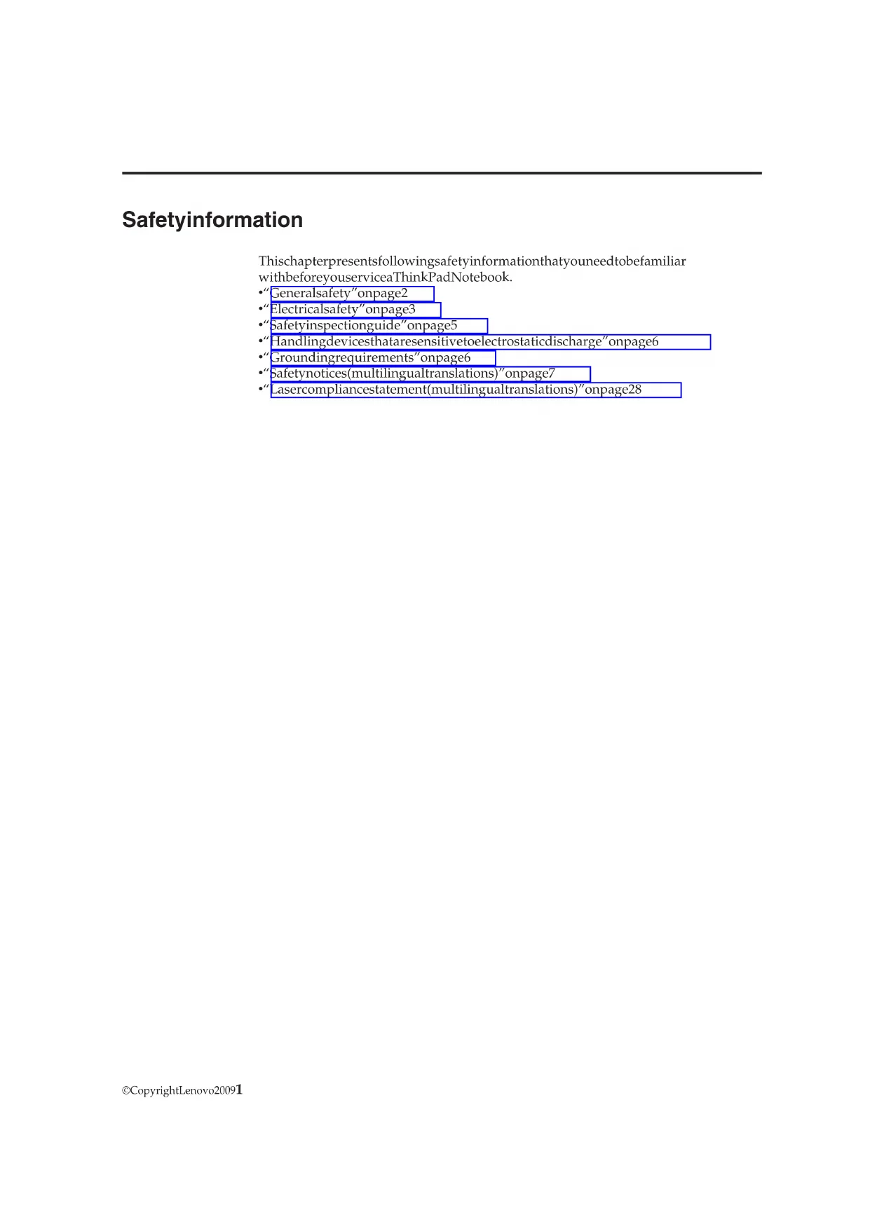
Contents
Aboutthismanual. v
Safetyinformation. 1
Generalsafety. 2
Electricalsafety. 3
Safetyinspectionguide. 5
Handlingdevicesthataresensitivetoelectrostatic
discharge. 6
Groundingrequirements. 6
Safetynotices(multilingualtranslations). 7
Lasercompliancestatement(multilingual translations). 28
Importantserviceinformation. 39
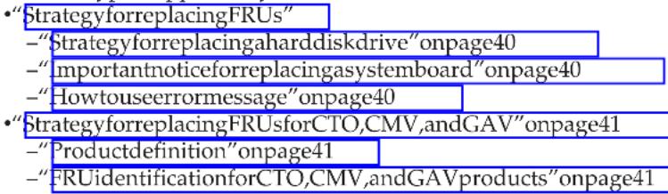
StrategyforreplacingFRUs. 39
Strategyforreplacingahardiskdrive. 40
Importantnoticeforreplacingasystemboard..40
Howtouseerrormessage. 40
StrategyforreplacingFRUsforCTO,CMV,and
G AV. 4
Productdefinition. 41
FRUidentificationforCTO,CMV,andGAV
products. 41
Generalcheckout 43
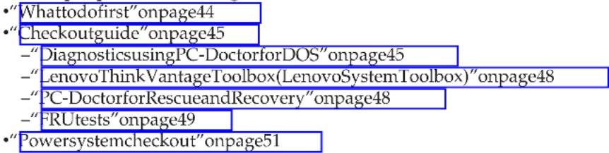
Whattodofirst. 4 4
Checkoutguide. 45
DiagnosticsusingPC-DoctorforDOS 45
LenovoThinkVantageToolbox(LenovoSystem
Toolbox). 4 8
PC-DoctorforRescueandRecovery. 48
FRUtests. 49
Powersystemcheckout. 51
Checkingtheacadapter 51
Checkingoperationalcharging. 52
Checkingthebatterypack 52
Checkingthebackupbattery 53
Relatedserviceinformation. 5 5
RestoringthefactorycontentsbyusingRecovery
DiscSet 5 5
Passwords. 56
Power-onpassword 57
Hard-diskpassword. 57
Supervisorpassword 57
Howtoremovethepower-onpassword. 57
Howtoremovethehard-diskpassword. 58
Powermanagement 60
Screenblankmode. 60
Sleep(standby)mode 60
Hibernationmode 61
Symptom-to-FRUindex 62
Numericerrorcodes. 62
Errormessage. 6 6
Beepsymptoms 67
No-beepsymptoms. 67
LCD-relatedsymptoms 68
Intermittentproblems. 69
Undeterminedproblems. 69
InstallingandconfiguringRAID. 71
SupportedRAIDconfigurations 71
ConfiguringthesystemBIOStoenableembedded
SATARAIIDfunctionality. 71
CreatingRAIDvolumes. 72
7 2
Statusindicators. 73
Fnkeycombinations 77
FRUreplacement notices. 81
Screwnotices. 81
Retainingserialnumbers. 82
Restoringtheserialnumberofthesystemunit 82
RetainingtheUUID 82
Reading or writing the ECA information 83
RemovingandreplacingaFRU. 85
BeforeservicingThinkPadT510,T510i,andW510 86
1010Batterypack. 87
1020SerialUltrabayEnhanceddeviceortravelbezel88
1030DIMMslotcover. 89
1040DIMM(bottomslot). 9 0
1050Harddiskdriveslotcover,harddiskdrive
(HDD)andHDDrubberrailorsSolidstatedrive
(SSD)andstorageconverter. 91
1060Keyboard 93
1070DIMM(upperslot) 97
1080 PCI Express Mini Card for wireless LAN. 98
1090 PCI Express Mini Card for wireless WAN . . 101
1100 Keyboard bezel assembly. 103
1110 Bluetooth daughter card (BDC-2.1) 106
1120 Backup battery 107
1130 SmartCard orContactlessSmartCardor
Smart Card dummy spacer. 108
1140 Speaker assembly 111
1150 Thermal module. 113
1160CPU. 116
1170 LCD unit 117
1180 Base cover assembly 121
1190 I/O sub card. 124
1200Systemboard assemblyandmagnesium
structure frame. 125
2010LCDbezelassembly 1 29
2020LEDsubcard 130
2030Integratedcamera 1 31
2040LCDcable,cameracable,LCDpanel,and hinges. 1 3 2050AntennakitandLCDrearcoverassembly135
1 3 7
Frontview. 1 3 7
Rearview. 1 3 9
Bottomview. 1 4
Partlist. 1 4 1
Overall. 1 4 2
LCDFRUs. 1 7 0
Keyboard. 1 8
Miscellaneousparts. 1 8 7
ACadapters. 1 8 9
2Powercords. 1 9 0
Recoverydiscs. 191
Windows XP Professional (32 bit) DVDs.. 192
Windows Vista Business (32 bit) DVDs.. 192
Windows7HomeBasic(32bit)DVDs. 193
Windows 7 Home Premium (32 bit) DVDs .. 194
Windows 7 Home Premium (64 bit) DVDs .. 195
Windows 7 Professional (32 bit) DVDs .. . 196
Windows 7 Professional (64 bit) DVDs .. 198
Commonservicetechnols. 200
Notices. 201 Trademarks. 202
Aboutthismanual
This manual contains service and reference information for the following ThinkPad products.
ThinkPadT510andT510i MT4313,4314,4339,4349,4384,4873,and4484
ThinkPadW510 MT4318,4319,4387,4389,4391,4875,and4876
Usethismanualalongwiththedefendeddiagnostisteststotroubleshooting problems.
Important:
This manualis intendedonly for trained servicetechnicians who are familiar with ThinkPad products. Use this manual along with the advanced diagnostic teststotroubleshooting, effectively.
BeforeservicingaThinkPadproduct,besuretoreadalltheinformationunder "Safetyinformation"onpage1and"Importantserviceinformation"onpage39.
Safetyinformation
This chapter presents followingsafety information that you need to be familiar with before you service a ThinkPad Notebook.
"Generalsafety"onpage2
Electricalsafety"onpage3
"Safetyinspectionguide"onpage5
"Handlingdevicessthataresensitivevetoelectrostaticdischarge"onpage6
"Groundingrequirements"onpage6
"Safety notices(multilingualtranslations)"onpage7
"“Lasercompliancestatement(multilingualtranslations)”onpage28
Generalsafety
Followtheserulestoensuregeneralsafety:
- Observe good housekeeping in the area of them machines during and after maintenance.
-
Whenliftinganyheavyobject:
-
Makesurethatyoucanstandsafterlywithoutslipping.
2.Distributetheweightoftheobjectequallybetweenyourfeet.
3.Useaslowliftingforce.Nevermovesuddenlyortwistwhenyouattemptto lift.
4.Liftbystandingorbypushingupwithyourlegmuscles;thisactionremoves thestrainfromthemusclesinyourback.Donotattempttoliftanyobjectthat weighmorethan16kg(35lb)orthatyouthinkistoohavyforyou.
- Donotperformanyactionthatcauseshazardstothecustomer,orthat makes the equipmentunsafe.
- Beforeyoustartthemachine, makesurethatotherservicetechniciansand the customer'spersonnelarenotinahazardousposition.
- Placeremovedcoversandotherpartsinasafeplace,awayfromallpersonnel, whileyouareservicingthemachine.
- Keep your toolcase away from walkareassothatotherpeople willnottripover it.
- Donot wear loose clothing that can be trapped in them moving parts of a machine. Makes sure that yoursleeves are fastened or rolled up above your elbows. If your hair is long, fasten it.
-Inserttheendsofyournecktieorscarfinsideclothingorfastenitwith anonconductiveclip,about8centimeters(3inches)fromtheend. - Donotwearjewelry,chains,metal-frameeyeglasses,ormetalfastenersforyour clothing.
Attention: Metalobjectsaregoodelectricalconductors.
Wearsafety glasses when you are hammering,drilling,soldering,cuttingwire, attaching springs,usingsolvents,orworkinganyotherconditionsthatmight behazardoustoyoureyes.
- Afterservice,reinstallallsafetyshields,guards,labels,andgroundwires. Replaceanysafetydevicethatiswornordefective.
-Reinstallallcoverscorrectlybeforereturningthemachinetothecustomer.
- Fanlouversonthemachinehelptopreventoverheatingofinternalcomponents. Donotobstructfanlouversorcoverthemwithlabelsorstickers.
Electricalsafety
Observethefollowingruleswhenworkingoneelectricalequipment.
Important:
Useonlyapprovedtoolsandtestequipment.Somehandtoolshavehandles coveredwithasoftmaterialthatdoesnotinsulateyouwhenworkingwithlive electricalcurrents.
Manycustomershave,neartheirequipment,rubberfloormatsthatcontainsmal conductivefiberstodecreaseelectrostaticdischarges.Donotusethistypeofmat toprotectyourselffromelecricalshock.
Findtheroomemergencypower-off(EPO)switch,disconnectingswitch,or electricaloutlet.Ifanelectricalaccidentoccurs,youcanthenoperatetheswitch orunplugthepowercordquickly.
- Donotworkaloneunderhazardousconditionsornequipmentthathas hazardousvoltages.
-Disconnectallpowerbefore:
-Performingamechanicalinspection
-Workingnearpowersupplies
-Removingorinstallingmainunits
-
Beforeyoustarttoworkonthemachine,unplugthepowercord.Ifyoucannot unplugit,askthecustomertopower-offthewallboxthsuppliespowertothe machine,andtolockthewallboxintheoffposition.
-
If you need to work on a machine that has exposed electrical circuits, observe the following precautions:
- Ensure that another person, familiar with the power-off controls, is nearby you.
Attention:Anotherpersonmustbetheretoswitchthepower,if necessary.
-Useonlyonehandwhenworkingwithpowered-oneelectricalequipment; keeptheotherhandinyourpocketorbehindyourback.
Attention: Anelectricalshockcanoccuronlywhenthereisacomplete circuit.Byobservingtheaboverule,youmaypreventacurrentfrompassing throughyourbody.
- When using testers, set the controls correctly and use the approved probe leads sand accessories forthattester.
- Standonsuitablerubbermats(obtainedlocally,ifnecessary)toinsulateyou fromgroundssuchasmetalfloorstripsandmachineframes.
Observethespecialsafetyprecautionswhenyouworkwithveryhighvoltages; Instructionsfortheseprecautionsareinthesafetysectionsofmaintenance information.Useextremecarewhenmeasuringhighvoltages.
Regularlyinspectandmaintainyourelectricalhandtoolsforsafeoperational condition.
- Donotusewornorbrokentoolsandtesters.
- Never assume that power has been disconnected from a circuit. First, check that it has been-poweredoff.
-
Alwayslookcarefullyforpossiblehazardsinyourworkarea.Examplesofthese hazardsaremoistfloors,nongroundedpowerextensioncables,powersurges, andmissingsafetygrounds.
-
Donottouchliveelectricalcircuitswiththereflectivesurfaceofaplasticdental mirror. Thesurfaceisconductive;suchtouchingcacausepersonalinjuryand machinedamage.
-
Do not service the following parts with the power on when they are removed from their normal operating places in an automatic machine:
-Powersupplyunits
-Pumps
-Blowersandfans
-Motorgenerators
-Similarunitstolistedabove
Thispracticeensurescorrectgroundingoftheunits.
-Ifanelectricalaccidentoccurs:
-Usecaution;donotbecomeavictimyourself.
-Switchoffpower.
-Sendanotherpersonontogetmedicalaid.
Safetyinspectionguide
The purpose of this inspectionguide eistoassistyouinidentifyingpotentially unsafeconditions. Aseachmachinewasdesignedandbuilt, requiredsafetyitems were installed to protect users and servicetechnicians from injury. This guide addresses only those items. You should use good judgment to identify potential safety hazards due to attachment of non-ThinkPad features or options not covered by this inspectionguide.
If any unsafe conditions are present, you must determine how serious the apparent hazard could be and whethery you can continue without first correcting the problem.
Consider these conditions and the safety hazards they present:
- Electricalhazards, especially primary power (primaryvoltageontheframecan causesseriousorfatalelectricalshock)
- Explosivehazards, such as damaged CRT faceorabulgingcapacitor
- Mechanical hazards, such as looseormissing hardware
Todeterminewhetherthereareanypotentiallyunsafeconditions,usethe followingchecklistatthebeginningofeveryservicetask.Beginthecheckswith thepoweroff,andthepowercord disconnected.
Checklist:
- Checkexteriorcoversfordamage(loose,broken,orsharpedges).
2.Poweroffthecomputer.Disconnectthepowercord. - Check the powercord for:
a. A third-wiregroundconnector good condition. Useametertomeasure third-wireground continuity for 0.1ohmorless between the external groundpin and theframeground.
b.Thepowercordshouldbethetypespecifiedinthepartlist. c.Insulationmustnotbefrayedorworn.
- Checkforcrackedorbulgingbatteries.
5.Removethecover. - Check for any obvious non-ThinkPad alterations. Use good judgment to the safety of any non-ThinkPad alterations.
- Checkinsidertheunitforanyobviousunsafeconditions,suchasmetalfilings, contamination,waterorotherliquids,orsignoffireormskedamage.
- Checkforworn,frayed,orpinchedcables.
- Check that the power-supplycoverfasteners (screwsorrivets) haven't been removedortampered with.
Handlingdevicesstataresensitivetoelectrostaticdischarge
Anycomputerpartcontainingtransistorsorintegratedcircuits(ICs)shouldbe consideredesensitivetoelectrostaticdischarge(ESD.)ESDdamagecanoccurwhen thereisadifferenceinchargebetweenobjects.ProctegagainstESDdamageby equalizingthechargesothatthemachine,thepart,theworkmat,andtheperson handlingthepartareallatthesamecharge.
Notes:
1.Useproduct-specificESDprocedureswhentheyexceedtherequirements notedhere.
- MakesurethattheESDprotectivedevicesyouusehavebeencertified(ISO 9000)asfullyeffective.
WhenhandlingESD-sensitiveparts:
- Keep the parts in protective packages until they are inserted into the product.
- Avoidcontactwithotherpeople.
Wearagroundedwriststrapagainstyourskintoeliminatestaticonyourbody. - Prevent the part from touching your clothing. Most clothing is insulative and retains scharge even when you are wearing a wrist strap.
- Useagroundedworkmattoprovideastatic-freeworksurface.Thematis especiallyusefulwhenhandlingESD-sensitivedevices.
- Selectagroundingsystem,suchasthoselistedbelow,toprovideprotectionthat meetsthespecificservicerequirement.
Note:
TheuseofagroundingsystemtoguardagainstESDdamageisdesirablebutnot necessary.
-AttachtheESDgroundcliptoanyframeground,groundbraid,orgreen-wire ground.
-Whenworkingonadouble-insulatedorbattery-operatedsystem,useanESD commongroundorreferencepoint.Youcanusecoaxorconnector-outside shellsonthesesystems.
-Usetheroundgroundprongoftheacplugonac-operatedcomputers.
Groundingrequirements
Electrical grounding of the computer is required for operators safety and correct system function. Proper grounding of the electrical outlet can be verified by a certified electrician.
Safetynotices(multilingualtranslations)
Thesafetynoticesinthissectionareprovidedinthefollowinglanguages:
English
Arabic
BrazilianPortuguese
French
German
- Hebrew
Japanese
Korean
Spanish
Traditional Chinese

DANGER
Before the computer is powered after FRU replacement, makes sure all screws, springs, and others small parts are in place and are not left loose inside the computer. Verify this by shaking the computer and listening for rattling sounds. Metallic parts or metal flakes can cause electrical shorts.

DANGER
Somestandbybatteriescontainasmallamountofnickelalandcadmium.Donot disassembleastandbybattery,rechargeit,throwitintofireorwater,orshort-circuitit. Disposeofthebatteryasrequiredbylocalordinancesorregulations.Useonlythethe batteryintheappropriatepartslisting.Useofanincorrectbatterycanresultinignition orexplosionofthebattery.

DANGER
Thebatterypackcontainssmallamountsofnickel.Donotdisassembleit,throwitinto fireorwater,orshort-circuitit.Disposethebatterypackasrequiredbylocal ordinancesorregulations.Useonlythebatteryintheappropriatepartslistingwhen replacingthebatterypack.Useofanincorrectbatterycanresultinignitionorexplosion ofthebattery.

DANGER
Thelithiumbatterycancauseafire,anexplosion,orasevereburn.Donotrechargeit, removeitspolarizedconnector,disassembleit,heatitatabove 100^(212^) ,incinerateit, orexposeitscellcontentstowater.Disposefthebatteryasrequiredbylocal ordinancesorregulations.Useonlythebatteryintheappropriatepartlisting.Useofan incorrectbatterycanresultinignitionorexplosionofthebattery.

DANGER
IftheLCDbreaksandthefluidfrominsidetheLCDgetsintoyoureyesoronyour hands,immediatelywashtheaffectedareaswithwaterforatleast15minutes.See medicalcareifanysymptomsfromthefluidarepresentafterwashing.

DANGER
Toavoidshock,donotremovetheplasticcoverthatprotectsthelowerpartofthe invertercard.

DANGER
Thoughtthemainbatterieshavelowvoltage,ashortedorgrounddbatterycan produce enoughcurrenttoburnpersonnelorcombustiblematerials.

DANGER
UnlesshotswapisallowedfortheFRUbeingreplaced,doasfollowsbeforeremoving it:poweroffthecomputer,unplugallpowercordsfromelectricaloutlets,removethe batterypack,anddisconnectanyinterconnectingcables.
FRIU 1y JyI yuall yuall yuall yuall yuall yuall yuall yuall yuall yuall yuall yuall yuall yuall yuall yuall yuall yuall yuall yuall yuall yuall yuall yuall yuall yuall yuall yuall yuall yuall yuall yuall yuall yuall
yall Jaiu 1alal alal jai
F F F F F F F F F F F F F F F F F F F F F F F F F F F F F F F F F F F F F F F F F F F F F F F F F F F F F F F F F F F F F F F F F F F F F F F F F F F F F F F F F F F F F F F F F F F F F F F F F F F F F
Aaiin ciXs gJ Laiy jy Jyj 1

PERIGO
AntesdeligarocomputadoraposasubstituacaoFRU,certificque-sedequetodosos parafusos,molaseoutraspeçaspequenasestejamnolugarenaoestjeamsoltosdento docomputador.Verifiqueissosacudindoocomputadoreprocurandoouvirnsde peassoltas.Pecasmetálicasoulascasdemetalpodemcausarcurto-circuito.

PERIGO
CAUTION: Useofcontrolsoradjustmentsorperformanceofproceduresotherthan those specifiedhereinmightresultinhazardousradiationexposure.
OpeningtheCD-ROMdrive, the DVD-ROMdrive, or any other optical storage device could result in exposure to hazardous lasers radiation. There are no serviceable parts in the dosed drives. Donotopen.
ACD-ROMdrive,aDVD-ROMdrive,oranyotherstoragedeviceinstalledmay containanembeddedClass3AorClass3Blaserdiode.Notethefollowing:

DANGER
Emitsvisibleandinvisiblelaserradiationwhenopen.Donotstareintothe beam,donotviewdirectlywithopticalinstruments,andavoiddirectexposure tothebeam.
This chapter presents following important service information that appliestoall machinetypepsupportedbythismanual:
Important:
BIOSanddevicedriverfixesarecustomer-installable.TheBIOSanddevice driversarepostedonthecustomersupportsiterehttp://www.lenovo.com/support
SystemDisassembly/ReassemblyvideoosthatshowtheFRUremovalsor replacementsfortheLenovo ^ 念 authorizedservicetechniciansareavailableinthefollowingsupportsite:htp://www.lenovoservicetraining.com/ion/
AdvisecustomerstocontacttheCustomerSupportCenterat800-426-7378ifthey needassistanceinobtainingorinstallinganysoftwarefixes,drivers,andBIOS downloads.
CustomersinCanadashouldcalltheCustomerSupportCenterat800-565-3344 forassistanceordownloadinformation.
StrategyforreplacingFRUs
Beforereplacingparts:
Makesurethatallassoftwarefixes,drivers,andBIOSdownsareinstalled before replacing any FRU listed in this manual.
Afterasystemboarddisplaced,ensurethatthelatestBIOSisloadedtothesystemboardbeforecompletingtheserviceaction.
Todownloadsoftwarefixes,drivers,andBIOS,doasfollows:
1.Gotohttp://www.lenovo.com/support
2. Enter the product number of the computer or press Auto-detect button on the screen.
3. Select Downloadsanddrivers.
4. Followthedirectionsonthescreenandinstallthenecessaryysoftware.
Use the following strategy to prevent unnecessary expense for replacing and servicing FRUs:
- IfyouareinstructedtoreplaceaFRUbutthereplacementdoesnotcorrectthe problem,reinstalltheoriginalFRUbeforeyoucontinue.
- Somecomputershaveboththaprocessorboardandasystemboard.Ifyou are instructedtoreplaceeithertheprocessorboardorthesystemboard,and replacingoneofthemdoesnnotcorrecttheproblem,reinstallthatboard,and thenreplacetheotherone.
- IfanadapteroradeviceconsistsofmorethanoneFRU,anyoftheFRUsmay bethecauseoftheerror.Beforereplacingheadapterordevice,removethe FRUs,onebyone,toseeifthesymptomschange.ReplaceonlytheFRUthat changedthesymptoms.
Attention: Thesetupconfigurationonthecomputeryouareservicingmayhave beencustomized. Running Automatic Configuration may alter the settings. Note the current configurationsettings(using the View Configuration option); then, whenever has been completed, verify that thosesettings remain in effect.
Strategyforreplacingahardiskdrive
Alwaystrytorunalow-levelformatbeforereplacingaharddiskdrive.Thiswill causeallcustomerdataontheharddisktobelost.Besurethatthecustomerhasacurrentbackupofthedatabeforedoingthistask.
Attention: The drivestartupsequence in the computery youareservicing may have been changed. Beextremelycarefulduringwriteoperationssuchascopying, saving, or formatting. If youselectanincorrectdrive, dataorprogramscanbe overwritten.
Importantnoticeforreplacingasystemboard
Somecomponentsmountedonasystemboarddareverysensitive.Improper handlingofasystemboardcauseddamagetothosecomponents,andmay causeasysteemmalfunction.
Attention:Whenhandlingasystemboard:
- Donotdropystemboardorapplyanyexcessiveforcetoit.
- Avoidroughhandlingofanykind.
- Avoid bending asystemboard and hard pushing to prevent cracking at each BGA (BallGrid Array) chipset.
Howtouseerrormessage
Usetheerrorcodesdisplayedonthescreentodiagnosefailures.Ifmorethanone errorcodeisdisplayed,beginthediagnosiswiththefirstterrorcode.Whatever causes the first terrorcodemayalsousefalseerrorcodes.Ifnoerrorcode is displayed,seewhatthereerrorsymptomislistedintheSymptom-to-FRUInd for the computer youareservicing.
StrategyforreplacingFRUsforCTO,CMV,andGAV
Productdefinition
DynamicConfigureToOrder(CTO)
This providestheabilityforacustomertoconfigureanIBM ^© oraLenovosolution fromaneSite,andhavethisconfigurationsenttofulfillment,whereitisbuilt and shippeddirectlytothecustomer.Themachinelabel,ProductEntitlement Warehouse(PEW),eSupport,andtheHMMwillloadtheseproductsaste4-digit MTand3-digitmodel,wheremodel="CTO"(Example:1829-CTO).
CustomModelVariant(CMV)
ThisisauniqueconfigurationthathasbeennegotiatedbetweenIBMorLenovo andthecustomer.Aunique4-digitMTand3-digitmodelisprovidedtothe customertplaceorders(Example:1829-W15).ACMVisaspecialbid offering. Therefore,itisNOTgenerallyannounced.
TheMTMportionofthemachinelabelisthe4-digitMTand3-digitmodel, where model = "CTO"(Example:1829-CTO).ThePRODUCTIDportionofthe machinelabelisthe4-digitMTand3-digitCMVmodel(Example:1829-W15).
The PEWrecordisthe4-digitMTand3-digitmodel,where model = "CTO" (Example:1829-CTO).
-eSupportwillshowboththeCTOandCMVmachinetype models(Example: 1829-CTOand1829-W15willbefoundontheeSupportsite.)
TheHMMwillhavethe4-digitMTand3-digitCTOmodelonly(Example: 1829-CTO).Again,CMVsarecustommodelsandarenotfoundintheHMM.
GeneralAnnounceVariant(GAV)
Thisisastandardmodel(fixedconfiguration).GAVsareannouncedandofferedto allcustomers.TheMTMportionofthemachinelabelisa4-digitMTand3-digit model,wheremodel=a"fixedpartnumber",not"CTO"(Example:1829-F1U). Also,PEW,eSupport,andtheHMMwilllisttheseproductsunderthesamefixed modelnumber.
FRUidentificationforCTO,CMV,andGAVproducts
TherearethreeinformationresourcestoidentifywhichFRUsareusedtosupport CTO,CMV,andGAVproducts.ThesesourcesarePEW,eSupport,andtheHMM.
UsingPEW
- PEWistheprimarysourceforidentifyingFRUpartnumbersandFRU descriptionsforthekeycommoditiesforCTO,CMVandGAVproductsataMT -serialnumberlevel.Anexampleofkeycommoditiesareharddiskdrives, systemboards,microprocessors,LiquidCrystalDisplays(LCDs),andmemory.
- Remember, all CTO and CMV products are loaded in PEW under the 4-digit MT and 3-digit model, where model = "CTO"(Example:1829-CTO). GAVs are loaded in PEW under the 4-digit MT and 3-digit model, where model = a "fixed part number", not "CTO"(Example:1829-F1U).
-
PEWcanbeaccessedatthefollowingWebsite: http://www.lenovo.com/support/site.wss/document.do?Indocid=LOOK-WARNING SelectWarrantylookup.InputtheMTandtheSerialnumberandthelistofkey commoditieswillbereturnedinthePEWrecordunderCOMPONENT INFORMATION.
-
Business Partners using Eclaim will access PEW when performing Entitlement Lookup.BusinessPartnerswillenterLocID,MTandSerial,andthekey commoditieswillbereturnedintheEclaimrecordunderSYSTEMDETAILS.
- AuthorizedIBMBusinessPartnerscanaccessEclaimatthefollowingWebsite: https://wca.eclaim.com
UsageSupport
ForKeyCommodities(Examples-harddiskdrive,systemboard, microprocessor,LCD,andmemory)
-eSupportcanbeusedtoviewthelistofkeycommoditiesbuiltinaparticlarmachineserial(thisisthesamerecordfoundinPEW).
- eSupport can be accessed at the following Web site: http://www.lenovo.com/support
Toviewthekeycommodities,clickonPARTSINFORMATION,thenPARTS LOOKUP.Typeinthemodeltypepeandserialnumber.Thekeycommoditieswill bereturnedintheeSupportrecordunderPARTSSHIPPEDWITHYOUR SYSTEM.
FortheRemainingFRUs(thecompletelistofFRUsattheMTModellevel)
-eSupportcanbeusedtoviewthecompletelistofFRUsforamachinetypeand model.
ToviewthecompletelistofFRUs,typeinthemachinetypeandmodel (Example:1829-CTO)underQUICKPATH.Under"ViewbyDocumentType" selectPARTSINFORMATION.Under"FilterbyCategory"selectSERVICE PARTS.Under"PartsInformationbyDate"selectSYSTEMSERVICEPARTS.The listofservicepartsbydescription,withapplicablemachinetype modelandFRU willbedisplayed.
UsingtheHMM
ForKeyCommodities(Examples-harddiskdrive,systemboard, microprocessor,LCD,andmemory)
UsetheHMMasaback-uptoPEWandeSupporttoviewthecompletelistof FRUsattheMTModellevel.
Generalcheckout
This chapter presents following information:
The descriptions in this chapter apply to any ThinkPad model that supports the PC-Doctor for DOS diagnostics program. Some descriptions might not apply to your particular computer.
Beforeyougotothecheckoutguide,besuretoreadthefollowingimportantnotes.
Importantnotes:
-Onlycertifiedtrainedpersonnelshouldservicethecomputer.
- BeforereplacinganyFRU,readtheentirepageonremovingandreplacing FRUs.
- When you replace FRUs, use newnylon-coated screws.
- Beextremelycarefulduringsuchwriteoperationsascopying,saving,or formatting.Drivesinthecomputerthatyouareservicingssequencemight havebeenaltered.Ifyouselectanincorrectdrive,dataorprogramsmightbe overwritten.
- ReplaceaFRUonlywithanotherFRUofthecorrectmodel.Whenyou replaceaFRU,makesurethatthemodelofthemachineandtheFRUpart numberarecorrectbyreferringtotheFRUpartlist.
- AFRUshouldnotbereplacedbecauseofasing,unreproduciblefailure. Singlefailurescanoccurforavarietyofreasonsthavenothingtodowith ahardwaredefect,suchascosmicradiation,electrostaticdischarge,or softwareerrors.ConsiderreplacingaFRUonlywhenaproblemrecurs.Ifyou suspectthataFRUsdefective,cleartheerrorlogandrunthetestagain.If theerrordoesnotrecur,donotreplacetheFRU.
-BecarefulnottoreplaceanondefectiveFRU.
Whattodofirst
WhenyoudoreturnaFRU,youmustincludethefollowinginformationinthe partexchangeformorpartsreturnformthatyouattachtoit:
1.Nameandphonenumberofservicetechnician
2. Dateofservice
3. Dateonwhichthemachinefailed
4. Dateof purchase
5. Failuresymptoms, errorcodesappearingonthedisplay, andbeep symptoms
6.ProcedureindexandpagenumberinwhichthefailingFRUwasdetected
7.FailingFRUnameandpartnumber
8.Machinetype,modelnumber,andserialnumber
9. Customer'snameandaddress
Noteforwarranty:Duringthewarrantyperiod,thecustomermayberesponsible forrepaircostsifthecomputerdamagewascausedbymisuse,accident, modification,unsuitablephysicaloroperatingenvironment,orimproper maintenancebythecustomer.
Followingisalistofsomecommonitemsthatarenotcoveredunderwarranty and somesymptomsthatmightindicatethatthesystemwassubjectedtostressbeyond normaluse.
Beforecheckingproblemswiththecomputer,determinewhetherthedamageiscoveredunderthewararrantybyreferringtothefollowinglist:
The followingarenotcoveredunderwarranty:
- LCDpanelcrackedfromtheapplicationofexcessiveforceorfrombeing dropped
- Scratched(cosmetic)parts
Distortion, deformation, ordiscoloration of thecosmeticparts - Plasticparts, latches, pins, or connectorsthathavebeencrackedorbrokenby excessiveforce
- Damagecausedbyliquidspilledintothesystem
- DamagecausedbytheimproperinsertionofaPCCardorthearinstallationofan incompatiblecard
- Improperdiscinsertionoruseofanopticaldrive
- Diskettedrivedamagecausedbypressureonthediskettedrivecover,foreign materialinthedrive,ortheinsertionofadiskettewithmultiplelabels
- Damagedorbentdisketteejectbutton
-Fusesblownbyattachmentofanonsupporteddevice - Forgottencomputerpassword(makingthecomputerunusable)
- Stickykeyscausedbyspillingaliquidontothekeyboard
-Useofanincorrectacadapteronlaptopproducts
The followingsymptomsmightindicatedamagecausedbynonwarranted activities:
- Missingpartsmightbeasymptomofunauthorizedserviceormodification.
- Ifthespindleofahardiskdrivebecomesnoisy, it may have been subjected to excessive force,ordropped.
Checkoutguide
Use the following procedures as guidecinidentifying and correcting problems with the ThinkPad Notebook.
Note:ThediagnostictestsareintendedtotestonlyThinkPadproducts.Theuseof non-ThinkPadproducts,prototypecards,ormodifiedoptionscanleadtofalse indicationsoferrorsandinvalidsystemresponses.
1.Identifythefailingsymptomsinasmuchdetailaspossible.
2.Verifythesymptoms.Trytore-createthefailurebyrunningthediagnostictest orbyrepeatingtheoperation.
DiagnosticsusingPC-DoctorforDOS
TheThinkPad NotebookhasatestprogramcalledPC-DoctorforDOS(hereafter calledPC-Doctor.)Youcantecterrorsbyrunningthediagnosticstestincluded in PC-Doctor.
Note:
PC-DoctorforDOSisavailableatthefollowingWebsite:http://
www.lenovo.com/support
TocreatethePC-DoctordiagnosticCD, follow the instructionsontheWebsite.
Forsomepossibleconfigurationsofthecomputer,PC-Doctormightnotrun correctly.Toavoidthisproblem,youneedtoinitializethecomputersetupbyuse oftheBIOSSetupUtilitybeforeyourunPC-Doctor.
ToenterBIOSSetupUtility,doasfollows:
- Turnonthecomputer.
- WhentheThinkPadlogocomesup, immediatelypressF1toentertheBIOS SetupUtility.
Note:Ifasupervisorpasswordhasbeensetbythecustomer,BIOSSetupUtility menuappearsafterthepassworddisentered.Youcanstarttheutilitybypressing Enterinsteadofenteringthesupervisorpassword;however,youcannotchangethe parametersthatareprotectedbythesupervisorpassword.
OntheBIOSSetupUtilityscreen,pressF9,Enter,F10,andthenEnter.
Note:Whenyouinitializethecomputerconfiguration,somedevicesaredisabled, suchastheserialport.Ifyoutestoneofthesedevices,youwillneedtoenableit byusingConfigurationutilityforDOS.Theutilityisavailableonthefollowing Website:http://www.lenovo.com/support
PC-Doctorcannotbeusedtotestadevicethatisinthedockingstation,evenifthe computersupportsthedockingstation.TotestaUSBdevice,connectittotheUSB connectorofthecomputer.
Testingthecomputer
Note:ThePC-DoctordiagnosticCDdoesnotsupportanyopticaldrivesconnected throughUSBdevicesoranyothers.Itsupportsonlytheinternalopticaldriveof theThinkPad Notebook.
Torunthe test,doasfollows:
- Turnoff the computer.
- Makesurethattheinternalopticaldrivethatissupportedasastartupdevice isattachedtothecomputer.
- Turnonthecomputer.
If the computer cannot be powered on, goto "PowerSystemcheckout" on page51 and check the power sources.
Ifanerrorcodeappears,goto"Synlptom-to-FRUindex"onpage62.
- WhentheThinkPadlogocomesup,immediatelypressF12toentertheBoot Menu.
- InsertthePC-DoctorCDintotheinternalopticaldrive.
- Press cursor keys to select ATAPI CDx (x: 0, 1, ...) and then press Enter.
- Followtheinstructionsonthescreen.
- ThemainpanelofPC-Doctorappears.
- SelectDiagnosticswiththearrows,andpressEnter.
Note:You can select itemnotonly with the arrow keys, but also with the TrackPoint pointer. Instead of pressing Enter, click the left button.
Apull-downmenuappears. (It's exact form depend on themodel.)
Note:PC-Doctormenudoesnnotmeantheformalsupportdevicelist.Some unsupporteddevicenamesmayappearinthePC-Doctormenu.
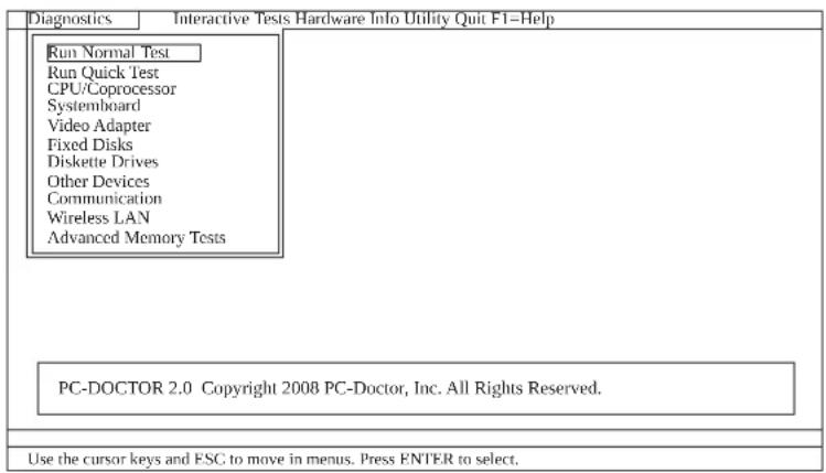
Theoptionsonthetestmenuareasfollows:
| DiagnosticsInteractiveTests | |
| •RunNormalTest •RunQuickTest •CPU/Coprocessor •Systemboard •VideoAdapter •FixedDisks •DisketteDrives •OtherDevices •ThinkPadDevices •Communication •WirelessLAN •AdvancedMemoryTests | •Keyboard •Video •InternalSpeaker •Mouse •Diskette •SystemLoad •OpticalDriveTest •IntelWLANRadioTest |
| Note: • In the Keyboard test in Interactive Tests, the Fn key should be held down for at least 2 seconds; otherwise, it cannot be sensed. • Video Adapter test supports only the LCD display on the ThinkPad Notebook. If you have an external monitor attached to your computer, detach it before running PC-DoctorforDOS. • To test Digital Signature Chip, the security chip must be set to Active. | |
- Runtheapplicablefunctiontest.
11.Followtheinstructionsonthescreen.Ifthereisaproblem,PC-Doctorshowss messagesdescribingit.
12.Toexitthetest,selectQuit—ExitDiag. Tocancelthetest,pressEsc.
Note:Afterr runningPC-Doctor,checkthe timeand date on the systemmandreset themiftheyareincorrect.
DetectingsysteminformationwithPC-Doctor
PC-Doctorcandetectthefollowingsysteminformation:
HardwareInfo
*SystemConfiguration
MemoryContents
PhysicalDiskDrives
LogicalDiskDrives
VGAInformation
-IDEDriveInfo
-PCIIInformation
-PNPISAInfo
SMBIOSInfo
VESALCDInfo
- HardwareEventsLog
Utility
-RunExternalTests
SurfaceScanHardDisk
BenchmarkSystem
-DOSShell
TechSupportForm
BatteryRundown
-ViewTestLog
-PrintLog
SaveLog
FullEraseHardDrive
-QuickEraseHardDrive
LenovoThinkVantageToolbox(LenovoSystemToolbox)
LenovoThinkVantage® Toolbox(LenovoSystemToolboxinWindowsVista® and Windows® XP)isadiagnosticprogramthatworksthroughtheWindowsoperating system.Itenablesyoutoviewsymptomsofcomputerproblemsandsolutionsfor them,andincludesautomaticnotificationwhenactionisrequired,computing assistance,advanceddiagnostics,anddiagnostichistory.
Note:
ThelatestLenovoThinkVantageToolbox(LenovoSystemToolbox)isavailableat thefollowingWebsite:htp://www.lenovo.com/support
ToinstallthelatestLenovoThinkVantageToolbox(LenovoSystemToolbox)on thecomputer, followtheinstructionsontheWebsite.
Torunthisprogram,doasfollows:
Windows7:
While the Windowsoperatingsystemisrunning, pressthe ThinkVantagebutton.
You canalsorunthisprogramaseitherofthe following:
- Click Start -> All Programs -> Lenovo ThinkVantage Tools -> System Health and Diagnostics.
- Click Start -> Control Panel -> System and Security -> Lenovo's System HealthandDiagnostics.
WindowsVistaandWindowsXP:
Click Start --> All Programs --> Lenovo Services --> Lenovo System Toolbox.
Followtheinstructionsonthescreen. LenovoThinkVantageToolbox(Lenovo SystemToolbox)alsohasproblemdeterminationaidsthatdetermininesoftwareand usageproblems.
Foradditionalinformationaboutthisprogram,seetheHelpfortheprogram.
PC-DoctorforRescueandRecovery
InsomemodelsofThinkPadNotebook, the Rescue and Recovery workspace enables you to run the PC-Doctorprogramtotestthehardwarefeatures of the computer.
Torunthe test, click "Run Diagnostics" on the Rescue and Recovery mainscreen.
FRUtests
ThefollowingtableshowsthetestforeachFRU.
Table1.FRUtests
| FRUApplicabletest | |
| System board | 1. Diagnostics -> CPU/Coprocessor2. Diagnostics->>Systemboard3. Ifthedockingstationortheportreplicatorisattached totheThinkPad Notebook,detachit.4. Placethecomputerahorizontalsurface,andrun Diagnostics->>ThinkPad Devices->>HDDActive ProtectionTest.Note: Donotapplyanyphysicalshocktothecomputer whilethetestisrunning. |
| Power | Diagnostics -> ThinkPad Devices -> AC Adapter, Battery 1(Battery2) |
| LCDunit1.Diagnostics | ->VideoAdapter2. InteractiveTests->>Video |
| AudioEntertheBIOSSet | setupUtilityandchangeSerialATA(SATA) setting to Compatibility, and run Diagnostics -> Other Device->>ConexantAudio |
| SpeakerInteractiveTests | InternalSpeakerNote:OnceAudiostestisdone,thenosoundisheardthis test.Inthiscase,turnoffandturnonthecomputer.Then, runthistestagain. |
| Keyboard | 1. Diagnostics -> Systemboard -> Keyboard2. InteractiveTests->>Keyboard |
| Hardiskdriveor solidstatedrive | EntertheBIOSSetupUtilityandchangeSerialATA(SATA) setting to Compatibility, and run Diagnostics -> Fixed Disks |
| Youcanalsodiagnosedrivewithoutstartingupthe operationsystem.TodiagnosedrivefromtheBIOS SetupUtility,doasfollows:1. Removeany diskettefromthediskettedrive,andthen turnoffthecomputer.2. Turnonthecomputer.3. Whilethemessage, "Totimeruptnormalstartup,press theblueThinkVangatebutton," is displayedatthelower leftofthescreen,pressF1toentertheBIOSSetup Utility.4.Usingcursorkeys,selectHDDdiagnosticprogram.Pressenter.5.Usingcursorkeys,selectMainharddiskdriveor Ultrabayhardiskdrive.6. PressEntertostartthediacnesticprogram. | |
| Diskette drive | 1. Diagnostics -> Diskette Drives2. InteractiveTests->>Diskette |
| Optical drive | 1. Diagnostics -> Other Devices->> Optical Drive2. InteractiveTests->>OpticalDriveTest |
| Memory1.IftwoDIMM | sareinstalled,removeofthemand run Diagnostics -> Advanced Memory Tests.2.Iftheproblemdoesnotrecur,returntheDIMMtoits place,removetheotherone,andrunthetestagain. |
| TrackPointor pointingdevice | IftheTrackPointdoesnetwork,checktheconfigurationas specifiedintheBIOSSetupUtility.IftheTrackPointis disabled,selectAutomaticitenableit.AfteryouusetheTrackPoint,thepointermaydriftonthe screenforashorttime.Thisdriftcanoccurwhenaslight, steadypressureisappliedtotheTrackPointpointer.This symptomisnotahardwareproblem.Ifthepointerstops afterashorttime,noserviceactionisnecessary.IfenablingtheTrackPointdoesnotcorrecttheproblem, continuewiththefollowing: •InteractiveTests->Mouse |
| TouchPadIftheTouchP | addoesnetwork,checktheconfigurationas specifiedintheBIOSSetupUtility.IftheTouchPadis disabled,selectAutomaticitenableit.Ifenablingthe TouchPaddoesn'tcorrecttheproblem,continuewiththe following: •InteractiveTests->Mouse |
Powersystemcheckout
Toverifyasymptom,dothefollowing:
- Turnoff the computer.
2.Removethebatterypack. - Connect theacadapter.
- Checkthatpowerissuppliedwhenyouturnnonthecomputer.
5.Turnoffthecomputer.
6.Disconnecttheacadapterandinstallthechargedbatterypack. - Check that the batterypacks supplies power when you turn on the computer.
If you suspect tapowerproblem,seetheappropriateoneofthefollowingpower supplycheckouts:
"Checkingtheacadapter"
"Checkingoperationalcharging" onpage52
"Checking the battery pack" onpage52
"Checkingthebackupbattery"onpage53
Checkingtheacadapter
You are here because the computer fails only when the acadapter is used.
-If the power problem occurs only when the docking station or the portreplicator is used, replaced the docking station or the portreplicator.
- Ifthepower-onindicatordoesnotturnnon,checkthepowercordoftheac adapterforcorrectcontinuityandinstallation.
-If the computer does not charge during operation, goto "Checking operational charging" on page 52.
Tochecktheacadapter,dothefollowing:
- Unplugtheacadaptercablefromthecomputer.
2.Measuretheoutputvoltageattheplugoftheacadaptercable.Seethe followingfigure:
(20V)
| PinVoltage(Vdc) | |
| 1+20 | |
| 2 | 0 |
| 3Ground | |
Note:Outputvoltageofpinno.2oftheacadaptermaydifferenftfromtheone youareservicing.
3.Ifthevoltageisnotcorrect,replacetheacadapter.
4.Ifthevoltageisacceptable,dothefollowing: -Replacethesystemboard.
-Iftheproblempersists,goto"FRU-tests"onpage49.
Note: Noisefromtheadapterdoesnnotalwaysindicatedefect.
Checkingoperationalcharging
Tocheckwhetherthebatterychargesproperlyduringoperation,useadischarged batterypackorabatterypackthathaslessthan50%ofthotalpowerremaining wheninstalledinthecomputer.
Perform operational charging. If the battery status indicator oricon does not turn on, remove the battery pack and let it return to room temperature. Reinstall the battery pack. If the charge indicator is still does not turn on, replace the battery pack.
Ifthechargeindicatorstilldoesnnotturnnon,replacethesystemboard.Then reinstallthebatterypack.Ifitisstillnotcharged,gotothenextsection.
Checkingthebatterypack
Batterychargingdoesn'tstartuntilthePowerManagerBatteryGaugeshowsthat lessthan 96% of the total power remains; under this condition the battery pack can charge to 100% of its capacity. This protects the battery pack from being overcharged from having as shortened life.
Tocheckourbattery,moveourcursortothePowerManagerBatteryGaugeicon intheicontrayoftheWindowstaskbarandwaitforamoment(butdonotclick), andthepercentageofbatterypowerremainingisdisplayed.Togetdetailed informationaboutthebattery,double-clickthePowerManagerBatteryGaugeicon.
Note:Ifthebatterypackbecomeshot,itmaynotbeabletocharge.Removeit from the computer and leave it at room temperature for awhile. After it cools down, reinstall and recharge it.
Tocheckthebatterypack,dothefollowing:
1.Poweroffthecomputer.
- Removethebatterypackandmeasurethevoltagebetweenbatteryterminals1 (+)and7(-).Seethefollowingfigure:
| TerminalVoltage(Vdc) | |
| 1+0to+12.6 | |
| 7Ground(-) | |
3.Ifthevoltageislessthan+11.0Vdc,thebatterypackhasbeendischarged.
Note:Rechargingwilltakeatleast3hours,eveniftheindicatordoesnotturn on.
Ifthevoltageisstilllessthan+11.0Vdcafterrecharging,replacesbattery.
4.Ifthevoltageismorethan+11.0Vdc,measuretheresistancebetweenbattery terminals5and7.Theresistancemustbe4to30KΩ.
Iftheresistanceisnotcorrect,replacethebatterypack.Iftheresistanceiscorrect,replacesystemboard.
Checkingthebackupbattery
Dothefollowing:
1.Poweroffthecomputer,andunplugtheacadapterfromit.
2.Turnthecomputerupsidedown.
3. Removethebatterypack(see "101(Batterypack" onpage87).
4. Removethebackupbattery(see "112"Backupbattery"onpage107).
5.Measurethevoltageofthebackupbattery.Seethefollowingfigure.
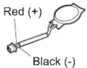
| WireVoltage(Vdc) |
| Red+2.5to+3.2 |
| BlackGround |
Ifthevoltageiscorrect,replacethesystemboard.
-Ifthevoltageisnotcorrect,replacethepacketupbattery.
- If the backup battery discharges quickly after replacement, replace the system board.
Relatedserviceinformation
This chapter presents following information:
RestoringthefactorycontentsbyusingRecoveryDiscSet
"Passwords"onpage56
"Powermanagement"onpage60
"Symptom-to-FRUindex"onpage62
ServiceWebsite:
Whenthelatestmaintenancedisketteandthesystemprogramservicediskette becomeavailable,theywillbepostedonhttp://www.lenovo.com/spm
RestoringthefactorycontentsbyusingRecoveryDiscSet
Whentheharddiskdrive(HDD)orsolidstatedrive(SSD)isreplacedbecauseofa
failure,noproductrecoveryprogramisonthenewdrive.Inthiscase,youm
usetheRecoveryDiscSetforthecomputer.OrdertheRecoveryDiscSetandthe
driveatthesametimesothatyoucanrecoverthenewdrivewiththepre-installed
softwarewhentheyarrive.Forinformationonwhichdiscstoorder,see"Recovery
discs"onpage191.
Therecoverydiscsetconsistsoftheuserinstructionsandthefollowingsetof
DVDstorestorethecomputertotheoriginalfactoryconfiguration.
OperatingSystemRecoveryDisc(onedisc)
This discrestoresthe Microsoft
Windowsoperatingsystem.Usethisdisc
tostarttherecoveryprocess.
ApplicationsandDriversRecoveryDisc(oneormorediscs)
This discrestoresthepreinstalledapplicationsanddriversonthe
computer.
SupplementalRecoveryDisc
This discontains additional content, such as updates to the software that
waspreinstalledonthecomputer.Notallrecoverydiscsetscomewitha
SupplementalRecoveryDisc.
Notes:
- You must have a DVD drivetrain recovery discs. If you don't have an internal DVD drive, you can use an external USB DVD drive.
- Duringtherecoveryprocess, alldataonthedrivewillbedeleted. Ifpossible, copyanyimportantdataorpersonalfilesthatyouwanttokeepontremovable mediaoranetworkdrivebeforeyoustarttherecoveryprocess.
Torestorethecomputertotheoriginalfactoryconfigurationusingtherecovery
discset,dothefollowing:
Note:Recoverytakeseveralhours. Thelengthoftimedependsonthemethod youuse.Ifyouuserecoverydiscs,recoverytakesatleastfivehours.
- Make the CD/DVD drivethefirststartupdevice inthestartupsequence using the following procedure:
a. PressandholddowntheF1key, and thenturnonthecomputer. Whenthe logoscreenisdisplayedorifyouhearrepeatingbeeps, release the F1key. TheSetup Utility program opens.
b. Use the arrow keys to select Startup Boot.
c.SelecttheCD/DVDdriveasthe1stBootDevice.
2.InserttheOperatingSystemRecoveryDiscintotheDVDdrive.
-
PressF10tosavetheSetupUtilityconfigurationchanges. Follow the instructionsonthescreentobegintherecoveryprocess.
-
Select your language and click Next.
-
Read the license. If you agree with the terms and conditions, select I accept these terms and conditions and then click Next. If you do not agree with the termsandconditions, followtheinstructionsonthescreen.
- Click Yes in the displayed window to begin the operating system recovery process.
- Insert the Applications and Drivers Recovery Disc when prompted and then click OKtobegintheapplicationsanddriversrecoveryprocess.
- If you have a Supplemental Recovery Disc, insert it when prompted and click Yes. If you do not have a Supplemental Recovery Disc, click No.
- When allofthedata has been copied from the last discintheset and has been processed, removed the computer.
Note:Therestoftherecoveryprocessisfullyautomatedandnoactionis requiredbyyou. ThecomputerwillrestartintotheMicrosoftWindows desktopseveraltimesandyoumightexperienceperiodswhennoactivityis apparentonthescreenforseveralminutesatatime.Thisisnormal.
- Whentherecoveryprocessiscomplete, the Set Up Windows screenshot is displayed. Follow the instruction on the screent to complete the Windows setup.
- After you have completed the Windows setup, you might want to restore the original startup sequence. Start the Setup Utility program and then press F9 to restore the default settings. Press F10 to save and exit the Setup Utility.
Note:Afterrestoringadrivetothefactorydefaultsettings,youmightreinstallsomedevicedrivers.
Passwords
AsmanyasthreepasswordsmaybeneededforanyThinkPad Notebook:the power-onpassword(POP), thehard-diskpassword(HDP), andthesupervisor password(SVP).
Ifanyofthesepasswordshasbeenset,apromptforitappearsonthescreen whenever the computeristurnedon.Thecomputerdoesnstartuntilthe passwordisentered.
Exception:IfonlyanSVPisinstalled, the passwordpromptdoesnotappearwhen theoperatingsystemisbooted.
Power-onpassword
Apower-onpassword(POP)protectstthesystemfrombeingpoweredonbyan unauthorizedperson.Thepasswordmustbeenteredbeforeanoperatingsystem canbebooted.ForhowtotremovethePOP,see"Howtremovethepower-on password."
Hard-diskpassword
Therearetwohard-diskpasswords(HDPs):
-UserHDP-fortheuser
- MasterHDP—forthesystemadministrator,whocanuseittogetaccesstothe harddiskeevenifthuserhaschangedtheuserHDP
Note: There are two modes for the HDP: User only and Master + User. The Master+UsermoderequirestwoHDPs;thesystemadministratorentersbothin thesameoperation.ThesystemadministratorthenprovidestheuserHDPtothe systemuser.
Attention:IftheuserHDPhasbeenforgotten,checkwhetheramasterHDPhas beenset.Ifithas,itcanbeusedforaccesstothardiskdrive.Ifnomaster HDPisavailable,neitherLenovonorLenovoaauthorizedservicetechnicians provideanysservicestoresereitherthuserorthemasterHDP,ortorecoverdata fromthehardiskdrive.Thehardiskdrivecanbereplacedforascheduledfee.
ForhowtotremovethePOP,see"Howtotremovethehard-diskpassword"on page58.
Supervisorpassword
Asupervisorpassword(SVP)protectsthesysteminformationstoredintheBIOS SetupUtility.TheusermustentertheSVPinordertogetaccesstotheBIOSSetup Utilityandchangethesystemconfiguration.
Attention:IftheSVPhasbeenforgottenandcannotbemadeavailabletothe servicetechnician,thereisnoserviceprocedureretensethepassword. Thesystem boardmustbereplacedforascheduledfee.
Howtoremovethepower-onpassword
ToremoveaPOPthatyouhaveforgotten,dothefollowing:
(A)IfnoSVPhasbeenset:
- Turnoff the computer.
- Remove the batterypack.
Forhowtoremovethebatterypack,see"1010 Batterypack"onpage87.
- Removethebackupbattery.
Forhowtoremovethebackupbattery,see"1120"Backupbattery"onpage107.
- TurnnonthecomputerandwaituntilthePOSTends.
AfterthePOSTends, the passwordpromptdoesnotappear. ThePOPhasbeen removed.
5.Reinstallthebackupbatteryandthebatterypack.
(B)IfanSVPhasbeensetandisknownbytheservicetechnician:
- Turnonthecomputer.
- WhentheThinkPadlogocomesup, immediatelypressF1toenterBIOSSetup Utility.
FormodelssupportingthePassphrasefunction,pressF1whilethePOPiconis appearingonthescreen;thenenterthePOP.Fortheothermodels,enterthe POP.
Note:TocheckwhethertheThinkPadNotebookyouareservicingsupportsthe Passphrasefunction,entertheBIOSSetupUtilityandgotoSecurity-->
Password. If the Using Passphrase item is displayed in the menu, this function isavailableontheThinkPadNotebook. - Select Security, using the cursor directional keys to move down the menu.
4.SelectedPassword. - Select Power-OnPassword.
- Type the current SVP in the Enter Current Password field. then leave the Enter NewPasswordfieldblank,andpressEntertwice.
- IntheChangeshavebeensavedwindow,pressEnter.
- PressF10; then, in the Setup confirmation window, select Yes.
Howtoremovethehard-diskpassword
Attention: If User only mode is selected and the user HDP has been forgotten andcannotbemadeavailabletoheservicetechnician,neitherLenovonorLenovo authorizedservicetechniciansprovideanyservicestoresettheuserHDPsortho recoverdatafromtheharddiskdrive.Theharddiskdrivecanbereplacedfora scheduledfee.
ToremoveauserHDPthathasbeenforgotten,whentheSVPandthemasterHDP areknown,dothefollowing:
- Turnonthecomputer.
- WhentheThinkPadlogocomesup, immediatelypressF1toenterBIOSSetup Utility.
FormodelsupportingthePassphrasefunction.pressF1whileHDPiconis appearingonthescreen;thenenterthemasterHDP.Forthethermodels, enterthemasterHDP.
Note:TocheckwhethertheThinkPadNotebookyouareservicingsupportsthe Passphrasefunction,entertheBIOSSetupUtilityandgotoSecurity-->
Password. If Using Passphrase item is displayed in the menu, this function is available ontheThinkPadNotebook.
- Select Security, using the cursor directional keys to move down the menu.
4.SelectedPassword. -
Select Hard-disk x password, where x is the letter of the hard disk drive. A pop-upwindowopens.
6.SelectMasterHDP. -
Type the current master HDP in the Enter Current Password field. then leave theEnterNewPasswordfieldblank,andpressEntertwice.
- PressF10.
9.SelectYesintheSetupConfigurationwindow. BothuserHDPandmasterHDPwillhavebeenremoved.
Powermanagement
Toreducepowerconsumption, the computer has three power management modes: screenblank, sleep (standby in WindowsXP), and hibernation.
Screenblankmode
Ifthetimesetonthe"Turnoffmonitor"timerintheoperationsystemexpires,the LCDbacklightturnsoff.
Toputthecomputerintoscreenblankmode,doasfollows:
- PressFn+F3. Apanelforselectingapowerplan (inWindowsXP, power scheme) appears.
- Select Power off display (keep current power plan) (in Windows XP, keep currentpowerscheme).
You canalsoput the computer intoscreen blankmode, press ThinkVantagebutton and use the Think Vantage Productivity Center.
Note:IfthecomputerisaWindows7model,itdoesnupportThinkVantage ProductivityCenter.
Toendscreenblankmodeandresumenormaloperation,pressanykey.
Sleep(standby)mode
Whenthecomputerenterssleep(standby)mode,thefollowingeventsoccurring additiontowhatoccursinscreenblankmode:
TheLCDDispoweredoff.
Theharddiskdriveispoweredoff.
TheCPUstops.
Toentersleep(standby)mode,pressFn+F4.
Note:You can change the reaction of the Fn+F4key combination by changing the settings in PowerManager.
Uncertain circumstances, the computer goes into sleep (standby) mode automatically:
- Ifa "suspendtime"hasbecensetonthetimer,andtheuserdoesnotdoany operationwiththekeyboard,theTrackPoint,theharddisk,theparallel connector,orthediskettedrivewithinthattime.
- If the battery indicator blinks orange, indicating that the battery power is low.
Note:Evenifyoudonotsetthelow-batteryalarm, the chargeindicator notifies youwhenthebatteryislow,andthenthecomputerentersthepower-savingmode automatically.
Tocausethecomputerreturnfromsleep(standby)modeandresumeoperation, dooneofthefollowing:
PresstheFnkey.
- OpentheLCDcover.
Turnonthepowerswitch.
Also,ineitherofthefollowingevents,thecomputerautomaticallyreturnsfrom sleep(standby)modeandresumesoperation:
*Theringindicator(RI)issignaledbyseriesdeviceoraPCCarddevice.
- Thetimesetonthesesumtemerelapses.
Note:Thecomputerdoesnacceptanyinputimmediatelyafteriterenterssleep (standby)mode.Waitafewsecondsbeforetakinganyactiontoreenter operationmode.
Hibernationmode
Inhibernationmode,thefollowingoccurs:
- Thesystemstatus, RAM, VRAM, and setupdataarestored on the hard disk.
- Thesystemispoweredoff.
Note:If the computer entersthehibernationmodewhileitis docked tothe dockingstation, donotundockitbeforeeresumingnormaloperation. If you do undockit and thentrytoresumenormaloperation,youwillgetanerrormessage, andyouwillhavetorestartthesystem.
Tocausethecomputertoenterhibernationmode,doanyofthefollowing:
PresstheFn+F12keys.
- If you have defined one of the following actions as the event that causes the system to go into hibernation mode, perform that action.
-Closingthelid.
-Pressingthepowerbutton.
-PressingFn+F4keys.
Also, the computer goes into hibernation mode automatically since either of the following conditions:
- Ifa"hibernationtime"hasbeensetonthetimer,andiftheuserdoesnotdo anyoperationwiththekeyboard,theTrackPoint,thehardiskdrive,the parallelconnector,orthediskettedrivewithinthatime.
-Ifthetimesconditionsaresatisfiedinsuspendmode.
When the poweristurned on, the computer returns from hibernationmode and resumes operation. The hibernation file in the boot record on the hard disk drive is read, and system status is restored from the hard disk drive.
Symptom-to-FRUindex
Thissectioncontainsfollowinginformation:
Numericerrorcodes
"Errormessages"onpage66
"Beepsymptoms"onpage67
"No-beepsymptoms" onpage67
"LCD-relatedsymptoms"onpage68
"Intermittentproblems"onpage69
"Undeterminedproblems"onpage69
Thesymptom-to-FRUindexinthissectionlistssymptomsanderrorsandtheir possiblecauses. Themostlikelycauseislistedfirst, inboldfacetype.
Note:DotheFRUreplacementorotheractionsinthesequencesshowninthepcolumnheaded"FRUoraction,insequence."IfreplacingaFRUdoesnolvetheproblem,puttheoriginalpartbackinthecomputer.DonotreplaceanondeffectiveFRU.
Thisindexcanalsohelpyoudetermine, during regularserving, what FRUsare likelytoneedtobereplacednext.
AnumericerrorisdisplayedforeacherrordetectedinPOSTorsystemoperation. Inthedisplays,ncanbeanynumber.
Ifnonumericcodeisdisplayed,checkthenarrowsdescriptionsofsymptoms.If thesymptomisnotdescribedthere,goto"Intermittentproblems"onpage69.
Note:
ForadevicenotsupporledbydiagnosticcodesintheThinkPadNotebooks,see themanualforthatdevice.
Numericerrorcodes
Table2.Numericerrorcodes
| SymptomorerrorFRUoraction,insequence | |
| 0175BadCRC1,stopPOSTtask-TheEEPROM checksumisnotcorrect. | Systemboard. |
| 0176SystemSecurity-Thesystemhasbeen tamperedwith. | 1. RunBIOSSetupUtility,andsavethe currentsettingbypressingF10.2. Systemboard. |
| 0177BadSVPdata,stopPOSTtask-The checksumofthesupervisorpasswordinthe EEPROMMisnotcorrect. | Systemboard. |
| 0182BadCRC2.EnterBIOSSetupandloadSetup defaults.—ThechecksumoftheCRS2setting intheEEPROMMisnotcorrect. | 1. RunBIOSSetupUtility.PressF9,and Entertoloadthedefaultsetting. Then savethecurrentsettingbypressingF10.2. Systemboard. |
| 0185Badstartupsequencesettings.EnterBIOS SetupandloadSetupdefaults. | 1. RunBIOSSetupUtility.PressF9,and Entertoloadthedefaultsetting. Then savethecurrentsettingbypressingF10. |
| 0187EAIAdataaccesserror-TheaccessoEEPROMMisfailed. | Systemboard. |
| 0188InvalidRFIDLocalizationInformationArea. | Systemboard. |
| 0189InvalidRFIDconfigurationinformationarea-TheEEPROMchecksumisnotcorrect. | Systemboard. |
| 0190Criticallow-batteryerror | 1.Chargethebatterypack.2.Batterypack. |
| 0191SystemSecurity-InvalidRemoteChangerequested. | 1RUNBIOSSetupUtility,andthensavecurrentsettingbypressingF10.2.Systemboard. |
| 0192SystemSecurity-E EmbeddedSecurityhardwaretamperdetected. | Systemboard. |
| 0199SystemSecurity-Securitypassworddetrycountexceeded. | 1.RunBIOSSetupUtility,andthensave thecurrentsettingbypressingF10.2.Systemboard. |
| 01C9MorethanoneEthernetdevicesarefound.Removeoneofthem.Press<Esc>tocontinue. | 1.RemovetheEthernetdevicethatyouinstalled;orpressEsctoignorethewarningmessage.2.Systemboard. |
| 01CAMorethanoneWirelessLANdevicesarefound.Removeoneofthem. | 1.RemovethewirelessLANdevicethatyouinstalled.2.Systemboard. |
| 0200Hardiskerror-Thehardiskisnotworking. | 1.Reseattheharddiskdrive.2.LoadSetupDefaultsinBIOSSetupUtility.3.Hardiskdrive.4.Systemboard. |
| 021xKeyboarderror. | Runinteractivetestsoftthekeyboard and theauxiliaryinputdevice. |
| 0220Monitortypeerror-MonitortypedoesnotmatchthesonespecifiedinCMOS. | LoadSetupDefaultsinBIOSSetupUtility. |
| 0230ShadowRAMerror-ShadowRAMfailsatoffsetnnnnn. | Systemboard. |
| 0231SystemRAMerror-SystemRAMfailsatoffsetnnnnn. | 1.DIMM.2.Systemboard. |
| 0232ExtendedRAMerror-ExtendedRAMfailsatoffsetnnnnn. | 1.DIMM.2.Systemboard. |
| 0250Systembatteryerror-Systembatteryisdead. | 1.Chargethebackupbatteryformore than8hoursbyconnectingtheacadapter.ReplacesbackupsandrunBIOS SetupUtilitytoresettheetimeanddate. |
| SymptomorerrrorFRUoraction,insequence | |
| 0251 SystemCMOSchecksumbad—Default configurationused. | 1.Changethebackupbatteryformore than8hoursbyconnectingtheac adapter. 2.ReplacethebackupbatteryandrunBIOS SetupUtilitytoresetthetimeanddate. |
| 0252 Passwordchecksumbad—Thepasswords cleared. | ResetthepasswordbyrunningBIOSSetup Utility. |
| 0260 Systemtimererror. | 1.Changethebackupbatteryformore than8hoursbyconnectingtheac adapter. 2.ReplacethebackupbatteryandrunBIOS SetupUtilitytoresetthetimeanddate. 3.Systemboard. |
| 0270 Real-timeclockerror. | 1.Changethebackupbatteryformore than8hoursbyconnectingtheac adapter. 2.ReplacethebackupbatteryandrunBIOS SetupUtilitytoresetthetimeanddate. 3.Systemboard. |
| 0271 Dateandtimeerror—Neitherthedatenor thetimeissetinthecomputer. | RunBIOSSetupUtilitytoresetthetime anddate. |
| 0280 Previousbootincomplete—Default configurationused. | 1.Load"SetupDefault"inBIOSSetup Utility. 2.DIMM. 3.Systemboard. |
| 02F0 CPUID:xxFailed. | 1.CPU. 2.Systemboard. |
| 02F4 EISACMOsnotwritable. | 1.LoadSetupDefaultsinBIOSSetup Utility. 2.Replacethebackupbattery. 3.Systemboard. |
| 02F5 DMAtestfailed. | 1.DIMM. 2.Systemboard. |
| 02F6 SoftwareNMIfailed | 1.DIMM. 2.Systemboard. |
| 02F7 Fail-safetimerNMIfailed | 1.DIMM. 2.Systemboard. |
| 1802 Unauthorizednetworkcardisplugged in—TurnoffandremovetheminiPCI networkcard. | 1.RemoveMiniPCInetworkcard. 2.Systemboard. |
| 1803 Unauthorizeddaughtercardisplugged in—Turnoffandremovethaughtercard. | 1.Removethaughtercardthatyou installed. 2.Systemboard. |
| 1804 UnauthorizedWANcardisplugged in—PoweroffandremovetheWANcard. | 1.RemovetheWANcardthatyou installed. 2.Systemboard. |
| SymptomorerRORaction,insequence | |
| 1805UnauthorizedWirelessUSBcardispluggedin-PoweroffandremovetheWirelessUSB card. | 1.RemovetheWirelessUSBcardthatyou installed.2.Systemboard. |
| 1820Morethanoneexternalfingerprintreaderis attached.Poweroffandremoveallbutthe readerthayousetupwithinyourmain operatingsystem. | Removeall but thereaderthatyousetup fortheauthentication. |
| 1830Invalidmemoryconfiguration-Poweroff andinstallamemorymoduletoSlot-0or thelowerslot. | InstallDIMMinSlot-0,butnotinSlot-1.Note:FortheconstructionoftheDIMM slot,see“1040DIMM(bottomslot)”onpage 90 |
| 2000HardDriveActiveProtectionsensor diagnosticsfailed.Press<Esc>to continue.Press<F1>toenterSETUP | 1.Undockdockingstationorport replicatorifitisattachedtothe ThinkPadNotebook.2.PlacetheThinkPadNotebookona horizontalsurface.Donotapplyany physicalshocktothecomputer.3.RunDiagnostics-->ThinkPadDevices-->HDDActiveProtectionTest. |
| 2010Warning:Yourinternalharddiskdrive (HDD)maynotfunctioncorrectlyonthis system.EnsurethatyourHDDissupported onthisystemmandthathelatestHDD firmwareisinstalled. | Informthefollowinginformationtothe customer:Ifintheprimarybaythecustomer isusinganon-IBMornon-Lenovoharddisk drive(HDD),oranldgenerationIBM HDDwhichisnotsupportedbythissystem, withtheriskmind,thecustomercanstill useitbypressingESC.Ifintheprimary drivebaythecustomerisusingasupported IBM/LenovoHDDwithanoldfirmware, thecustomerneedstoupdateitsfirmwareto thelatest.The latestversionisavailableat http://www.lenovo.com/support |
| 2100InitializationerroronHDD0(Mainhard diskdrive) | 1.Resattheharddiskdrive.2.Mainharddiskdrive.3.Systemboard. |
| 2102InitializationerroronHDD1(Ultrabayhard diskdrive) | 1.Resattheharddiskdrive.2.UltrabayTMharddiskdrive.3.Systemboard. |
| 2110ReaderroronHDD0(Mainharddiskdrive) | 1.Resattheharddiskdrive.2.Mainharddiskdrive.3.Systemboard. |
| 2112ReaderroronHDD1(Ultrabayharddisk drive) | 1.Resattheharddiskdrive.2.Ultrabayharddiskdrive.3.Systemboard. |
Errormessages
Table3.Errormessages
| SymptomorerrorFRUoraction,insequence | |
| Deviceaddressconflict.1.Load"SetupDefaults" | intheBIOS SetupUtility.2.Backupsbattery.3.Systemboard. |
| Allocationerrorfordevice.1.Load"SetupDefaults" | is"intheBIOS SetupUtility.2.Backupsbattery.3.Systemboard. |
| Failingbits:nnnn.1.DIMM. | 2.Systemboard. |
| Invalidsystemconfigurationdata.1.DIMM. | 2.Systemboard. |
| I/OdeviceIRQconflict.1.Load"SetupDefaults" | intheBIOS SetupUtility.2.Backupsbattery.3.Systemboard. |
| Hibernationerror.1.Restorethesystemconfigura | ationto whatitwasbeforethecomputer enteredhibernationmode.2.Ifmemorysizehasbeenchanged,re-createthehibernationfile. |
| Fanerror.1.Fan. | 2.Thermalgrease.3.Systemboard. |
| Thermalsensingerror_Systemboard. | |
| Cannotbootfromanydevice.Checkthestatusofd | evicewithyouwant tobootfrom.Devicenotfound.1.Thedeviceyouwanttobootfrom.2.Systemboard.DevicError.1.Thedeviceyouwanttobootfrom.2.Systemboard.Novalidoperatingsystem.1.Checkthatheoperatingsystemhasn0 failureandisinstalledcorrectly.2.Reinstalltheoperationsystem.Excludedfrombootorder.EntertheBIOSSetupUtilityandaddthe deviceinbootorder. |
Beepsymptoms
Table4.Beepsymptoms
| SymptomorerRFRUoraction,insequence | |
| Onebeepandabblank,unreadable,or flashingLCD. | 1.ReseattheLCDconnector.2.LCDassembly.3.ExternalCRT.4.Systemboard. |
| Onelongandtwoshortbeeps,andabblank orunreadableLCD. | 1.Systemboard.2.LCDassembly.3.DIMM. |
| Twoshortbeepswitherrorcodes.POSterror.See "Numericerrorcodes"on page62. | |
| Twoshortbeepsandabankscreen.1_Systemboard.2.DIMM. | |
| Threeshortbeeps,pause,threemoreshort beeps,andoneshortbeep. | 1.DIMM.2.Systemboard |
| Oneshortbeep,pause,Threeshortbeeps, pause,Threemoreshortbeeps,andoneshort beep. | |
| Onlythecursorappears.Reinstalltheoperationsystem. | |
| Fourcyclesoffourshortbeepsandabblank screen. | Systemboard(securitychip) |
| Fiveshortbeepsandabanksscreen.Systemboard | |
No-beepsymptoms
Table5.No-beepsymptoms
| SymptomorerFRUoraction,insequence | |
| Nobeep, power-onindicatoron,LCDblank,andnoPOST. | 1.Makesurethateveryconnectorconnected tightlyandcorrectly.2.DIMM.3.Systemboard. |
| Nobeep, power-onindicatoron,andLCDblankduringPOST. | 1.ReseatDIMM.2.Systemboard. |
| Thepower-onpasswordpromptappears.Apower | onpasswordorasupervisorpassworddisset.TypehepasswordandpressEnter. |
| Thehard-diskpasswordpromptappears.Ahard- | diskpassworddisset.TypeethepasswordandpressEnter. |
LCD-relatedsymptoms
Important:The TFTLCDforthenotebookcomputercontainsmanythin-film transistors(TFTs).Thepresenceofasmallnumberofdotsthataremissing, discolored,oralwayslightedischaracteristicofTFTLCDtechnology,but excessivepixelproblemscancauseviewingconcerns.
IftheLCDyouareservicinghastwoorlessvisibledefectivepixels,itshouldnot beconsideredfaulty.However,iftheLCDthasthreeormorevisibledefective pixels,itwillbedeemedasdefectivebyLenovoanditshouldbereplaced.
Notes:
This policy appliestoallThinkPadNotebookspurchasedon1January, 2008orlater.
- LenovowillnotproviderereplacementiftheLCDiswithinspecificationas wecannotguaranteethatanyreplacementLCDwillhavezeropixeldefects.
-OnepixelconsistofR,G,Bsub-pixels.
Table6.LCD-relatedsymptoms
| SymptomorerrorFRUoraction,insequence | |
| Nobee,power-onindicatoron,anda blankLCDduringPOST. | Systemboard. |
| •LCD backlightnetworking. •LCDtoodark. •LCDbrightnesscannotbeadjusted. •LCDcontrastcannotbeadjusted. | 1.ReseattheLCDconnectors. 2.LCDassembly. 3.Systemboard. |
| •LCDscreenunreadable. •Charactersmissingpixels. •Screenabnormal. •Wrongcolordisplayed. | 1.Seeimportantnotefor“LCD-related symptoms.” 2.ReseatallLCDconnectors. 3.LCDassembly. 4.Systemboard. |
| Horizontalorverticallinesdisplayed on LCD. | LCDassembly. |
Intermittentproblems
Intermittent system hang problemscanbeduetoavarietyofcauseshathave nothingtodowahardwaredefect,suchascosmicradiation,electrostatic discharge,orsoftwareerrors.FRUreplacementsshouldbeconsideredonlywhena problemrecurs.
Whenanalyzinganintermittentproblem,dothefollowing:
- Run the diagnostic test for the system board in loop mode at least 10 times.
2.Ifnoerrorisdetected,donotreplaceanyFRUs.
3.Ifanyerrorisdetected,replacetheFRUshownbytheFRUcode.Rerunth testtoversifythatnomoreerrorsexist.
Undeterminedproblems
Ifthediagnostictestsdidnotidentifyheadapterordevicethathasfailed,if wrongdevicesareinstalled,orifthesystemsimplyisnotoperating,followthese procedurestoisolatemethfailingFRU(donotisolateFRUusthavenodefects).
Verify that all attached devicesaresupportedbythecomputer.
Verifythatthepowersupplybeingusedatthetimeofthefailureisoperating correctly.(See "Powersystemcheckout"onpage51.)
- Turnoff the computer.
- VisuallycheckeachFRUfordamage.ReplaceanydamagedFRU.
3.Removeordisconnectallofthefollowingdevices:
a.Non-ThinkPaddevices
b.Devicesattachedtothedockingstationortheportreplicator
c.Printer,mouse,andotherexternaldevices
d.Batterypack
e.Harddiskdrive
f.Externaldiskettedriveoropticaldrive
g.DIMM
h.Opticaliskordisketteintheinternaldrive
i.PCCards
- Turnonthecomputer.
5.Determine whether the problem has been solved.
6.Iftheproblemdoesnnotrecur,reconnecttheremoveddevicesoneatatime untilyoufindthefailingFRU.
7.Iftheproblemremains,replacethefollowingFRUsoneatatime(donot replaceanondeffectiveFRU):
a.Systemboard
b.LCDAssembly
InstallingandconfiguringRAID
This chapter presents following information about attaching SATA devices and configuring RAID for the RAID-supported models in this product.
Note:WhentheBIOSwasformattedorthesystemboardwasreplacedinthe RAID-supportedmodels,RAIDIsenabledbydefault.
Important noticesforsettingRAID:
BeforeyouinstallandconfigureRAID,makesureofthecurrentRAIDsettingon thecomputeryouareservicing.
ThisproductsupportseitherRAIDLevel0(RAID0)orRAIDLevel1(RAID1).
ConfirmtheRAIDsettinginformationprovidedfromthecustomeratfirst,then proceedwiththeinstallation.
GoodormonfailingdriveshavetobeinHDDbay0ifyouhaveRAID1.
"SupportedRAIDconfigurations"
- "ConfiguringthesystemBIOSToenableembeddedSATARAIIDfunctionality"
"CreatingRAIDvolumes"onpage72
"DeletingRAIDvolumes"onpage72
SupportedRAIDconfigurations
ThefollowingRAIDconfigurationsaresupportedonThinkPadW510:
RAIDLevel0(RAID0)-Stripeddiskarray
Betterperformanceandnofaulttolerance.
RAIDLevel1(RAID1)-Mirroreddiskarray
Improvedreadperformanceand 100% redundancy.
ConfiguringthesystemBIOStoenableembeddedSATARAIID functionality
ToconfiguretheBIOSforRAID,doasfollows:
- PressF1toentertheBIOSSetupUtilitymenu.
2.SelectConfig.
3>SelectSerialATA(SATA). - Select SATA Controller Mode Option
5.SelectRAID - PressF10tosavethesettings.
Note: SATA Controller Mode Option is recovered to RAID by default. When you useothermodebeforeloaddefaultsettinginBIOSSetupUtilitymenusuchasF9 key,youhavenetorethestetiesettingasyoulike.
CreatingRAIDvolumes
This section describes how to use the Intel® Rapid Storage Technology option. Configuration Utility to create RAID volumes.
TocreateRAIDvolumes,doasfollows:
- Turnonthecomputer.
- During the startup, when a prompt to press Ctrl+I to enter the Configuration Utility is displayed on the screen, press and hold the Ctrl key, and press the I key.
- ThescreenforIntelRapidStorageTechnologyoptionROMMisdisplayed.Select "CreateRAIDVolume"andpressEnter.
4.Usingtheupanddownnarrowkeys,Tabkeys,andEnterkeyselecttheRAID levelandfillanotherfields. - Select "Create Volume" by pressing the Enter key. When the dialog box appears, press the key.
Attention: Allexisting data will be erased while the RAID volume is being created.
6.ExittheConfigurationUtility.
DeletingRAIDvolumes
This section describes how to use the Intel Rapid Storage Technology option ROM Configuration Utility to delete RAID volumes.
TodeleteRAIDvolumes,doasfollows:
- Turnonthecomputer.
- During the startup, when a prompt to press Ctrl+I to enter the Configuration Utility is displayed on the screen, press and hold the Ctrl key, and press the I key.
- ThescreenforIntelRapidStorageTechnologyoptionROMMisdisplayed.Select theRAIDvolumetobedeleted,andpressDelete.
- When prompted, press Y key to confirm the deletion of the selected RAID volume.
-
AfterdeletingaRAIDvolume,youcan:
-
Returnstostep2todeteadditionalRAIDvolume.
-See"CreatingRAIDvolumes"forAIDvolumecreation. - Use the arrow keys to select Exit and press Enter.
- Use the arrow keys to select Resetting disks to non-RAID, and press Enter.
Attention:IftheSerialATAitemintheBIOSSetupUtilitymenuofthecomputer youareservicingwassettoAHCIwhenitwasmanufactured,thencreatea RAIDarrayyoumustfirstenableRAIDinBIOS,createRAIDvolume,andthen reinstalltheoperatingsystem. Alldataonthehardiskswillbeerasedduringthis process.Formoreinformation,see"CreatingRAIDvolumes."
Statusindicators
This chapter presents the system status indicator that show the status of the computer.
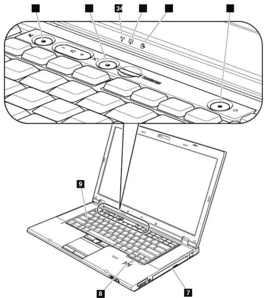
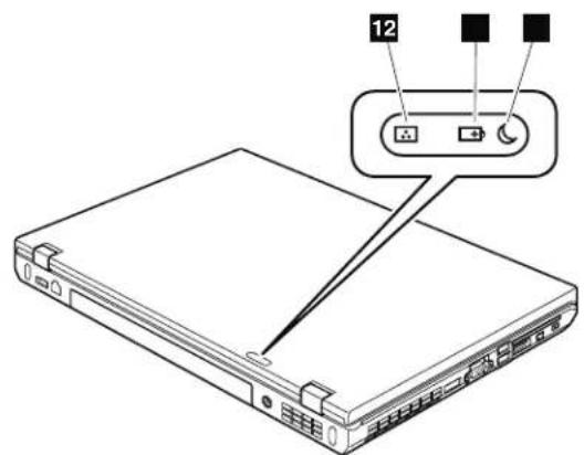
Table7.Statusindicators
| IndicatorMeaning | |
| 1 Speakermute | Orange: Thespeakerisonmute.Tosetthespeakererson muteorunmute,pressthespeakermutebutton. |
| 2 Microphone mute | Orange: Themicrophoneisonmute.Noneoftherecording devicesisavailablewhilethemicrophonemuteis onbydefault. |
| 3 WirelessLAN, WirelessWAN, orWiMAX status | Green: ThewirelessLANfeature(theIEEE802.11b/g standard,802.11a/b/g,or802.11n),wirelessWAN feature,orWiMaxfeatureison,andtheradiolink isreadyforuse. Blinkinggreen: Dataisbeingtransmitted. |
| 4 Bluetooth wirelessor WirelessUSB status | Green: TheBluetoothwirelessfeatureison,andtheradio linkisreadyforuse. Blinkinggreen: Dataisbeingtransmitted. |
| 5 Deviceaccess | Green: Dataisbeingreadfromorwrittentohetharddisk drive,thediskettedrive,orthedriveintheSerial UltrabayEnhanceddevice. Whenthisindicatoris on,donotputthecomputerintosleep(standby) modeorturnoffthecomputer. Note: Donotmovethesystemwhilethegreendevic accesslightison.Suddenphysicalshockcouldcausedrive errors. |
| 6 Poweron | Green: Thecomputerisonandreadytouse.This indicatorstayslitaroundthepower-onbutton wheneverthecomputerisonandisnotinsleep (standby)mode. |
| 7 SerialUltrabay Enhanced devicestatus | Green: ASerialUltrabayEnhanceddeviceisinstalledand inusec. Blinkinggreen: ASerialUltrabayEnhanceddeviceisinthe processofbeingdetached. Turnoff: ASerialUltrabayEnhanceddeviceisreadytobe attachedordetached. |
| 8 Fingerprint readerstatus | Green: The fingerprintreaderisreadytoswipe. Blinkinggreen: The fingerprintbeingauthenticatedorhasbeen authenticated. Blinkingorange: The fingerprintcouldnotbeauthenticated. |
| 9 Capslock | Green: CapsLockmodeisenabled.Toenablecordisable CapsLockmode,presstheCapsLockkey. |
| 10 Sleep(standby forWindows XP)status | Green: Thecomputerisinsleep(standby)mode. Blinkinggreen: The computerisenteringsleep(standby)modeor hibernationmode,orisresumingnormal operation. |
| 11 Batterystatus | Green: Thebatteryhasmorethan20%charge. Orange: Thebatteryhasbetween5%and20%charge. Fastblinkingorange: Thebatteryhaslessthan5%charge. Note:Thebatterymaybecharging. Slowblinkingorange: Thebatteryisbeingcharged.Whenitreaches20%, theblinkingcolorchangestogreen. Slowblinkinggreen: Thebatteryhasbetween20%and80%charge,and chargingdiscontinuing.Whenthebatteryreaches 80%charge,blinkingstops,butthechargimg may continueuntilthebatteryis100%charged. Note:Ifthecomputerisoperatingonbattery power,thebatterystatusindicatordoesnotwork whilethecomputeristurnedofforisleep (standby)modeorhibernationmode. Quickblinkingorange: Anerrorhasbeenoccurredinthebattery. Thebatterystatusindicatorisoff: Thebatterypackofthecomputerisdetached. |
| 12 Colorsensor status | Green: Calibrationiscomplete.Whenthalidisopened, theindicatorturnsoff. Blinkinggreen: Displaycolorsarebeingcalibrated. |
Fnkeycombinations
The following tables show the function of each combination of Fn with a function key.
Table8.Fnkeycombinations
| KeycombinationDescription | |
| Fn+F1Reserved. | |
| Fn+F2Lockthecomputer. | |
| Fn+F3Selectapowerplan(inWindowsXP,powerscheme)thathasbeencreatedbyPowerManager,oradjustthepowerlevelbyusingthes slidercontrol.Whenyoupressthiscombination,apanelforselectingapowerplan(powerscheme)appears.Notes: Tousethiscombinationofthekeys,ThinkPadPMdeviceredriver musthavebeeninstalledonthecomputer.IfyouhavenotoggonwithanadministratorsystemXP,andyoupressFn+F3,thepanelforselectingapowerscheme appears.IfyouhavenotoggonwithanotheruserIDinWindows XP,andyoupressFn+F3,thepaneldoesnotappear. | |
| Fn+F4Puttthecomputerinsleep(standby)mode.Toreturtonormal operation,presstheFnkeyonly,withoutpressingafunctionkey.Notes: Tousethiscombinationofthekeys,ThinkPadPMdeviceredriver musthavebeeninstalledonthecomputer.Ifyouwantousethecombinationtoputthecomputerinto hibernationmodeo一律nothingmode(inWindowsXP,shuttle the computerdownnorshowthepanelforturningoffthecomputer), changethesettingsinthePowerManager. | |
| Fn+F5Enableordisablethebuilt-inwirelessnetworkingfeatures.Ifyoupress Fn+F5,alistofwirelessfeaturesisdisplayed.Youcanquicklychange thepowerstateofeachfeatureintheilist.Note:IfyouwanttouseFn+F5toenableordisablethewireless features,thefollowingdevice Driversmustbeinstalledonthe computerbeforehand: ·PowerManagementdriver ·OnScreenDisplayUtility ·Wirelessdeviceredrivers | |
| Fn+F6Changethecaameraaandaudiosettings.WhenyoupressFn+F6,the cameraaandaudiosettingwindowisopenedandthecamerapreviewist turnedon. Note:Thecamerasettingsareaonlyappearsifthecomputerhasan integratedcamera. | |
| Fn+F7Applyapresen | tationschemesedirectly,withnoneedtostartPresentationDirector.TodisablethisfunctionandusetheFn+F7keycombinationforswitchingadisplayoutputlocation,startPresentationDirector,andchangethesettings.Note:IfthecomputerisanWindows7model,itdoesnotsupportpresentationschemes,howevertheFn+F7combinationmightstillbe usedtoswitchdisplayoutputlocation. |
| ForWindows7:Switchbetweenthecomputerdisplayanexternalmonitor.Windowswillshowthesedisplayoptions:•Computerdisplayonly(LCD)•Computerdisplayandexternalmonitor(sameimage)•Computerdisplayandexternalmonitor(extendeddesktopfunction)•ExternalmonitoronlyNote:Toswitchbetweenthecomputerdisplayanexternalmonitor,theWin+Pkeycombinationisalsoavailable.ForWindows VistaandWindowsXP:Switchbetweenthecomputerdisplayanexternalmonitor.Ifanexternalmonitorsattached,computeroutputisdisplayedinthe followingthreepatternsbyturns:•Externalmonitor(CRTdisplay)•Computerdisplayandexternalmonitor(LCD+CRTdisplay•Computerdisplay(LCD)Notes:Thisfunctionisnotsupportedifdifferentdesktopimagesaredisplayedonthecomputerdisplayandtheexternalmonitor(theExtenddesktopfunction).ThisfunctiondoesnworkwhileaDVDmovieoravideoclipsplaying.Toenablethisfunction,startPresentationDirector,andchangethesettings.Note:MultipleuserscanlogontoasingleoperatingsystembyusingdifferentuserIDs.Eachuserneedstodothefollowing:Click Start-->All Programs-->ThinkVantage-->PresentationDirector,andchangetheFn+F7settings. | |
| Fn+F8ChangethesettingsoftheUltraNav | pointingdevice. |
| Fn+F9Reserved. | |
| Fn+F10Reserved. | |
| Fn+F11Reserved. | |
| Fn+F12Puttthecomputerintohibernationmode.Toremturnonormaloperation, pressthepowerbuttonforlessthanfourseconds. Notes: Tousethiscombinaionofthekeys,ThinkPadPMdevicedriver musthavebeeninstalledonthecomputer. ThoughtscreenfadesoutimmediatelyafterFn+F12arepressed, thecomputerdoesnntenterthehibernationmodeimmediately.Do notmovethesystemmuntilthesleep(standby)statusindicatorstops blinking.Movingthecomputerwhenitisenteringhibernation mightcausecorruptionoftheharddiskdrive. | |
| Fn+PgUpTurntheThinkLight onoroff. Note:ThisfunctionissupportedonlyontheThinkPadNotebooksthat havetheThinkLight.TheonoroffstatusoftheThinkLightisshown onthescenforafewsecondswhenyoupressFn+PgUp. | |
| Fn+HomeThecomputeruterisplaybecomesbrighter. Thepurposeofthismethodistochangethebrightnesslevel temporarily.OnWindowsVista,thedefaultbrightnesslevelisloaded aftersleep(standby),hibernation,reboot,ordetachingorattachingan acadapter.Tochangethedefualtbrightnesslevel,changethesettings ofthePowerOptionintheControlPanelorusethePowerManager. | |
| Fn+EndThecomputeruterisplaybecomesdimmer. Thepurposeofthismethodistochangethebrightnesslevel temporarily.OnWindowsVista,thedefaultbrightnesslevelisloaded aftersleep(standby),hibernation,reboot,ordetachingorattachingan acadapter.Tochangethedefualtbrightnesslevel,changethesettings ofthePowerOptionintheControlPanelorusethePowerManager. | |
| Fn+SpacebarEnabletheFullScreenMagnifierfunction. | |
| Fn+PrtScHavethesamefunctionastheSysRqkey. | |
| Fn+ScrLkEnableordisablethenumerickeypad.Theindicatorofnumericlock willbedisplayedonthescreen. | |
| Fn+PauseHavethesamefunctionastheBreakkey. | |
| Fn+cursorkeysThesekeycombinationsworkwithWindowsMediaPlayer.Theyhave thefollowingfunctions: ·Fn+downnarrowkey:PlayerPause ·Fn+uparrowkey:Stop ·Fn+rightarrowkey:NextTrack ·Fn+leftarrowkey:PreviousTrack | |
FRUreplacement notices
This chapter presents notices related to removing and replacing parts. Read this chapter carefully before replacing any FRU.
Screwnotes
Loosescrewscancauseareliabilityproblem.IntheThinkPad Notebook,this problemisaddressedwithspecialnylon-coatedscrewsthathavethefollowing characteristics:
- Theymaintaintightconnections.
- Theydonoteasilycomeloose,evenwithshockorvibration.
- They are hardertotighten.
-Eachoneshouldbeusedonlyonce.
Dothe following when you service this machine:
- Keepthescrewkit(fortheP/N,see"Misce [aneousparts"onpage187)inyour toolbag.
- Alwaysuseneewscrews.
- Useatorquescrewdriverifyyouhaveone.
Tightenscrewsasfollows:
-Plastictoplastic
Turnanadditional90degreesafterthescrewheadtouchesthesurfaceofthe plasticpart:
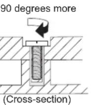
- Logiccardtoplastic
Turnanadditional180degreesafterthescrewheadtouchesthesurfaceofthe logiccard:
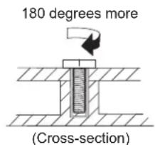
- Torquedriver
If you have a quad driver, refer to the "Torque" columnforeachstep.
- Makesurethatyouusethecorrectscrew.Ifyouhaveatorquescrewdriver, tightenallscrewsfirmlytothetorqueshowninthetable.Neveruseascrew thatyouremoved.Useanewone.Makesurethatallofthescrewsare tightenedfirmly.
- Ensuretorquescrewdriversarecalibratedcorrectlyfollowingcountry specifications.
Retainingserialnumbers
Thissectionincludesthefollowingdescriptions:
"Restoringtheserialnumberofthesystemunit"
"RetainingtheUUID"
"ReadingorwritingtheECAinformation"onpage83
Restoringtheserialnumberofthesystemunit
Whenthecomputerwasmanufactured,theEEPROMonthesystemboardwas loaded with the serial numbers of the systemmand all major components. These numbers need to remain the same throughout the life of the computer.
If you replace the system board, you must restore the serial number of the system unit to its original value.
Before replacing the systemboard, save the original serial number by doing the following:
1.InstalltheLENOVOThinkPadHardwareMaintenanceDisketteVersion1.76or later, and restart the computer.
2.Fromthemainmenu,select1.SetSystemIdentification.
3. Select2. ReadS/NdatafromEEPROM.
Theserialnumberofeachdeviceinyourcomputerisdisplayed;theserialnumber ofthesystemunitistlistedasfollows:
20:Serialnumber
Writedownthatnumber.
Note: Theserialnumberofthesystemunitisalsowrittenonthelabelattachedto thebottomofthecomputer.
After you have replaced the system board, restore the serial number by doing the following:
1.InstalltheLENOVOThinkPadHardwareMaintenanceDisketteVersion1.76or laterandrestartthecomputer.
2.Fromthemainmenu,select1.SetSystemIdentification.
3.Select1.AddS/NdatafromEEPROM.
Followtheinstructionsontheshcreen.
IftheMTmandProductIDnumbersdifferfromeachotherontherearlabel,use whatisshownfortheProductIDfield.Seeexamplebelow:
MTMonrearlabel:
TTTT-CTOS/NSSSSSSS
ProductIDonrearlabel:
TTTT-MMM(UsethisnumberwhensingSerialNumber)
Intheexample,theSerialNumbertobeinputis'1STTTTMMMSSSSSSS'.
RetainingtheUUID
TheUniversallyUniqueIdentifier(UUID)isa128-bitnumberuniquelyassignedto yourcomputeratproductionandstoredintheEEPROMofyoursystemboard.
Thealgorithm that generates the number is designed to provide unique IDs until theyear A.D.3400.Notwocomputers intheworld havethesamenumber.
When you're placing the systemboard, you must set the UUID on thenewsystem boards as follows:
1.InstalltheLENOVOThinkPadHardwareMaintenanceDisketteVersion1.76or later, and restart the computer.
2.Fromthemainmenu,select4.AssignUUID. AnewUUIDDiscreatedandwritten.IfvalidUUIDalreadyexists,itisnot overwritten.
ReadingorwritingtheECAinformation
InformationonEngineeringChangeAnnouncements(ECA)arestoredinthe EEPROMofthesystemboard.Theelectronicstorageofthisinformationsimplifies theprocedurotocheckiftheECAhasbeenpreviouslyappliedtoamachine.The machinedoesnotneedtobedissembledtocheckfortheECAapplication.
TocheckwhatECAshavebeenpreviouslyappliedtothemachine,usetheECA InformationRead/WritefunctionontheLENOVOThinkPadHardware MaintenanceDisketteVersion1.76orlater.
1.InserttheLENOVOThinkPadHardwareMaintenanceDisketteVersion1.76or later, and restart the computer.
2.Fromthemainmenu,select6.SetECAInformation.
3. To read ECA information, select 2. Read ECA/rework number from EEPROM and follow the instruction.
4. To read box build date, select 5. Read box build date from EEPROM, and follow the instruction on threscreen.
AfteranECAhasbeenappliedtothemachine,theEEPROMmustbeupdated to reflecttheECA'sapplication.UsetheLENOVOThinkPadHardwareMaintenance DisketteVersion1.76orlatertoupdatetheEEPROM.
Note:OnlytheECAnumberisstoredintheEEPROM.Themachinetypeofthe ECAisassumedbethesameasthemachinetypeofthemachinethathadtheECA appliedtoit.
1.InserttheLENOVOThinkPadHardwareMaintenanceDisketteVersion1.76or later, and restart the computer.
2.Fromthemainmenu,select6.SetECAInformation.
3. To write ECA information, select 1. Write ECA/rework number from EEPROM, andfollowtheinstruction.
4. To write box build date, select 4. Write box build date from EEPROM, and follow the instruction on thescreen.
Ifthesystemboardisbeingreplaced,trytoreadtheECAinformationfromtheold systemboardandtransfertheinformationtothenewsystem.Ifthesystemboard isinoperable,thiswillnotbepossible.
RemovingandreplacingaFRU
This chapter presents directions and drawings for use in removing and replacing a FRU. Besureto observ the following general rules:
1.Donottrytoserviceanycomputerunlessyouhavebeentrainedandcertified. Anuntrainedpersonrunstheriskofdamagingparts.
2.BeforereplacinganyFRU,review"FRUreplacement notices"onpage81.
3. Begin by removing any FRUsthavetoberremovedbeforethefailingFRU. AnysuchFRUsarelistedatthetopofthepage.Removethemintheorderin whichtheyarelisted.
4.FollowthecorrectsequenceinthestepsforremovingtheFRU,asgiveninthe drawingsbythenumbersinsquarecallouts.
5. WhenturningascrewtoplaceaFRU, turnitinthedirectionasgivenby the arrowinthedrawing.
6. When removing the FRU, move it in the direction as given by the arrow in the drawing.
7.ToputthenewFRUinplace,reversetheremovalprocedureandfollowany notesthatpertaintoreplacement.Forinformationaboutconnecting and arranginginternalcables,see"Lpcations"onpage137.
8. When replacing a FRU, use the correct screwwath in the procedures.

DANGER
BeforeremovinganyFRU,turnoffthecomputer,unplugallpowercords fromelectricaloutlets,removethebatterypack,andthendisconnectany interconnectingcables.
Attention: After replacing a FRU, don't turn on the computer until you have madesurethatall'screws, springs, and othersmallpartsareinplaceandnone are looseinsidethecomputer. Verify this by shaking the computer gently and listening for rattling sounds. Metallic parts or metal flakes can cause electrical short circuits.
Attention: Thesystemboarddissensitiveto, and canbedamagedby, electrostatic discharge. Beforetouchingit, establish personal grounding by touchingaground pointwithonehandorbyusinganelectrostaticdischarge(ESD) strap(P/N 6405959).
BeforeservicingThinkPadT510,T510i,andW510
Table9. RemovalstepsofSIMcard
SomemodelsoftheThinkPadT510,T510i,andW510youareservicingmighthave theSIMcardthatthecustomerhasinstalled.
If the computer you are servicing has the SIM card, remove it before you start the servicing.
ToremovetheSIMcard,youneedtoremovethebatterypackfirst.(See"1010 Batterypack"Onpage87.)

After you finish the servicing, makes sure that you insert the cardback into the slot firmly.
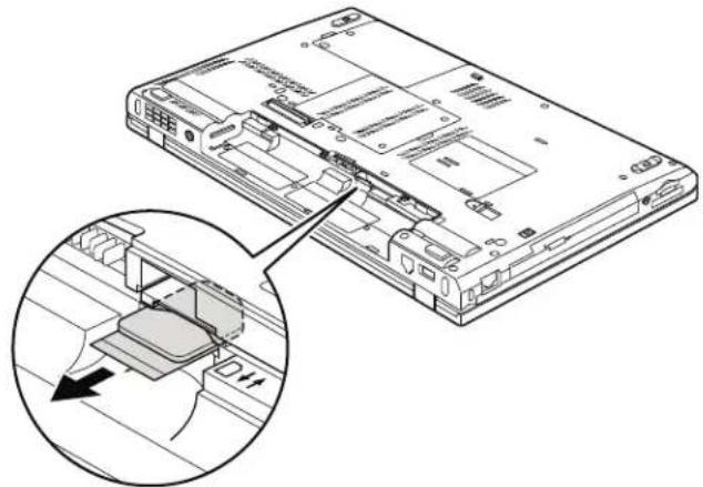
1010Batterypack
Importantnoticeforreplacingabatterypack:
ThinkVantageToolbox(inWindows7)andLenovoSystemToolbox(inWindows Vista and Windows XP) have an automatic battery diagnosis that determines if the battery pack is defective. Abatterypack FRU should not be replaced unless this diagnostic showsthat the battery is defective.
Theonlyexceptiontothisisifthebatterypackisphysicallydamagedora customerisreportingapossiblesafetyissue.
IfThinkVantageToolboxorLenovoSystemToolboxisnotinstalledinthe computer, the customers should download this program before anon-physically damaged batterypack is replaced. Notethat physically damaged batterypack is non-warrantyreplacement.
Table10. Removalstepsofbatterypack

DANGER
Useonlythebatteryspecifiedinthepartlistforyourcomputer.Anyother batterycouldigniteoreexplode.
Unlockthebatterylatch 1 . Holding the batterylatch in the unlocked position 2 ,remove the batterypack in the directions shown by arrow 3 .
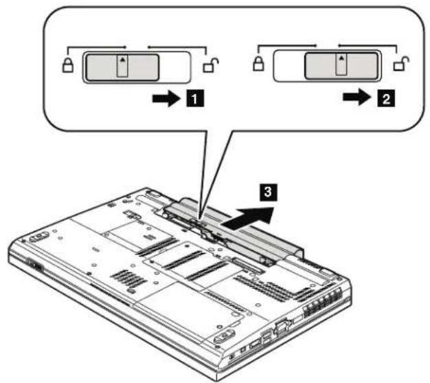
Wheninstalling:Installthebatterypackintheslot,andthenmakesurethat thebatterylatchthisinthellockedposition.
1020SerialUltrabayEnhanceddeviceortravelbezel
Foraccess,removethisFRU:
"010Batterypack"onpage87
Table11. RemovalstepsofSerialUltrabayEnhanceddeviceortravelbezel
Holdingthebaylocklatchintheunlockedposition 1, slidethebayejectlatch 2, and then pullouttheSerialUltrabayEnhanceddeviceorthetravelbezelin thedirections shown by arrow 3.
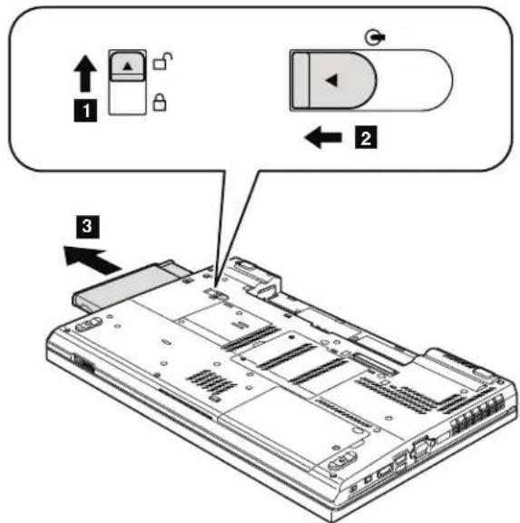
1030DIMMslotcover
Foraccess,removethisFRU:
"010Batterypack"onpage87
Table12. RemovalstepsofDIMMslotcover
Note:Loosenthescrews 1,butdonotremovethem.
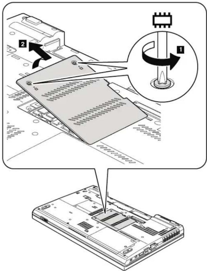
1040DIMM(bottomslot)
Foraccess,removetheseFRUsinorder:
Table13. RemovalstepsofDIMM(bottomslot)
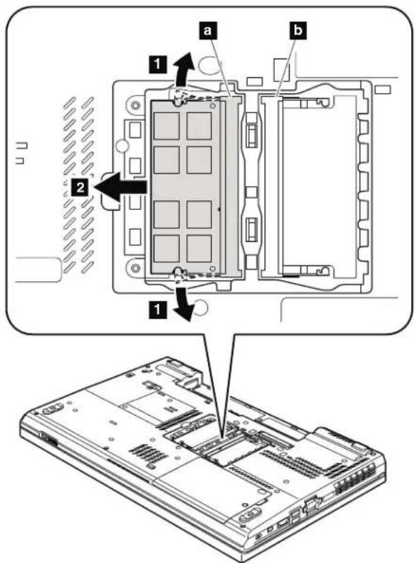
Note:IfonlyoneDIMMisusedonthecomputeryouareservicing,thecard mustbeinstalledinSLOT-0(a),butnotinSLOT-1(b).
Wheninstalling:InsertthenotchedendoftheDIMMminthesocket.Pressthe DIMMfirmly,andpivotituntilitsnapsintotheplace.Makesurethatitis firmlyixedintheslotanddoesnotmoveeasily.
1050Harddiskdriveslotcover,hardiskdrive(HDD)andHDDrubber railsorSolidstatedrive(SSD)andstorageconverter
Foraccess,removethisFRU:
"010Batterypack"onpage87
Attention:
- Do not drop the drive or apply any physical shock to it. The drive is sensitivetophysicalshock.Improperhandlingcauseddamageand permanentlossofdata.
- Beforeeremovingthedrive,havetheusermakeabackupcopyofallthe informationonitifpossible.
- Neverremovethedrivewhilethesystemisoperatingorisinsuspendmode.
Table14. Removalstepsofharddiskdriveslotcover,HDDandHDDrubberrailsorSSD andstorageconverter
Note:Loosenthescrew 1,butdonotremoveit.
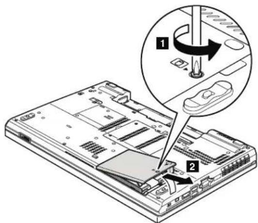
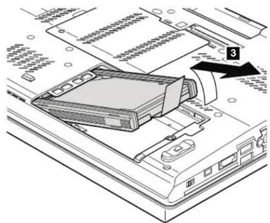
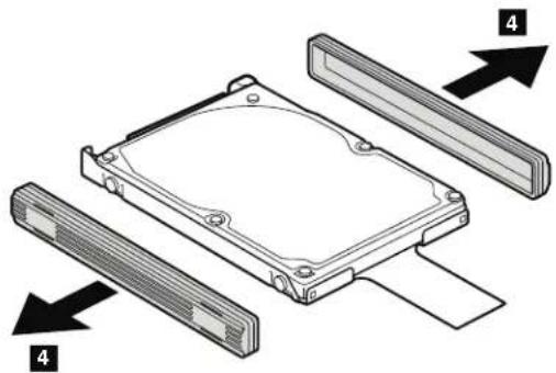
Table15. RemovalstepsofHDDandHDDrubberrails
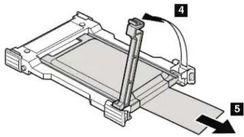
Table16. RemovalstepsofSSDandstorageconverter
Wheninstalling: Makes sure that the SSD connector or HDD connector is attached firmly.
1060Keyboard
Foraccess,removetheseFRUsinorder:
"1010Batterypack"onpage87
1030DIMMMslotcover"onpage89
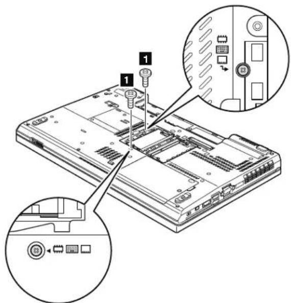
Table17.Removalstepsofkeyboard
| StepScrew(quantity)ColorTorque | ||
| M2×14mm,wafer-head,nylon-coated(2)Black0.181Nm | (1.85kgfcm) | |
Table17. Removalstepsofkeyboard(continued)
Pushdownthekeyboardalittle toward the arrow 2 until the front edge of the keyboard is detached from the keyboard bezel.
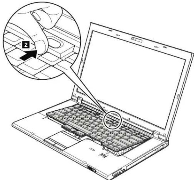
Liftthekeyboardalittleinthedirectionshownbyarrow 3 ,andthendetach theconnector 4 .
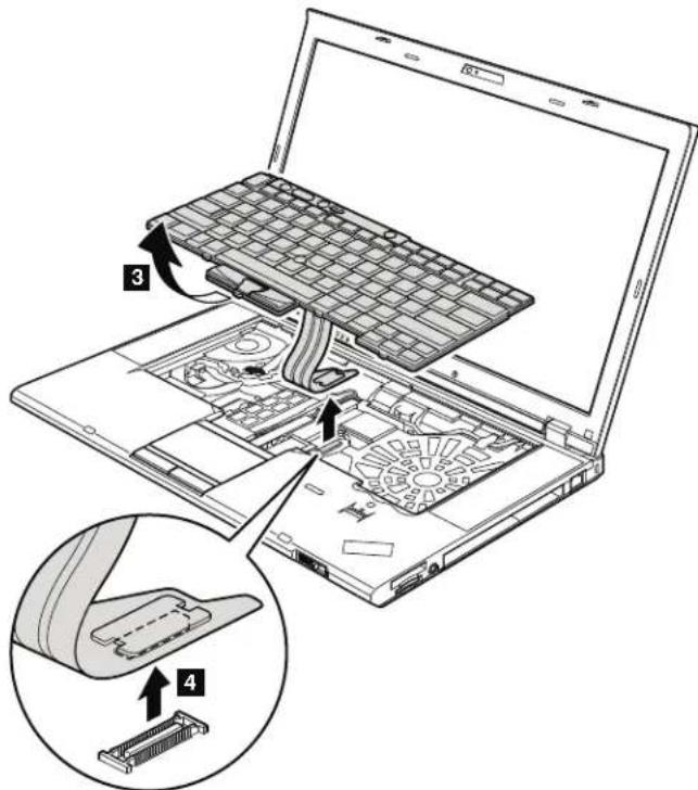
Wheninstallingthekeyboard,doasfollows:
Table18.Installationstepsofkeyboard
- Attachthekeyboardconnector 1.
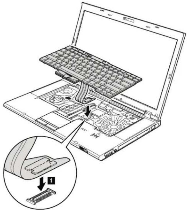
- Attachthekeyboardsothatthekeyboardedges areundertheframeas showninthisfigure.
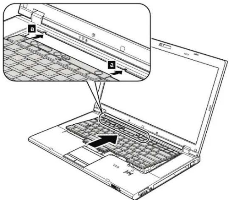
Table18.Installationstepsofkeyboard(continued)
3.Gentlypressthekeyswithyourthumbsandtrytoslidethekeyboardtoward you.
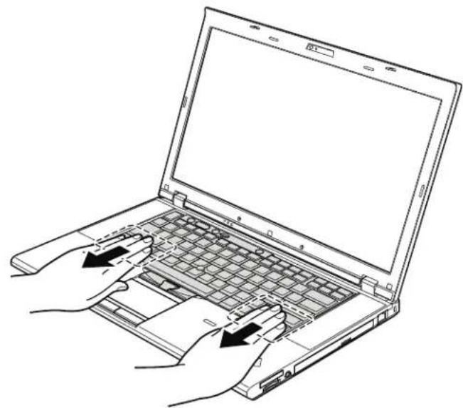
- Makesurethatthefrontsideofthekeyboard(b)ishousedfirmly.
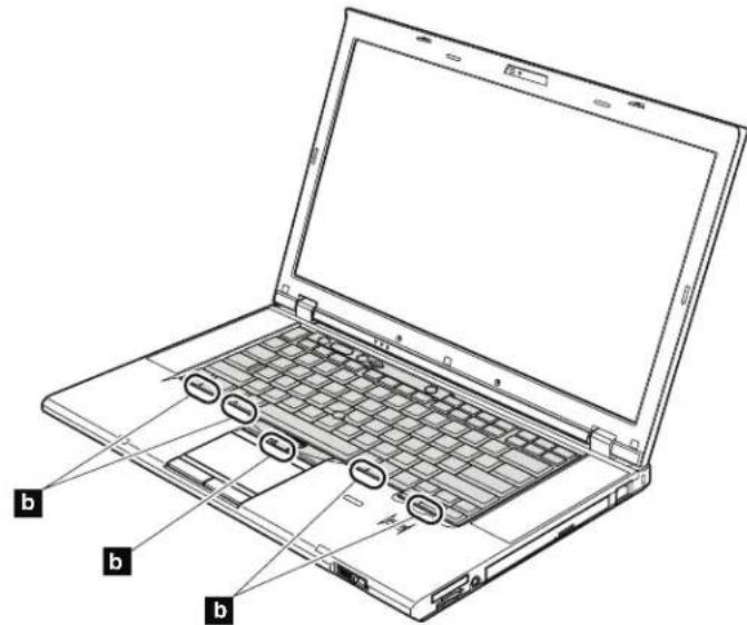
5.Securethekeyboardbytighteningthescrewsfromthebottomsideofthe computer.
1070DIMM(upperslot)
Foraccess,removetheseFRUsinorder:
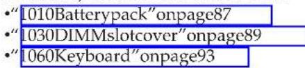
Table19. RemovalstepsofDIMM(upperslot)
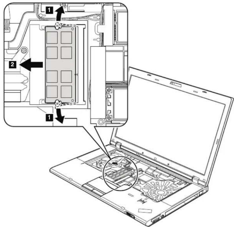
Note:IfonlyoneDIMMisusedonthecomputeryouareservicing,thecard mustbeinstalledinSLOT-0(a),butnotinSLOT-1(b).
Wheninstalling:InsertthenotchedendoftheDIMMminthesocket.Pressthe DIMMfirmly,andpivotituntilitsnapsintotheplace.Makesurethatitis firmlyfixedintheslotanddoesnnotmoveeasily.
1080PCIExpressMiniCardforwirelessLAN
Foraccess,removetheseFRUsinorder:
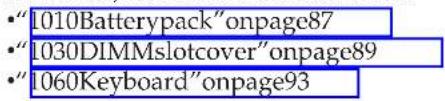
Table20. RemovalstepsofPCIExpressMiniCardforwirelessLAN
Instep 1, unplugthejacksbyusingtheremovaltoolantennaRFconnector (P/N:08K7159)orpicktheconnectorswithyourfingersandgentlyunplug themindirectionofthearrow.
Note:Somemodelsmighthaveonlytwoantennacablesinstep 1.
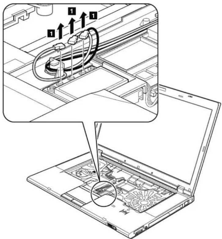
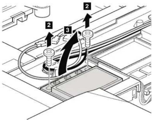
Table20. RemovalstepsofPCIExpressMiniCardforwirelessLAN(continued)
Table20. RemovalstepsofPCIExpressMiniCardforwirelessLAN(continued)
Wheninstalling:
- InmodelswithwirelessLANcardthasthastwoantennaconnectors, plug the gray cable into the jack labeled MAIN or M, and the black cable into the jack labeled AUX or A on the card. If the computer you are servicing has three cables, put the white cable inthecableprotectiontubeas shown in this figure.
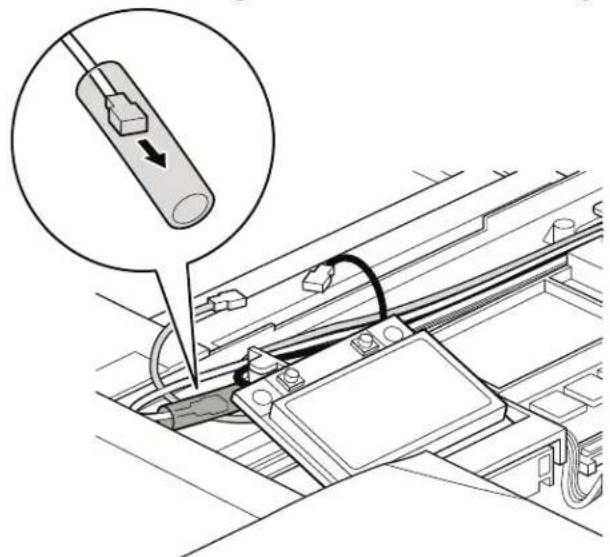
- InmodelswithwirelessLANcardthathasthreeantennaconnectors,plugthe graycable(MAIN)intothejacklabeledTR1, the whitecable(3rd) intojack labeled RO or TR3, and the black cable (AUX) into jack labeled TR2 on the card.
1090PCIExpressMiniCardforwirelessWAN
Foraccess,removetheseFRUsinorder:
"1010Batterypack"onpage87
1030DIMMMslotcover"onpage89
1060Keyboard"onpage93
Table21. RemovalstepsofPCIExpressMiniCardforwirelessWAN
Instep 1, unplugthejacksbyusingtheremovaltoolantennaRFconnector (P/N:08K7159)orpicktheconnectorswithyourfingersandgentlyunplug themindirectionofthearrow.
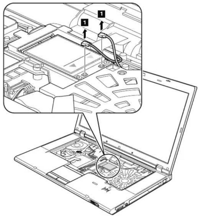
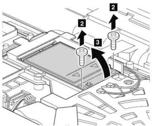
Table21. RemovalstepsofPCIExpressMiniCardforwirelessWAN(continued)
| StepScrew(quantity)ColorTorque | ||
| M2×3mm,wafer-head,nylon-coated(2)Silver0.181Nm | (1.85kgfcm) |
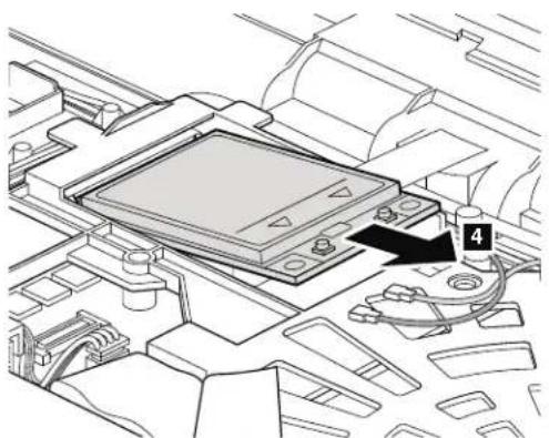
Note: Plug the orange cable into the jack labeled MAIN, and the blue cable into the jacklabeledAUXonthecard.
1100Keyboardbezelassembly
Foraccess,removetheseFRUsinorder:
"1010Batterypack"onpage87
1030DIMMMslotcover"onpage89
1060Keyboard"onpage93
Attention:Beforeeremovingthekeyboardbezelassembly,makesurethatyou haveremovedExpressCardblankbezeloranycardintheslot.
Table22. RemovalstepsofExpressCardblankbezelerExpressCard
WhenyoupresstheExpressCardblankbezelerExpressCard 1, it popsout 2.
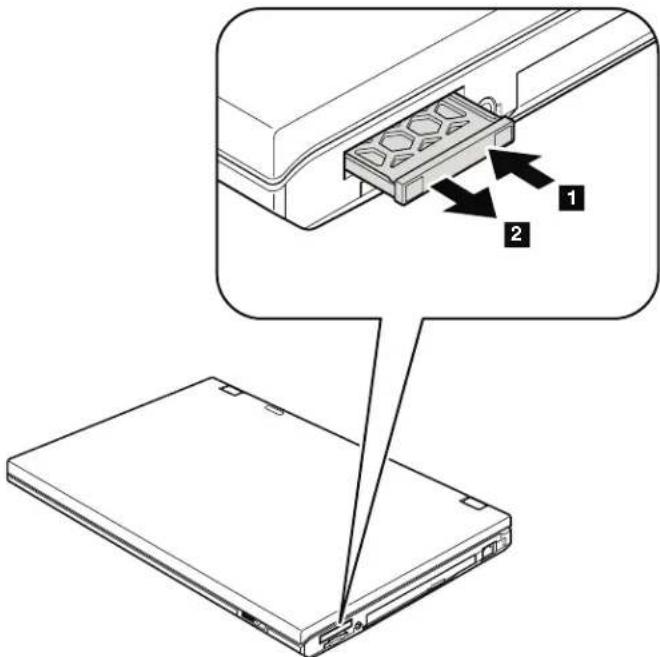
Table22. RemovalstepsofExpressCardblankbezelerExpressCard(continued)
Wheninstalling: Makesurethatthebezelorthecardiscorrectlyorientedas showninthisfigure.
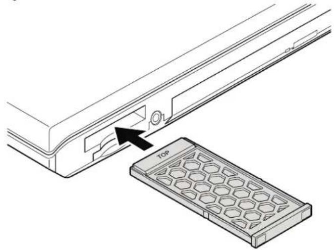
Table23. Removalstepsofkeyboardbezelassembly
Note:Thespeakerassemblyisattachedtothekeyboardbezel.
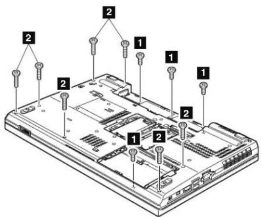
| StepScrew的数量(M) | StepScrew的尺寸(mm) | StepScrew的材质(铜或铝) | StepScrew的材料(镍或钴) |
| 1 M2×4mm,bind-head,nylon-coated(4)Black0.181Nm | (1.85kgfcm) | ||
| 2 M2×14mm,bind-head,nylon-coated(7)Black0.181Nm | (1.85kgfcm) | ||
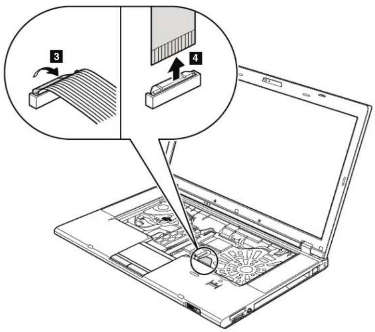
Table23. Removalstepsofkeyboardbezelassembly(continued)
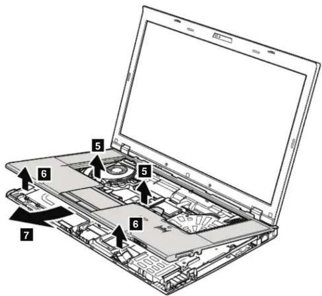
1110Bluetoothdaughtercard(BDC-2.1)
Foraccess,removetheseFRUsinorder:
Table24. RemovalstepsofBDC-2.1
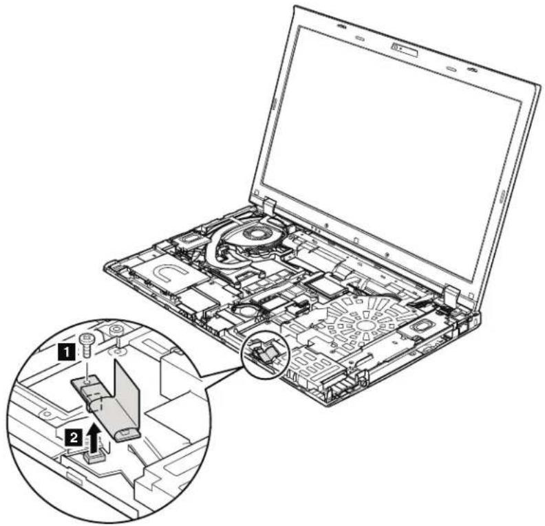
| StepScrew(quantity)ColorTorque | ||
| M2×3mm,wafer-head,nylon-coated(1)Silver0.181Nm | (1.85kgfcm) |
Wheninstalling: Makesurethattheconnectorisattachedfirmly.
1120Backupbattery
Foraccess,removetheseFRUsinorder:
1010Batterypack"onpage87
1030DIMMMslotcover"onpage89
060Keyboard"onpage93
100Keyboardbezelassembly"onpage103

DANGER
Useonlythebatteryspecifiedinthepartlistforyourcomputer.Anyother batterycouldigniteoreexplode.
Table25. Removalstepsofbackupbattery
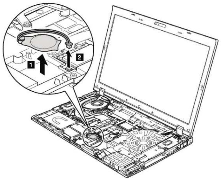
Wheninstalling: Makesurethatthebatteryconnectorisattachedfirmly.
1130SmartCardorContactlessSmartCardorSmartCarddummy spacer
Foraccess,removetheseFRUsinorder:
1010Batterypack"onpage87
1030DIMMMslotcover"onpage89
1060Keyboard"onpage93
100Keyboardbezelassembly"onpage103
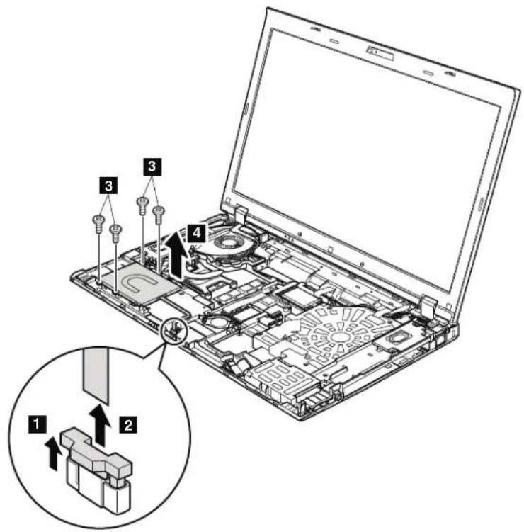
Table26. RemovalstepsofSmartCard
| StepScrew(quantity)ColorTorque | |||
| M2 | 3mm,wafer-head,nylon-coated(4)Silver0.181N | m | (1.85kgfcm) |
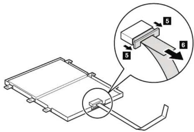
Table26. RemovalstepsofSmartCard(continued)
Table27. RemovalstepsofdummycardandContactlessSmartCard
| StepScrew(quantity)ColorTorque | |||
| M2 | 3mm,wafer-head,nylon-coated(4)Silver0.181N | m | (1.85kgfcm) |
Table27. RemovalstepsofdummycardandContactlessSmartCard(continued)
Table28. Removalstepsofdummycardandspacer
| StepScrew(quantity)ColorTorque | ||
| M2×3mm,wafer-head,nylon-coated(4)Silver0.181Nm | (1.85kgfcm) |
1140Speakerassembly
Foraccess,removetheseFRUsinorder:
"1010Batterypack"onpage87
1030DIMMMslotcover"onpage89
1060Keyboard"onpage93
100Keyboardbezelassembly"onpage103
Table29. Removalstepsofspeakerassembly
| StepScrew(quantity)ColorTorque | |||
| M2×3mm,wafer-head,nylon-coated(4)Silver0.181Nm | (1.85kgfcm) | ||
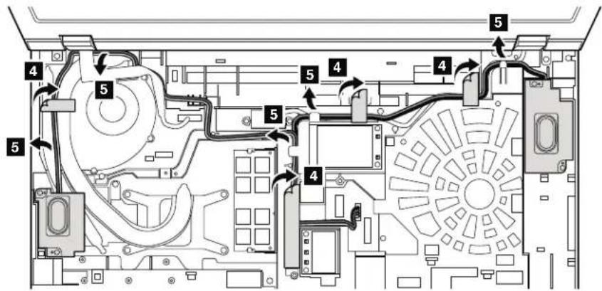
Table29. Removalstepsofspeakerassembly(continued)
Wheninstalling: Makesurethatthespeakerconnectorisattachedfirmly. Then routethecablesandsecurethemproperlyasshowninthefigureabove.
1150Thermalmodule
Foraccess,removetheseFRUsinorder:
"1010Batterypack"onpage87
1030DIMMMslotcover"onpage89
060Keyboard"onpage93
100Keyboardbezelassembly"onpage103
140Speakerassembly"onpage111
Table30. Removalstepsofthermalmodule
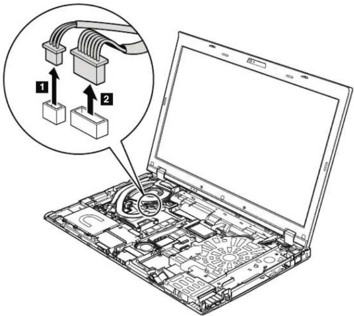
Wheninstalling: Makesurethattheconnectorsareattachedfirmly.
Note: Loosen the screws 4a to 4d in order, but do not remove them. Some modelsdonothavescrews .Forthosemodels,skipthestep 5.
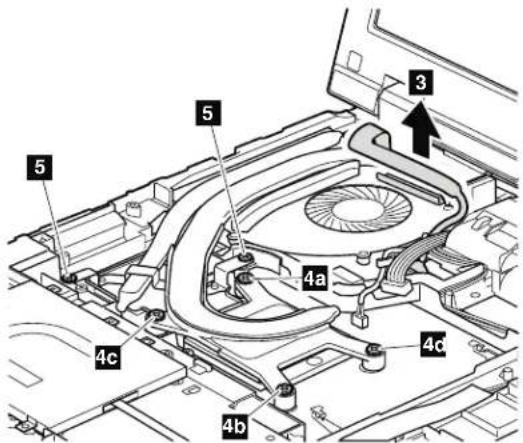
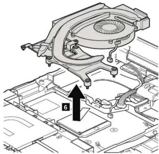
Table30. Removalstepsofthermalmodule(continued)
Wheninstalling:Beforeyouattachthefanassemblytothecomputer,apply thermalgrease,atanamountof0.2grams,onthepartsmarked a asinthe followingfigures.Eithertoomuchortoolessapplicationofgreasecancausea thermalproblemduetoimperfectcontactwithacomponent.ForthenewCPU thermaldevice/fan,youneedtopeelthethinfilmofffromtherubbersmarked b.
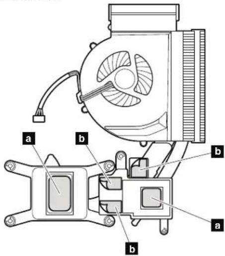
ForSwitchableGraphicsmodels:
Table30. Removalstepsofthermalmodule(continued)
ForIntegratedGraphicsmodels:
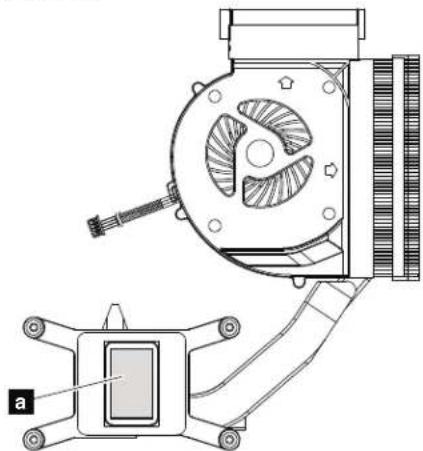
ForWorkstationmodels:
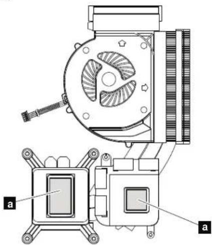
1160CPU
Foraccess,removetheseFRUsinorder:
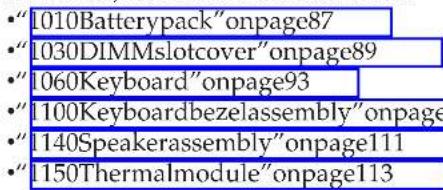
Attention:CPUisextremelysensitive. When you use the CPU, avoid any kind of rough handling.
Table31. RemovalstepsofCPU
Rotatetheheadofthescrewinthedirectionshownbyarrow 1 toreleasethe lock;thenremovetheCPU 2.
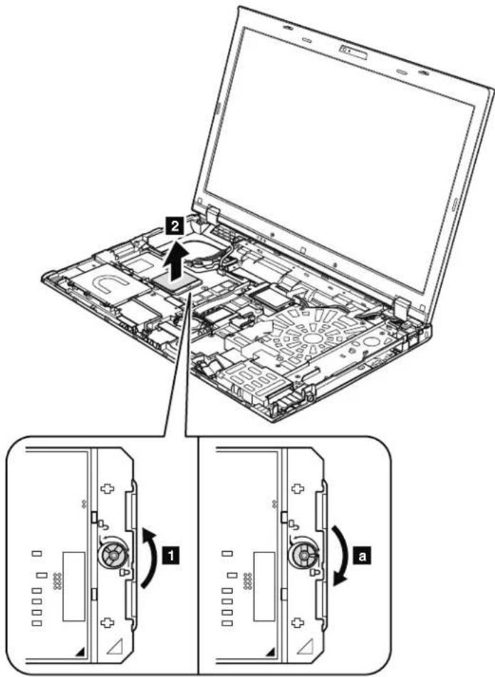
Wheninstalling:Place the CPU on the CPU socket, and then rotate the head of the screwin the directions shown by arrow a to secure the CPU.
1170LCDUnit
Foraccess,removetheseFRUsinorder:
"1010Batterypack"onpage87
1030DIMMMslotcover"onpage89
050Harddiskdriveslotcover,harddiskdrive(HDD)andHDDrubberrails orSolidstatedrive(SSD)andstorageconverter"onpage91
"060Keyboard"onpage93
1080PCIExpressMiniCardforwirelessLAN"onpage98
- "1090PCIExpressMiniCardforwirelessWAN"onpage101
100Keyboardbezelassembly"onpage103
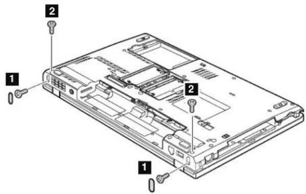
Table32. RemovalstepsofLCDunit
| StepScrew | ewcapScrew | (quantity)ColorTorque | ||
| 1 | O | M2.5×6mm,wafer-head, nylon-coated(2) | Black0.392Nm (4.0kgfcm) | |
| 2 | M2.5×6mm,wafer-head, nylon-coated(2) | Black0.392Nm (4.0kgfcm) | ||
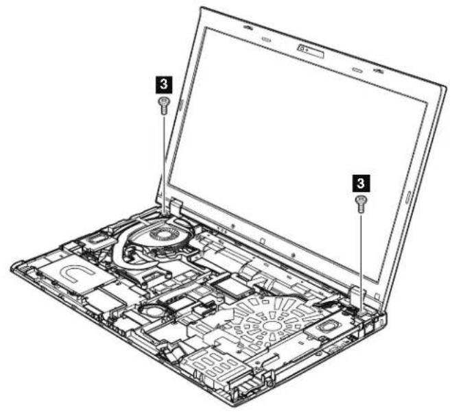
Table32. RemovalstepsofLCDunit(continued)
| StepScrew的数量(M) | 3 | 5×6mm,wafer-head,nylon-coated(2)Black0.392 | Nm | (4.0kgfcm) |
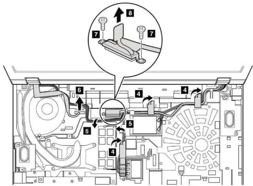
Table32. RemovalstepsofLCDunit(continued)
| StepScrew(quantity)ColorTorque | |||
| M2 | 4mm,wafer-head,nylon-coated(2)Black0.181N | m | (1.85kgfcm) |
Wheninstalling:
-
MakesurethatyouattachtheLCDconnectorfirmly.
-
Makesurethatouroutethecablesfirmlyandtapeupintheproper positionsasshowninthisfigure.
-
When youroutethecables, makesurethattheyarenotsubjectedtoany tension. Tensioncouldcausethecablestobedamagedbythecableguidides, or awiretobebroken.
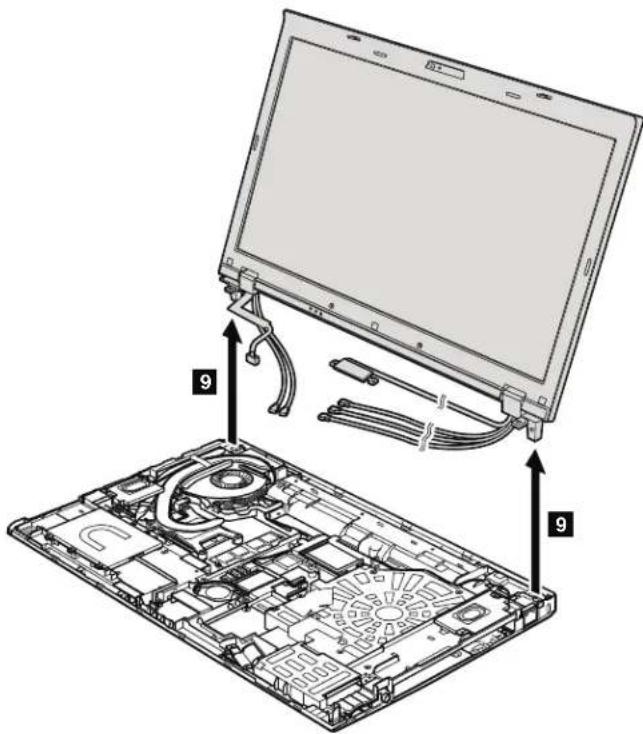
Table32. RemovalstepsofLCDunit(continued)
1180Basecoverassembly
Foraccess,removetheseFRUsinorder:
1010Batterypack"onpage87
1020SerialUltrabayEnhanceddeviceortravelbezel"onpage88
030DIMMMslotcover"onpage89
1050Harddiskdriveslotcover,harddiskdrive(HDD)andHDDrubberrails
orSolidstatedrive(SSD)andstorageconverter"onpage91
1060Keyboard"onpage93
1080PCIExpressMiniCardforwirelessLAN"onpage98
1090PCIExpressMiniCardforwirelessWAN"onpage101
100Keyboardbezelassembly"onpage103 1110 Bluetooth daughter card (BDC-2.1)" on page 106
1120Backupbattery"onpage107 1130SmartCardorContactlessSmartCardorSmartCarddummyspacer"on page108
1140Speakerassembly"onpage111
"1150Thermalmodule"onpage113
1170LCDunit"onpage117
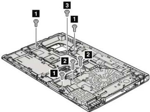
Table33. Removalstepsofbasecoverassembly
| StepScrew (quantity) Color Torque | |||
| 1 M2 | 7mm,wafer-head,nylon-coated(3)Silver0.181Nm | (1.85kgfcm) | |
| 2 | M2 × 14 mm, wafer-head, nylon-coated (2) | Black | 0.181 Nm (1.85kgfcm) |
| 3 | M2 × 4 mm, wafer-head, nylon-coated (1) | Black | 0.181 Nm (1.85kgfcm) |
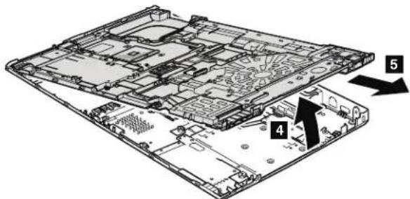
Table33. Removalstepsofbasecoverassembly(continued)
Note:Applyinglabelstothebasecover
ThenewbasecoverFRUisshippedwithakitcontaininglabelsofseveralkinds.
Whenyourereplacethebasecover,youneedtoapplythefollowinglabels:
FCClabel
14 Homologationlabel
15 Serialnumberlabel
Followinglabelsneedtobepeeledofffromtheoldbasecover,andneedtobeputonthenewbasecover.
1 Windowslicenselabel(COA)
2 Informationlabel
3 IMElbarcodelabel
4 Macaddresseslabel
VodafoneLabel
6 Israellabel
7 Modemlabel(onlyforPRCmodels)
8 ChinawirelessWANlabel
9 ModemAMOMlabel(onlyforBrazil)
10 Bluetoothlabel(onlyforBrazil)
11 Wirelesscardlabel(onlyforBrazil)
12 SIRIMlabel
16 Assettaglabel
Forsomemodels,youalsoneedtoapplyoneortwoFCClabels. Checktheold basecover;ifithasoneortwoFCClabels,findduplicatesoftheminthelabel kitandapplythemtothenewbasecover.
Forthelocationofeachlabel,referthefollowingfigure:
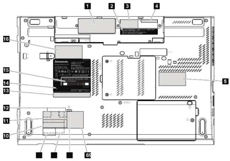
1190I/Osubcard
Foraccess,removetheseFRUsinorder:
Table34. Removalstepsofi/Osubcard
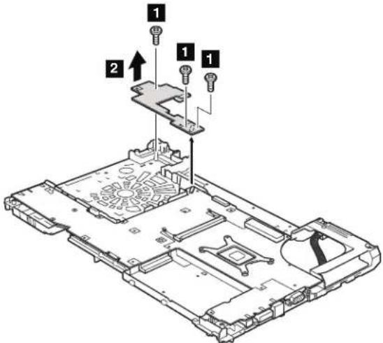
| StepScrew(quantity)ColorTorque | ||
| M2x7mm,wafer-head,nylon-coated(3)Silver0.181Nm | (1.85kgfcm) |
Wheninstalling: Makesurethattheconnectorisattachedfirmly.
1200Systemboardassemblyandmagnesiumstructureframe
Foraccess,removetheseFRUsinorder:
"1010Batterypack"onpage87
"020SerialUltrabayEnhanceddeviceortravelbezel"onpage88
"1030DIMMMslotcover"onpage89
1040DIMM(bottomslot)"onpage90
1050Harddiskdriveslotcover,harddiskdrive(HDD)andHDDrubberrails orSolidstatedrive(SSD)andstorageconverter"onpage91
1060Keyboard"onpage93
1070DIMM(upperslot)"onpage97
"080PCIExpressMiniCardforwirelessLAN"onpage98
"[090PCIExpressMiniCardforwirelessWAN"onpage101
"1100Keyboardbezelassembly"onpage103
- "1110 Bluetooth daughter card (BDC-2.1)" on page 106
"1120Backupbattery"onpage107
"130SmartCardorContactlessSmartCardorSmartCarddummyspacer"on page108
"I140Speakerassembly"onpage111
"1150Thermalmodule"onpage113
"1160CPU"onpage116
"IT70LCDunit"onpage11
"[180Basecoverassembly"onpage121
"[1901/Osubcard"onpage124
Important notices for RAID setting:
Beforeyoureplacethesystemboard,makesurethatyouread"InstallingandconfiguringRAID"onpage71,andhavethenecessaryyinformation.
After you're placed the systemboard, RAID mode is recovered as default. To confirm the SATA amodesetting, you can see the setting in BIOSSetup Utility menus as follows:
Config -> Serial ATA (SATA) -> SATA Controller Mode Option -> Compatibility/AHCI/RAID
Important notices for handling the systemboard:
Whenhandlingthesystemboard,bearthefollowinginmind.
- Thesystemboardhasanaccelerometer, which can be broken by applying severalthousandsofG-forces.
Note: Dropping asystemboardfromaheightoffaslittleas6inchessothatit fallsflatonahardbenchcansubjectttheaccelerometertoasmuchas6,000G's ofshock.
- Becarefulnottodropthesystemboardonabenchtopthathasahard surface, suchasmetal, wood, or composite.
-Ifasystemboardisdropped,youmusttestit,usingPC-DoctorforDOS,to makesurethattheHDDActiveProtectionstillfunctions(seebelow).
Note:If the testshowsthatHDDActiveProtectionisnotfunctioning, besure todoumentthedropinanyrejectreport,andreplacethesystemboard.
-
Avoidroughhandlingofanykind.
-
Ateverypointintheprocess, besurenottodroporstackthesystemboard.
-
Ifyouputasystemboarddown,besuretoputiononlyonapaddedsurface suchasanESDmotorconductivecorrugatedmaterial.
Afterreplacingthesystemboard,runPC-DoctorforDOStomakesurethat HDDActiveProtectionstillfunctions.Theprocedureisasfollows:
1.Placethecomputerahorizontalsurface.
- Run Diagnostics ThinkPad Devices HDD Active Protection Test.
Attention: Donotapplyphysicalshocktothecomputerwhilethetestis running.
Table35.Locationofmajorssensitivecomponentsonthesystemboard
Following componentssolderedonthetopsideofthesystemboardare extremelysensitive.Whenyouservicethesystemboard,avoidanykind of roughhandling.
a MCP(MultiChipPackage)processor
PCH(PlatformControllerHub)
AccelerometerchipfortheHDDActiveProtectionSystem
d Graphics
Note: d (Graphics)isonlyfortheSwitchableGraphicsmodelsand Workstationmodels.ThesystemboardinIntegratedGraphicsmodels doesnothingthischip.
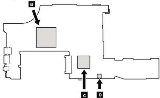
Table35.Locationofmajorssensitivecomponentsonthesystemboard(continued)
ForIntegratedGraphicsmodels:
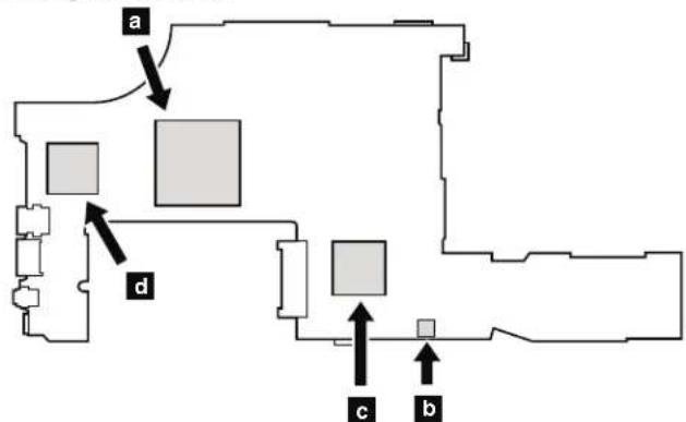
ForSwitchableGraphicsmodels:
ForWorkstationmodels:
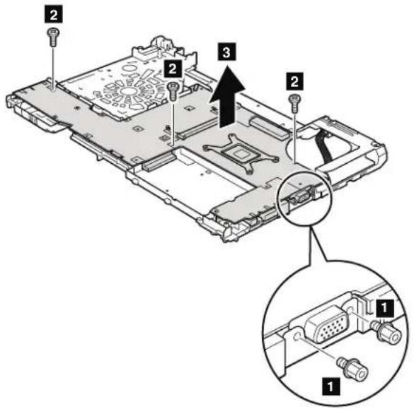
Table36. Removalstepsofsystemboardandmagnesiumstructureframe
| StepScrew(quantity)ColorTorque | ||
| 1 Hexstud,nylon-coated(2)Silver0.392Nm | (4.0kgfcm) | |
| 2 M2×7mm,wafer-head,nylon-coated(3)Silver0.181Nm | (1.85kgfcm) |
Wheninstalling:Whenyoureplacethesystemboard,attachthermalrubbersas showninthisfigure.Dependonthemodelsyouareservicing,thenumberof thermalrubbersaredifferent.Checkthethermalrubbersontheoldsystem board,andfindduplicatesoftheminthenthewFRUpackageandapplythemto thenewsystemboard.
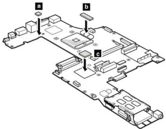
2010LCDbezelassembly
Foraccess,removethisFRU:
"010Batterypack"onpage87
Table37. RemovalstepsofLCDbezelassembly
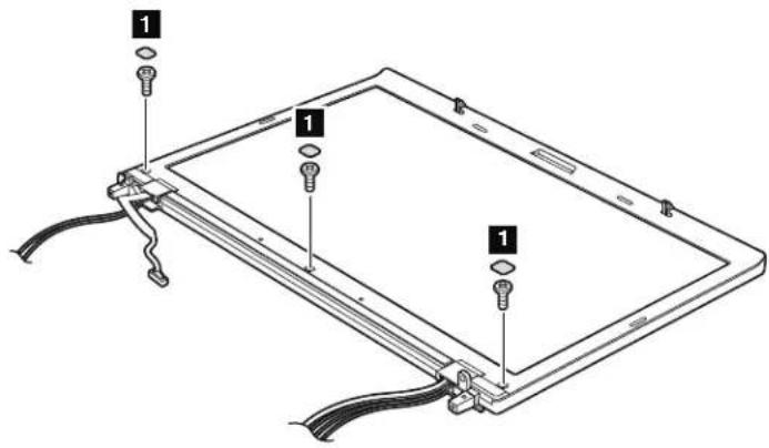
| StepScrew | ewcapScrew | (quantity)ColorTorque | ||
| 1 | ☐ | M2.5×6mm,wafer-head, nylon-coated(3) | Black0.392N | Nm (4.0kgfcm) |
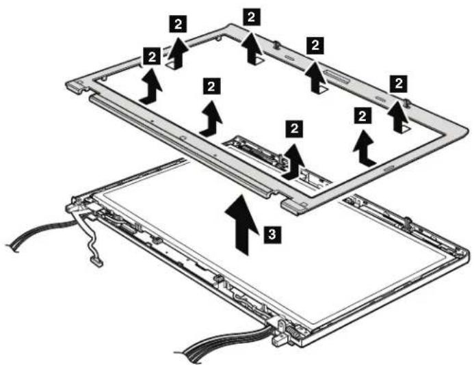
Wheninstalling: Makesurethatallthelatchesareattachedfirmly.
2020LEDsubcard
Foraccess,removetheseFRUsinorder:
"010Batterypack"onpage87
2010LCDbezelassembly"onpage129
Table38. RemovalstepsofLEDsubcard
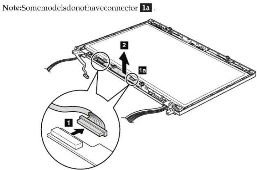
Wheninstalling: Makesurethattheconnectorsareattachedfirmlyandthecard isinstalledasshowninthisfigure.
2030Integratedcamera
Foraccess,removetheseFRUsinorder:
"1010Batterypack"onpage87
"2010LCDbezelassembly"onpage129
Table39. Removalstepsofintegratedcamera
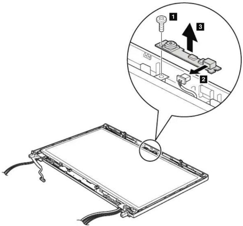
| StepScrew(quantity)ColorTorque | |||
| M2 | 3mm,wafer-head,nylon-coated(1)Silver0.181N | Nm | (1.85kgfcm) |
Wheninstalling: Makesurethattheconnectoroftheintegratedcameras is attachedfirmly.
2040LCDcable,cameracable,LCDpanel,andhinges
Foraccess,removetheseFRUsinorder:
"1010Batterypack"onpage87
1030DIMMMslotcover"onpage89
1050Harddiskdriveslotcover,harddiskdrive(HDD)andHDDrubberrails orSolidstatedrive(SSD)andstorageconverter"onpage91
1060Keyboard"onpage93
1080PCIExpressMiniCardforwirelessLAN"onpage98
"1090PCIExpressMiniCardforwirelessWAN"onpage101
"1100Keyboardbezelassembly"onpage103
1170LCDunit"onpage117
"2010LCDbezelassembly"onpage129
Table40. RemovalstepsofLCDcable,cameracable,LCDpanel,andhinges
Instep 1, release the antennacables from the left and right thinges.
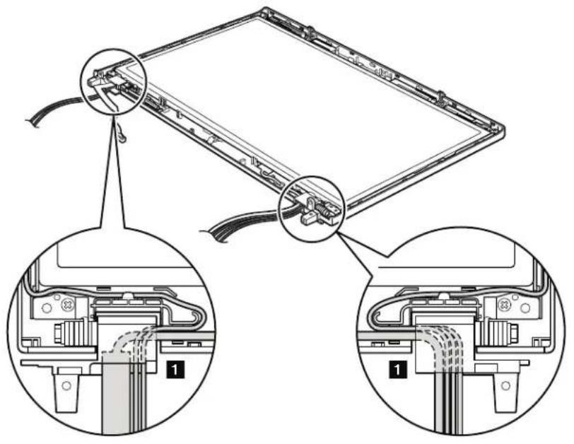
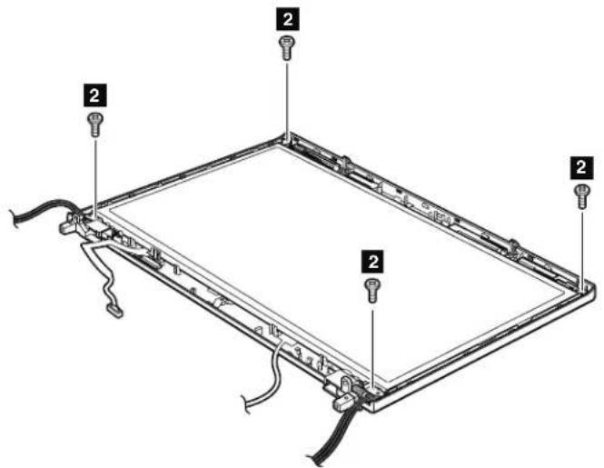
Table40. RemovalstepsofLCDcable,cameracable,LCDpanel,andhinges(continued)
| StepScrew的数量(M) | 5x6mm,wafer-head,nylon-coated(4)Black0.392 | Nm | (4.0kgfcm) |
Wheninstalling:WhenattachingtheLCDpaneltothecover,presstheleftand rightedgescoveredwithmetalgentlywithyourfingers.DONOTpressthe surfaceofthepanelorapplyanyexcessiveforcetothepanel.
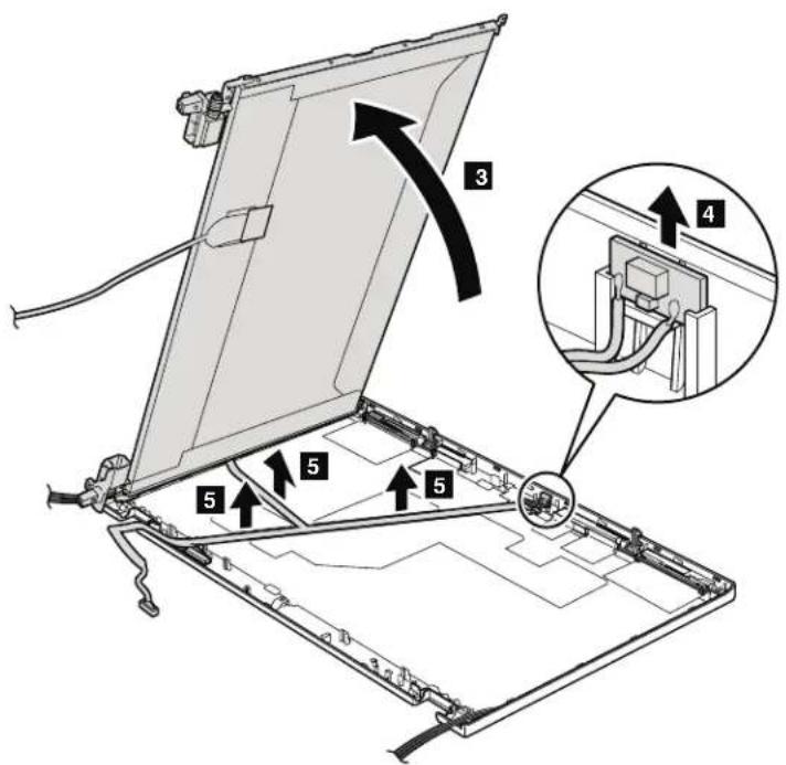
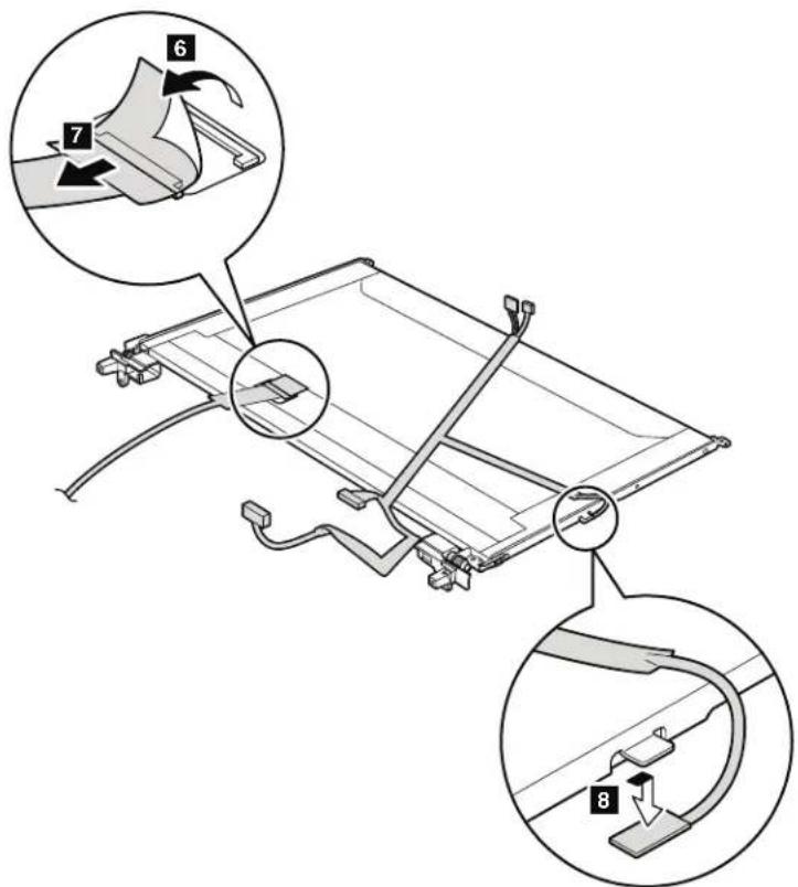
Table40. RemovalstepsofLCDcable,cameracable,LCDpanel,andhinges(continued)
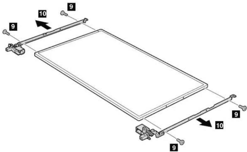
Wheninstalling: MakesurethattheLCDcableconnectorisattachedfirmly.
| StepScrew(color)ColorTorque | ||
| M2×3mm,wafer-head,nylon-coated(4)Silver0.181Nm | (1.85kgfcm) |
2050AntennakitandLCDrearcoverassembly
Foraccess,removetheseFRUsinorder:
"1010Batterypack"onpage87
"030D1MMslotcover"onpage89
050Harddiskdriveslotcover,harddiskdrive(HDD)andHDDrubberrails orSolidstatedrive(SSD)andstorageconverter"onpage91
"060Keyboard"onpage93
1080PCIExpressMiniCardforwirelessLAN"onpage98
"1090PCIExpressMiniCardforwirelessWAN"onpage101
"100Keyboardbezelassembly"onpage103
"170LCDunit"onpage117
"2010LCDbezelassembly" onpage129
2040LCDcable,cameracable,LCDpanel,andhinges"onpage132
Table41.RemovalstepsofantennakitandLCDrearcoverassembly
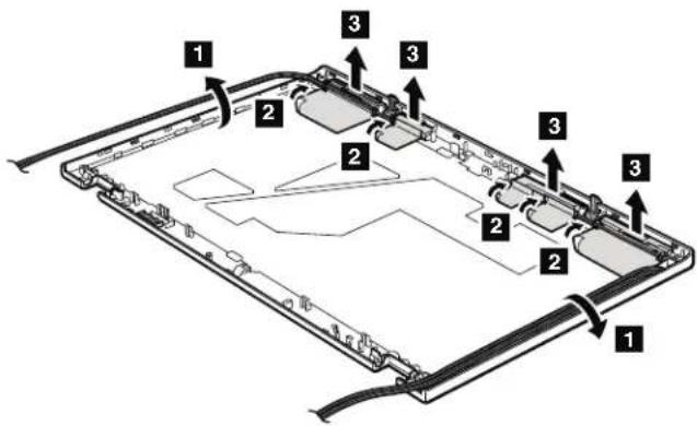
Table41. RemovalstepsofantennakitandLCDrearcoverassembly(continued)
Cablerouting: When you install the antennakit, routethecablessshown in the figures below. As your routethecables, makes sure that they are not subjected to any tension. Tension could cause the cablestobed damaged by the cable guides, or wiretobebroken.
a:WirelessWANantenna.AUX(blue)
:WirelessLANantenna,AUX(black)
c:WirelessLANantenna,3rd(white)
d:WirelessLANantenna,MAIN(gray)
e:WirelessWANMAIN(orange)
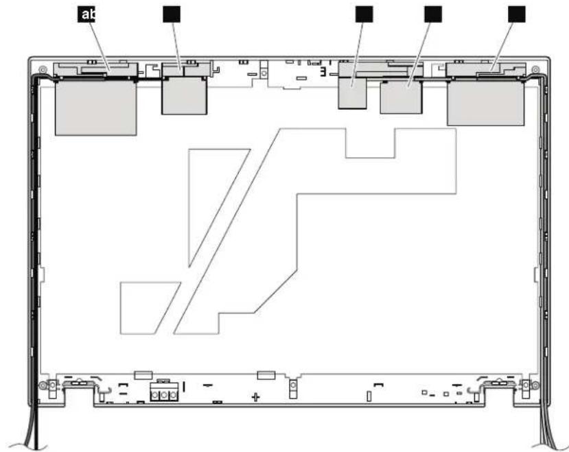
Locations
This chapter presents the location of ThinkPad T510, T510i, and W510 features and hardware.
Frontview
Statusindicators Note:Forthedescriptionofeachindicator,see"Statusindicators"onpage 73
2 Built-inmicrophone
3 Integratedcamera(forsomemodels)
4 ThinkLight
5 Powerswitch
6 Securitykeyhole
7 RJ-45(Ethernet)connector
Built-instereospeakers
9 SerialUltrabayEnhanceddriveortravelbezel
10 Combaudiojack
11 MediaCardReaderslot
12 ExpressCardslot
13 Fingerprintreader(forsomemodels)
14 Colorsensor(forsomemodels)
15 Touchpadbuttons
16 Touchpad
17 TrackPointbuttons
18 TrackPointpointingstick
19 UltraNav
20 ThinkVantagebutton
21 Volumecontrolbuttons
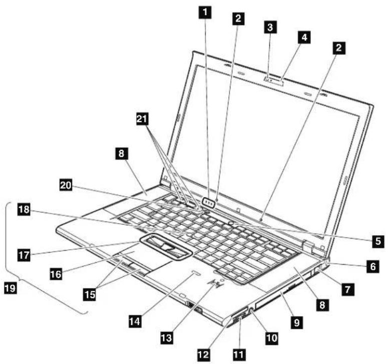
Rearview
1 Statusindicators
Note:Forthedescriptionofeachindicator,see"Statinsindicators"onpage

2 SmartCardslot(forsomemodels)
3 Wireless radioswitch
4 IEEE1394connector
5 USB/eSATAcombocomnector(forsomemodels)
6 Universalserialbus(USB)connectors
7 Externalmonitorconnector
8 DisplayPort
9 ACpowerconnector
10 RJ-11(modem)connector
11 USBconnector
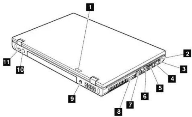
Bottomview
1 Batterypack
2 Batterypacklatch
3 Dockingconnector
4 Solidstatedrive(SSD)orharddiskdrive(HDD)slot
5 DIMMslot(bottom)
6 LCDcoverlatch
7 SerialUltrabayEnhancedlocklatch
8 SerialUltrabayEnhancedejectlatch
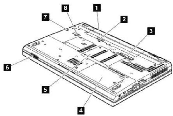
Partlist
This chapter contains following listsof the service parts.
Overall"onpage142
"LCDFRUs"onpage170
"Keyboard"onpage186
"Miscellaneousparts"onpage187
"ACadapters"onpage189
"Powercords"onpage190
"Recoverydiscs"onpage191
Commonservicetools"onpage200
Notes:
EachFRUisavailableforalltypesormodels,unlessspecificitypesormodels arespecified.
- FRUwithspecificmodelsslistedanddescribedasxxU(whereUisanexample ofacountrydesignator)shouldbeusedforallmodelsendinginU.
- FRUwithspecificmodelsslistedanddescribedas3Dx(where3Disan exampleofauniqueconfiguration)shouldbeusedforallofthesemodels, unlessspecificcountryorregiondesignatorisspecified.
- ACRU(customerreplaceableunit)isidentifiedbyasingleasterisk(*)ortwo asterisks**intheCRUIDcolumn.AnNintheCRUIDcolumnmeansthat thepartisnotaCRU.Asingleasterisk*meansthathepartisaSelf-service CRU;twoasterisks**meansthathepartisanOptional-serviceCRU.
ThinkPad Notebooks contain the following types of CRUs:
Self-serviceCRUs
These CRUsunplugorareheldbynomorethantwoscrews.
ExamplesofthesetypesofCRUsincludeanacadapter,apowercord, abattery,andahardiskdrive.OtherSelf-serviceCRUsdepending onproductdesignmayincludeamemory,awirelesscard,akeyboard, andapalmrestwithfingerprintreaderandtouchpad.
Optional-serviceCRUs
These CRUs are isolated parts within the computer that are concealed by an access panel that is typically secured by more than two screws.
Oncetheaccesspanelismoved,thespecificCRUisvisible.
- FRUsmarkedwith OP areavailableasoptions.
Overall
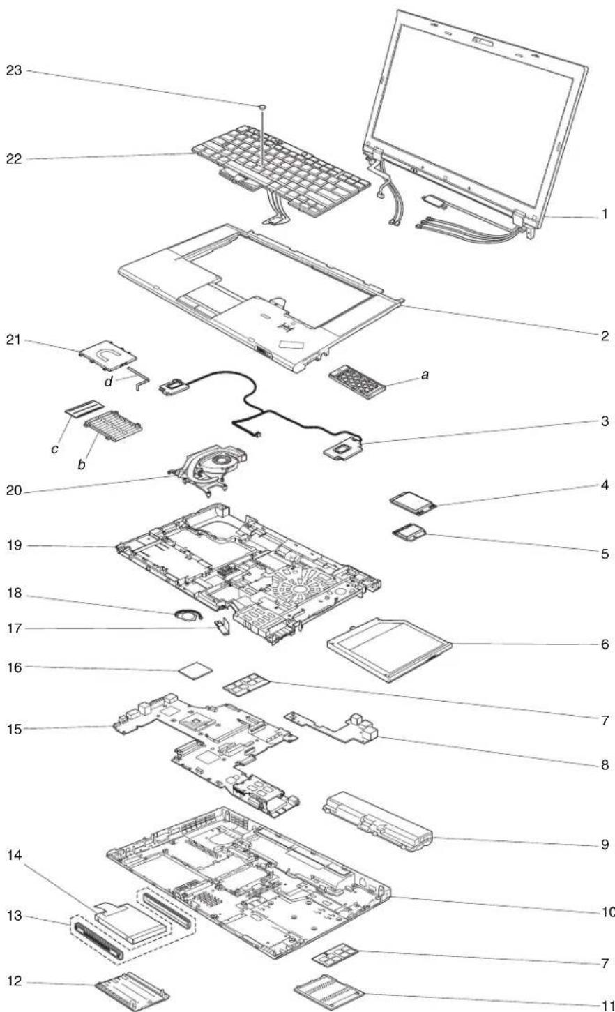
Table42.Partlist-Overall
| No.FRU(Overall)FRU,no.CRU | ID | |
| a - d See "Miscellaneousparts"onpage187. | ||
| 1LCDunit(see"LCLFRUs"onpage170.) | ||
| 2Keyboardbezelassembly, no-FingerprintReader(FPR), no-ColorSensor(CS) for T510·4313-CTO,28x29x·4314-CTO,2Jx,2Kx,2Mx,38x,4Px,5Lx,5Mx·4339-CTO,2Dx·4349-CTO,2Lx,2Qx,2Sx,3Px,48x,49x,4Ax,E2x·4384-CTO·4484-CTO·4873-CTO | 60Y5502N | |
| 2Keyboardbezelassembly,FPR, no-CS, with SmartCard Readerfor T510·4313-CTO·4314-CTO·4339-CTO·4349-CTO,5Kx·4384-CTO·4484-CTO·4873-CTO | 60Y5504N | |
| 2Keyboardbezelassembly,FPR, no-CS, no-SmartCard Readerfor T510·4313-CTO,22x,23x,24x,25x,26x,27x,2Bx,5Dx,5Ex,5Fx·4314-CTO,2Cx,2Dx,2Ex,2Fx,2Gx,2Hx,2Lx,2Nx,2Px,2Qx,2Rx,2Sx,2Tx,2Ux,2Vx,2Xx,2Zx,32x,33x,34x,35x,36x,37x,39x,3Ax,3Bx,3Cx,3Dx,3Ex,3Fx,3Gx,3Hx,3Jx,3Kx,3Lx,3Mx,3Nx,3Px,3Qx,3Rx,3Sx,3Tx,3Ux,3Vx,3Wx,3Xx,3Yx,3Zx,42x,43x,44x,45x,46x,47x,48x,49x,4Ax,4Bx,4Cx,4Dx,4Ex,4Fx,4Gx,4Hx,4Jx,4Kx,4Lx,4Mx,4Nx,4Qx,4Rx,4Sx,4Tx,4Vx,4Wx,5AxBx,5Cx,5Gx,5Hx,5Jx,5Kx,5Nx,5PxA,5PxBx,5RxBx,5Sx,5Tx,5Ux,5Vx,5Wx,5Xx,5Zx,62x,63x,64x,65x,66x,67x,68x,69x,6Ax,6Bx,6Cx,6Dx,6Ex,6Fx,6Gx,6Hx,6Jx,6Kx,6Lx,6Mx,6Nx,6Px,6Qx,6Rx,6Sx,6Tx,6Vx,6Wx,6Xx,6Yx·4339-CTO,27x,28x,29x,2Ax,2Bx,2Cx·4349-CTO,2Ex,2Fx,2Gx,2Hx,2Jx,2Kx,2Nx,2Rx,2Ry,2Tx,2Ux,2Vx,2Xx,2Yx,2Zx,32x,33x,34x,35x,36x,38x,39x,3Ax,3Bx,3Hx,3Jx,3Kx,3Lx,3Mx,3Nx,3Qx,3Rx,3Sx,3Tx,3Ux,3Vx,3Wx,3Xx,3Yx,42x,4Bx,4Cx,4Dx,4Ex,4Fx,4Gx,4Hx,4Jx,4Kx,4Lx,4Mx,4Nx,4PxA,4QxA,5KxA,5ExA,5ExA,5ExA·4384-CTO,2Mx,2Rx,3Ax,3Bx,3Cx,3Dx,3Ex,43x,44x,45x,46x,47x,4Bx·4484-CTO·4873-CTO | 60Y5506N | |
| 2Keyboardbezelassembly, no-FPR, no-CSfor W510·4318-CTO·4319-CTO,25x,27x·4387-CTO·4389-CTO,22x,27x·4391-CTO,22x | 75Y4563N | |
| 2Keyboardbezelassembly, no-FPR, CSfor W510·4318-CTO·4319-CTO,2Cx·4387-CTO·4389-CTO·4391-CTO·4875-CTO·4876-CTO | 60Y5503N | |
| 2Keyboardbezelassembly,FPR,CSforW510·4318-CTO·4319-CTO,2Dx·4387-CTO·4389-CTO,2Px,3Cx·4391-CTO·4875-CTO·4876-CTO | 60Y5505N | |
| 2Keyboardbezelassembly,FPR,no-CSforW510·4318-CTO·4319-CTO,24x·4387-CTO·4389-CTO,2Ax,2Fx,2Nx·4391-CTO·4875-CTO·4876-CTO | 75Y4564N | |
| 2Keyboardbezelassembly,FPR,no-CS,no-SmartCardReaderforW510·4318-CTO·4319-CTO,2Ex,2Fx,2Gx,2Rx,2Tx,2Ux,2Vx,2Wx,2Xx,2Yx,2Zx,32x,34x,3Dx,3Ex,3Fx,3Cx,3Hx,3Jx,3Kx,3Lx,3Mx,3Nx,3Px,3Qx,3Rx,3Sx,3Tx,3Ux,3Vx,3Wx,3Xx,3Yx,3Zx,42x,43x,44x,45x,46x,47x·4387-CTO·4389-CTO,26x,2Cx,2Hx,2Jx,2Kx,2Ux,2Zx,32x,33x,3Dx,3Ex,3Fx·4391-CTO·4875-CTO·4876-CTO | 75Y4565N | |
| 3Speakerassembly60Y5751N | ||
| 3Speakerassembly60Y5752N | ||
| 4IntegratedMobileBroadband(Gobi20003GwithGPS)·4313-CTO·4314-CTO,2Cx,2Dx,2Tx,2Ux,2Vx,2Xx,2Zx,32x,34x,3Ax,3Qx,3Tx,3Ux,3Vx,6Tx,6Ux,6Vx,6Wx,6Xx,6Yx·4318-CTO·4319-CTO,24x,25x,27x,29x,2Dx,2Kx,2Lx,2Qx,34x·4339-CTO·4349-CTO,2Ex,2Fx,2Gx,2Kx,2Mx,2Nx,2Px,2Rx,2Tx,2Ux,2Vx,32x,36x,37x,38x,3Hx,3Kx,5Kx,E2x,E3x,E4x,E5x,E6x·4384-CTO,3Ex·4387-CTO·4389-CTO,29x,2Ax,2Dx,2Fx,2Hx,2Nx,2Px,34x,35x,36x,37x,38x,39x,3Ax,3Bx,3Cx·4391-CTO·4484-CTO·4873-CTO·4875-CTO·4876-CTO | 60Y3183N | |
| No.FR U(Overall)FRUno.CRU | ID | |
| 5Intel®Centrino®Wireless-N1000·4313-CTO,5Dx,5Ex,5Fx·4314-CTO,2Kx,2Mx,38x,39x,3Ex,3Fx,3Gx,3Hx,3Jx,3Mx,3Nx,3Px,4Px,5Lx,5Mx,5Qx,5Rx,5Sx,64x,65x,66x,67x,68x,69x,6Ax,6Bx,6Cx,6Dx,6Ex,6Fx,6Gx,6Hx,6Jx,6Lx,6Nx,6Px,6Qx,6Rx,6Sx,6Tx,6Ux,6Vx,6Wx,6Xx,6Yx·4339-CTO·4349-CTO·4384-CTO,44x,45x,46x,47x·4484-CTO·4873-CTO | 60Y3203N | |
| 5ThinkPad11b/g/nWirelessLANMini-PCIExpressAdapterII·4313-CTO,22x,23x,24x,26x,27x,28x,29x,2Bx·4314-CTO,2Jx,35x,36x,37x,3Wx,3Xx,3Yx,6Kx,6Mx·4318-CTO·4319-CTO,2Gx,2Hx,2Jx,3Dx·4339-CTO,27x,28x,29x,2Ax,2Bx,2Cx·4349-CTO,2Lx,2Qx,2Wx,2Xx,2Yx,3Lx,3Mx,3Nx,48x,4Lx·4384-CTO,2Mx·4387-CTO·4389-CTO,22x,2Jx,2Lx,2Mx,32x·4391-CTO·4484-CTO·4873-CTO·4875-CTO·4876-CTO | 43Y6553N | |
| 5ThinkPad11b/g/nWirelessLANMini-PCIExpressAdapterII·4313-CTO,22x,23x,24x,26x,27x,28x,29x,2Bx·4314-CTO,2Jx,35x,36x,37x,3Wx,3Xx,3Vx,6Kx,6Mx·4318-CTO·4319-CTO,2Gx,2Hx,2Jx,3Dx·4339-CTO,27x,28x,29x,2Ax,2Bx,2Cx·4349-CTO,2Lx,2Qx,2Wx,2Xx,2Yy,3Lx,3Mx,3Nx,48x,4Lx·4384-CTO,2Mx·4387-CTO·4389-CTO,22x,2Jx,2Lx,2Mx,32x·4391-CTO·4484-CTO·4873-CTO·4875-CT0·4876-CTO | 60Y3177N | |
| No.FRU(Overall)FRUUno.CRU | ID | |
| 5IntelCentrinoAdvanced-N6200·4313-CTO,25x·4314-CTO,2Cx,2Dx,2Fx,2Gx,2Hx,2Tx,2Ux,3Kx,3Lx,3Rx,3Zx,42x,43x,44x,46x,47x,48x,49x,4Ax,4Bx,4Cx,4Dx,4Jx,4Kx,4Lx,4Mx,4Tx,4Ux,4Vx,4Wx,53x,54x,55x,56x,5Tx,5Ux,5Vx,5Xx,5Zx,62x,63x·4318-CTO·4319-CTO,25x,27x,29x,2Cx,2Dx,2Lx,2Qx,34x,35x,36x,39x,3Ax,3Ex,3Fx,3Gx·4339-CTO,2Dx·4349-CTO,2Fx,2Gx,2Hx,2Jx,2Kx,2Mx,2Sx,2Zx,32x,34x,3Ax,3Bx,3Px,3Rx,3Sx,3Tx,3Ux,3Xx,3Yx,49x,4Ax,4Ex,4Fx,4Lx,4Nx,4Px,4Qx,5Kx,E2x,E3x,E4x,E5x,E6x·4384-CTO,2Rx,3Ax,3Bx,3Cx,3Dx,3Ex,4Bx·4387-CTO·4389-CTO,23x,27x,29x,2Ax,2Bx,2Nx,2Px,2Tx,33x,36x,37x,3Ax·4391-CTO,22x,23x·4484-CTO·4873-CTO·4875-CTO·4876-CTO | 60Y3231N | |
| 5IntelCentrinoUltimate-N6300·4313-CTO·4314-CTO,2Lx,2Nx,2Px,2Qx,2Rx,2Sx,2Vx,2Zx,32x,33x,34x,3Dx,3Sx,3TxDx,3Sx,3Tx,3Ux,3Vx,5Bx,5Cx,5Gx,5Hx,5Wx,5Yx·4318-CTO·4319-CTO,24x,2Ex,2Fx,2Kx,2Nx,2Px,37x,38x,3Bx,3Cx,3Hx,3Jx,3Kx,3Lx,3MxDx,3Nx,3Px,3Qx,3Rx,3Sx,3Tx,3Yx,3Zx,42x,43x·4339-CTO·4349-CTO,2Nx,2Px,2Rx,2Tx,2Ux,2Vx,33x,35x,36x,37x,38x,3Bx,3Hx,3Jx,3KxDy,42x,4Bx,4Cx,4Hx,5KxDy·4384-CTO,43x·4387-CTO·4389-CTO,24x,26x,2Cx,2Dx,2Fx,2Gx,2Hx,2Sx,34x,35x,38x,39x,3Bx,3Cx,3DxDy,3Ex,3FxDy·4391-CTO·4484-CTO·4873-CTO·4875-CTO·4876-CTO | 60Y3233N | |
| 5IntelCentrinoAdvanced-N+WiMAX6250,WWSKU·4313-CTO·4314-CTO,2Ex,45x,4Ex,4Fx,4Gx,4Hx,4Nx,4Qx,4Rx,4Sx,4Yx,4Zx,52x,57x,58x,59x,5Ax,5Jx,5Kx,5Nx,5PxDy·4318-CTO·4319-CTO,22x,3Ux,3Vx,3Wx,3Xx,44x,45x,46x,47xDy·4339-CTO·4349-CTO,3Ux,3Vx,4Fx,4Gx,4JxDy·4384-CTO·4387-CTO·4389-CTO,25x,3GxDy·4391-CTO·4484-CTO·4873-CTO·4875-CTO·4876-CTO | 60Y3195N | |
| No.FRU(Overall)FRUno.CRU | ID | |
| 5IntelCentrinoAdvanced-N+WiMAX6250,RussiaSKU·4313-CTO·4314-CTO,3Ax,3Bx,3Cx·4318-CTO·4319-CTO,2Rx,2Tx,2Ux,2Vx,2Wx,2Xx,2Yx,2Zx,32x,33x·4339-CTO·4349-CTO·4384-CTO·4387-CTO·4389-CTO,2Kx,2Ux2Zx·4391-CTO·4484-CTO·4873-CTO·4875-CTO·4876-CTO | 60Y3209N | |
| 6DVD-RAM/RWdrive·4313-CTO,22x,23x,24x,25x,26x,27x,28x,29x,2Bx,5Dx,5Ex,5Fx·4314-CTO,2Cx,2Dx,2Ex,2Fx,2Gx,2Hx,2Jx,2Kx,2Lx,2Mx,2Nx,2Px,2Qx,2Rx,2Sx,2Tx,2Ux,2Vx,2Zx,32x,33x,34x,35x,36x,37x,38x,39x,3Ax,3Bx,3Cx,3Dx,3Ex,3Fx,3Gx,3Hx,3Jx,3Kx,3Lx,3Mx,3Nx,3Px,3Qx,3Rx,3Sx,3Tx,3Ux,3Vx,3Wx,3Xx,3Yx,4Kx,4Lx,4Mx,4Nx,4Px,4Qx,4Rx,4Sx,4Tx,4Ux,4Vx,4Wx,4Xx,4Yx,4Zx,52x,53x,54x,55x,56x,57x,58x,59x,5Ax,5Bx,5Cx,5Gx,5Hx,5Jx,5Kx,5Lx,5Mx,5Nx,5Px,5Qx,5Rx,5Sx,5Tx,5Ux,5Vx,5Wx,5Xx,5Yx,5Zx,62x,63x,64x,65x,66x,67x,68x,69x,6Ax,6Bx,6Cx,6Dx,6Ex,6Fx,6Gx,6Hx,6Jx,6Kx,6Lx,6Mx,6Nx,6Px,6Qx,6Rx,6Sx,6Tx,6Ux,6Vx,6Wx,6Xx,6Yx·4318-CTO·4319-CTO,22x,24x,25x,29x,2Cx,2Dx,2Ex,2Fx,2Gx,2Jx,2Kx,2Lx,2Px,2Qx,2Rx,2Tx,2Ux,2Wx,2Xx,2Yx,34x,35x,36x,37x,38x,39x,3Ax,3Bx,3Cx,3Ex,3Fx,3Gx,3Jx,3Kx,3Lx,3Qx,3Sx,3Tx,3Ux,3Vx,3Wx,3Xx,3Zx,42x,43x,44x,45x,46x,47x·4339-CTO,27x,28x,29x,2Ax,2Bx,2Cx,2Dx·4349-CTO,2Ex,2Fx,2Gx,2Hx,2Jx,2Kx,2Lx,2Mx,2Nx,2Px,2Qx,2Rx,2Sx,2Tx,2Ux,2Vx,2Wx,2Xx,2Yx,2Zx,33x,34x,35x,36x,37x,38x,39x,3Ax,3Bx,3Hx,3Jx,3Kx,3Lx,3Mx,3Nx,3Px,3Qx,3Rx,3Sx,3Tx,3Ux,3Vx,3Wx,3Xx,3Yx,42x,48x,49x,4Ax,4Bx,4Cx,4Dx,4Ex,4Fx,4Gx,4Hx,4Jx,4Kx,4Lx,4Mx,4Nx,4Px,4Qx,5Kx,E2x,E3x,E4x,E5x,E6x·4384-CTO,2Mx,2Rx,3Ax,3Bx,3Cx,3Dx,3Ex,43x,44x,45x,46x,47x,4Bx·4387-CTO·4389-CTO,2Cx,2Fx,2Gx,2Hx,2Jx,2Kx,2Mx,2Nx,2Px,33x,34x,35x,36x,37x,38x,39x,3Ax,3Bx,3Fx,3Gx·4391-CTO,22x·4484-CTO·4873-CTO·4875-CTO·4876-CTO | ||
| 6DVD-RAM/RWdrive •4313-CTO,22x,23x,24x,25x,26x,27x,28x,29x,5Dx,5Ex,5Fx •4314-CTO,2Cx,2Dx,2Fx,2Gx,2Hx,2Jx,2Kx,2Lx,2Mx,2Nx,2Px,2Qx,2Rx,2Sx, 2Tx,2Ux,2Vx,2Xx,2Zx,32x,33x,34x,35x,36x,37x,38x,39x,3Ax,3Bx,3Cx,3Dx,3Ex, 3Fx,3Gx,3Hx,3Jx,3Kx,3Lx,3Mx,3Nx,3Px,3Qx,3Rx,3Sx,3Tx,3Ux,3Vx,3Wx,3Xx, 3Yx,3Zx,42x,43x,44x,45x,46x,47x,48x,49x,4Ax,4Bx,4Cx,4Dx,4Ex,4Fx,4Gx,4Hx, 4Jx,4Kx,4Lx,4Mx,4Nx,4Px,4Qx,4Rx,4Sx,4Tx,4Ux,4Vx,4Wx,4Xx,4Yx,4Zx,52x, 53x,54x,55x,56x,57x,58x,59x,5Ax,5Bx,5Cx,5Gx,5Hx,5Jx,5Kx,5Lx,5Mx,5Nx, 5Px,5Qx,5Rx,5Sx,5Tx,5Ux,5Vx,5Wx,5Xx,5Yx,5Zx,62x,63x,64x,65x,66x,67x, 68x,69x,6Ax,6Bx,6Cx,6Dx,6Ex,6Fx,6Gx,6Hx,6Jx,6Kx,6Lx,6Mx,6Nx,6Px,6Qx, 6Rx,6Sx,6Tx,6Ux,6Vx,6Wx,6Xx,6Yx •4318-CTO •4319-CTO,22x,24x,25x,29x,2Cx,2Dx,2Ex,2Fx,2Gx,2Jx,2Kx,2Lx,2Px,2Qx,2Rx, 2Tx,2Ux,2Wx,2Xx,2Yx,34x,35x,36x,37x,38x,39x,3Ax,3Bx,3Cx,3Ex,3Fx,3Gx,3Jx, 3Kx,3Lx,3Qx,3Rx,3Sx,3Tx,3Ux,3Vx,3Wx,3Xx,3Yx,42x,43x,44x,45x,46x, 47x •4339-CTO,27x,28x,29x,2Ax,2Bx,2Cx,2Dx •4349-CTO,2Ex,2Fx,2Gx,2Hx,2Jx,2Kx,2Lx,2Mx,2Nx,2Px,2Qx,2Rx,2Sx,2Tx,2Ux, 2Vx,2Wx,2Xx,2Yx,2Zx,32x,33x,34x,35x,36x,37x,38x,39x,3Ax,3Bx,3Hx,3Jx,3Kx, 3Lx,3Mx,3Nx,3Px,3Qx,3Rx,3Sx,3Tx,3Ux,3Vx,3Wx,3Xx,3Yx,42x,48x,49x,4Ax, 4Bx,4Cx,4Dx,4Ex,4Fx,4Gx,4Hx,4Jx,4Kx,4Lx,4Mx,4Nx,4Px,4Qx,5Kx,E2x,E3x, E4x,E5x,E6x •4384-CTO,2Mx,2Rx,3Ax,3Bx,3Cx,3Dx,3Ex,43x,44x,45x,46x,47x,4Bx •4387-CTO •4389-CTO,2Cx,2Fx,2Gx,2Hx,2Jx,2Kx,2Mx,2Nx,2Px,33x,34x,35x,36x,37x,38x, 39x,3Ax,3Bx,3Fx,3Gx •4391-CTO,22x •4484-CTO •4873-CTO •4875-CTO •4876-CTO | 45N7455* | |
| 6DVD-RAM/RWdrive •4313-CTO,22x,23x,24x,25x,26x,27x,28x,29x,2Bx,5Dx,5Ex,5Fx •4314-CTO,2Cx,2Dx,2Ex,2Fx,2Gx,2Hx,2Jx,2Kx,2Lx,2Mx,2Nx,2Px,2Qx,2Rx,2Sx,2Tx,2Ux,2Vx,2Zx,32x,33x,34x,35x,36x,37x,38x,39x,3Ax,3Bx,3Cx,3Dx,3Ex,3Fx,3Gx,3Hx,3Jx,3Mx,3Nx,3Px,3Qx,3Rx,3Sx,3Tx,3Ux,3Vx,3Wx,3Xx,3Yx,3Zx,42x,43x,44x,45x,46x,47x,48x,49x,4Ax,4Bx,4Cx,4Dx,4Fx,4Fx,4Gx,4Hx,4Jx,4Kx,4Lx,4Mx,4Nx,4Px,4Qx,4Rx,4Sx,4Tx,4Ux,4Vx,4Wx,4Xx,4Yx,4Zx,52x,53x,54x,55x,56x,57x,58x,59x,5Ax,5Bx,5Cx,5Gx,5Hx,5Jx,5Kx,5Lx,5Mx,5Nx,5Px,5Qx,5Rx,5Sx,5Tx,5Ux,5Vx,5Wx,5Xx,5Yx,5Zx,62x,63x,64x,65x,66x,67x,68x,69x,6Ax,6Bx,6Cx,6Dx,6Ex,6Fx,6Gx,6Hx,6Jx,6Kx,6Lx,6Mx,6Nx,6Px,6Qx,6Rx,6Sx,6Tx,6Ux,6Vx,6Wx,6Xx,6Yx •4318-CTO •4319-CTO,22x,24x,25x,29x,2Cx,2Dx,2Ex,2Fx,2Gx,2Jx,2Kx,2Lx,2Px,2Qx,2Rx,2Tx,2Ux,2Wx,2Yx,2Yx,34x,35x,36x,37x,38x,39x,3Ax,3Bx,3Cx,3Ex,3Fx,3Gx,3Jx,3Kx,3Lx,3Qx,3Rx,3Sx,3Tx,3Ux,3Vx,3Wx,3Xx,3Zx,42x,43x,44x,45x,46x,47x •4339-CTO,27x,28x,29x,2Ax,2Bx,2Cx,2Dx •4349-CTO,2Ex,2Fx,2Gx,2Hx,2Jx,2Kx,2Lx,2Mx,2Nx,2Px,2Qx,2Rx,2Sx,2Tx,2Ux,2Vx,2Wx,2Xx,2Yx,2Zx,33x,34x,35x,36x,37x,38x,39x,3Ax,3Bx,3Hx,3Jx,3Kx,3Lx,3Mx,3Nx,3Px,3Qx,3Rx,3Sx,3Tx,3Ux,3Vx,3Wx,3Xx,3Yx,42x,48x,49x,4Ax,4Bx,4Cx,4Dx,4Ex,4Fx,4Gx,4Hx,4Jx,4Kx,4Lx,4Mx,4Nx,4Px,4Qx,5Kx,E2x,E3x,E4x,E5x,E6x •4384-CTO,2Mx,2Rx,3Ax,3Bx,3Cx,3Dx,3Ex,44x,45x,46x,47x,4Bx •4387-CTO •4389-CTO,2Cx,2Fx,2Gx,2Hx,2Jx,2Kx,2Mx,2Nx,2Px,33x,34x,35x,36x,37x,38x,39x,3Ax,3Bx,3Fx,3Gx •4391-CTO,22x •4484-CTO •4873-CTO •4875-CTO •4876-CTO | 45N7461* | |
| 6Blu-raycombodrive •4313-CTO •4314-CTO •4318-CTO •4319-CTO,2Zx,3Mx •4339-CTO •4349-CTO •4384-CTO •4387-CTO •4389-CTO,2Ux,3Dx •4391-CTO •4484-CTO •4873-CTO •4875-CTO •4876-CTO | 42T2617* | |
| 6Blu-rayburner·4313-CTO·4314-CTO·4318-CTO·4319-CTO·4339-CTO·4349-CTO·4384-CTO·4387-CTO·4389-CTO·4873-CTO·4875-CTO·4876-CTO·4484-CTO·4391-CTO | 45N7463* | |
| 6RA IDadapter·4318-CTO·4319-CTO,27x,2Hx,2Nx,2Vx,32x,33x,3Dx,3Hx,3Nx,3Px·4387-CTO·4389-CTO,24x,26x,2Dx,2Lx,2Sx,2Tx,2Zx,32x,3Cx,3Ex·4391-CTO,23x·4875-CTO·4876-CTO | 60Y5513* | |
| 6Travelcover60Y5512* | ||
| 71-GBDDR3-1066SDRAMSO-DIMM(PC3-8500)card·4313-CTO·4314-CTO,2Cx,39x,3Ax,3Bx,3Cx,3Hx,5Tx,5Ux,5Vx,5Wx,6Cx,6Dx,6Sx·4318-CTO·4319-CTO,2Fx,2Gx,2Jx,2Kx,2Lx,2Px,2Vx,32x,35x,36x,37x,38x,3Hx,3Nx,44x·4339-CTO·4349-CTO,2Lx,4Lx,4Mx,4Nx,5Kx,E3x,E6x·4384-CTO,3Ax,3Bx,3Cx,47x,4Bx·4387-CTO·4389-CTO,2Ax,2Bx,2Nx,2Ux,3Dx·4391-CTO·4484-CTO·4873-CTO·4875-CTO·4876-CTO | 55Y3712** | |
| No.FRU(Overall)FRU.No.CRU | ID | |
| 72-GBDDR3-1066SDRAMSO-DIMM(PC3-8500)card·4313-CTO,22x,23x,24x,25x,26x,27x,28x,29x,2Bx,5Dx,5Ex,5Fx·4314-CTO,2Cx,2Dx,2Ex,2Fx,2Gx,2Hx,2Jx,2Kx,2Lx,2Mx,2Nx,2Px,2Qx,2Rx,2Sx,2Tx,2Ux,2Vx,2Xx,2Zx,33x,34x,35x,36x,37x,38x,39x,3Ax,3Bx,3Cx,3Ex,3Fx,3Gx,3Hx,3Jx,3Kx,3Lx,3Mx,3Nx,3Px,3Qx,3Rx,3Sx,3Tx,3Ux,3Vx,3Wx,3Xx,3Yx,3Zx,42x,43x,44x,45x,46x,47x,48x,49x,4Ax,4Bx,4Cx,4Dx,4Ex,4Fx,4Gx,4Hx,4Jx,4Kx,4Lx,4Mx,4Nx,4Px,4Qx,4Rx,4Sx,4Tx,4Ux,4Vx,4Wx,4Xx,4Yx,4Zx,52x,53x,54x,55x,56x,57x,58x,59x,5Ax,5Nx,5Px,5Qx,5Rx,5Sx,5Tx,5Ux,5Vx,5Wx,5Xx,5Yx,5Zx,62x,63x,64x,65x,66x,67x,68x,69x,6Ax,6Bx,6Cx,6Dx,6Ex,6Fx,6Gx,6Hx,6Jx,6Kx,6Lx,6Mx,6Nx,6Px,6Qx,6Rx,6Sx,6Tx,6Ux,6Vx,6Wx,6Xx,6Yx·4318-CTO·4319-CTO,22x,24x,25x,27x,29x,2Cx,2Dx,2Ex,2Fx,2Gx,2Hx,2Jx,2Kx,2Lx,2Nx,2Px,2Qx,2Rx,2Tx,2Ux,2Vx,2Wx,2Xx,2Yx,2Zx,32x,33x,34x,35x,36x,37x,38x,39x,3Ax,3Bx,3Cx,3Lx,3Mx,3Kx,3Lx,3Mx,3Nx,3Tx,3Ux,3Vx,3Wx,3Xx,3Zx,42x,43x,44x,45x,46x,47x·4339-CTO,27x,28x,29x,2Ax,2Bx,2Cx,2Dx·4349-CTO,2Ex,2Fx,2Gx,2Hx,2Kx,2Lx,2Mx,2Nx,2Px,2Qx,2Rx,2Sx,2Tx,2Ux,2Vx,2Wx,2Zx,32x,33x,34x,35x,36x,37x,38x,39x,3Ax,3Bx,3Hx,3Jx,3Kx,3Lx,3Mx,3Nx,3Px,3Qx,3Rx,3Sx,3Tx,3Ux,3Vx,3Wx,3Xx,3Yx,42x,48x,49x,4Ax,4Bx,4Cx,4Dx,4Ex,4Fx,4Gx,4Hx,4Jx,4Kx,4Lx,4Mx,4Nx,4Px,4Qx,5Kx,E2x,E3x,E4x,E5x,E6x·4384-CTO,2Mx,2Rx,3Ax,3Bx,3Cx,3Dx,3Ex,43x,44x,45x,46x,47x,4Bx·4387-CTO·4389-CTO,22x,23x,25x,27x,29x,2Ax,2Bx,2Cx,2Dx,2Fx,2Gx,2Hx,2Jx,2Kx,2Lx,2Mx,2Nx,2Px,2Sx,2Tx,2Ux,2Zx,32x,33x,34x,35x,36x,37x,38x,39x,3Ax,3Bx,3Cx,3Dx,3Ex,3Fx,3Gx·4391-CTO,22x,23x·4484-CTO·4873-CTO·4875-CTO·4876-CTO | 55Y3713** | |
| 74-GBDDR3-1333SDRAMSO-DIMM(PC3-10600)card·4313-CTO·4314-CTO,3Dx,5Bx,5Cx,5Gx,5Hx,5Jx,5Kx,5Lx,5Mx·4318-CTO·4319-CTO·4339-CTO·4349-CTO,21x·4384-CTO·4387-CTO·4389-CTO,24x,26x·4391-CTO·4484-CTO·4873-CTO·4875-CTO·4876-CTO | 55Y3717** | |
| 8US Bsubcard,black·4313-CTO,24x,25x·4314-CTO,35x,36x,38x,39x,3Ax,3Hx,3Kx,6Px·4339-CTO,27x,28x·4349-CTO,2Vx,2Wx·4384-CTO·4484-CTO·4873-CTO | 63Y2124N | |
| No.FRU(Overall)FRUno.CRU | ID | |
| 8USBSubcard,yellow•4313-CTO,22x,23x,26x,27x,28x,29x,2Bx,5Dx,5Ex,5Fx•4314-CTO,2Cx,2Dx,2Ex,2Fx,2Gx,2Hx,2Jx,2Kx,2Lx,2Mx,2Nx,2Px,2Qx,2Rx,2Sx,2Tx,2Ux,2Vx,2Xx,2Zx,32x,33x,34x,37x,3Bx,3Cx,3Dx,3Ex,3Fx,3Gx,3Jx,3Lx,3Mx,3Nx,3Px,3Qx,3Rx,3Sx,3Tx,3Ux,3Vx,3Wx,3Xx,3Yx,3Zx,42x,43x,44x,45x,46x,47x,48x,49x,4Ax,4Bx,4Cx,4Dx,4Ex,4Fx,4Gx,4Hx,4Jx,4Kx,4Lx,4Mx,4Nx,4Px,4Qx,4Rx,4Sx,4Tx,4Ux,4Vx,4Wx,4Xx,4Yx,4Zx,52x,53x,54x,55x,56x,57x,58x,59x,5Ax,5Bx,5Cx,5Gx,5Hx,5Jx,5Kx,5Lx,5Mx,5Nx,5Px,5Qx,5Rx,5Sx,5Tx,5Ux,5Vx,5Wx,5Xx,5Yx,5Zx,62x,63x,64x,65x,66x,67x,68x,69x,6Ax,6Bx,6Cx,6Dx,6Ex,6Fx,6Gx,6Hx,6Jx,6Kx,6Lx,6Mx,6Nx,6Rx,6Sx,6Tx,6Ux,6Vx,6Wx,6Xx,6Yx•4318-all•4319-all•4339-CTO,29x,2Ax,2Bx,2Cx,2Dx•4349-CTO,2Ex,2Fx,2Gx,2Hx,2Jx,2Kx,2Lx,2Mx,2Nx,2Px,2Qx,2Rx,2Sx,2Tx,2Ux,2Xx,2Yx,2Zx,32x,33x,34x,35x,36x,37x,38x,39x,3Ax,3Bx,3Hx,3Kx,3Lx,3Mx,3Nx,3Px,3Qx,3Rx,3Sx,3Tx,3Ux,3Vx,3Wx,3Xx,3Yx,42x,48x,49x,4Ax,4Bx,4Cx,4Dx,4Ex,4Fx,4Gx,4Hx,4Jx,4Kx,4Lx,4Mx,4Nx,4Px,4Qx,5Kx,E2x,E3x,E4x,E5x,E6x•4384-CTO,2Mx,2Rx,3Ax,3Bx,3Cx,3Dx,3Ex,43x,44x,45x,46x,47x,4Bx•4387-all•4389-all•4391-all•4484-CTO•4873-CTO•4875-all•4876-all | 63Y2125N | |
| 9Batterypack,Li-ion(4cell)25•4313-CTO•4314-CTO•4339-CTO•4349-CTO•4384-CTO•4484-CTO•4873-CTO | 42T4763* | |
| 9Batterypack,Li-ion(4cell)25•4313-CTO•4314-CTO•4339-CTO•4349-CTO•4384-CTO•4484-CTO•4873-CTO | 42T4765* | |
| 9Batterypack,Li-ion(6cell)55+·4313-CTO,22x,24x,25x,26x,27x,28x,29x,2Bx,5Dx,5Ex,5Fx·4314-CTO,2Cx,2Ex,2Fx,2Gx,2Kx,2Lx,2Mx,2Nx,2Qx,2Rx,2Tx,2Ux,2Vx,2Xx,32x,33x,35x,36x,37x,38x,39x,3Ax,3Bx,3Cx,3Dx,3Fx,3Gx,3Hx,3Jx,3Kx,3Lx,3Mx,3Nx,3Px,3Sx,3Tx,3Vx,3Xy,3Yx,3Zx,42x,43x,44x,45x,46x,47x,48x,49x,4Ax,4Bx,4Cx,4Dx,4Fx,4Gx,4Hx,4Ix,4Mx,4Nx,4Px,4Qx,4Rx,4Sx,4Tx,4Ux,4Vx,4Wx,4Xx,4Yx,4Zx,52x,53x,54x,55x,56x,57x,58x,59x,5Ax,5Bx,5Cx,5Gx,5Hx,5Jx,5Kx,5Lx,5Mx,5Nx,5Px,5Qx,5Rx,5Sx,5Tx,5Ux,5Vx,5Wx,5Xy,5Zx,62x,63x,64x,65x,66x,67x,68x,69x,6Ax,6Bx,6Cx,6Dx,6Ex,6Fx,6Hx,6Kx,6Lx,6Mx,6Nx,6Px,6Qx,6Rx,6Sx,6Tx,6Ux,6Wx,6Xx·4318-CTO·4319-CTO,29x,2Cx,2Dx,2Ex,2Fx,2Gx,2Hx,2Jx,2Kx,2Lx,2Nx,2Px,2Qx,2Rx,2Vx,2Wx,2Yx,34x,35x,36x,37x,38x,39x,3Ax,3Bx,3Fx,3Gx,3Hx,3Jx,3Kx,3Lx,3Mx,3Nx,3Px,3Qx,3Rx,3Sx,3Tx,3Ux,3Vx,3Wx,3Yx,3Zx,42x,44x,46x·4339-CTO,27x,28x,29x,2Ax,2Bx,2Cx,2Dx·4349-CTO,2Ex,2Fx,2Gx,2Hx,2Jx,2Kx,2Lx,2Mx,2Nx,2Px,2Qx,2Sx,2Tx,2Vx,2Wx,2Xx,2Yx,2Zx,32x,34x,35x,36x,37x,3Bx,3Hx,3Jx,3Kx,3Lx,3Mx,3Nx,3Px,3Qx,3Rx,3Sx,3Tx,3Ux,3Wx,3Xy,3Yx,42x,48x,49x,4Ax,4Bx,4Cx,4Dx,4Fx,4Gx,4Hx,4Ix,4Mx,4Nx,4Px,4Qx,5Kx,E2x,E4x,E5x,E6x·4384-CTO,2Mx,3Ax,3Bx,3Cx,3Dx,3Ex,43x,44x,45x,46x,47x,4Bx·4387-CTO·4389-CTO,22x,23x,25x,27x,2Ax,2Bx,2Dx,2Fx,2Gx,2Hx,2Jx,2Kx,2Lx,2Mx,2Nx,2Px,2Sx,2Tx,2Zx,33x,34x,35x,39x,3Ax,3Bx,3Gx | 42T4791* | |
| 9Batterypack,Li-ion(6cell)55+·4313-CTO,22x,24x,25x,26x,27x,28x,29x,2Bx,5Dx,5Ex,5Fx·4314-CTO,2Cx,2Ex,2Fx,2Gx,2Kx,2Lx,2Mx2Qx,2Rx,2Tx,2Ux,2Vx,2Xx,32x,33x,35x,36x,37x,38x,39x,3Ax,3Bx,3Cx,3Dx,3Fx,3Gx,3Hx,3Jx,3Kx,3Lx,3Mx,3Nx,3Px.3Sx,3Tx,3Ux,3Vx,3Xy,3Zx,42x,44x,46x·4391-CTO,22x,23x·4484-CTO·4873-CTO·4875-CTO·4876-CTO | 42T4793* | |
| 9Batterypack,Li-ion(6cell)55+·4313-CTO,29x,2Cx,2Dx,2Ex,2Fx,2Gx,2Hx,2Jx,2Kx,2Lx,2Nx,2Px,2Qx,2Rx,2Tx,2Vx,2Xx,32x,33x,35x,36x,37x,38x,39x,3Ax,3Bx,3Cx,3Dx,3Fx,3Gx,3Hx,3Jx,3Kx,3Lx,3Mx,3Nx,3Px,3Sx,3Tx,3Ux,3Vx,3Xy,3Zx,42x,44x,45x,46x·4391-CTO,29x,2Cx,2Dx,2Ex,2Fx,2Gx,2Hx,2Jx,2Kx,2Lx,2Nx,2Px,2Qx,2Rx,2Vx,2Wx,2Yx,34x,35x,36x,37x,3Ax,3Bx,3Fx,3Gx,3Hx,3Jx,3Kx,3Lx,3Mx,3Nx,3Px,3Qx,3Rx,3Sx,3Tx,3Ux,3Wx,3Xy,3Zx,42x,44x,45x·4391-CTO,29x,2Cx,2Dx,2Ex,2Fx,2Gx,2Hx,2Jx,2Kx,2Lx,2Nx,2Px,2Qx,2Rx,2Vx,2Wx,2Yx,34x,35x,36x,37x,3Ax,3Bx,3Fy,4Qx,4Qy,5Kx,E2x,E4x,E5x,E6x·4384-CTO,2Mx,3Ax,3Bx,3Cx,3Dx,3Ex,43x,44x,45x,46x,47x,4Bx·4387-CTO·4873-CTO·4875-CTO·4876-CTO | ||
| 9Batterypack,Li-ion(6cell)55+·4313-CTO,22x,24x,25x,26x,27x,28x,29x,2Bx,5Dx,5Ex,5Fx·4314-CTO,2Cx,2Ex,2Fx,2Gx,2Kx,2Lx,2Mx,2Nx,2Qx,2Rx,2Tx,2Ux,2Vx,2Xx,32x,33x,35x,36x,37x,38x,39x,3Ax,3Bx,3Cx,3Dx,3Fx,3Gx,3Hx,3Jx,3Kx,3Lx,3Mx,3Nx,3Px,3Sx,3Tx,3Ux,3Vx,3Xy,3Yx,3Zx,42x,43x,44x,45x,46x,47x,48x,49x,4Ax,4Bx,4Cx,4Dx,4Ex,4Gx,4Hx,4Ix,4Kx,4Iy,4Lx,4Mx,4Nx,4Px,4Qx,4Rx,4Sx,4Tx,4Ux,4Vx,4Wx,4Xy,4Yx,4Zx,52x,53x,54x,55x,56x,57x,58x,59x,5Ax,5Bx,5Cx,5Gx,5Hx,5Jx,5Kx,5Lx,5Mx,5Nx,5Px,5Qx,5Rx,5Sx,5Tx,5Ux,5Vx,5Wx,5Xy,5Zx,62x,63x,64x,65x,66x,67x,68x,69x,6Ax,6Bx,6Cx,6Dx,6Ex,6Fx,6Hx,6Kx,6Lx,6Mx,6Nx,6Px,6Qx,6Rx,6Sx,6Tx,6Ux,6Wx,6Xx·4318-CTO·4319-CTO,29x,2Cx,2Dx,2Ex,2Fx,2Gx,2Hx,2Jx,2Kx,2Lx,2Nx,2Px,2Qx,2Rx,2Vx,2Wx,2Yx,34x,35x,36x,37x,38x,39x,3Ax,3Bx,3Fx,3Cx,3Hx,3Jx,3Kx,3Lx,3Mx,3Nx,3Px,3Qx,3Rx,3Sx,3Tx,3Ux,3Vx,3Wx,3Yx,3Zx,42x,44x,46x·4339-CTO,27x,28x,29x,2Ax,2Bx,2Cx,2Dx·4349-CTO,2Ex,2Fx,2Gx,2Hx,2Jx,2Kx,2Lx,2Mx,2Nx,2Px,2Qx,2Sx,2Tx,2Vx,2Wx,2Xx,2Yx,2Zx,32x,34x,35x,36x,37x,3Bx,3Hx,3Jx,3Kx,3Lx,3Mx,3Nx,3Px,3Sx,3Tx,3Ux,3Vx,3Wx,3Xy,3Yx,42x,48x,49x,4Ax,4Bx,4Hx,4Ix,4Lx,4Mx,4Nx,4Px,4Qx,5Kx,E2x,E4x,E5x,E6x·4384-CTO,2Mx,3Ax,3Bx,3Cx,3Dx,3Ex,43x,44x,45x,46x,47x,4Bx·4387-CTO·4389-CTO,22x,23x,25x,27x,2Ax,2Bx,2Dx,2Fx,2Gx,2Hx,2Jx,2Kx,2Lx,2Mx,2Nx,2Px,2Sx,2Tx,2Zx,33x,34x,35x,39x,3Ax,3Bx,3Gx·4391-CTO,22x,23x·4484-CTO·4873-CTO·4875-CTO·4876-CTO | 42T4795* | |
| 9Batterypack,Li-ion(6cell)55+·4313-CTO,22x,24x,25x,26x,27x,28x,29x,2Bx,5Dx,5Ex,5Fx·4314-CTO,2Cx,2Ex,2Fx,2Gx,2Kx,2Lx,2Mx2Nx,2Qx,2Tx,2Ux,2Vx,2Xx,32x,33x,35x,36x,37x,38x,39x,3Ax,3Bx,3Cx,3Dx,3Fx,3Gx,3Hx,3Jx,3Kx,3Lx,3Mx,3Nx,3Px,3Sx,3Tx,T3Ux,3Vx,3Zx,42x,43x,44x,45x,46x,47x,4Bx·4384-CTO·4873-CTO·4875-CTO·4876-CTO | 42T4797* | |
| 9Batterypack,Li-ion(6cell)55+·4313-CTO,22x,24x,25x,26x,27x,28x,29x,2Bx,5Dx,5Ex,5Fx·4314-CTO,2Cx,2Ex,2Fx,2Gx,2Kx,2Lx,2Mn2Nx,2Qx,2Tx,2Tx,2Vx,2Xx,32x,33x,35x,36x,37x,38x,39x,3Ax,3Bx,3Cx,3Dx,3Fx,3Gx,3Hx,3Jx,3Kx,3Lx,3Mx,3Nx,3Px,3Sx,3Tx,3Ux,3Vy,3Xy,3Zx,42x,44x,45x,46x·4339-CTO,27x,28x,29x,2Ax,2Bx,2Cx,2Dx·4349-CTO,2Ex,2Fx,2Gx,2Hx,2Jx,2Kx,2Lx,2Mx2Nx,2Px,2Qx,2Sx,2Tx,2Vx,2Wx,2Xy,2Yx,2Zx,34x,35x,36x,37x,3Bx,3Hx,3Jx,3Kx,3Lx,3Mx,3Nx,3Px,3Sx,3Tx,T3Ux,3Vx,3Xy,3Xy,42x,48x,49x,4Ax,4Bx,4Cx,4Dx,4Ex,4Fx,4Gx,4Hx,4Iy,4Lx,4Mx,4Nx,4Px,4Qx,5Kx,E2x,E4x,E5x,E6x·4384-CTO,2Mx,3Ax,3Bx,3Cx,3Dx,3Ex,43x,44x,45x,46x,47x,4Bx·4387-CTO· 4389-CTO,22x,23x,25x,27x,2Ax,2Bx,2Dx,2Fx,2Gx,2Hx,2Jx,2Kx,2Lx,2Mx,2Nx,2Px,2Sx,2Tx,2Zx,33x,34x,35x,39x,3Ax,A3Bx,3Gx·4391-CTO,22x,23x·4484-CTO·4873-CTO·4875-CTO·4876-CTO | ||
| 9Batterypack,Li-ion(6cell)55+·4313-CTO·4314-CTO·4339-CTO·4349-CTO·4384-CTO·4484-CTO·4873-CTO | 42T4817* | |
| 9Batterypack,Li-ion(6cell)55+·4313-CTO·4314-CTO·4339-CTO·4349-CTO·4384-CTO·4484-CTO·4873-CTO | 42T4819* | |
| 9Batterypack,Li-ion(9cell)55++·4313-CTO,23x·4314-CTO,2Dx,2Hx,2Jx,2Px,2Sx,2Zx,34x,3Ex,3Qx,3Rx,3Wx,6Gx,6Jx,6Vx,6Yx·4318-CTO·4319-CTO,22x,24x,25x,27x,2Tx,2Ux,2Xx,2Zx,32x,33x,3Cx,3Dx,3Ex,3Xx,43x,45x,47x·4339-CTO·4349-CTO,2Rx,2Ux,33x,38x,39x,3Ax,4Kx,E3x·4384-CTO,2Rx·4387-CTO·4389-CTO,24x,26x,29x,2Cx,2Ux,32x,36x,37x,38x,3Cx,3Dx,3Ex,3Fx·4391-CTO,23x·4484-CTO·4873-CTO·4875-CTO·4876-CTO | 42T4799* | |
| 9Batterypack,Li-ion(9cell)55++·4313-CTO,23x·4314-CTO,2Dx,2Hx,2Jx,2Px,2Sx,2Zx,34x,3Ex,3Qx,3Rx,3Wx,6Gx,6Jx,6Vx,6Yx·4384-CTO,2Rx·4387-CTO·4391-CTO,22x,24x,25x,27x,2Tx,2Ux,2Xx,2Zx,32x,33x,3Cx,3Dx,3Ex,3Xx,43x,45x,47x·4339-CTO·4349-CTO,2Rx,2Ux,33x,38x.39x,3Ax,4Kx,E3x·4384-CTO,2Rx·4387-CTO·4389-CTO,24x,26x,29x,2Cx,2Ux,32x,36x,37x,38x,3Cx,3Dx,3Ex,3Fx·4391-CTO,23x·4484-CTO·4873-CTO·4875-CTO·4876-CTO | 42T4801* | |
| 9Batterypack,Li-ion(9cell)55++·4313-CTO,23x·4314-CTO,2Dx,2Hx,2Jx,2Px,2Sx,2Zx,34x,3Ex,3Qx,3Rx,3Wx,6Gx,6Jx,6Vx,6Yx·4318-CTO·4319-CTO,22x,24x,25x,27x,2Tx,2Ux,2Xx,2Zx,32x,33x,3Cx,3Dx,3Ex,3Xx,43x,45x,47x·4339-CTO·4349-CTO,2Rx,2Ux,33x,38x,39x,3Ax,4Kx,E3x·4384-CTO,2Rx·4387-CTO·4389-CTO,24x,26x,29x,2Cx,2Ux,32x,36x,37x,38x,3Cx,3Dx,3Ex,3Fx·4391-CTO,23x·4484-CTO·4873-CTO·4875-CTO·4876-CTO | 42T4803* | |
| 10Basecoverassembly,UMA·4313-CTO,24x,25x,27x,28x,29x,5Dx·4314-CTO,2Cx,2Ex,2Fx,2Gx,2Kx,2Lx,2Tx,2Ux,35x,36x,38x,39x,3Ax,3Hx,3Kx,3Lx,3Nx,3Px,3Sx,3Xx,3Yx,42x,43x,47x,48x,49x,4Ax,4Bx,4Cx,4Dx,4Ex,4Fx,4Gx,4Hx,4Jx,4Kx,4Lx,4Mx,4Nx,4Px,4Qx,4Rx,4Sx,4Tx,4Ux,4Vx,4Wx,4Xx,4Yx,4Zx,52x,53x,54x,55x,56x,57x,58x,59x,5Ax,5Nx,66x,67x,6Ex,6Kx,6Lx,6Px,6Qx,6Tx,6Wx·4339-CTO,27x,28x,2Ax,2Bx,2Cx·4349-CTO,2Ex,2Fx,2Gx,2Hx,2Jx,2Mx,2Nx,2Vx,2Wx,2Yx,34x,35x,36x,37x,3Bx,3Hx,3Jx,3Kx,3Nx,3Px,3Rx,3Sx,3Xx,3Yx,4Bx,4Cx,4Dx,4Ex,4Jx,4Lx,4Nx,4PxA·4384-CTO,2Mx,3Ax,3Cx,3Dx,3Ex·4484-CTO·4873-CTO | 60Y5497N | |
| 10Basecoverassembly,Discrete·4313-CTO,23x,26x,2Bx,5Ex,5Fx·4314-CTO,2Dx,2Hx,2Jx,2Mx,2Nx,2Px,2Qx,2Rx,2Sx,2Vx,2Zx,32x,33x,34x,37x,3Bx,3Cx,3Dx,3Ex,3Fx,3Gx,3Jx,3Mx,3Qx,3Rx,3Tx,3Ux,3Vx,3Wx,3Zx,44x,45x,46x,5Bx,5Cx,5Gx,5Hx,5Jx,5Kx,5Lx,5Mx,5Px,5Qx,5Rx,5Sx,5Tx,5Ux,5Vx,5Wx,5Xx,5Yx,5Zx,62x,63x,64x,65x,68x,69x,6Ax,6Bx,6Cx,6Dx,6Fx,6Gx,6Hx,6Jx,6Mx,6Nx,6Rx,6Sx,6Ux,6Vx,6Xx,6Yx·4339-CTO,29x,2Dx·4349-CTO,2Kx,2Lx,2Px,2Qx,2Rx,2Sx,2Tx,2Ux,2Xx,2Zx,32x,33x,38x,39x,3Ax,3Lx,3Mx,3Qx,3Tx,3Ux,3Vx,3Wx,42x,48x,49x,4Ax,4Fx,4Gx,4Hx,4Kx,4Mx,E2x,E3x,E5x,E6x·4384-CTO,2Rx,3Bx,43x,44x,45x,46x,47x,4Bx·4484-CTO·4873-CTO | 60Y5498N | |
| 10Basecoverassembly,WS·4318-all·4319-all·4387-all·4389-all·4391-all·4875-all·4876-all | 60Y5499N | |
| 11DIMMSlotcover60Y5501** | ||
| 12Hardiskdrivecover60Y5500** | ||
| 13HDDrumberrails41V9756** | ||
| 14SATAHardiskdrive,160GB,5,400rpm·4313-CTO·4314-CTO,47x,48x,49x,4Ax·4318-CTO·4319-CTO·4339-CTO·4349-CTO,2Yx,3Bx·4384-CTO·4387-CTO·4389-CTO·4391-CTO·4484-CTO·4873-CTO·4875-CTO·4876-CTO | 45N7215** | |
| 14SATAHardiskdrive,160GB,5,400rpm·4313-CTO·4314-CTO,47x,48x,49x,4Ax·4318-CTO·4319-CTO·4339-CTO·4349-CTO,2Yx,3Bx·4384-CTO·4387-CTO·4389-CTO·4391-CTO·4484-CTO·4873-CTO·4875-CTO·4876-CTO | 45N7205** | |
| 14SATAHardiskdrive,250GB,5,400rpm·4313-CTO,22x,24x,25x,26x,27x,28x,29x,2Bx,5Dx·4314-CTO,2Fx,2Hx,35x,36x,37x,38x,3Lx,3Nx,3Px,3Xx,3Yx,3Zx,4Bx,4Cx,4Dx,4Ex,4Fx,4Gx,4Hx,4Jx,4Tx,4Ux,4Vx,4Wx,4Xx,4Zx,52x,5Px,66x,6Px,6Qx,6Rx·4318-CTO·4319-CTO,2Fx,34x,46x·4339-CTO,27x,28x,29x,2Ax,2Bx,2Cx,2Dx·4349-CTO,2Ex,2Vx,2Wx,2Xx,2Zx,32x,34x,35x,36x,37x,3Nx,3Px,3Qx,3Xx,4Px,E2x,E4x,E5x·4384-CTO,3Dx,3Ex·4387-CTO·4389-CTO,2Hx,39x,3Gx·4391-CTO,22x·4484-CTO·4873-CTO·4875-CTO·4876-CTO | 45N7217** | |
Table42.Partlist—Overall(continued)
| No.FRU(Overall)FRUno.CRU | ID | ||
| 14SATAHardiskdrive,250GB,5,400rpm·4313-CTO,22x,24x,25x,26x,27x,28x,29x,2Bx,5Dx·4314-CTO,2Fx,2Hx,35x,36x,37x,38x,3Lx,3Nx,3Px,3Xx,3Yx,3Zx,4Bx,4Cx,4Dx,4Ex,4Fx,4Gx,4Hx,4Jx,4Tx,4Ux,4Vx,4Wx,4Xx,4Zx,52x,5Px,66x,6Px,6Qx,6Rx·4318-CTO·4319-CTO,2Fx,34x,46x·4339-CTO,27x,28x,29x,2Ax,2Bx,2Cx,2Dx·4349-CTO,2Ex,2Vx,2Wx,2Xx,2Zx,32x,34x,35x,36x,37x,3Nx,3Px,3Qx,3Xx,4PxA2x,E4x,E5x·4384-CTO,3Dx,3Ex·4387-CTO·4389-CTO,2Hx,39x,3Gx·4391-CTO,22x·4484-CTO·4873-CTO·4875-CTO·4876-CTO | 45N7207** | ||
| 14SATAHardiskdrive,320GB,5,400rpm·4313-CTO,5Ex,5Fx·4314-CTO,2Kx,2Lx,2Mx,2Qx,2Tx,2Ux,2Vx,32x,39x,3Ax,3Bx,3Fx,3Hx,3Kx,3Mx,3Qx,3Rx,3Sx,3Tx,3Ux,3Vx,42x,43x,44x,45x,46x,4Kx,4Lx,4Mx,4Nx,4Px,4Qx,4Rx,4Sx,53x,54x,55x,56x,57x,58x,59x,5Ax,5Bx,5Cx,5Gx,5Hx,5Jx,5Kx,5Lx,5Mx,5Nx,5Qx,67x,68x,69x,6Ax,6Bx,6Ex,6Fx,6Hx,6Kx,6Mx,6Sx,6Tx,6Ux,6Wx,6Xx·4318-CTO·4319-CTO·4339-CTO·4349-CTO,2Mx,2Nx,2Px,2Sx,3Ax,3Rx,3Sx,3Tx,3Ux,3Vx,3Wx,3Yx,42x,48x,49x,4Bx,4Cx,4Dx,4Ex,4Fx,4Gx,4Lx,4Qx·4384-CTO,3Ax,44x·4387-CTO·4389-CTO,22x,2Dx·4391-CTO,23x·4484-CTO·4873-CTO·4875-CTO·4876-CTO | 45N7219** | ||
| 14SATAHardiskdrive,320GB,5,400rpm·4313-CTO,5Ex,5Fx·4314-CTO,2Kx,2Lx,2Mx,2Qx,2Tx,2Ux,2Vx,32x,39x,3Ax,3Bx,3Fx,3Hx,3Kx,x3Mx,3Qx,3Rx,3Sx,3Tx,3Ux,3Vx,42x,43x,44x,45x,46x,4Kx,4Lx,4Mx,4Nx,4Px,4Qx,4Rx,4Sx,53x,54x,55x,56x,57x,58y,59x,5Ax,5Bx,5Cx,5Gx,5Hx,5Jx,5Kx,5Lx,5Mx,5Nx,5Qx,67x,68x,69x,6Ax,6Bx,6Ex,6Fx,6Hx,6Kx,6Mx,6Sx,6Tx,6Ux,6Wx,6XX·4318-CTO·4319-CTO·4339-CTO·4349-CTO,2Gx,2Mx,2Nx,2Px,2Sx,3Ax,3Rx,3Sx,3Tx,3Ux,3Vx,3Wx,3Yx,42x,48x,49x,4Bx,4Cx,4Dx,4Ex,4Fx,4Gx,4Lx,4Qx·4384-CTO,3Ax,41x·4387-CTO·4389-CTO,22x,2Dx·4391-CTO,23x·4484-CTO·4873-CTO·4875-CTO·4876-CTO | 45N7209** |
Table42.Partlist—Overall(continued)
| No.FRU(Overall)FRUno.CRU | ID | |
| 14SATahardiskdrive,500GB,5,400rpm | 45N7221** | |
| •4313-CTO | ||
| •4314-CTO | ||
| •4318-CTO | ||
| •4319-CTO | ||
| •4339-CTO | ||
| •4349-CTO | ||
| •4384-CTO | ||
| •4387-CTO | ||
| •4389-CTO | ||
| •4391-CTO | ||
| •4484-CTO | ||
| •4873-CTO | ||
| •4875-CTO | ||
| •4876-CTO | ||
| 14SATahardiskdrive,500GB,5,400rpm | 45N7211** | |
| •4313-CTO | ||
| •4314-CTO | ||
| •4318-CTO | ||
| •4319-CTO | ||
| •4339-CTO | ||
| •4349-CTO | ||
| •4384-CTO | ||
| •4873-CTO | ||
| •4875-CTO | ||
| •4876-CTO | ||
| 14SATahardiskdrive,250GB,7,200rpm,FDE | 45N7259** | |
| •4313-CTO | ||
| •4314-CTO,2Px,2Sx,2Zx,34x,6Gx,6Jx,6Vx,6Yx | ||
| •4318-CTO | ||
| •4319-CTO | ||
| •4339-CTO | ||
| •4349-CTO,2Rx,2Ux | ||
| •4384-CTO | ||
| •4387-CTO | ||
| •4389-CTO | ||
| •4391-CTO | ||
| •4484-CTO | ||
| •4873-CTO | ||
| •4875-CTO | ||
| •4867-CTO | ||
| 14SATahardiskdrive,250GB,7,200rpm,FDE·4313-CTO·4314-CTO,2Px,2Sx,2Zx,34x,6Gx,6Jx,6Vx,6Yx·4318-CTO·4319-CTO·4339-CTO·4349-CTO,2Rx,2Ux·4384-CTO·4387-CTO·4389-CTO·4391-CTO·4484-CTO·4873-CTO·4875-CTO·4876-CTO | 45N7279** | |
| 14SATahardiskdrive,320GB,7,200rpm·4313-CTO,23x·4314-CTO,2Cx,2Dx,2Ex,2Gx,3Cx,5Rx,5Sx,5Xx,5Yx,5Zx,62x,63x,64x,65x,6Cx·4318-CTO·4319-CTO,22x,24x,25x,27x,29x,2Cx,2Dx,2Gx,2Jx,2Lx,2Px,2Vx,32x,35x,37x,39x,3Ex,3Fx,3Gx,3Kx,3Lx,3Px,3Qx,3Tx,3Ux,3Xx,3Yx,3Zx,42x,43x,44x,45x,47x·4339-CTO·4349-CTO,2Fx,2Hx,33x,38x,39x,3Hx,3Jx,3Kx,3Lx,3Mx,4Hx,4Kx,4Mx,5Kx,E3x,E6x·4384-CTO,2Rx,3Bx,43x,45x,46x·4387-CTO·4389-CTO,23x,24x,25x,27x,29x,2Ax,2Fx,2Gx,2Hx,2Jx,2Kx,2Lx,2Mx,2Px,2Sx,33x,34x,37x,3Ax,3Dx,3Ex,3Fx·4391-CTO,22x·4484-CTO·4873-CTO·4875-CTO·4876-CTO | 45N7255** | |
| 14SATahardiskdrive,320GB,7,200rpm·4313-CTO,23x·4314-CTO,2Cx,2Dx,2Ex,2Gx,3Cx,5Rx,5Sx,5Xx,5Yx,5Zx,62x,63x,64x,65x,6Cx··4318-CTO·4319-CTO,22x,24x,25x,27x,29x,2Cx,2Dx,2Gx,2Jx,2Lx,2Px,2Vx,32x,35x,37x,39x,3Ex,3Fx,3Gx,3Kx,3Lx,3P×,3Qx,3Tx,3Ux,3Xx,3Yx,3Zx,42x,43x,44x,45x,47x·4339-CTO·4349-CTO,2Fx,2Hx,33x,38x,39x,3Hx,3Jx,3Kx,3Lx,3Mx, 4Hx,4Kx,4Mx,5Kx,E3x,E6x·4384-CTO,2Rx,3Bx,43x,45x,46x·4387-CTO·4389-CTO,23x,24x,25x,27x,29x,2Ax,2Fx,2Gx,2Hx ,2Jx,2Kx,2Lx,2Mx,2Sx,33x,34x,37x,3Ax,3Dx,3Ex,3Fx·4391-CTO,22x·4484-CTO·4873-CTO·4875-CTO·4876-CTO | 45N7275** | |
| 14SATahardiskdrive,500GB,7,200rpm·4313-CTO·4314-CTO,2Jx,2Nx,2Rx,2Xx,33x,3Dx,3Ex,3Gx,3Jx,3Wx,5Ux,5Wx,6Dx,6Lx,6Nx·4318-CTO·4319-CTO,2Kx,2Qx,2Rx,2Tx,2Ux,2Wx,2Yx,2Zx,33x,3Ax,3Bx,3Cx,3Dx,3Hx,3Jx,3Mx,3Nx,3Rx,3Sx,3Vx,3Wx·4339-CTO·4349-CTO,2Jx,2Kx,2Qx,2Tx,4Ax,4Jx·4384-CTO,2Mx,47x,4Bx·4387-CTO·4389-CTO,26x,2Bx,2Cx,2Tx,2Ux,2Zx,32x,35x,36x,38x,3Bx,3Cx·4391-CTO·4484-CTO·4873-CTO·4875-CTO·4876-CTO | 45N7257** | |
| 14SATahardiskdrive,500GB,7,200rpm·4313-CTO·4314-CTO,2Jx,2Nx,2Rx,2Xx,33x,3Dx,3Ex,3Gx,3Jx,3Wx,5Ux,5Wx,6Dx,6Lx,6Nx·4318-CTO·4319-CTO,2Kx,2Qx,2Rx,2Tx,2Ux,2Wx,2Yx,2Zx,33x,3Ax,3Bx,3Cx,3Dx,3Hx,3Jx,3Mx,3Nx,3Rx,3Sx,3Vx,3Wx·4339-CTO·4340-CTO,2Jx,2Kx,2Qx,2Tx,4Ax,4Jx·4384-CTO,2Mx,47x,4Bx·4387-CTO·4389-CTO,26x,2Bx,2Cx,2Tx,2Ux,2Zx,32x,35x,36x,38x.3Bx,3Cx·4391-CTO·4484-CTO·4873-CTO·4875-CTO·4876-CTO | 45N7277** | |
| -1.8"-2.5"storageconverter·4313-CTO·4314-CTO,5Tx,5Vx·4318-CTO·4319-CTO,2Ex,2Hx,2Nx,36x,38x·4339-CTO·4340-CTO,2Lx,4Nx·4384-CTO,3Cx·4387-CTO·4389-CTO·4391-CTO·4484-CTO·4873-CTO·4875-CTO·4876-CTO | 42W7888** | |
| -MicroSATAsolidstatedrive,80GB·4313-CTO·4314-CTO·4318-CTO·4319-CTO·4339-CTO·4349-CTO,4Nx·4384-CTO,3Cx·4387-CTO·4389-CTO·4391-CTO·4484-CTO·4873-CTO·4875-CTO·4876-CTO | 41W0524** | |
| -MicroSATAsolidstatedrive,128GB·4313-CTO·4314-CTO,5Tx,5Vx·4318-CTO·4319-CTO,2Ex,2Hx,2Nx,36x,38x·4339-CTO·4349-CTO,2Lx·4384-CTO·4387-CTO·4389-CTO·4391-CTO·4484-CTO·4873-CTO·4875-CTO·4876-CTO | 45N7953** | |
| -MicroSATAsolidstatedrive,128GB·4313-CTO·4314-CTO,5Tx,5Vx·4318-CTO·4319-CTO,2Ex,2Hx,2Nx,36x,38x·4339-CTO·4349-CTO,2Lx·4381-CTO·4387-CTO·4389-CTO·4391-CTO·4484-CTO·4873-CTO·4875-CTO·4876-CTO | 45N8203** | |
| -MicroSATAsolidstatedrive,160GB | 45N7963** | |
| ·4313-CTO | ||
| ·4314-CTO | ||
| ·4318-CTO | ||
| ·4319-CTO | ||
| ·4339-CTO | ||
| ·4349-CTO | ||
| ·4384-CTO | ||
| ·4387-CTO | ||
| ·4389-CTO | ||
| ·4391-CTO | ||
| ·4484-CTO | ||
| ·4873-CTO | ||
| ·4875-CTO | ||
| ·4876-CTO | ||
| -MicroSATAsolidstatedrive,256GB,FDE | 45N7959** | |
| ·4313-CTO | ||
| ·4314-CTO | ||
| ·4318-CTO | ||
| ·4319-CTO | ||
| ·4339-CTO | ||
| ·4349-CTO | ||
| ·4384-CTO | ||
| ·43B7-CTO | ||
| ·4389-CTO | ||
| ·4391-CTO | ||
| ·4484-CTO | ||
| ·4873-CTO | ||
| ·4875-CTO | ||
| ·4876-CTO | ||
| -MicroSATAsolidstatedrive,256 GB,FDE | 45N8207** | |
| ·4313-CTO | ||
| ·4314-CTO | ||
| ·4318-CTO | ||
| ·4319-CTO | ||
| ·4339-CTO | ||
| ·4349-CTO | ||
| ·4384-CTO | ||
| ·43BT-CTO | ||
| ·4389-CTO | ||
| ·4391-CTO | ||
| ·4484-CTO | ||
| ·4873-CTO | ||
| ·4875-CTO | ||
| ·4876-CTO | ||
| 15SystemboardassemblyforT510,integrated,AMT,TPMfornoUSBpower | 63Y2019N | |
| ·4313-CTO,5Dx | ||
| ·4314-CTO,3Nx,3Px,66x,67x,6Ex,6Kx,6Lx,6Tx,6Wx | ||
| ·4339-CTO | ||
| ·4349-CTO | ||
| ·4384-CTO | ||
| ·4484-CTO | ||
| ·4873-CTO |
Table42.Partlist—Overall(continued)
| No.FR | U(Overall)FRUno.CRU | ID | |
| 15Sy | stemboardassemblyforT510,integrated,AMT,TPM·4313-CTO,22x,27x,28x,29x·4314-CTO,2Cx,2Ex,2Fx,2Gx,2Kx,2Lx,2Tx,2Ux,3Lx,3Sx,3Xx,42x,43x,47x,48x,49x,4Ax,4Bx,4Cx,4Dx,4Ex,4Fx,4Gx,4Hx,4Kx,4Lx,4Mx,4Nx,4Px,4Qx,4Rx,4Sx,4Tx,4Ux,4Vx,4Wx,4Xx,4Yx,4Zx,52x,53x,54x,55x,56x,57x,58x,59x,5Ax,5Nx·4339-CTO,2Ax,2Bx,2Cx·4349-CTO,2Ex,2Fx,2Gx,2Hx,2Jx,2Mx,2Nx,2Yx,34x,35x,36x,37x,3Bx,3Hx,3Jx,3Kx,3Nx,3Px,3Rx,3Sx,3Xx,3Yx,4Bx,4Cx,4Dx,4Ex,4Jx,4Lx,4Nx,4Px,4Qx,5Kx,E4x·4384-CTO,2Mx,3Ax,3Cx,3Dx,3Ex·4484-CTO·4873-CTO | 63Y2020N | |
| 15Sy | stemboardassemblyforT510,discrete,AMT,TPM·4313-CTO,23x,2Bx,5Ex,5Fx·4314-CTO,2Dx,2Hx,2Jx,2Mx,2Nx,2Px,2Qx,2Rx,2Sx,2Vx,2Xx,2Zx,32x,33x,34x,3Mx,3Qx,3Rx,3Tx,3Ux,3Vx,3Wx,3Zx,44x,45x,46x,5Bx,5Cx,5Gx,5Hx,5Jx,5Kx,5Lx,5Mx,5Px,5Qx,5Rx,5Sx,5Tx,5Ux,5Vx,5Wx,5Xx,5Yx,5Zx,62x,63x,64x,65x,68x,69x,6Ax,6Bx,6Cx,6Dx,6Fx,6Gx,6Hx,6Jx,6Mx,6Nx,6Ux,6Vx,6Xx,6Yx·4339-CTO,2Dx·4349-CTO,2Kx,2Lx,2Px,2Qx,2Rx,2Sx,2Tx,2Ux,2Zx,32x,33x,38x,39x,3Ax,3Lx,3Mx,3Qx,3Tx,3Ux,3Vx,3Wx,42x,48x,49x,4Ax,4Fx,4Gx,4Hx,4Kx,4Mx,E2x,E3x,E5x,E6x·4384-CTO,2Rx,3Bx,43x,44x,45x,46x,47x,4Bx·4484-CTO·4873-CTO | 63Y2021N | |
| 15Sy | stemboardassemblyforT510,integrated,AMT,non-TPMfornoUSBpower·4313-CTO·4314-CTO,3Hx,3Kx,6Px,6Qx·4339-CTO·4349-CTO·4384-CTO·4484-CTO·4873-CTO | 63Y2023N | |
| 15Sy | stemboardassemblyforT510,integrated,AMT,non-TPM·4313-CTO,24x,25x·4314-CTO,35x,36x,38x,39x,3Ax·4339-CTO,27x,28x·4349-CTO,2Vx,2Wx·4384-CTO·4484-CTO·4873-CTO | 60Y2024N | |
| 15Sy | stemboardassemblyforT510,discrete,AMT,non-TPM·4313-CTO,26x·4314-CTO,37x,3Bx,3Cx,3Dx,3Ex,3Fx,3Gx,3Jx,6Rx,6Sx·4339-CTO,29x·4349-CTO,2Xx·4384-CTO·4484-CTO·4873-CTO | 63Y2025N |
Table42.Partlist—Overall(continued)
| No.FRU(Overall)FRUUno.CRU | ID | |
| 15SysystemboardassemblyforW510,TPM·4318-CTO·4319-CTO,22x,24x,25x,27x,29x,2Ex,2Hx,2Yx,2Zx,32x,34x,35x,36x,37x,38x,39x,3Ax,3Bx,3Dx,3Ex,3Fx,3Hx,3Jx,3Kx,3Lx,3Px,3Qx,3Rx,3Sx,3Tx,3Ux,3Vx,3Wx,3Xx,3Yx,3Zx,42x,43x,44x,45x,46x,47x·4387-CTO·4389-CTO,23x,24x,25x,26x,27x,29x,2Cx,2Dx,2Gx,2Jx,2Kx,2Lx,2Zx,32x,33x,34x,35x,36x,37x,39x,3Bx,3Dx,3Ex,3Fx,3Gx·4391-CTO,22x·4875-CTO·4876-CTO | 63Y2022N | |
| 15SysystemboardassemblyforW510,non-TPM·4318-CTO·4319-CTO,2Fx,2Hx,2Jx,2Kx,2Nx,2Px,2Qx,2Rx·4387-CTO·4389-CTO,2Nx,2Sx,2Tx·4391-CTO·4875-CTO·4876-CTO | 63Y2026N | |
| 15SysystemboardassemblyforW510,TPM,RAID·4318-CTO·4319-CTO,2Cx,2Dx,2Fx,2Gx,3Cx,3Gx,3Mx,3Nx·4387-CTO·4389-CTO,22x,2Hx,2Mx,38x,3Ax,3Cx·4391-CTO,23x·4875-CTO·4876-CTO | 63Y2119N | |
| 15SysystemboardassemblyforW510,non-TPM,RAID·4318-CTO·4319-CTO,2Gx,2Lx,2Tx,2Ux·4387-CTO·4389-CTO,2Px,2Ux·4391-CTO·4875-CTO·4876-CTO | 63Y2120N | |
| 16CPUassembly,Intel® CoreTM i3-330MProcessor(2.13GHz)·4313-CTO,5Dx,5Ex·4314-CTO,6Yx,5Lx,5Mx,5Qx,5Rx,5Sx,5Tx,5Yx,5Zx,63x,65x,66x,69x,6Bx,6Dx,6Ex,6Gx,6Hx·4339-CTO·4349-CTO·4384-CTO·4484-CTO·4873-CTO | 63Y2174N | |
| 16CPUassembly,IntelCorei3-350MProcessor(2.26GHz)·4313-CTO·4314-CTO,6Wx,6Xx·4339-CTO·4349-CTO·4384-CTO·4484-CTO·4873-CTO | 63Y2175N | |
| No.FRU(Overall)FRU,no.CRU | ID | |
| 16CPUassembly,IntelCorei5-430MProcessor(2.26GHz)·4313-CTO,5Fx·4314-CTO,5Gx,5Hx,5Jx,5Kx,5Nx,5Px,5Vx,5Wx,5Xx,62x,64x,67x,68x,6Ax,6Cx,6Fx,6Jx,6Ux,6Vx·4339-CTO·4349-CTO·4384-CTO·4484-CTO·4873-CTO | 63Y2176N | |
| 16CPUassembly,IntelCorei5-520MProcessor(2.40GHz)·4313-CTO,22x,23x,24x,27x,28x·4314-CTO,2Dx,2Ex,2Fx,2Gx,2Hx,2Kx,2Lx,2Mx,2Qx,2Tx,2Ux,2Vx,32x,35x,38x,39x,3Bx,3Lx,3Sx,3Xx,42x,43x,47x,48x,49x,4Ax,4Bx,4Cx,4Dx,4Ex,4Fx,4Gx,4Hx,4Jx,4Kx,4Lx,4Mx,4Nx,4Px,4Qx,4Rx,4Sx,5Nx,5Px,5Qx,5Xx·4339-CTO,27x,2Ax,2Bx·4349-CTO,2Ex,2Fx,2Gx,2Hx,2Kx,2Mx,2Nx,2Px,2Sx,2Vx,2Yx,35x,3Bx,3Hx,3Nx,3Rx,3Sx,3Xx,3Yx,4Hx,4Jx,4Lx,4Mx,4Nx,4Px,4Qx,E2x,E3x,E4x,E5x,E6x·4384-CTO,2Mx,3Ax,3Bx,3Cx,44x·4484-CTO·4873-CTO | 60Y5731N | |
| 16CPUassembly,IntelCorei5-540MProcessor(2.53GHz)·4313-CTO·4314-CTO,2Cx,2Jx,2Nx,2Rx,2Xx,33x,3Ax,4Tx,4Ux,4Vx,4Xx,4Zx,52x,53x,54x,55x,56x,57x,58x,59x,5Ax,5Rx,5Sx,5Tx,5Yx·4339-CTO·4349-CTO,2Lx,2Qx,2Tx,36x,37x,3Jx,3Kx,3Lx,4Bx,4Cx,4Dx,4Ex,5Kx·4384-CTO,45x,46x·4484-CTO·4873-CTO | 60Y5732N | |
| 16CPUassembly,IntelCorei7-620MProcessor(2.66GHz)·4313-CTO,25x,26x,29x,2Bx·4314-CTO,2Px,2Sx,2Zx,34x,36x,37x,3Cx,3Dx,3Ex,3Mx,3Tx,3Ux,3Vx,3Wx,3Yx,3Zx,44x,45x,46x,5Cx,5Gx,5Hx,5Jx,5Kx,5Lx,5Mx,5Ux,5Vx,5Wx,5Zx·4339-CTO,28x,29x,2Cx,2Dx·4349-CTO,2Jx,2Rx,2Ux,2Wx,2Zx,32x,33x,34x,38x,39x,3Ax,3Mx,3Px,3Qx,3Tx,3Ux,3Vx,3Wx,42x,48x,49x,4Ax,4Fx,4Gx,4Kx·4384-CTO,2Rx,3Dx,3Ex,43x,47x,4Bx·4484-CTO·4873-CTO | 60Y5733N | |
| 16CPUassembly,IntelCorei7-720QMProcessor(1.6GHz)·4318-CTO·4319-CTO,22x,24x,25x,2Hx,2Jx,2Kx,2Vx,36x,3Ex,3Fx,3Hx,3Kx,3Mx,3Px,3Rx,3Tx,3Vx,3Xx,3Zx,42x,43x,44x,46x·4387-CTO·4389-CTO,22x,23x,24x,25x,26x,27x,29x,2Dx,2Fx,2Gx,2Sx,33x,34x,3Dx,3Gx·4391-CTO,22x,23x·4875-CTO·4876-CTO | 63Y2000N | |
| No.FRU(Overall)FRUno.CRU | ID | |
| 16CPuassembly,IntelCorei7-820QMProcessor(1.73GHz)·4318-CTO·4319-CTO,27x,29x,2Cx,2Fx,2Lx,2Nx,2Px,2Qx,2Rx,2Wx,2Yx,33x,34x,37x,38x,39x,3Ax,3Bx,3Gx,3Jx,3Lx,3Nx,3Qx,3Sx,3Ux,3Wx,3Yx,45x,47x·4387-CTO·4389-CTO,2Bx,2Cx,2Hx,2Jx,2Nx,2Tx,2Zx,35x,37x,39x,3Bx,3Ex,3Fx·4391-CTO·4875-CTO·4876-CTO | 63Y2001N | |
| 16CPuassembly,IntelCorei7-920XMProcessor(2.0GHz)·4318-CTO·4319-CTO,2Dx,2Ex,2Gx,2Tx,2Ux,2Xx,2Zx,35x,3Cx,3Dx·4387-CTO·4389-CTO,2Ax,2Kx,2Lx,2Mx,2Px,2Ux,32x,36x,38x,3Ax,3Cx·4391-CTO·4875-CTO·4876-CTO | 63Y2002N | |
| 17BBluetoothdaughtercard(BDC-2.1)·4313-CTO,23x,24x,25x,26x,27x,28x,29x,2Bx,5Dx,5Ex,5Fx·4314-CTO,2Cx,2Dx,2Ex,2Fx,2Gx,2Jx,2Kx,2Lx,2Mx,2Nx,2Px,2Qx,2Rx,2Sx,2Tx,2Ux,2Vx,2Xx,32x,34x,36x,37x,38x,3Ax,3Bx,3Cx,3Dx,3Ex,3Fx,3Gx,3Hx,3Jx,3Kx,3Lx,3Mx,3Nx,3Mx,3Px,3Qx,3Ry,3Ry,3Ry,3Ry,3Ry,3Ry,3Ry,3Ry,3Ry,3Ry,3Ry,3Ry,3Ry,3Ry,3Ry,3Ry,3Ry,3Ry,3Ry,3Ry,3Ry,3Ry,3Ry,3Ry,3Ry,3Rx,3Ry,3Ry,3Ry,3Ry,3Ry,3Ry,3Ry,3Ry,3Ry,3Ry,3Ry,3Ry,3Ry,3Ry,3Ry,3Ry,3Ry,3Ry,3Ry,3Ry,3Ry,3Ry,3Ry,3Ry,3Rx,3Lx,3Mx,3Mx,3Mx,3Mx,3Mx,3Mx,3Mx,3Mx,3Mx,3Mx,3Mx,3Mx,3Mx,3Mx,3Mx,3Mx,3Mx,3Mx,3Mx,3Mx,3Mx,3Mx,3Mx,3Mx,3Mx,3Lx,3Mx,3Mx,3Mx,3Mx,3Mx,3Mx,3Mx,3Mx,3Mx,3Mx,3Mx,3Mx,3Mx,3Mx,3Mx,3Mx,3Mx,3Mx,3Mx,3Mx,3Mx,3Mx,3Mx,3M×,3Ry,3Ry,3Ry,3Ry,3Ry,3Ry,3Ry,3Ry,3Ry,3Ry,3Ry,3Ry,3Ry,3Ry,3Ry,3Ry,3Ry,3Ry,3Ry,3Ry,3Ry,3Ry,3Ry,3Ry,3Rr,3Ry,3Ry,3Ry,3Ry,3Ry,3Ry,3Ry,3Ry,3Ry,3Ry,3Ry,3Ry,3Ry,3Ry,3Ry,3Ry,3Ry,3Ry,3Ry,3Ry,3Ry,3Ry,3Ry,3Ry,3Rz,3Ry,3Ry,3Ry,3Ry,3Ry,3Ry,3Ry,3Ry,3Ry,3Ry,3Ry,3Ry,3Ry,3Ry,3Ry,3Ry,3Ry,3Ry,3Ry,3Ry,3Ry,3Ry,3Ry,3Ry,3Rxy·4318-CTO·4319-CTO,22x,24x,25x,27x,29x,2Cx,2Dx,2Fx,2Gx,2Hx,2Jx,2Kx,2Lx,2Nx,2Px,2Qx,2Rx,2Vx,2Wx,2Xx,2Yx,2Zx,32x,33x,34x,35x,36x,37x,38x,39x,3Ax,3Bx,3Cx,3Dx,3Ex,3Fx,3Gx,3Hx,3Jx,4Vx,4Wx,4Xx,4Yx,4Zx,52x,53x,54x,55x,56x,57x,58x,59x,5Ax,5Bx,5Cx,5Gx,5Hx,5Jx,5Kx,5Lx,5Mx,5Nx,5Px,5Qx,5Rx,5Sx,5Tx,5Ux,5Vx,5Wx,5Xx,5Yx,5Zx,62x,63x,65x,66x,67x,68x,69x,6Ax,6Bx,6Cx,6Dx,6Ex,6Fx,6Gx,6Hx,6Jx,6Kx,6Lx,6Mx,6Nx,6Px,6Qx,6Rx,6Sx,6Tx,6Ux,6Vx,6Wx,6Xx,6Yx·4319-CTO·4319-CTO,22x,24x,25x,27x,29x,2Cx,2Dx,2Fx,2Gx,2Hx,2Jx,2Kx,2Lx,2Nx,2Px,2Qx,2Rx,2Sx,2Tx,2Vx,2Vx,2Wx,2Xy,2Qx,2Rx,2Vx,2Wx,2Xy,2Yx,2Zx,32x,33x,34x,35x,36x,37x,38x,39x,3Ax,3Bx,3Cx,3Dx,3Ex,3Fx,3Gx,3Hx,3Jx,3Kx,3Lx,3Mx,3Nx,3Px,3Qx,3Rx,3Sx,3Tx,3Ux,3Vx,3Wx,3Xy,3Zx,42x,43x,44x,45x,47x·4319-CTO,27x,28x,29x,2Ax,2Bx,2Cx,2Dx·4349-CTO,2Ex,2Fx,2Hx,2Jx,2Lx,2Mx,2Nx,2Px,2Qx,2Rx,2Sx,2Tx,2Ux,2Vx,2Wx,2Xy,2Zx,32x,33x,34x,35x,36x,37x,38x,39x,3Ax,3Bx,3Cx,3Dx,3Ex,3Fx,3Gx,3Hx,3Jx,3Kx,3Hx,3Jx,3Kx,3Lx,3Mx,3Nx,3Px,3Qx,3Rx,3Sx,3Tx,3Ux,3Vx,3Wx,3Xy,3Yx,42x,48x,49x,4Ax,4Bx,4Cx,4Dx,4Ex,4Fx,4Gx,4Hx,4Jx,4Kx,4Lx,4Mx,4Nx,4Px,4Qx,5Kx,E2x,E3x·4384-CTO,2Mx,2Rx,3Ax,3Bx,3Cx,3Dx,3Ex,43x,44x,45x,46x,47x,4Bx·4387-CTO·4389-CTO,22x,23x,24x,25x,26x,27x,29x,2Bx,2Ax,2Cx,2Dx,2Fx,2Gx,2Hx,2Jx,2Kx,2Lx,2Mx,2Nx,2Px,2Sx,2Tx,2Ux,2Zx,32x,33x,34x,35x,36x,37x,38x,39x,3Ax,3Bx,3Cx,3Dx,3Ex,3Fx·4391-CTO,22x,23x·4484-CTO·4873-CTO·4875-CTO·4876-CTO | ||
| 18Backupbattery02K7078* | ||
| 19Magnesiumstructureframe60Y5496N | ||
| 20ThermalmoduleforT510integratedgraphicsmodels •4313-CTO,22x,24x,25x,27x,28x,29x,5Fx •4314-CTO,2Cx,2Dx,2Fx,2Gx,2Jx,2Lx,2Mx,2Ux,2Vx,36x,37x,39x,3Ax,3Bx,3Jx,3Lx,3Mx,3Px,3Sx,3Xx,4y,4x,47x,48x,49x,4Ax,4Bx,4Cx,4Dx,4Ex,4Fx,4Gx,4Hx,4Jx,4Kx,4Lx,4Mx,4Nx,4Px,4Rx,4Sx,4Tx,4Ux,4Vx,4Wx,4Xx,4Yx,4Zx,52x,53x,54x,55x,56x,57x,58x,59x,5Ax,5Nx,66x,67x,6Ex,6Kx,6Lx,6Px,6Qx,6Tx,6Wx •4339-CTO,27x,28x,2Ax,2Bx,2Cx •4349-CTO,2Ex,2Fx,2Gx,2Hx,2Jx,2Mx,2Nx,2Vx,2Wx,2Yx,34x,35x,36x,37x,3Bx,3Hx,3Jx,3Nx,3Px,3Rx,3Sx,3Xx,3Yx,4Bx,4Cx,4Dx,4Ex,4Jx,4Lx,4Nx,4Qx,5Kx,E4x •4384-CTO,2Mx,3Ax,3Cx,3Dx,3Ex •4484-CTO •4873-CTO | 60Y5489N | |
| 20ThermalmoduleforT510discretegraphicsmodels •4313-CTO,23x,26x,2Bx,5Dx,5Ex •4314-CTO,2Ex,2Hx,2Kx,2Nx,2Px,2Qx,2Rx,2Sx,2Tx,2Vx,2Zx,32x,33x,34x,35x,38x,3Cx,3Dx,3Ex,3Fx,3Gx,3Hx,3Kx,3Nx,3Qx,3Rx,3Tx,3Ux,3Vx,3Zx,44x,45x,46x,5Bx,5Cx,5Gx,5Hx,5Jx,5Kx,5Lx,5Mx,5Px,5Qx,5Rx,5Sx,5Tx,5Ux,5Vx,5Wx,5Xx,5Yx,5Zx,62x,63x,64x,65x,68x,69x,6Ax,6Bx,6Cx,6Dx,6Fx,6Gx,6Hx,6Jx,6Mx,6Nx,6Rx,6Sx,6Ux,6Vx,6Xx,6Yx •4339-CTO,29x,2Dx •4349-CTO,2Kx,2Lx,2Px,2Qx,2Rx,2Sx,2Tx,2Ux,2Zx,32x,33x,38x,39x,3Ax,3Lx,3Mx,3Qx,3Tx,3Ux,3Vx,3Wx,42x,48x,49x,4Ax,4Fx,4Gx,4Hx,4Kx,4Mx,E2x,E3x,E5x,E6x •4384-CTO,2Rx,3Bx,43x,44x,45x,46x,47x,4Bx •4484-CTO •4873-CTO | 60Y5491N | |
| 20ThermalmoduleforT510discretegraphicsmodels •4313-CTO,23x,26x,2Bx,5Dx,5Ex •4314-CTO,2Ex,2Hx,2Kx,2Nx,2Px,2Qx,2Rx,2Sx,2Tx,2Vx,2Zx,32×,33×,34×,35×,38x,3Cx,3Dx,3Ex,3Fx,3Gx,3Hx,3Kx,3Nx,3Qx,3Rx,3Tx,3Ux,3Vx,3Zx,44x,45x,46x,5Bx,5Cx,5Cx,5Gx,5Hx,5Jx,5Kx,5Lx,5Mx,5Px,5Qx,5Rx,5Sx,5Tx,5Ux,5Vx,5Wx,5Xx,5Yx,5Zx,62x,63x,64x,65x,68x,69x,6Ax,6Bx,6Cx,C6Dx,C6Fx,C6Gx,C6Hx,6Jx,6Mx,6Nx,6Rx,6Sx,6Ux,6Vx,6Xx,6Yx •4339-CTO,29x,2Dx •4349-CTO,2Kx,2Lx,2Px,2Qx,2Rx,2Sx,2Tx,2Ux,2Zx,32×,33×,38×,39×,3Ax,3Lx,3Mx,3Qx,3Tx,3Ux,3Vx,3Wx,42x,48x,49x,4Ax,4Fx,4Gx,4Hx,4Kx,4Mx,E2x,E3x,E5x,E6x •4384-CTO,2Rx,3Bx,43x,43x,44x,45x,46x,47x,4Bx •4484-CTO •4873-CTO | 60Y5492N | |
| 20ThermalmoduleforW51060Y5493N | ||
| 20ThermalmoduleforW51060Y5494N | ||
| No.FRU | U(Overall)FRU | ID |
| 21ContactlessSmartCard •4313-CTO •4314-CTO •4318-CTO •4319-CTO •4339-CTO •4349-CTO •4384-CTO •4387-CTO •4389-CTO •4391-CTO •4484-CTO •4873-CTO •4875-CTO •4876-CTO | 60Y5031N | |
| 21SmartCardmodule •4313-CTO •4314-CTO •4318-CTO •4319-CTO,2Cx,2Dx,43x •4339-CTO •4349-CTO,38x,E5x,E6x •4384-CTO •4387-CTO •4389-CTO,2Dx,2Gx,2Kx,37x,38x •4391-CTO •4484-CTO •4873-CTO •4875-CTO •4876-CTO | 60Y5057N | |
| 22Keyboard(see“Keyboard”onpage186.) | ||
| 23TrackPointcaps91P9642* | ||
| —Thermalgrease91P8835N | ||
| —ACadapter(see“ACdapters”onpage189.) | ||
LCDFRUs
InThinkPadT510,T510i,andW510,therearefollowingtypesofLCDs.
15.6-inchHighDefinition(HD)LED-backlightLCD(Table3onpage171)
-15.6-inchHD+LED-backlightLCD(Table44onpage176)
-15.6-inchFullHighDefinition(FHD)RG-phLED-backlightLCD(Table43 on page181)
-15.6-inchFullHighDefinition(FHD)RG-phLED-backlightLCDwithMulti touchpanel(Table46onpage184)

Table43.Partlist—15.6-inchHDLED-backlightLCD
| No.FRU(15.6-inchHDLED-backlightLCD)FRUno.CRU | ID | |
| 1LCDbezelassembly •4313-CTO,22x,23x,24x,25x,27x,28x,29x,5Dx,5Ex,5Fx •4314-CTO,2Cx,2Dx,2Ex,2Fx,2Gx,2Hx,2Lx,2Mx,2Ux,2Vx,36x,37x,39x,3Ax,3Gx,3Hx,3Jx,3Kx,3Lx,3Mx,3Px,3Sx,3Xx,42x,43x,47x,48x,49x,4Ax,5Nx,66x,67x,68x,69x,6Ax,6Bx,6Ex,6Kx,6Lx,6Mx,6Px,6Rx,6Tx,6Wx •4318-CTO •4319-CTO,2Fx,2Jx,34x,3Zx,44x,46x •4339-CTO,27x,28x,2Ax,2Bx,2Cx •4349-CTO,2Ex,2Gx,2Kx,2Lx,2Mx,2Nx,2Vx,2Wx,2Yx,34x,35x,36x,37x,3Bx,3Hx,3Jx,3Kx,3Nx,3Px,3Rx,3Sx,3Xx,3Yx,4Jx,4Lx,4Mx,4Nx,4Px,4Qx,E2x,E4x,E5x •4384-CTO,2Mx,3Ax,3Bx,3Cx,3Dx,3Ex •4387-CTO •4389-CTO,23x,24x,27x,2Nx,2Sx,33x,39x,3Gx •4873-CTO •4875-CTO •4876-CTO •4484-CTO •4391-CTO,22x | 60Y5482N | |
| 2Integratedcamera(2.0MP) •4313-CTO,22x,23x,24x,25x,27x,28x,29x,5Dx,5Ex,5Fx •4314-CTO,2Cx,2Dx,2Ex,2Fx,2Gx,2Hx,2Lx,2Mx,2Ux,2Vx,36x,37 x,39x,3Ax,3Gx,3Hx,3Jx,3Kx,3Lx,3Mx,3Px,3Sx,3Xx,3Yx,5Nx,66x,67x,68x,69x,6Ax,6Bx,6Ex,6Kx,6Lx,6Mx,6Rx,6Tx,6Wx •4318-CTO •4319-CTO,2Fx,2Jx,34x,3Zx,44x •4339-CTO,27x,28x,2Bx,2Cx •4349-CTO,2Ex,2Lx,2Mx,2Nx,2Vx,2Wx,34x,36x,37x,3Bx,3Hx,3Jx,3Kx,3Nx,3Px,3Ry,4Lx,4Mx,4Nx,4Px,4Qx,E2x •4384-CTO,2Mx,3Ax,3Bx,3Cx •4387-CTO •4389-CTO,23x,24x,27x,2Nx,2Sx,33x,39x •4873-CTO •4875-CTO •4876-CTO •4484-CTO •4391-CTO | 60Y9402N | |
| 3Hingekit •4313-CTO,22x,23x,24x,25x,27x,28x,29x,5Dx,5Ex,5Fx •4314-CTO,2Cx,2Dx,2Ex,2Fx,2Gx,2Hx,2Lx,2Mx,2Ux,2Vx,36x,39x,3Ax,3Gx,3Hx,3Jx,3Kx,3Lx,3Mx,3Px,3Sx,3Xx,3Yx,42x,43x,47x,48x,49x,4Ax,5Nx,66x,67x,68x,69x,6Ax,6Bx,6Ex,6Kx,6Lx,6Mx,6Px,6Rx,6Tx,6Wx •4318-CTO •4319-CTO,2Fx.2Jx,34x,3Zx,44x,46x •4339-CTO,27x,28x,2Ax,2Bx,2Cx •4349-CTO,2Ex,2Gx,2Kx,2Lx,2Mx,2Nx,2Vx,2Wx,2Yx,34x,35x, 36x,37x,3Bx,3Hx,3Jx,3Kx,3Nx,3Px,3Rx,3Sx,3Xx,3Yx,4Jx,4Lx,4Mx,4Nx,4Px,4Qx,E2x,E4x,E5x •4384-CTO,2Mx,3Ax,3Bx,3Cx,3Dx,3Ex •4387-CTO •4389-CTO,23x,24x,27x,2Nx,2Sx,33x,39x,3Gx •4873-CTO •4875-CTO •4876-CTO •4484-CTO •4391-CTO,22x | 60Y5484N | |
| 3Hingekit·4313-CTO,22x,23x,24x,25x,27x,28x,29x,5Dx,5Ex,5Fx·4314-CTO,2Cx,2Dx,2Ex,2Fx,2Gx,2Hx,2Jx,2Lx,2Mx,2Ux,2Vx,36x,37x,39x,3Ax,3Gx,3Hx,3Jx,3Kx,3Lx,3Mx,3Px,3Sx,3Xx,3Yx,42x,43x,47x,48x,49x,4Ax,5Nx,66x,67x,68x,69x,6Ax,6Bx,6Ex,6Kx,6Lx,6Mx,6Px,6Rx,6Tx,6Wx·4318-CTO·4319-CTO,2Fx,2Jx,34x,3Zx,44x,46x·4339-CTO,27x,28x,2Ax,2Bx,2Cx·4349-CTO,2Ex,2Gx,2Kx,2Lx,2Mx,2Nx,2Vx,2Wx,2Yx,34x,35x,36x,37x,3Bx,3Hx,3Jx,3Kx,3Nx,3Px,3Rx,3Sx,3Xx,3Yx,4Jx,4Lx,4Mx,4Nx,4Px,4Qx,E2x,E4x,E5x·4384-CTO,2Mx,3Ax,3Bx,3Cx,3Dx,3Ex·4387-CTO·4389-CTO,23x,24x,27x,2Nx,2Sx,33x,39x,3Gx·4873-CTO·4875-CTO·4876-CTO·4484-CTO·4391-CTO,22x | 60Y5485N | |
| 3Hingekit·4313-CTO,22x,23x,24x,25x,27x,28x,29x,5Dx,5Ex,5Fx·4314-CTO,2Cx,2Dx,2Ex,2Fx,2Gx,2Hx,2Jx,2Lx,2Mx,2Ux ,2Vx,36x,37x,39x,3Ax,3Gx,3Hx,3Jx,3Kx,3Lx,3Mx,3Px,3Sx,3Xx,3Yx,42x,43x,47x,48x,49x,4Ax,5Nx,66x,67x,68x,69x ,6Ax,6Bx,6Ex,6Kx,6Lx,6Mx,6Px,6Rx,6Tx,6Wx·4318-CTO·4319-CTO,2Fx,2Jx,34x,3Zx,44x,46x·4339-CTO,27x,28x,2Ax,2Bx,2Cx·4349-CTO,2Ex,2Gx,2Kx,2Lx,2Mx,2Nx,2Vx,2Wx,2Yx,34x,35x,36x,37x,3Bx,3Hx,3Jx,3Kx,3Nx,3Px,3Rx,3Sx,3Xx,3Yx,4jx,4Lx,4Mx,4Nx,4Px,4Qx,E2x,E4x,E5x·4384-CTO,2Mx,3Ax,3Bx,3Cx,3Dx,3Ex·4387-CTO·4389-CTO,23x,24x,27x,2Nx,2Sx,33 x,39x,3Gx·4873-CTO·4875-CTO·4876-CTO·4484-CTO·4391-CTO,22x | 60Y5486N | |
| 4LEDcable45M2896N | ||
| 5Antennakit45M2897N | ||
| 5Antennakit45M2898N | ||
| 5Antennakit45M2899N |
Table43.Partlist—15.6-inchHDLED-backlightLCD(continued)
| No.FR | U(15.6-inchHDLED-backlightLCD)FRUno.CRU | ID | |
| 6LC | Dearcoverassembly •4313-CTO,22x,23x,24x,25x,27x,28x,29x,5Dx,5Ex,5Fx •4314-CTO,2Cx,2Dx,2Ex,2Fx,2Gx,2Hx,2Lx,2Mx,2Ux,2Vx,36x,37x,39x,3Ax,3Gx,3Hx,3Jx,3Kx,3Lx,3Mx,3Px,3Sx,3Xx,3Yx,42x,43x,47x,48x,49x,4Ax,5Nx,66x,67x,68x,69x,6Ax,6Bx,6Ex,6Kx,6Lx,6Mx,6Px,6Rx,6Tx,6Wx •4318-CTO •4319-CTO,2Jx,2Jx,34x,3Zx,44x,46x •4339-CTO,27x,28x,2Ax,2Bx,2Cx •4349-CTO,2Ex,2Gx,2Kx,2Lx,2Mx,2Nx,2Vx,2Wx,2Yx,34x,35x,36x,37x,3Bx,3Hx,3Jx,3Kx,3Nx,3Px,3Rx,3Sx,3Xx,3Yx,4Jx,4Lx,4Mx,4Nx,4Px,4Qx,E2x,E4x,E5x •4384-CTO,2Mx,3Ax,3Bx,3Cx,3Dx,3Ex •4387-CTO •4389-CTO,23x,24x,27x,2Nx,2Sx,33x,39x,3Gx •4873-CTO •4875-CTO •4876-CTO •4484-CTO •4391-CTO,22x | 60Y5480N | |
| 7Clearplate60Y5488N | |||
| 8LCD | Dcable45M2895N | ||
| 9LED | Dsubcard •4313-CTO,22x,23x,24x,25x,27x,28x,29x,5Dx,5Ex,5Fx •4314-CTO,2Cx,2Dx,2Ex,2Fx,2Gx,2Hx,2Lx,2Mx,2Ux,2Vx,36x,3Tx,39x,3Ax,3Gx,3Hx,3Jx,3Kx,3Lx,3Mx,3Px,3Sx,3Xx,3Yx,42x,43x,47x,48x,49x,4Ax,5Nx,66x,67x,68x,69x,6Ax,6Bx,6Ex,E6Kx,6Lx,6Mx,6Px,6Rx,6Tx,6Wx •4318-CTO •4319-CTO,2Fx,2Jx,34x,3Zx,44x,46x •4339-CTO,27x,28x,2Ax,2Bx,2Cx •4349-CTO,2Ex,2Gx,2Kx,2Lx,2Mx,2Nx,2Vx,2Wx,2Yx,34x,35×,36×,37×,3Bx,3Hx,3Jx,3Kx,3Nx,3Px,3Rx,3Sx,3Xx,3Yx,4Jx,4Lx,4Mx,4Nx,4Px,4Qx,E2x,E4x,E5x •4384-CTO,2Mx,3Ax,3Bx,3Cx,3Dx, 3Ex •4387-CTO •4389-CTO,23x,24x,27x,2Nx,2Sx,33x,39x,3Gx •4873-CTO •4875-CTO •4876-CTO •4484-CTO •4391-CTO,21x | 63Y2123N | |
Table43.Partlist—15.6-inchHDLED-backlightLCD(continued)
| No.FRU(15.6-inchHDLED-backlightLCD)FRUno.CRU | ID | |
| 10LCModule,15.6-inchHDLED-backlight •4313-CTO,22x,23x,24x,25x,27x,28x,29x,5Dx,5Ex,5Fx •4314-CTO,2Cx,2Dx,2Ex,2Fx,2Gx,2Hx,2Jx,2Lx,2Mx,2Ux,2Vx,36x,37x,39x,3Ax, 3Gx,3Hx,3Jx,3Kx,3Lx,3Mx,3Px,3Sx,3Xx,3Yx,42x,43x,47x,48x,49x,4Ax,5Nx, 66x,67x,68x,69x,6Ax,6Bx,6Ex,6Kx,6Lx,6Mx,6Px,6Rx,6Tx,6Wx •4318-CTO •4319-CTO,2Fx,2Jx,34x,3Zx,44x,46x •4339-CTO,27x,28x,2Ax,2Bx,2Cx •4349-CTO,2Ex,2Gx,2Kx,2Lx,2Mx,2Nx,2Vx,2Wx,2Yx,34x,35x,36x,37x,3Bx,3Hx, 3Jx,3Kx,3Nx,3Px,3Rx,3Sx,3Xx,3Yx,4Jx,4Lx,4Mx,4Nx,4Px,4Qx,E2x,E4x,E5x •4384-CTO,2Mx,3Ax,3Bx,3Cx,3Dx,3Ex •4387-CTO •4389-CTO,23x,24x,27x,2Nx,2Sx,33x,39x,3Gx •4873-CTO •4875-CTO •4876-CTO •4484-CTO •4391-CTO,22x | 42T0749N | |
| 10LCModule,15.6-inchHDLED-backlight •4313-CTO,22x,23x,24x,25x,27x,28x,29x,5Dx,5Ex,5Fx •4314-CTO,2Cx,2Dx,2Ex,2Fx,2Gx,2Hx,2Jx, 2Lx,2Mx,2Ux,2Vx,36x,37x,39x,3Ax, 3Gx,3Hx,3Jx,3Kx,3Lx,3Mx,3Px,3Sx,3Xx,3Yx,42x,43x,47x,48x,49x,4Ax,5Nx, 66x67x,68x,69x,6Ax,6Bx,6Ex,6Kx,6Lx,6Mx,6Px,6Rx,6Tx,6Wx •4318-CTO •4319-CTO,2Fx,2Jx,34x,3Zx,44x,46x •4339-CTO,27y,28x,2Ax,2Bx,2Cx •4349-CTO,2Ex,2Gx,2Kx,2Lx,2Mx,2Vx,2Wx,2Yx,34x,35x,36x,37x,3Bx,3Hx, 3Jx,3Kx,3Nx,3Px,3Rx,3Sx,3Xx,3Yx,4Jx,4Lx,4Mx,4Nx,4Px,4Qx,E2x,E4x,E5x\(\cdot\)4384-CTO,2Mx,3Ax,3Bx,3Cx,3Dx,3Ex •4387-CTO •4389-CTO,23x,24x,27x,2Nx,2Sx,33x,39x,3Gx •4873-CTO •4875-CTO • 4876-CTO •4484-CTO •4391-CTO,22x | 42T0741N | |
| 10LCModule,15.6-inchHDLED-backlight •4313-CTO,22x,23x,24x,25x,27x,28x,29x,5Dx,5Ex,5Fx •4314-CTO,2Cx,2Dx,2Ex,2Fx,2Gx,2Hx,2Jy,2Lx,2Mx,2Ux,2Vx,36x,37x,39x,3Ax, 3Gx,3Hx,3Jx,3Kx,3Lx,3Mx,3Px,3Sx,3Xx,3Yx,42x,43x,47x,48x,49x,4Ax,5Nx, 66y67y68y69y6Ax6Bx6Ex6Kx6Lx6Mx6Px6Rx6Tx6Wx •4318-CTO •4319-CTO,2Fx,2Jx,34x,3Zx,44x,46x •4339-CTO,27y,28x,2Ax,2Bx,2Cx •4349-CTO,2Ex,2Gx,2Kx,2Lx,2Mx2Vx,2Vx,34x,35x,36x,37x,3Bx,3Hx, 3Jx,3Kx,3Nx,3Px,3Rx,3Sx,3Xx,3Yx,4Jx,4Lx,4Mx,4Nx,4Px,4Qx,E2x,E4x,E5x •4384-CTO,2MxA,3BxA,3CxA,3DxA,3Ex •4387-CTO •4389-CTO,23x,24x,27x,2Nx,2Sx,33x,39x,3Gx •4873-CTO •4875-CTO •4876-CTO •4484-CTO •4391-CTO, 22x | 42T0650N | |
| No.FRU(HD-LCD-HD-LCD)FRUno.CRU | ID | |
| 10LC Dmodule,15.6-inchHDLED-backlight •4313-CTO,22x,23x,24x,25x,27x,28x,29x,5Dx,5Ex,5Fx •4314-CTO,2Cx,2Dx,2Ex,2Fx,2Gx,2Hx,2Lx,2Mx,2Ux,2Vx,36x,37x,39x,3Ax, 3Gx,3Hx,3Jx,3Kx,3Lx,3Mx,3Px,3Sx,3Xx,3Yx,42x,43x,47x,48x,49x,4Ax,5Nx, 66x,67x,68x,69x,6Ax,6Bx,6Ex,6Kx,6Lx,6Mx,6Px,6Rx,6Tx,6Wx •4318-CTO •4319-CTO,2Fx,2Jx,34x,3Zx,44x,46x •4339-CTO,27x,28x,2Ax,2Bx,2Cx •4349-CTO,2Ex,2Gx,2Kx,2Lx,2Mx,2Nx,2Vx,2Wx,2Yx,34x,35x,36x,37x,3Bx,3Hx, 3Jx,3Kx,3Nx,3Px,3Rx,3Sx,3Xx,3Yx,4Jx,4Lx,4Mx,4Nx,4Px,4Qx,E2x,E4x,E5x •4384-CTO,2Mx,3Ax,3Bx,3Cx,3Dx,3Ex •4387-CTO •4389-CTO,23x,24x,27x,2Nx,2Sx,33x,39x,3Gx •4873-CTO •4875-CTO •4876-CTO •4484-CTO •4391-CTO,22x | 42T0761N |
Table44.Partlist—15.6-inchHD+LED-backlightLCD
| No.FRU(15.6-inchHD+LED-backlightLCD)FRUno.CRU | ID | |
| 1LCDBezelassembly •4313-CTO •4314-CTO,2Kx,2Nx,2Px,2Qx,2Rx,2Sx,2Tx,2Xx,2Zx,32x,33x,34x,35x,3Bx,3Cx,3Dx,3Fx,3Nx,3Qx,3Rx,3Tx,3Vx,3Wx,44x,45x,46x,4Bx,4Cx,4Dx,4Ex,4Fx,4Gx,4Hx,4Jx,4Kx,4Lx,4Mx,4Px,4Qx,4Rx,4Sx,4Tx,4Ux,4Vx,4Wx,4Xy,4Zx,52x,53x,54x,55x,56x,57x,58x,59x,5Ax,5Bx,5Cx,5Gx,5Hx,5Jx,5Kx,5Lx,5Mx,5Sx,5Tx,5Vx,5Wx,5Xx,5Yx,62x,63x,64x,65x,6Cx,6Fx,6Gx,6Hx,6Jx,6Qx,6Sx,6Ux,6Vx,6Xx,6Yx •4318-CTO •4319-CTO,22x,2Hx,2Kx,2Lx,2Nx,2Px,2Qx,2Rx,2Tx,2Vx,36x,37x,38x,39x,3Ax,3Bx,3Cx,3Ex,3Fx,3Gx,3Hx,3Jx,3Kx,3Lx,3Mx,3Nx,3Px,3Qx,3Rx,3Sx,3Tx,3Ux,3Vx,3Wx,3Xx,42x,43x,45x,47x •4339-CTO •4349-CTO,2Fx,2Hx,2Jx,2Px,2Qx,2Rx,2Sx,2Tx,2Ux,2Zx,32x,33x,38x,39x,3Ax,3Lx,3Mx,3Tx,3Ux,3Vx,3Wx,42x,48x,49x,4Ax,4Bx,4Cx,4Dx,4Ex,4Fx,4Gx,4Hx,4Kx,5Kx,E3x,E6x •4384-CTO,2Rx,43x,46x,47x •4387-CTO •4389-CTO,22x,25x,26x,29x,2Bx,2Ax,2Dx,2Fx,2Gx,2Tx,2Ux,34x,3Bx,3Cx,3Dx,3Fx •4873-CTO •4875-CTO •4876-CTO •4884-CTO •4391-CTO,22x,23x | 60Y5482N | |
| 2Integratedcamera(2.0MP) •4313-CTO •4314-CTO,2Kx,2Nx,2Px,2Qx,2Rx,2Sx,2Tx,2Xx,2Zx,32x,33x,34x,35x,3Bx,3Cx,3Dx,3Fx,3Nx,3Qx,3Rx,3Tx,3Ux,3Vx,3Wx,3Wx,5Bx,5Cx,5Gx,5Hx,5Jx,5Kx,5Lx,5Mx,5Sx,5Tx,5Vx,5Wx,5Xx,5Yx,5Zx,62x,63x,64x,65x,6Cx,6Fx,6Gx,6Hx,6Jx,6Qx,6Sx,6Ux,6Vx,6Xx,6Yx •4318-CTO •4319-CTO,22x,2Hx,2Kx,2Lx,2Nx,2Pp,2Qx,2Rx,2Tx,2Vx,36x,37x,38x,39x,3Ax,3Bx,3Cx,3Fx,3Gx,3Hx,3Jx,3Kx,3Lx,3Mx,3Nx,3Pp,3Qx,3Rx,3Sx,3Tx,3Ux,3Vx,3Wx,3Xx,42x,43x •4339-CTO •4349-CTO,2Fx,2Hx,2Jx,2Px,2Qx,2Rx,2Sx,2Tx,2Ux,33x,38x,39x,3Ax,3Lx,3Mx,42x,48x,49x,4Ax,4Hx,4Kx,5Kx,E3x •4384-CTO,2Rx,46x,47x •4387-CTO •4389-CTO,22x,25x,26x,29x,2Bx,2Ax,2Dx,2Fx,2Gx,2Tx,2Ux,34x,3Bx,3Cx •4873-CTO •4875-CTO •4876-CTO •4884-CTO •4391-CTO,22x,23x | 60Y9402N | |
| 3Hingekit •4313-CTO •4314-CTO,2Kx,2Nx,2Px,2Qx,2Rx,2Tx,2Xx,2Zx,32x,33x,34x,35x,3Bx,3Cx,3Dx,3Fx,3Nx,3Qx,3Rx,3Tx,3Ux,3Vx,3Wx,44x,45x,46x,4Bx,4Cx,4Dx,4Ex,4Fx,4Gx,4Hx,4Jx,4Kx,4Lx,4Mx,4Nx,4Px,4Qx,4Rx,4Sx,4Tx,4Ux,4Vx,4Wx,4Xx,4Yx,4Zx,52x,53x,54x,55x,56x,57x,58x,59x,5Ax,5Bx,5Cx,5Gx,5Hx,5Jx,5Kx,5Lx,5Mx,5Sx,5Tx,5Vx,5Wx,5Xx,5Yx,62x,63x,64x,65x,6Cx,6Fx,6Gx,6Hx,6Jx,6Qx,6Sx,6Ux,6Vx,6Xx,6Yx •4318-CTO •4319-CTO,22x,2Hx,2Kx,2Lx,2Nx,2Px,2Qx,2Rx,2Tx,2Vx,36x,37x,38x,39x,3Ax,3Bx,3Cx,3Ex,3Fx,3Gx,3Hx,3Jx,3Kx,3Lx,3Mx,3Nx,3Px,3Qx,3Rx,3Sx,3Tx,3Ux,3Vx,3Wx,3Xx,42x,43x,45x,47x •4339-CTO •4349-CTO,2Fx,2Hx,2Jx,2Px,2Qx,2Rx,2Sx,2Tx,2Ux,2Zx,32x,33x,38x,39x,3Ax,3Lx,3Mx,3Tx,3Ux,3Vx,3Wx,42x,48x,49x,4Ax,4Bx,4Cx,4Dx,4Ex,4Fx,4Gx,4Hx,4Kx,5Kx,E3x,E6x •4384-CTO,2Rx,43x,46x,47x •4387-CTO •4389-CTO,22x,25x,26x,29x,2Bx,2Ax,2Dx,2Fx,2Gx,2Tx,2Ux,34x,3Bx,3Cx,3Dx,3Fx •4873-CTO •4875-CTO •4876-CTO •4484-CTO •4391-CTO,22x,23x | 60Y5484N | |
| 3Hingekit •4313-CTO •4314-CTO,2Kx,2Nx,2Px,2Qx,2Rx,2Sx,2Tx,2Xx,2Zx,32x,33x,34x,35x,3Bx,3Cx,3Dx,3Fx,3Nx,3Qx,3Rx,3Tx,3Ux,3Vx,3Wx,44x,45x,46x,4Bx,4Cx,4Dx,4Ex,4Fx,4Gx,4Hx,4Jx,4Kx,4Lx,4Mx,4Nx,4Px,4Qx,4Rx,4Sx,4Tx,4Ux,4Vx,4Wx,4Xx,4Yx,4Zx,52x,53x,54x,55x,56y,57x,58x,59x,5Ax,5Bx,5Cx,5Gx,5Hx,5Jx,5Kx,5Lx,5Mx,5Sx,5Tx,5Vx,5Wx,5Xx,5Yx,62x,63x,64x,65x,6Cx,6Fx,6Gx,6Hex,6Jx,6Qx,6Sx,6Ux,6Vx,6Xx,6Yx •4318-CTO •4319-CTO,22x,2Hx,2Kx,2Lx,2Nx,2Px,2Qx,2Rx,2Tx,2Vx,36x,37x,38x,39x,4Ax,3Bx,3Cx,3Ex,3Fx,3Gx,3Hx,3Jx,3Kx,3Lx,3Mx,3Nx,3Px,3Qx,3Rx,3Sx,3Tx,3Ux,3Vx,3Wx,3Xx,42x,43x,45x,47x •4339-ctO •4349-CTO,2Fx,2Hx,2Jx,2Px,2Qx,2Rx,2Sx,2Tx,2Ux,2Zx,32x,33x,38x,39x,3Ax,3Lx,3Mx,3Tx,3Ux,3Vx,3Wx,42x,48x,49y,4Ax,4Bx,4Cx,4Dx,4Ex,4Fx,4Gx,4Hx,4Kx,5Kx,E3x,E6x •4384-CTO,2Rx,43x,46x,47x •4387-CTO •4389-CTO,22x,25x,26x,28x,2Bx,2Ax,2Dx,2Fx,2Gx,2Tx,2Ux,34x,3Bx,3Cx,3Dx,3Fx •4873-CTO •4875-CTO •4876-CTO •4484-CTO •4391-CTO,22x,23x | ||
| No.FRU(15.6-inchHD+LED-backlightLCD)FRUNo.CRU | ID | |
| 3Hingekit •4313-CTO •4314-CTO,2Kx,2Nx,2Px,2Qx,2Rx,2Sx,2Tx,2Xx,2Zx,32x,33x,34x,35x,3Bx,3Cx,3Dx,3Fx,3Nx,3Qx,3Rx,3Tx,3Vx,3Wx,44x,45x,46x,4Bx,4Cx,4Dx,4Ex,4Fx,4Gx,4Hx,4Jx,4Kx,4Lx,4Mx,4Nx,4Px,4Qx,4Rx,4Sx,4Tx,4Ux,4Vx,4Wx,4Xy,4Yx,4Zx,52x,53x,54x,55x,56x,57x,58x,59x,5Ax,5Bx,5Cx,5Gx,5Hx,5Jx,5Kx,5Lx,5Mx,5Sx,5Tx,5Vx,5Wx,5Xy,5Zx,62x,63x,64x,65x,6Cx,6Fx,6Gx,6Hx,6Jx,6Qx,6Sx,6Ux,6Vx,6Xx,6Yx •4318-CTO •4319-CTO,22x,2Hx,2Kx,2Lx,2Nx,2Px,2Qx,2Rx,2Tx,2Vx,36x,37x,38x,39x,3Ax,3Bx,3Cx,3Ex,3Fx,3Gx,3Hx,3Jx,3Kx,3Lx,3Mx,3Nx,3Px,3Qx,3Rx,3Sx,3Tx,3Ux,3Vx,3Wx,3Xx,42x,43x,45x,47x •4339-CTO •4349-CTO,2Fx,2Hx,2Jx,2Px,2Qx,2Rx,2Sx,2Tx,2Ux,2Zx,32x,33x,38x,39x,3Ax,3Lx,3Mx,3Tx,3Ux,3Vx,3Wx,42x,48x,49x,4Ax,4Bx,4Cx,4Dx,4Ex,4Fx,4Gx,4Hx,4Kx,5Kx,E3x,E6x •4384-CTO,2Rx,43x,46x,47x •4387-CTO •4389-CTO,22x,25x,26x,29x,2Bx,2Ax,2Dx,2Fx,2Gx,2Tx,2Ux,34x,3Bx,3Cx,3Dx,3Fx •4873-CTO •4875-CTO •4876-CTO •4484-CTO •4391-CTO,22x,23x | ||
| 4LEDcable45M2896N | ||
| 5Antennakit45M2897N | ||
| 5Antennakit45M2898N | ||
| 5Antennakit45M2899N | ||
| 6LCDearcoverassembly •4313-CTO •4314-CTO,2Kx,2Nx,2Px,2Qx,2Rx,2Sx,2Tx,2Xx,2Zx,32x,33x,34x,35x,3Bx,3Cx,3Dx,3Fx,4Gx,4Hx,4Jx,4Kx,4Lx,4Mx,4Nx,4Px,4Qx,4Rx,4Sx,4Tx,4Ux,4Vx,4Wx,4Xy,4Yx,4Zx,52x,53x,54x,55x,56x,57x,58x、59x、5Ax,5Bx,5Cx,5Gx,5Hx,5Jx,5Kx,5Lx,5Mx,5Sx,5Tx,5Vx,5Wx,5Xy,5Zx,62x,63x,64x,65x,6Cx,6Fx,6Gx,6Hx,6Jx,6Qx,6Sx,E6x,E7x •4318-CTO •4319-CTO,22x,2Hx,2Kx,2Lx,2Nx,2Px,2Qx,2Rx,2Tx,2Vx,36x,37x,38x,39x,3Ax,3Bx,3Cx,3Ex,3Fx,3Gx,3Hx,3Jx3Kx,3Lx,3Mx,3Px,3Qx,3Rx,3Sx,3Tx,3Ux,3Vx,3Wx,3Xx,42x,43x,45x,47x •4339-CTO •4349-CTO,2Fx,2Hx,2Jx,2Px,2Qx,2Rx,2Sx,2Tx,2U x,2Zx,32x,33x,38x,39x,3Ax,3Lx,3Mx,3Tx,3Ux,3Vx,3Wx,42x,48x,49x,4Ax,4Bx,4Cx,4Dx,4Ex,4Fx,4Gx,4Hx,4Kx,5Kx,E3x,E6xF •4384-CTO,2Rx,43x,46x,47xF •4387-CTO •4389-CTO,22x,25x,26x,29x,2Bx,2Ax,2Dx,2Fx,2Gx,2Tx,2Ux,34x,3Bx,3Cx,3Dx,3Fx •4873-CTO •4875-CTO •476-CTO •4484-CTO •4391-CTO,22x,23x | ||
| No.FRU(15.6-inchHD+LED-backlightLCD)FRUno.CRU | ID | |
| 7Clearplate60Y5488N | ||
| 8LCDcable45M2895N | ||
| 9LEDsubcard·4313-CTO·4314-CTO,2Kx,2Nx,2Px,2Qx,2Rx,2Sx,2Tx,2Zx,32x,33x,34x,35x,3Bx,3Cx,3Dx,3Fx,3Nx,3Qx,3Rx,3Tx,3Ux,3Vx,44x,45x,46x,4Bx,4Cx,4Dx,4Ex,4Fx,4Gx,4Hx,4Jx,4Kx,4Lx,4Mx,4Nx,4Px,4Qx,4Rx,4Sx,4Tx,4Ux,4Vx,4Wx,4Xy,4Zx,52x,53x,54x,55x,56x,57x,58x,59x,5Ax,5Bx,5Cx,5Gx,5Hx,5Jx,5Kx,5Lx,5Mx,5Sx,5Tx,5Vx,5Wx,5Xy,5Zx,62x,63x,64x,65x,6Cx,6Fx,6Gx,6Hx,6Jx,6Qx,6Sx,6Ux,6Vx,6Xx,6Yx·4318-CTO·4319-CTO,22x,2Hx,2Kx,2Lx,2Nx,2Px,2Qx,2Rx,2Tx,2Vx,36x,37x,38x,39x,3Ax,3Bx,3Cx,3Ex,3Fx,3Gx,3Hx,3Kx,3Lx,3Mx,3Nx,3Px,3Qx,3Rx,3Sx,3Tx,3Ux,3Vx,3Wx,3Xx,42x,43x,45x,47x·4339-CTO·4349-CTO,2Fx,2Hx,2Jx,2Px,2Qx,2Rx,2Sx,2Tx,2Ux,2Zx,32x,33x,38x,39x,3Ax,3Lx,3Mx,3Tx,3Ux,3Vx,42x,48x,49x,4Ax,4Bx,4Cx,4Dx,4Ex,4Fx,4Gx,4Hx,4Kx,5Kx,E3x,E6x·4384-CTO,2Rx,43x,46x,47x·4387-CTO·4389-CTO,22x,25x,26x,29x,2Bx,2Ax,2Dx,2Fx,2Gx,2Tx,2Ux,34x,3Bx,3Cx,3Dx,3Fx·4873-CTO·4875-CTO·4876-CTO·4484-CTO·4391-CTO,22x,23x | 63Y2123N | |
| 10LCDmodule,15.6-inchHD+LED-backlight·4313-CTO·4314-CTO,2Kx,2Nx,2Px,2Qx,2Rx,2Sx,2Tx,2Zx,32x,33x,34x,35x,3Bx,3Cx,3Dx,3Fx,3Nx,3Qx,3Rx,3Tx,3Ux,3Vx,3Wx,44x,45x,46x,4Bx,4Cx,4Dx,4Ex,4Fx,4Gx,4Hx,4Jx,4Kx,5Kx,E3x,E6x·4318-CTO·4319-CTO,22x,2Hx,2Kx,2Lx,2Nx,2Px,2Qx,2Rx,2Tx,2Vx,36x,37x,38x,39x,3Ax,3Bx,3Cx,3Ex,3Fx,3Gx,3Hx,3Kx,3Rx,3Sx,3Tx,3Ux,3Vx,3Wx,3Xx,42x,43x,45x,47x·4339-CTO·4349-CTO,2Fx,2Hx,2Jx,2Px,2Qx,2Rx,2Sx,2Tx,2Ux,2Zx,32×,33×,38×,39×,3Ax,3Lx,3Mx,3Tx,3Ux,3Vx,42x,48x,49x,4Ax,4Bx,4Cx,3Rx,3Sx,3Tx,3Ux,3Vx,5Kx,E3x,E6x·4384-CTO,2Rx,43x,46x,47x·4387-CTO·4389-CTO,22x,25x,26x,29x,2Bx,2Ax,2Dx,2Fx,2Gx,2Tx,2Ux,34x,3Bx,E3x,3Dx,3Fx·4873-CTO·4875-CTO·4876-CTO·4484-CTO·4391-CTO,22x,23x | 42T0743N | |
| 10LCDmodule,15.6-inchHD+LED-backlight·4313-CTO·4314-CTO,2Kx,2Nx,2Px,2Qx,2Rx,2Sx,2Tx,2Xx,32x,33x,34x,35x,3Bx,3Cx,3Dx,3Fx,3Nx,3Qx,3Tx,3Ux,3Vx,44x,45x,46x,4Bx,4Cx,4Dx,4Ex,4Fx,4Gx,4Hx,4Jx,4Kx,4Lx,4Mx,4Nx,4Px,4Qx,4Rx,4Sx,4Tx,4Ux,4Vx,4Wx,4Xx,4Yx,4Zx,52x,53x,54x,55x,56x,57x,58x,59x,5Ax,5Bx,5Cx,5Gx,5Hx,5Jx,5Kx,5Lx,5Mx,5Sx,5Tx,5Vx,5Wx,5Xx,5Yx,5Zx,62x,63x,64x,65x,6Cx,6Fx,6Gx,6Hx,6Jx,6Qx,6Sx,6Ux,6Vx,6Xx,6Yx·4318-CTO·4319-CTO,22x,2Hx,2Kx,2Lx,2Nx,2Px,2Qx,2Rx,2Tx,2Vx,36x,37x,38x,39x,3Ax,3Bx,3Cx,3Ex,3Fx,3Gx,3Hx,3Jx,3Kx,3Lx,3Mx,3Nx,3Px,3Qx,3Rx,3Sx,3Tx,3Ux,3Vx,3Wx,3Xx,42x,43x,45x,47x·4339-CTO·4349-CTO,2Fx,2Hx,2Jx,2Px,2Qx,2Rx,2Sx,2Tx,2Ux,2Zx,32x,33x,38x,39x,3Ax,3Lx,3Mx,3Tx,3Ux,3Vx,42x,48x,49x,4Ax,4Bx,4Cx,4Dx,4Fx,4Gx,4Hx,4Kx,5Kx,E3x,E6x·4384-CTO,2Rx,43x,46x,47x·4387-CTO·4389-CTO,22x,25x,26x,29x,2Bx,2Ax,2Dx,2Fx,2Gx,2Tx,2Ux,34x,3Bx,3Cx,3Dx,3Fx·4873-CTO·4875-CTO·4876-CTO·4484-CTO·4391-CTO,22x,23x | 42T0763N |
Table45.Partlist—15.6-inchFHDLED-backlightLCD
| No.FRU(15.6-inchFHDLED-backlightLCD)FRUno.CRU | ID | |
| 1LC Dbezelassembly •4313-CTO,26x,2Bx •4314-CTO,38x,3Ex,3Zx,5Px,5Qx,5Rx,5Ux,6Dx,6Nx •4318-CTO •4319-CTO,24x,25x,29x,2Cx,2Ex,2Gx,2Wx,2Yx,32x,33x,35x,3Yx •4339-CTO,29x,2Dx •4349-CTO,2Xx,3Qx •4384-CTO,44x,45x,4Bx •4387-CTO •4389-CTO,2Jx,2Kx,2Lx,2Px,2Zx,35x,37x,38x,3Ax,3Ex •4873-CTO •4875-CTO •4876-CTO •4484-CTO •4391-CTO | 60Y5482N | |
| 2Integratedcamera(2.0MP) •4313-CTO,26x,2Bx •4314-CTO,38x,3Ex,3Zx,5Px,5Qx,5Rx,5Ux,6Dx,6Nx •4318-CTO •4319-CTO,24x,25x,29x,2Cx,2Ex,2Gx,2Vx,2Yx,32x,33x,35x,3Yx •4339-CTO,29x,2Dx •4349-CTO,2Xx,3Qx •4384-CTO,44x,45x,4Bx •4387-CTO •4389-CTO,2Jx, 2Kx,2Lx,2Px,2Zx,35x,37x,38x,3Ax •4873-CTO •4875-CTO •4876-CTO •4484-CTO •4391-CTO | 60Y9402N | |
| 3Hingekit •4313-CTO,26x,2Bx •4314-CTO,38x,3Ex,3Zx,5Px,5Qx,5Rx,5Ux,6Dx,6Nx •4318-CTO •4319-CTO,24x,25x,29x,2Cx,2Ex,2Gx, 2Wx,2Yx,32x,33x,35x,3Yx •4339-CTO,29x,2Dx •4349-CTO,2Xx,3Qx •4384-CTO,44x,45x,4Bx •4387-CTO •4389-CTO,2Jy,2Kx,2Lx,2Px,2Zx,35x,37x,38x,3Ax,3Ex •4873-CTO •4875-CTO •4876-CTO •4484-CTO •4391-CTO | 60Y5484N | |
| 3Hingekit·4313-CTO,26x,2Bx·4314-CTO,38x,3Ex,3Zx,5Px,5Qx,5Rx,5Ux,6Dx,6Nx·4318-CTO·4319-CTO,24x,25x,29x,2Cx,2Ex,2Gx,2Wx,2Yx,32x,33x,35x,3Yx·4339-CTO,29x,2Dx·4349-CTO,2Xx,3Qx·4384-CTO,44x,45x,4Bx·4387-CTO·4389-CTO,2Jx,2Kx,2Lx,2Px,2Zx,35x,37x,38x,3Ax,3Ex·4873-CTO·4875-CTO·4876-CTO·4484-CTO·4391-CTO | 60Y5485N | |
| 3Hingekit·4313-CTO,26x,2Bx·4314-CTO,38x,3Ex,3Zx,5Px,5Qx,5Rx,5Ux,6Dx,6Nx·4318-CTO·4319-CTO,24x,25x,29x,2Cx,2Ex, 2Gx,2Wx,2Yx,32x,33x,35x,3Yx·4339-CTO,29x,2Dx·4349-CTO,2Xx,3Qx·4384-CTO,44x,45x,4Bx·4387-CTO·4389-CTO,2Jx ,2Kx,2Lx,2Px,2Zx,35x,37x,38x,3Ax,3Ex·4873-CTO·4875-CTO·4876-CTO·4484-CTO·4391-CTO | 60Y5486N | |
| 4LEDcable45M2896N | ||
| 5Antennakit45M2897N | ||
| 5Antennakit45M2898N | ||
| 5Antennakit45M2899N | ||
| 6LCDearcoverassembly·4313-CTO,26x,2Bx·4314-CTO,38x,3Ex,3Zx,5Px,5Qx,5Rx,5Ux,6Dx,6Nx·4318-CTO·4319-CTO,24x,25x,29x,2Cx,2Ex,2Gx,2Wx, 2Yx,32x,33x,35x,3Yx·4339-CTO,29x,2Dx·4349-CTO,2Xx,3Qx·4384-CTO,44x,45x,4Bx·4387-CTO·4389-CTO,2Jx,2Kx,2Lx ,2Px,2Zx,35x,37x,38x,3Ax,3Ex·4873-CTO·4875-CTO·4876-CTO·4484-CTO·4391-CTO | 60Y5480N | |
| 7Clearplate60Y5488N | ||
| 8LCDable45M2895N |
Table45.Partlist—15.6-inchFHDLED-backlightLCD(continued)
| No.FR | U(15.6-inchFHDLED-backlightLCD)FRUno.CRU | ID | |
| 9LED | Dsubcard •4313-CTO,26x,2Bx •4314-CTO,38x,3Ex,3Zx,5Px,5Qx,5Rx,5Ux,6Dx,6Nx •4318-CTO •4319-CTO,24x,25x,29x,2Cx,2Ex,2Gx,2Wx,2Yx,32x,33x,35x,3Yx •4339-CTO,29x,2Dx •4349-CTO,2Xx,3Qx •4384-CTO,44x,45x,4Bx •4387-CTO •4389-CTO,2Jx,2Kx,2Lx,2Px,2Zx,35x,37x,38x,3Ax,3Ex •4873-CTO •4875-CTO •4876-CTO •4484-CTO •4391-CTO | 63Y2123N | |
| 10LC | Dmodule,15.6-inchFHDLED-backlight •4313-CTO,26x,2Bx •4314-CTO,38x,3Ex,3Zx,5Px,5Qx,5Rx,5Ux,6Dx,6Nx •4318-CTO •4319-CTO,24x,25x,29x,2Cx,2Ex,2Gx, 2Wx,2Yx,32x,33x,35x,3Yx •4339-CTO,29x,2Dx •4349-CTO,2Xx,3Qx •4384-CTO,44x,45x,4Bx •4387-CTO •4389-CTO,2Jy,2Kx,2Lx,2Px,2Zx,35x,37x,38x,3Ax,3Ex •4873-CTO •4875-CTO •4876-CTO •4484-CTO •4391-CTO | 42T0765N |
Table46.Partlist—15.6-inchFHDLED-backlightLCDwithMultitouchpanel
| No.FRU(15.6-inchFHDLED-backlightLCDwithMultitouchpanel)FRUno.CRU | ID | |
| 1LCDbezelassembly(touchpanel)·4318-CTO·4319-CTO,27x,2Dx,2Ux,2Xx,2Zx,3Dx·4387-CTO·4389-CTO,2Cx,2Hx,2Mx,32x,36x·4391-CTO·4875-CTO·4876-CTO | 60Y5483N | |
| 2Integratedcamera(2.0MP)·4318-CTO·4319-CTO,27x,2Dx,2Ux,2Xx,2Zx,3Dx·4387-CTO·4389-CTO,2Cx,2Hx,2Mx,32x,36x·4391-CTO·4875-CTO·4876-CT0 | 60Y9402N | |
| 3Hingekit(touchpanel)·4318-CTO·4319-CTO,27x,2Dx,2Ux,2Xx,2Zx,3Dx·4387-CTO·4389-CTO,2Cx,2Hx,2Mx,32x,36x·4391-CTO·4875-CTO·4876-CTO | 60Y5487N | |
| 4LEDcable45M2896N | ||
| 5Antennakit45M2897N | ||
| 5Antennakit45M2898N | ||
| 5Antennakit45M2899N | ||
| 6LCDDearcoverassembly(touchpanel)·4318-CTO·4319-CTO,27x,2Dx,2Ux,2Xx,2Zx,3Dx·4387-CTO·4389-CTO,2Cx,2Hx,2Mx,32x,36x·4391-CTO·4875-CTO·4875-CTO·4876-CTO | 60Y5481N | |
| 7Clearplate60Y5488N | ||
| 8LCDcable45M2895N | ||
| 9LEDboardkit,touchpanel·4318-CTO·4319-CTO,27x,2Dx,2Ux,2Xx,2Zx,3Dx·4387-CTO·4389-CTO,2Cx,2Hx,2Mx,32x,36x·4391-CTO·4875-CTO·4876-CTO·4876-CTO | 63Y2126N |
Table46.Partlist—15.6-inchFHDLED-backlightLCDwithMultitouchpanel(continued)
| No.FR | U(15.6-inchFHDLED-backlightLCDwithMultitouchpanel)FRUno.CRU | ID | |
| 10LC | CDmodule,15.6-inchFHDLED-backlight,withtouchpanel | 13N7276N | |
| •4318-CTO | |||
| •4319-CTO,27x,2Dx,2Ux,2Xx,2Zx,3Dx | |||
| •4387-CTO | |||
| •4389-CTO,2Cx,2Hx,2Mx,32x,36x | |||
| •4391-CTO | |||
| •4875-CTO | |||
| •4876-CTO |
Keyboard
Table47.Partlist-Keyboard
| LanguageFRUno.CRU | ID | |||
| Arabic45N207645N214645N2216* | ||||
| Belgian45N207745N214745N2217 | ||||
| BrazilianPortuguese45N207545N214545N2215 | ||||
| Bulgarian45N207845N214845N2218 | ||||
| CanadianFrench(058)45N207345N214345N2213 | ||||
| CanadianFrench(Acnor)45N207245N214245N2212 | ||||
| Czech45N207945N214945N2219 | ||||
| Danish45N208045N215045N2220 | ||||
| Dutch45N209045N216045N2230 | ||||
| Finnish,Swedish45N209745N216745N2237 | ||||
| French45N208245N215245N2222 | ||||
| German | 45N208345N | 215345N2223 | ||
| Greek(U.S.EnglishandGreeklayout) 45N | 208445N215 | 445N2224 | ||
| Hebrew | 45N208545N | 215545N2225 | ||
| Hungarian | 45N208645N | 215645N2226 | ||
| Icelandic | 45N208745N | 215745N2227 | ||
| Italian | 45N208845N | 215845N2228 | ||
| Japanese | 45N210245N | 217245N2242 | ||
| Kazakhstan | 45N208945N | 215945N2229 | ||
| Korean | 45N210345N | 217345N2243 | ||
| LatinAmericanSpanish | 45N207445N | 214445N2214 | ||
| Norwegian | 45N209145N | 216145N2231 | ||
| Polish45N209245N216245N2232 | ||||
| Portuguese | 45N209345N | 216345N2233 | ||
| Russian | 45N209445N | 216445N2234 | ||
| Slovak45N209545N216545N2235 | ||||
| Slovenian | 45N209645N | 216645N2236 | ||
| Spanish | 45N208145N | 215145N2221 | ||
| Swiss | 45N209845N | 216845N2238 | ||
| Thai | 45N210545N | 217545N2245 | ||
| TraditionalChinese | 45N210445N | 217445N2244 | ||
| Turkish | 45N209945N | 216945N2239 | ||
| U.K.English | 45N210045N | 217045N2240 | ||
| U.S.English | 45N207145N | 214145N2211 | ||
| U.S.English(International,withaEurosymbol) 45N | 210145N217 | 145N2241 | ||
Miscellaneousparts
Table48.Partlist-Miscellaneousparts
| FRUFRUno.CRU | ID | |
| Screwkit: •M2×3mm(silver),smallhead(20) •M2×4mm(black),waferhead(20) •M2×7mm(black),waferhead(40) •M2×14mm(black),waferhead(40) •M2.5×6mm(black),flathead(20) •M3×5mm(black),flathead(10) •Hexstud(10) •Screwcapoval) •Screwcap(square) | 60Y5510N | |
| Tapekit: •Screwcap,oval •Screwcap,square •Mylar,cableA •Mylar,cableB •Mylar,spacercable | 60Y5511N | |
| Basemiscellaneousparts: •Wirelessswitch •Knob,wirelessswitch •ODDbracketassembly •ODDbar •ODDSwitchassembly •ODDSwitchspring •Rubberfoot(rear) •Rubberfoot(front) •Mylar,A,slicehook •Mylar,B,slicehook •AL-foilforbasecover •SpongeA,basecover,safety •SpongeB,basecover,safety •Mylar,basecover,dockingpost •Rubberfoot,5th •LatchL •LatchR •Latchsteelwire •Latchspring | 60Y5508N | |
| Systemmiscellaneousparts: •(a)ExpressCarddummy •(b)SmartCardspacer •(c)SmartCarddummy •(d)SmartCardcable •DC-incable •Colorsensordummy •CPIbracketforWS | 60Y5509N | |
| Note: Italicized letters in parentheses are references to the exploded view in “Overall” on page 142. | ||
| Systemboardmiscellaneousparts: | 60Y5507N | |
| •Thermalpad,PCH | ||
| •Thermalpad,USB | ||
| •Thermalpad,power,WS/hybrid | ||
| •CPUbracket,UMA/hybrid | ||
| •CPUbracket,WorkStation | ||
| •Mylar,MiniPCIe | ||
| •Mylar,NVM | ||
| •Mylar,docking | ||
| •Mylar,bottom | ||
| •Mylar,DIMM | ||
| •Mylar,dockingbottom | ||
| •Mylar,MBBTY | ||
| •Mylar,UWB | ||
| •Screw | ||
| •Mylar,DIMMUMA/hybrid | ||
| •Mylar,MBsafetyUMA | ||
| •Mylar,DIMMWS | ||
| •Mylar,bottom,VGAWS | ||
| •Mylar,MBsafety,hybrid | ||
ACadapters
Table49.Partlist—2-pinacadapters
| FRUFRUno.CRU | ID | |
| 2-pin(65W,20V)adapter/modelsCTO,xxE,xxF,xxJ,xxL,xxP,xxS,xxU,xxY)42T5282* | ||
| 2-pin(65W,20V)adapter/modelsCTO,xxE,xxF,xxJ,xxL,xxP,xxS,xxU,xxY)42T4423 | ||
| 2-pin(65W,20V)adapter/modelsCTO,xxE,xxF,xxJ,xxL,xxP,xxS,xxU,xxY)42T4419 | ||
| 2-pin(90W,20V)adapter/modelsCTO,xxE,xxF,xxJ,xxL,xxP,xxS,xxU,xxY)42T4427 | ||
| 2-pin(90W,20V)adapter/modelsCTO,xxE,xxF,xxJ,xxL,xxP,xxS,xxU,xxY)42T4431 | ||
| 2-pin(90W,20V)adapter/modelsCTO,xxE,xxF,xxJ,xxL,xxP,xxS,xxU,xxY)42T4435 | ||
| 2-pin(90W,20V)adapter/modelsCTO,xxE,xxF,xxJ,xxL,xxP,xxS,xxU,xxY)42T4439 | ||
| 2-pin(135W,20V)adapter/modelsCTO,xxE,xxF,xxJ,xxL,xxP,xxS,xxU,xxY)45N0055 | ||
| 2-pin(135W,20V)adapter/modelsCTO,xxE,xxF,xxJ,xxL,xxP,xxS,xxU,xxY)45N0059 |
Table50.Partlist-3-pinacadapters
| FRUFRUno.CRU | ID | |
| 3-pin(65W,20V)adapter/modelsCTO,xxA,xxB,xxG,xxH,xxK,xxM,xxQ,xxT,xxV)42T5283* | ||
| 3-pin(65W,20V)adapter/modelsCTO,xxA,xxB,xxG,xxH,xxK,xxM,xxQ,xxT,xxV)42T4421 | ||
| 3-pin(65W,20V)adapter/modelsCTO,xxA,xxB,xxG,xxH,xxK,xxM,xxQ,xxT,xxV)42T4417 | ||
| 3-pin(90W,20V)adapter/modelsCTO,xxA,xxB,xxG,xxH,xxK,xxM,xxQ,xxT,xxV)42T4425 | ||
| 3-pin(90W,20V)adapter/modelsCTO,xxA,xxB,xxG,xxH,xxK,xxM,xxQ,xxT,xxV)42T4429 | ||
| 3-pin(90W,20V)adapter/modelsCTO,xxA,xxB,xxG,xxH,xxK,xxM,xxQ,xxT,xxV)42T4433 | ||
| 3-pin(90W,20V)adapter/modelsCTO,xxA,xxB,xxG,xxH,xxK,xxM,xxQ,xxT,xxV)45N0068 | ||
| 3-pin(135W,20V)adapter/modelsCTO,xxA,xxB,xxG,xxH,xxK,xxM,xxQ,xxT,xxV)45N0053 | ||
| 3-pin(135W,20V)adapter/modelsCTO,xxA,xxB,xxG,xxH,xxK,xxM,xxQ,xxT,xxV)45N0057 |
Table51.Partlist-2pinacand3pindcadapters
| FRUFRUno.CRU | ID | |
| 2-pinAC(90W,100-240V)and3-pinDC(90W,10.5-18V)comboadapter(modelscTO,xxE,xxF,xxJ,xxG,xxP,xxS,xxU,xxY) | 41R0140* |
Powercords
AThinkPadpowercordforaspecificcountryorregionisusuallyavailableonlyin thatcountryorregion:
Table52.Partlist-2-pinpowercords
| RegionP/NCRU | ID | ||
| Argentina •models-CTO,xxY | 42T502042T5 | 105* | |
| Brazil •models-CTO,xxP | 42T518042T5 | 183 | |
| Canada,U.S. •models-CTO,xxF,xxL,xxS,xxU | 42T500842T5 | 093 | |
| Japan •models-CTO,xxE,xxJ | 42T501442T5 | 099 | |
Table53.Partlist-3-pinpowercords
| RegionP/NCRU | ID | ||
| Australia,NewZealand •models-CTO,xxG,xxM | 42T505042T5 | 135* | |
| Bangladesh,SriLanka,SouthAfrica •models-CTO,xxG | 42T505642T5 | 141 | |
| Canada,U.S. •models-CTO,xxF,xxL,xxS,xxU | 42T500442T5 | 089 | |
| China(P.R.C.)(otherthanHongKongS.A.R.) •models-CTO,xxC | 42T506542T5 | 150 | |
| Denmark •models-CTO,xxG | 42T504142T5 | 126 | |
| Europeancountries •models-CTO,xxG | 42T502942T5 | 114 | |
| India •models-CTO,xxG | 42T508342T5 | 168 | |
| Israel •models-CTO,xxG | 42T506242T5 | 147 | |
| Italy •models-CTO,xxG | 42T504742T5 | 132 | |
| Korea •models-CTO,xxK | 42T507742T5 | 162 | |
| Switzerland •models-CTO,xxG | 42T504442T5 | 129 | |
| Taiwan •models-CTO,xxV | 42T507142T5 | 156 | |
| U.K.,China(HongKongS.A.R.) •models-CTO,xxB,xxG,xxH | 42T503542T5 | 120 | |
Recoverydiscs
WindowsXPProfessional(32bit)DVDs
WindowsXP Professional (32bit) is preinstalled pastheoperatingsystem in the following models:
-4314-CTO,2Dx,2Ex,2Hx,49x,4Ax,4Dx,4Ex,4Hx,4Jx,4Mx,4Nx,4Rx,4Sx, 4Vx,4Wx,4Zx,52x,55x,56x,59x,5Ax,5Gx,5Hx,5Lx,5Mx
4313-CTO,5Fx
4318-CTO
4319-CTO,3Px,3Qx,3Rx,3Sx,3Tx,3Ux,3Vx,3Wx
4339-CTO
-4349-CTO,4Cx,4Ex,4Fx,4Gx,E4x
4384-CTO,44x,45x,46x,47x,4Bx
·4387-CTO
4389-CTO,2Dx
4391-CTO,23x
4484-CTO
4873-CTO
4875-CTO
4876-CTO
Table54.Partlist—WindowsXPPProfessional(32bit)recoveryDVDs
| LanguageP/NCRU | ID | |
| Arabic58Y4281* | ||
| BrazilianPortuguese58Y4282 | ||
| Danish58Y4284 | ||
| Dutch58Y4292 | ||
| English58Y4300 | ||
| English(modem-disabled) | 58Y4299 | |
| Finnish | 58Y4285 | |
| French | 58Y4286 | |
| German | 58Y4287 | |
| Hebrew | 58Y4288 | |
| Italian | 58Y4290 | |
| Japanese | 58Y4291 | |
| Norwegian | 58Y4293 | |
| Polish58Y4294 | ||
| Russian | 58Y4295 | |
| Russian(English-enabled) | 58Y4296 | |
| SimplifiedChinese | 58Y4283 | |
| Spanish | 58Y4297 | |
| Swedish | 58Y4298 | |
| TraditionalChinese(HongKongS.A.R.) | 58Y4289 |
WindowsVistaBusiness(32bit)DVDs
WindowsVistaBusiness(32bit)ispreinstalledastheoperatingsysteminthe followingmodels:
4313-CTO
4314-CTO
4318-CTO
4319-CTO
4339-CTO
4349-CTO
4384-CTO
4387-CTO
4389-CTO
4391-CTO
4484-CTO
4873-CTO
4875-CTO
4876-CTO
Table55.Partlist—WindowsVistaBusiness(32bit)recoveryDVDs
| LanguageP/NCRU | ID | |
| English58Y4301* | ||
| English(forIndia)58Y4853 |
Windows7HomeBasic(32bit)DVDs
Windows7HomeBasic(32bit)ispreinstalledastheoperatingsysteminthe followingmodels:
-4313-CTO,24x,25x,26x,28x,29x,2Bx,5Dx,5Ex
·4314-CTO,2Cx,5Nx,5Px,66x,68x,6Ax
·4318-CTO
4319-CTO
4339-CTO,27x,28x,29x,2Bx,2Cx,2Dx
4349-CTO
4384-CTO
4387-CTO
4389-CTO
4391-CTO
4484-CTO
4873-CTO
-4875-CTO
4876-CTO
Table56.Partlist—Windows7HomeBasic(32bit)recoveryDVDs
| LanguageP/NCRU | ID | |
| BrazilianPortuguese58Y4394* | ||
| English58Y4401 | ||
| English(forIndia)58Y4859 | ||
| Russian58Y4397 | ||
| Russian(English-enabled)58Y4396 | ||
| Serbian-Latin | 58Y4399 | |
| SimplifiedChinese | 58Y4395 | |
| Spanish58Y4398 | ||
| Turkish | 58Y4400 |
Windows7HomePremium(32bit)DVDs
Windows7HomePremium(32bit)ispreinstalledastheoperatingsysteminthe followingmodels:
4313-CTO
-4314-CTO,36x,37x,38x,3Xx,3Yx,3Zx,63x,65x,6Kx,6Lx,6Mx,6Nx
4318-CTO
4319-CTO
4339-CTO
-4349-CTO,2Vx,2Wx,2Xx,3Nx,3Px,3Qx
4384-CTO
4387-CTO
4389-CTO
4391-CTO
4484-CTO
4873-CTO
-4875-CTO
-4876-CTO
Table57.Partlist—Windows7HomePremium(32bit)recoveryDVDs
| LanguageP/NCRU | ID | |
| BrazilianPortuguese58Y4402* | ||
| Danish58Y4405 | ||
| English58Y4419 | ||
| English(forIndia)58Y4860 | ||
| English(modem-disabled)58Y4418 | ||
| English,Finnish,andSwedish(inSweden) | 58Y4421 | |
| English,French,German,andDutch(inBelgiumandLuxemburg) | 58Y4420 | |
| English,French,German,andItalian(inSwitzerland) | 58Y4422 | |
| French | 58Y4406 | |
| German | 58Y4407 | |
| Hebrew | 58Y4408 | |
| Japanese | 58Y4410 | |
| Korean | 58Y4411 | |
| Norwegian | 58Y4412 | |
| Polish | 58Y4413 | |
| Russian | 58Y4415 | |
| Russian(English-enabled) | 58Y4414 | |
| SimplifiedChinese | 58Y4403 | |
| Spanish | 58Y4416 | |
| TraditionalChinese | 58Y4404 | |
| TraditionalChinese(HongKongS.A.R.) | 58Y4409 | |
| Turkish | 58Y4417 |
Windows7HomePremium(64bit)DVDs
Windows7HomePremium(64bit)ispreinstalledastheoperatingsysteminthe followingmodels:
4313-CTO
4314-CTO
4318-CTO
4319-CTO
4339-CTO
4349-CTO
4384-CTO
4387-CTO
4389-CTO
4391-CTO
4484-CTO
4873-CTO
4875-CTO
4876-CTO
Table58.Partlist—Windows7HomePremium(64bit)recoveryDVDs
| LanguageP/NCRU | ID | |
| Czech58Y4506* | ||
| English58Y4521 | ||
| English(forIndia)58Y4865 | ||
| French58Y4507 | ||
| German58Y4509 | ||
| Greek | 58Y4508 | |
| Hungarian | 58Y4511 | |
| Japanese | 58Y4512 | |
| Polish58Y4513 | ||
| Portugese | 58Y4514 | |
| Romanian | 58Y4515 | |
| Serbian-Latin | 58Y4519 | |
| SimplifiedChinese | 58Y4505 | |
| Slovak | 58Y4516 | |
| Slovenian | 58Y4517 | |
| Spanish | 58Y4518 | |
| TraditionalChinese(HongKongS.A.R.) | 58Y4510 | |
| Turkish | 58Y4520 |
Windows7Professional(32bit)DVDs
Windows7Professional(32bit)ispreinstalledastheoperatingsysteminthe followingmodels:
-4313-CTO,22x,23x,27x
-4314-CTO,2Fx,2Gx,2Jx,2Kx,2Mx,2Rx,2Sx,2Tx,2Vx,33x,34x,35x,39x,3Ax, 3Bx,3Cx,3Dx,3Ex,3Fx,3Gx,3Hx,3Jx,3Kx,3Lx,3Mx,3Nx,3Px,3Qx,3Rx,3Sx, 3Tx,3Ux,3Vx,3Wx,42x,43x,44x,45x,46x,47x,48x,4Bx,4Cx,4Fx,4Gx,4Kx, 4Lx,4Px,4Qx,4Tx,4Ux,4Xx,4Yx,53x,54x,57x,58x,5Bx,5Cx,5Jx,5Kx,5Qx, 5Rx,5Sx,5Tx,5Ux,5Vx,5Wx,67x,69x,6Bx,6Cx,6Dx,6Hx,6Jx,6Px,6Qx,6Rx, 6Sx,6Wx,6Xx,6Yx
4318-CTO
-4319-CTO,22x,2Fx,2Gx,2Hx,2Jx,2Kx,2Lx,2Nx,2Px,2Qx,2Tx,2Vx,2Wx,2Xx, 32x,34x,35x,36x,37x,38x,39x,3Ax,3Cx,3Ex,3Fx,3Gx,3Hx,3Jx,3Kx,3Lx, 3Mx,3Nx,3Xx,3Zx,42x,43x,44x,45x,46x,47x
4339-CTO,2Ax
-4349-CTO,2Ex,2Fx,2Gx,2Hx,2Jx,2Kx,2Lx,2Nx,2Sx,2Tx,2Ux,2Yx,2Zx,32x, 33x,34x,35x,36x,37x,3Bx,3Hx,3Jx,3Kx,3Lx,3Mx,3Rx,3Sx,3Tx,3Ux,3Vx, 3Wx,3Xx,3Yx,42x,48x,49x,4Ax,4Bx,4Dx,4Jx,4Kx,4Lx,4Mx,4Nx,4Px,4Qx, 5Kx,E2x,E3x,E5x,E6x
-4384-CTO,2Mx,2Rx,3Ax,3Bx,3Cx,3Dx,3Ex,43x
4387-CTO
-4389-CTO,23x,26x,27x,29x,2Cx,2Nx,2Px,2Sx,2Tx,2Zx,32x,37x,39x,3Ax, 3Bx,3Dx,3Ex,3Fx,3Gx
4391-CTO,22x,23x
4484-CTO
4873-CTO
4875-CTO
4876-CTO
Table59.Partlist—Windows7Professional(32bit)recoveryVDs
| LanguageP/NCRU | ID | |
| BrazilianPortuguese58Y4304* | ||
| Czech58Y4307 | ||
| Danish58Y4308 | ||
| English58Y4330 | ||
| English(forIndia)58Y4856 | ||
| English(modem-disabled)58Y4329 | ||
| English,Finnish,andSwedish(inSweden)58Y4332 | ||
| English,French,German,andDutch(inBelgiumandLuxemburg)58Y4331 | ||
| English,French,German,andItalian(inSwitzerland)58Y4333 | ||
| French | 58Y4309 | |
| German | 58Y4311 | |
| Greek | 58Y4310 | |
| Hebrew | 58Y4312 | |
| Hungarian | 58Y4314 | |
| Italian | 58Y4315 | |
| Japanese | 58Y4316 | |
| Korean | 58Y4317 | |
| Norwegian | 58Y4318 | |
| Polish58Y4319 | ||
| Portuguese | 58Y4320 | |
| Romanian | 58Y4322 | |
| Russian | 58Y4323 | |
| Russian(English-enabled) | 58Y4321 | |
| Serbian-Latin | 58Y4327 | |
| SimplifiedChinese | 58Y4305 | |
| Slovak | 58Y4324 | |
| Slovenian | 58Y4325 | |
| Spanish | 58Y4326 | |
| TraditionalChinese | 58Y4306 | |
| TraditionalChinese(HongKongS.A.R.) | 58Y4313 | |
| Turkish | 58Y4328 |
Windows7Professional(64bit)DVDs
Windows7Professional(64bit)ispreinstalledastheoperatingsysteminthe followingmodels:
4313-CTO
-4314-CTO,2Lx,2Nx,2Px,2Qx,2Ux,2Xx,2Zx,32x,5Xx,5Yx,5Zx,62x,64x,6Ex,6Fx,6Gx,6Tx,6Ux,6Vx
4318-CTO
4319-CTO,24x,25x,27x,29x,2Cx,2Dx,2Ex,2Rx,2Ux,2Yx,2Zx,33x,3Bx,3Dx, 3Yx
4339-CTO
-4349-CTO,2Mx,2Px,2Qx,2Rx,38x,39x,3Ax,4Hx
4384-CTO
4387-CTO
-4389-CTO,22x,24x,25x,2Ax,2Bx,2Fx,2Gx,2Hx,2Jx,2Kx,2Lx,2Mx,2Ux,33x, 34x,35x,36x,38x,3Cx
4391-CTO,22x
4484-CTO
4873-CTO
4875-CTO
4876-CTO
Table60.Partlist—Windows7Professional(64bit)recoveryVDs
| LanguageP/NCRU | ID | |
| Czech58Y4425* | ||
| Danish58Y4426 | ||
| English58Y4447 | ||
| English(forIndia)58Y4862 | ||
| English,Finnish,andSwedish(inSweden)58Y4448 | ||
| English,French,German,andItalian(inSwitzerland)58Y4449 | ||
| French58Y4427 | ||
| German58Y4429 | ||
| Greek58Y4428 | ||
| Hebrew58Y4430 | ||
| Hungarian | 58Y4432 | |
| Italian | 58Y4433 | |
| Japanese | 58Y4434 | |
| Korean | 58Y4435 | |
| Norwegian | 58Y4436 | |
| Polish58Y4437 | ||
| Portugese | 58Y4438 | |
| Romanian | 58Y4440 | |
| Russian | 58Y4441 | |
| Russian(English-enabled) | 58Y4439 | |
| Serbian-Latin | 58Y4445 | |
| SimplifiedChinese | 58Y4423 | |
| Slovak | 58Y4442 | |
| Slovenian | 58Y4443 | |
| Spanish | 58Y4444 | |
| TraditionalChinese | 58Y4424 | |
| TraditionalChinese(HongKongS.A.R.) | 58Y4431 | |
| Turkish | 58Y4446 |
Commonservicetechns
Table61.Partlist—Commonservicetechns
| ToolP/N | |
| Screwdriverkit95F3598 | |
| 1/4"drivespinnerhandle1650840 | |
| 1/4"Sq.to1/4"hextorxadapter93F2838 | |
| TR7-TR-10tamperresistanttorxbits00P6967 | |
| RemovaltoolantennaRFconnector08K7159 | |
| USB2.0CD-RW/DVD-ROMcombodriveII40Y8687 | |
| USBcable40Y8704 | |
| USBfloppydiskettedriveformaintenancediskette05K9283 | |
| USBfloppydiskettedrivetoole toolkit27L3452 | |
| TestcardforintegratedSmartCard42W7820 | |
| LENOVOThinkPadHardwareMaintenanceDisketteVersion1.76orlater Note: Download the file from the following Web site: http://www.lenovo.com/spn | - |
Notices
Lenovomaynotoffertheproducts,services,orfeaturesdiscussedinthis documentinal countries.ConsultyourlocalLenovorepresentativefor informationontheproductsandservicescurrentlyavailablecinyourarea.Any referencectoaLenovoproduct,program,orserviceisnotintendedtostatior implythatonlythatLenovoproduct,program,orservicemaybeused.Any functionallyequivalentproduct,program,orservicehatdoesnotinfraingeany Lenovointellectualpropertyrightmaybeusedinstead.However,itistheuser's responsibilitytoevaluateandverifytheoperationofanyotherproduct,program, orservice.
Lenovomayhavepatentsorpendingpatentapplicationscoveringsubjectmatter described inthisdocument. Thefurnishingofthisdocumentdoesngiveyou anylicensetothesepatents.Youcansendlicenseinquiries,inwriting,to:
Lenovo(United States), Inc.
1009ThinkPlace-BuildingOne
Morrisville,NC27560
U.S.A.
Attention:LenovoDirectorofLicensing
LENOVOGROUPLTD.PROVIDESTHISPUBLICATION"ASIS"WITHOUT WARRANTYOFANYKIND,EITHEREXPRESSIONSPLIED,INCLUDING,BUT NOTLIMITEDTO,THE IMPLIEDWARRANTIESOFNON-INFRINGEMENT, MERCHANTABILITYORFITNESSFORAPARTICULARPURPOSE.Some jurisdictionsdonotallowdisclaimerofexpressorimpliedwarrantiesincertain transactions,therefore,thisstatementmaynotapplytoyou.
This information could include technical inaccuracies, typographical errors. Changes are periodically updated to the information herein; these changes will be incorporated in new editions of the publication. Lenovomaymake improvements and/or changes in the product(s) and/or the program(s) described in this publication at any time without notice.
The products described in this document are not intended for use in implantation or other lifesupportapplicationswheremalfunctionmayresultinjuryordeath to persons. The information contained in this document does not affect or change the Lenovoproducts specifications or warranties. Nothing in this document shall operate as an expressor implied licensee or indemnity under the intellectual property rights of Lenovoorthird parties. All information contained in this document was obtained inspecific environments and is presented as an illustration. Theresultobtained inotheroperatingenvironments may vary.
Lenovomayuseordistributetheinformationyousupplyinyanywayit believesappropriatewithoutincurringanyobligationtoyou.
Any references in this publication on- Lenovo Websites are provided for convenience only and donotinany mannerserveasanendorsementofthose Websites. Thematerialsatthose Websitesarenotpartofthematerialsforthis Lenovo product, and use of those Websitesisatyourownrisk.
Anyperformedatacontainedhereinwasdeterminedinacontrolled environment.Therefore,theresultobtainedinotheroperatingenvironmentsmay
varysignificantly.Somemeasurementsmayhavebeenmadeondevelopment-level systemsandthereisinoguaranteethatthesemeasurementswillbethesameon generallyavailablessystems.Furthermore,somemeasurementsmayhavebeen estimatedthroughextrapolation.Actualresultsmayvary.Usersoftthisdocument shouldverifytheapplicabledatafortheirspecificenvironment.
Trademarks
The following terms are trademarks of LenovointheUnited States, other countries or both:
ActiveProtectionSystem
Lenovo
RescueandRecovery
ThinkLight
ThinkPad
ThinkVantage
TrackPoint
Ultrabay
UltraNav
IBM® (usedunderlicense)istrademarkoftheInternationalBusinessMachines CorporationintheUnitedStates,othercountries,orboth:
The following terms are trademarks of Microsoft Corporation in the United States, other countries, or both:
Windows WindowsVista
The following terms are trademarks of Intel Corporation or its subsidiaries in the United States, other countries, or both:
Intel
Intel® Centrino®
Intel® Core
Othercompany,product,orservicenamesmaybethettrademarkssorvicecemarks ofothers.
ThinkPad.
PartNumber:63Y0536