
XL-85M - Mobile radio L3Harris - Free user manual and instructions
Find the device manual for free XL-85M L3Harris in PDF.
| Product Type | Two-way Mobile Radio |
| Brand | L3Harris |
| Model | XL-85M |
| Category | Professional Mobile Radio |
| Frequencies | 700/800/900 MHz |
| Maximum Antenna Gain | 12.15 dBi (Yagi antenna 700/800 MHz) |
| Power Supply | 13.8 V DC (vehicle installation) |
| Duty Cycle | 50% transmit / 50% receive |
| Compliance | FCC Part 15, ISED Canada |
| Usage | Professional / controlled (not for general public) |
| Control | XL-CH2 Control Head and KMM Microphone |
| Approved Accessories | L3Harris Antennas, Speakers/Microphones |
| Cleaning | Soft, dry cloth |
| RF Safety | Maintain minimum lateral distances (see Table 2-1) |
| Installation Environment | Metal motor vehicle with appropriate ground plane |
| Related Documents | Operator Manual, Product Safety Manual, Installation Manual |
Frequently Asked Questions - XL-85M L3Harris
User questions about XL-85M L3Harris
0 question about this device. Answer the ones you know or ask your own.
Ask a new question about this device
Download the instructions for your Mobile radio in PDF format for free! Find your manual XL-85M - L3Harris and take your electronic device back in hand. On this page are published all the documents necessary for the use of your device. XL-85M by L3Harris.
USER MANUAL XL-85M L3Harris
XL-85M Series Mobile Radios
MANUAL REVISION HISTORY
| REV. | DATE | REASON FOR CHANGE |
| - | Apr/24 | Initial release. |
L3Harris Technologies, Public Safety and Professional Communications (PSPC) Business continually evaluates its technical publications for completeness, technical accuracy, and organization. You can assist in this process by submitting your comments and suggestions to the following:
L3Harris Technologies, Inc.
fax your comments to: 1-434-455-6851
PSPC Business
or
Technical Publications
e-mail us at: PSPC_TechPubs@harris.com
221 Jefferson Ridge Parkway
Lynchburg, VA 24501
ACKNOWLEDGEMENT
The Advanced Multi-Band Excitation implementation 2 (AMBE+2) voice coding Technology embodied in this product is protected by intellectual property rights including patent rights, copyrights and trade secrets of Digital Voice Systems, Inc. This voice coding Technology is licensed solely for use within this Communications Equipment. The user of this Technology is explicitly prohibited from attempting to extract, remove, decompile, reverse engineer, or disassemble the Object Code, or in any other way convert the Object Code into a human-readable form. U.S. Patent Nos. #5,870,405, #5,826,222, #5,754,974, #5,701,390, #5,715,365, #5,649,050, #5,630,011, #5,581,656, #5,517,511, #5,491,772, #5,247,579, #5,226,084 and #5,195,166.
CREDITS
L3Harris, Harris, VIDA, NetworkFirst, EDACS, and OpenSky are registered trademarks of L3Harris Technologies.
Bluetooth is a registered trademark of Bluetooth SIG, Inc.
Motorola is a registered trademark of Motorola, Inc.
AMBE is a registered trademark and IMBE, AMBE+, and AMBE+2 are trademarks of Digital Voice Systems, Inc.
Wi-Fi is a registered trademark of Wi-Fi Alliance Corporation.
All brand and product names are trademarks, registered trademarks, or service marks of their respective holders.
NOTICE!
THIS INFORMATION IS CONTROLLED BY THE U.S. DEPARTMENT OF COMMERCE EXPORT ADMINISTRATION REGULATIONS 15 CFR 730-774, EAR99. (EAR99.10.2023)
Information and descriptions contained herein are the property of L3Harris Technologies. Such information and descriptions may not be copied or reproduced by any means or disseminated or distributed without the express prior written permission of L3Harris Technologies, PSPC Business, 221 Jefferson Ridge Parkway, Lynchburg, VA 24501.
Repairs to this equipment should be made only by an authorized service technician or facility designated by the supplier. Any repairs, alterations or substitutions of recommended parts made by the user to this equipment not approved by the manufacturer could void the user's authority to operate the equipment in addition to the manufacturer's warranty.

This product conforms to the European Union WEEE Directive 2012/19/EU. Do not dispose of this product in a public landfill. Take it to a recycling center at the end of its life.

L3Harris products comply with the Restriction of the Use of Certain Hazardous Substances in Electrical and Electronic Equipment (RoHS) Directive.
This manual is published by L3Harris Technologies without any warranty. Improvements and changes to this manual necessitated by typographical errors, inaccuracies of current information, or improvements to programs and/or equipment, may be made by L3Harris
Technologies at any time and without notice. Such changes will be incorporated into new editions of this manual. No part of this manual may be reproduced or transmitted in any form or by any means, electronic or mechanical, including photocopying and recording, for any purpose, without the express written permission of L3Harris Technologies.
Copyright © 2024, L3Harris Technologies.
TABLE OF CONTENTS
Section
Page
1. REGULATORY AND SAFETY INFORMATION 8
1.1 SAFETY SYMBOL CONVENTIONS 8
1.2 RF ENERGY EXPOSURE AWARENESS AND CONTROL INFORMATION FOR FCC OCCUPATIONAL USE REQUIREMENTS 8
1.3 FEDERAL COMMUNICATIONS COMMISSION REGULATIONS 9
1.4 COMPLIANCE WITH RF EXPOSURE STANDARDS 9
1.4.2 Approved Accessories 10
1.4.3 Contact Information 11
1.5 REGULATORY APPROVALS 11
1.5.1 Applicable Type Acceptance/Certification Numbers 11
1.5.2 FCC Part 15 11
1.5.3 ISED Canada 11
1.6 OCCUPATIONAL SAFETY GUIDELINES AND SAFETY TRAINING INFORMATION 12
1.7 COMMON HAZARDS 12
1.8 SAFE DRIVING RECOMMENDATIONS 13
1.9 OPERATING RULES AND REGULATIONS 13
1.10 OPERATING TIPS 14
1.11 CITIZENS BAND OPERATION IN AUSTRALIA/NEW ZEALAND 14
2. RENSEIGNEMENTS SUR LA REGLEMENTATION ET SECURITE 16
2.1 CONVENTIONS SUR LES SYMBOLES DE SECURITE 16
2.2 RENSEIGNEMENTS SUR UNE EXPOSITION A L'ENERGIE DES RF 16
2.3 CONFORMITE AUX NORMES D'EXPOSITION AUX RF 18
4.30.1 Normal PTT Operation 53
4.30.2 MDC PTT ID Receive Handling 53
4.30.3 Emergency Declaration 53
4.31 MULTIGROUP (P25 TRUNKING ONLY) 54
4.32 BEON OPERATION 54
4.33 IGNITION SHUT-OFF TIMER 55
5. ADVANCED OPERATIONS 56
5.1 VIEW/CHANGE PERSONALITIES 56
5.1.1 View Personalities 56
5.1.2 Change Active Personality 56
5.2 SITUATIONAL AWARENESS (SA) - P25 CONVENTIONAL ONLY 56
5.3 USER DEFINED ZONES 57
5.4 MIXED SYSTEM ZONE 58
5.5 CH INFO MENU 58
5.6 AUDIO SETTINGS 59
5.7 DISPLAY SETTINGS 59
5.8 GPS SETTINGS 61
5.9 POSITION INFO 61
5.10 BLUETOOTH 62
5.10.1 Enable Bluetooth 62
5.10.2 Pair Devices 62
5.11 CLOCK SETTINGS 63
5.12 SELECT LANGUAGE 63
5.13 SET UP SCAN 63
5.13.1 Default, Priority 1, and Priority 2 Channels 63
5.13.2 Trunked/Conventional Scanning 64
5.13.3Vote Scan (Analog and P25 Conventional Only) 64
5.13.4 Edit Scan List 64
5.13.5 Set or Remove Priority 1 and Priority 2 Channels 65
5.13.6 Custom Scan Lists 65
5.13.7 Wide Area System Scan (P25 Trunked) 66
5.13.8 Site Lock 66
5.14 RADIO STATUS 67
5.15 RADIOMESSAGE 67
5.16 RADIO TEXTLINK 67
5.16.1 RadioTextLinkMessages 68
5.16.2 RadioTextLinkForms 68
5.16.3 View Received Messages 68
5.17 FAULTS/ALERTS 69
5.18 TONE ENCODE 69
5.19 ENCRYPTION 70
5.19.1 Zeroize Keys from Radio 70
5.19.2 Protected Keys 70
5.19.3 Global Encryption 70
5.19.4 Select Keyset 71
5.19.5 View Key List 71
5.19.6 Delete Individual Keys 71
TABLE OF CONTENTS
Section
Page
5.19.7 OTAR Configuration 71
5.20 P25 CONVENTIONAL FALLBACK 72
5.21 STEALTH MODE 72
5.22 EMERGENCY CHECK-IN TIMER 72
5.23 WI-FI CLIENT SELECTION 73
5.24 EXTERNAL SPEAKER 74
6. PROGRAMMING
.75
6.1 L3HARRIS DEVICE MANAGEMENT 75
6.2 PROGRAMMING VIA RPM2 75
6.3 WI-FI PROGRAMMING 75
6.4 EDIT CHANNEL (ANALOG AND P25 CONVENTIONAL ONLY) 75
6.5 OTAP 77
6.6 PROGRAMMABLE BUTTONS 78
6.7 PROGRAMMABLE ICONS 80
6.8 DATA ONLY CONFIGURATION 80
7.REFERENCE
.83
7.1 MARINE FREQUENCIES 83
7.2 NARROWBANDING 84
8. GLOSSARY...
.85
9. BASIC TROUBLESHOOTING
.88
9.1 ERROR MESSAGES 88
9.2 OTAR ERRORS/INFORMATION 90
10. TECHNICAL ASSISTANCE.
.91
11. WARRANTY
.91
APPENDIX A WI-FI PROGRAMMING
.92
APPENDIX B CONFIGURING ENCRYPTION.
LIST OF FIGURES
Figure 3-1: XL-CH2 Control Head. 21
Figure 3-2: Keypad Mobile Microphone 22
Figure 4-1: Control Head Controls .25
Figure 4-2: Keypad Mobile Microphone (KMM) Controls. 25
Figure 4-3: XL Rugged Hand-Held Controller (RHHC) 26
Figure 4-4: Sample Main Front Display. 29
Figure 4-5: Top-Level Menu Listing 34
Figure 4-6: Call Menu 34
Figure 4-7: Voice Microphone 44
Figure 4-8: Noise Reference Microphone 44
Figure 11-1: Options Network Configuration. 93
Figure 11-2: Wi-Fi Configuration. 93
Figure 11-3: Service Name. 93
Figure 11-4: Enable Wi-Fi in RPM2 .94
TABLE OF CONTENTS
Section
Page
LIST OF TABLES
Table 1-1: Calculated Minimum Safe Distance from LMR Antenna (Based on Maximum Gain of Non-Yagi/Non-Log Periodic Antennas) 10
Table 1-2: Calculated Minimum Safe Distance from LMR Antenna (Based on Maximum Gain of Yagi/Log Periodic Antennas) Mobile Command Center applicationsError!Bookmark not defined.
Tableau 2-1 : Distance latérale sécuritaire minimale recommmandée d'une antennede transmission branchée sur une radio mobile XL. 19
Tableau 2-2 : Distance latérale sécuritaire minimale recommendée d'une antenné de transmission branchée sur une radio mobile XL - Applications du centre de commande mobile. Error! Bookmark not defined.
Table 3-1: Options and Accessories. 23
Table 4-1: Radio Controls, Indicators, and Connectors 27
Table 4-2: Radio Icons 29
Table 4-3: Status Messages. 30
Table 4-4: Predefined Menu Layouts. 31
Table 4-5: Menu Navigation 34
Table 4-6: Alert Tones. 38
Table 6-1: Valid Frequency Ranges 77
Table 6-2: Programmable Button Options 78
Table 7-1: Marine Frequencies. 83
Table 9-1: Displayed Error Messages, Reasons, and Resolutions 88
Table 11-1: Wi-Fi Feature Support 95
1. REGULATORY AND SAFETY INFORMATION
1.1 SAFETY SYMBOL CONVENTIONS
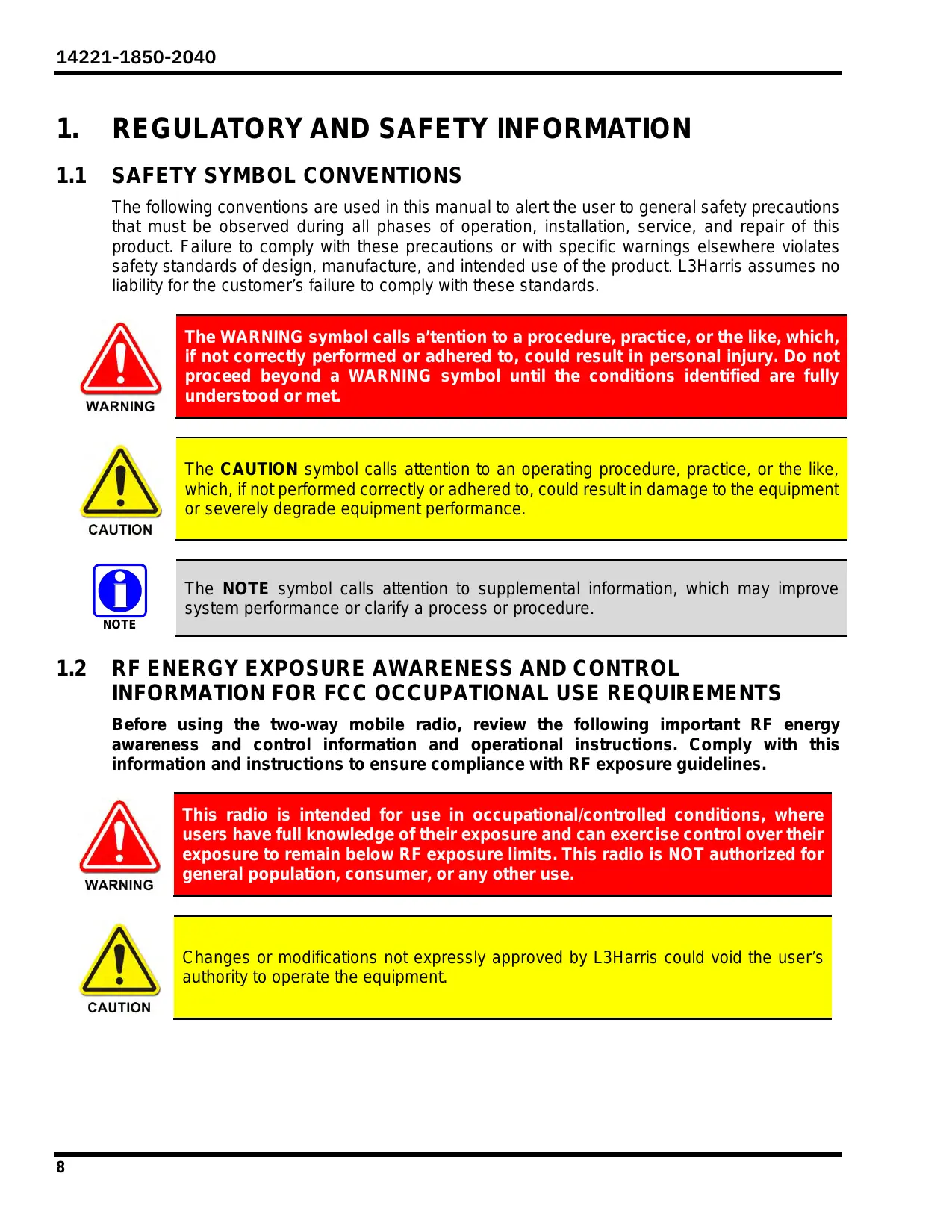
The following conventions are used in this manual to alert the user to general safety precautions that must be observed during all phases of operation, installation, service, and repair of this product. Failure to comply with these precautions or with specific warnings elsewhere violates safety standards of design, manufacture, and intended use of the product. L3Harris assumes no liability for the customer's failure to comply with these standards.

The WARNING symbol calls a 'tention to a procedure, practice, or the like, which, if not correctly performed or adhered to, could result in personal injury. Do not proceed beyond a WARNING symbol until the conditions identified are fully understood or met.

The CAUTION symbol calls attention to an operating procedure, practice, or the like, which, if not performed correctly or adhered to, could result in damage to the equipment or severely degrade equipment performance.

The NOTE symbol calls attention to supplemental information, which may improve system performance or clarify a process or procedure.
1.2 RF ENERGY EXPOSURE AWARENESS AND CONTROL INFORMATION FOR FCC OCCUPATIONAL USE REQUIREMENTS
Before using the two-way mobile radio, review the following important RF energy awareness and control information and operational instructions. Comply with this information and instructions to ensure compliance with RF exposure guidelines.

This radio is intended for use in occupational/controlled conditions, where users have full knowledge of their exposure and can exercise control over their exposure to remain below RF exposure limits. This radio is NOT authorized for general population, consumer, or any other use.

Changes or modifications not expressly approved by L3Harris could void the user's authority to operate the equipment.
This two-way radio uses electromagnetic energy in the radio frequency (RF) spectrum to provide communications between two or more users over a distance. It uses RF energy or radio waves to send and receive calls. RF energy is one form of electromagnetic energy. Other forms include, but are not limited to, electric power, sunlight, and x-rays. RF energy, however, should not be confused with these other forms of electromagnetic energy, which, when used improperly, can cause biological damage. Very high levels of x-rays, for example, can damage tissues and genetic material.
Experts in science, engineering, medicine, health, and industry work with organizations to develop standards for exposure to RF energy. These standards provide recommended levels of RF exposure for both workers and the general public. These recommended RF exposure levels include substantial margins of protection. All two-way radios marketed in North America are designed, manufactured, and tested to ensure they meet government-established RF exposure levels. In addition, manufacturers also recommend specific operating instructions to users of two-way radios. These instructions are important because they inform users about RF energy exposure and provide simple procedures on how to control it. Refer to the following websites for more information on what RF energy exposure is and how to control exposure to assure compliance with established RF exposure limits:
http://www.fcc.gov/oet/rfsafety/rf-faqs.html
http://www.osha.gov./SLTC/radiofrequencyradiation/index.html
1.3 FEDERAL COMMUNICATIONS COMMISSION REGULATIONS
Before it was marketed in the United States, the XL-85M Series mobile radio was tested to ensure compliance with FCC RF energy exposure limits for two-way mobile radios. When two-way radios are used as a consequence of employment, the FCC requires users to be fully aware of and able to control their exposure to meet occupational requirements. Exposure awareness can be facilitated using a label directing users to specific user awareness information. The radio has an RF exposure product label. Also, this manual includes information and operating instructions required to control RF exposure and to satisfy compliance requirements.
1.4 COMPLIANCE WITH RF EXPOSURE STANDARDS
The XL-85M Series mobile radio is designed and tested to comply with a number of national and international standards and guidelines regarding human exposure to RF electromagnetic energy. This radio complies with the IEEE and ICNIRP exposure limits for occupational/controlled RF exposure environment at duty-cycle times of up to 50% (50% transmit, 50% receive), and it is authorized by the FCC for occupational use. In terms of measuring RF energy for compliance with the FCC exposure guidelines, the radio's antenna radiates measurable RF energy only while it is transmitting (talking), not when it is receiving (listening), or in a standby mode.

Table 1-1 lists the recommended minimum safe lateral distances for a controlled environment and for unaware bystanders in an uncontrolled environment, from transmitting antennas (i.e., monopoles over a ground plane, or dipoles) at rated radio power for mobile radios installed in a vehicle. Transmit only when unaware bystanders are at least the uncontrolled recommended minimum safe lateral distance away from the transmitting antenna.
The XL-85M Series mobile radio complies with the following RF energy exposure standards and guidelines:
- United States Federal Communications Commission (FCC), Code of Federal Regulations; 47 CFR § 2 sub-part J.
American National Standards Institute (ANSI)/Institute of Electrical and Electronic Engineers (IEEE) C95.1-2005. - Institute of Electrical and Electronic Engineers (IEEE) C95.1-2005.
- ISED Canada Standard RSS-102, Issue 5, 2015: Spectrum Management and Telecommunications Radio Standards Specification. Radio Frequency (RF) Exposure Compliance of Radiocommunication Apparatus (All Frequency Bands).
Based on the highest radiated RF power and the highest antenna gain in antennas to be used with the XL-85M Series mobile radio, the distances listed are considered as safe distances for controlled and uncontrolled environments with the XL-85M Series mobile radio transmitting at a maximum 50% duty cycle.
1.4.1 Mobile Antennas
The antenna(s) for the radio must be installed in accordance with the antenna installation procedures presented in the radio's Installation Manual. Installation guidelines presented in the Installation Manual are limited to metal-body motor vehicles or vehicles with appropriate ground planes.
Use only approved/supplied antenna(s) or an approved replacement antenna. Unauthorized antennas, modifications, or attachments can cause the FCC RF exposure limits to be exceeded. Refer to Section 3.5 for the list of approved antennas.
Distances shown in the table below are for the highest gain antennas that L3Harris offers with this product (the part numbers shown are the highest gain antennas). See Table 3-1 for antenna part numbers.
Table 1-1: Calculated Minimum Safe Distance from LMR Antenna
| ANTENNA | GAIN (DBI) | PART # | BAND (MHZ) | UNCONTROLLED EXPOSURE | CONTROLLED EXPOSURE | ||
| UNITED STATES (CM) | CANADA (CM) | UNITED STATES (CM) | CANADA (CM) | ||||
| Antenna, Element, 700/800 MHz, 3 dB | 5.15 | AN-225001-001 | 700 | 88 | 128 | 40 | 47 |
| Antenna, Element, 800/900, 5 dB | 7.15 | 14050-6611-01 | 800 | 116 | 170 | 52 | 63 |
| Antenna, Yagi, 700 MHz 10 dB | 12.15 | AN-025137-007 | 700 | 196 | 286 | 89 | 105 |
| Antenna, Yagi, 800 MHz 10 dB | 12.15 | AN-025137-008 | 800 | 206 | 302 | 92 | 113 |
1.4.2 Approved Accessories
The radio has been tested and meets FCC RF guidelines when used with accessories supplied or designated for use with it. Use of other accessories may not ensure compliance with the FCC's RF exposure guidelines and may violate FCC regulations. For a list of approved accessories, refer to the radio's Installation Manual and/or the Products and Services Catalog.
1.4.3 Contact Information
For additional information on RF exposure and other information, contact L3Harris using one of the contact links listed in Section 10.
1.5 REGULATORY APPROVALS
1.5.1 Applicable Type Acceptance/Certification Numbers
FCC Type Acceptance:
XL-85M:
OWDTR-0170-E
Applicable FCC Rules:
Part 2, Part 15, and Part 90
XL-CH2
OWDTR-0171-E
Applicable FCC Rules:
Part 15
ISED Canada Certification:
XL-85M:
3636B-0170
Applicable ISED Canada Rules:
RSS-247, RSS-119, ICES-003 Issue 6
XL-CH2
3636B-0171
Applicable ISED Canada Rules:
RSS-247, RSS-119, ICES-003 Issue 6
1.5.2 FCC Part 15
This device complies with Part 15 of the FCC Rules. Operation is subject to the following two conditions:
- This device may not cause harmful interference, and
- This device must accept any interference received, including interference that may cause undesired operation.
NOTE: This equipment has been tested and found to comply with the limits for a Class A digital device, pursuant to part 15 of the FCC Rules. These limits are designed to provide reasonable protection against harmful interference when the equipment is operated in a commercial environment. This equipment generates, uses, and can radiate radio frequency energy and, if not installed and used in accordance with the instruction manual, may cause harmful interference to radio communications. Operation of this equipment in a residential area is likely to cause harmful interference in which case the user will be required to correct the interference at his own expense.
1.5.3 ISED Canada
This device contains licence-exempt transmitters(s)/receiver(s) that comply with Innovation, Science and Economic Development Canada's licence-exempt RSS(s). Operation is subject to the following two conditions:
(1) This device may not cause interference.
(2) This device must accept any interference, including interference that may cause undesired operation of the device.
1.6 OCCUPATIONAL SAFETY GUIDELINES AND SAFETY TRAINING INFORMATION
To ensure bodily exposure to RF electromagnetic energy is within the FCC allowable limits for occupational use. Always adhere to the following basic guidelines:
- The push-to-talk button should only be depressed when intending to send a voice message.
- The radio should only be used for necessary work-related communications.
- The radio should only be used by authorized and trained personnel. It should never be operated by children.
- Do not attempt any unauthorized modification to the radio. Changes or modifications to the radio may cause harmful interference and/or cause it to exceed FCC RF exposure limits. Only qualified personnel should service the radio.
- Always use only authorized accessories (antennas, control heads, speakers/mics, etc.). Use of unauthorized accessories can cause the FCC RF exposure compliance requirements to be exceeded.
The information listed above provides the user with information needed to make him or her aware of a RF exposure, and what to do to assure that this radio operates within the FCC exposure limits of this radio.
1.7 COMMON HAZARDS

The operator of any mobile radio should be aware of certain hazards common to the operation of vehicular radio transmissions. Possible hazards include but are not limited to the following:
- Explosive Atmospheres – Just as it is dangerous to fuel a vehicle while its engine is running, be sure to turn the radio OFF while fueling the vehicle. If the radio is mounted in the trunk of the vehicle, DO NOT carry containers of fuel in the trunk.
Areas with potentially explosive atmosphere are often, but not always, clearly marked. Turn the radio OFF when in any area with a potentially explosive atmosphere. It is rare, but not impossible that the radio or its accessories could generate sparks. - Interference To Vehicular Electronic Systems - Electronic fuel injection systems, electronic anti-skid braking systems, electronic cruise control systems, etc., are typical of the types of electronic devices that can malfunction due to the lack of protection from radio frequency (RF) energy present when transmitting. If the vehicle contains such equipment, consult the dealer for the make of vehicle and enlist his aid in determining if such electronic circuits perform normally when the radio is transmitting.
- Electric Blasting Caps – To prevent accidental detonation of electric blasting caps, DO NOT use two-way radios within 1000 feet (305 meters) of blasting operations. Always obey the "Turn Off Two-Way Radios" (or equivalent) signs posted where electric blasting caps are being used. (OSHA Standard: 1926.900).
- Radio Frequency Energy - To prevent burns or related physical injury from radio frequency energy, do not operate the transmitter when anyone outside of the vehicle is within the
minimum safe distance from the antenna as specified in Table 1-1. Refer to Section 1.2 for additional information.
- Vehicles Powered by Liquefied Petroleum (LP) Gas - Radio installation in vehicles powered by liquefied petroleum gas, where the LP gas container is in the trunk or other sealed-off space within the interior of the vehicle, must conform to the National Fire Protection Association standard NFPA 58. This requires:
The space containing the radio equipment must be isolated by a seal from the space containing the LP gas container and its fittings.
Outside filling connections must be used for the LP gas container.
The LP gas container space shall be vented to the outside of the vehicle.
- Vehicles Equipped with Airbags – For driver and passenger safety, avoid mounting the radio's control head (or any other component) above or near airbag deployment areas. In addition to driver-side and passenger-side front-impact airbags, some vehicles may also be equipped with side-impact airbags. For occupant safety, verify the location of all airbags within the vehicle before installing the radio equipment.

CAUTION
The Vehicle Communications Hub (VCH) runs at elevated temperatures that can be up to 45^ above ambient.
1.8 SAFE DRIVING RECOMMENDATIONS
The American Automobile Association (AAA) advocates the following key safe driving recommendations:
- Read the literature on the safe operation of the radio.
- Keep both hands on the steering wheel and the microphone in its hanger whenever the vehicle is in motion.
- Place calls only when the vehicle is stopped.
- When talking from a moving vehicle is unavoidable, drive in the slower lane. Keep conversations brief.
- If a conversation requires taking notes or complex thought, stop the vehicle in a safe place and continue the call.
- Whenever using a mobile radio, exercise caution.
1.9 OPERATING RULES AND REGULATIONS
Two-way radio systems must be operated in accordance with the rules and regulations of the local, regional, or national government.
In the United States, the XL-85M Mobile radio must be operated in accordance with the rules and regulations of the Federal Communications Commission (FCC). Operators of two-way radio equipment must be thoroughly familiar with the rules that apply to the radio operation. Following these rules helps eliminate confusion, assures the most efficient use of the existing radio channels, and results in a smoothly functioning radio network.
When using a two-way radio, remember these rules:
- It is a violation of FCC rules to interrupt any distress or emergency message. The radio operates in much the same way as a telephone "party line." Therefore, always listen to make sure the channel is clear before transmitting. Emergency calls have priority over all other messages. If someone is sending an emergency message – such as reporting a fire or asking for help in an accident, do not transmit unless assistance can be offered.
- The use of profane or obscene language is prohibited by Federal law.
- It is against the law to send false call letters or false distress or emergency messages. The FCC requires keeping conversations brief and confined to business. Use coded messages whenever possible to save time.
- Using the radio to send personal messages (except in an emergency) is a violation of FCC rules. Send only essential messages.
- It is against Federal law to repeat or otherwise make known anything overheard on the radio. Conversations between others sharing the channel must be regarded as confidential.
- The FCC requires self-identification at certain specific times by means of call letters. Refer to the rules that apply to the operation for the proper procedure.
- No changes or adjustments shall be made to the equipment except by an authorized or certified electronics technician.

Under U.S. law, operation of an unlicensed radio transmitter within the jurisdiction of the United States may be punishable by a fine of up to (10,000, imprisonment for up to two (2) years, or both.
1.10 OPERATING TIPS
The following conditions tend to reduce the effective range of two-way radios and should be avoided whenever possible:
- Operating the radio in areas of low terrain, or while under power lines or bridges.
- Obstructions such as mountains and buildings.

In areas where transmission or reception is poor, communication improvement may sometimes be obtained by moving a few yards in another direction or moving to a higher elevation.
1.11 CITIZENS BAND OPERATION IN AUSTRALIA/NEW ZEALAND
- Use of the citizen band radio service is licensed in Australia by ACMA Radiocommunications (Citizens Band Radio Stations) Class License and in New Zealand by the Ministry of Economic Development (MED) General User Radio License (GURL) for Citizens Band Radio, and operation is subject to conditions contained in those licenses.
- In Australia, except in an emergency, a CB transmitter shall not be operated on UHF emergency channels 5 and 35 and no voice transmissions are permitted on data (telemetry/telecommand) channels 22 and 23. In the event that additional
telemetry/telecommand channels are approved by the ACMA, these channels shall be added to those currently listed where voice transmission is inhibited.
- Always listen in on a channel (or observe a channel-busy indicator) to ensure it is not already being used before transmitting.
- UHF CB repeater operation must avoid operation on locally used repeater input channels (which will be in the range of channels 31 to 38, and channels 71 to 78 when they are authorized) or locally used repeater receiving channels (which will be in the range channels 1 to 8, and channels 41 to 48 when they are authorized), unless long-distance communication via the repeater facility is specifically required. NOTE: In Australia, channel 11 is the customary calling channel for establishing communication and channel 40 is the customary road vehicle channel.
- Possible operational issues during the changeover from 25kHz to 12.5kHz channel spacing that may cause system performance degradation is if a WB channel gets placed 12.5kHz away from a NB or WB channel. In this case, adjacent channel interference would increase and performance would degrade. There would also be some level of performance degradation if a NB transmission is received on a WB channel and vice-versa. L3Harris equipment meets the emission mask which minimizes any impact.
2. RENSEIGNEMENTS SUR LA RÉGLEMENTATION ET SÉCURITÉ
2.1 CONVENTIONS SUR LES SYMBOLES DE SECURITE
2.3 CONFORMITE AUX NORMES D'EXPOSITION AUX RF
- Federal Communications Commission (FCC) américa, le Code of Federal Regulations ; 47 CFR § 2 sous-partie J.
American National Standards Institute (ANSI)/Institute of Electrical and Electronic Engineers (IEEE) C95.1-2005. - Institute of Electrical and Electronic Engineers (IEEE) C95.1-2005.
- ISED Standard RSS-102, número 5, 2015: Spectrum Management and Telecommunications Radio Standards Specification. Radiofrequency Exposure Compliance of Radiocommunication Apparatus (All Frequency Bands).
The XL-85M Mobile Radio provides the advanced connectivity that users require while addressing evolving voice and data communications. It meets MIL-STD-810H for durability. XL-85M Mobile Radios support P25 Trunking, P25 Conventional, EDACS®, analog conventional, and BeOn® operation over a Wi-Fi network. The standard XL-85M installation is a front-mount configuration. However, an optional remount-mount conversion kit is available that supports conversion to a remote-mount configuration.
For options and accessories, refer to Section 3.5. Additional accessories may have been added since publication of this manual; refer to the Products and Services Catalog or contact L3Harris for more information.
3.2 XL-CH2 CONTROL HEAD
The XL-CH2 Control Head is a networked device that uses a wired Ethernet connection to provide remote control of the radio. It includes a color LCD graphical user interface and physical knobs and buttons to allow a user to control the radio or view its status. The control head also provides multiple audio interfaces to capture and play real-time audio.
The XL-CH2 Control Head's design provides a tactile interface optimized so that users can keep their eyes on the road and still operate the radio. Controls and display are laid out to give instant access to primary use cases.
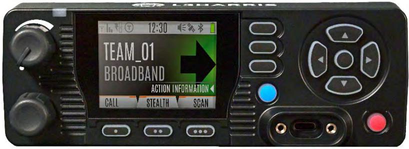
Figure 3-1: XL-CH2 Control Head
Standard Control Head Features include:
Wi-Fi (802.11B, G, N)
- Bluetooth 4.2
Hi-visibility Color Display
USB-C Microphone Connector
3.3 KEYPAD MOBILE MICROPHONE (KMM)
The XL-85M Mobile Radio supports the Keypad Mobile Microphone (KMM).
The KMM features include:
- PTT and Microphone (with Dual-Mic Noise Cancellation Capability)
Four-way Navigation Pad (Up, Down, Left, Right) with Center-Select - One-dot, two-dot, three-dot programmable buttons, and Menu button that function the same as the XL Mobile Control Head buttons
12-button Alpha-numeric Keypad for alpha-character entry - Mil-Std 810G Ruggedness
IP-65 Immersion Rating
USB Microphone Connector

Figure 3-2: Keypad Mobile Microphone
3.4 CLEANING
Keep the exterior of the radio equipment clean. This includes the radio, control head, microphone, and speaker. Periodically clean them using either the Light-duty cleaning procedure or in extreme cases the Heavy-duty cleaning procedure as described in the maintenance manual.
3.5 OPTIONS AND ACCESSORIES
Only use L3Harris approved accessories. Refer to L3Harris' Products and Services Catalog for the complete list of options and accessories available.
Table 3-1: Options and Accessories
| DESCRIPTION | PART # | OPTION # |
| ANTENNAS | ||
| Antenna, Flex, Heavy-Duty, 136-870 MHz | 12099-0300-01 | |
| Antenna, Element, Multiband, 136-870 MHz, 0 dB | 12099-0310-01 | |
| Antenna, Yagi, 700 MHz, 10 dB Gain | AN-025137-007 | |
| Antenna, Yagi, 800 MHz, 10 dB Gain | AN-025137-008 | |
| Antenna, 700/800 MHz Yagi, 6.5 dB Gain | AN-025137-010 | |
| Antenna, Element, 800/900 MHz, 3 dB | 14050-6610-01 | |
| Antenna, Element, 800/900 MHz, 5 dB | 14050-6611-01 | |
| Antenna, Base, Standard Roof Mount Low Loss | AN-125001-002 | |
| Antenna, Base, Thick Roof Mount Low Loss | AN-125001-004 | |
| Antenna, Base, Magnetic Mount Low Loss | AN-125001-008 | |
| Mount, NMO Antenna, Magnetic, Heavy-Duty | 12099-0370-01 | |
| Antenna, Element, 700/800 MHz 3 dB | AN-225001-001 | |
| Antenna, GPS, Roof Mount | AN-025187-001 | |
| Antenna, GPS, Magnet Mount | AN-025187-003 | |
| Antenna, Base, Standard Roof Mount Low Loss GPS | AN-125001-006 | |
| Antenna, Broadband Mobile, 698-2700 MHz | 12099-0380-01 | |
| Antenna, Element, Flexible, VHF/UHF/700/800 MHz | 14050-6600-01 | |
| MISCELLANEOUS | ||
| XL Mobile Accessory Cable | 14002-0174-50 | |
| XL Mobile Ethernet Cable, Overmold, 45 cm | 14050-6300-01 | |
| XL Mobile Ethernet Cable, Overmold, 9 m | 14050-6300-02 | |
| XL Control Head DC Power Cables | CA-012616-001 | |
| DC Power Cables | CA-012365-001 | |
| XL Standard Mobile Microphone | 14050-6010-01 | |
| External Mobile Speaker | 14050-6100-01 | |
| Radio Mounting Bracket | 14050-6200-01 | |
| XL Control Head Mounting Bracket | 14050-6210-01 | |
| XL Mobile Desktop Microphone, DB9 | MC-014121-003 | |
| XL Mobile USB and Speaker Cable | 14002-0174-51 | |
| XL Mobile Speaker Accessory Cable, 5.5 Feet | 14002-0174-52 | |
| XL Mobile USB Data Cable | 14002-0174-55 | |
| XL Speaker Cable, 20 Feet | 14002-0174-59 | |
| XL Desktop Accessory Cable | 14002-0174-61 | |
| XL Radio Waterproof Accessory Port Cover | 14002-0174-56 | |
| XL Control Head Waterproof Accessory Port Cover | 14002-0174-57 | |
| Control Head Waterproof RJ45 Port Cover | 14002-0174-58 | |
| Waterproof Control Head Mic Port Cover | 14002-0174-60 | |
| VCH CCM USB Port Waterproof Cover | 14002-0174-66 | |
| XL Mobile Keypad Microphone | 14050-6020-01 | |
3.6 RELATED PUBLICATIONS
The following publications contain additional information about the radio and related products:
| MANUAL NUMBER | DESCRIPTION |
| 14221-1850-2050 | XL-85M Mobile Product Safety Manual |
| 14221-1850-1020 | XL-85M Mobile Quick Guide |
| 14221-1850-4060 | XL-85M Mobile Installation Manual |
| 14221-1850-5020 | XL-85M Mobile Maintenance Manual |
| 14221-1850-4070 | XL-85M Mobile Radio Front to Remote-Mount Conversion Kit Installation Manual |
| 14221-1800-8010 | XLP Software Release Notes |
| 14221-1850-1010 | Keypad Mobile Microphone (KMM) Quick Guide |
| 14221-1850-2020 | XL Rugged Hand-Held Controller (RHHC) Operator's Manual |
| MM1000019423 | Key Manager and Key Admin Overview and Operation Manual |
| MM1000019424 | Key Manager and Key Loader Overview and Operation Manual |
| 14221-2100-3000 | Advanced Access Control/Radio Personality Manager Overview Manual |
| 14221-1100-8170 | Radio Personality Manager 2 (RPM2) Software Release Notes |
| 14221-1100-2060 | RPM2 User's Manual |
| 14221-7200-6140 | Noise Cancellation Feature Manual |
The product safety manual and the quick guide are included with the radio equipment package when the radio ships from the factory. All publications listed above are available at https://premier.pspc.harris.com via an Information Center login and Tech-Link.
4. BASIC OPERATION
4.1 RADIO CONTROLS

Figure 4-1: Control Head Controls
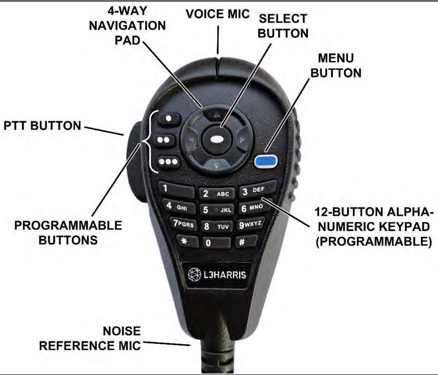
Figure 4-2: Keypad Mobile Microphone (KMM) Controls
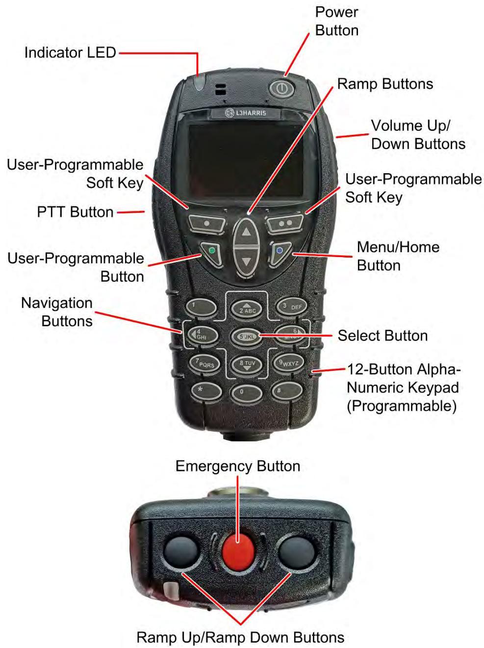
Figure 4-3: XL Rugged Hand-Held Controller (RHHC)

NOTE
Table 4-1 describes the default functions of buttons, knobs, and controls. Some can be programmed for different functions; see Section 6.6 for more information.

NOTE
For full descriptions of the XL RHHC controls, indicators, and connectors, refer to the XL RHHC Operator's Manual, 14221-1850-2020.
Table 4-1: Radio Controls, Indicators, and Connectors
| CONTROL/INDICATOR | FUNCTION |
| Power On/Off Volume Control | Turn knob clockwise to power on the radio and increase volume. Turn counter-clockwise to decrease volume and put the radio into standby. Minimum volume levels can be programmed into the radio to prevent missed calls due to a low volume setting. |
| Group/Channel Selection | • Rotate to select the available groups or channels. • While on the main display, press this knob to show the programmable button function labels. Press again to hide labels. |
| Microphone Connector | Connection for hand-held microphones and for programming cable. |
| Emergency Button | Press to declare an emergency. An Emergency Key Delay can be programmed in the radio. This delay defines the length of time the emergency button must be held before an emergency transmission is sent. |
| Navigation Pad [Left, Right, Up, Down, and Select] | Navigates menu items. In addition: • Press the left navigation button while on the main display to access Channel Information. • Press the down navigation button while on the main display to display the functions assigned to programmable buttons and to Ext I/O In. • Press the up navigation button to display Missed Call info. • Press the right navigation button to end or reject an I-Call. • The Select button selects the currently highlighted menu item, similar to an Enter button. |
| 12-Button Alpha-Numeric Keypad (KMM) | By default, used to enter text or numbers. Can be programmed for various functions (see Section 6.6). |
| Menu Button | From the Main Display, press this button to access the menu. Depending on radio programming, pressing this button accesses the top-level list of menus or accesses the Call Menu directly. While in a menu, press this button to return to the main display. |
| User-Programmable Soft Keys and Programmable Buttons | Programmable, dynamic keys. See Section 6.6 for the functions that can be programmed. Press the Group/Channel Selection Knob to display the function labels for each button. |
| Indicator LED | Indicates radio status: • Red = actively transmitting. • Green = actively receiving. • Orange = actively transmitting encrypted. |
4.2 BEFORE FIRST USE
Make sure the XL-85M Mobile has:
- Personality and radio programmed using RPM2
- Encryption keys loaded if using encrypted channels
- Personality activated
4.3 POWER ON AND SET VOLUME
The power switch and volume control are the same knob on the radio (see Figure 4-1). Turn the Power/Volume Knob clockwise to power on radio and increase the volume. The radio can be programmed to play an audible tone when changing the volume.

NOTE
A minimum volume level can be programmed into the radio to prevent missed calls due to a low volume setting.
4.4 VIDA® ID
VIDA ID provides the capability to provision the VIDA User Personality configured in the UAS to radios operating on P25 networks via a User Login. Each personality can contain up to 16 profiles and each profile can contain up to 16 Talk Groups. Refer to Section 9.1 for a list of potential login and provisioning error messages and what to do if they occur.
4.4.1 User Login
User Login enables multiple radio users to pick a radio from a fleet pool and enter unique credentials to log into the P25 system. Upon successful login, the Alias associated with the radio user is displayed at various end points in the P25 system.
A user can login on up to three (3) devices simultaneously. For example, if the "same user" is logged into a portable radio and mobile radio, the P25 system can differentiate the subscribers while transparently displaying the alias to other users.
Login can be initiated by a menu option, a button programmed for user login, or by selecting a P25 system that requires login. To login manually:
- From the UTILITY radio menu, select USER LOGIN, or press the button programmed for User Login.
- Enter the System ID, User ID, and Password, as required.
- Select Login.
4.4.2 Provisioning
If provisioning is enabled via radio programming and the user has successfully logged in, the VIDA User Personality configured in the UAS is provisioned to the radio. When no VIDA Provisioned database is available, the radio operates using the RPM2-programmed personality.
4.5 RADIO DISPLAYS
Figure 4-4 shows a sample front display while on the main screen. The main screen appears after power up or after exiting the menus.
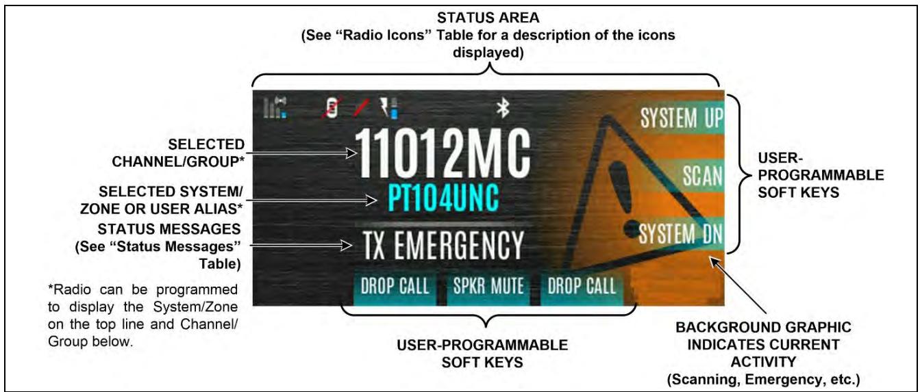
Figure 4-4: Sample Main Front Display

NOTE
The radio can be programmed to display the User ID on the System line of the display.
Table 4-2 describes some of the icons that may be displayed by the radio. The radio menu also contains an icon glossary in the Utility Menu (see Section 4.7). Icons and their location can be customized using RPM2.
Table 4-2: Radio Icons
| ICON | DESCRIPTION | ICON | DESCRIPTION | ICON | DESCRIPTION |
| (<=) | (Blue) Trunked Signal Strength | * | Bluetooth Enabled | Monitor On | |
| (<=) | (Red) TX Power | * | Bluetooth Connected | VDOC | |
| (<=) | (Green) Receive Signal Strength | Encryption Enabled | Receiving Data | ||
| (<=) | (No Color) Channel Idle | Global Encryption | Transmitting Data | ||
| (<=) | (Orange) Transmitting Encrypted | OTAR Disabled | Alert(s) Present | ||
| T | Talkaround Enabled | OTAR Registered | Vote Scanning | ||
| A! | Failsoft | OTAR Registering | Scanning Enabled | ||
| Vehicular Repeater | OTAR Rekeying | Emergency | |||
| Vehicular Repeater Enabled | Transmit Power Level High | RX Mail | |||
| Wi-Fi Signal Strength Indicator | Transmit Power Level Low | Noise Cancellation Enabled | |||
| Wi-Fi Network Currently Connected | RX Only | Fire Speaker Mic Attached | |||
| Wi-Fi Network in Process of Connecting | Add New Wi-Fi Client | Nuisance Channel | |||
| Wi-Fi Clients Connected | Speaker Muted | TX Disabled | |||
| GPS Tracking | Tones Disabled | Conventional Site Unregistered | |||
| IP Address Unassigned | PTT Disabled | Conventional Site Registered | |||
| Ethernet Link Down | A wearable Bluetooth device is attached (e.g., Bluetooth Microphone) | Type 99 Enabled | |||
| GPS Antenna Detached | Remote Application Active |
4.6 STATUS MESSAGES
The radio may display various radio Status Messages during operation. These messages are described in Table 4-3.
Table 4-3: Status Messages
| MESSAGE | DESCRIPTION |
| PTT DENIED | P25 Trunked and EDACS® - The radio or talkgroup is not authorized to operate on the selected system and/or talkgroup. |
| CALL QUEUED | P25 Trunked and EDACS - The system has placed the call in a request queue. |
| SYSTEM BUSY | P25 Trunked and EDACS - The system is busy, no channels are currently available, the queue is full, or an individual call is being attempted to a radio that is currently transmitting. |
| SCANNING | The radio is scanning. |
| TX EMERGENCY | An emergency call is being transmitted. |
| RX EMERGENCY | An emergency call is being received. The radio displays the unit name or unit ID. |
| WIDE AREA SCAN | P25 Trunked and EDACS - The radio has entered the Wide Area Scan mode to search for a new system. |
| INVALID TALKGROUP | P25 Trunked and EDACS - The current talkgroup is not valid for the current system. This could happen if the site denies registration due to an unrecognized talkgroup ID. |
| INVALID UNIT | P25 Trunked and EDACS - The current unit is not valid for the current system. |
| REGISTERING | P25 Trunked only - Displayed when the radio is performing a registration/affiliation on a P25 trunking site. |
| CTRL CHANNEL SCAN | P25 Trunked and EDACS - The control channel is lost and the radio has entered the Control Channel Scan mode to search for the control channel (usually out of range indication). |
| BAND SCANNING | P25 Trunked – Only displayed if the system is configured for “EnhancedCC” mode of operation. When the radio cannot find a Control Channel in either the trunked frequency set or the list of discovered adjacencies, the radio can perform a full spectrum frequency scan to find a new Control Channel. |
| MISSED CALL | P25 Modes and EDACS – Another user has tried to call or page this radio. The user can view who the caller was by pressing the up navigation button. |
| OTAR REKEY COMPLETE | OTAR Rekey operation completed successfully. |
| IGNITION OFF | The radio has detected the ignition switch/ key is off and the Ignition Shut-Off Timer is active. When the Ignition Shut-Off Timer expires, the radio will power off. See Section 4.33 for more information. |
4.7 PREDEFINED MENU LAYOUTS
Depending on radio programming, some menu options described in this manual may not be available. The radio supports three predefined menu layouts: Full, Custom, and Restricted. Table 4-4 details what is available in each layout:

NOTE
The Custom predefined menu layout allows the administrator to customize the list of menu items that are available to the radio user. Table 4-4 lists the default settings. See Section 4.8 for a description of menus.
Table 4-4: Predefined Menu Layouts
| MENU | FULL | CUSTOM (Default SETTINGS) | RESTRICTED |
| CALL: | YES | YES | YES |
| EXIT EMERGENCY | YES | YES | YES |
| TALKAROUND | YES | YES | YES |
| INDIVIDUAL CALL | YES | YES | YES |
| CHANGE TALKGROUP | YES | YES | YES |
| PHONE CALL | YES | YES | YES |
| DIRECT DIAL | YES | YES | YES |
| CALL ALERT/PAGE | YES | YES | YES |
| CHANNEL GUARD | YES | YES | YES |
| RECEIVE CG | YES | YES | YES |
| TRANSMIT CG | YES | YES | YES |
| AUDIO PLAYBACK | YES | YES | YES |
| TONE ENCODE | YES | YES | YES |
| T99 | YES | YES | YES |
| EMERGENCY TIMER | YES | YES | NO |
| SCAN: | YES | YES | YES |
| ENABLE/DISABLE SCAN | YES | YES | YES |
| VIEW SCAN LIST | YES | YES | NO |
| EDIT ZONE SCAN LIST | YES | NO | NO |
| VIEW CUSTOM CHANNELS | YES | YES | NO |
| EDIT CUSTOM SCAN LIST | YES | NO | NO |
| CUSTOM SCAN | YES | YES | NO |
| SITE ROAM | YES | YES | NO |
| SITE ALIAS | YES | YES | NO |
| SECURITY: | YES | YES | YES |
| ENCRYPTION ENABLE | YES | YES | YES |
| ZEROIZE | YES | NO | NO |
| GLOBAL CKR ENABLE | YES | NO | NO |
| GCKR KEY SELECT | YES | NO | NO |
| ACTIVE KEY SET | YES | YES | YES |
| KEY LIST | YES | YES | NO |
| OTAR ENABLE | YES | YES | NO |
| OTAR REKEY | YES | YES | YES |
| KVL Mode | YES | YES | YES |
| KVL Mode LLA | YES | YES | YES |
| MESSAGE: | YES | YES | YES |
| RADIO STATUS | YES | YES | NO |
| RADIOMESSAGE | YES | YES | NO |
| TEXTLINK MESSAGES | YES | YES | NO |
| TEXTLINK FORMS | YES | YES | NO |
| TEXTLINK MAILBOX | YES | YES | NO |
| FAULTS | YES | YES | YES |
| AUDIO: | YES | NO | NO |
| MASTER | YES | YES | NO |
| SPEAKER | YES | NO | NO |
| NOISE CANCELLATION | YES | NO | NO |
| TONES ENABLE | YES | NO | NO |
| KEYPAD TONES | YES | NO | NO |
| VOICE ANNUNCIATION | YES | NO | NO |
| DISPLAY SETTINGS: | YES | YES | YES |
| FRONT BACKLIGHT | YES | YES | YES |
| FRONT BRIGHTNESS | YES | YES | YES |
| FRONT TIMEOUT | YES | YES | YES |
| FRONT DISPLAY OFF | YES | YES | YES |
| DAY/NIGHT TOGGLE | YES | YES | YES |
| ACCENT BACKLIGHT | YES | YES | YES |
| ACCENT BRIGHTNESS | YES | YES | YES |
| ACCENT TIMEOUT | YES | YES | YES |
| LEDS | YES | YES | YES |
| BLUETOOTH SETTINGS: | YES | YES | NO |
| BLUETOOTH ENABLE | YES | YES | NO |
| BLUETOOTH DISCOVERABLE | YES | YES | NO |
| VOLUME CONTROL | YES | YES | NO |
| BLUETOOTH SPEAKER | YES | YES | NO |
| EXTERNAL SPEAKER | YES | YES | NO |
| BLUETOOTH PAIRING | YES | YES | NO |
| BLUETOOTH PAIRING ADD | YES | YES | NO |
| BLUETOOTH PAIRING DELETE | YES | YES | NO |
| CLOCK SETTINGS: | YES | YES | NO |
| DISPLAY FORMAT | YES | YES | NO |
| TIME ZONE | YES | YES | NO |
| PROGRAM: | YES | YES | NO |
| ACTIVATE PLAN | YES | YES | NO |
| ACTIVATE PROFILE | YES | YES | NO |
| GPS SETTINGS: | YES | YES | NO |
| GPS ENABLE | YES | NO | NO |
| POSITION INFO | YES | NO | NO |
| ANGULAR UNITS | YES | NO | NO |
| LINEAR UNITS | YES | NO | NO |
| POSITION FORMAT | YES | NO | NO |
| SA OVER NETWORK | YES | NO | NO |
| MAINTENANCE: | YES | YES | YES |
| RADIO INFO | YES | YES | NO |
| TCXO TUNING | YES | NO | NO |
| TESTS | YES | YES | NO |
| PATTERN TEST | YES | YES | NO |
| IBER TEST | YES | YES | NO |
| PHASE II IBER | YES | YES | NO |
| RSSI DISPLAY | YES | YES | YES |
| PHASE II DISPLAY | YES | YES | NO |
| FEATURE INFO | YES | YES | NO |
| CHANGE LANGUAGE | YES | YES | NO |
| CHANGE PIN | YES | YES | YES |
| WIFI ACCESS POINT: | YES | YES | YES |
| WIFI AP STATE | YES | YES | NO |
| WIFI AP CLIENTS | YES | YES | NO |
| WIFI: | YES | YES | NO |
| WIFI STATE | YES | YES | NO |
| WIFI NETWORKS | YES | YES | NO |
| ADD NETWORK | YES | YES | NO |
| REMOVE NETWORK | YES | YES | NO |
| VIEW/EDIT NETWORK | YES | YES | NO |
| ICON GLOSSARY | YES | YES | YES |
| USER-login: | YES | YES | YES |
| SYSTEM ID | YES | YES | YES |
| UNIT ID | YES | YES | YES |
| MEMORY | YES | YES | YES |
| DEVICE MANAGEMENT | YES | YES | YES |
| STEALTH MODE SETTINGS | YES | NO | NO |
| LCD ENABLED | YES | NO | NO |
| LED ENABLED | YES | NO | NO |
| BACKLIGHT ENABLED | YES | NO | NO |
| SIDE/ALERT TONES ENABLED | YES | NO | NO |
| MOBILE MAIN AUDIO PATH ENABLED | YES | NO | NO |
| VOICE ANNUNCIATION ENABLED | YES | NO | NO |
| CHANNEL/GROUP KNOB ENABLED | YES | NO | NO |
| ZONE | YES | YES | NO |
| CTZ EDIT | YES | YES | NO |
4.8 MENU
Press the Menu button while on the main display to access the menu. Depending on radio programming, this button accesses the top-level list of menus (Figure 4-5) or it accesses the Call Menu directly (Figure 4-6). When in a menu, press the Menu button to return to the main display.
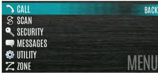
Figure 4-5: Top-Level Menu Listing
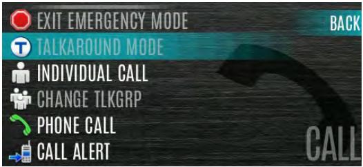
Figure 4-6: Call Menu
From a sub-menu (e.g., Call Menu), press the left or right navigation buttons to scroll through other menus (e.g., Scan, Security, etc.). Press the up or down navigation buttons or rotate the Group/Channel Select knob to scroll through available options in a sub-menu. Refer to Figure 4-1 for button location. Press the Select Button to choose, activate, or toggle the selected item; similar to an enter key.
Table 4-5 provides a high-level overview of the menu layout. Depending on radio programming, some menu options may not be available. Three predefined menu options are available: Full, Custom, and Restricted. Refer to Table 4-4 for which menu items are visible for each.
Table 4-5: Menu Navigation
| MENUS | DESCRIPTION |
| CALL MENU: | |
| EXIT EMERGENCY MODE | Exits emergency. See Section 4.29 for more information. |
| TALKAROUND MODE | Enable/disable talkaround. See Section 4.19 for more information. |
| TONE ENCODE | Analog conventional only – Transmits a programmed tone sequence on the current radio system and channel. See Section 5.18 for more information. |
| INDIVIDUAL CALL | Allows you to select an individual for an individual call. See Section 4.14 for more information. |
| PHONE CALL | Allows the user to initiate a telephone interconnect call. See Section 4.22 for more information. |
| CHANGE TLKGRP | Change the selected talkgroup. See Section 4.12. |
| CALL ALERT | Select a group for Call Alert transmission. See Section 4.20. |
| CHANNEL GUARD | Select the Transmit and/or Receive Channel Guard tone. See Section 4.18. |
| T99 TOGGLE | Enable/disable T99. See Section 4.20 for more information. |
| EMERGENCY TIMER | Enable/disable the Emergency Check In Timer. See Section for more information. |
| SCAN MENU: | |
| START SCAN/STOP SCAN | Start or stop scan operation. See Sections 4.24 and 4.25. |
| SCAN Lists | View/Edit available scan lists. See Section 5.13. |
| ASSIGNED CUSTOM LIST | Create, View, and Edit Custom Scan Lists. See Section 5.13.6. |
| SITE ROAMING | Enable/Disable Wide Area System Scan. See Section 5.13.7. |
| SITE ALIAS | Select an available site from this list to lock the radio to; i.e., prevent the radio from roaming. This is also known as Site Lock. See Section 5.13.8 for more information. |
| SECURITY MENU: | |
| ZEROIZE KEYS | Removes all encryption keys from the radio. See Section 5.19.1. |
| ENCRYPTION | Enable/Disable encryption. See Section 4.17. |
| GLOBAL ENCRYPTION | Enable/Disable Global Encryption. See Section 5.19.3. |
| GLOBAL KEY | Select the Global Key. Only available if Global Encryption is Enabled. See Section 5.19.3. |
| ACTIVE KEYSET | Select the Active Keyset. See Section 5.19.4. |
| KEY LIST | View available key lists. See Section 5.19.5. |
| OTAR | Enable/disable Over-the-Air Rekeying (OTAR). See Section 5.19.7. |
| OTAR REKEY | Request that the KMF updates the keys in the radio. See Section 5.19.7. |
| KVL MODE | Enables the radio to have keys loaded using the Motorola KVL. See Appendix B.2.3. |
| KVL MODE LLA | Puts the radio into KVL LLA Mode, allowing the user to load Link-Layer Authentication (LLA) Keys via a KVL-5000. |
| MESSAGE MENU: | |
| RADIO STATUS | Used to send a status condition to the site without making a voice call. See Section 5.14. |
| RADIOMESSAGE | Used to send a message to the site without making a voice call. See Section 5.15. |
| TEXTLINK MESSAGES | Allows the user to send a Radio TextLink message. See Section 5.16.1. |
| TEXTLINK FORMS | Allows the user to send a Radio TextLink form. See Section 5.16.2. |
| TEXTLINK MAILBOX | Contains received Radio TextLink messages. See Section 5.16.3. |
| FAULTS/ALERTS | Displays radio faults and alerts. See Section 5.17. |
| UTILITY MENU: | |
| AUDIO SETTINGS: • MASTER • SPEAKER • NOISE CANCELLATION • TONES • KEYPAD TONES | Allows the user to enable or disable the master volume control. When enabled, it allows remote control heads to control the volume of the speaker attached to the back of the radio. When disabled, the volume knob on a remote-mount control head only controls the volume of the speaker attached to the control head. Mute or unmute the speaker audio. Enable or disable Noise Cancellation. See Section 4.16. Enable or disable radio side tones. Enable or disable tones that sound when the radio's keypad buttons are pressed. |
| DISPLAY SETTINGS: • COLOR SCHEME • FRONT BACKLIGHT • FRONT BRIGHTNESS • FRONT TIMEOUT • FRONT DISPLAY OFF | Press the Select Button to toggle the front and top display's COLOR SCHEME for optimum visibility in day or night conditions (NORMAL or INVERTED). Press the Select Button to toggle the front display backlighting between ON/OFF/MOMENTARY/MOMENTARY (OFF). Press the left or right navigation buttons to dim or brighten the display. When the FRONT BACKLIGHT setting is MOMENTARY, this value specifies how long the radio needs to be inactive before the front display's backlight turns off. Press the left or right navigation buttons to change the time in 0.5 second increments. Turns the front display off completely. Press the Select Button to turn the front display back on. |
| ACCENT BACKLIGHT | Allows the radio user to change the backlight for the buttons on the XL-85M Mobile control head or KMM.ON - Backlight always onOFF - Backlight always offMOMENTARY - Backlight will come on at the beginning of the user interaction and stay on, for the number of seconds determined by the Top/Accent Backlight Timeout control, after the last user interaction. |
| ACCENT BRIGHTNESS | Allows the user to change the level of brightness of the buttons on the control head or KMM. Using the arrows, set the brightness level from 0 to 10. |
| ACCENT TIMEOUT | This control allows the user to determine how long the Accent Backlight will stay lit after the last user interaction. Enter a number from .5 to 30 in seconds.Toggles between the Day and Night display modes.Day - When this option is selected, LCD, LED, and keypad backlight brightness is set for Day mode.Night - When this option is selected, LCD, LED, and keypad backlight brightness is set for Night mode.Auto - If this option is selected, the LCD, LED, and keypad backlight brightness varies dynamically based on input at the light sensor on the control head.Toggle indicator LEDs ON or OFF. |
| DAY/NIGHT | |
| LEDs | |
| BLUETOOTH: | |
| ENABLE(YES/NO) | Enable/disable Bluetooth. See Section 5.10 for more information.Put the radio into discoverable mode. When the user sets discoverable to Yes, the radio becomes visible to Bluetooth-enabled devices, and allows the user to initiate Pairing. |
| DISCOVERABLE (YES/NO) | |
| VOLUME CONTROL (YES/NO) | Select whether the radio volume control adjusts the output volume of the Bluetooth speaker.Mute the Bluetooth speaker. If the external speaker is present but muted and mute is selected for the Bluetooth speaker, the external speaker will be unmuted. |
| BLUETOOTH SPEAKER | Mute the external speaker. If the Bluetooth speaker is paired, connected, but muted and the external speaker is muted, the Bluetooth speaker will be unmuted.Access pairing management menu to view, add, or delete Bluetooth devices.See Section 5.10 for more information. |
| EXTERNAL SPEAKER | |
| PAIRING MGMT | |
| CLOCK SETTINGS: | |
| TIME FORMAT | Select 12 Hour, 24 Hour, 12 Hour w/ Date Toggle, or 24 Hour w/Date Toggle display format.Set time zone relative to Universal Time Coordinated (UTC). |
| TIME ZONE | |
| GPS SETTINGS: | |
| GPS (ENABLE/DISABLED) | Enable/disable GPS Displays GPS, Latitude, Longitude, and Altitude information. From this menu, click NEXT to access SA INFO (see Section 5.2). |
| POSITION INFO | |
| ANGULAR UNITS | Set unit of measurement of displayed angular units: CARDINAL, DEGREES, or MILS. |
| LINEAR UNITS | Set unit of measurement of displayed linear units: STATUTE, METRIC, or NAUTICAL. |
| POSITION FORMAT | Set format of displayed position information: Latitude/Longitude Decimal Degrees (LAT LONG DD), Latitude/Longitude Degrees Minutes Seconds (LAT/LONG DMS), LAT/LONG DM, Military Grid Reference System (MGRS), or Universal Transverse Mercator (UTM). |
| SITUATION AWARENESS NETWORKING | When Enabled, the radio sends GPS data to a L3Harris-supplied PC client using Remote Network Driver Interface Specification (RNDIS) networking. |
| PROGRAM: • ACTIVATE PLAN • PROFILES | View/Activate a personality. See Section 5.1. Change current profile. See Section 4.15. |
| MAINTENANCE: • RADIO INFO • TESTS • PH2 LC DISPLAY • DISPLAY RSSI • TCXO TUNING • FEATURE INFO | Displays radio information, i.e., ESN, software revisions, and firmware revisions. Allows service personnel to run radio tests. For field service use only. When enabled, RSSI is displayed on the RSSI screen and in the bottom of the main display. -130 dBm is displayed when there is no received signal. For field service personnel only. Improper adjustment will result in loss of communications. Displays what features are enabled on your radio. |
| WIFI CLIENT: • POWER ON • ADD NEW | Displays the list of available Wi-Fi clients and the status of Wi-Fi Connection (a question mark indicates the Wi-Fi network is in the process of connecting; a check mark indicates the Wi-Fi Network is connected). Turn Wi-Fi on/off. Displays the list of Trusted Wi-Fi Networks and is populated when Wi-Fi is powered on. You can view, add, modify, and remove a Wi-Fi Network. |
| WIFI ACCESS POINT • POWER • CLIENT COUNT | Power Wi-Fi On/Off. When the radio is configured as a Wi-Fi access point, displays the number of connected clients. Selecting CLIENT COUNT will display the MAC addresses of connected clients. |
| ICON GLOSSARY | Defines icons displayed by the radio. |
| ADVANCED P25 USER LOGIN | Enables the radio user to log into the P25 system (see Section 4.4.1). |
| • USER LOGIN SYSTEM ID | Allows the radio user to enter/change the System ID for user login. |
| • USER LOGIN USER ID | Allows the radio user to enter/change the User ID for user login. |
| • USER LOGIN PASSWORD | Allows the radio user to enter the login password for user login. |
| • USER LOGIN COMPLETE | |
| DEVICE MANAGEMENT | The Device Management function provides the user with the ability to securely download and install radio firmware, mission plans, and other radio utilities from a secure web site. These updates are done as jobs. One job must be completed before another can be started. |
| STEALTH MODE SETTINGS | Allows the user to toggle features on/off when Stealth Mode is enabled. |
| • LCD ENABLED | Toggle LCD on/off when Stealth Mode is enabled. |
| • LED ENABLED | Toggle LED on/off when Stealth Mode is enabled. |
| • BACKLIGHT ENABLED | Toggle backlight on/off when Stealth Mode is enabled. |
| • SIDE/ALERT TONES ENABLED | Toggle side/alert tones on/off when Stealth Mode is enabled. |
| • MOBILE MAIN AUDIO PATH ENABLED | Toggle mobile main audio path on/off when Stealth Mode is enabled. |
| • VOICE ANNUNCIATION ENABLED | Toggle voice annunciation on/off when Stealth Mode is enabled. |
| • CHANNEL/GROUP KNOB ENABLED | Toggle channel/group knob enabled/disabled when Stealth Mode is enabled. |
| INSTALL GPP SOFTWARE: | Select a GPP package to install. |
| CHANGE LANGUAGE | Scroll up or down until the desired language is highlighted and then press Select Button. |
| CHANGE PIN | Allows you to change your PIN. |
| ZONE MENU: | View or change zones/systems (see Sections 4.10 and 5.3). |
4.9 ALERT TONES
The radio provides audible Alert Tones or "beeps" to indicate various operating conditions. Some of the most common tones are described in Table 4-6.
Table 4-6: Alert Tones
| TONE | DESCRIPTION | SOUND/DURATION |
| Ready to Talk Tone Unencrypted (Analog FM or P25 digital) | After a PTT is pressed, this is an audible indication (tone) for you to begin speaking into the microphone. | 1000 Hz tone for 25 ms |
| Ready to Talk Tone Encrypted P25 digital | After a PTT is pressed, this is an audible indication (tone) for you to begin speaking into the microphone. | 1200 Hz tone for 25 ms |
| PTT Denied | PTT not possible. Momentary tone is present: • Receive only • Key not found • PTT button disabled • Emergency button disabled • Emergency not supported for current channel • Clear transmit denied • Trunking Channel unavailable | 544 Hz tone for 75 ms |
| Maximum transmit duration expires | Maximum transmit duration is exceeded. | 5 beeps of 2400 Hz tone and then a 544 Hz tone for as long as PTT is pressed |
| Emergency Call Received | Radio is receiving an emergency call or priority call. | 600 Hz tone for 250 ms and 1800 Hz tone for 250 ms |
| Alternate Emergency Tone | If enabled via programming, the radio plays an alternate emergency tone when declaring and receiving an emergency. | Sequence of tones: • 1000 Hz tone for 150 ms • Silence for 20 ms |
| Out of Range | Radio fails to find a local control channel. | Programmable via RPM2: • Disabled (no tone) • Slow (tone every 15s) • Medium (tone every 10s) • Fast (tone every 5s) • Tone is 544 Hz for 75 ms |
| Carrier Control Timer Timeout | Sounds when Carrier Control Timer is exceeded. Approximately 5 seconds after the transmission warning tone, the radio stops transmitting. | 544 Hz tone |
4.10 SELECT ZONE/System
A System is a group of channels or talkgroups that share a common set of parameters as programmed using RPM2. For example, a Trunking system defines the parameters needed to communicate on an infrastructure by agency or geographical region, such as WACN, System ID, Talkgroups, etc. A conventional system defines the channel set used and any specific signaling attributes.
A Zone is an OPTIONAL container that can hold channels or talkgroups from a variety of systems. In other words, each member of a Zone belongs to an underlying system. Zones are always listed first in the Zone/System menu and are designated by the icon. A button on the control head or KMM can be programmed to scroll through available zones/systems (see Section 6.6).

NOTE
If enabled via radio programming, systems are not displayed in the ZONE menu, only zones are displayed.
Or
To select a zone/system via the menu:
- Press the Menu button.
- Navigate to the ZONE menu. The currently selected zone/system will be highlighted. A personality can have up to 512 systems and up to 250 Zones.
- Scroll up or down to highlight the desired zone/system. Hold the up or down buttons to scroll repetitively; the menu will wrap to allow quick access to a zone/system,
- Press the VIEW ZONE soft key to view channels in the zone/system or select the desired zone/system using the Select Button.
4.11 SELECT GROUP/CHANNEL
The radio can be programmed with 1,250 talkgroups or 1000 channels per personality. Use the Group/Channel knob to select groups/channels.
Numeric Channel Entry
A button on the control head or KMM can be programmed for Numeric Channel Entry, which allows the user to manually enter the talkgroup/channel number from the keypad.
The radio can be programmed for one of the following Numeric Channel Entry options:
- When a Zone is selected on the radio, Numeric Channel Entry performs a lookup using the currently selected system's group list
Or
- When a Zone is selected on the radio, Numeric Channel Entry performs a lookup using the currently selected Zone's system/group list.
4.12 LOCK/UNLOCK KEYPAD
There are two levels of keypad lock available: Keypad lock and Radio lock.
- Keypad lock only locks the navigation keys (except for use in unlock) and programmable softkeys.
- Radio lock disables all physical keys and knobs except:
PTT
Emergency Button
Any User Programmable Button (UPB) programmed for Monitor/Clear. This is required to allow Monitor/Clear to function for 2-button emergency clear.
A button on the control head can be programmed to lock the keypad/radio. Use the navigation to enter the unlock sequence of Left, Right, Up, Down.

See Section 6.6 for the various options that can be programmed to the control head buttons.
4.13 GROUP CALLS
4.13.1 Transmit a Group Call
A talkgroup is a group of radios with which you want to have private conversations. These groups can be divided into areas such as state, region, county, or large special events.
Turn the Channel/Group knob to select the desired group (see Figure 4-1). Press PTT to transmit.
Or
A button on the control head or KMM can be programmed for NUMERIC CHANNEL ENTRY to allow the user to enter the talkgroup/channel number. Press PTT to transmit.
Or
In P25 Conventional, the talkgroup for the selected channel may be overridden as follows:
- Press the Menu button.
- Navigate to the CALL menu.
- Scroll up or down to highlight CHANGE TLKGRP and press the Select Button.
- Highlight the desired talkgroup and press the Group/Channel Selection knob.
- After selecting the new talkgroup, the radio returns to the main display.
- Press the PTT button to transmit.
4.13.2 Receive a Group Call
When receiving a group call, the status area of the main display toggles between the Unit Name and the Group Name of the transmitting radio. If either of those names is not programmed, the corresponding ID number is displayed.

NOTE
If an in-band alias for the transmitting radio/console is sent to the received radios, the receive radios display that alias instead of the Unit ID or the I-CALL/Alias set contained in the receive radio's personality, if any. The Alias alternates with the talkgroup name in the lower right display of the radio.
4.14 INDIVIDUAL CALLS
An individual call is used to make a call to one radio as opposed to a group of radios.
4.14.1 Transmit an Individual Call
A button on the control head or KMM can be programmed to go directly to the Individual Call Menu. Press PTT to transmit.
Or
- Press the Menu button to access the main menu.
- Navigate to the CALL menu.
- Scroll up or down to highlight INDIVIDUAL CALL and press the Group/Channel Selection Knob.
- Scroll up or down to highlight the unit to call and press the Group/Channel Selection Knob.
Or
Select KEYPAD to enter the Unit ID. Use the KMM or navigation keys and the Select Button to enter the ID and press ENTER.

NOTE
The soft keypad is not displayed when a KMM is connected.
- Press PTT to make the call. When transmitting an Individual Call, the radio displays the called radio's name or Unit ID. If the radio is programmed for Acknowledged Individual Call, the radio displays "CALL QUEUED" until the callee answers or rejects the call.
- After the callee answers, press PTT to respond.
- Press the right navigation arrow to end the call.
How long the radio remains in Individual Call mode with no activity is programmable.
4.14.2 Receiving an Individual Call
- When receiving an Individual Call, the radio displays the calling radio's name or Unit ID. The radio will also display “PRESS → TO END.”
- Press PTT to respond or the right navigation button to END/REJECT the call. How long the radio remains in the Individual Call mode with no activity is programmable.
- The radio rings and indicates a missed call if you do not respond. The ring sounds until you press PTT, view the missed call menu using the up navigation key, change channel/group/system, or power cycle the radio.
- The radio can store up to ten (10) missed call entries. Select one of these entries to call the unit back, or press the DISMISS soft key to clear the entry.
4.15 USER PROFILES
XL-series radios support User Profiles. A User Profile is a grouping of preset configurations that allow the user to change radio operation based on the current activity/scenario. For example, the radio can be programmed with profiles named Noisy, Fire, etc., and the radio user can switch profiles on the radio depending on the environment they are entering. User Profile selection persists across system/group changes and power cycles. Up to ten (10) profiles can be programmed to the radio. When you activate a new personality, the selected Profile changes to None.
A "Covert" Profile is Installed on the radio by default. This profile cannot be modified or deleted. The following attributes apply when the Covert profile is active:
- The speaker is enabled.
- All tones are disabled.
- Keypad tones are disabled.
- The backlight is disabled.
- The indicator LED is disabled.
All other attributes remain at their current value.
When enabling a Profile, the radio adjusts all the appropriate settings to that of the Profile selected. When disabling the Profile, the radio returns to the None Profile, which again is the personality settings, not what had been modified by the user. You can enable/disable a Profile as needed; you cannot change between two different User Defined profiles.
To change the currently selected Profile:
- Press the Menu button to access the menu.
- Navigate to the UTILITY menu.
- Scroll up or down to highlight PROGRAM and press the Select Button.
- Navigate left or right until the PROFILES menu is displayed.
- Select the desired Profile and press the Select Button.
A profile change persists across system/channel changes and power cycles.

NOTE
A button on the control head or KMM can be used to toggle profiles. See Section 6.6.
4.16 NOISE CANCELLATION
XL-85M Mobile radios feature L3Harris' proprietary noise suppression capability to provide clear and crisp voice quality in high-noise environments. This can be used in any mode, including analog and digital communications.
The standard mic has two microphones; one located at the top (voice) and one on the bottom (noise reference) (see Figure 4-7 and Figure 4-8). When noise cancellation is enabled, voice is picked up by the upper microphone, and noise is picked up from the bottom microphone.
If noise cancellation is enabled and the bottom (noise reference) microphone is blocked, the radio operates as though noise cancellation is turned off.
4.16.1 Enable Noise Cancellation
To enable Noise Cancellation:
- Press the Menu button to access the menu.
- Navigate to the UTILITY menu.
- Scroll up or down to highlight AUDIO SETTINGS and press the Select Button.
- Highlight NOISE CANCELLATION. Toggle Noise Cancellation ENABLED/DISABLED using the Select Button.
Refer to Section 5.6 for more information on the Audio Settings menu.
4.16.2 Using Noise Cancellation
When using the noise cancellation feature, observe the following:
- Verify NOISE CANCELLATION is enabled (see Section 4.16.1).
- Talk within two (2) inches of the voice microphone.
- Ensure the voice and noise reference microphones are not covered. See Section 4.16.4 for more information on the voice and noise reference microphones.
- Speak clearly, loudly, and with authority.
- If necessary, it is o.k. to yell into the radio. The radio can handle loud input levels.
4.16.3 The Effect of Distance from the Microphone
Unlike a normal microphone system, noise cancellation makes the level of your voice diminish quickly as you move away from the radio. The radio starts to see your voice as surrounding noise. Therefore, noise cancellation requires that you hold the mic close.
4.16.4 Voice Versus Noise Reference Microphone
The voice microphone is located on the top front face of the mic and the noise reference microphone is on the lower rear side. Do not obstruct either element during radio transmissions.

Figure 4-7: Voice Microphone

Figure 4-8: Noise Reference Microphone
4.17 ENABLE/DISABLE ENCRYPTION
A button on the control head or KMM can be programmed to enable/disable encryption.

NOTE
See Section 6.6 for the various options that can be programmed to the control head buttons.
Or
Turn encryption on or off via the Security Menu:
- Press the Menu button.
- Navigate to the SECURITY menu.
-
Scroll up or down to highlight ENCRYPTION. Toggle encryption enabled/disabled by pressing the Select Button. This option is grayed out if Encryption Mode in the radio's personality is programmed "Forced On."
-
If a channel is programmed to be encrypted, an optional key icon appears on the main display when encryption is enabled. The system must also be programmed for encryption.
- When encryption is enabled and you use any channel not configured for encryption, the radio allows PTT. The signal is transmitted unencrypted.
- Systems configured for Global Encryption (enabled in the Security menu) can display an optional Global Encryption icon in addition to or instead of a key icon (Section 5.19.3).
4.18 CHANNEL GUARD (ANALOG CONVENTIONAL ONLY)
Channel Guard is L3Harris's trademark for CTCSS (tone squelch) and CDCSS (digital tone squelch).

NOTE
The Channel Guard menu is only accessible if the System is setup for CG SEL in the radio's personality.
To select the Channel Guard tone:
- Press the Menu button.
- Navigate to the CALL menu.
- Scroll up or down to highlight CHANNEL GUARD and press the Select Button.
- Highlight RECEIVE GUARD or TRANSMIT GUARD and press the Select Button.
- Select the desired option from the list and select using the Select Button.
The Channel Info screen and Channel Edit screen will change depending on this selection. See Sections 5.5 and 6.3 for more information.

NOTE
A button on the control head or KMM can be programmed for Channel Guard Override (see Section 6.6).
4.19 USE TALKAROUND TO BYPASS REPEATER (ANALOG AND P25 CONVENTIONAL ONLY)
You can bypass the repeater system to communicate directly with other radios on your current channel's receive frequency. This is useful if you are out of range of a repeater or if a repeater is busy. You must be in range of the other radio.

Talkaround can be enabled/disabled on a per-channel basis. When talkaround is disabled, the icon is shown on the front and top display. If talkaround is disabled for a channel (via the RPM2 personality), and the user tries to enable talkaround via the menus or knobs while on that channel, the radio emits a "boop" deny tone. Additionally, if talkaround is disabled on a channel, the talkaround programmable button becomes inoperable and the radio boops.
To enable talkaround:
- Press the Menu button.
- Navigate to the CALL menu.
- Scroll up or down to highlight TALKAROUND MODE.
- Press the Select Button to toggle TALKAROUND MODE to ENABLED.
- The optional talkaround icon appears. Calls are made on the receive frequency until talkaround mode is disabled via the CALL menu. Power cycling the radio does not disable talkaround.
Or
A button on the control head or KMM can be programmed to toggle talkaround enable/disabled. See Section 6.6 for the various options that can be programmed to the control head buttons.
If the talkaround Indication feature is enabled using RPM2, the radio plays a unique grant tone when a call is placed on a simplex channel or when talkaround has been enabled on a duplex channel. This feature applies to both Analog and P25 Conventional systems. It optionally allows the radio to also play the same tone when it receives a call while operating in simplex or talkaround. If configured, the radio plays the tone at the selected volume level.

The tone will not play on systems configured with MDC.
Talkaround Indication can be specified for each individual Analog and P25 Conventional system configured in the personality. The following options can be selected, and apply only when the radio is on a simplex channel or when talkaround has been enabled by the user:
- Disabled: (This is the default option.) When this option is selected, the radio plays the standard grant tone when a call is placed. The radio does not play a tone when a call is received.
-
Transmit Only: When this option is selected, the radio plays a different "talkaround" grant tone when a call is placed. The radio does not play a tone when a call is received.
-
Transmit and Receive: When this option is selected, the radio plays a different "talkaround" grant tone when a call is placed, and at the beginning of a received call.

NOTE
In the radio personality, the "Alert Tone" parameter needs to be enabled for each channel on the Conventional Frequency Set. The "Ready to Talk Tone" parameter must also be enabled for the Talk Around Indication tone to be played when the radio is keyed.
Type 99 is in-band, two-tone sequential signaling. It is a conventional signaling protocol used to control the muting and unmuting of a radio. This signaling is commonly used for selective calling of individual units or groups of units in a conventional system.
In Type 99 tone systems, calls are not heard until the radio detects the proper two-tone sequence. This, in conjunction with squelch, prevents the user from hearing noise or undesired conversations. When the radio detects the second tone, it sounds the appropriate Type 99 alert tone. After the second tone stops, the receiver audio path is opened for the user to receive messages.
4.20.1 Enable/Disable Type 99
To enable Type 99:
- Select T99 TOGGLE from the CALL menu.
- Press the Select Button to change T99 TOGGLE between ENABLED and DISABLED. T99 is displayed in the top of the radio display when Type 99 is enabled.
Or
A button or switch can be programmed to enable/disable Type 99 (see Section 6.6).
4.20.2 Disable After PTT
If this option is programmed using RPM2, Type 99 is disabled after the radio user activates the PTT. This allows the radio user to monitor traffic on the channel (after a PTT action) without pressing the monitor button.
Can be used in conjunction with the "Auto Reset" option (see Section 4.20.3) to disable Type 99 after a PTT and automatically reset, or enable, Type 99 after 30 seconds.
4.20.3 Auto Reset
If this option is programmed using RPM2, Type 99 is automatically reset, or turned back on, after 30 seconds. Can be used in conjunction with the "Disable After PTT" option (see Section 4.20.2) to disable Type 99 after a PTT and automatically reset, or enable, Type 99 after 30 seconds.
4.21 CALL ALERT (PAGE)
4.21.1 Send Alert
To send an alert:
- Press the Menu button.
- Navigate to the CALL menu.
- Scroll up or down to highlight CALL ALERT and press the Select Button.
- Highlight the desired unit in the list and press the Select Button, or select KEYPAD to enter the Unit ID.
- Press PTT to send the page.
4.21.2 Receive Alert
- When receiving a Call Alert, the radio displays RX PAGE.
- Press the up navigation button to view.
4.22 TELEPHONE INTERCONNECT
- Press the Menu button.
- Navigate to the CALL menu.
- Scroll up or down to highlight PHONE CALL and press the Select Button.
- Select an entry from the list of pre-programmed entries or click DIRECT DIAL KEYPAD to enter the number directly. Direct Dial entries can have up to 31 characters (0-9, *, #, or a space; the space correlates to a pause.) Select OPTIONS to view details about the highlighted pre-programmed entry. The radio supports up to 255 pre-programmed entries.
- Press PTT to initiate the phone call. Press the right navigation button to end the call.
The radio does not permit telephone interconnect calls during an emergency. While in a phone call, the radio ignores all types of calls EXCEPT a System All Call. If the radio receives a System All Call while in a phone call, it immediately drops the phone call and accepts the All Call.
4.23 DTMF
When a Keypad Mobile Microphone is connected, the XL-85M Mobile Radios support the transmission of DTMF tones corresponding to the numbers/characters on the keypad. To overdial numbers/characters, press and hold the PTT button, and then press the corresponding keys one at a time on the keypad. Valid keys for DTMF tones are: 1, 2, 3, 4, 5, 6, 7, 8, 9, *, 0, and #.

For conventional or P25 Conventional systems, DTMF tones only play if the current system is programmed for DTMF (part of general System configuration). DTMF tones are always enabled for P25 Trunking systems.
4.24 START SCAN
This procedure assumes that the scan list has been added and the radio is not in active scan. Refer to Section 5.13 for scan setup or Section 4.25 for stopping scan. Refer to Section 5.13.1.1, Section 5.13.1.2, and Section 5.13.1.3 for home and priority channel descriptions.
To start scan:
- Press the Menu button.
- Navigate to the SCAN menu.
- Scroll up or down to highlight START SCAN and press the Select Button. START SCAN text changes to STOP SCAN.
- Press the BACK soft key to exit the scan menu.
- The scan icon is displayed on the main display when scanning is enabled.
Or
To start scan:
- Press the Menu button.
- Navigate to the SCAN menu.
- Scroll up or down to highlight SCAN Lists and press the Select Button.
- Scroll up or down to highlight the desired SCAN LIST and press the START SCAN soft key.
Or
A button on the control head or KMM can be programmed to start/stop scan.

See Section 6.6 for the various options that can be programmed to the control head buttons.
4.25 STOP SCAN
- Press the Menu button.
- Navigate to the SCAN menu.
- Scroll up or down to highlight STOP SCAN and press the Select Button.
- Press the BACK soft key to exit the scan menu.
Or
- Press the Menu button.
- Navigate to the SCAN menu.
- Scroll up or down to highlight SCAN Lists and press the Select Button.
- Press the STOP SCAN soft key.
Or
A button on the control head or KMM can be programmed to start/stop scan.

If button is programmed for start/stop scan, the menu for starting and stopping scan is disabled.

See Section 6.6 for the various options that can be programmed to the control head buttons.
4.26 MONITOR AND SQUEELCH TYPES (CONVENTIONAL ONLY)
The monitor function allows you to temporarily turn off selected squelch to monitor for traffic that may not normally break squelch. The type of squelch used depends on an analog or digital channel. A button on the control head or KMM can be programmed to start or stop Monitor (see Section 6.6 for the various options that can be programmed to the control head buttons).
For analog channels, there is:
- Noise squelch - any received signal breaks squelch.
- Continuous Tone Coded Squelch (CTCSS) - squelch is selective based on tone code.
- Continuous Digital Coded Squelch (CDCSS) - squelch is selective based on digital code.
For digital channels, there is:
Monitor squelch - any received digital signal breaks squelch.
- Normal squelch - Received Network Access Code (NAC) must be correct to break squelch.
- Selective squelch - Received NAC and talkgroup Identification (ID) or unit ID must be correct to break squelch.

During encrypted operations, the radio only unmutes when receiving with the same key.
4.27 NUISANCE DELETE
A channel can temporarily be deleted from the scan list. The selected channel, priority 1, and priority 2 channels cannot be nuisance deleted. A button on the control head or KMM can be programmed for nuisance delete (see Section 6.6 for the various options that can be programmed to the control head buttons).

NOTE
Nuisance delete can only be performed on the active scan list.
To perform a nuisance delete from the menu:
- Press the Menu button.
- Navigate to the SCAN menu.
- Scroll up or down to highlight SCAN Lists and press the Select Button.
- Scroll up or down to highlight the desired scan list. Press the Select Button. When scanning is started, indicates the active scan list; when scanning is stopped, indicates the active scan list.
- Highlight the desired channel.
- Press the OPTIONS soft key.
- Highlight NUISANCE DELETE and press the Select Button.
- The icon appears next to the channel and it will not be scanned.
- Highlight the channel, press the OPTIONS soft key, and select ADD BACK to add channel back to scan list. If you do not add the channel back to the list, the channel returns to the scan list when you cycle radio power or activate a personality.
- Press the BACK soft key to exit the channel list.
- Press the BACK soft key to exit the scan list display.
4.28 FAILSOFT
4.28.1 Conventional Failsoft (EDACS)
In the unlikely event of an EDACS system failure, communications can take place in Conventional Failsoft mode. The radio is automatically directed to a communications channel set up for this purpose. An increase in activity on the channel during Conventional Failsoft operation may be noticed, so be careful not to transmit until the channel is clear.
Operation during Conventional Failsoft is the same as operation on a conventional system, except that it is not possible to select a communications channel or use emergency and special call. When trunking is restored, the radio automatically returns to normal operation.

NOTE
Emergency and special calls are not operational during Conventional Failsoft.
4.28.2 Failsoft (P25 Trunked)
When the site-link to the VNIC is down, the site is operating in Failsoft mode. Radios operating on that site can still communicate with each other, but not with the rest of the system. The radio provides a visual indicator (A! icon) on the display and plays a tone for a configured interval to indicate that the site is in Failsoft. This tone interval range is 0 to 120 seconds. This tone is not played during incoming voice or PTT.
The radio can be programmed to enable emergency mode. Unit name displays on dispatcher console if an emergency signal is received from another radio on a digital channel.
4.29.1 Declaring an Emergency Call
To declare an emergency:
- Press and hold the emergency button on the control head. The length of time you need to hold the button is configured using RPM2.
-
The emergency is indicated on main display.
-
For digital channels, the radio transmits the talkgroup or radio ID to the dispatch console and receiving radio.
- The radio can be programmed to have a dedicated emergency channel, which can be activated from analog or digital channels.
- The radio can also be programmed to send an Emergency Alarm in addition to or in place of the emergency call (P25 modes).
The radio goes through transmit and receive cycles if so configured. Speak into the microphone while the radio is transmitting or press PTT to talk.
- To exit emergency, power cycle the radio or select EXIT EMERGENCY from the CALL menu.
If enabled via programming, you can clear an emergency by pressing the button programmed for the Monitor/Clear function and then the emergency button.
4.29.2 Receiving an Emergency Call
When receiving an Emergency Call, an alert beep sounds (if tones are enabled) and an emergency indication is displayed. The unit ID and/or unit name of the unit in emergency is displayed. While the emergency display is active, press PTT to respond to the emergency caller.
4.29.3 Stealth Emergency
The radio can be programmed with the following emergency behavior:
No audio indications when declaring an emergency.
No visual indications when declaring an emergency.
No audio and no visual indications when declaring an emergency.
During stealth mode, the radio will not receive any type of call. Once the user presses the PTT button, the radio display and audio return to normal.
4.30 MDC-1200 (ANALOG CONVENTIONAL ONLY)
MDC-1200 is a legacy in-band signaling protocol that provides the radio with the ability to transmit and receive a unique PTT ID. This PTT ID can be decoded by receiving radios and displayed as a hexadecimal number or an alias string. In addition, MDC-1200 provides radios with the ability to transmit emergency status to a console. Refer to the MDC-1200 Feature Manual, publication number 14221-7200-6000, for complete instructions on configuring and using this feature.
4.30.1 Normal PTT Operation
If MDC signaling on PTT press is enabled using RPM2, the radio transmits an MDC PTT ID message when PTT is pressed. If the Sidetone option is enabled using RPM2, the radio plays a Ready-to-Talk (RTT) tone after the MDC pre-signaling has been transmitted.
If MDC signaling on PTT release is enabled (using RPM2), the radio transmits post-call MDC signaling when PTT is released.
- IF STE is enabled using RPM2, the MDC post-call signaling is transmitted after STE is sent on PTT release only.
- MDC post-call signaling is also sent when there is a radio unkey due to Carrier Control Timeout (CCT). Normal CCT alert tones occur prior to unkey.
4.30.2 MDC PTT ID Receive Handling
When the radio receives an MDC PTT ID, it searches the MDC ID Alias List for an alias associated with the ID. If one is found, it displays the alias. If none is found, the radio displays the ID in hexadecimal.
4.30.3 Emergency Declaration
Emergency declaration is accomplished by the radio generating an MDC Emergency PTT message. An Emergency is considered acknowledged when the radio receives an "Ack To Emergency" PTT message with an ID which matches its own ID. If Emergency Audio is enabled and the PTT Sidetone option is enabled, the radio plays the Ready-to-Talk tone after the MDC Emergency PTT signaling is transmitted.
- If an MDC Alert on ACK is enabled, the radio plays an ACK tone when the MDC emergency is acknowledged.
- If audio tones are enabled, the radio plays an ACK tone if the emergency is not acknowledged within the programmed number of retries.
4.31 MULTIGROUP (P25 TRUNKING ONLY)
Multigroup is an implementation of announcement call functionality for P25 Trunking. There are two aspects to this: the multigroup itself and subgroups of the multigroup. Both the multigroup and its subgroups are talkgroups within a P25 group set. For any given P25 group set, a single multigroup and up to 32 sub-groups can be defined.
When tuned to the multigroup, the radio will:
- Transmit calls across the multigroup and its subgroups. This is commonly referred to as multigroup call.
- Receive all transmissions made on the multiqroup and its subgroups.
- Halt any ongoing scan operation.
When tuned to a subgroup, the radio will:
Transmit calls across the currently selected subgroup.
- Transmit calls across the multigroup if a multigroup call is received and PTTs during the hang time. For this to happen, the system must be configured to allow keyback on the multigroup. If keyback is not configured, the radio will always transmit across the subgroup.
- Receive all transmissions made on the multigroup and the currently selected subgroup.
4.32 BEON OPERATION
The BeOn solution is a Voice over IP (VoIP) based, Push-to-Talk (PTT) communications system operating over public or private wireless networks. The solution extends traditional Land Mobile Radio (LMR) services onto the broadband capable third generation (3G) and 4G/LTE cellular networks. This includes the ability to provide highly integrated interoperability services between BeOn users on the cellular network and users of traditional LMR networks. L3Harris' VIDA® IP core network switching technology is the foundation for the BeOn application infrastructure. Thus, the application and product suite provide many advanced features not found In competing technologies and provide internetworking of those services between public and private communications networks.

NOTE
XL-85M Mobiles support BeOn operation over Wi-Fi or LTE when ordered with the LTE Upgrade Kit. BeOn operation over Wi-Fi requires CCM software R3A or later.
It may be necessary to consult one or more of the following when configuring and using BeOn:
- BeOn Configuration and Use Feature Manual: 14221-7200-6130
- BeOn LAS/LAP Installation and Configuration Manual: 14221-710-3010
Unified Administration System User's Manual: MM24374
RPM2 online help
4.33 IGNITION SHUT-OFF TIMER
A timer starts immediately after the radio senses the ignition switch/key is off. When this timer expires, the radio powers off. If the ignition switch/key is engaged before the timer expires, the radio returns to normal operation.
Upon Ignition Shut-off, the radio remains operational for the duration of the timer. During this period, the radio displays IGNITION OF as a status message. Any subsequent status messages overwrite the IGNITION OF message. After the overwriting status message concludes, the IGNITION OF status message is restored.
5. ADVANCED OPERATIONS
5.1 VIEW/CHANGE PERSONALITIES
Personalities contain radio programming information such as frequencies, channels, stations, and talk groups. Up to ten different personalities can be stored in the radio, but only one can be active at a time.
5.1.1 View Personalities
- Press the Menu button.
- Navigate to the UTILITY menu.
- Scroll up or down to highlight PROGRAM and press the Select Button.
- An arrow indicates the currently active personality. Press the OPTIONS soft key.
- Select VIEW PLAN INFO to view.
- The radio displays the plan's filename. Personality information appears if populated using RPM2.
5.1.2 Change Active Personality
To change the active personality:
- Press the Menu button.
- Navigate to the UTILITY menu.
- Scroll up or down to highlight PROGRAM and press the Select Button.
- Scroll up or down to highlight the desired personality and press the Select Button. The icon indicates the currently active personality.
- Press the YES soft key to confirm personality activation.
- The IN PROGRESS screen is displayed while plan activation is in progress.
-
If personality is activated, the radio displays PLAN COMPLETE followed by the name of the personality. Press the OK soft key.
-
You cannot activate a personality when the radio is transmitting an emergency.
- A Failed message may be displayed for errors such as invalid syntax in the fill or some other invalid parameter.
5.2 SITUATIONAL AWARENESS (SA) - P25 CONVENTIONAL ONLY
Situational Awareness is a feature in which the radio receives SA position from other units configured to send the SA packets. The SA display shows the positions of the other radios (units) relative to the radio. To make use of SA, all radios need to have a uniquely programmed Unit ID.
To display Situational Awareness Info:
- Press the Menu button.
- Navigate to the UTILITY menu.
-
Scroll up or down to highlight GPS and press the Select Button.
-
Select POSITION INFO and press the Select Button.
- Press the NEXT soft key.
-
Press the left or right navigation buttons to view the location of each unit. The color of each unit indicates its status as follows. Only one status can be shown at a time and are listed in priority order:
-
Grey - Unselected, no status
Red - Unselected, In Emergency - Blue-- Unselected, Scanning
- Green - Selected, no status
- Green/Red - Selected, In Emergency
-
Green/Blue - Selected, Scanning
-
GPS of this radio is shown by the center dot as follows:
-
Green - Tracking
Orange - Last known position
Red-Searching -
Press the up or down navigation buttons to zoom the display distance of current unit.
- Select REFRESH to update information or select BACK.
5.3 USER DEFINED ZONES
A User Defined Zone is defined at the radio.

NOTE
A User Defined Zone is reset when a Personality is activated.
To create a User Defined Zone:
- Press the Menu button.
- Navigate to the ZONE menu.
- Scroll up or down to highlight
and press the VIEW ZONE soft key. - Press the OPTIONS soft key.
- Press the up or down navigation buttons to select EDIT ZONE to create a zone or select RENAME ZONE to name the User Defined Zone (up to 16 characters are allowed).
- Press the left or right navigation buttons to scroll through existing systems. Press the up or down navigation buttons to highlight desired channel/group.
- Press the Select Button to add or remove channel/group.
- After adding all desired channels/groups, press the BACK soft key.
-
Activate the User Defined Zone by selecting the SET ACTIVE soft key on the USER DEFINED screen, or by pressing the Select Button when the
zone is highlighted on the Zone menu. -
After creating a User Defined Zone, select OPTIONS to edit the User Defined Zone, delete channels/groups, clear the zone, and rename the zone.
Mixed System Zones are defined using RPM2 and cannot be edited on the radio. If a Mixed System Zone is not configured using RPM2, it will not appear on the radio. Up to 250 Mixed System Zones can be defined. You can view details about each channel/group. A user programmable button can be defined to scroll through just the mixed system zones.
To view Mixed System Zones:
- Press the Menu button.
- Navigate to the ZONE menu.
- Scroll up or down to highlight the desired zone (Zones are indicated by the icon) and select VIEW ZONE to view the groups/channels in the zone list.
5.5 CHINFO MENU
The Channel Information (CH INFO) menu displays information about the currently selected channel. The information displayed varies between conventional and trunked systems. The Channel Information (CH INFO) menu display is only available if a Channel Edit Password has been programmed via RPM2.
To display channel information:
- Press left navigation button while on the main display.
- Press the up or down navigation buttons to scroll through the programmed channel settings.
CONVENTIONAL OR P25 CHANNELS ONLY:
- Press the EDIT soft key.
- Select KEYPAD to enter the password.
- After successfully entering the password, select and change the values of the displayed channel parameters. The password remains active until power cycle. Refer to Section 6.3 for more information.
5.6 AUDIO SETTINGS
From this menu, you can set audio settings such as speaker mute, noise cancellation, PTT, and tones.
- Press the Menu button.
- Navigate to the UTILITY menu.
- Highlight AUDIO SETTINGS and press the Select Button.
-
Scroll through available audio settings. Press the Select Button to change options as desired:
-
MASTER MODE - When Master Mode is enabled, the audio settings affect both the Control Head being modified and the XL-85M Mobile audio settings, including the volume knob. When Master Mode is disabled, audio settings only affect the Control Head that they are adjusted from.
- SPEAKER - Mute or Unmute the speaker audio.
- NOISE CANCELLATION - Enable or disable noise cancellation. Noise cancellation reduces background noise during transmit.
- TONES-- Enable or disable alert tones (see Table 4-6).
-
KEYPAD TONES - Enable or disable keypad tones. When enabled, the radio plays a tone when a button on the keypad is pressed.
-
Press the BACK soft key to exit menu.
5.7 DISPLAY SETTINGS
To change display settings:
- Press the Menu button.
- Navigate to the UTILITY Menu.
- Highlight DISPLAY SETTINGS and press the Select Button.
-
Scroll through available display settings and press the Select Button to change settings as desired:
-
FRONT BACKLIGHT - Turn front display backlight On, Off, Momentary, or Momentary (off). Momentary (off) is similar to momentary, but the backlight turns off completely and only comes on when the Select Button is pressed.
- FRONT BRIGHTNESS - Set brightness level of front display. Use the left or right arrow to adjust.
- FRONT TIMEOUT - Specify how long the radio needs to be inactive before the front display's backlight turns off. Press the left or right arrows to change this value.
- FRONT DISPLAY OFF - Turns the front display off completely. Press the Select Button to turn the front display back on.
-
COLOR SCHEME - Change the color scheme of the top and front displays for optimum viewing in day or night conditions.
-
ACCENT BACKLIGHT - Turns the backlight for the control head or KMM buttons On, Off, or Momentary. When Momentary is selected, the button backlights come on at the beginning of a user interaction and stay on for a configurable length of time.
- ACCENT BRIGHTNESS - Change the level of brightness of the buttons on the XL-85MM Mobile control head or KMM. Use the left or right arrows to change the brightness.
The KMM has four brightness levels that correspond to the control head's eight brightness levels.
| CH INTENSITY | KMM INTENSITY |
| OFF (0) | OFF |
| 1 | LOW |
| 2 | LOW |
| 3 | LOW |
| 4 | MEDIUM |
| 5 | MEDIUM |
| 6 | MEDIUM |
| 7 | HIGH |
| 8 | HIGH |
| 9 | HIGH |
| 10 | HIGH |
- ACCENT TIMEOUT - When ACCENT BACKLIGHT is set to Momentary, this value specifies how long the radio must be inactive before the button backlight turns off. Press the left or right arrows to change this value.
-
INDICATOR LED - Toggle the indicator LED ON/OFF.
-
Press the BACK soft key to exit the menu.
5.8 GPS SETTINGS

NOTE
The GPS SETTINGS menu item only appears if enabled using RPM2 and the feature is installed.
To access GPS settings:
- Press the Menu button.
- Navigate to the UTILITY menu.
- Highlight GPS and press the Select Button.
- Scroll up or down to highlight desired menu selections and press the Select Button to change settings:
GPS - Enable or disable internal GPS.
- POSITION INFO - See Section 5.9.
LINEAR UNITS - Set unit of measurement of displayed linear units: STATUTE, METRIC, or NAUTICAL.
- ANGULAR UNITS - Set unit of measurement of displayed angular units: CARDINAL, DEGREES, or MILS.
- POSITION FORMAT - Set format of displayed position information: Latitude/Longitude Decimal Degrees (LAT LONG DD), Latitude/Longitude Degrees Minutes Seconds (LAT/LONG DMS), LAT/LONG DM, Military Grid Reference System (MGRS), or Universal Transverse Mercator (UTM).
- SA OVER NETWORK - Allows the radio user to send GPS data to a L3Harris-supplied PC client.
- Press the BACK soft key to exit the menu.
5.9 POSITION INFO
The Position Info screen displays the radio user's location information. GPS must be enabled in the GPS Settings (see Section 5.8).
To display position info:
- Press the Menu button.
- Navigate to the UTILITY menu.
- Highlight POSITION INFO and press the Select Button.
- Press the up or down navigation buttons to scroll through available location information.
5.10 BLUETOOTH

The BLUETOOTH menu item only appears if enabled using RPM2 and if the feature is installed.
5.10.1 Enable Bluetooth
To enable Bluetooth:
- Press the Menu button.
- Navigate to the UTILITY menu.
- Highlight BLUETOOTH and press the Select Button.
- Highlight ENABLED and press the Select Button to toggle YES/NO.
Or
A button on the control head or KMM can be programmed to enable/disable Bluetooth.
5.10.2 Pair Devices
To pair devices:
- Press the Menu button.
- Navigate to the UTILITY menu.
- Highlight BLUETOOTH and press the Select Button.
- Highlight PAIRING MGMT and press the Select Button.
- Make sure device being paired is powered on and has discovery mode enabled to pair with the radio.
If no devices are found and Bluetooth is enabled, only the ADD NEW soft key is available. If devices are paired, the OPTIONS soft key appears.
- Press the ADD NEW soft key to select a device to pair.
- A list of available Bluetooth devices appears.
- Press the REFRESH soft key to refresh the device list if the desired device does not appear.
- Scroll up or down to highlight the desired device and press the PAIR softkey.
-
Pairing progress is displayed.
-
For Bluetooth 2.0 devices, a pin code screen appears.
Enter the pin code and select OK.
- For Bluetooth 2.1 devices, a PASSKEY accept/deny screen appears. Select ACCEPT.
Accept the passkey on the Bluetooth 2.1 device as well.
- A PAIRING COMPLETE message appears when pairing is complete. Select OK. The paired device is then displayed in the PAIRED DEVICES list.
5.11 CLOCK SETTINGS
To view/change clock settings:
- Press the Menu button.
- Navigate to the UTILITY menu.
- Highlight CLOCK SETTINGS and press the Select Button.
-
Scroll up or down and press the Select Button to change settings as desired:
-
TIME FORMAT- Set 12 HOUR, 24 HOUR, 12 HOUR w/ DATE TOGGLE, 24 HOUR w/ DATE TOGGLE.
-
TIME ZONE-- Set time zone relative to Universal Time Coordinated (UTC).
-
Press the BACK soft key to exit.
5.12 SELECT LANGUAGE
To change the language displayed by the radio:
- Press the Menu button.
- Navigate to the UTILITY menu.
- Highlight CHANGE LANGUAGE and press the Select Button.
- Highlight the desired language and press the Select Button.
5.13 SET UP SCAN
The procedures in the following sections describe how to set up the scan list, home channels, and priority channels.

NOTE
When using Preemptive Priority Scan, the frequencies in the list need to be unique.
5.13.1 Default, Priority 1, and Priority 2 Channels
5.13.1.1 Default Channel
This is the currently selected channel and is the channel you transmit on by default when you press PTT while the radio is actively scanning and is not responding to a just received call. Responding to a call the radio just received while scanning is called hang time. If hang time is set to 0 using RPM2, the radio always transmits on the default channel in scan.
5.13.1.2 Priority 1 Channel
This channel will be scanned more often than other channels in the list and will be scanned in between every other channel in the scan list. An example scan sequence would be P1 (priority 1), C2, P1, C3, P1, C4, etc. In addition, the priority channel will be scanned even while actively receiving on a non-priority channel. For example, if the radio is actively receiving on C3 and activity is detected on P1, the radio will drop C3 and switch to P1.
5.13.1.3 Priority 2 Channel
This channel will also be scanned more often than others. An example scan sequence would be P1, C2, P1, C3, P1, C4, P2, C5, P1, C6, P1, C7, P1, C8, P2, C9 etc. In addition, this channel will be scanned even while actively receiving on a non-priority channel. For example, if the radio is actively receiving on C3 and activity is detected on P2, the radio will drop C3 and switch to P2. Additionally, activity on P1 can also preempt P2, but P2 cannot preempt P1.
5.13.2 Trunked/Conventional Scanning
Trunked/conventional scanning adds the ability to scan multiple conventional and P25 conventional channels while still maintaining trunked radio operation. The radio can scan a conventional scan list while still receiving a trunked control channel and receiving trunked calls. Selection of which conventional scan list is associated with a given trunked system is done using RPM2 and cannot be changed on the radio. However, a user with access to the necessary menu layout (see Section 4.7) can edit the scan list members (both trunked groups and conventional channels on the selected Conventional Priority System). As the number of conventional channels being scanned increases, the time between scanning each channel increases (roughly 250 milliseconds per channel), with the consequent increase in the number of calls that will late-enter. To avoid missing calls, it is recommended to keep the number of conventional channels being scanned to eight (8) or fewer.

NOTE
The trunking site must have roaming set to Enhanced CC.
5.13.3 Vote Scan (Analog and P25 Conventional Only)
If vote scan is enabled via RPM2, the radio automatically selects the strongest signal ensuring that the best audio quality is delivered to the user. If vote scan is enabled, the radio is always scanning. You cannot stop scanning, start normal scanning, or monitor the channel. The scanning icon on the main screen indicates that the radio is vote scanning versus, regular scanning.

NOTE
If talkaround is enabled, Vote Scan is disabled until talkaround is disabled again.
5.13.4 Edit Scan List
Depending on the scan list options selected via RPM2, you may be able to add or remove channels/groups from the scan list.
To edit the scan list:
- Press the Menu button.
- Navigate to the SCAN menu.
- Highlight SCAN Lists and press the Select Button.
- Scroll up or down to highlight the scan list and press the Select Button.
- Scroll up or down to highlight channel/group.
-
Select OPTIONS.
-
Select ADD CHAN/DELETE CHAN, SET PRI1, SET PRI2, REMOVE PRI, or NUISANCE/Add BACK.
When a channel is not grayed out in the list, DELETE CHAN appears. When a channel/group is grayed out (not in list), ADD CHAN appears.
- Press the Select Button to toggle selection.
5.13.5 Set or Remove Priority 1 and Priority 2 Channels
Priority channels are scanned more often than non-priority channels. Note that P1 and P2 can only be set if configured as "Keypad" and the scan list is not set to "Fixed" using RPM2.
To set or remove priority 1 and priority 2 channels:
- Press the Menu button.
- Navigate to the SCAN menu.
- Highlight SCAN Lists and press the Select Button.
- Scroll up or down to highlight the desired scan list and press the Select Button.
- Press the up or down navigation buttons to highlight the desired channel/group.
- Press the OPTIONS soft key.
- Highlight SET PRI1 or SET PRI2 and press the Select Button. A Priority 1 channel appears with a P1; a Priority 2 channel appears with a P2.
- Select REMOVE PRI to remove priority.
5.13.6 Custom Scan Lists
The Mixed Zone Scan (MZS) feature gives the user the capability to scan based on a custom scan list that is assigned at the system level. The Custom Scan (CS) list can contain System and Channel/Group configurations across P25 Trunked, P25 Conventional, and Analog Systems. When a Custom Scan List is assigned to a P25T system, the radio can scan P25T, P25C, and Analog systems. When assigned to a P25C or Analog system, the radio only scans conventional channels. MZS also gives the user the capability to scan beyond the selected system group set.
P25T Scan
When a custom scan list is assigned to a P25T system, the user can scan P25T, P25C, and Analog groups/channels. All P25T systems must have the same WACN, System ID, and Unit ID to be added to the custom scan list. If P25C and/or analog channels are added to the custom scan list, the radio will scan them using the Trunked/Conventional scan feature described in section 5.13.2, and will override any other conventional scan list that may have been programmed using RPM2.
P25C and Analog Scan
When a custom scan list is assigned to a P25C or Analog System, the user can scan P25C and Analog channels. P25T systems are ignored.
Custom scan list can be created using RPM or at the radio. The radio supports up to ten (10) Custom Scan lists, with up to 100 channels/groups in each.
5.13.6.1 Create Custom Scan List
To create a custom scan list at the radio:
-
Press the Menu button.
-
Navigate to the SCAN menu.
-
Highlight ASSIGNED CUSTOM LIST and press the Select Button.
-
Press the OPTIONS softkey.
-
Select ADD SCAN LIST.
-
Highlight the newly added scan list and press the VIEW/EDIT soft key and then select EDIT SCAN LIST.
-
Scroll left or right to display the desired system.
-
Scroll up or down to highlight the desired group/channel and the OPTIONS softkey. From the options menu, you can add/delete channels from the scan list and set/remove Priority 1 and Priority 2 channels.

NOTE
When a custom scan list is selected, that list is scanned any time scanning is enabled for any Trunked, conventional, or P25 Conventional system. To scan only the channels assigned to a system, custom scanning must be turned off.
5.13.7 Wide Area System Scan (P25 Trunked)
Wide Area System Scan (WASCAN) causes the radio to roam across mobile systems when the currently selected syste's control channel is lost. The radio will scan the control channels of other systems.
To enable/disable Wide Area System Scan:
- Press the Menu button.
- Navigate to the SCAN menu.
- Scroll up or down to highlight SITE ROAMING and press the Select Button to toggle Wide Area System Scan ENABLED/DISABLED.
- Select BACK to exit the scan menu.
5.13.8 Site Lock
The Site Lock feature provides a list of available, adjacent sites that the user can lock the radio to. This restricts the radio from roaming between sites. Up to 512 sites can be programmed to the radio.

NOTE
Site Lock is only supported on P25 Trunked Systems with Enhanced CC Scan enabled. A button on the control head or KMM can be programmed to access the Site Alias list (see Section 6.6).
- Press the Menu button.
- Navigate to the SCAN menu.
-
Highlight SITE ALIAS.
-
Press the Select Button to display the list of available sites. If a Site Alias is programmed for the available site(s), it is displayed here. Otherwise, the system name is displayed.
- From the OPTIONS menu, select LOCK SITE or SWITCH SITE.
5.14 RADIO STATUS
The status feature allows the radio user to send a status condition to the site without making a voice call. There can be up to ten (10) status conditions programmed into the radio. For each status defined, there is an ID and an alphanumeric name. The ID is sent to the site and the alphanumeric name appears on the radio display when the ID corresponds with the information programmed at the site.

NOTE
A button on the control head or KMM can be programmed to send a radio status (see Section 6.6).
To send a radio status:
- Press the Menu button.
- Navigate to the MESSAGES menu.
- Highlight RADIO STATUS and press the Select Button.
- Scroll up or down to highlight the desired message and press the Select Button.
5.15 RADIOMESSAGE
The message feature is used to send a message to the site without making a voice call. There can be up to ten (10) messages programmed into the radio. For each message defined, there is an ID and an alphanumeric name. The ID is sent to the site and the alphanumeric name appears on the radio display when the ID corresponds with the information programmed at the site.

NOTE
A button on the control head or KMM can be programmed to send a radio message (see Section 6.6).
To send a radio message:
- Press the Menu button.
- Navigate to the MESSAGES menu.
- Highlight RADIOMESSAGE and press the Select Button.
- Scroll up or down to highlight the desired message and press the Select Button.
5.16 RADIO TEXTLINK
Radio TextLink provides short text messaging functionality for radios. Due to the difficulty of entering text messages on a radio, predefined"“canne"" messages and predefined replies can be stored in the radio. To facilitate sending messages where information must be provided at send time, text message forms can also be stored in the radio. A form can contain up to four (4) text prompts, for which the operator enters alphanumeric values before sending the message.
5.16.1 RadioTextLinkMessages
To send a canned Radio TextLink message:
- Press the Menu button.
- Navigate to theMESSAGES menu.
- Highlight TEXTLINK MESSAGES and press the Select Button.
- Press the left or right navigation buttons to display the desired message.
Press the Select Button to send the message.
Select CHG CALLEE to change the destination for the message.
Select TOD QUERY to get the time of day.
5.16.2 RadioTextLink Forms
Form messages are displayed and stored in the radio as a message in which each field to be filled is indicated by a question mark (?) followed by one or more asterisks (*). The number of asterisks indicates the maximum number of alphanumeric characters allowed for that field.
To send a Radio TextLink form:
- Press the Menu button.
- Navigate to the MESSAGES menu.
- Scroll up or down to highlight TEXTLINK FORMS and press the Select Button.
- Scroll left or right to display the desired message and press the Select Button.
- Enter text into blank field(s) (up to eight alphanumeric characters) and press the NEXT soft key.
- Select SEND to send the message. Select CHG CALLEE to change the destination for the message. Select TOD QUERY to get the time of day.
5.16.3 View Received Messages
When the icon appears on the main display, there are Radio TextLink messages waiting to be read.
To view received Radio TextLink messages:
- Press the Menu button.
- Navigate to the MESSAGES menu.
- Scroll up or down to highlight TEXTLINK MAILBOX and press the Select Button.
- From the mailbox, you can delete messages, view details of messages, and reply to messages.
5.17 FAULTS/ALERTS
① is displayed on the main display when there is a fault.
To view and clear faults/alerts:
- Press the Menu button.
- Navigate to the MESSAGES menu.
- Scroll up or down to highlight FAULTS/ALERTS and press the Select Button
- Fault messages are displayed. Press the up or down navigation buttons to highlight the desired fault. Press the OPTIONS soft key to delete faults. Press the DETAILS soft key to view details for the highlighted fault.
Possible faults include:
- EEEPROM FAULT-- Contact L3Harris.
RF FAULT— Contact L3Harris. - ACCESSORY FAULT-- Check antenna and antenna connection. Try replacing antenna.
- INVALID SYSTEM—Feature not installed.
-
CHANNEL FAULT—Channel frequency programmed is not valid for this radio.
-
If you view but do not delete the fault, the alert icon goes away on the main display.
Contact L3Harris for assistance with diagnosing a fault.
5.18 TONE ENCODE
Tone Encode is a generic tone encoding scheme for call identification when transmitting on a conventional system. It supports generic user-definable tone encode (up to 15 tones), Type 99 (up to 2 tones) and 5/1 Tone (up to 5 tones) encoding formats.
Tone encoding schemes are used to transmit calls to one or more target radios that have been programmed with the correct tone decode sequence. When the receiving radio detects its tone decode sequence, it unmutes on the call.
To select a Tone Encode option:
- Press the Menu button.
- Navigate to the CALL menu.
- Scroll up or down to highlight TONE ENCODE and press the Select Button.
- Select the desired Tone Encode option from the list.
5.19 ENCRYPTION
5.19.1 Zeroize Keys from Radio
It may be necessary to remove keys because of compromise or expiration.
To zeroize keys from the radio:
- Press the Menu button.
- Navigate to the SECURITY menu.
- Scroll up or down to highlight ZEROIze KEys and press the Select Button.
- Press the YES softkey to remove the keys. This will also remove the keysets.
5.19.2 Protected Keys
The Protected Keys feature transfers P25 Voice Keys, from Key Loader to the radio, that have been wrapped (AES) or encrypted (DES) with Key Protection Keys (KPKs). KPKs are nothing more than unprotected Key Encryption Keys (KEKs). The KPKs need to be loaded into the radio before the Protected Keys are loaded. Once loaded into the radio, the KPKs are used to unwrap (AES) or decrypt (DES) the Protected Keys.
5.19.3 Global Encryption
Global Encryption can be enabled when encryption keys are loaded on the radio and the selected Zone/System is encrypted. When Global Encryption is enabled on the radio, a Global Key is used for all encrypted transmissions until:
- Global Encryption is disabled.
- A new personality is activated.
- The active keyset is changed.
- The system is changed.
Global Encryption behavior is available on all channels that support encrypted communications.
To enable Global Encryption and/or change Global Encryption Key:
- Press the Menu button.
- Navigate to the SECURITY menu.
- Scroll up or down to highlight GLOBAL ENCRYPTION and press the Select Button.
- Press the up or down navigation buttons to highlight the desired Global Key and press the Select Button to enable Global Encryption.
- To change the selected global key, scroll up or down to highlight GLOBAL KEY on the SECURITY menu and press the Select Button.
- Scroll up or down to highlight the desired global key and press the Select Button.
- RPM2 allows Key Numbers to be given Key Names.
- The optional global key icon is displayed on the main display.
5.19.4 Select Keyset
To select a keyset:
- Press the Menu button.
- Navigate to the SECURITY menu.
- Scroll up or down to highlight ACTIVE KEYSET and press the Select Button to toggle to the inactive keyset.
5.19.5 View Key List
To view the key list:
- Press the Menu button.
- Navigate to the SECURITY menu.
- Scroll up or down to highlight KEY LIST and press the Select Button.
- The available key lists are displayed.
5.19.6 Delete Individual Keys
To delete individual keys from a keyset:
- Press the Menu button.
- Navigate to the SECURITY menu.
- Scroll up or down to highlight KEY LIST and press the Select Button.
- The available key lists are displayed.
- Select the desired keyset and press the Select Button to display the individual keys. Highlight the desired key and press the Delete softkey.
5.19.7 OTAR Configuration
OTAR is the over-the-air-rekeying from a KMF and must be enabled for the digital only channel using RPM2. For OTAR operation, the appropriate KEKs must be loaded into the radio using the Key Loader or a KVL device.
The KMF Configuration must include the RSI of the KMF and the appropriate Message Number Period.
To enable OTAR and request rekey:
- Press the Menu button.
- Navigate to the SECURITY menu.
- Scroll up or down to highlight OTAR and press the Select Button to toggle ENABLED/DISABLED.
- Scroll up or down to highlight OTAR REKEY and press the Select Button to request that the KMF update the keys in the radio. OTAR REKEY is only enabled if the radio has successfully registered for data operations. If enabled via programming, the radio plays an audible confirmation tone to indicate successful OTAR rekey.
5.20 P25 CONVENTIONAL FALLBACK
When P25 Conventional Fallback is enabled, a P25 trunking site responds to failures by allowing one or more channels to operate as conventional repeaters. Terminals which are properly configured can then communicate using the conventional P25 channel(s).
The radio provides an audible and visual indication when operating in P25 Conventional Fallback.
5.21 STEALTH MODE
For some users, it is important to be able to turn off the radio's display lights and side tones, but not the radio traffic. For example, in covert operations, lights and sounds could inadvertently expose an otherwise unobservable radio user. For this purpose, the radio has a Stealth feature that disables the radio display lights, indicator lights, audible alert, and side tones. When Stealth Mode is on, the radio continues to scan the programmed list of Talk Groups and the user can key-up on the selected Talk Group. A button or the two-position switch can be programmed via RPM2 to enable/disable Stealth Mode.
The following Stealth Mode options are configurable via RPM2:
- Persistence Enabled – Specify whether or not Stealth Mode persists after the radio is powered down.
LCD Enabled - Specify if the LCD is enabled or disabled for Stealth Mode.
LED Enabled - Specify if the LED is enabled or disabled for Stealth Mode. - Backlight Enabled - Specify if the Backlight is enabled or disabled for Stealth Mode.
- Side/Alert Tones Enabled - Specify if side tones and alert tones are enabled or disabled for Stealth Mode.
- Channel/Group Knob Enabled - Specify if the Channel/Group Knob is enabled or disabled for Stealth Mode.
5.22 EMERGENCY CHECK-IN TIMER
The Emergency Check In Timer is an added safety feature for a radio user who may be in a dangerous environment. If this timer expires before being cancelled by the radio operator, an emergency is declared.
To enable the Emergency-Check In Timer via the radio menu:
- Press the Menu/Select button to access the main menu.
- Press the left or right navigation buttons to display the CALL menu.
- Press the up or down navigation buttons to highlight EMERGENCY TIMER and press the Menu/Select button.
-
Set the Emergency Check-In Timer using the left or right navigation buttons. The minimum and maximum allowable values are programmed via RPM2. The default is 10 minutes.
-
Press RESTART to restart the timer, or press STOP to stop the timer and return to the CALL menu. If enabled via RPM2, pressing the PTT button will also restart the timer.

NOTE
Power cycling the radio stops the Emergency Check-In Timer.
If the EMERGENCY TIMER menu is not available to the radio user, a button can be programmed to enable/disable the Emergency Check-In Timer. In this case, the timer value is set in RPM2 and cannot be changed at the radio.
The following describes the External Output Alert Modes that can be enabled if one or more external outputs are configured for Emergency Check-In Timer:
- Warning On - Output is triggered when the timer counts down to the warning beep start time. This is the default mode.
- Warning Pulse – Output is triggered when the timer counts down to the warning beep start time. The output pulses active for three seconds and continues to pulse for three seconds each minute until the last minute. During the last minute, the output pulses three seconds on, three seconds off, and repeats until the timer expires.
- Last Min On - Output is triggered when the timer counts down to the one-minute time.
- Last Min Pulse - Output is triggered when the timer counts down to the one-minute time. During the last minute the output pulses three seconds on, three seconds off, and repeats until the timer expires.
- Expired - Output is triggered when the timer expires. There is no warning via the external output.
5.23 WI-FI CLIENT SELECTION
XL-85M Mobile radios support up to 24 different Wi-Fi networks configurable via programming, with an option to select one of the configured networks as default.

NOTE
These 24 Wi-Fi networks are considered radio administrator approved and Trusted Wi-Fi Networks (tWiN) on which the radio can operate.
The radio will always join the network configured as the highest priority in the personality when multiple tWiNs are available.
To change the selected Wi-Fi network:
- From the UTILITY menu, select Wi-Fi Client.
- From here, select a network from the list, add a network, view details about the selected network, or remove the selected network.
5.24 EXTERNAL SPEAKER
If two speakers (speaker 1 and speaker 2) are connected to a Control Head and/or VCH, the External Speaker options can be used to manage output audio between them.
- If the External Speaker option is enabled in the personality, audio is only played on speaker 1.
- If the External Speaker option is disabled in the personality, audio is played on both speaker 1 and speaker 2 with no difference in the volume between the two.
- If Master Mode is disabled, the VCH speakers will not be controlled with respect to the External Speaker feature.
When the External Speaker option is enabled in the personality, assigning the External Speaker function to a programmable button allows for additional control of output audio between speaker 1 and speaker 2.
- When the programmable button configured for External Speaker is first pressed (active), the output volume of speaker 1 will stay fixed and speaker 2 will unmute at the current volume level (if previously activated, speaker 2 will unmute at its last registered volume level prior to going inactive). Any further adjustments to volume level will only impact speaker 2.
- When the programmable button configured for External Speaker is pressed again (inactive), speaker 1 will continue to play audio at its current volume level and speaker 2 will be muted. Any further adjustments to volume level will only impact speaker 1.

Speaker 1 and Speaker 2 are defined by the physical connection to the radi"s control head and VCH. See the XL-85M Mobile Installation Manual, 14221-1850-4060, for additional details.
6. PROGRAMMING
This section provides information on front panel programming. Programming can also be accomplished by creating a personality using a computer with RPM2 installed.
6.1 L3HARRIS DEVICE MANAGEMENT
L3Harris Device Management is a web-based application that allows the user to collect basic status and version information, read and program personalities, and program firmware in XL radios over LTE or secure Wi-Fi. Refer to the L3Harris Device Management User's Manual 14221-2100-2010 for information about using the application.
The radio only communicates with L3Harris Device Management when initiated by the user as shown in the following steps:
- From the radio menu select UTILITY DEVICE MANAGEMENT.
- Verify the CONNECTION STATUS is CONNECTED.
- Highlight and select DM ACTIONS to check for available updates.
- The DM ACTIONS menu displays CHECKING while searching for updates. This will change to UPDATE AVAILABLE if there are available updates.
- Select DOWNLOAD & INSTALL to install available updates.
6.2 PROGRAMMING VIA RPM2
Radio Personality Manager (RPM2) is used for radio programming. With RPM2, you can fully program the radio using the USB programming cable.

Ensure that the radio is turned off before connecting the programming cable. After the cable is connected, power on the radio.
6.3 WI-FI PROGRAMMING
The XL-85M Mobile supports programming via Wi-Fi. Refer to Appendix A for information on configuring Wi-Fi.
To enable Wi-Fi programming mode on the radio:
- Press and hold the menu button while powering on the radio.
- The WIFI INSTALL ACTIVE screen is displayed. The radio displays DISCONNECTED if not connected to a wireless network or CONNECTED if connected to a wireless network.
6.4 EDIT CHANNEL (ANALOG AND P25 CONVENTIONAL ONLY)
Channels can be edited from the Channel Information (CH INFO) menu display. Most of the displayed channel parameters can be modified here. Channel edits persist across a power cycle. Loading a personality clears any channel edits. Available parameters vary depending on whether the channel is a P25 or analog channel.
To edit a channel:
-
From the main display, press to access the CH INFO screen.
-
Press the up or down navigation buttons to scroll through the programmed channel settings.
- Press the EDIT soft key.

CAUTION
Only authorized users should attempt channel editing.
- Enter the password programmed via RPM2. You do not have to re-enter the password until you power cycle the radio.
- Press the ENTER soft key.
-
Highlight and select the parameter to edit. For P25 channels, modify remaining channel settings:
-
CHANNEL NAME - The Channel Name cannot be changed from this screen; RPM2 is required to change the Channel Name.
- RX FREQUENCY - Receive frequency. Note that if the new frequency is invalid, the display reverts to the old frequency (Table 6-1).
TX FREQUENCY - Transmit frequency.
TX POWER - Transmit power. Toggle between LOW and HIGH. - TALKGROUP - Select a talkgroup for the channel. Talkgroup name cannot be set here.
- RX NAC - Network Access Code (NAC) radio uses for Normal squelch in receive.
TX NAC - NAC radio transmits to break Normal squelch on receiving radio. - P25 SQUELCH - Select type the radio uses in receive. Select NORMAL, SELECTIVE, or MONITOR.
- RX CHAN GUARD - Squelch type radio uses in receive. Select Noise, CTCSS, or CDCSS. For a digital channel, the RX CHAN GUARD is used to receive from a Conventional analog channel that is on the same frequency and uses the selected Channel Guard.
RX CODE - Code radio looks to unmute the speaker on the receiving radio when CDCSS squelch is used in conventional mode.
RX TONE - Tone radio looks to unmute the speaker on the receiving radio when CTCSS squelch is used in conventional mode.
-
For analog channel, modify remaining channel settings:
-
CHANNEL NAME - The Channel Name cannot be changed from this screen; RPM2 is required to change the Channel Name.
TX FREQUENCY - Transmit frequency. - TX POWER - Transmit power. Toggle between HIGH and LOW.
- RX CHAN GUARD - Squelch type radio uses in receive. Select Noise, CTCSS, or CDCSS.
RX TONE - Tone radio uses to break selective squelch on receiving radio. This is available when RX squelch is set to CTCSS.
RX CODE - Code radio uses to break selective squelch on receiving radio. This is available when RX squelch is set to CDCSS.

RX CHAN GUARD is not available on this screen if it was enabled from the CALL menu as per Section 4.18.
- TX CHAN GUARD - Squelch type radio uses in transmit. Select None, CTCSS, or CDCSS.
TX TONE - Tone sent by transmitting radio to allow receiving radio to unmute when CTCSS squelch is used in conventional mode.
TX CODE - Code sent by transmitting radio to allow receiving radio to unmute when CDCSS squelch is used in conventional mode.

TX CHAN GUARD is not available on this screen if it was enabled from the CALL menu as per Section 4.18.
- An asterisk is displayed in front of the CHANNEL label on the main display when a channel has been edited. The asterisk is NOT shown for TX Power or Talkgroup changes.

When the only item edited is the TX or RX CHAN GUARD values and then CHAN GUARD edit is Disabled, the asterisk goes away and the channel is no longer considered edited. This is the only editable item for which this is true.
Table 6-1: Valid Frequency Ranges
| INTERNATIONAL (NON-REBANDED) | FCC (US) (REBANDED) |
| 136 - 174 MHz | 136 - 174 MHz |
| 763 - 776 MHz | 769 - 775 MHz |
| 793 - 806 MHz | 799 - 805 MHz |
| 806 - 825 MHz | 806 - 816 MHz |
| 851 - 870 MHz | 851 - 861 MHz |
| 896 - 902 MHz | 896 - 901 MHz |
| 935 - 944 MHz | 935 - 944 MHz |
6.5 OTAP
The radio supports Over-the-Air-Programming (OTAP) via ProFile Manager. RPM2 creates, modifies and stores personality information while ProFile Manager delivers the personality over the network to the desired radios. ProFile Manager also contains the ability to read personality information over-the-air and save the files, so that RPM2 can modify the information if necessary.
You can interrupt the programming process, if necessary, by depressing the Push-to-Talk (PTT) button or declaring an emergency. Once a radio personality update is successfully completed, the radio automatically resets itself, switches to the new personality, and returns to normal operation. For more information on using ProFile Manager, refer to the ProFile Manager Software Release Notes AE/LZT 123 3263/1.
6.6 PROGRAMMABLE BUTTONS

When a KMM is used with the radio, the functions programmed to the one-dot, two-dot, and three-dot buttons are the same for the KMM and Control Head.
Press the down navigation button while on the main display to view the functions assigned to the programmable buttons. The programmable buttons are programmed using RPM2. A delay of 0 to 10 seconds can be defined using RPM2 for the programmable buttons. Refer to Figure 4-1 and Figure 4-2 for the location of the programmable buttons on the XL Control Head and KMM. Table 6-2 lists and describes the functions that can be programmed to the XL Control Head and KMM buttons:
Table 6-2: Programmable Button Options
| FUNCTION | DESCRIPTION |
| Accent Backlight | Allows the radio user to change the backlight for the buttons on the XL-85M Mobile control head. |
| User Login | Allows the user to enter a User ID and or Password to log into the P25 system (see Section 4.4.1). |
| Adjust Squelch | Allows the user to adjust the analog squelch level. |
| Bluetooth Enable/Disable | Enable/disable Bluetooth. See Section 5.10 for more information. |
| Caller ID | Opens the Caller ID menu. |
| Channel Guard Override | Allows the user to pick a different Channel Guard setting for the current channel. |
| CMD Mute | Mutes all audio. Audio remains muted until this button is pushed again or until an I-Call is received by the radio. |
| Direct System/Zone Entry | Allows the user to select system/zone. |
| Drop Call | Drop or terminate any group call that the radio receives. |
| Editable Preset | When this button is pressed and held for four (4) seconds, the radio saves the currently selected System/group or Zone/channel to this button.When this button is pressed and released in less than four (4) seconds, the radio changes to the user-saved System/group or Zone/channel if already saved by the user. If System/group or Zone/channel is not configured for this button, when the user defined preset button is pressed and released in less than four (4) seconds, the radio displays “Preset Empty.” |
| Emergency Check In Timer | When this button is pressed, the Emergency Check In Timer is activated. See Section 5.22 for more information. |
| Fixed Preset | When this button is pressed and released, the radio changes to the System/Group or Zone/Channel specified in RPM2. |
| Front Backlight Mode | Toggles front display's backlight On/Off/Momentary/Momentary (Off). |
| Home | Goes to home channel. |
| Initiate Individual Call | Initiate an Individual Call (See Section 4.14). |
| Initiate Phone Call | Initiate a phone call (see Section 4.22). |
| Initiate OTAR | Initiate OTAR (see Section 5.19.7). |
| Lock Keypad | Locks the programmable function keys and navigation keys. |
| Monitor Toggle | Toggles Monitor On/Off. |
| Monitor/Clear | Temporarily turn off selected squelch to monitor for traffic that may not normally break squelch. Also, press this button followed by the emergency button to clear an emergency. |
| Noise Cancellation Enable/Disable | Turns Noise Cancellation On/Off. |
| Numeric Channel Entry | Allows the radio user to manually enter the group/channel number (see Section 4.11). |
| OTAR Rekey | Initiate an OTAR rekey. See Section 5.19.7. |
| Phone Call | Initiate a telephone interconnect call. See Section 4.22. |
| Profile Toggle | Toggles between the currently active profile (if one has been selected) and no profile. |
| Priority Talk Group | Assigns Priority Talk Group functionality in trunked systems. Assigns the button to UNASSIGNED and plays boop tone in Conventional systems. |
| Nuisance Delete | Performs a Nuisance Delete. See Section 4.27 for more information. |
| Scan Enable/Disable | Enable/disable scan. |
| Secure/Clear Enable Toggle | Toggles Encryption Mode On/Off. See Sections 4.17 and 5.19 for information on Encryption. |
| Select Channel/Group Bank | Select the channel/group bank. If your system has more than 64 channels, this allows you to select a channel group with channels 65 to 127, 128 to 191, etc. |
| Selected Profile Toggle | Toggles between the currently active profile (if one has been selected) and no profile. |
| Send Message | Sends a preconfigured message. See Section 5.15 for more information. |
| Send Status | Sends a preconfigured status. See Section 5.14 for more information. |
| Site Alias | Accesses the Site Alias list. See Section 5.13.8 for more information. |
| Site Roaming Toggle | Enable/disable Site roaming. Site Roaming allows the radio to roam to another site. |
| Speaker Mute Toggle | Toggles Speaker Muted/Unmuted. |
| Stealth Mode | Enable/disable Stealth Mode. See Section 5.21 for more information. |
| System Down | Scrolls down through the list of available systems, stopping when the end of the list is reached. |
| System Down Wrap | Scrolls down through the list of available systems, wrapping to the top when the bottom of the list is reached. |
| System Up | Scrolls up through the list of available systems, stopping at the top of the list. |
| System Up Wrap | Scrolls up through the list of available systems, wrapping to the end when the beginning of the list is reached. |
| Talkaround/Repeater Toggle | Toggles talkaround On/Off. See Section 4.19. |
| TX Power High/Low | Toggle TX Power between LOW and HIGH. |
| View SA Display | Displays the Situational Awareness (SA) screen. |
| Zone Down | Scrolls down through the list of available mixed system zones, stopping when the end of the list is reached. If no mixed system zones are defined, or there is only one, the user will hear a deny tone when the button is pressed. |
| Zone Down Wrap | Scrolls down through the list of available mixed system zones, wrapping to the top when the bottom of the list is reached. If no mixed system zones are defined, or there is only one, the user will hear a deny tone when the button is pressed. |
| Zone Up | Scrolls up through the list of available mixed system zones, stopping at the top of the list. If no mixed system zones are defined, or there is only one, the user will hear a deny tone when the button is pressed. |
| Zone Up Wrap | Scrolls up through the list of available mixed system zones, wrapping to the end when the beginning of the list is reached. If no mixed system zones are defined, or there is only one, the user will hear a deny tone when the button is pressed. |
| WiFiAP | Enables/disables the Wi-Fi AP in XL-Radios that include the LTE option. |
6.7 PROGRAMMABLE ICONS
The display has space for up to 16 configurable icons, which can be programmed to display any of the following. Refer to Table 4-2.
Blank OTAR
Alerts PTT Disabled
- Bluetooth
- Received Mail
- Conventional Site Registration - Signal Strength
- Data Traffic - Speaker Mute
- Emergency
- Talkaround
- Encrypted Traffic - Tones Disabled
- Failsoft - Transmit Disabled
- Global Encryption - Transmit Power
GPS Type 99
LTE Signal Status VDOC
Monitor Wi-Fi
- Noise Cancellation - Wi-Fi AP
None
6.8 DATA ONLY CONFIGURATION
The XL-85M Mobile Radio supports data only operation without a control head. When configured for data only operation, the radio cannot transmit or receive voice calls.
Set the following in RPM2 to configure the XL-85M Mobile Radio for data only operation. Refer to the RPM2 User's Manual, 14221-1100-2060, as necessary.
- From the Personality Rail, navigate to OPTIONS Data Data Interfaces:
a. Check MDT Data Enable.
b. Check No Control Head - Data Only.
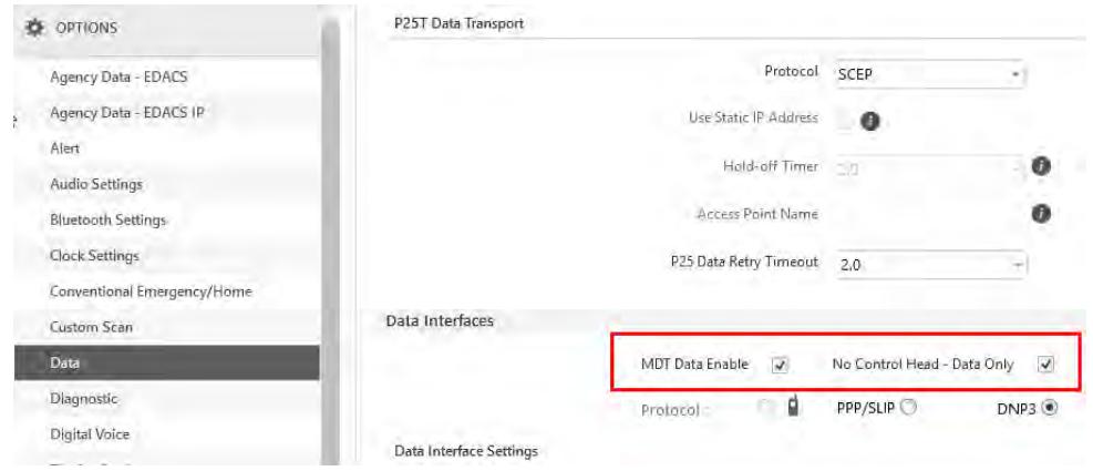
- To limit the impact of voice traffic on the network, set up a voice group set with a single voice group selected with transmit and receive disabled.
a. Navigate to SETS P25 Group. Click Create Set.
No P25 Group Sets
Create Set
b. Name the group (e.g., NO AUDIO).
c. Double-click the group name.
d. Under Group Options, click + to add group.
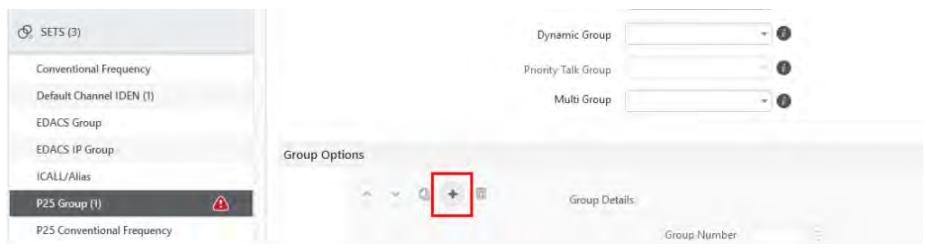
e. Enter a valid Group ID for your P25 Network.
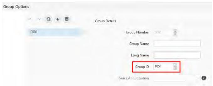
f. Under Group Options, uncheck Transmit, Receive, Calls, and Scan.
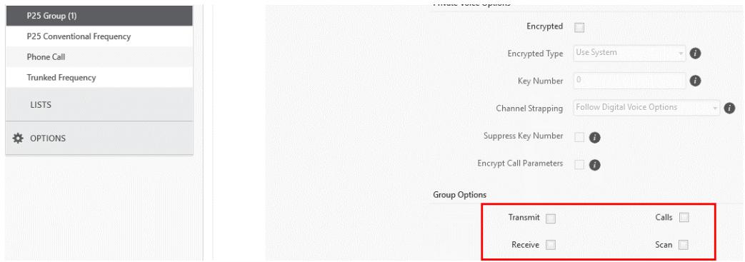
- From the Personality Rail, navigate to SYSTEMS P25 Trunked and select the desired system. Under System Options Sets Options, select the group created in Step 2 from the Group Set drop-down. Leave the Phone Call Set and Individual Call Set fields blank.
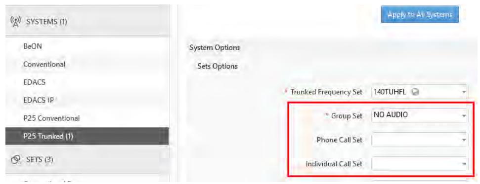
- Save the personality and write the personality to the radio.
7. REFERENCE
7.1 MARINE FREQUENCIES
Refer to Table 7-1: Marine Frequencies for a list of maritime frequencies per United States Coast Guard (USCG).
A radio designated for shipboard use must comply with Federal Communications Commission Rule Part 80. Additional information about operating requirements in the Maritime Services can be obtained from the full text of FCC Rule Part 80 and from the US Coast Guard.
Table 7-1: Marine Frequencies
| NEW CHANNEL NUMBER | OLD CHANNEL NUMBER | SHIP TRANSMIT MHZ | SHIP RECEIVE MHZ | USE |
| 1001 | 01A | 156.050 | 156.050 | Port Operations and Commercial, VTS. Available only in New Orleans / Lower Mississippi area. |
| 1005 | 05A | 156.250 | 156.250 | Port Operations or VTS in the Houston, New Orleans and Seattle areas. |
| 06 | 06 | 156.300 | 156.300 | Intership Safety |
| 1007 | 07A | 156.350 | 156.350 | Commercial. VDSMS |
| 08 | 08 | 156.400 | 156.400 | Commercial (Intership only). VDSMS |
| 09 | 09 | 156.450 | 156.450 | Boater Calling. Commercial and Non-Commercial. VDSMS |
| 10 | 10 | 156.500 | 156.500 | Commercial. VDSMS |
| 11 | 11 | 156.550 | 156.550 | Commercial. VTS in selected areas. VDSMS |
| 12 | 12 | 156.600 | 156.600 | Port Operations. VTS in selected areas. |
| 13 | 13 | 156.650 | 156.650 | Intership Navigation Safety (Bridge-to-bridge). Ships >20m length maintain a listening watch on this channel in US waters. |
| 14 | 14 | 156.700 | 156.700 | Port Operations. VTS in selected areas. |
| 15 | 15 | -- | 156.750 | Environmental (Receive only). Used by Class C EPIRBs. |
| 16 | 16 | 156.800 | 156.800 | International Distress, Safety and Calling. Ships required to carry radio, USCG, and most coast stations maintain a listening watch on this channel. See our Watchkeeping Regulations page. |
| 17 | 17 | 156.850 | 156.850 | State & local govt maritime control |
| 1018 | 18A | 156.900 | 156.900 | Commercial. VDSMS |
| 1019 | 19A | 156.950 | 156.950 | Commercial. VDSMS |
| 20 | 20 | 157.000 | 161.600 | Port Operations (duplex) |
| 1020 | 20A | 157.000 | 157.000 | Port Operations |
| 1021 | 21A | 157.050 | 157.050 | U.S. Coast Guard only |
| 1022 | 22A | 157.100 | 157.100 | Coast Guard Liaison and Maritime Safety Information Broadcasts. Broadcasts announced on channel 16. |
| 1023 | 23A | 157.150 | 157.150 | U.S. Coast Guard only |
| 24 | 24 | 157.200 | 161.800 | Public Correspondence (Marine Operator). VDSMS |
| 25 | 25 | 157.250 | 161.850 | Public Correspondence (Marine Operator). VDSMS |
| 26 | 26 | 157.300 | 161.900 | Public Correspondence (Marine Operator). VDSMS |
| 27 | 27 | 157.350 | 161.950 | Public Correspondence (Marine Operator). VDSMS |
| 28 | 28 | 157.400 | 162.000 | Public Correspondence (Marine Operator). VDSMS |
| 1063 | 63A | 156.175 | 156.175 | Port Operations and Commercial, VTS. Available only in New Orleans / Lower Mississippi area. |
| 1065 | 65A | 156.275 | 156.275 | Port Operations |
| 1066 | 66A | 156.325 | 156.325 | Port Operations |
| 67 | 67 | 156.375 | 156.375 | Commercial. Used for Bridge-to-bridge communications in lower Mississippi River. Intership only. |
| 68 | 68 | 156.425 | 156.425 | Non-Commercial. VDSMS |
| 69 | 69 | 156.475 | 156.475 | Non-Commercial. VDSMS |
| 70 | 70 | 156.525 | 156.525 | Digital Selective Calling (voice communications not allowed) |
| 71 | 71 | 156.575 | 156.575 | Non-Commercial. VDSMS |
| 72 | 72 | 156.625 | 156.625 | Non-Commercial (Intership only). VDSMS |
| 73 | 73 | 156.675 | 156.675 | Port Operations |
| 74 | 74 | 156.725 | 156.725 | Port Operations |
| 77 | 77 | 156.875 | 156.875 | Port Operations (Intership only) |
| 1078 | 78A | 156.925 | 156.925 | Non-Commercial. VDSMS |
| 1079 | 79A | 156.975 | 156.975 | Commercial. Non-Commercial in Great Lakes only. VDSMS |
| 1080 | 80A | 157.025 | 157.025 | Commercial. Non-Commercial in Great Lakes only. VDSMS |
| 1081 | 81A | 157.075 | 157.075 | U.S. Government only - Environmental protection operations. |
| 1082 | 82A | 157.125 | 157.125 | U.S. Government only |
| 1083 | 83A | 157.175 | 157.175 | U.S. Coast Guard only |
| 84 | 84 | 157.225 | 161.825 | Public Correspondence (Marine Operator). VDSMS |
| 85 | 85 | 157.275 | 161.875 | Public Correspondence (Marine Operator). VDSMS |
| 86 | 86 | 157.325 | 161.925 | Public Correspondence (Marine Operator). VDSMS |
| 87 | 87 | 157.375 | 157.375 | Public Correspondence (Marine Operator). VDSMS |
| 88 | 88 | 157.425 | 157.425 | Commercial, Intership only. VDSMS |
| AIS 1 | AIS 1 | 161.975 | 161.975 | Automatic Identification System (AIS) |
| AIS 2 | AIS 2 | 162.025 | 162.025 | Automatic Identification System (AIS) |
7.2 NARROWBANDING
The FCC has mandated that all public safety radios manufactured after January 1, 2013 comply with narrowbanding restrictions. Radios manufactured after the above date will comply with these restrictions. Existing radio personalities that contain frequencies that violate these FCC rules will cause an invalid channel error indication on the radio display. The user will need to change the radio personality to comply with the new rules. Note that there are multiple exceptions to the narrowbanding mandate, including the Marine Frequencies listed in Section 7.1.
8. GLOSSARY
| -A- | |
| AES | Advanced Encryption Standard |
| AES-256 | Advanced Encryption Standard, 256-bit |
| AMBE+2 | Advanced Multi-Band Excitation implementation 2 |
| ANSI | American National Standards Institute |
| ASCII | American Standard Code for Information Interchange |
| -B- | |
| -C- | |
| C | Celsius |
| CA | Canada |
| CDCSS | Continuous Digital Coded Squelch System |
| CH INFO | Channel Information |
| CKR | Common Key References |
| CMB | Continuous Marine Broadcast |
| CTCSS | Continuous Tone Coded Squelch System |
| -D- | |
| DES | Digital Encryption Standard |
| DES-OFB | Digital Encryption Standard Output Feedback |
| DFO | Department Fisheries Ocean |
| DMS | Degrees Minutes Seconds |
| -E- | |
| EDACS | Enhanced Digital Access Communications System |
| EPIRB | Emergency Position-Indicating Radio Beacons |
| -F- | |
| F | Fahrenheit |
| FCC | Federal Communications Commission |
| FM | Frequency Modulation |
| -G- | |
| GHz | Giga (109) Hertz |
| GEOTRANS | Geographic Translator |
| GPS | Global Positioning System |
| -H- | |
| Hz | Hertz |
| HKL | Harris Key Loader |
| -I- | |
| ID | Identification |
| IEEE | Institute of Electrical & Electronics Engineers |
| INTL | International |
| -J- | |
-K-
KEK Key Encryption Key
kHz kilo (10^3) Hertz
KID Key Identification
KMF Key Management Facility
KMM Keypad Mobile Microphone
KMS Key Management System
KS Key Set
KVL Key Variable Loader (Motorola KVL Device)
-L-
LAT/LONG DMS Latitude/Longitude Degrees Minutes Seconds
LAT LONG DD Latitude/Longitude Decimal Degrees
LED Light Emitting Diode
Li-Ion Lithium-Ion
-M-
MHz Megahertz
mm Millimeter
MR Mobile Radio
ms milli (10-3) seconds
-N-
NAC Network Access Code
Ni-MH Nickel Metal Hydride
NOAA National Oceanic and Atmospheric Administration
-0-
OET Office of Engineering and Technology
OTAR Over-The-Air Rekey
-P-
P25 Project 25
POS Position
PRI Priority (Channel)
PTT Push-to-Talk
-Q-
-R-
RF Radio Frequency
RPM2 Radio Personality Manager 2
RSI Radio Set Identifier
RSM Remote Speaker Microphone
RX Receive
-S-
SA Situational Awareness
SMA Subminiature Version A
| -T- | |
| TIA | Telecommunications Industry Association |
| TX | Transmit |
| -U- | |
| UHF | Ultra High Frequency |
| UKEK | Unique Key Encryption Key |
| US | United States |
| USCG | United States Coast Guard |
| UTC | Universal Time Coordinated |
| UTM | Universal Transverse Mercator |
| -V- | |
| VDC | Volts, Direct Current |
| VHF | Very High Frequency |
| VIDA | Voice Interoperability Data Access |
| VTS | Vessel Traffic Service |
| -W- | |
| WEEE | Waste from Electric and Electronic Equipment |
| -X- | |
| -Y- | |
| -Z- | |
9. BASIC TROUBLESHOOTING
9.1 ERROR MESSAGES
This section provides a list of error messages, as well as possible causes and solutions.
Table 9-1: Displayed Error Messages, Reasons, and Resolutions
| SCREEN/MENU | DISPLAYEDERRORMESSAGE | REASON | RESOLUTION |
| Top-LevelScreen | INVALID KEYSTOREZEROI zoneNeded | Corrupt key database orincorrectdatabaseconfiguration. | Zeroize database. |
| BluetoothPairingScreen | PAIRING Failed | Bluetooth pairing failed. | Ensure device is discoverable and attemptto re-pair the device. |
| Channel EditScreen | EDIT Failed | Unable to modify P25Channel. | Power cycle and try again--contactL3Harris if problem persists. |
| Channel EditScreen | INVALID RX FREQUENCY | Entered Rx frequency isinvalid. | Ensure frequency follows band spacingrules. |
| Channel EditScreen | INVALID TX FREQUENCY | Entered Tx frequency isinvalid. | Ensure frequency follows band spacingrules. |
| InstallOperations | INSTALL FAILD | Error during install process. | Transfer file again and reattempt install.Contact L3Harris if problem persists. |
| InstallOperations | INSTALL FAILD | Extraction of compressed filefailed. | Transfer file again and reattempt install.Contact L3Harris if problem persists. |
| InstallOperations | INSTALL FAILD | Removal of existing SWfailed. | Attempt install again and contact L3Harrisif problem persists. |
| Mission PlanIn ProgressScreen | Mission plan activation failed. | Use RPM2 to ensure plan validity.Contact L3Harris if failures persist. | |
| Security Menu | ZEROIZE FAILD | Radio could not zeroize. | Radio problem-power cycle and contactL3Harris if problem persists. |
| Security Menu | NO KEYS TO ZEROIZE | Key database empty. | Nothing to zeroize. |
| UtilitiesMenu | INCORRECT PASSWORD | Maintenance passwordinvalid. | Enter valid maintenance password. |
| Channel InfoScreen | INCORRECT PASSWORD | Channel edit passwordinvalid. | Enter valid channel edit password. |
| Top-LevelScreen | USER REGISTRATIONFAILED FOR... | The user has either entered the wrong values or the user is not in the UAS database. | Check the System ID and User ID. If they are correct, contact your network administrator. |
| Top-LevelScreen | USER PASSWORDFAILEDFOR... | The user has entered a different password then what is in the UAS when password is required. | Re-enter the password. If the error persists, contact your network administrator. |
| Top-LevelScreen | RADIO ESN INVALID FOR... | Contact your network administrator. | |
| Top-LevelScreen | EXCEED ALLOWED USERSFOR... | There are already three radios registered with the same User ID. | Turn off one of these radios or register with a different ID. |
| Top-LevelScreen | PROVISIONING Failed | This failure could be due to bad password or a network issue. | Re-enter the password. If the error persists, contact your network administrator. |
9.2 OTAR ERRORS/INFORMATION
WORKAROUNDS:
- Zeroize.
- Load proper KEK from the L3Harris Key Loader or Motorola KVL.
IF RADIO INDICATES:
- INVALID KEYSTORE ZEROIZE NEEDED - This occurs if the radio's keys were loaded by the L3Harris Key Loader followed by an attempt to load UKEKs with the Key Loader or keys with the Motorola KVL.
Fix by performing workaround 1, followed by 2.
- NO UKEK - Displayed during a zeroize performed from the radio or a zeroize initiated from the KMF.
Fix by performing workaround 2.
- Zeroize Complete - KMF has zeroized the radio.
Fix by performing workaround 2.
- Disabled OTAR Icon (red slash) - OTAR is disabled while in scan, talkaround, emergency, and monitor.
Fix by disabling these features. Icon will be corrected (no red slash).
- Gray OTAR Icon (no red slash) - OTAR has not registered with tower (Conventional or Trunked system).
Fix by verifying proper frequencies.
-
If the radio is turned to the OTAR channel out of range of a conventional tower, and then comes in range after 3 minutes, fix by issuing an OTAR. Rekey, leave and re-enter the OTAR channel.
-
Green OTAR Icon - OTAR is registered, all is well.
-
If update fails, verify you are in range of the tower and the KEK is correct.
-
Blue OTAR Icon - OTAR is attempting to rekey.
-
If rekey fails, verify you are in range of the tower and the KEK is correct.
10. TECHNICAL ASSISTANCE
The Technical Assistance Center's (TAC) resources are available to help with overall system operation, maintenance, upgrades and product support. TAC is the point of contact when answers are needed to technical questions.
Product specialists, with detailed knowledge of product operation, maintenance and repair provide technical support via a toll-free (in North America) telephone number. Support is also available through mail, fax and e-mail.
For more information about technical assistance services, contact your sales representative, or contact the Technical Assistance Center directly:
North America: 1-800-528-7711
International: 1-434-385-2400
Fax: 1-434-455-6712
E-mail: PSPC_tac@l3harris.com
11. WARRANTY
Register this product within 10 days of purchase. Registration validates the warranty coverage and enables L3Harris to contact you in case of any safety notifications issued for this product.
Register on-line at the Customer Care Center webpage https://www.l3harris.com/all-capabilities/pspc-customer-care.
While on the webpage, review the applicable product warranty literature.
APPENDIX A WI-FI PROGRAMMING

CAUTION
Due to numerous issues with discovering and programming radios connected to Enterprise Wireless networks, it is strongly suggested that a single Access Point Wireless network be used for programming radios with RPM2. See Section A.7 for more information.

NOTE
These instructions assume the user has a basic familiarity with Wireless (Wi-Fi) networks, their configuration, and how to connect devices. If you are unfamiliar with the terms and/or procedures mentioned in these instructions, please contact your IT department for help before attempting to configure Wi-Fi programming.

NOTE
For radios to be discoverable on the Wi-Fi network, your wireless router must be configured to allow Multicast (mDNS). This varies by router manufacturer; refer to your router's documentation for specific settings needed to enable Multicast (mDNS).
A.1 OVERVIEW
Perform the following to program a radio over Wi-Fi. For first time setup, see Section A.8.1.
- Configure the Access Point (Section A.2).
- Configure the personality (Section A.3).
- Configure the RPM2 application (Section A.4).
- Put the radio in Wi-Fi Programming Mode (Section A.5).
- Discovery and programming in the RPM2 application (Section A.6).
- Support for Enterprise Wireless Networks (Section A.7).
- Helpful Hints (Section A.8).
A.2 CONFIGURE THE ACCESS POINT
- Setup an Access Point (wireless router) as follows. The bold values provided below are the default values in the personality.
Wireless Networking Name (SSID): harrisradios
Shared Key (Network Password): password
Wireless Authentication/Security Mode (Encryption Type): WPA
WPA and WPA2-PSK are the available Encryption Types in the RPM2 application
- Ensure that the Access Point has Multicast (mDNS) enabled. See the second note at the top of Appendix A for more information.
A.3 CONFIGURE THE PERSONALITY
For a radio to be programmed over Wi-Fi, the active personality on the radio must be configured for connecting with the values that were set in Section A.2. The following steps detail how to configure an existing radio personality.
- In the personality, navigate to OPTIONS Network Configuration.
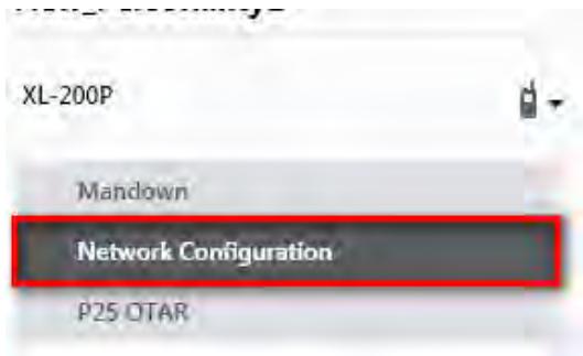
Figure 11-1: Options Network Configuration
- Under the Wi-Fi Configuration section, set the Encryption Type, Network (SSID), and Network Password.

NOTE
XL radios support up to 24 different Wi-Fi networks (SSIDs). These 24 Wi-Fi networks are considered radio administrator approved and Trusted Wi-Fi Networks (TWiN) on which the radios can operate.
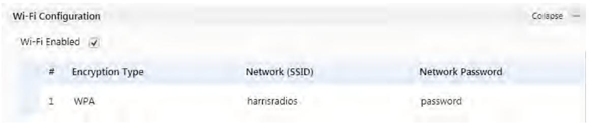
Figure 11-2: Wi-Fi Configuration
- Under Network Service Configuration, the default values can remain the same. If the wireless network is managed by another department, coordinate with them to get it setup correctly.
The Network Discovery Configuration Service Name is a Unique name used by RPM2 and radios to communicate with each other. There is more information about this in Section A.8.2.
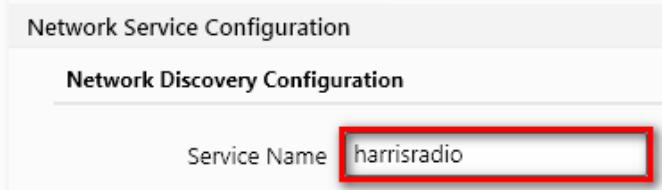
Figure 11-3: Service Name
- After the personality is configured and saved, write it to the radio over USB and then activate it.
A.4 CONFIGURE THE RPM2 APPLICATION
To ensure that RPM2 can discover radios over Wi-Fi, ensure that the Enable Wi-Fi checkbox is checked on the RPM2 Preferences screen as shown in Figure 11-4. This checkbox is unchecked by default.
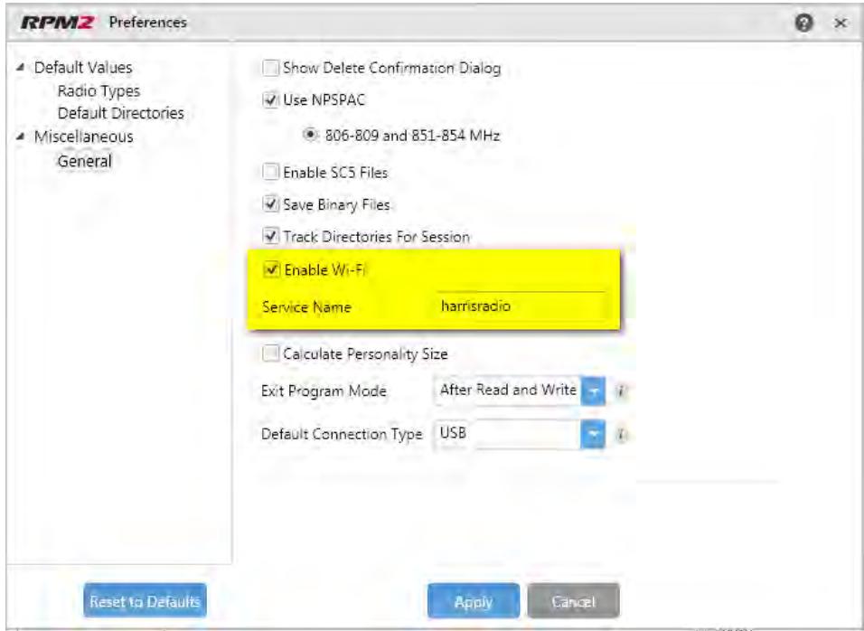
Figure 11-4: Enable Wi-Fi in RPM2
Also, as shown in Figure 11-4, the Service Name must be updated to reference the value in the active personalities for the radios you need to discover. See #3 in Section A.3 and Section A.8.2 for more information.
For default operation using the network as described in Section A.2, no other configuration of the radio or RPM2 is required.
A.5 PUT THE RADIO IN WI-FI PROGRAMMING MODE

NOTE
When using multiple Control Heads, only power on the Control head that is being put into Wi-Fi mode. All other control Heads must remain powered off for the duration of Wi-Fi programming. Upon returning to operational mode and powering up the remaining control heads, they will be updated.
To put the radio in Wi-Fi programming mode:
- Press and hold the menu button while powering on the radio.
- The WIFI INSTALL ACTIVE screen appears on the radio.
- Initially, the radio displays DISCONNECTED. When the IP address is displayed, the radio is available to be programmed.

NOTE
Refer to Section 5.23 for Wi-Fi Client selection information.
A.6 DISCOVERY AND PROGRAMMING IN THE RPM2 APPLICATION
- Start RPM2.
- Disconnect the radio from the programming cable.
- Select the Radio tab and click the Wi-Fi connection button
- When the Wi-Fi connection button is pressed, a "Discovering Wi-Fi Radios" message is displayed for several seconds and the radios connected to that access point with that Service Name populate the connection list.

NOTE
To connect over Wi-Fi, the currently active personality MUST have the correct Wi-Fi parameters. Therefore, care must be taken that all personalities on a given radio have the correct Wi-Fi parameters for the desired network. Otherwise, activation of another personality on the radio will result in the inability to establish a Wi-Fi connection.
- Select a radio or radios and perform the desired action. Only Read Personality, Write Personality, and Load Code are supported over Wi-Fi. See the table below for the supported combinations.
Table 11-1: Wi-Fi Feature Support
| SINGLE RADIO | MULTIPLE RADIOS (UP TO 16) | |
| Read Single Personality | Yes | No |
| Read Multiple Personalities | Yes | No |
| Write Single Personality | Yes | Yes |
| Write Multiple Personalities | No | No |
| Load Single Code File | Yes | Yes |
| Load Multiple Code Files | Yes | Yes |
| Voice Annunciation | No | No |
| Feature Data | Yes | Yes |
| Radio Name | Yes | No |
| Install Splash Screen | Yes | Yes |
- In the Status Panel, all Wi-Fi related actions will have the prefix of "WIFI."
To help in displaying the radios, the "Connection" and "IP Address" columns are sortable.

NOTE
If the Access Point is not configured to the default values from Section A.2 and the active personality in the radio is removed, the radio loses connection to the Access Point and must be connected over USB to write/activate a personality to reconnect to the Access Point.
A.7 RPM2 WI-FI SUPPORT FOR ENTERPRISE NETWORKS.
Enterprise Networks have certain limitations when it comes to Discovering/Programming Radios in RPM2. There is a 4500 second (75 minute) caching affect inherent to implementation with the Cisco® Wi-Fi solution that utilizes the Access Point (AP)/Wireless LAN Controller (WLC) components. Radios remain 'seen' in RPM2 even after the radio leaves Wi-Fi or is turned off. It is cached in RPM2 for 4500 seconds. This issue has only been observed with the Cisco AP and WLC solution; however, other enterprise wireless solutions may observe this caching affect. Operation with a lower tiered Wi-Fi router that does not operate with a WLC will likely not observe this behavior.
Refer to the Network Config Tool Software Release Notes, 14221-3100-8110, for more information.
A.8 HELPFUL HINTS
A.8.1 Initial Setup and Configuration
Since radio discovery is dependent on if Multicast (mDNS) messages are being received by RPM2, it is best to keep things as simple as possible. Here are the suggested steps if this is being setup and configured for the first time.
- Configure the Access Point with the default personality values provided in Section A.2.
- Create a basic personality with a single system, set and channel, write it to the radio and activate it over USB.
- Complete Sections A.4 through A.6.
If the radio was not discovered in RPM2 but an IP address is displayed on the radio screen as seen in Error! Reference source not found., this may mean that the Multicast (mDNS) messages are not making it through the Access Point. Consult the Access Point's manual and make sure that those messages are not being filtered out.
A.8.2 Grouping Radios by Service Name
One benefit of using a unique Service Name is that it allows the user to create logical groupings of radios to reduce the number of radios discovered in RPM2 and help reduce the overhead of keeping track of which radios have been configured.
For example, if there are 100 radios in Wi-Fi programming mode (see Section A.5) with the same Service Name, all 100 radios are displayed in the Radio tab after discovery has been completed. This makes it difficult to select and program multiple radios simultaneously. However, if the Service Name in the active personality on 16 of the radios are set to something unique like "fire1" and the RPM2 application Service Name (see Section A.4) is also updated to "fire1," only those radios with a Service Name of "fire1" are discovered and displayed in the Radio tab.
APPENDIX B CONFIGURING ENCRYPTION
Refer to the following documentation for advanced programming and setup instructions:
OTAR Overview Manual - MM-008069-001
Network Key Manager Installation and Configuration Manual - MM-008070-001
UAS Key Management Application Manual - MM-008068-001
Key Manager Key Admin Overview and Operation Manual - MM1000019423
Key Manager Key Loader Overview and Operation Manual - MM1000019424
Motorola® KVL User's Guide
B.1 CREATE KEYS USING L3HARRIS KEY ADMIN
L3Harris Key Admin is part of the L3Harris Key Manager and is used by the Crypto Officer (CO). The CO creates a Master Set of keys from which a Distribution Set is produced. Using the Key Admin software, the CO can save keys into Distribution key files for technicians to use in radios.
- Select Start Harris Key Manager Harris Key Admin.
- Select New Master Set, Open, or Import from Security Device. Refer to the Key Admin online help for more information on creating keys.
- When finished, create a Distribution Key File. A Distribution Key File is used with Key Loader to load key sets into the radio and cannot be edited. Refer to the Key Admin online help for more information on creating the Distribution Key File.
B.2 LOAD ENCRYPTION KEYS
B.2.1 Load UKEKS with Key Loader and RPM2 (for OTAR-Enabled Systems)
UKEKs are loaded into L3Harris OTAR-enabled radios using the Key Loader application. Key Loader is a part of Key Manager.
To load encryption keys:
- Obtain the UKEK file and Storage Location Number (SLN) Binding Report information from the Crypto Officer (CO).

Both AES and DES UKEKs can be contained within the same UKEK file.
- If not already on, power-up the PC on which RPM2 and Key Loader are installed.
- Connect the radio to the PC using the USB programming cable.
- Load the UKEK file from the Crypto Officer onto the PC.
- Run the RPM2 application and setup the radio's Personality according the SLN Binding Report information.
-
Setup the talk groups and the SLN mappings (Talk Group ID to SLN). This includes mapping SLNs to the "System" keys (PSTN, All Call, etc.).
-
In RPM2, select P25 OPTIONS P25 OTAR/Keystores and set the following, referring to the RPM2 online help as necessary:
a. Click Create to add a Keystore or edit the Default Keystore.
b. Check Enable OTAR Options.
c. Enter the OTAR Message Number Period (MNP) as defined by the System Administrator.
d. Enter the radio's Individual RSI (from the SLN Bindings Report).
e. Enter the KMF's RSI (from the SLN Bindings Report).
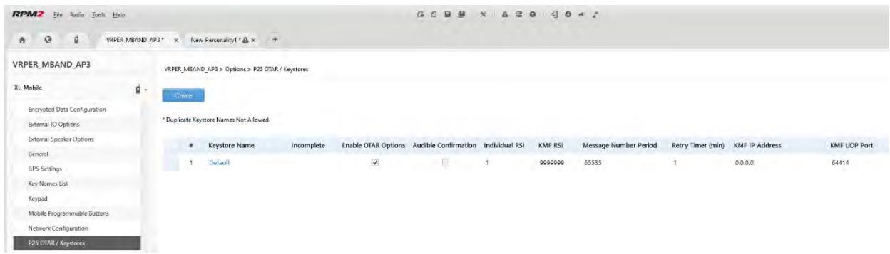
- Program the Personality to the radio.
- Run the Key Loader application.
- Open the UKEK file loaded in step 4.
- Select the Target Device type and click the Load button.
- The Key Loader reads the target device's identifying information, retrieves a UKEK of the proper algorithm type from the UKEK file, and downloads the UKEK to the target device at the proper SLN and keyset with the proper key ID.
- Click button to exit the Key Loader application. New UKEKs have are loaded and the radio is now ready to accept TEKs via OTAR with the trunked radio network.
B.2.2 Load Keys Using Harris Key Loader
Harris Key Loader is part of Harris Key Manager and can be used by the Crypto Officer or Technician to load the keys into the radio.
Refer to the Harris Key Loader online help if additional information is required when performing this procedure.
- Connect the radio to the PC using the USB programming cable.
- Power on the radio, if not already.
- Select Start Harris Key Manager Harris Key Loader.
- At the Key Loader Welcome screen, click Next.
- Select Load a Distribution Set into one or more devices.
- Click Next.
-
Browse to the Key File and enter the password.
-
Click Next to validate the password and continue. If the password is incorrect, the screen will display an error message.
- Ensure USB is selected in the drop-down and click Next.
- Select the radio from the drop-down and click Load.
- Click Finish.
B.2.3 Load Keys with Motorola KVL
- Disconnect the microphone from the microphone connector on the control head (see Figure 4-1).
- Connect the KVL cable to the microphone connector.
- From the radio's SECURITY menu, select KVL MODE to interact with the KVL.
- The KVL Mode screen is displayed.
- While in the KVL Mode, the KVL can be used to load keys, read keys, etc., from the XL-Mobile.
- While a KVL key transfer or read is in progress, the KVL Transfer in Progress screen is displayed.
- When the key transfer and loading is complete, the KVL Transfer Complete screen is displayed.
- Success and failure messages are shown on the KVL device's screen. Additional keys can be loaded or read from the XL-Mobile while the screen shows KVL MODE ACTIVE - TRANSFER COMPLETE.
- Once finished loading or reading keys from the XL-Mobile, press BACK or the blue HOME button to exit KVL Mode.
- Disconnect the KVL cable and reattach the USB Microphone to the Control Head.
B.2.4 Link-Layer Authentication (LLA) Keyloading with Motorola KVL
In XLP R16A and later, LLA Keys (i.e., Radio Authentication Keys) can be loaded using a KVL-5000 or KVL-4000. The LLA feature must be enabled to utilize this feature.
- Connect the radio to the KVL device using cable 12082-0400-A1.
- Put the radio into KVL LLA Mode:
a. Press the Menu button.
b. Navigate to the SECURITY menu.
c. Scroll up or down to highlight KVL LLA and press the Select Button
- The Radio will indicate that KVL LLA Mode is active.
- Once KVL LLA Mode is activated, the KVL device can be used to provision the radio with LLA keys. The radio will remain in KVL LLA Mode until the user exits this state.
B.3 PROTECTED KEYS
The Protected Keys feature transfers P25 Voice Keys, from Harris Key Loader to the radio, that have been wrapped (AES) or encrypted (DES) with Key Protection Keys (KPKs). KPKs are unprotected Key Encryption Keys (KEKs). The KPKs need to be loaded into the radio before the Protected Keys are loaded. Once loaded into the radio, the KPKs are used to unwrap (AES) or decrypt (DES) the Protected Keys.
The radio must be placed into the key loading mode (see Section B.2.2) in order to accept the KPKs and P25 Voice Keys.
About L3Harris Technologies
L3Harris Technologies is an agile global aerospace and defense technology innovator, delivering end-to-end solutions that meet customers' mission-critical needs. The company provides advanced defense and commercial technologies across air, land, sea, space and cyber domains.

- XL-85M Series Mobile Radios
- L3Harris Technologies, Inc.
- ACKNOWLEDGEMENT
- CREDITS
- NOTICE!
- TABLE OF CONTENTS
- Section
- Page
- REGULATORY AND SAFETY INFORMATION 8
- RENSEIGNEMENTS SUR LA REGLEMENTATION ET SECURITE 16
- ADVANCED OPERATIONS 56
- PROGRAMMING
- .75
- 7.REFERENCE
- .83
- GLOSSARY...
- .85
- BASIC TROUBLESHOOTING
- .88
- TECHNICAL ASSISTANCE.
- .91
- WARRANTY
- APPENDIX A WI-FI PROGRAMMING
- .92
- APPENDIX B CONFIGURING ENCRYPTION.
- LIST OF FIGURES
- LIST OF TABLES
- REGULATORY AND SAFETY INFORMATION
- SAFETY SYMBOL CONVENTIONS
- RF ENERGY EXPOSURE AWARENESS AND CONTROL INFORMATION FOR FCC OCCUPATIONAL USE REQUIREMENTS
- FEDERAL COMMUNICATIONS COMMISSION REGULATIONS
- COMPLIANCE WITH RF EXPOSURE STANDARDS
- Mobile Antennas
- Approved Accessories
- Contact Information
- REGULATORY APPROVALS
- Applicable Type Acceptance/Certification Numbers
- FCC Part 15
- ISED Canada
- OCCUPATIONAL SAFETY GUIDELINES AND SAFETY TRAINING INFORMATION
- COMMON HAZARDS
- SAFE DRIVING RECOMMENDATIONS
- OPERATING RULES AND REGULATIONS
- OPERATING TIPS
- CITIZENS BAND OPERATION IN AUSTRALIA/NEW ZEALAND
- RENSEIGNEMENTS SUR LA RÉGLEMENTATION ET SÉCURITÉ
- CONVENTIONS SUR LES SYMBOLES DE SECURITE
- CONFORMITE AUX NORMES D'EXPOSITION AUX RF
- XL-CH2 CONTROL HEAD
- KEYPAD MOBILE MICROPHONE (KMM)
- CLEANING
- OPTIONS AND ACCESSORIES
- RELATED PUBLICATIONS
- BASIC OPERATION
- RADIO CONTROLS
- BEFORE FIRST USE
- POWER ON AND SET VOLUME
- VIDA® ID
- User Login
- Provisioning
- RADIO DISPLAYS
- STATUS MESSAGES
- PREDEFINED MENU LAYOUTS
- MENU
- ALERT TONES
- SELECT ZONE/System
- Or
- SELECT GROUP/CHANNEL
- Numeric Channel Entry
- LOCK/UNLOCK KEYPAD
- GROUP CALLS
- Transmit a Group Call
- Receive a Group Call
- INDIVIDUAL CALLS
- Transmit an Individual Call
- Receiving an Individual Call
- USER PROFILES
- NOISE CANCELLATION
- Enable Noise Cancellation
- Using Noise Cancellation
- The Effect of Distance from the Microphone
- Voice Versus Noise Reference Microphone
- ENABLE/DISABLE ENCRYPTION
- CHANNEL GUARD (ANALOG CONVENTIONAL ONLY)
- USE TALKAROUND TO BYPASS REPEATER (ANALOG AND P25 CONVENTIONAL ONLY)
- Enable/Disable Type 99
- Disable After PTT
- Auto Reset
- CALL ALERT (PAGE)
- Send Alert
- Receive Alert
- TELEPHONE INTERCONNECT
- DTMF
- START SCAN
- STOP SCAN
- MONITOR AND SQUEELCH TYPES (CONVENTIONAL ONLY)
- NUISANCE DELETE
- FAILSOFT
- Conventional Failsoft (EDACS)
- Failsoft (P25 Trunked)
- Declaring an Emergency Call
- Receiving an Emergency Call
- Stealth Emergency
- MDC-1200 (ANALOG CONVENTIONAL ONLY)
- Normal PTT Operation
- MDC PTT ID Receive Handling
- Emergency Declaration
- MULTIGROUP (P25 TRUNKING ONLY)
- BEON OPERATION
- IGNITION SHUT-OFF TIMER
- ADVANCED OPERATIONS
- VIEW/CHANGE PERSONALITIES
- View Personalities
- Change Active Personality
- SITUATIONAL AWARENESS (SA) - P25 CONVENTIONAL ONLY
- USER DEFINED ZONES
- CHINFO MENU
- CONVENTIONAL OR P25 CHANNELS ONLY:
- AUDIO SETTINGS
- DISPLAY SETTINGS
- GPS SETTINGS
- POSITION INFO
- BLUETOOTH
- Enable Bluetooth
- Pair Devices
- CLOCK SETTINGS
- SELECT LANGUAGE
- SET UP SCAN
- Default, Priority 1, and Priority 2 Channels
- Default Channel
- Priority 1 Channel
- Priority 2 Channel
- Trunked/Conventional Scanning
- Vote Scan (Analog and P25 Conventional Only)
- Edit Scan List
- Set or Remove Priority 1 and Priority 2 Channels
- Custom Scan Lists
- Create Custom Scan List
- Wide Area System Scan (P25 Trunked)
- Site Lock
- RADIO STATUS
- RADIOMESSAGE
- RADIO TEXTLINK
- RadioTextLinkMessages
- RadioTextLink Forms
- View Received Messages
- FAULTS/ALERTS
- TONE ENCODE
- ENCRYPTION
- Zeroize Keys from Radio
- Protected Keys
- Global Encryption
- Select Keyset
- View Key List
- Delete Individual Keys
- OTAR Configuration
- P25 CONVENTIONAL FALLBACK
- STEALTH MODE
- EMERGENCY CHECK-IN TIMER
- WI-FI CLIENT SELECTION
- EXTERNAL SPEAKER
- L3HARRIS DEVICE MANAGEMENT
- PROGRAMMING VIA RPM2
- WI-FI PROGRAMMING
- EDIT CHANNEL (ANALOG AND P25 CONVENTIONAL ONLY)
- Only authorized users should attempt channel editing.
- OTAP
- PROGRAMMABLE BUTTONS
- PROGRAMMABLE ICONS
- DATA ONLY CONFIGURATION
- REFERENCE
- MARINE FREQUENCIES
- NARROWBANDING
- GLOSSARY
- -K-
- -L-
- -M-
- -N-
- -0-
- -P-
- -Q-
- -R-
- -S-
- ERROR MESSAGES
- OTAR ERRORS/INFORMATION
- WORKAROUNDS:
- IF RADIO INDICATES:
- TECHNICAL ASSISTANCE
- A.1 OVERVIEW
- A.2 CONFIGURE THE ACCESS POINT
- A.3 CONFIGURE THE PERSONALITY
- A.4 CONFIGURE THE RPM2 APPLICATION
- A.5 PUT THE RADIO IN WI-FI PROGRAMMING MODE
- A.6 DISCOVERY AND PROGRAMMING IN THE RPM2 APPLICATION
- A.7 RPM2 WI-FI SUPPORT FOR ENTERPRISE NETWORKS.
- A.8 HELPFUL HINTS
- A.8.1 Initial Setup and Configuration
- A.8.2 Grouping Radios by Service Name
- APPENDIX B CONFIGURING ENCRYPTION
- B.1 CREATE KEYS USING L3HARRIS KEY ADMIN
- B.2 LOAD ENCRYPTION KEYS
- B.2.1 Load UKEKS with Key Loader and RPM2 (for OTAR-Enabled Systems)
- B.2.2 Load Keys Using Harris Key Loader
- B.2.3 Load Keys with Motorola KVL
- B.2.4 Link-Layer Authentication (LLA) Keyloading with Motorola KVL
- B.3 PROTECTED KEYS
- About L3Harris Technologies
Brand : L3Harris
Model : XL-85M
Category : Mobile radio