AW-HN38H - PTZ Camera PANASONIC - Free user manual and instructions
Find the device manual for free AW-HN38H PANASONIC in PDF.

User questions about AW-HN38H PANASONIC
0 question about this device. Answer the ones you know or ask your own.
Ask a new question about this device
Download the instructions for your PTZ Camera in PDF format for free! Find your manual AW-HN38H - PANASONIC and take your electronic device back in hand. On this page are published all the documents necessary for the use of your device. AW-HN38H by PANASONIC.
USER MANUAL AW-HN38H PANASONIC
Operating Instructions
Installation Instructions provided
HD Integrated Camera
Model No. AW-HE38HWPC
Model No. AW-HE38HKPC
Model No. AW-HE38HWE
Model No. AW-HE38HKE

HOMI
ENGLISH
Before using this product, be sure to read "Read this first!" (pages 5, 27 to 31).
This manual contains information excerpted from the Operating Instructions and the Installation Instructions.
For more information, please visit the Panasonic website (http://pro-av.panasonic.net/manual/en/index.html), and refer to the Operating Instruction (PDF).
FRANÇAIS
Before operating this product, please read the instructions carefully and save this manual for future use.
| Български | Посетete следnia уебаит отоною поформения за бezопасостта и вожни у vectомлени за пroduкту. | Latviešu | Lai igūtu informāciju par drošību un skāṭùv svarfīgus pazićojumus par šo produktu, apmeklējiet tālák norādīto tîmekla viétrni. |
| Hrvatski | Za sigurnosne informaciè i važne obavijesti o proizvodu posjetite sljedću internetsku stranicu. | Lietuviç | Jei reikia saugos informacijos ir svarbiŋ pranešimi ajpie gaminj, apsilankykite toliau nurodytoje svetainéje. |
| Čeština | Na následujićim webu najdete bezpečnostné informace a duležité poznámky k totomuto produktu. | Polski | Informace o bezpieczeniстwie i važne informace o produktie znajduja są w ponižszej witrynie internetowej. |
| Dansk | Besøg følgende webside for sikkerhedsinformation og vigtige bemærkninger vedrørende produit. | Portuguès | Consulte o seguinete website para as informações de segurança e importantes notifications sobre o produits. |
| Nederlands | Ga waar de volgende website voor veiligheidsinformatie en belangrijke meldingen over het product. | Română | Vizitaşi ursmǎtoarea pagină web pentru informati de securitate și notificari很重要的 parte du privire la produs. |
| Eesti | Toodet puudutava ohutusteabe ja oluliste märkuste saamiseks kūlastage järgmist veebilehte. | ||
| Suomi | Käy seuraavalla verkkosivulla saadaksesi turvallisuustietoja ja tärkeitä tietoja liittyen laitteeseen. | Slovensky | Pre bezpečnostné informácie a duležité oznámenia suviisiac s produktom navstíte túto webovú stránku. |
| Еλληνίκα | Гι πληροφορίες σχέτικά με θέματα ασφάλείας και σημαντικές εἰδότουποίεις του αφορουν το τροίόν σας, ᵠΤΙΟΚΕΦΤΕΤΕΤΟ IGTÓΤΟ TΤΟ ΑΚΟλουθέι. | Slovensčina | Za varnostne informaciè in pomembna obvestila v zvezi z izdelkom obišcite naslednje spltno mesto. |
| Magyar | A termékkel capcsolatos biztonsági információktés fontos értesít sékét látogasson el az alábbi webboldalra. | Svenska | Besök fålande webblats für sakerhetsinformation och viktiga meddelanden om Produkten. |
http://pro-av.panasonic.net/manual/en/index.html
Trademarks and registered trademarks
- Microsoft®, Windows®, Windows® 7, Windows® 8, Windows® 8.1, Internet Explorer® and ActiveX® are either registered trademarks or trademarks of Microsoft Corporation in the United States and other countries.
- Intel® and Intel® Core™ are trademarks or registered trademarks of Intel Corporation in the United States and other countries.
- Adobe® and Reader® are either registered trademarks or trademarks of Adobe Systems Incorporated in the United States and/or other countries.
- HDMI, the HDMI logo and High-Definition Multimedia Interface are the trademarks or registered trademarks of HDMI Licensing LLC in the United States and other countries.
- microSDXC Logo is a trademark of SD-3C, LLC.
- Apple, Mac, OS X, iPhone, iPod Touch, iPad, and Safari are registered trademarks of Apple Inc., in the United States and other countries.
- Android™ is a trademark of Google Inc.
- Other names of companies and products contained in these Operating Instructions may be trademarks or registered trademarks of their respective owners.
About copyright and licence
Distributing, copying, disassembling, reverse compiling, reverse engineering, and also exporting in violation of export laws of the software provided with the unit are expressly prohibited.
This product incorporates the following software:
(1) the software developed independently by or for Panasonic Corporation,
(2) the software owned by third party and licensed to Panasonic Corporation,
(3) the software licensed under the GNU General Public License, Version 2.0 (GPL V2.0),
(4) the software licensed under the GNU LESSER General Public License, Version 2.1 (LGPL V2.1), and/or
(5) open source software other than the software licensed under the GPL V2.0 and/or LGPL V2.1.
The software categorized as (3) - (5) are distributed in the hope that it will be useful, but WITHOUT ANY WARRANTY, without even the implied warranty of MERCHANTABILITY or FITNESS FOR A PARTICULAR PURPOSE.
For details, refer to the license conditions that appear when the operation described on P. 106 of the
At least three (3) years from delivery of this product, Panasonic will give to any third party who contacts us at the contact information provided below, for a charge no more than our cost of physically performing source code distribution, a complete machine-readable copy of the corresponding source code covered under GPL V2.0 or LGPL V2.1, as well as the respective copyright notice thereof.
Contact Information: oss-cd-request@gg.jp.panasonic.com
The source code and the copyright notice are also available for free in our website below.
https://panasonic.net/cns/oss/index.html
Abbreviations
The following abbreviations are used in this manual.
- Microsoft® Windows® 7 Professional SP1 32/64-bit is abbreviated to "Windows 7".
- Microsoft® Windows® 8 Pro 32/64-bit is abbreviated to "Windows 8".
- Microsoft® Windows® 8.1 Pro 32/64-bit is abbreviated to "Windows 8.1".
- Windows® Internet Explorer® 8.0, Windows® Internet Explorer® 9.0, Windows® Internet Explorer® 10.0 and Windows® Internet Explorer® 11.0 are abbreviated to "Internet Explorer".
For the purposes of this manual, the model numbers of the units are given as listed in the table below.
| Model number of unit | Model number given in manual |
| AW-HE38HWPC, AW-HE38HKPC, AW-HE38HWE, AW-HE38HKE | AW-HE38 |
| AW-HS50N | AW-HS50 |
| AW-HS50E | |
| AW-RP50N | AW-RP50 |
| AW-RP50E | |
| AW-RP120G | AW-RP120 |
| AK-HRP200G | AK-HRP200 |
Illustrations and screen displays featured in the manual
- What is shown in the manual's illustrations and screen displays may differ from how it is actually appears.
- The screenshots are used in accordance with the guidelines of Microsoft Corporation.
Installation Instructions
Read this first! 5
Installation precautions 6
How to install and connect the unit. 8
When using the WV-Q105A (optional accessory) 12
Removing the camera. 14
Stand-alone installation (when the mount bracket is going to be used).....15
Stand-alone installation (when the mount bracket is not going to be used) 17
When installing the unit on a desktop 17
When mounting the unit on a tripod 17
Connections 18
Connecting an NDIJHX compatible switcher 18
Connecting a controller (AW-RP50/AW-RP120)
(IP connection example) 19
System example 1 (connection with commercially available controller, RS-232C daisy-chain connection)............20
System example 2 (connection with commercially available controller, RS-422 connection)................................21
System example 3 (serial control) 22
System example 4 (IP control) 23
System example 5 (infrared output connection) 24
System example 6 (IP image transmission, PoE+)......24
System example 7 (USB connection, Web camera)......25
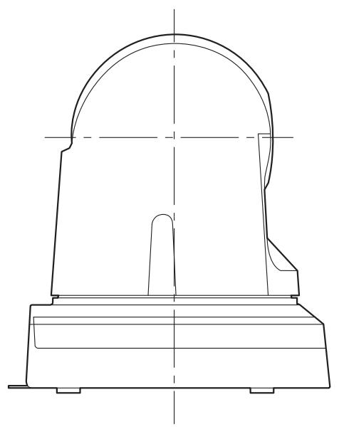
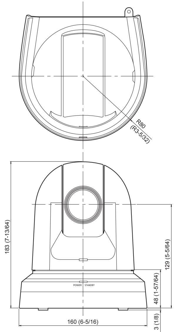
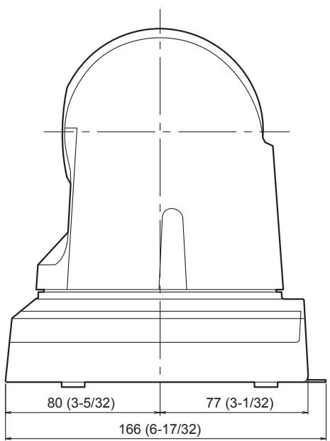
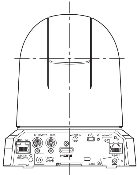
Appearance 26
Operating Instructions
Read this first! (For AW-HE38HWPC, AW-HE38HKPC) 27
Read this first! (For AW-HE38HWE, AW-HE38HKE)....29
Before use 32 Overview 32
Required personal computer environment 32
Disclaimer of warranty 33
Network security 33
Characteristics 34
Controller supported. 36
Accessories 36
Optional accessories 36
Operating precautions 37
Concerning the wireless remote control (optional accessory) 39
Parts and their functions 40
Camera unit. 40
Wireless remote controller (optional accessory) 43
Setting the remote control IDs. 45
Network settings [When using Windows] 46 Use the Easy IP Setup Software to establish the unit's settings 46
Installing the plug-in viewer software 47
User authentication. 48
Troubleshooting 49
Specifications. 51
Index 55
WARNING:
To prevent injury, this apparatus must be securely attached to the floor/wall in accordance with the installation instructions.
WARNING:
Installation should only be performed by qualified installation personnel.
Improper installation may result in the entire apparatus falling down and causing injury.
CAUTION:
This camera intended for use only with the Mount Bracket enclosed with the unit and Panasonic Direct Ceiling Mount Bracket, WV-Q105A.
Use with other apparatus is capable of resulting in instability causing possible injury.

indicates safety information.
Panasonic does not accept any responsibility for accident or damage during installation if procedure in this manual is not followed.
To installation personnel
Read the "Installation Instructions" thoroughly and then perform the operation correctly and safely. Also, always read the "Read this first!" (page 5) of this manual as they contain important information.
After the installation, give the "Operating Instructions
Ensure that the installation work complies with the technical standards governing electrical equipment.
The unit is for indoor use only.
It cannot be used outdoors.
Avoid installation in a location where the unit will be exposed to direct sunlight for extended periods or near a cooling or heating appliance.
Otherwise, deformation, discoloration, malfunctioning and/or problems in operation may result. Operate the unit where it will not be splashed or sprayed by water.
Use the unit with an installation where the unit is suspended from an overhead surface or with a stand-alone installation.
Do not use the unit on its side or tilted at an angle.
Notes
- Be absolutely sure to use the four bracket mounting screws (M4) for mounting the mount bracket. These are supplied with the unit. Do not use wood screws, nails, etc. In the case of a concrete ceiling, secure the unit using anchor bolts (for M4) or AY plug bolts (for M4).
Recommended clamping torque M4:1.47 N·m {15 kgf·cm}
- The withdrawal strength of the mounting location for each screw must be at least 196 N 20kgf .
- When mounting the unit on a ceiling made of plasterboard, for instance, if it is not strong enough to support its weight, either reinforce the ceiling adequately or use the WV-Q105A direct ceiling mount bracket, which is sold separately.
- When using a mount bracket which is sold separately, read the handling instructions.
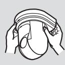
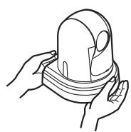
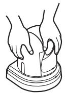
- Do not hold the camera head while undertaking the installation work. Doing so may cause malfunctioning.
Correct Incorrect

Desktop installation
Correct Incorrect

Hanging installation
Concerning the installation location
Install the unit in a stable location which will not be susceptible to shaking. If the unit is installed in a location which is susceptible to shaking, this will cause the unit's images to shake in turn.
Install the unit after conferring in detail with your dealer. Install the unit on a ceiling that is strong enough (such as a concrete ceiling).
If the unit is to be installed on a ceiling which is not strong enough, reinforce the ceiling sufficiently first.
Do not install or use the unit in the following kinds of locations.
- On walls (where the unit would be installed sideways)
- In locations (including places such as under the eaves of a building) where the unit would be directly exposed to rain or water
- In locations such as kitchens where there are high concentrations of steam and grease
- In outdoor locations or hot places where the temperature will exceed 40^ C ( 104^ F )
- In cold locations where the temperature will drop below 0^ C (32°F)
- In locations where the humidity will exceed 90%
- In locations where chemicals are used such as near swimming pools
- At sea, in coastal areas or in locations where corrosive gases are emitted
- In locations where radiation, X-rays, or strong radio waves or magnetic fields are generated
- In locations where the unit would be subject to a great deal of vibration such as on board a vehicle or ship (the unit is not designed to be used in vehicles)
- In locations where the temperature is subject to sudden changes such as near the air outlet of an air conditioner or near a door which allows the outside air to come in
What to avoid to ensure that the unit will perform stably over a prolonged period
- Using the unit for a prolonged period in a location with high temperature and humidity levels will cause its parts to deteriorate and shorten its service life.
- Ensure that a cooling unit or heating unit will not blow any air directly toward the installation location.
| AW-HE38 main unit | Mounting conditions | |||||
| Applicable mount bracket | Mounting onto the ceiling | |||||
| Mass | Model No. | Mass | Mounting | Recommended screws | No. of screws | Minimum withdrawal strength (per screw) |
| Approx. 1.5 kg [3.30 lb] | Direct mount (supplied accessory) | Approx. 0.23 kg [0.51 lb] | Hanging/Desktop | M4 screws (supplied accessory) | 4 | 196 N (20 kgf) • Ensure that the mounting strength can support a weight that is at least five times the total mass of the equipment, including the camera's main unit. |
| WV-Q105A (optional accessory) | Approx. 0.15 kg [0.33 lb] | For ceiling | M4 screws (supplied with the WV-Q105A) | 4 | ||
Be absolutely sure to use the specified brackets and screws to install the camera.
- Do not mount the unit by employing any methods other than those specified.
- Do not remodel the mounting bracket or mounting screws provided with the unit.
Before installation, always disconnect the power plug
When installing, always use the supplied components.
Do not disassemble or modify the wall mount adaptor.
Tightening up the mounting screws
- Tighten up the screws and bolts securely to the degree that is appropriate for each of the materials used in the mounting location and structures.
- After tightening up the screws and bolts, check that there is no unsteadiness and that the parts have been tightened securely.
- Use the specified tools and tighten the screws firmly.
- Tighten up the screws using the specified torque driver. Do not use electrical drivers or impact drivers.
When the unit is no longer going to be used, do not leave it lying around, but be absolutely sure to remove it properly.
For details on how to remove the unit, refer to “Removing the camera” (page 14).
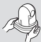
When installing, transferring or disposing of the unit, be absolutely sure to hold it by its pedestal area.
Problems may result if the camera head is held or rotated.
Do not attach a filter, hood, extender or other parts to the unit.
Use the dedicated AC adaptor and power cable provided with the unit.
Connect the AC adaptor and power cable to the power inlet securely.
Installing the AC adaptor
- Do not place the adaptor directly onto a ceiling panel or other such surface.
Extreme danger is posed when water has collected on the surface as a result of leaking rain, for instance.
Secure the adaptor firmly to the bottom or other surface of a reinforcing member made of channel steel where dust and other foreign matter will not accumulate.
(Refer to page 12.)
- Secure the adaptor firmly so that there will be no chance that it will fall off or fall down.
Secure it using a strength which can withstand the mass of the AC adaptor.
Install the accessory AC adaptor near the main power outlet, and position it in such a way that its power plug can be plugged into and unplugged from the outlet easily.
When connecting the AC adaptor to a power outlet on the ceiling or on any other surface where dust may collect, wipe off the dust on the power plug at periodic intervals as an anti-tracking measure.
Power switch
The unit does not have a power switch. The power turns on when its power plug is connected to a power outlet. When the power is turned on, the pan, tilt, zoom and focusing operations are performed. Before proceeding with maintenance, be absolutely sure to disconnect the power plug from the power outlet.
Connecting the power cable
Be absolutely sure to connect the power cable of the AC adaptor through a circuit breaker using one of the following methods.
(1) Connect the power cable through a power control unit.
(2) Connect the power cable to a circuit breaker in a power distribution panel with a contact distance of 3.0mm (1/8 inches) or more.
Use a circuit breaker which is capable of shutting off all the poles of the main power supply with the exception of the protective ground conductor.
(3) Install the AC adaptor near the power outlet, and connect it through the power plug.
If there is a possibility of noise interference
Either wire the cables so that the power cable (ceiling light cord) of AC 100V^ [AC 220V^* ] or more, and the signal cable are placed at least 1 meter (3.3 ft) apart. Alternatively run each cable through its own metal conduit. (The metal conduits must be grounded.)
- : For AW-HE38HWPC, AW-HE38HKPC
**: For AW-HE38HWE, AW-HE38HKE
Radio signal interference
If the unit is positioned near a TV or radio transmitting antenna or a strong electrical field or magnetic field (such as that generated by a motor, transformer or power lines), its images may be distorted and/or the images may be affected by noise.
When connecting the cables, ensure that the connector areas will not be subject to any load.
Doing so may cause malfunctioning.
Allowing the generated heat to escape
The unit allows the heat generated inside to escape from its surfaces.
Do not install the unit in a location where it will be surrounded by walls or other surfaces and where heat will be trapped. In addition, the heat is dissipated to the bottom panel which will warm up over time: This is normal and not indicative of any trouble.
PoE+ power supplies
Use a PoE+ (IEEE802.3at) compatible hub or power supply device.
Be absolutely sure to read through the "Read this first!" (page 5) and "Installation precautions" (pages 6 to 7).
The procedure given here is for the kind of installation where the unit is suspended from an overhead surface, but the same steps are followed for a stand-alone installation.
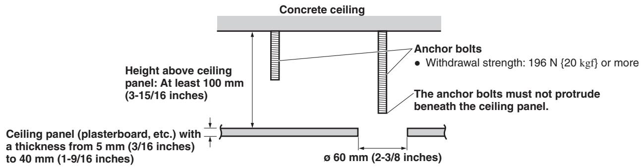
If the ceiling panel is not strong enough to bear the unit's weight, use the kind of mount bracket that is supported by anchor bolts between the concrete ceiling and ceiling panel. The unit supports the WV-Q105A direct ceiling mount bracket which is used solely for combination cameras. Use this bracket to install the unit. (See page 12.) In a case like this, the holes ( 60 mm [ø 2-3/8 inches]) for installing the direct ceiling mount bracket on the ceiling must be drilled in the ceiling panel. It is also recommended that you provide an inspection space or opening for access purposes in the area near where the equipment is installed in order to facilitate installation and the wiring connections work. See page 36 for details of the accessories.
1 Check the mounting space.
- Refer to the illustration, and determine where the unit is to be installed and in which direction it should be mounted. Factor in the unit mounting area and include space for the wires extending from its rear panel.
- The asterisk () in the illustration marks the position and dimensions of the hole for mounting the mount bracket.
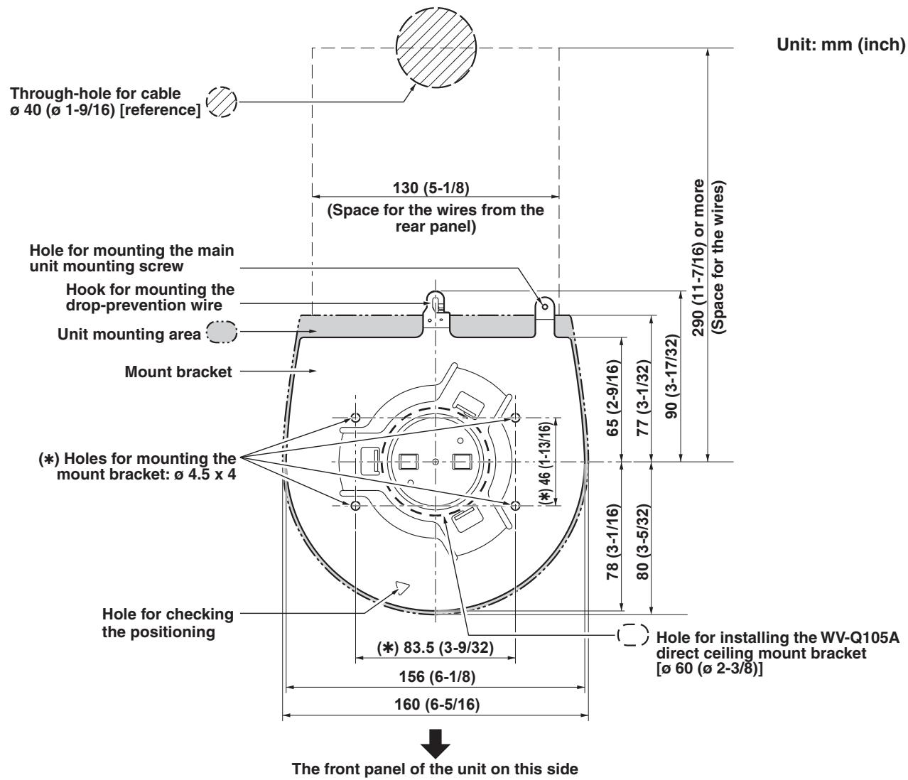
Notes
- Make connections for each cable within the ceiling beforehand, and pass the cables through a cable-routing hole in preparation for making connections for and installing the unit.
- For a power outlet which is used on the ceiling, be absolutely sure to take measures to deal with the tracking that may be caused by the accumulation of dust and other foreign matter.
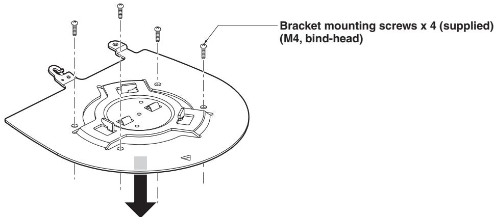
2 Mount the mount bracket onto the installation surface.
- Use the bracket mounting screws [M4, bind-head: 10 mm (13/32 inches) long] supplied with the unit.
- For proper clamping torque, securely attach the screws using the specified tools.
| Screw diameter | Clamping torque |
| M4 | 1.47 N·m {15 kgf·cm} |
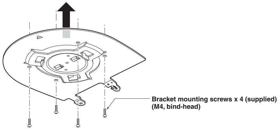
Note
- Use only the screws supplied with the unit. Do not use any other screws such as wood screws, nails, etc.
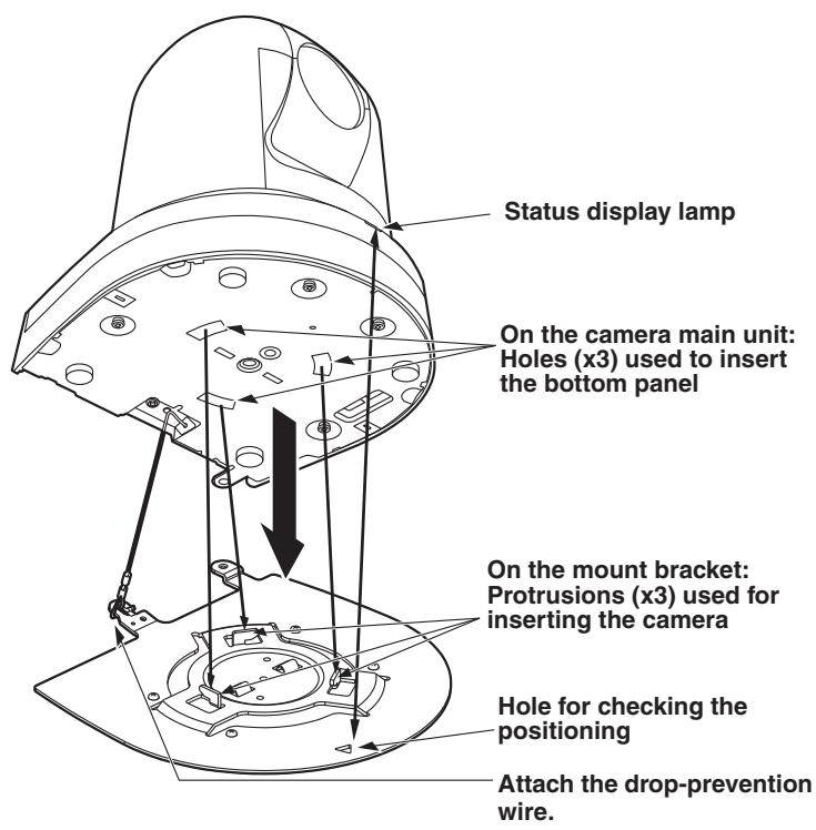
3 Attach the drop-prevention wire.
- Pull out the drop-prevention wire from the bottom panel of the unit, and engage the end with the wire ring through the hole of the mount bracket hook.
- Pull the drop-prevention wire, and check that it has been attached securely to the hook.
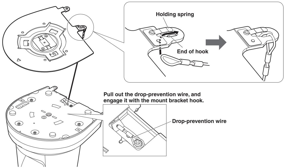
Notes
- Do not do this work while holding the camera head since doing so may result in malfunctioning of the unit.
- The drop-prevention wire is designed to be used for installation where the unit is suspended from an overhead surface so do not subject it to the weight of units other than the unit.
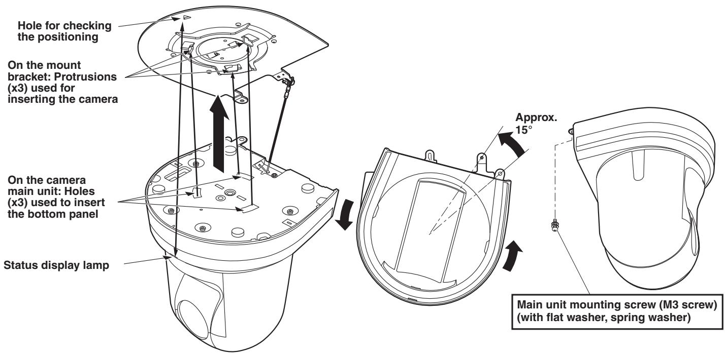
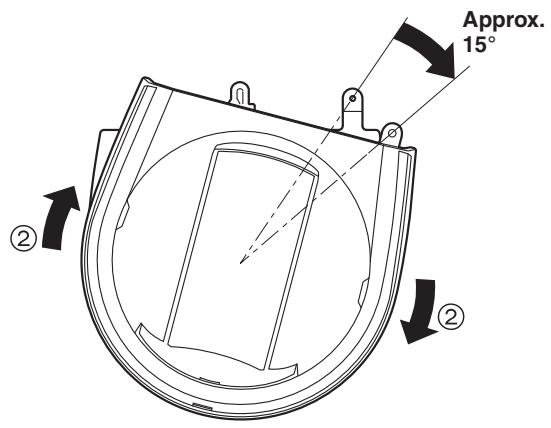
4 Mount the unit.
- Align the position of the hole for checking the positioning with the status display lamp.
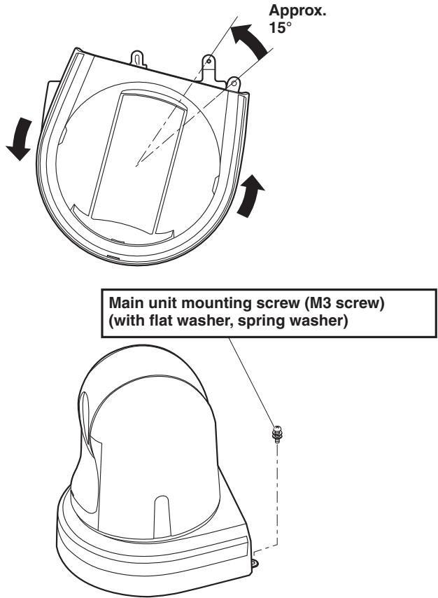
- Align the holes on the camera main unit used to insert the bottom panel with the protrusions on the mount bracket used for inserting the camera, push the camera to the bracket firmly, and rotate the main unit by about 15 degrees in the direction of the arrow.
- Secure the unit to the mount bracket using the main unit mounting screw (M3) as supplied.
- Attach the mount bracket securely with the prescribed tool using the clamping torque below. Be absolutely sure to verify that none of the screws are loose.
| Screw diameter | Clamping torque |
| M3 | 0.78 N·m {8 kgf·cm} |
Notes
- Do not do this work while holding the camera head since doing so may result in malfunctioning of the unit.
- Use only the screws supplied. Do not use any other screws.
- Check that the unit has been mounted securely with no tilting or wobbling.
- The unit must be secured without fail using the main unit mounting screw before any of the cables are connected.
5 Check the mounting.
Check out the following points.
- The main unit mounting screw must be mounted securely.
- The unit must not tilt, and it must be mounted exactly.
- The unit must be securely installed.
- The unit pedestal part must not rotate even when an attempt is made to turn it.
6 Connect the rear panel connectors.
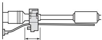
Anchor the AC adaptor cable in place using the cable clamp.
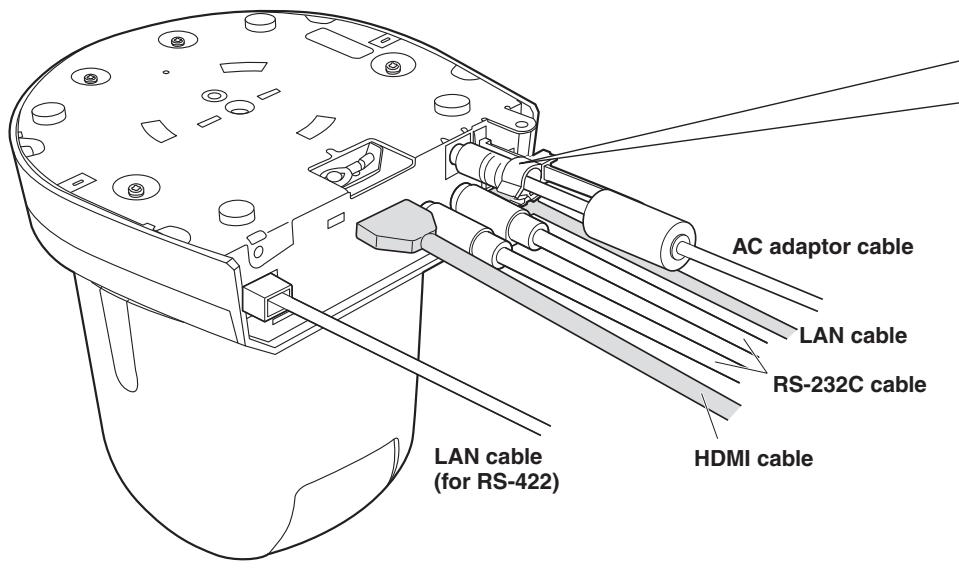
- How to secure the AC adaptor cable
① Loosely secure the cable clamp.
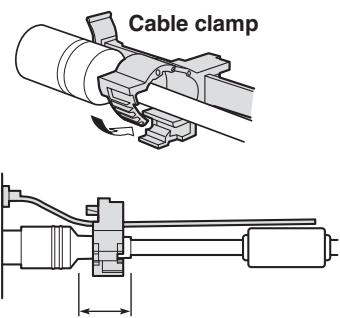
Loosely secure the cable clamp in the area shown above.
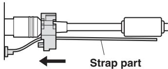
② Fasten the cable clamp.
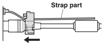
Take hold of the strap part, slide the cable clamp until it stops moving, and then secure it tightly.
Note
- Always disconnect the power supply before connecting or disconnecting cables. Connecting or disconnecting cables while the power is turned on may result in malfunctions.
The unit is in the standby condition when the AC adaptor is connected. The primary circuit is always "live" as long as the AC adaptor is connected to an electrical outlet.
■When using the WV-Q105A (optional accessory)
It is recommended that you provide an inspection opening or other such space for access purposes in the area near where the equipment is installed in order to facilitate installation and the wiring connections work.
Before mounting the mount bracket, check that the installation location is strong enough to withstand the total mass (approx. 2.0kg [4.41 lb]) which will be exerted once the camera is mounted.
When installing the unit on a ceiling, ensure that there is at least 100mm (3-15/16 inches) of space above the ceiling panel in the place where the unit will be used.
The unit can be installed on a ceiling panel with a thickness ranging from 5 mm (3/16 inches) to 40 mm (1-9/16 inches).
The drop-prevention wire (supplied with the WV-Q105A) must be used when mounting the direct ceiling mount bracket.
When installing the unit on a ceiling
1 Refer to the Operating Instructions of the WV-Q105A direct ceiling mount bracket, and attach the WV-Q105A as well as the drop-prevention wire angle and drop-prevention wire supplied with the WV-Q105A to the anchor bolts.
Mounting the anchor bolts and direct ceiling mount bracket ()
This job is facilitated if the direct ceiling mount bracket is loosely secured to the ceiling panel in one place, and the direct ceiling mount bracket and anchor bolts are vertically aligned before the nuts are tightened up.
2 First, remove the screws which were loosely fastened in step 1, and then align the camera mount bracket of the AW-HE38 with the screw holes in the WV-Q105A direct ceiling mount bracket and mount it in place.
- Use the mounting screws (the M4-L60 Phillips head screws with adhesive) supplied with the WV-Q105A as the mounting screws.
- Fasten the AC adaptor securely to the bottom or other surface of the reinforcing member made of channel steel where dust and other foreign matter will not accumulate.
- Do not place the AC adaptor directly onto the ceiling panel or other such surface.
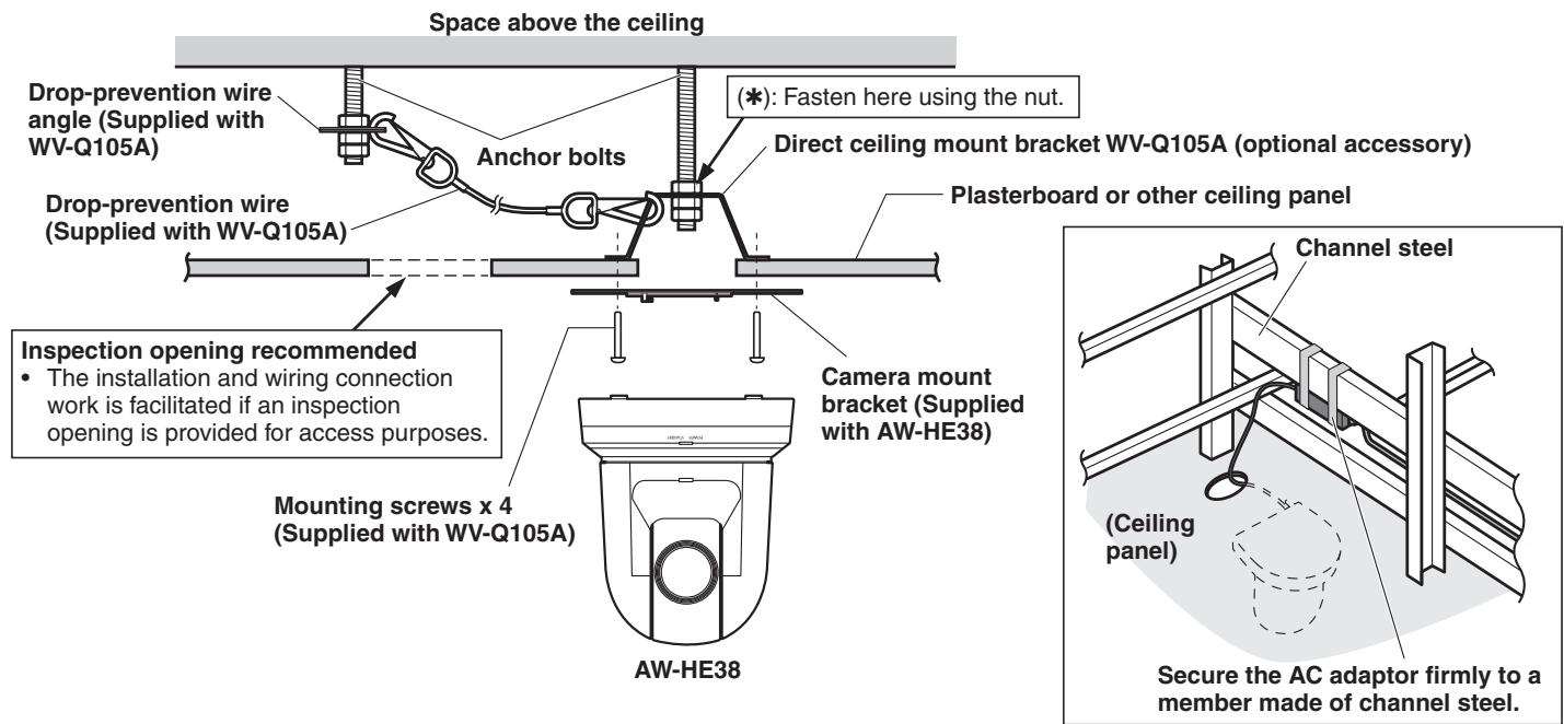
3 Install the AW-HE38 camera by following the procedure starting with step 3 on page 9.
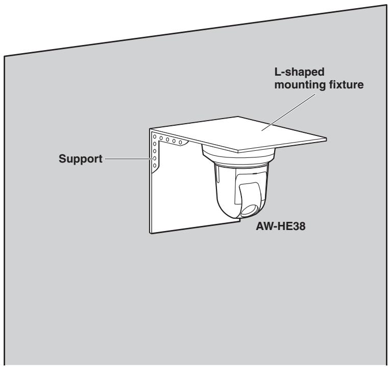
When installing the unit on a wall (installation example)
1 Before proceeding, fashion an L-shaped mounting fixture, and attach the fixture securely to the wall where the unit will be installed.
IMPORTANT
- Before installing the unit, check that the surface of the wall where the unit will be installed is strong enough to bear not only the total weight (approx. 2.0kg [4.41 lb]) of the camera once it has been installed but also the weight of the L-shaped mounting fixture and its supports.
- Use supports that are strong enough to withstand the total weight of the camera once it has been installed and any vibration or other forces to secure the L-shaped mounting fixture.
If the supports are not capable of bearing this weight and forces, the unit may become detached from the installation surface or it may fall off, possibly causing injury.
2 Refer to steps 1 to 3 in "When installing the unit on a ceiling" (page 12), and install the AW-HE38.
1 Turn off the circuit breaker and power.
2 Disconnect the cables.
Disconnect the power cable, video cable, and control cable, etc.
3 Remove the main unit mounting screw used to secure the unit and mount bracket.
4 Push the unit (①). Turn it approximately 15 degrees away from the installed position (②), and remove it (③).
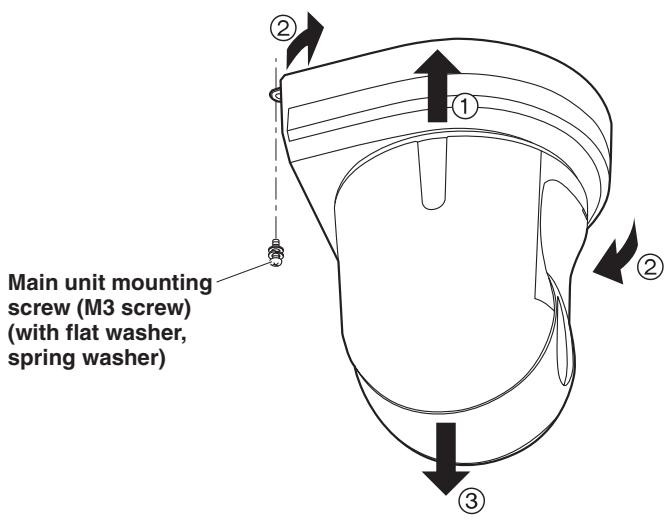
Note
- Do not do this work while holding the camera head since doing so may result in malfunctioning of the unit.
5 Disengage the drop-prevention wire from the mount bracket.
Stand-alone installation
(when the mount bracket is going to be used)
The same steps are followed as for the kind of installation where the unit is suspended from an overhead surface (pages 8 to 11).
1 Check the mounting space.
Note
- As with installing the unit suspended from an overhead surface, carefully check the space where the unit will be mounted, and then decide if it is appropriate to install the unit in that space.
2 Mount the mount bracket onto the installation surface.
3 Attach the drop-prevention wire.
4 Mount the unit.
- Align the position of the hole for checking the positioning with the status display lamp.
- Align the holes on the camera main unit used to insert the bottom panel with the protrusions on the mount bracket used for inserting the camera, push the camera to the bracket firmly, and rotate the main unit by about 15 degrees in the direction of the arrow.
- Secure the unit to the mount bracket using the main unit mounting screw (M3) as supplied.
5 Check the mounting.
6 Connect the rear panel connectors.
- How to secure the AC adaptor cable
① Loosely secure the cable clamp.

Loosely secure the cable clamp in the area shown above.
② Fasten the cable clamp.
Take hold of the strap part, slide the cable clamp until it stops moving, and then secure it tightly.

Note
- Always disconnect the power supply before connecting or disconnecting cables. Connecting or disconnecting cables while the power is turned on may result in malfunctions.
The unit is in the standby condition when the AC adaptor is connected. The primary circuit is always "live" as long as the AC adaptor is connected to an electrical outlet.
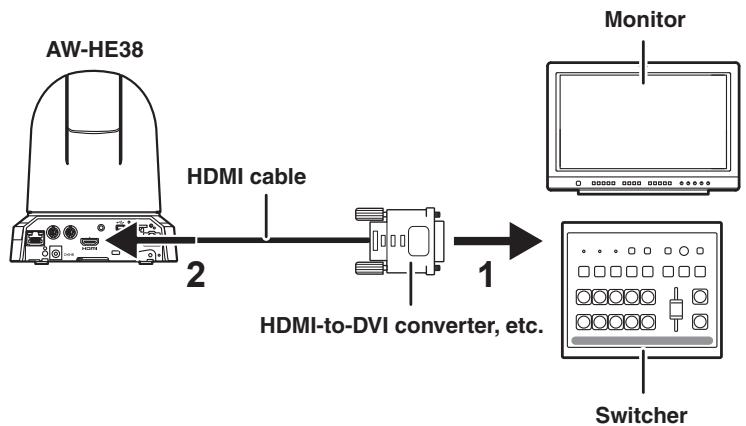
Note for connecting with an HDMI cable
When connecting with an HDMI cable using an HDMI-to-DVI converter, etc., be sure to connect the HDMI cable to the connector of the AW-HE38 last.
Connecting the HDMI cable to the connector of the AW-HE38 first may result in malfunction.
Stand-alone installation
(when the mount bracket is not going to be used)
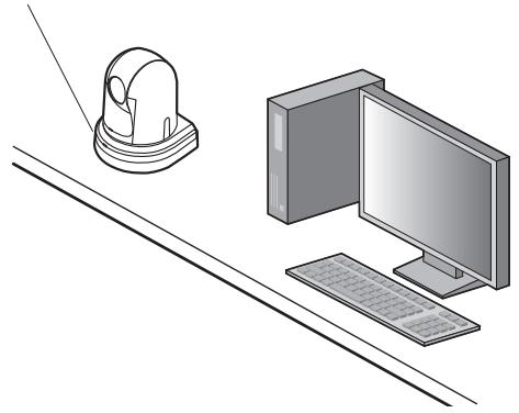
■When installing the unit on a desktop
Place the unit flat on the surface.
Notes
- Install the unit in a stable location which will not be susceptible to shaking. If the unit is installed in a location which is susceptible to shaking, this will cause the unit's images to shake in turn.
- Take care not to allow the unit to fall or otherwise be damaged during installation.
- When carrying the unit, do not hold it by its head.
- Do not take hold of the camera head or rotate it. Doing so may cause malfunctioning.
- Take care not to pull the connected cables. Doing so may cause the unit to fall and/or it may result in injury.
Ensure that the unit will not fall off.
Correct Incorrect
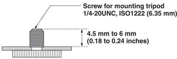
■When mounting the unit on a tripod
Attach the tripod to the threaded holes for mounting the camera on the camera's bottom panel.
Place the tripod on a completely flat and level surface.
Tighten the screws by hand to mount the tripod securely.
Use screw for mounting the tripod that satisfy the following standard.
Notes
- Do not install the unit where people will be passing back and forth.
- When using the unit mounted on a tripod, do not put the tripod high above the floor level.
- Mount the unit securely so there is no looseness. Looseness may cause the unit to fall off and/or result in injuries.
- When the unit is going to be used for a prolonged period of time, take steps to ensure that the unit will not topple or fall over and that it will not fall off or fall down. After using the unit, restore the installation location to its original state without delay.
Connecting an NDI|HX compatible switcher
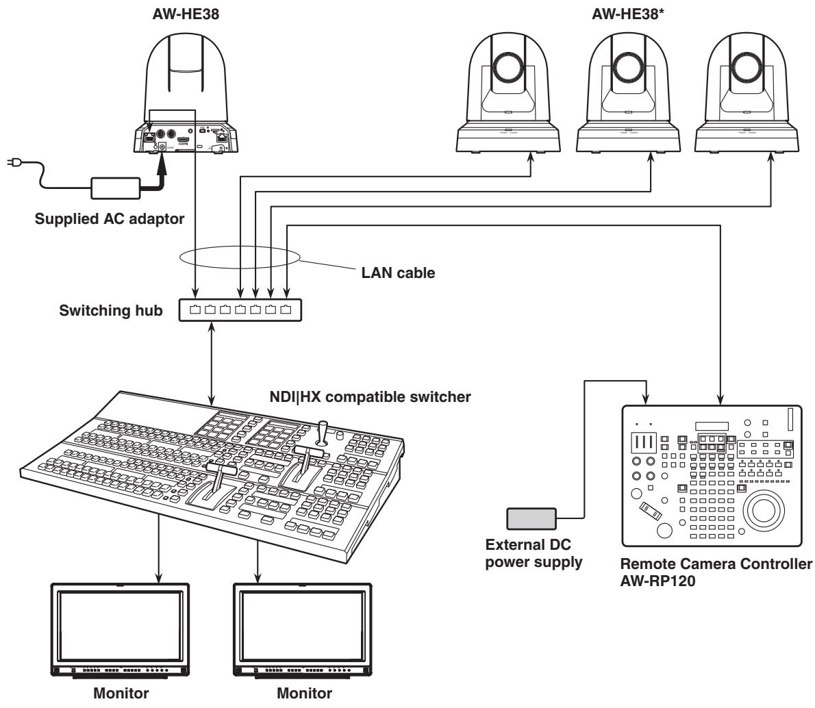
*: The AC adaptor provided with the unit is not shown in the above figure.
- Connecting a controller (AW-RP50/AW-RP120) (IP connection example)
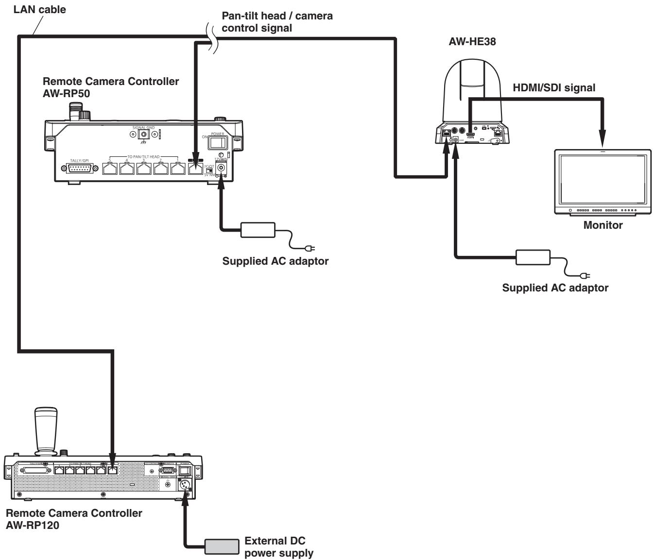
- The unit automatically detects the straight cable or crossover cable connected to the LAN connector.
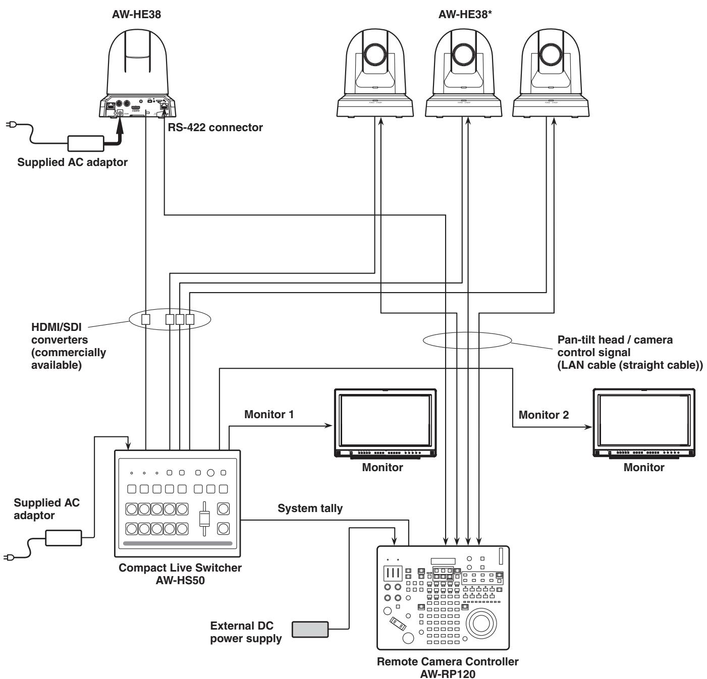
■System example 1 (connection with commercially available controller, RS-232C daisy-chain connection)

* You can connect up to seven cameras to a single controller.
- Configure the service switches at the bottom of the unit.
For details on the service switches, see "Service switch settings" (page 42).
| SW1 | Camera address setting (standard serial communication) | Set to AUTO or 1 to 7. (Set address numbers so that they do not duplicate each other.) |
| SW2 | ||
| SW3 | ||
| SW4 | Communication format | Enable standard serial communication (ON). |
| SW7 | Communication baud rate | Set to 9600 bps (OFF) or 38400 bps (ON) based on your commercially available controller. |
| SW8 | Communication connector | Set to RS-232C (ON). |
-
Configure the following items in the camera menu.
-
Display [System] menu [Protocol] [Model Select].
- Select [SEVIHD1], [SBRC300], or [SBRCZ330] for the protocol type.
■ System example 2 (connection with commercially available controller, RS-422 connection)
- Configure the service switches at the bottom of the unit.
For details on the service switches, see "Service switch settings" (page 42).
| SW1 | Camera address setting (standard serial communication) | Set to AUTO or 1 to 7. (Set address numbers so that they do not duplicate each other.) |
| SW2 | ||
| SW3 | ||
| SW4 | Communication format | Enable standard serial communication (ON). |
| SW7 | Communication baud rate | Set to 9600 bps (OFF) or 38400 bps (ON) based on your commercially available controller. |
| SW8 | Communication connector | Set to RS-422 (OFF). |
-
Configure the following items in the camera menu.
-
Display [System] menu [Protocol] [Model Select].
- Select [SEVIHD1], [SBRC300], or [SBRCZ330] for the protocol type.
Note
- Daisy-chain connections are not possible for RS-422 connections.
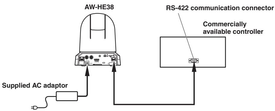
System example 3 (serial control)
*: The AC adaptor provided with the unit is not shown in the above figure.
- Make sure the LAN cable connected to the RS-422 connector is a straight cable.
System example 4 (IP control)
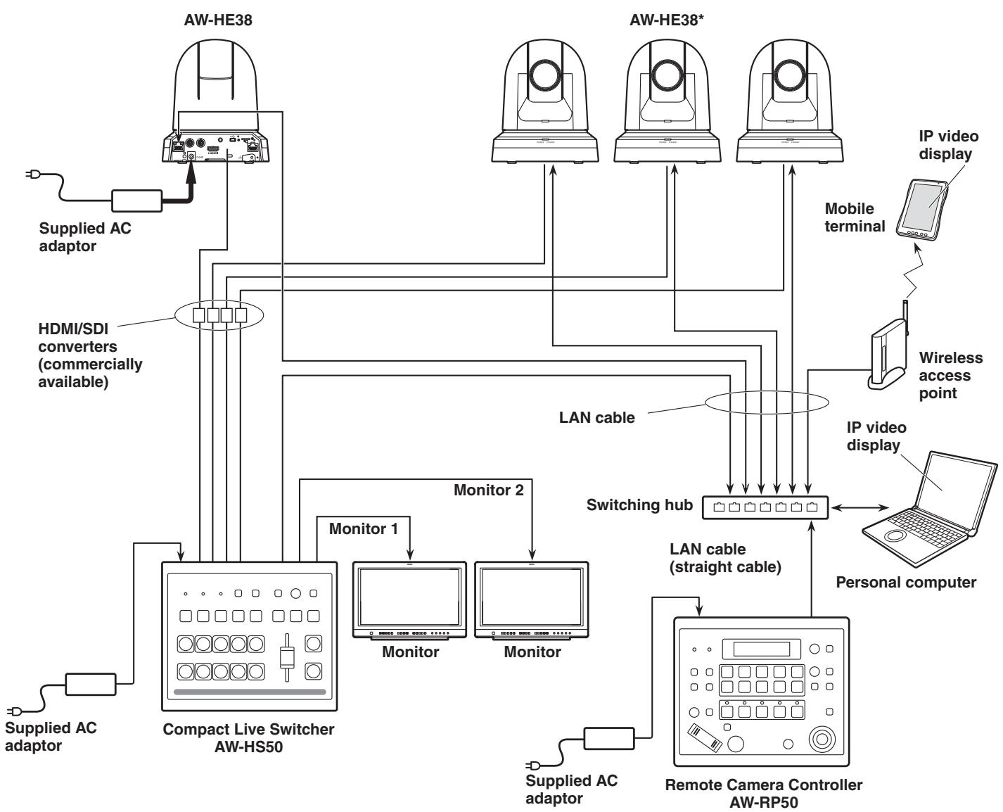
*: The AC adaptor provided with the unit is not shown in the above figure.
- The unit automatically detects the straight cable or crossover cable connected to the LAN connector.
System example 5 (infrared output connection)
You can point the infrared remote control of a commercially available controller toward the camera to operate it.
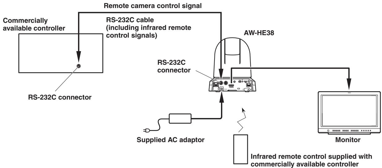
- Configure the service switches at the bottom of the unit.
For details on the service switches, see "Service switch settings" (page 42).
| SW6 | Infrared output | Set to ON. |
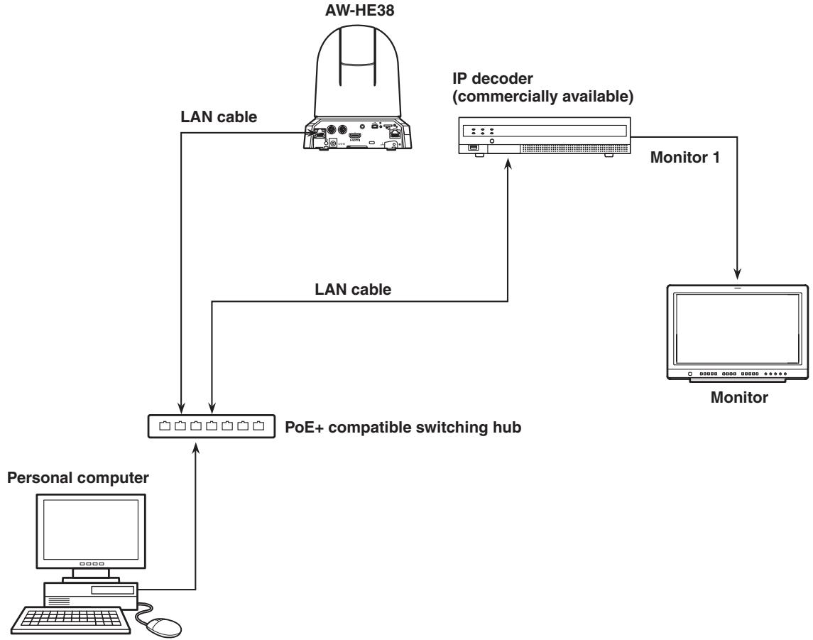
System example 6 (IP image transmission, PoE+)
■System example 7 (USB connection, Web camera)
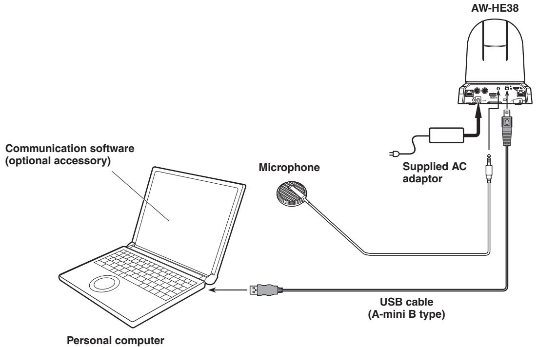
- Use a USB cable that is compatible with the USB 2.0 specification.
Connect a mini B connector to the unit. - The priority mode of the unit needs to be set to "USB".
For details, refer to "Priority mode tab [Priority Mode]" (page 65 in). - Use communication software (optional accessory) that is compatible with the USB Video Class and USB Audio Class.
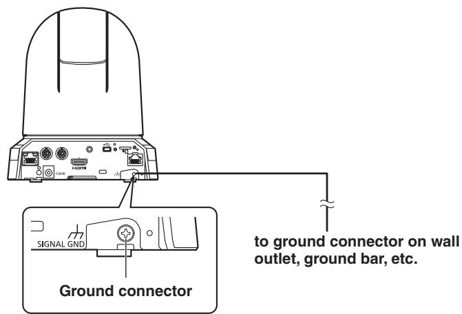
Note on grounding
- Ground the unit via the SIGNAL GND ground connector.
Unit: mm (inch)

The lightning flash with arrowhead symbol, within an equilateral triangle, is intended to alert the user to the presence of uninsulated "dangerous voltage" within the product's enclosure that may be of sufficient magnitude to constitute a risk of electric shock to persons.

The exclamation point within an equilateral triangle is intended to alert the user to the presence of important operating and maintenance (servicing) instructions in the literature accompanying the appliance.
WARNING:
- To reduce the risk of fire or electric shock, do not expose this equipment to rain or moisture.
- To reduce the risk of fire or electric shock, keep this equipment away from all liquids. Use and store only in locations which are not exposed to the risk of dripping or splashing liquids, and do not place any liquid containers on top of the equipment.
WARNING:
Always keep memory cards (optional accessory) or accessories (mounting screws) out of the reach of babies and small children.
CAUTION:
This apparatus can be operated at a voltage in the range of 100 - 240V AC.
Voltages other than 120V are not intended for U.S.A. and Canada.
Operation at a voltage other than 120 V AC may require the use of a different AC plug. Please contact either a local or foreign Panasonic authorized service center for assistance in selecting an alternate AC plug.
CAUTION:
The mains plug of the power supply cord shall remain readily operable.
The AC receptacle (mains socket outlet) shall be installed near the equipment and shall be easily accessible. To completely disconnect this equipment from the AC mains, disconnect the power cord plug from the AC receptacle.
CAUTION:
In order to maintain adequate ventilation, do not install or place this unit in a bookcase, built-in cabinet or any other confined space. To prevent risk of electric shock or fire hazard due to overheating, ensure that curtains and any other materials do not obstruct the ventilation.
CAUTION:
To reduce the risk of fire or electric shock and annoying interference, use the recommended accessories only.
CAUTION:
Check the installation at least once a year.
An improper installation could cause the unit to fall off resulting in personal injury.
CAUTION:
Do not pick up and move the unit while the tripod is attached.
The fitting may break under the weight of the tripod, which may result in injury.

indicates safety information.
FCC NOTICE (USA)
This device complies with part 15 of the FCC Rules.
Operation is subject to the following two conditions:
(1) This device may not cause harmful interference, and (2) this device must accept any interference received, including interference that may cause undesired operation.
FCC Note:
This equipment has been tested and found to comply with the limits for a class A digital device, pursuant to Part 15 of the FCC Rules. These limits are designed to provide reasonable protection against harmful interference when the equipment is operated in a commercial environment. This equipment generates, uses, and can radiate radio frequency energy, and if not installed and used in accordance with the instruction manual, may cause harmful interference to radio communications. Operation of this equipment in a residential area is likely to cause harmful interference in which case the user will be required to correct the interference at his own expense.
Warning:
To assure continued FCC emission limit compliance, the user must use only shielded interface cables when connecting to external units. Also, any unauthorized changes or modifications to this equipment could void the user's authority to operate it.

indicates safety information.
NOTIFICATION (Canada)
CAN ICES-3 (A)/NMB-3(A)
IMPORTANT SAFETY INSTRUCTIONS
1) Read these instructions.
2) Keep these instructions.
3) Heed all warnings.
4) Follow all instructions.
5) Do not use this apparatus near water.
6) Clean only with dry cloth.
7) Do not block any ventilation openings. Install in accordance with the manufacturer's instructions.
8) Do not install near any heat sources such as radiators, heat registers, stoves, or other apparatus (including amplifiers) that produce heat.
9) Do not defeat the safety purpose of the polarized or grounding-type plug. A polarized plug has two blades with one wider than the other. A grounding-type plug has two blades and a third grounding prong. The wide blade or the third prong are provided for your safety. If the provided plug does not fit into your outlet, consult an electrician for replacement of the obsolete outlet.
10) Protect the power cord form being walked on or pinched particularly at plugs, convenience receptacles, and the point where they exit from the apparatus.
11) Only use attachments/accessories specified by the manufacturer.
12) Use only with the cart, stand, tripod, bracket, or table specified by the manufacturer, or sold with the apparatus. When a cart is used, use caution when moving the cart/apparatus combination to avoid injury from tip-over.
13) Unplug this apparatus during lightning storms or when unused for long periods of time.
14) Refer all servicing to qualified service personnel. Servicing is required when the apparatus has been damaged in any way, such as power-supply cord or plug is damaged, liquid has been spilled or objects have fallen into the apparatus, the apparatus has been exposed to rain or moisture, does not operate normally, or has been dropped.

S3125A
WARNING:
- To reduce the risk of fire or electric shock, do not expose this equipment to rain or moisture.
- To reduce the risk of fire or electric shock, keep this equipment away from all liquids. Use and store only in locations which are not exposed to the risk of dripping or splashing liquids, and do not place any liquid containers on top of the equipment.
WARNING:
Always keep memory cards (optional accessory) or accessories (mounting screws) out of the reach of babies and small children.
CAUTION:
Do not remove panel covers by unscrewing. To reduce the risk of electric shock, do not rem the covers. No user serviceable parts inside. Refer servicing to qualified service personnel.
CAUTION:
The mains plug of the power supply cord shall remain readily operable.
The AC receptacle (mains socket outlet) shall be installed near the equipment and shall be easily accessible. To completely disconnect this equipment from the AC mains, disconnect the power cord plug from the AC receptacle.
CAUTION:
In order to maintain adequate ventilation, do not install or place this unit in a bookcase, built-in cabinet or any other confined space. To prevent risk of electric shock or fire hazard due to overheating, ensure that curtains and any other materials do not obstruct the ventilation.
CAUTION:
To reduce the risk of fire or electric shock and annoying interference, use the recommended accessories only.
CAUTION:
Check the installation at least once a year. An improper installation could cause the unit to fall off resulting in personal injury.
CAUTION:
Do not pick up and move the unit while the tripod is attached.
The fitting may break under the weight of the tripod, which may result in injury.

indicates safety information.
AEEYönetmeligiine Uygundur AEEC omplies with Directive of Turkey.
AC adaptor information
IS 616/IEC 60065

R-41016268
EMC NOTICE FOR THE PURCHASER/USER OF THE APPARATUS
1. Pre-requisite conditions to achieving compliance with the above standards
<1> Peripheral equipment to be connected to the apparatus and special connecting cables
- The purchaser/user is urged to use only equipment which has been recommended by us as peripheral equipment to be connected to the apparatus.
- The purchaser/user is urged to use only the connecting cables described below.
<2> For the connecting cables, use shielded cables which suit the intended purpose of the apparatus.
Video signal connecting cables
Use double shielded coaxial cables, which are designed for 75-ohm type high-frequency applications, for SDI (Serial Digital Interface).
Coaxial cables, which are designed for 75-ohm type high-frequency applications, are recommended for analog video signals.
Audio signal connecting cables
If your apparatus supports AES/EBU serial digital audio signals, use cables designed for AES/EBU.
Use shielded cables, which provide quality performance for high-frequency transmission applications, for analog audio signals.
- Other connecting cables
Use double shielded cables, which provide quality performance for high-frequency applications, as connecting cables for IEEE1394 and USB.
- When connecting to the HDMI signal terminal, use multilayer shielded cables, which provide quality performance for high-frequency applications.
- If your apparatus is supplied with ferrite core(s), they must be attached on cable(s) following instructions in this manual.
2. Performance level
The performance level of the apparatus is equivalent to or better than the performance level required by these standards. However, the apparatus may be adversely affected by interference if it is being used in an EMC environment, such as an area where strong electromagnetic fields are generated (by the presence of signal transmission towers, cellular phones, etc.). In order to minimize the adverse effects of the interference on the apparatus in cases like this, it is recommended that the following steps be taken with the apparatus being affected and with its operating environment:
- Place the apparatus at a distance from the source of the interference.
- Change the direction of the apparatus.
- Change the connection method used for the apparatus.
- Connect the apparatus to another power outlet where the power is not shared by any other appliances.
InΦopMaζίДЯ nokynζε
| Виropobнik: | Panasonic Corporation | Панасонік Корпоршн |
| Адра са Виropobнika: | Kadoma, Osaka, Japan | Кадoma, Oсака, Рнонia |
| Краïna похожени: | China | Китуй |
For the AC mains plug of three pins
Caution for AC mains lead
For your safety, please read the following text carefully.
This appliance is supplied with a moulded three pin mains plug for your safety and convenience.
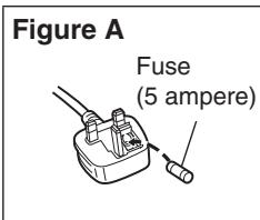
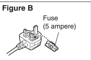
A 5-ampere fuse is fitted in this plug.
Should the fuse need to be replaced please ensure that the replacement fuse has a rating of 5-ampere and that it is approved by ASTA or BSI to BS1362.
Check for the ASTA mark or the BSI mark on the body of the fuse.
If the plug contains a removable fuse cover you must ensure that it is refitted when the fuse is replaced.
If you lose the fuse cover the plug must not be used until a replacement cover is obtained.
A replacement fuse cover can be purchased from your local dealer.
Before use
Remove the connector cover.
How to replace the fuse
The location of the fuse differ according to the type of AC mains plug (figures A and B).
Confirm the AC mains plug fitted and follow the instructions below.
Illustrations may differ from actual AC mains plug.
- Open the fuse cover with a screwdriver.
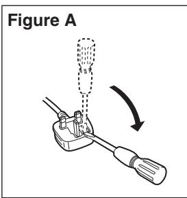
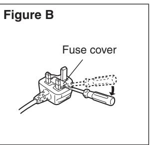
- Replace the fuse and close or attach the fuse cover.
indicates safety information.
Manufactured by: Panasonic Corporation, Osaka, Japan
Importer's name and address of pursuant to EU rules:
Panasonic Marketing Europe GmbH
Panasonic Testing Centre
Winsberging 15, 22525 Hamburg, Germany
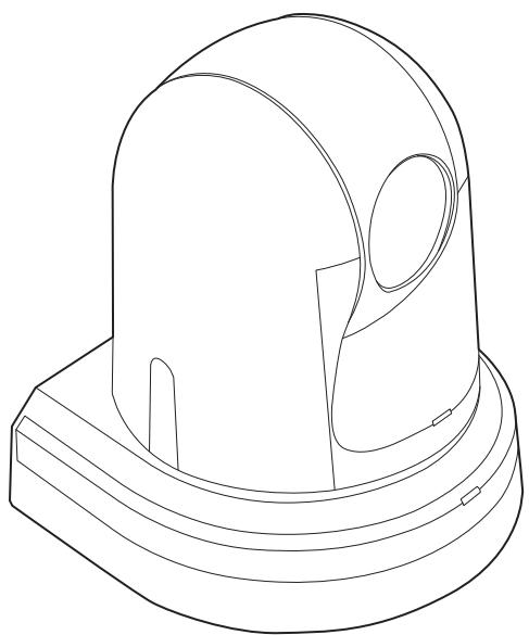
Overview
- The unit is a compact full HD camera integrated with a pan-tilt head and featuring a 1/2.3-type MOS sensor and digital signal processor (DSP).
- In addition to its optical 22x zoom lens, the unit comes with a 16x digital zoom allowing you to capture high-quality images that overflow with ambience. Using i.Zoom allows up to 30x zoom while maintaining HD quality.
- This product is compatible with NDI|HX technology of NewTek, Inc.
- The unit supports transmission of video to NewTek NDI compatible software applications and hardware devices over a network.
- When a controller is connected, camera operations can be performed smoothly via IP control or serial control.
- The unit features a Night mode, making it possible to shoot even under very-low-brightness conditions by exposing subjects to infrared rays.
- When the unit is connected to a computer via an IP network, it can be operated via a web browser while viewing the camera images on the screen.
- Connection with a Panasonic camera controller is also possible via Panasonic's proprietary serial communication format.
- The unit supports standard serial communication formats, allowing connection to commercially available controllers.
- The unit is available in two color variations (white or black) to suit your intended application and environment.
- Equipped with a newly developed codec engine, the unit can output Full HD images at up to 60 fps via a network.
- Changing the Priority Mode enables operation for various applications.
■Required personal computer environment
| CPU | When using 1080/60p [59.94Hz] and 1080/50p [50Hz] Intel® Core™ i7 3.4 GHz or higher recommended Other than above Intel® Core™2 Duo 2.4 GHz or higher recommended |
| Memory | For Windows: 1 GB or higher (2 GB or higher for Microsoft® Windows® 8.1, Microsoft® Windows® 8, Microsoft® Windows® 7 64-bit edition) For Mac: 2 GB or more |
| Network function | 10BASE-T or 100BASE-TX port × 1 |
| Image display function | Resolution: 1024 × 768 pixels or more Color generation: True Color 24-bit or more |
| Supported operating system and Web browser | Windows Microsoft® Windows® 8.1 Pro 64-bit/32-bit *1 Windows® Internet Explorer® 11.0 Microsoft® Windows® 8 Pro 64-bit/32-bit *1 Windows® Internet Explorer® 10.0 *1 Microsoft® Windows® 7 Professional SP1 64-bit/32-bit *2 Windows® Internet Explorer® 8.0 / 9.0 / 10.0 / 11.0 *3 |
| Mac OS X v10.8 Safari 6.2 OS X v10.9 Safari 7.1 OS X v10.10 Safari 8.0 | |
| iPhone / iPad / iPod touch iOS 8.3 Standard browser | |
| Android Android OS 4.4 Standard browser | |
| Other | Adobe® Reader® (for viewing the operating instructions available on the website) |
1: Use the desktop version of Internet Explorer. (Internet Explorer for Windows UI is not supported.)
2: Windows® XP compatibility mode is not supported.
*3: The 64-bit version of Internet Explorer® is not supported.
IMPORTANT
- Failure to provide the required personal computer environment may slow down the delineation of the images on the screen, make it impossible for the web browser to work and cause other kinds of problems.
Memo
- Use the desktop version of Internet Explorer. (Internet Explorer for Windows UI is not supported.)
- For the most recent information on compatible operating systems and web browsers, visit the support desk at the following web site.
http://pro-av.panasonic.net/
Disclaimer of warranty
IN NO EVENT SHALL Panasonic Corporation BE LIABLE TO ANY PARTY OR ANY PERSON, EXCEPT FOR REPLACEMENT OR REASONABLE MAINTENANCE OF THE PRODUCT, FOR THE CASES, INCLUDING BUT NOT LIMITED TO BELOW:
⑦ LOSS OF REGISTERED DATA CAUSED BY ANY FAILURE.
⑧ Indemnity about recorded content
① ANY DAMAGE AND LOSS, INCLUDING WITHOUT LIMITATION, DIRECT OR INDIRECT, SPECIAL, CONSEQUENTIAL OR EXEMPLARY, ARISING OUT OF OR RELATING TO THE PRODUCT;
② PERSONAL INJURY OR ANY DAMAGE CAUSED BY INAPPROPRIATE USE OR NEGLIGENT OPERATION OF THE USER;
(3) UNAUTHORIZED DISASSEMBLE, REPAIR OR MODIFICATION OF THE PRODUCT BY THE USER;
(4) INCONVENIENCE OR ANY LOSS ARISING WHEN IMAGES ARE NOT DISPLAYED, DUE TO ANY REASON OR CAUSE INCLUDING ANY FAILURE OR PROBLEM OF THE PRODUCT;
⑤ ANY PROBLEM, CONSEQUENTIAL INCONVENIENCE, OR LOSS OR DAMAGE, ARISING OUT OF THE SYSTEM COMBINED BY THE DEVICES OF THIRD PARTY;
⑥ ANY DEMANDS FOR COMPENSATION, CLAIMS, ETC. OCCASIONED BY THE INFRINGEMENT OF PRIVACY BY INDIVIDUALS OR ORGANIZATIONS WHOSE IMAGES WERE SHOT BY THE USER BECAUSE THESE IMAGES (INCLUDING THE RECORDINGS MADE) WERE MADE AVAILABLE BY THE USER BECAUSE IN THE PUBLIC DOMAIN FOR SOME REASON OR OTHER OR BECAUSE THE IMAGES ENDED UP BEING USED FOR PURPOSES OTHER THAN THE ONE DESCRIBED ABOVE;
Panasonic does not accept any responsibility for damages directly or indirectly due to any type of problems that result in loss of recording or edited content, and does not guarantee any content if recording or editing does not work properly. Likewise, the above also applies in a case where any type of repair is made to this unit.
Network security
As you will use the unit connected to a network, your attention is called to the following security risks.
① Leakage or theft of information through the unit
(2) Use of the unit for illegal operations by persons with malicious intent
(3) Interference with or stoppage of the unit by persons with malicious intent
It is your responsibility to take precautions such as those described below to protect yourself against the above network security risks.
- Use the unit in a network secured by a firewall, etc.
- If the unit is connected to a network that includes personal computers, make sure that the system is not infected by computer viruses or other malicious entities (using a regularly updated antivirus program, anti-spyware program, etc.).
- Protect your network against unauthorized access by restricting users to those who log in with an authorized user name and password.
- After accessing the unit as an administrator, be sure to close all web browsers.
- Change the administrator password periodically.
- Restrict access to the unit by authenticating the users, for example, to prevent setting information stored on the unit from leaking over the network.
- Do not install the camera in locations where the camera or the cables can be destroyed or damaged by persons with malicious intent.
- Avoid connections that use public lines.
Memo
Concerning user authorization
User authentication on the unit can be performed via digest authentication or basic authentication. If basic authentication is used without using a dedicated line equipped with an authentication function, password leaks may occur.
Usage restrictions
Use of the same segment is recommended for the network in which the unit and the controller or personal computer are connected.
If the equipment uses connections with different segments, events based on the settings inherent to the network equipment, for instance, may occur so check this thoroughly prior to operation.
Multiple number of formats supported
- You can switch between the following formats via the camera menus or a web browser.
Supported formats:
1080/59.94p (HDMI only), 1080/59.94i, 1080/29.97p, 1080/29.97PsF, 720/59.94p, 1080/50p (HDMI only), 1080/50i, 1080/25p, 1080/25PsF, 720/50p
1/2.3-type MOS sensor and high-performance 22x zoom lens featured
- A newly developed 1/2.3-type MOS sensor and DSP (digital signal processor) are incorporated.
High-quality pictures are obtained by video processing in many different kinds of ways. - In addition to its optical 22x zoom lens, the unit comes with a 16x digital zoom to achieve high-quality images that overflow with ambiance.
Using i.Zoom allows up to 30x zoom while maintaining HD quality. - The unit is equipped with functions that allow clean and clear reproduction of images in a wide range of applications, such as high dynamic range (HDR) and dynamic range stretch (DRS) functions that compensate for overexposure and loss of dark detail and a digital noise reduction (DNR) function that allows you to shoot scenes clearly by minimizing image lag even in dark locations.
Easy operation of unit enabled by its integration with a high-performance pan-tilt head unit
- High-speed operations with maximum speed of 300^ / s during preset, and 90^ / s during manual
- Wide rotational angles with a panning range of ± 175^ and a tilting range from -30^ to +90^
- Quiet operation with noise levels of NC35 (normal speed) and NC40 (during preset)
- Storage of up to 100 positions in the preset memory (The number of preset memories that can be used varies from one controller to another.)
Night mode incorporated
- Infrared shooting is supported.
The kind of shooting which is normally difficult under very-low-brightness conditions is now possible by exposing the subjects to infrared rays.
(Black-and-white images are output in this case.) - The iris will be fixed at open.
IP video output function featured
- The unit is equipped with image compression and IP transmission LSI capabilities. IP video transmission in SD format is possible.
- The unit is equipped with image compression and IP transmission LSI capabilities. Output in Full HD quality at up to 60 fps.
- Employing the functions of this chip together with IP control opens the door to uses in a wide range of applications including the control of the camera from a remote location.
High degree of compatibility with Panasonic's currently available controllers, enabling a flexible system to be put together
- A maximum of five units can be operated by serial control from one of Panasonic's currently available controllers (AW-RP50, AW-RP120 and AK-HRP200).
The unit can also be used together with the cameras and pan-tilt head unit systems currently available from Panasonic Corporation so that an existing system can be used to advantage to put together a system that is even more flexible.
Notes
- It may be necessary to upgrade the version of the controller in order to support the unit.
- The maximum distances between the units and controller is 1000 meters (3280 ft). (when serial control is exercised)
Use of an external device or some other means must be provided separately in order to extend the video signal connections.
Standard serial communication support
- Connect up to seven cameras to a commercially available controller via RS-232C interface.
Integrated pan-tilt head unit, camera and lens to facilitate installation
- By designing the camera, lens and pan-tilt head as a single integrated unit, the time taken for the installation work has been drastically reduced.
Use of easy-to-operate wireless remote control (optional accessory) is possible
- A wireless remote control capable of operating up to four units can be used.
It can easily be used to set the various functions or switch between them while viewing the menu screens.
Flexible camera layout enabled by simple connection and installation
- The unit features excellent connectivity and installability thanks to the IP control; a lightweight main unit, and the turn-lock mechanism, which enables the user to install it on his or her own (only when used indoors).
Note
- Bear in mind that the unit is designed to be used indoors only: It cannot be used outdoors.
Easy connections and settings courtesy of IP control
- Up to a hundred units can be operated by IP connection from a Panasonic controller (AW-RP50, AW-RP120 and AK-HRP200). (The maximum length of the LAN cables is 100 meters [328 ft].)
- By automatically recognizing the IP addresses and changing their allocation, the previous restrictions on the connections between the cameras and controllers using serial interfaces and the time and trouble taken to establish the various settings can be significantly reduced, and by configuring a network, flexible camera control can be implemented anywhere with any of the cameras.
PoE+ \*1 eliminates need for camera power configurations
- Configurations for camera's power supply are not necessary when the unit is connected to a network device that supports the PoE+ standard (IEEE802.3at compliant) ^*2 .
Notes
- If the AC adaptor and a PoE+ power supply are connected simultaneously, the AC adaptor will have priority.
- Use a category 5e cable or higher when using a PoE+ power supply. The maximum length of the cable between the power supply unit and the unit is 100 meters (328 ft). Using a cable that is lower than category 5e may result in reduced power supply capabilities.
1: Power over Ethernet Plus.
Referred to as "PoE+ in this manual.
2: For details on PoE+ power supply devices for which operation has been verified, consult your local dealer.
Equipped with a high dynamic range (HDR) imaging function
- This reduces overexposure and loss of dark detail in images with high light-dark contrast between the background and the subject.
Equipped with an image stabilization function
- When shaking is detected in the input image, the shaking is reduced by shifting the position of the area to be cropped according to the amount of shaking.
AW-RP50: Ver 3.10.00 or later
AW-RP120: Ver 2.10.00 or later
AK-HRP200:Ver 4.10-00-0.00 or later
- If the version older, an upgrade is required.
For details on upgrading, visit the support page on the following website.
http://pro-av.panasonic.net/
- For details on AW-RP555 and AW-RP655, refer to page 23 in the
.
Accessories
Check that the following accessories are present and accounted for.
- After removing the product from its container, dispose of the power cable cap and packing materials in an appropriate manner.
| ■ Mount bracket for installation surface (Hanging / Desktop)............1 (→ page 9, page 15) | ■ Main unit mounting screw (with flat washer, spring washer) M3 x 6 mm..........1 (→ page 10, page 15) | ■ Drop-prevention wire..........1 (already attached to the unit) (→ page 9, page 15) | ■ Bracket mounting screws /bind-head) M4 x 10 mm..........4 (→ page 9, page 15) |
| ■ AC adaptor..........1 | ■ Power cable (1.5 m [4.92 ft]) for AW-HE38HWPC, AW-HE38HKPC..........1 | for AW-HE38HWE, AW-HE38HKE | ......3 |
| · For U.K. and Saudi Arabia | · For India only | ||
| · For Continental Europe, etc. | · This product is equipped with 3 types of AC mains cable. Appropriate mains cable must be used in each local area, since the other type of mains cable is not suitable. |
Optional accessories
- Wireless remote controller AW-RM50G
(Size "AA", "R6" or "LR6" dry battery x 2, obtained separately)
- Direct ceiling mount bracket WV-Q105A
Shoot under the proper lighting conditions.
To produce pictures with eye-pleasing colors, shoot under the proper lighting conditions.
The pictures may not appear with their proper colors when shooting under fluorescent lights.
Select the proper lighting as required.
To ensure a stable performance in the long term
Using the unit for prolonged periods in locations where the temperature and humidity levels are high will cause its parts to deteriorate, resulting in a reduction of its service life.
(Recommended temperature: Max. 35^ [95°F])
Ensure that a cooling unit or heating unit will not blow any air directly toward the installation location.
Image persistence on the MOS sensor color filters
If parts of the MOS sensor are exposed continuously to spotlights or other bright lights, the color filters inside the MOS sensor will deteriorate, and the parts concerned may become discolored. The discoloration may be noticeable when the direction of fixed monitoring is changed.
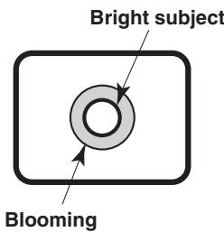
Do not point the camera at strong lights.
When parts of the MOS sensor are exposed to spotlights or other strong lights, blooming (a phenomenon where the edges of strong lights become blurred) may occur.
Concerning the color reproduction of MOS sensors
Depending on the color tones of the subjects, the color reproduction may deteriorate: This is normal and not indicative of any trouble.
What happens with high-brightness subjects
Flare may occur if an extremely bright light source is pointed at the lens. In a case like this, change the angle or take some other remedial action.
When using the automatic functions
- If "Full Auto" has been selected as the setting for Scene on the camera menu, for example, all the auto settings will be turned on, and manual operations will no longer be possible for some of the items.
- When using the ATW (auto tracking white adjustment) function under fluorescent lights, the white balance may vary.
- In some situations, it may be hard to focus at the auto setting. In cases like this, select the manual setting, and focus manually.
- The appropriate brightness may not be obtained when shooting bright objects using the auto settings for the gain and iris.
In cases like this, set the shutter speed to manual, and adjust.
Zooming and focusing
When the focus is set manually, out-of-focusing may occur during zooming.
After zooming, if necessary, either adjust the focus or set the focus to auto.
When using the focus at the manual setting, proceed with zooming after setting the focus position at the Tele end where the focusing accuracy is higher.
(However, if the distance from the unit to the subject is less than 1.0 meter [3.28 ft], the subject may shift out of focus at the Wide end.)
If zooming is performed to the Tele end after having adjusted the focus at the Wide end, out-of-focusing may occur.
Concerning the zoom position when the power is turned on
When the unit is turned on, the zoom, focus, and iris return to their positions from before the unit entered standby mode.
(This happens for the focus and iris when they were set manually.)
The operation will be performed with the [Preset Scope] settings applied in such cases.
However, this position may not be restored if, for instance, the power cable was disconnected during operation.
Operating temperature range
Avoid using the unit in cold locations where the temperature drops below 0^ (32°F) or hot locations where the temperature rises above 40^ (104°F) since these temperatures downgrade the picture quality and adversely affect the internal parts.
Concerning the HDMI interface standard
The unit has been certified as HDMI-compatible, but on rare occasions images may not be displayed depending on the HDMI device which has been connected to the unit.
Color bars
Color bars are used to adjust the color phase, and the widths and positions of these bars may differ from other models.
Concerning IP video refresh speed and operations from the web screen
The IP video refresh speed may be reduced and operations from the web screen may be slower, depending on the network environment used, performance of the personal computer or the mobile terminal, subjects and access count.
H.264 patent pool licensing
This product is licensed based on the AVC Patent Portfolio License, and the license does not extend beyond uses by users, who engage in the acts described below, for their own personal and non-profit applications.
(i) Recording of image information in compliance with the AVC standard (hereafter, "AVC videos")
(ii) Playing of AVC videos recorded by consumers engaging in personal activities or AVC videos acquired from licensed providers
For details, visit MPEG LA, LLC website (http://www.mpegla.com).
Concerning PoE+ power supply
The unit complies with the IEEE802.3at standard.
Use a PoE + compatible Ethernet hub and injector when using a PoE + power supply.
For details on recommended Ethernet hubs and injectors, consult your local dealer.
Turn off the power before connecting or disconnecting the cables.
Always disconnect the power supply before connecting or disconnecting cables.
Handle the unit carefully.
- Do not drop the unit or subject it to strong impact or vibration.
- Doing so may cause the unit to malfunction.
When the unit is not in use
Turn off the unit's power when it is not in use.
When the unit is no longer going to be used, do not leave it lying around, but be absolutely sure to remove it properly.
Do not touch the optical system parts.
The optical system parts are the very heart of the camera.
Under no circumstances must they be touched.
In the unlikely event that they have become dusty, remove the dust by using a camera blower or by wiping them gently with a lens cleaning paper.
Do not point the camera directly at the sun or a laser beam no matter whether it is turned on or not.
Taking images of the sun, laser beams, or other brightly lit subjects for prolonged periods of time may damage the MOS sensor.
Personal computer used
If the same image is displayed for a prolonged period on a PC monitor, the monitor may be damaged. Use of a screen saver is recommended.
Concerning the IP address setting
Do not run the Easy IP Setup Software on a multiple number of personal computers for a single camera and set the IP address at the same time.
Otherwise, you will be unable to complete the proper procedure and set the IP address correctly.
Do not allow foreign matter to make contact with the rotating parts.
Otherwise, trouble may be caused.
Keep the unit away from water.
Avoid all direct contact with water. Otherwise, problems may occur.
Maintenance
Disconnect the power supply before proceeding with maintenance.
Otherwise, you may injure yourself.
Wipe the surfaces using a soft dry cloth. Avoid all contact with benzine, paint thinners and other volatile substances, and avoid using these substances. Otherwise, the casing may become discolored.
Do not turn the camera head by hand.
Turning the camera head by hand may cause the unit to malfunction.
Use the unit in an environment with minimal moisture and dust.
Avoid using the unit in an environment with high concentration of moisture or dust since these conditions will damage the internal parts.
Disposal of the unit
When the unit has reached the end of its service life and is to be disposed of, ask a qualified contractor to dispose of the unit properly in order to protect the environment.
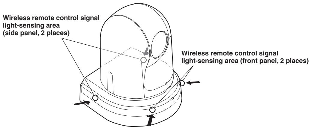
Concerning the wireless remote control (optional accessory)
The unit can be operated by remote control using a wireless remote control (model number: AW-RM50G) purchased separately. Check out the following points before using the wireless remote control.
- Point the wireless remote control at the unit's wireless remote control signal light-sensing area (front panel or side panel), and operate it within a range of 10 meters (32.8 ft) from these areas.
Refer to
- If the unit is installed near fluorescent lights, plasma monitors or other such products or if the unit is exposed to sunlight, the effects of the light may make it impossible for the unit to be operated using the wireless remote control.
Be sure to follow the steps below for installation and use.
- Take steps to ensure that the wireless remote control signal light-sensing area will not be exposed to the light from fluorescent lights, plasma monitors or other such products or from the sun.
-
Install the unit away from fluorescent lights, plasma monitors and other such products.
-
For about 10 minutes even after the batteries have been removed from the wireless remote control, the selection of the operation to be performed (the [CAM1], [CAM2], [CAM3] or [CAM4] button which was pressed last) will remain stored in the memory. When a longer period of time elapses, however, the selection is reset to the status established when the [CAM1] button was pressed.
Note
- The arrows in the figure below show the light-sensing directions in which the wireless remote control signals travel.
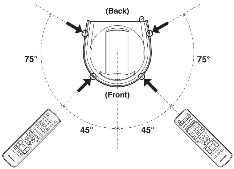
- Top view
Camera unit
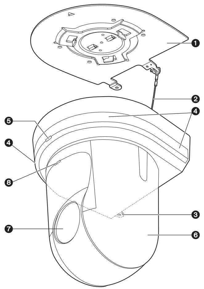
Mount bracket for installation surface (supplied accessory)
Mount this bracket onto the installation surface, and then attach the camera main unit to the bracket.
2Drop-prevention wire
Pull out the wire from the bottom panel of the camera main unit, and attach it to the hook of the mount bracket.
Hole for securing the camera pedestal
This hole is provided in the bottom panel of the camera pedestal.
Wireless remote control signal light-sensing area
Light sensors are located in four places; at the front of the camera pedestal and on either side.
Status display lamp
This lights in the following way depending on the status of the unit.
Orange: When the standby status is established
Green: When the power is on
Red: When trouble has occurred in the unit
Green and blinks twice:
When a signal matched by the remote control ID has been received from the wireless remote control (optional accessory) while the power is on
Orange and blinks twice:
When a signal which is not matched by the remote control ID has been received from the wireless remote control (optional accessory) while the power is on
Camera head
This rotates in the horizontal direction.
Lens unit
This rotates in the up and down direction.
Tally lamp
This comes on or goes off in response to the control from the controller but only when "On" has been selected as the tally lamp use setting.
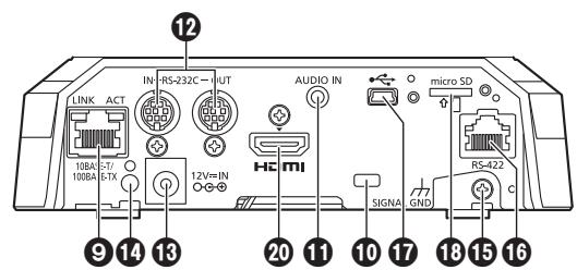
LAN connector for IP control [LINK/ACT]
This LAN connector (RJ-45) is connected when exercising IP control over the unit from an external device. Use a cable with the following specifications for the connection to the LAN connector:
When connecting through a hub:
LAN cable* (category 5 or above), max. 100 meters [328 ft]
When using a PoE+ compatible hub:
LAN cable* (category 5e or above), max. 100 meters [328 ft]
When a hub is not used:
LAN cable* (category 5 or above), max. 100 meters [328 ft]
*: Use of an STP (shielded twisted pair) cable is recommended.
10 Anti-theft wire mounting hole
Use this hole to attach the wire bracket (commercially available).
Audio input connector [AUDIO IN]
Inputs external audio (microphone, line).
RS-232C connectors [RS-232C IN/OUT]
Connect to RS-232C cables.
![PANASONIC AW-HN38H - RS-232C connectors [RS-232C IN/OUT] - 1](/content/2024/12/222167/images/fca09cb781de520dbc00610df6eb8589fb6ce30defdf723acc5ecffdfff6d70f.jpg)
RS-232C IN/OUT connector
- Mini DIN 8-pin (JST)
| RS-232C IN | RS-232C OUT | ||
| Pin No. | Signal | Pin No. | Signal |
| 1 | DTR_IN | 1 | DTR_OUT |
| 2 | DSR_IN | 2 | DSR_OUT |
| 3 | TXD_IN | 3 | TXD_OUT |
| 4 | GND | 4 | GND |
| 5 | RXD_IN | 5 | RXD_OUT |
| 6 | GND | 6 | GND |
| 7 | IR OUT R | 7 | NC |
| 8 | IR OUT L | 8 | NC |
Note
- Be aware that the polarities (+ / -) of the serial data may be different depending on the specifications of the device to be connected.
DC IN connector [12V = IN -C +]
Connect the AC adaptor supplied with the unit to this connector to supply the DC 12 V voltage to the unit.
Cable clamp
This is used to hold the cable connection to the DC IN connector and prevent it from becoming disconnected.
Ground connector
Connects to the ground connector on a wall outlet, ground bar, etc. for grounding. (page 25)
16 RS-422 connector [RS-422]
This RS-422 connector (RJ-45) is connected when exercising serial control over the unit from an external device.
Use a cable with the following specifications for the connection to this connector.
The tally lamp can be lit by shorting the TALLY signal (pin 2) with GND (pin 1).
Note
- Do not apply a voltage to the TALLY signal pin.
LAN cable* (category 5 or above, straight cable), max.
1000 meters [3280 ft]
*: Use of an STP (shielded twisted pair) cable is recommended.
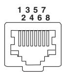
| Pin No. | Signal | Pin No. | Signal |
| 1 | GND | 5 | TXD + |
| 2 | TALLY | 6 | RXD + |
| 3 | RXD - | 7 | — |
| 4 | TXD - | 8 | — |
USB port
The unit can be used as a Web camera by connecting the unit and a personal computer with USB Video Class.
microSD card slot
The video and audio of the camera can be recorded to a microSD card in MP4 format.
Threaded hole (thread: 1/4-20UNC, ISO1222 [6.35 mm]) for mounting the camera
Use this hole when mounting the camera on a tripod, etc.
20 HDMI connector [HDMI]
This is the HDMI video signal output connector.
![PANASONIC AW-HN38H - HDMI connector [HDMI] - 1](/content/2024/12/222167/images/d172076eedcfdbd3c4fd55438eb503d960f162e10380f15ca3a5093f9f8df6e6.jpg)
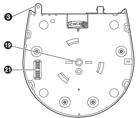
Service switches
| Function | OFF | ON | Factory setting | |
| SW1 | Camera address setting (standard serial communication) | See descriptions for SW1 to SW3 | OFF | |
| SW2 | OFF | |||
| SW3 | OFF | |||
| SW4 | Communication format | Panasonic proprietary serial communication | Standard serial communication | OFF |
| SW5 | Always leave at OFF (used for factory adjustments) | OFF | ||
| SW6 | Infrared output | Disable | Enable | OFF |
| SW7 | Communication baud rate | 9600 bps | 38400 bps | OFF |
| SW8 | Communication connector | RS-422 | RS-232C | OFF |
Notes
- Perform switch settings before turning the unit on.
- Cameras whose camera address setting switches are set to AUTO cannot coexist with cameras whose switches are set to 1 to 7.
- Manually setting multiple cameras to the same address will not allow you to control multiple cameras from a single controller simultaneously.
Service switch settings
(1) SW1 to SW3: Camera address setting switches Configure the camera address. Set this to AUTO under normal circumstances. When cameras are set to AUTO, addresses will be assigned to the cameras automatically in response operation from the controller in the order in which the cameras were connected. To manually configure the address, set the switches as follows.
(2) SW4: Communication format selection switch
Selects the communication format.
When this is set to ON, standard serial communication is enabled.
When this is set to OFF, Panasonic's proprietary serial communication is enabled.
(3) SW5: Maintenance switch
Fixed at OFF.
Do not change this switch setting.
(4) SW6: Infrared output switch When this is set to ON, infrared output is enabled. The signal received via the remote control sensor is output from pins 7 and 8 of the RS-232C IN connector. Signal output is disabled when this is set to OFF.
(5) SW7: Communication baud rate switch
When this is set to ON, the baud rate is 38400 bps.
When this is set to OFF, the baud rate is 9600 bps.
(6) SW8: Communication connector switch When this is set to ON, RS-232C is enabled. When this is set to OFF, RS-422 is enabled.
■ Wireless remote controller (optional accessory)
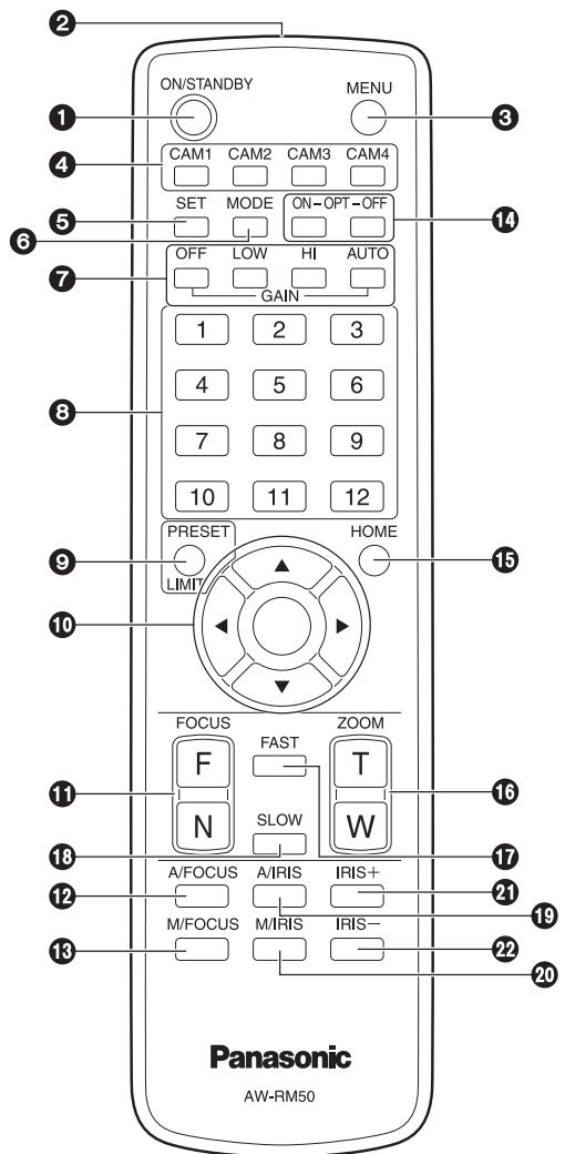
ON/STANDBY button
Each time this is pressed for 2 seconds, operation switches between turning on the unit's power and establishing the standby status.
Notes
- When operation is transferred to the standby mode: The current pan-tilt position is stored in the memory (as a POWER ON preset), and the panning/tilting moves so that the camera points in the backward-facing direction.
- When operation is transferred to the POWER ON mode: Panning/tilting moves to the position which was stored in the memory (as a POWER ON preset) when operation was transferred to the standby mode.
② Signal transmission window
3 MENU button
Each time this is pressed for 2 seconds, operation switches between displaying the unit's camera menu and exiting the camera menu.
When it is pressed quickly (for less than 2 seconds) while a menu is displayed, the setting change is canceled.
Furthermore, the pan and tilt movement range limits (limiters) are set and released by operating the MENU button, PRESET/LIMIT button and the pan-tilt buttons ([▲], [▼], [▲] and [▶]).
For details, refer to "Limiters" (pages 121 to 122 in the
CAM1 to CAM4 buttons
These are used to select the units that are to be operated. Once a button has been selected, the unit corresponding to the selected button can be operated.
SET button
If this button is pressed when one of the "Manual1 to 3" settings has been selected for "Scene" on the camera menu and the AWB A memory or AWB B memory has been selected by the white balance adjustment, the white balance is automatically adjusted and registered in the selected memory.
6MODE button
This is used to select the video signals which are output from the unit.
Each time it is pressed, the signals are switched between the color bar signals and camera video signals.
Note
- When the color bar is displayed, a test tone (1 kHz) is output according to the Audio setting in the camera menu. Be cautious of the volume on external devices.
GAIN buttons [OFF] [LOW] [HI] [AUTO]
These are used to set the gain.
The gain increase can be set in three steps using the [OFF], [LOW] and [HI] buttons.
[OFF] is set to 0 dB, [LOW] is set to 9 dB, and [HI] is set to 18 dB.
When the [AUTO] button is pressed, the AGC function is activated, and the gain is adjusted automatically depending on the light quantity.
The maximum gain of the AGC function can be set using the camera menu.
Preset memory call buttons [1] to [12]
These are used to call the information on the unit's directions and other settings, which have been registered in the unit's preset memories No.1 to No.12, and reproduce those settings.
Settings in preset memories No.13 and above cannot be called from the wireless remote control.
PRESET/LIMIT button
This is used to register the settings in the preset memories or set or release the limiters.
When a preset memory call button is pressed while the PRESET/LIMIT button is held down, the information on the unit's current direction and other settings is registered in the call button.
Preset memory call buttons [1] to [12] correspond to the unit's No.1 to No.12 preset memories.
Furthermore, the pan and tilt movement range limits (limiters) are set and released by operating the PRESET/ LIMIT button, MENU button and the pan/tilt buttons ([▲], [▼], [▲] and [▶]).
For details, refer to "Limiters" (pages 121 to 122 in the
Pan-tilt buttons and menu operation buttons [▲][▼][〈] [▶] [○]
(1) These are used to change the unit's direction.
The unit is tilted in the up/down direction using the [] and [] buttons and panned in the left/right direction using the [] and [] buttons.
The [ ] button does not work during tilting and panning.
When the [ ] or [ ] and [] or [] buttons are pressed at the same time, the unit moves diagonally.
(2) The buttons are used for menu operations when the unit displays the camera menus.
Use the [], [], [] and [] buttons to select the menu items.
When a selected item has a sub-menu, the sub-menu will be displayed by pressing the [O] button.
When the cursor is aligned with a particular item and the [0] button is pressed on the setting menu at the bottom hierarchical level, the setting of the selected item blinks.
When the [ ] button is pressed after the setting has been changed using the [ ],[ ],[ ] and [ ] buttons, the setting stops blinking, and the new setting is entered.
With a regular menu, the new setting is reflected immediately after it has been changed if the change was made from the setting in the blinking status, but there are some menus (Scene, Format and Initialize) where it is reflected only after the [0] button has been pressed, the blinking has stopped and the new setting has been entered.
If the MENU button is pressed quickly (for less than 2 seconds) while the setting is in the blinking status, the change will be canceled, and the setting selected prior to the change will be restored.
FOCUS buttons [F] [N]
These are used to adjust the lens focus manually when the manual setting is established for the lens focus. The focus is adjusted in the far using the [F] button and in the near using the [N] button.
A/FOCUS button
This is used when automatically adjusting the lens focus.
M/FOCUS button
This is used when manually adjusting the lens focus. The FOCUS buttons ([F] and [N]) are used when performing the actual adjustment.
OPT buttons [ON] [OFF]
This is used to select the Day mode or Night mode.
[ON]: Night mode
[OFF]: Day mode (standard setting)
15 HOME button
When this is pressed for 2 seconds, the unit's direction (panning or tilting) returns to the reference position.
16ZOOM buttons [T] [W]
These are used to adjust the lens zoom.
The zoom is adjusted in the wide-angle using the [W] button and in the telephoto using the [T] button.
FAST button
This is used to change the movement speed at which the panning, tilting, zooming and focusing operations are performed to the high speed.
When the button is tapped, the movement speed can be set to the normal high-speed operation. When the button is held down, it can be set to an even faster high-speed operation. Tap the button to return the movement speed to the normal high-speed operation.
Note
- The operating speed for panning and tilting when the preset memory settings have been called can be changed using the Preset Speed item and Preset Speed Table item of the camera menu.
SLOW button
This is used to change the movement speed at which the panning, tilting, zooming and focusing operations are performed to the low speed.
When the button is tapped, the movement speed can be set to the normal low-speed operation. When the button is held down, it can be set to an even slower low-speed operation. Tap the button to return the movement speed to the normal low-speed operation.
19A/IRIS button
This establishes the setting for adjusting the lens iris automatically in line with the light quantity.
20M/IRIS button
This establishes the setting for adjusting the lens iris manually.
The IRIS + and IRIS - buttons are used when performing the actual adjustment.
IRIS + button
This is used to adjust the lens iris in the opening direction.
2IRIS - button
This is used to adjust the lens iris in the closing direction.
The wireless remote control (optional accessory) is capable of operating up to four units.
IDs are used to set which units are selected when the [CAM1], [CAM2], [CAM3] and [CAM4] buttons on the wireless remote control have been pressed.
- When operating a multiple number of these units using wireless remote controls, set a different remote control ID for each control.
- When using one unit, set the remote control ID to "CAM1" unless the setting needs to be changed.
Setting procedure
Operate the unit's camera menu or the web screen to select a remote control ID ([CAM1] to [CAM4]).
The camera's [CAM1] to [CAM4] settings correspond to the [CAM1] to [CAM4] buttons on the wireless remote control.
(The factory setting is "CAM1".)
For details, see "IR ID" on page 48 or page 85 of the
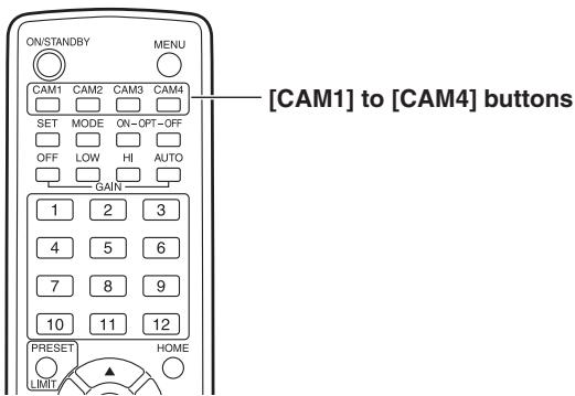
■Use the Easy IP Setup Software to establish the unit's settings
The settings related to the unit's network can be established using the Easy IP Setup Software supplied.
You can obtain Easy IP Setup Software (EasyIPSetup.exe) by downloading it from the following website.
http://pro-av.panasonic.net/
To establish the settings for a multiple number of units, the settings must be selected for each camera involved. If the settings cannot be established using the Easy IP Setup Software, select the settings separately for the unit and personal computer on the network page of the setting menu. For further details, refer to the "Operating Instructions -
Notes
- If, after the network settings have been established, another device in the same network has the same IP address, the network operations will not be performed properly.
Set the IP address in such a way that it does not duplicate an existing IP address.
- Do not establish network settings from a multiple number of Easy IP Setup Software programs at the same time for a single camera.
Similarly, do not perform the "Auto IP setting" operation of the remote camera controller (AW-RP50 or AW-RP120) at the same time.
The IP address settings may no longer be recognized as a result.
- When you start the Easy IP Setup Software, you may be asked for the administrator account password.
- To enhance security, the Easy IP Setup Software is designed so that when around 20 or more minutes have passed after the power was turned on, the network settings of the target camera can no longer be configured.
It does this to improve the security.
When "20min" is selected for the enable time among the "Easy IP Setup accommodate period". (page 92 in the
- The Easy IP Setup Software cannot be used from a different subnet via a router.
1 Start the Easy IP Setup Software.
2 Click the [Search] button.
![PANASONIC AW-HN38H - Click the [Search] button. - 1](/content/2024/12/222167/images/31faae8fcc02679f7a5beb23bbb1ecb8c0e5e83dcf2c3506bbdfd2238a185bdc.jpg)
3 Click the MAC address/IPv4 address of the camera to be set, and click the [Network Settings] button.
![PANASONIC AW-HN38H - Click the MAC address/IPv4 address of the camera to be set, and click the [Network Settings] button. - 1](/content/2024/12/222167/images/4a138b7d04bfd62c7392b6c5c60cac0639c40716c2aa7a036b1ebb321cd00333.jpg)
Notes
- When a DHCP server is being used, the IP address allocated to the unit can be checked by clicking the [Search] button of the Easy IP Setup Software.
- If the same IP address is used for any additional cameras, the numbers of the additional cameras will be displayed in the "IPv4 overlap" column of the cameras concerned.
- When the [Access Camera] button is clicked, the Live screen of the selected camera is displayed.
4 Input the network items, and click the [Save] button.
![PANASONIC AW-HN38H - Input the network items, and click the [Save] button. - 1](/content/2024/12/222167/images/8768a5778d5722feca14c6d3c050a6040daecc38f8febb252022a5c81355b220.jpg)
Notes
- When a DHCP server is being used, "DNS" of the Easy IP Setup Software can be set to "Auto".
- After the [Save] button is clicked, it takes about 1 minute for the settings in the unit to be completed. If the AC adaptor or LAN cable is disconnected before the settings are completed, the settings will be canceled. In this case, repeat the steps to establish the settings.
- When a firewall (including software) has been introduced, enable access to all the UDP ports.
- When the Easy IP Setup Software is used for the first time, the [Program Compatibility Assistant] screen may appear after quitting the Easy IP Setup Software.
Select [This program installed correctly] in the [Program Compatibility Assistant] screen.
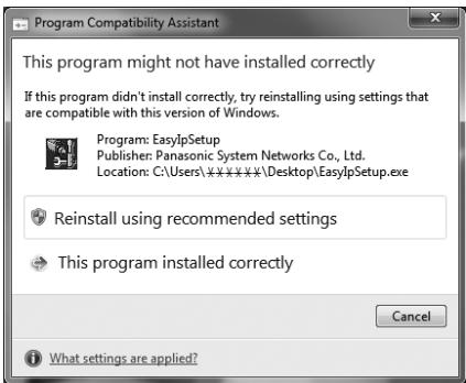
■ Installing the plug-in viewer software
To view IP images from the unit on a web browser, the "Network Camera View 4S" plug-in viewer software (ActiveX®) must be installed in your personal computer.
- When you display the Live screen [Live] on the personal computer for the first time, the installation screen for the plug-in viewer software (ActiveX) appears. Follow the instructions on the screen to perform installation.
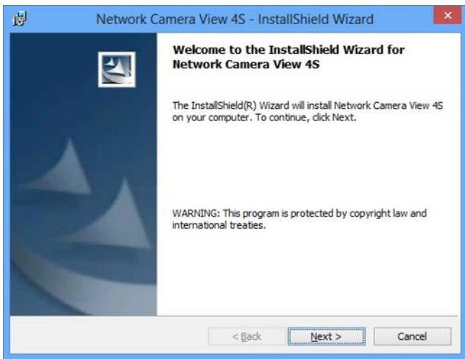
Notes
- [Automatic installation of viewer software] is set to [On] at the time of purchase, allowing you to install directly from the unit. If a message appears in the web browser's information bar, see page 135 in the
. - If the plug-in viewer software (ActiveX) installation screen continues to appear when switching screens, even after it is installed, restart the personal computer.
- To uninstall the plug-in viewer software, select [Control Panel] - [Programs] - [Uninstall a program] in Windows, and remove "Network Camera View 4S".
- If installation of the plug-in viewer software fails, close Internet Explorer with × while the above screen is displayed and then click [Next].
■User authentication
The unit can be configured to allow access from the internet. To prevent infringement of privacy and personality rights, information leaks, and other issues concerning unauthorized access by third parties, we recommend enabling the user authentication function upon installation. We also recommend using DIGEST authentication when connecting to a device that supports DIGEST authentication.
- The AW-RP50, AW-RP120, and AK-HRP200 support DIGEST authentication.
Preparation:
- Startup the web browser and display the "Live" page on a PC.
- Click "Setup" button and then click "User mng." button.
The user authentication window will be displayed.
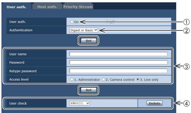
① Select "On" for "User auth."
- Set to "Off" by default.
Then click "Set" button.
(2) (When using a device that supports DIGEST authentication)
Select "Digest" for "Authentication".
Then click "Set" button.
③ Register a new user name and password
- Select "1. Administrator" for the access level.
Then click "Set" button.
④ Delete the default user name.
Click the "Delete" button after selecting the user name to be deleted ("admin[1]").
* Depending on the model used, the screens shown in the explanations may differ to the actual camera screens.
User name and password management
- Use a combination of characters and numbers that is difficult to guess.
Avoid using a string of the same characters, such as "11111", birth dates, or telephone numbers.
For details on valid characters and lengths, refer to "User authentication screen" (page 88 in). - Change user names and passwords periodically.
- Make sure to manage the configured user names and passwords.
- Delete all user names that do not have an assigned user.
After changing the user name/password
Also change the user names and passwords registered to the following.
Refer to the operating instructions provided with your camera for further information about the settings used for your camera.
Remote camera controller (AW-RP50, AW-RP120)
Remote operation panel (AK-HRP200)
- Browsers and applications on computers, tablets, and smartphones.
Operation
| Symptom | Cause and remedial action | Reference pages |
| No power | • Is the AC adaptor securely connected to the AC outlet? | — |
| • If the power plug of the AC adaptor connected properly? | — | |
| • Is the network cable for the PoE+ (IEEE802.3at) compatible power supply device and the unit connected properly? | P.35 | |
| • Power may not be supplied if the total power limit is exceeded on power supply devices that allow connections to multiple PoE+ terminals. → Refer to the operating instructions for the PoE+ power supply device. | P.35 | |
| The status display lamp flashes red continuously | • The PoE+ power supply conditions do not meet the specifications. → Check the power supply device. | P.35 |
| The status display lamp flashes red several times | • An error such as an attempt to perform a recording operation while an SD card is not inserted has occurred. → Check the event log. | <Operations and Settings> P.105 |
| Cannot operate (common to wireless remote control, controller) | • Is the power on? → If the unit's status display lamp is off or if it has lit up orange, it means that the unit's power is not being supplied. | <Operations and Settings> P.7 |
| • Have the limiter functions been set? | <Operations and Settings> P.121 to 122 | |
| • Has the correct unit to be operated been selected? | <Operations and Settings> P.9 | |
| Cannot operate using the wireless remote control | • Have the remote control's batteries run down or have the batteries been installed with their polarities reversed? → If the status display lamp does not blink even when the wireless remote control is operated near the wireless remote control signal light-sensing area, it means that the batteries have run down. Replace the batteries. | — |
| • Has the IR ID setting been set correctly? | <Operations and Settings> P.48, P.85 | |
| • Is there a fluorescent light or plasma monitor near the unit and, if so, is the wireless remote control signal light-sensing area exposed to its light? | P.39 | |
| Cannot operate using the controller | ● Is the unit connected to the controller properly? → Refer to the Operating Instructions of the controller. | P.19 to 24 |
| ● The user authorization must be set to OFF when the AW-RP50, AW-RP120, and AK-HRP200 remote camera controllers are connected in a network. | <Operations and Settings> P.88 | |
| ● Are all the cameras in the daisy-chain connection turned on? | P.20 | |
| ● It may be necessary to upgrade the version of the controller so that the controller will support the unit. | P.36 | |
| The unit turns in the opposite direction to the one operated | ● Has the stand-alone (Desktop) installation setting been selected correctly? | <Operations and Settings> P.46, P.84 |
| ● The reversal setting may have been established at the controller if the unit is connected to the controller. → Refer to the Operating Instructions of the controller. | — |
Power requirements:
DC = = 12V (Supplied AC adaptor)
DC = = 42V to 57V (PoE+ power supply)
Current consumption:
1.2 A (Supplied AC adaptor)
0.4 A (PoE+ power supply)

indicates safety information.
GENERAL
Ambient operating temperature:
0^ to 40^ (32°F to 104°F)
Storage temperature: -20^ to 50^ (-4^ to 122^)
Allowable humidity ranges:
20% to 90% (no condensation)
Mass:
Approx. 1.5kg (3.30 lb)
Dimensions (W× H× D)
160mm× 186mm× 166mm
(6-5/16 inches x 7-41/128 inches x
6-17/32 inches)
[excluding protrusions, direct ceiling
mount bracket]
Finish:
[AW-HE38HWPC], [AW-HE38HWE]
Pearl white
[AW-HE38HKPC], [AW-HE38HKE]
Metallic black
Controller supported: AW-RP50, AW-RP120, AK-HRP200
- It may be necessary to upgrade the version of the controller so that the controller will support the unit.
INPUT
Power:
DC 12 V IN,
PoE+ (IEEE802.3at standard)
Mic/line input:
Stereo mini-jack (03.5 mm)
Input impedance:
Approx. 2k (unbalanced)
[Mic input]
Supported microphones:
Stereo mic (plug-in power,
on/off switching via menu)
Supplied voltage:
2.5V± 0.5V
Mic input level:
-60 dBV ± 3 dBV
[Line input]
Input level:
-10 dBV ± 3 dBV
OUTPUT
Video output
HDMI:
HDMI connector
- HDCP is not supported.
- VIERA Link is not supported.
INPUT/OUTPUT
Input/Output connector
LAN:
LAN connector for IP control (RJ-45)
Equipped with straight/crossover
cable auto detection function
RS-232C:
Mini DIN 8-pin (IN)
Mini DIN 8-pin (OUT)
RS-422:
CONTROL IN RS422A (RJ-45)
USB:
Mini-B port
SD card:
microSD card slot
FUNCTIONS AND PERFORMANCE
[Camera unit]
Imaging sensors: 1/2.3-type MOS
| Lens: | Motorized 22x zoom, F1.6 to F4.3 [f=4.3 mm (11/64 inches) to 94.6 mm (3-23/32 inches); 35 mm (1-3/8 inches) equivalent: 31.6 mm (1-31/128 inches) to 705.0 mm (27-3/4 inches)] |
Focus: Switching between auto and manual
| Focus distance: | Entire zooming range: |
| 1.2 m (3.94 ft) | |
| Wide end: 10 cm (0.33 ft) | |
Color separation optical system:
On-chip color filter system
Minimum illumination:
| 59.94 Hz | 0.7 lx (50 IRE, F1.6, 48 dB, 1/60 without accumulation) |
| 0.35 lx (50 IRE, F1.6, 48 dB, 1/30 with accumulation [Frame Mix 6 dB]) | |
| 50 Hz | 0.7 lx (50 IRE, F1.6, 48 dB, 1/50 without accumulation) |
| 0.35 lx (50 IRE, F1.6, 48 dB, 1/25 with accumulation [Frame Mix 6 dB]) |
Horizontal resolution: 1000 TV lines Typ (Center area)
Gain selection: Auto, 0 dB to 48 dB (3 dB step)
- During Auto, 6 dB to 48 dB (6 dB step) are available for AGC Max Gain setting.
Frame mix: Auto, Off, 6 dB, 12 dB, 18 dB, 24 dB
- During Auto, 0 dB, 6 dB, 12 dB and 18 dB are available for Auto F.Mix Max Gain setting.
Electronic shutter speed:
During Full Auto:
| 59.94 Hz | 1/30 to 1/2000 |
| 50 Hz | 1/25 to 1/2000 |
During Auto:
| 59.94 Hz | 1/60 to 1/2000 |
| 50 Hz | 1/50 to 1/2000 |
During Manual:
| 59.94 Hz | 1/100, 1/250, 1/500, 1/1000, 1/2000, 1/4000, 1/10000 |
| 50 Hz | 1/120, 1/250, 1/500, 1/1000, 1/2000, 1/4000, 1/10000 |
Synchro scan:
| 59.94 Hz | 59.94 Hz to 660.09 Hz |
| 50 Hz | 50.00 Hz to 570.12 Hz |
Gamma: Off, Normal (Low, Mid, High), Cinema
White balance: AWB A, AWB B, ATW, 3200K, 5600K, VAR (2400K to 9900K)
Chroma amount variability:
±3 step
Scene file: Full Auto, Manual1, Manual2, Manual3
Output format:
| HD | 1080: 59.94p/50p |
| 1080: 59.94i/50i | |
| 1080: 29.97p/25p | |
| 1080: 29.97PsF/25PsF | |
| 720: 59.94p/50p |
Synchronization system:
Internal synchronization
Image stabilization: Electronic
[USB connection]
- This may vary depending on the operating environment.
Video output: USB Video Class Ver1.0
Video compression format:
Motion JPEG
Audio output: USB Audio Class Ver1.0
Audio compression format:
Linear PCM, 48 kHz, 16-bit
2 channels
Transfer modes:
| Image | Resolution | Frame rate* | |
| System frequency 59.94 Hz | System frequency 50 Hz | ||
| JPEG | 1920×1080 | 30p | 25p |
| 1280×720 | 15p | 12.5p | |
| 640×360 | 5p | 5p | |
*: The frame rate may be lower than the setting depending on the operating conditions.
Supported models: Devices standardly equipped with a USB 2.0 compatible port
[Pan-tilt head unit]
Installation method: Stand-alone (Desktop) or suspended (Hanging)
- To ensure safety, the unit must be secured using the mount bracket supplied.
Camera/pan-tilt head control:
| IP connecting cable | When connecting through a hub: LAN cable* (category 5 or above), max. 100 m (328 ft) When using a PoE+ hub: LAN cable* (category 5e or above), max. 100 m (328 ft) When a hub is not used: LAN cable* (category 5 or above), max. 100 m (328 ft) |
| AW protocol connecting cable | LAN cable* (category 5 or above, straight cable), max. 1000 m (3280 ft) |
| Standard protocol connecting cable | Mini DIN 8-pin cable, male |
*: Use of an STP (shielded twisted pair) cable is recommended.
Pan/tilt operation speed:
Maximum speed during preset: 300^ / s
Maximum speed during manual: 90^ / s
Panning range: ±175°
Tilting range: -30^ to 90^
- Depending on the pan or tilt position, the camera may be reflected in the image.
Quietness: During preset: NC40 or less During manual: NC35 or less
[SD card recording]
MPEG-4 AVC file standard compliant (.MP4)
Video compression format:
MPEG-4 AVC/H.264 High Profile
Audio compression format:
AAC-LC (48 kHz, 16 bit, 2 ch, 128 kbps)
| Recording format / Bit rate | ||
| System frequency 59.94 Hz | System frequency 50 Hz | Bit rate |
| 1920×1080/59.94p | 1920×1080/50p | Up to 28 Mbps |
| 1920×1080/29.97p | 1920×1080/25p | Average 15 Mbps |
| Average 10 Mbps | ||
| Average 6 Mbps | ||
| 1280×720/59.94p | 1280×720/50p | Average 15 Mbps |
| 1280×720/29.97p | 1280×720/25p | Average 8 Mbps |
| Average 4 Mbps | ||
| Average 2 Mbps | ||
| Average 1 Mbps | ||
[Network]
Transfer modes:
| Image | Resolution | Frame rate*1 | |
| System frequency 59.94 Hz | System frequency 50 Hz | ||
| JPEG | 1920×1080 | 30p | 25p |
| 1280×720 | 15p | 12.5p | |
| 640×360 | 5p | 5p | |
| 320×180 | |||
| H.264 | 1920×1080 | 60p*2 | 50p*2 |
| 1280×720 | 30p | 25p | |
| 640×360 | 15p | 12.5p | |
| 320×180 | 5p | 5p | |
1: The frame rate may be lower than the setting depending on the operating conditions.
2: When the image resolution is "640x360" or "320x180", 60p or 50p cannot be selected for the frame rate.
Supported protocol:
| IPv4 | TCP/IP, UDP/IP, HTTP, DHCP, DNS |
| TCP/IP, UDP/IP, HTTP, HTTPS, RTSP, RTP, RTP/RTCP, FTP, DHCP, DNS, NTP, IGMP, UPnP, ICMP, ARP, RTSPoverTCP, RTSPoverHTTP, SSL(TLS), MultiCast/UniCast | |
| IPv6 | TCP/IP, UDP/IP, HTTP, HTTPS, RTSP, RTP, RTP/RTCP, FTP, DHCPv6, DNS, NTP, ICMPv6(MLD), RTSPoverTCP, RTSPoverHTTP, SSL(TLS), MultiCast/UniCast |
i-OS, Android support:
JPEG image display
AC adaptor
Input: AC ~ 100 V to 240 V, 1.2 A, 50/60 Hz
Output: DC = = 12V 3.0A,36W
indicates safety information.
Mass:
Approx. 220g (0.485 lb)
Dimensions (W x H x D):
115 mm x 37 mm x 57 mm
(4-17/32 inches x 1-59/128 inches x 2-31/128 inches)
The symbols on this product (including the accessories) represent the following:


Class II equipment (The construction of the product is double-insulated.)
Inrush current, measured according to European standard EN55103-1, on initial switch-on: 4.5 A, after a supply interruption of 5 s: 16 A
A
AC adaptor (Supplied) 36, 54
AC adaptor cable 11, 16
AK-HRP200 36
AW-HS50 22, 23
AW-RM50G 36, 39
AW-RP50 19,23,36
AW-RP120 18, 19, 22, 36
B
Bracket mounting screws 9, 15, 36
C
Cable clamp 11, 16, 41
Chroma amount variability 52
Commercially available controller 20, 21, 24
Communication software 25
Compact Live Switcher 22, 23
Controller 36, 51
D
Direct ceiling mount bracket 6,8,12,36
Drop-prevention wire 9, 14, 15, 36, 40
E
Easy IP Setup Software 46
Electronic shutter speed 52
F
Frame mix 52
G
Gain selection 52
Gamma 52
H
HDMI cable 11, 16
1
Image stabilization 52
IP address 46
IP decoder 24
L
LAN cable 11, 16, 18, 23, 24, 41
M
MAC address 46
Main unit mounting screw 10, 14, 15, 36
Microphone 25
Mount bracket 8,9,12,15,36,40
N
NDI|HX compatible switcher 18
0
Output format 52
P
PoE+ 35
PoE+ compatible switching hub 24
Power cable 36
R
Remote Camera Controller 18, 19, 22, 23
RS-232C cable 11, 16
s
Scene file 52
Screw for mounting tripod 17
Synchronization system 52
Synchro scan 52
T
Tripod 17
U
USB cable 25
W
White balance 52
Wireless remote controller 36, 39, 43, 45
WV-Q105A 6,8,12,36
Disposal of Old Equipment and Batteries
Only for European Union and countries with recycling systems
These symbols on the products, packaging, and/or accompanying documents mean that used electrical and electronic products and batteries must not be mixed with general household waste.
For proper treatment, recovery and recycling of old products and used batteries, please take them to applicable collection points in accordance with your national legislation.
By disposing of them correctly, you will help to save valuable resources and prevent any potential negative effects on human health and the environment.
For more information about collection and recycling, please contact your local municipality.
Penalties may be applicable for incorrect disposal of this waste, in accordance with national legislation.
Note for the battery symbol (bottom symbol):
This symbol might be used in combination with a chemical symbol. In this case it complies with the requirement set by the Directive for the chemical involved.