
ELISE 110 ELS110DFCA - Cooker FALCON - Free user manual and instructions
Find the device manual for free ELISE 110 ELS110DFCA FALCON in PDF.
| Product Type | Built-in Double Oven Cooker |
| Brand | FALCON |
| Model | ELISE 110 ELS110DFCA |
| Dimensions (H x W x D) | 910-935 mm x 1092 mm x 598 mm (650 mm with handles) |
| Gas Supply | Natural gas (G20 20 mbar) or Propane (convertible) |
| Electrical Supply | 230/400 V 50 Hz, single phase, max power 7.4 kW |
| Number of Burners | 6 burners including 2 wok |
| Wok Burner | Power 15.2 MJ/h (natural gas) - diameter 1.93 mm |
| Left Oven | Multi-function (79 L, class A, 0.88 kWh) |
| Right Oven | Fan forced (79 L, class A, 0.88 kWh) |
| Grill | Glide-out Grill™ - power 2.3 kW |
| Oven Functions | Defrost, fan forced, fan grill, conventional, base heat, top heat |
| Safety | Flame safety device (FSD) on all burners, automatic shut-off |
| Ventilation | Cooling fan for the fascia |
| Cleaning | Self-cleaning enamel panels (Cook & Clean) from 200 °C |
| Included Accessories | Grill rack, drip tray, wok support, griddle plate (optional), 4 oven shelves |
| Gas Connection | Rp 1/2 connection at rear, flexible hose supplied |
| Electrical Connection | Cable 3 x 10 mm² (New Zealand) - circuit breaker 32 A |
| Target Countries | Australia, New Zealand |
| Warranty and Service | Customer service: 1300 650 020 (Australia) - genuine spare parts |
Frequently Asked Questions - ELISE 110 ELS110DFCA FALCON
User questions about ELISE 110 ELS110DFCA FALCON
0 question about this device. Answer the ones you know or ask your own.
Ask a new question about this device
Download the instructions for your Cooker in PDF format for free! Find your manual ELISE 110 ELS110DFCA - FALCON and take your electronic device back in hand. On this page are published all the documents necessary for the use of your device. ELISE 110 ELS110DFCA by FALCON.
USER MANUAL ELISE 110 ELS110DFCA FALCON
Electrical Connection Safety 2
If You Smell Gas 2
Peculiar Smells 2
Cooling Fan 2
Ventilation 3
Maintenance 3
Grill/Glide-out Grill™ Care 5
Cooker Care 5
Cleaning 5
2. Cooker Overview 7
Hotplate Burners 7
WokBurner 8
The Wok Cradle 9
The Griddle Plate 9
The Ovens 10
Main Oven Light 12
Accessories 13
Storage 13
3. Using the Glide-out Grill™ 14
4. Cooking tips 15
5. Cooking Table 16
6. Cleaning your cooker 17
Essential information 17
Hotplate burners 17
The Griddle (optional) 18
Glide-out Grill 18
Ovens 19
Cleaning table 20
7. Troubleshooting 21
8. Service and Spares 24
9. Installation 25
Location of cooker 25
Conversion 25
Positioning the Range 26
Moving the cooker 27
Lowering the two rear rollers 27
Completing the move 28
28
Repositioning the cooker following
connection 29
Gas Connection 29
Natural Gas 29
Propane 29
Pressure Testing 30
Pressure Testing 30
Electrical Connection 30
Connection in New Zealand 31
Fixed Wiring 31
Repositioning the cooker following
connection 32
10. Final Fitting 33
Fitting the Handrail 33
Fitting the Pan Supports 33
Fitting the Plinth 33
Final Checks 33
11. Conversion to LP Gas 34
Conversion from Natural Gas (1.0 kPa) to LPG X
Propane (2.54 kPa) 34
Hotplate 34
Set the Governor 35
Pressure Testing 35
Affix Label 35
12. Servicing 36
13. Circuit Diagram 43
14. Technical Data 44
1. Before You Start…
Your cooker should give you many years of trouble-free cooking if installed and operated correctly. It is important that you read this section before you start.
Personal Safety
This appliance is for cooking purposes only. It must not be used for other purposes, for example heating a room. Using it for any other purpose could invalidate any warranty or liability claim. Besides invalidating claims this wastes fuel and may overheat the control knobs.
This cooker must be installed in accordance with the relevant instructions in this booklet, with the requirements of AS/NZS 5601 and with the national and local regulations, as well as the local gas and electricity supply companies' requirements.
- This appliance can be used by children aged from 8 years and above and persons with reduced physical, sensory or mental capabilities or lack of experience and knowledge if they have been given supervision or instruction concerning use of the appliance in a safe way and understand the hazards involved.
- WARNING: Children less than 8 years of age should be kept away unless continuously supervised. Children shall not play with the appliance. Cleaning and user maintenance shall not be made by children without supervision.
- Suitable only for indoor installation.
- DO NOT use this appliance as a space heater.
- DO NOT operate this appliance before reading the instruction booklet.
-
DO NOT place articles on or against this appliance.
-
DO NOT operate with panels, covers or guards removed from this appliance.
- The cooker should not be placed on a base.
- This appliance is designed for domestic cooking only. Use for any other purpose could invalidate any warranty or liability claim.
- Before operating the ovens please refer to the oven shelf installation, in the Accessories section.
WARNING: The appliance and its accessible parts become hot during use and will retain heat even after you have stopped cooking. Care should be taken to avoid touching heating elements. Children less than 8 years of age shall be kept away unless continuously supervised. - CAUTION: A long term cooking process has to be supervised from time to time. A short term cooking process has to be supervised continuously.
- At the risk of fire DO NOT store items on the cooking surfaces.
- DO NOT place articles on or against this appliance.
- DO NOT install an aftermarket lid or cover over this appliance.
- DO NOT install combustible bench top lids or covers within 200 ~mm ( 7^7 / 8^'' ) of the nearest burner.
- To avoid overheating, DO NOT install the cooker behind a decorative door.
-
WARNING: Accessible parts will become hot during use and will retain heat even after you have stopped cooking. Keep babies and children away from the cooker and never wear loose-fitting or hanging clothes when using the appliance.
-
DO NOT use a steam cleaner on your cooker.
- Always keep combustible materials, e.g. curtains, and flammable liquids a safe distance away from the cooker.
- DO NOT spray aerosols in the vicinity of the cooker while it is on.
Electrical Connection Safety
WARNING: THE APPLIANCE MUST BE EARTHED.
The cooker is preset for a single-phase earthed electrical connection. It is essential to install a multi-pole circuit breaker that completely disconnects the appliance from the mains, with a minimum contact break distance of 3mm .
See the 'Technical Data' section for information on the total electrical load of the appliance. The cable size used should be suitable for this load and comply with all local requirements (i.e. PVC Insulated cable IEC 60227 - code 53 for ordinary cables).
Minimum temperature rating T105.
Read the instructions before installing or using this appliance.
Gas Connection Safety
- This cooker is a Class 2 Subclass 1 appliance.
- This appliance can be converted for use on another gas.
- Before installation, make sure that the cooker is suitable for your gas type and supply voltage. See the data badge.
DO NOT use reconditioned or unauthorized gas controls. - Disconnect from the electricity and gas supply before servicing.
- When servicing or replacing gas-carrying components disconnect from the gas supply before starting operation.
Check the appliance is gas sound after completion.
- Make sure that the gas supply is turned on and that the cooker is wired in and switched on.
- In your own interest and that of safety, it is law that all gas appliances be installed by a qualified person(s).
- An appliance for use on LPG must not be installed in a room or internal space below ground level, e.g. in a basement.
If You Smell Gas
- DO NOT turn electric switches on or off
DO NOT smoke
DO NOT use naked flames - Turn off the gas at the meter or cylinder
- Open doors and windows to get rid of the gas
- Keep people away from the area affected
- Call your gas supplier
Peculiar Smells
When you first use your cooker it may give off an odour. This should stop after use.
Before using for the first time, make sure that all packing materials have been removed and then, to dispel manufacturing odours, turn the ovens to 200^ C and run for at least an hour.
Before using the grill for the first time you should also turn on the grill and run for 30 minutes with the grill pan in position, pushed fully back and the grill door open.
Make sure the room is well ventilated to the outside air (see 'Ventilation' below). People with respiratory or allergy problems should vacate the area for this brief period.
Cooling Fan
This appliance may have a cooling fan. When
the grill or ovens are in operation the fan will run to cool the fascia and control knobs.
Ventilation
The use of a cooking appliance results in the production of heat and moisture in the room in which it is installed. Therefore, make sure that the kitchen is well ventilated: keep natural ventilation holes open or install a powered cookerhood that vents outside. If you have several hotplates/burners on, or use the cooker for a long time, open a window or turn on an extractor fan
Maintenance
- It is recommended that this appliance is serviced annually.
- WARNING: Before replacing the oven lamp, turn off the power supply and make sure that the oven is cool.
- DO NOT use cooking vessels on the hotplate that overlap the edges.
- Unless specified otherwise in this guide, always allow the cooker to cool and then switch it off at the mains before cleaning or carrying out any maintenance work.
- DO NOT use the control knobs to manoeuvre the cooker.
- NEVER operate the cooker with wet hands.
- DO NOT use a towel or other bulky cloth in place of a glove – it might catch fire if brought into contact with a hot surface.
- DO NOT use hotplate protectors, foil or hotplate covers of any description. These may affect the safe use of your hotplate burners and are potentially hazardous to health.
NEVER heat unopened food containers. Pressure build up may make the containers burst and cause injury. - WARNING: Use only hob guards designed
by the manufacturer of the cooking appliance or indicated by the manufacturer of the appliance in the instructions for use as suitable or hob guards incorporated in the appliance. The use of inappropriate guards can cause accidents.
- DO NOT use unstable saucepans. Always make sure that you position the handles away from the edge of the hotplate.
- NEVER leave the hotplate unattended at high heat settings. Pans boiling over can cause smoking, and greasy spills may catch on fire. Use a deep fat thermometer whenever possible to prevent fat overheating beyond the smoking point.
WARNING: Unattended cooking on a hob with fat or oil can be dangerous and may result in fire.
NEVER try to extinguish a fire with water, but switch off the appliance and then cover the flame e.g. with a lid or a fire blanket.
- NEVER leave a chip pan unattended. Always heat fat slowly, and watch as it heats. Deep fry pans should be only one third full of fat.
- WARNING: Danger of fire: do not store items on the cooking surfaces.
- NEVER try to move a pan of hot fat, especially a deep fat fryer. Wait until the fat is cool. Filling the pan too full of fat can cause spill over when food is added. If you use a combination of oils or fats in frying, stir them together before heating, or as the fats melt.
- Foods for frying should be as dry as possible. Frost on frozen foods or moisture on fresh foods can cause hot fat to bubble up and over the sides of the pan. Carefully watch for spills or overheating of foods when frying at high or medium high temperatures.
DO NOT use the top of the flue (the slot
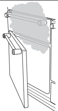
Fig. 1.1
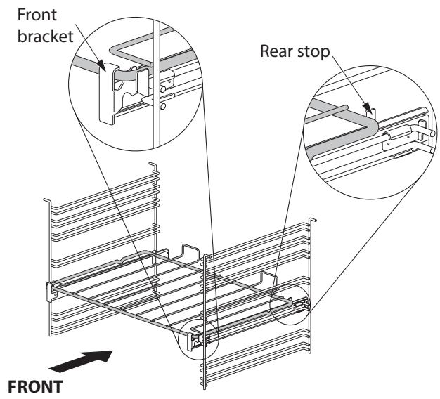
Fig. 1.2
along the back of the cooker) for warming plates, dishes, drying tea towels or softening butter.
- DO NOT use water on grease fires and never pick up a flaming pan. Turn the controls off and then smother a flaming pan on a surface unit by covering the pan completely with a well fitting lid or baking tray. If available, use a multi-purpose dry chemical or foam-type fire extinguisher.
- DO NOT modify this appliance. This appliance is not intended to be operated by means of external timer or separated remote-control system.
- If flammable materials are stored in the drawer, oven(s) or grill(s) it may explode and result in fire or property damage.
- If the supply cord is damaged, it must be replaced by the manufacturer, its service agent or similarly qualified persons in order to avoid a hazard.
Oven Care
- When the oven is not in use and before attempting to clean the cooker always be certain that the control knobs are in the OFF position.
- Use oven gloves to protect your hand from potential burns.
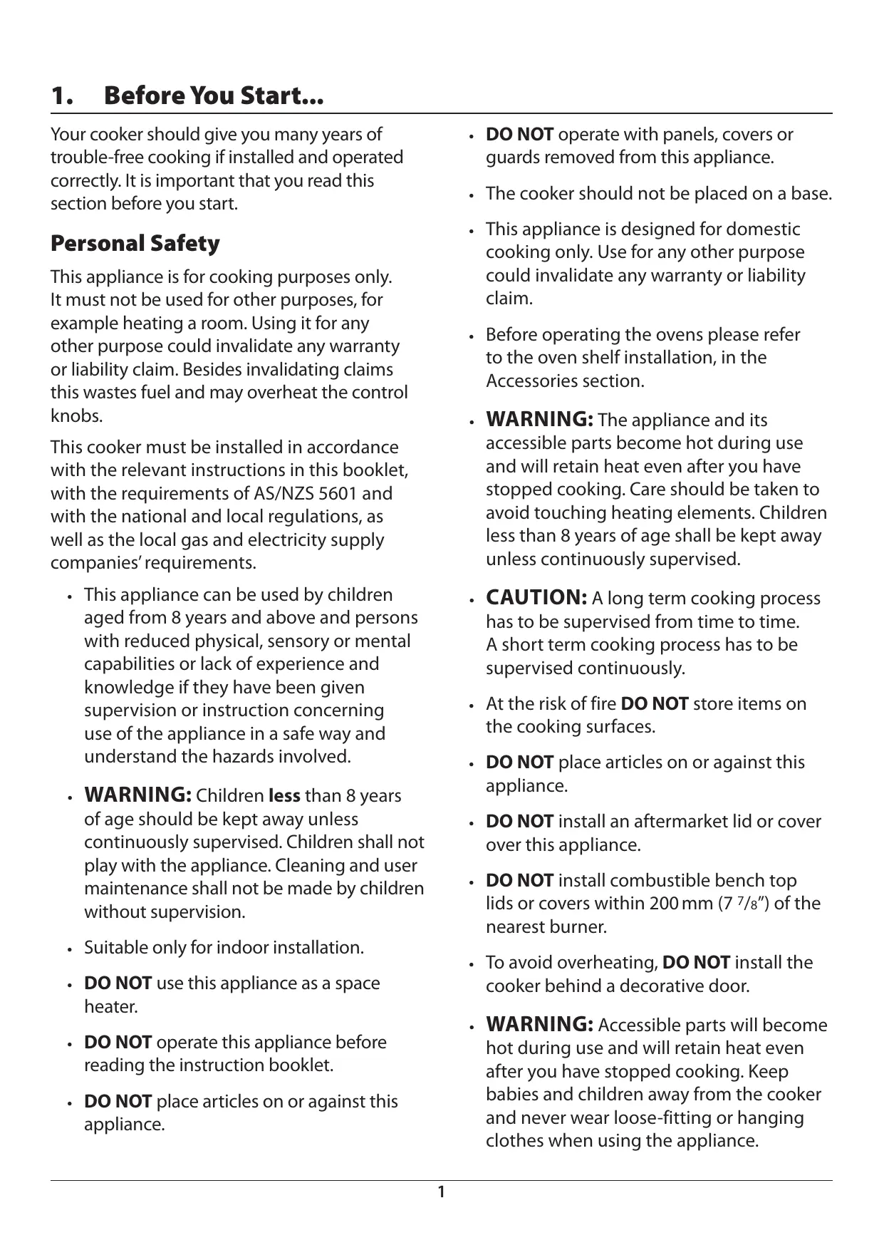
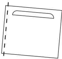
- Cooking high moisture content foods can create a 'steam burst' when the oven door is opened (Fig. 1.1). When opening the oven, stand well back and allow any steam to disperse.
- The inside door face is constructed with toughened safety glass. Take care NOT to scratch the surface when cleaning the glass panel.
- Accidental damage may cause the door glass panel to fracture.
- Keep oven vent ducts unobstructed.
- DO NOT use harsh abrasive cleaners or sharp metal scrapers to clean the oven
door glass since they can scratch the surface, which may result in shattering of the glass.
- Make sure the shelves are pushed firmly to the back of the oven. DO NOT close the door against the oven shelves.
- DO NOT use aluminium foil to cover shelves, linings or the oven roof.
- When the oven is on, DO NOT leave the oven door open for longer than necessary, otherwise the control knobs may become very hot.
- DO NOT use the timed oven if the adjoining oven is already warm.
- DO NOT place warm food in the oven to be timed.
- DO NOT use a timed oven that is already warm.
- Use dry oven gloves when applicable – using damp gloves might result in steam burns when you touch a hot surface.
Oven Shelves (dependant on model)
To fit the glide-out shelf, hook the front of the shelf onto the runners as shown (Fig. 1.2). The rear of the shelf should rest on the runners, in front of the rear stop (Fig. 1.2).
Standard oven shelves can be fitted by lining up the shelf with a groove in the oven ladders. Push the shelf back until the ends hit the shelf stop. Lift the front so the shelf clears the stops, then lower the front so the shelf is level and push it fully back.
Grill/Glide-out Grill™ Care
- When using the grill, make sure that the grill pan is in position and pushed fully in, otherwise the control knobs may become very hot.
- DO NOT leave the grill on for more than a few moments without the grill pan
underneath it, otherwise the knobs may become hot.
- NEVER close the grill door when the grill is on.
- Accessible parts may be hot when the grill is in use. Young children should be kept away
Cooker Care
As steam can condense to water droplets on the cool outer trim of the oven, it may be necessary during cooking to wipe away any moisture with a soft cloth. This will also help to prevent soiling and discolouration of the oven exterior by cooking vapours.
Cleaning
- Isolate the electricity supply before carrying out any thorough cleaning. Allow the cooker to cool.
- In the interests of hygiene and safety, the cooker should be kept clean at all times as a build up in fats and other food stuff could result in a fire.
- Clean only the parts listed in this guide.
- Clean with caution. If a wet sponge or cloth is used to wipe spills on a hot surface, be careful to avoid steam burns. Some cleaners can produce noxious fumes if applied to a hot surface.
- NEVER use paint solvents, washing soda, caustic cleaners, biological powders, bleach, chlorine based bleach cleaners, coarse abrasives or salt.
- DO NOT mix different cleaning products – they may react together with hazardous results.
- All parts of the cooker can be cleaned with hot soapy water.
-
Take care that no water seeps into the appliance.
-
Before you remove any of the grill parts for cleaning, make sure that they are cool or use oven gloves.
- DO NOT use any abrasive substances on the grill and grill parts.
- DO NOT put the side runners in a dishwasher.
- DO NOT put the burner heads in a dishwasher.
- NEVER use caustic or abrasive cleaners as these will damage the surface.
- DO NOT use steel wool, oven cleaning pads or any other materials that will scratch the surface.
- NEVER store flammable materials in the drawer. This includes paper, plastic and cloth items, such as cookbooks, plastic ware and towels, as well as flammable liquids.
- DO NOT store explosives, such as aerosol cans, on or near the appliance.
- DO NOT use steel wool, oven cleaning pads, or any other materials that will scratch the surface.
- DO NOT attempt to disassemble or clean around any burner while another burner is on, otherwise an electric shock could result.
2. Range Overview
Fig. 2.1
The 110 dual fuel cooker (Fig. 2.1) has the following features:
A. 6 hotplate burners including 2 wok burners
B. A control panel
C. A glide-out grill
D. Main multi-function oven
E. Fan oven
F. Storage drawer
Hotplate Burners
The drawing by each of the central knobs indicates which burner that knob controls.
Each burner has a Flame Supervision Device (FSD) that prevents the flow of gas if the flame goes out.
When a hotplate control knob is pressed in, sparks will be made at every burner – this is normal. Do not attempt to disassemble or clean around any burner while another burner is on, otherwise an electric shock could result.
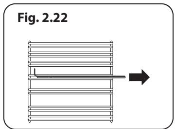
To light a burner, push in the selected burner control knob and turn it to the high position, as indicated by the large flame symbol (A) (Fig. 2.2).
The igniter should spark and light the gas. Keep holding the knob pressed in to let the gas through to the burner for about ten seconds.
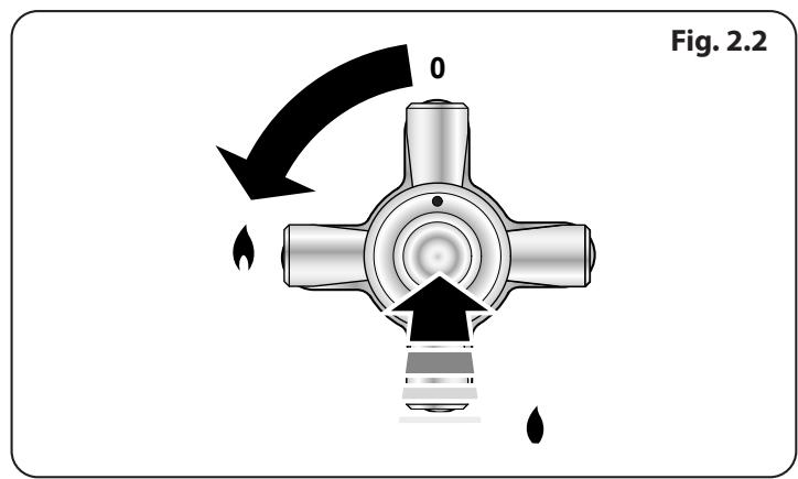
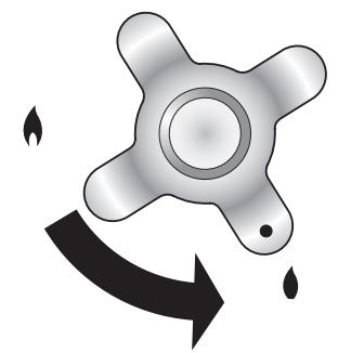
Fig. 2.3
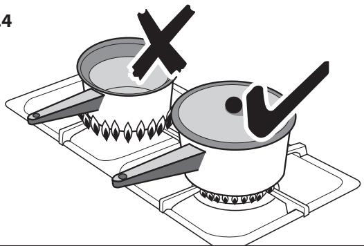
Fig. 2.4
Fig. 2.5
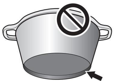
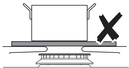
Fig. 2.6
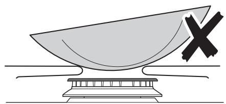
Fig. 2.7
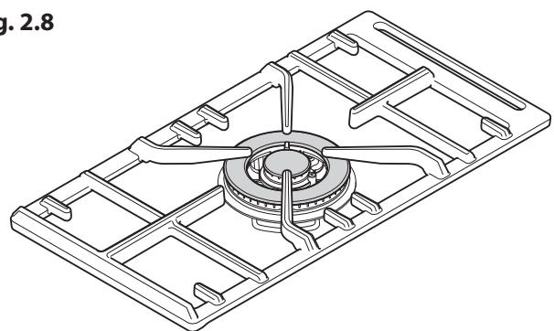
Fig. 2.8
If, when you let go of the control knob the burner goes out, then the FSD has not been bypassed. Turn the control knob to the OFF position and wait for one minute before you try again, this time making sure to hold in the control knob for slightly longer.
Adjust the flame height to suit by turning the knob counterclockwise (Fig. 2.3). On this cooker the low position is beyond high, NOT between high and off.
If a burner flame goes out, turn off the control knob and leave it for one minute before relighting it.
Make sure that the flames are under the pans. Using a lid will help the contents boil more quickly (Fig. 2.4).
Large pans should be spaced well apart.
Pans and kettles with concave bases or down-turned base rims should not be used (Fig. 2.5).
Simmering aids, such as asbestos or mesh mats, are NOT recommended (Fig. 2.6). They will reduce burner performance and could damage the pan supports.
You should also avoid using unstable and misshapen pans that may tilt easily, and pans with a very small base diameter, e.g. milk pans, single egg poachers (Fig. 2.7).
The minimum recommended pan diameter is 120mm . The maximum allowable pan base diameter is 260mm .
DO NOT use cooking vessels on the hotplate that overlap the edges.
Wok Burner
The wok burner is designed to provide even heat over a large area. They are ideal for large pans and stir-frying (Fig. 2.8).
For heating smaller pans, the hotplate burners may be more efficient.
You should wipe the enamel top surface of the cooker around the hotplate burners as soon as possible after spills occur. Try to wipe them off while the enamel is still warm.
NOTE: The use of aluminium pans may cause metallic marking of the pan supports. This does not affect the durability of the enamel and may be cleaned off with an appropriate metal cleaner.
The Wok Cradle
The wok cradle is designed to fit a 35 cm wok. If you use a different wok, make sure that it fits the cradle. Woks vary very widely in size and shape. It is important that the wok sits down on the pan support – however, if the wok is too small, the ring will not support it properly (Fig. 2.9).
The cradle should be used on the wok burners only. When you fit the cradle, check that it is supported properly on a pan support and the wok is sitting level in the cradle (Fig. 2.10). The cradle will get very hot in use – allow plenty of time for it to cool before you pick it up.
The Griddle Plate (optional)
Part number: P052872
The griddle plate fits the centre left pan support, front to back (Fig. 2.11). It is designed for cooking food on directly. DO NOT use pans of any kind on it. The griddle plate surface is non-stick and metal cooking utensils (e.g. spatulas) will damage the surface. Use heat resistant plastic or wooden utensils.

DO NOT put it crossways – it will not fit properly and will be unstable (Fig. 2.12).

DO NOT put it on any other burners – it is not designed to fit in any of the other pan supports.
Position the griddle plate over the hotplate burners resting on the pan support. Check that it is securely located.
The griddle plate can be lightly brushed with cooking oil before use. Light the hotplate burners (Fig. 2.13). Adjust the flame heights to suit.
Preheat the griddle plate for a maximum of 5 minutes before adding food. Leaving it longer may cause damage. Turn the control knobs towards the low position, marked with the small flame symbol, to reduce the burner flames.

Always leave space around the griddle plate for the gases to escape.

NEVER fit two griddle plates side by side (Fig. 2.14).
After cooking, allow the griddle plate to cool before cleaning.
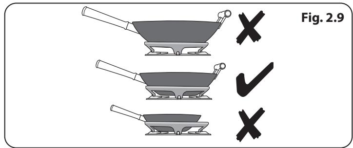
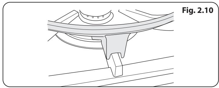
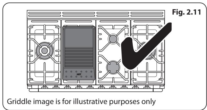
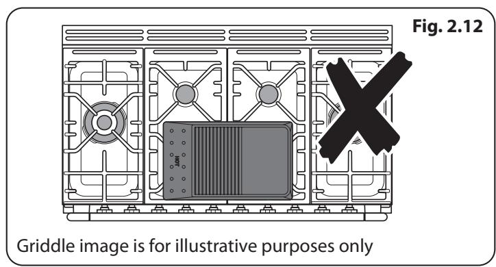
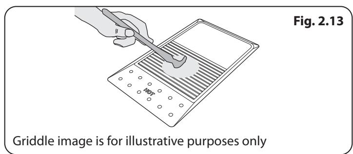
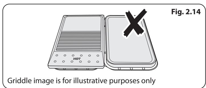
Fig. 2.15
Table 2.1
| Function | Use |
| Defrost | To thaw small items in the oven without heat |
| Fan oven | A full cooking function, even heat throughout, great for baking |
| Fanned grilling | Grilling meat and fish with the door closed |
| Fan assisted | A full cooking function good for roasting and baking |
| Conventional oven | A full cooking function for roasting and baking in the lower half of the oven |
| Browning element | To brown and crisp cheese topped dishes |
| Base heat | To crisp up the bases of quiche, pizza or pastry |
The Glide-out Grill™ (Fig. 2.15)
WARNING: When the trivet has been removed from the grill pan, please ensure that the grill pan and cradle are fully returned into the grill chamber. The grill pan door MUST remain open.
A Accessible parts may be hot when the broiler is in use. Young children should be kept away.
Never close the grill door when the grill is on.
- For best results, slide the carriage back into the grill chamber and preheat the appropriate part(s) of the grill for two minutes. The grill trivet can be removed and the food placed on it while you are waiting for the grill to preheat.
- DO NOT leave the grill on for more than a few moments without the grill pan underneath it, otherwise the knobs may become hot.
- Once the grill has preheated, slide the carriage out again. With the trivet back in place with the food on it, slide the carriage back into the grill chamber. Make sure that it is pushed right in.
The grill pan trivet can be turned to give four grilling heights by a combination of turning it back to front and turning it upside down. See chapter Using the Glide-out Grill™.
The Ovens
References to 'left-hand' and 'right-hand' ovens apply as viewed from the front of the appliance.
The left-hand oven is a multi-function oven, while the right-hand oven is a fan oven.
The Multi-function Oven
As well as the oven fan and fan element, they are fitted with two extra heating elements, one visible in the top of the oven and the second under the oven base. Take care to avoid touching the top element and element deflector when placing or removing items from the ovens.
The multi-function oven has 3 main cooking functions: fan, fan assisted and conventional cooking. These functions should be used to complete most of your cooking.
The browning element and base heat can be used in the latter part of the cooking process to fine tune the results to your particular requirements.
Use fanned grilling for all your grilling needs and defrost to safely thaw small items of frozen food.
Table 2.1 gives a summary of the multi-function modes.
The multi-function ovens have many varied uses. We suggest you keep a careful eye on your cooking until you are familiar with each function. Remember – not all functions will be suitable for all food types.
Please remember that all cookers vary – temperatures in your new ovens may differ to those in your previous cooker.
Multi-function Oven Functions
Defrost

This function operates the fan to circulate cold air only. Make sure the temperature control is at 0^ and that no heat is applied. This enables small items such
as desserts, cream cakes and pieces of meat, fish and poultry to be defrosted.
Defrosting in this way speeds up the process and protects the food from flies. Pieces of meat, fish and poultry should be placed on a rack, over a tray to catch any drips. Be sure to wash the rack and tray after defrosting.
Defrost with the oven door closed.
Large items, such as whole chickens and joints should not be defrosted in this way. We recommend this be carried out in a refrigerator.
Defrosting should not be carried out in a warm oven or when an adjoining oven is in use or still warm.
Make sure that dairy foods, meat and poultry are completely defrosted before cooking.
Fan Oven

This function operates the fan and the heating element around it. An even heat is produced throughout the oven, allowing you to cook large
amounts quickly.
Fan oven cooking is particularly suitable for baking on several shelves at one time and is a good 'all-round' function. It may be necessary to reduce the temperature by approximately 10^ for recipes previously cooked in a conventional oven.
If you wish to preheat the oven, wait until the indicator light has gone out before inserting the food.
Fanned Grilling

This function operates the fan whilst the top element is on. It produces a more even, less fierce heat than a conventional grill. For best results, place the food to
be grilled, on a trivet over a roasting tin, which should be smaller than a conventional grill pan. This allows greater air circulation. Thick pieces of meat or fish are ideal for grilling in this way, as the circulated air reduces the fierceness of the heat from the grill.
The oven door should be kept closed while grilling is in progress, so saving energy.
You will also find that the food needs to be watched and turned less than for normal grilling. Preheat this function before cooking.
For best results we recommend that the grill pan is not located on the uppermost shelf.
Fan Assisted Oven

This function operates the fan, circulating air heated by the elements at the top and the base of the oven. The combination of fan and conventional cooking
(top and base heat) makes this function ideal for cooking large items that need thorough cooking, such as a large meat roast.
It is also possible to bake on two shelves at one time, although they will need to be swapped over during the cooking time, as the heat at the top of the oven is greater than at the base, when using this function.
This is a fast intensive form of cooking; keep an eye on the food cooking until you have become accustomed to this function.
Conventional Oven (Top and Base Heat)

This function combines the heat from the top and base elements. It is particularly suitable for roasting and baking pastry, cakes and biscuits.
Food cooked on the top shelf will brown and crisp faster than on the lower shelf, because the heat is greater at the top of the oven than at the base, as in 'Fan Assisted Oven' function. Similar items being cooked will need to be swapped around for even cooking. This means that foods requiring different temperatures can be cooked together, using the cooler zone in the lower half of the oven and hotter area to the top.
The exposed top element may cook some foods too quickly, so we recommend that the food be positioned in the lower half of the oven to cook. The oven temperature may also need to be lowered.
Browning Element

This function uses the element in the top of the oven only. It is a useful function for the browning or finishing of pasta dishes, vegetables in sauce,
shepherds pie and lasagne, the item to be browned being already hot before switching to the top element.
Base Heat

This function uses the base element only. It will crisp up your pizza or quiche base or finish off cooking the base of a pastry case on a lower shelf. It is also a
gentle heat, good for slow cooking of casseroles in the middle of the oven or for plate warming.
The Browning and Base Heat functions are useful additions to your oven, giving you flexibility to finish off items to perfection.
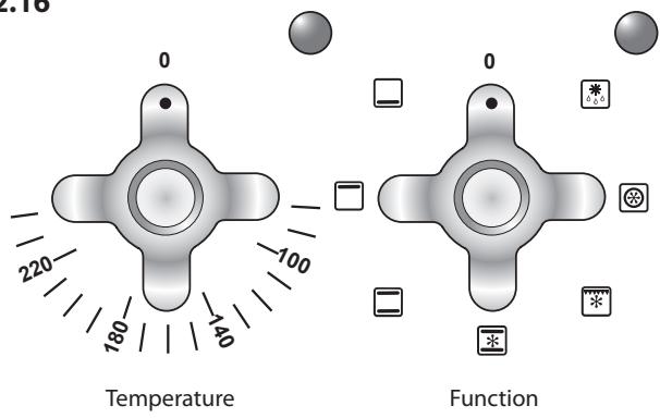
Fig.2.16
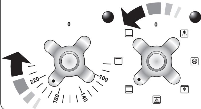
Fig. 2.17
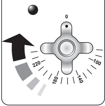
Fig. 2.18
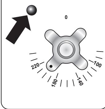
Fig. 2.19
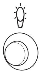
Fig. 2.20
The Fan Oven
The right-hand oven is a fan oven that circulates hot air continuously, which means faster, more even cooking.
The recommended cooking temperatures for a fan oven are generally lower than a conventional oven.
NOTE: Please remember that all cookers vary so temperatures in your new ovens may differ to those in your previous cooker.
Operating the Ovens
Operating the Multi-function Oven
The multi-function oven has two controls: a function selector and a temperature setting knob (Fig. 2.16).
Turn the function selector control to a cooking function. Fig. 2.17 shows the control set for convectional oven cooking.
Turn the oven temperature knob to the temperature required (Fig. 2.18).
The oven heating light will glow until the oven has reached the temperature you selected. It will then cycle on and off during cooking as the oven maintains the selected temperature (Fig. 2.19).
Operating the Fan Oven
Turn the oven knob to the desired temperature (Fig. 2.18).
The oven indicator light will glow until the oven has reached the temperature selected. It will then cycle on and off during cooking (Fig. 2.19).
Main Oven Light
Press the button to turn the lights on (Fig. 2.20).
If an oven light fails, turn off the power supply before changing the bulb. See the 'Troubleshooting' section for details on how to change the bulb.
Accessories
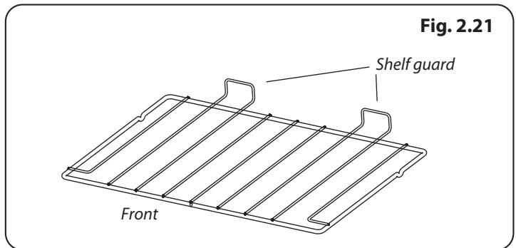
Oven Shelves
The oven shelves (Fig. 2.21) are retained when pulled forward but can be easily be removed and refitted.
Pull the shelf forwards until the back of the shelf is stopped by the shelf support (Fig. 2.22).
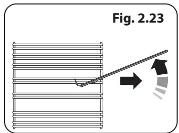
Lift up the front of the shelf so the back of the shelf will pass under the shelf stop and then pull the shelf forward (Fig. 2.23).
To refit the shelf, line up the shelf with a groove in the oven side and push the shelf back until the ends hit the shelf stop. Lift up the front so the shelf ends clear the shelf stops, and then lower the front so that the shelf is level and push it fully back.
Telescopic runners - Left-hand (Main) Oven
As well as standard shelves, the left-hand oven is supplied with a set of runners for a glide-out oven shelf.
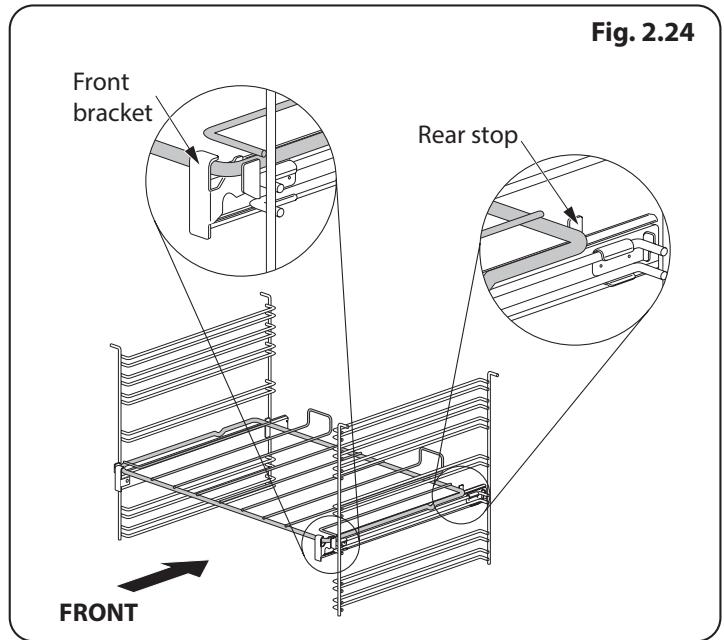
To fit the glide-out shelf, hook the front of the shelf onto the runners as shown (Fig. 2.24). The rear of the shelf should rest on the runners, in front of the rear stop (Fig. 2.24).
The glide-out shelf and runners can be easily removed or repositioned.
To remove the glide-out shelf
Raise the rear of the shelf, so that it clears the rear stops. Then unhook from the front locating bracket.
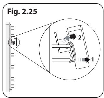
To remove the glide-out runners
Twist to unclip the base of the runners from the shelf supports. Then unhook the runner from the top rung of the shelf support and remove (Fig. 2.25).
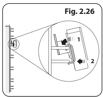
To refit the glide-out runners
Hook the rear of the runner over the top rung of a pair of shelf supports. Then hook the front of the runner onto the same rung. Push to clip under the bottom rung (Fig. 2.26).
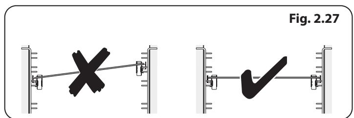
Ensure that the shelf runners are fitted in the same position on each side (Fig. 2.27).
The front of the shelf runners can be identified by the bracket (Fig. 2.24).
DO NOT put the glide-out shelf runners in a dishwasher.
Storage
The bottom drawer is for storing oven trays and other cooking utensils. It can get very warm, so do not store anything in it that may melt or catch fire.
The drawer can be removed completely by pulling it right out and up.
3. Using the Glide-out Grill™
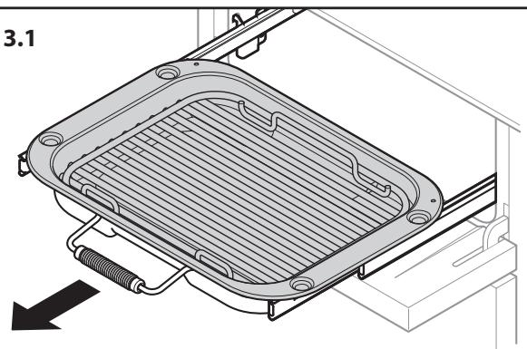
Fig. 3.1
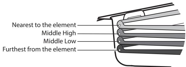
Fig. 3.2
Four grill height positions
refer to Fig. 3.5
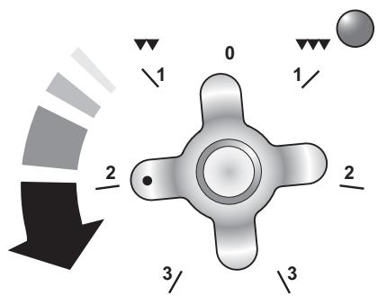
Fig. 3.3
To switch on the right half element
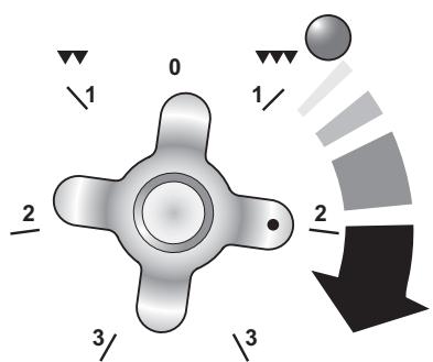
Fig. 3.4
To switch on both elements
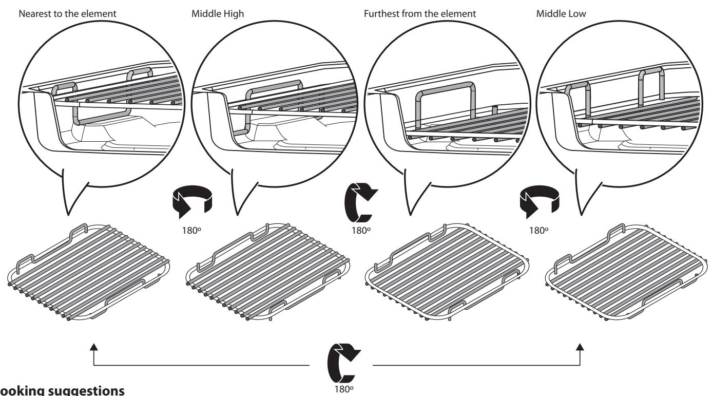
Four grill height positions
Fig. 3.5
- Nearest to the element - loast, streaky bacon.
- Middle high - cheese on toast, welsh rarebit, courgette slices, back bacon.
3.Middle low -fish fillets, vegetable skewers. - Furthest from the element - whole fish, thick pork chops, chicken breasts, chicken or beef skewers.
NOTE: A short term cooking process has to be supervised continuously.
5. Cooking tips
Cooking with a multifunction oven
Remember: not all modes are suitable for all food types. The oven cooking times given are intended for a guide only.
General oven tips
The wire shelves should always be pushed firmly to the back of the oven.
Baking trays with food cooking on them should be placed level with the front edge of the oven's wire shelves. Other containers should be placed centrally.
Keep all trays and containers away from the back of the oven, as overbrowning of the food may occur.
For even browning, the maximum recommended size of a baking tray is:
depth: 340mm (1338^ ) by width: 340mm (1338^ )
When the oven is on, do not leave the door open for longer than necessary, otherwise the knobs may get very hot.
- Always leave a "finger's width" between dishes on the same shelf. This allows the heat to circulate freely around them.
- To help keep your oven clean, cover meat when roasting, with foil or use a roasting bag.
- To reduce fat splashing when you add vegetables to hot fat around a roast, dry them thoroughly or brush lightly with cooking oil.
- Where dishes may boil and spill over during cooking, place them on a baking tray.
- If you want to brown the base of a pastry dish, preheat the baking tray for 15 minutes before placing the dish in the centre of the tray.
6. Cooking Table
The oven control settings and cooking times given in the table below are intended to be used as a guide only. Individual tastes may require the temperature to be altered to provide a preferred result.
Food is cooked at lower temperature in a fan oven than in a conventional oven. When using recipes, reduce the fan oven temperature by 10^ and the cooking time by 5-10 minutes. The temperature in the fan oven does not vary with height in the oven so you can use any shelf.
Top (T)
Centre (C)
Base (B)
Oven Shelf Positions
| Food | Conventional Oven °C (Shelf Position) | Fan Oven Temperature | Approximate Cooking Time | |
| Meat | ||||
| Beef (no bone) | 160 (C) | 150 °C | 30-35 minutes per 500g +30-35 minutes. | Thoroughly thaw frozen joints before cooking. Meat may be roasted at 220°C (210°C for fan oven) and the cooking time adjusted accordingly. For stuffed and rolled meats, add approximately 10 minutes per 500g, or cook at 200°C (190°C) for 20 minutes then 160°C (150°C) for the remainder. |
| 200 (C) | 190 °C | 20-25 minutes per 500g +20-25 minutes. | ||
| Lamb | 160 (C) | 150 °C | 30-35 minutes per 500g +30-35 minutes. | |
| 200 (C) | 190 °C | 25-30 minutes per 500g +25-30 minutes. | ||
| Pork | 160 (C) | 150 °C | 35-40 minutes per 500g +35-40 minutes. | |
| 200 (C) | 190 °C | 25-30 minutes per 500g +25-30 minutes. | ||
| Poultry | 160 (C) | 150 °C | 20-25 minutes per 500g +20-25 minutes. | For stuffed poultry, you could cook at 200°C (190°C) for 20 minutes then 160°C (150°C) for remainder. Do not forget to include the weight of the stuffing. For fresh or frozen pre-packed poultry, follow instructions on the pack. |
| Chicken | 200 (C) | 190 °C | 15-20 minutes per 500g +15-20 minutes. | |
| 160 (C) | 150 °C | 20 minutes per 500g +20 minutes. | ||
| Turkey | 200 (C) | 190 °C | 15 minutes per 500g +15 minutes. | |
| 160 (C) | 150 °C | 25-30 minutes per 500g. | ||
| Duck | 200 (C) | 190 °C | 20 minutes per 500g. | Thoroughly thaw frozen poultry before cooking. |
| Casserole | 140-150 (C) | 130 °C-140 °C | 2-4 hours according to recipe. | |
| Yorkshire Pudding | 220 (C) | 210 °C | Large tins 30-35 minutes; individual 10-20 minutes. | |
| Cake | ||||
| Very rich fruit - Christmas, wedding, etc. | 140 (C/B) | 130 °C | 45-50 minutes per 500g of mixture. | Using the conventional oven: When two tier cooking leave at least one runner space between shelves. Position the baking tray with the front edge along the front of the oven shelf. |
| Fruit 180 mm tin | 150 (C/B) | 140 °C | 2-2½ hours. | |
| Fruit 230 mm tin | 150 (C/B) | 140 °C | Up to 3½ hours. | |
| Madeira 180 mm | 160 (C/B) | 150 °C | 80-90 minutes. | |
| Queen cakes | 190 (C/B) | 180 °C | 15-25 minutes. | |
| Scones | 220 (C/B) | 210 °C | 10-15 minutes. | Up to three tiers can be cooked on, in a fan oven, at the same time. But make sure to leave at least one runner space between each shelf being cooked on. |
| Victoria sandwich | ||||
| 180 mm tin | 180 (C/B) | 170 °C | 20-30 minutes. | |
| 210 mm tin | 180 (C/B) | 170 °C | 30-40 minutes. | |
| Desserts | ||||
| Shortcrust tarts | 200 (C/B) | 190 °C | 20-30 minutes on a preheated tray. | |
| Fruit pies | 200 (C/B) | 190 °C | 35-45 minutes. | |
| Tartlets | 200 (C/B) | 190 °C | 10-20 minutes according to size. | Up to three tiers can be cooked on, in a fan oven, at the same time. But make sure to leave at least one runner space between each shelf being cooked on. |
| Puff pastry | 210 (C/B) | 200 °C | 20-40 minutes according to size. | |
| Meringues | 100 (C/B) | 90 °C | 2-3 hours. | |
| Baked egg custard | 160 (C/B) | 150 °C | 45-60 minutes. | |
| Baked sponge pudding | 180 (C/B) | 170 °C | 40-45 minutes. | |
| Milk pudding | 140-150 (C/B) | 130 °C-140 °C | 2 to 3 hours. | |
| Bread | 210 (C) | 200 °C | 20-30 minutes. | |
| Fish | Fanned Grilling | |||
| Fillet | 190 (C/B) | 190 °C (C/B) | 15-20 minutes | |
| Whole | 190 (C/B) | 190 °C (C/B) | 15-20 minutes per 500g. | |
| Steak | 190 (C/B) | 190 °C (C/B) | Steaks according to thickness. |
7. Cleaning your cooker
Essential information
Isolate the electricity supply before carrying out any thorough cleaning. Allow the cooker to cool.

NEVER use paint solvents, washing soda, caustic cleaners, biological powders, bleach, chlorine based bleach cleaners, coarse abrasives or salt.

DO NOT mix different cleaning products - they may react together with hazardous results.
All parts of the cooker can be cleaned with hot soapy water – but take care that no surplus water seeps into the appliance.
Remember to switch on the electricity supply and reset the clock before re-using the cooker.
Hotplate burners
Some models have a separate trim ring, which fits on the burner head.
The burner heads and caps can be removed for cleaning.

DO NOT put the burner heads in a dishwasher.
Make sure they are absolutely dry before replacing them.
The Single Ring Burners
When refitting the burner head, make sure that the notch lines up with the electrode or hole in the base. Check that the burner head is level and that the cap is fitted centrally on the burner head (Fig. 7.1).
The Wok Burner
The Wok burner can also be taken apart for cleaning.
When reassembling the wok burner (Fig. 7.2), turn over the large base ring and find the 'D' shaped area (Fig. 7.3). Turn the head until the 'D' matches the one on the burner base. Flip the burner over once again and place it on the burner base.
Check the burner slots are not blocked. If a blockage occurs, remove stubborn particles using a toothbrush (Fig. 7.4).
Now fit the two burner caps, ensuring that they are seated properly.
Check the burner ports are not blocked. If a blockage occurs, remove stubborn particles using a piece of fuse wire.
The Wok Cradle
Recommended cleaning materials are hot soapy water, a moistened soap pad, cream cleaner or a nylon scourer.
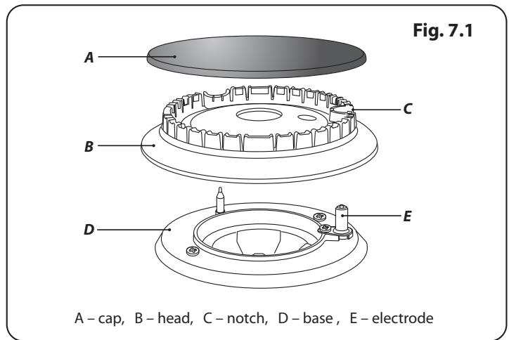
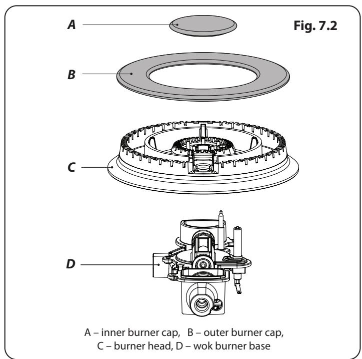
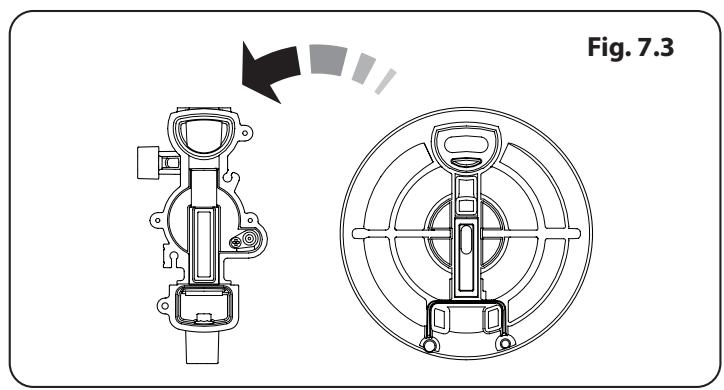
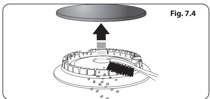
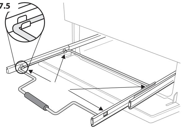
Fig. 7.5
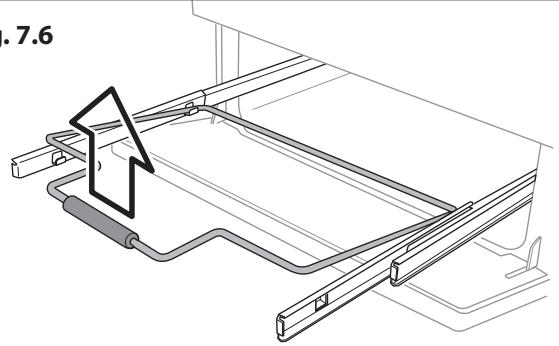
Fig. 7.6
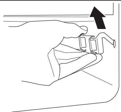
Fig. 7.7
The Griddle (optional)
Always clean the griddle after use. Allow it to cool completely before removing. Immerse the griddle plate in hot soapy water. Use a soft cloth or, for stubborn stains, a nylon washing up brush.
NOTE: If the griddle is washed in a dishwasher then some dishwasher residue may appear on the back. This is normal and will not affect the performance of your griddle.
Glide-out Grill
The grill pan and trivet should be washed in hot soapy water. Alternatively, the grill pan can be washed in a dishwasher.
After grilling meats or any foods that soil, leave to soak for a few minutes in the sink immediately after use. Stubborn particles may be removed from the trivet using a nylon brush.

Before you remove any of the grill parts for cleaning. make sure that they are cool, or use oven gloves.

DO NOT use any abrasive substances.
Cleaning the Glide-out Grill
The grill pan can be easily removed for cleaning as follows:
Remove the grill pan support frame by pulling the grill pan forward.
Lift the grill pan clear of the support frame. The support frame is held to the side rails by two clips on each side (Fig. 7.5).
For each side, support the side rail with one hand and with the other hand lift the frame up and out of the side clips (Fig. 7.6).
For safety, push the side rails back into the grill chamber.
If you need to remove the side rails to allow cleaning of the grill chamber, you can unhook them from the grill chamber sides (Fig. 7.7) and wipe the sides clean with a soft cloth and mild detergent.

DO NOT put the side runners in a dishwasher.
Once you have finished, hook the side rails back onto the sides of the chamber. To refit the frame, pull the side rails forward and, for each side in turn, support the side rail and press the frame down into the side rails. Replace the grill pan
Control panel and doors
Avoid using any abrasive cleaners including cream cleaners, on brushed stainless steel surfaces. For best results, use a liquid detergent.
The control panel, knobs and doors should only be cleaned with a soft cloth wrung out in clean hot soapy water – but take care that no surplus water seeps into the appliance.
After cleaning, polish with a dry cloth.
Glass fronted door panels
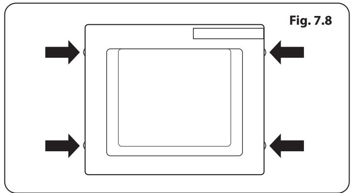
The oven door front panels can be taken off so that the glass panels can be cleaned. Move the cooker forward to gain access to the sides (see the 'Moving the Cooker' section under 'Installation').
Open the oven door slightly and remove the front panel fixing screws from the door sides, two each side (Fig. 7.8).
Carefully lift off the outer door panel. The inside face of the glass panels can now be cleaned – take care not to disturb or wet the door insulation.
NOTE: If the door is triple glazed then the inner two panels are fixed together and should not be separated.
After cleaning, carefully refit the outer door panel and replace the side fixing screws.

DO NOT use harsh abrasive cleaners or sharp metal scrapers to clean the oven door glass since they can scratch the surface, which may result in shattering of the glass.
Ovens
'Cook & Clean' Panels
The main oven has panels which have been coated with a special enamel that partly cleans itself. This does not stop all marks on the lining, but helps to reduce the amount of manual cleaning needed.
The Cook & Clean panels work better above 200^ . If you do most of your cooking below this temperature, occasionally remove the panels and wipe with a lint free cloth and hot soapy water. The panels should then be dried and replaced and the oven heated at 200^ for about one hour. This will make sure that the Cook & Clean panels are working effectively.

DO NOT use steel wool, oven cleaning pads, or any other materials that will scratch the surface.
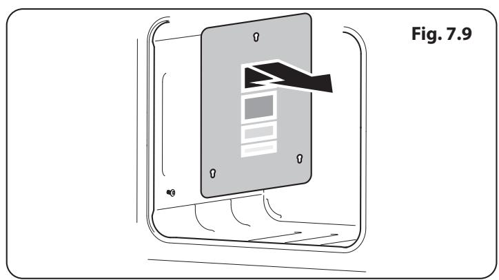
Removing the main oven linings
Some of the lining panels can be removed for cleaning.
If you wish to clean the enamel interior of the oven, you will need to remove the shelves before removing the 'Cook & Clean' panels. You do not have to remove the support brackets to remove the panels. Lift each panel upward and slide forward off the support brackets (Fig. 7.9).
Once the panels have been removed, the oven enamel interior can be cleaned.
Refit in the reverse order.
Cleaning table
Cleaners listed are available from supermarkets or electrical retailers as stated.
For enamelled surfaces use a cleaner that is approved for use on vitreous enamel.
Regular cleaning is recommended. For easier cleaning, wipe up any spillages immediately.
| Hotplate | ||
| Part | Finish | Recommended Cleaning Method |
| Hob top (including burner heads and caps) | Enamel, stainless steel, aluminium | Hot soapy water, soft cloth. Any stubborn stains remove gently with a nylon scourer. |
| Ceramic/Induction hob | Toughened glass | Hot soapy water; cream cleaner/scourer if necessary. |
| Griddle plate (some models only) | Non-stick surface | Allow to cool. Wash in hot soapy water. Do not use abrasive cleaners/ scourers. Dishwasher. |
| Warming zone (some models only) | Toughened glass | Hot soapy water, cream cleaner/scourer if necessary. |
| Outside of Cooker | ||
| Part | Finish | Recommended Cleaning Method |
| Door, door surround and storage drawer exterior | Enamel or paint | Hot soapy water, soft cloth. Any stubborn stains, remove gently with a liquid detergent. |
| Stainless steel | E-cloth (electrical retailers) or microfibre all-purpose cloth (supermarket). | |
| Sides and plinth | Painted surface | Hot soapy water, soft cloth. |
| Splashback/rear grille | Enamel or stainless steel | Hot soapy water, soft cloth. Cream cleaner, with care, if necessary. |
| Control panel | Paint, enamel or stainless steel | Warm soapy water. Do not use abrasive cleaners on lettering. |
| Control knobs/handles & trims | Plastic/chrome, copper or lacquered brass | Warm soapy water, soft cloth. |
| Brass | Brass polish. | |
| Oven door glass/glass lid | Toughened glass | Hot soapy water, cream cleaner/scourer if necessary. |
| Oven and Grill | ||
| Part | Finish | Recommended Cleaning Method |
| Sides, floor & roof of oven NOT COOK & CLEAN OVEN PANELS (see below) | Enamel | Any proprietary oven cleaner that is suitable for enamel. CAUTION: CORROSIVE/CAUSTIC OVEN CLEANERS: FOLLOW MANUFACTURER'S INSTRUCTIONS. Do not allow contact with the oven elements. |
| Cook & Clean oven panels (some models only) | Special enamel that partly cleans itself | This surface cleans itself at 200 °C and above, or the panels can be removed and washed with hot soapy water and a nylon brush (see 'The Ovens' in 'Cleaning your Cooker'). |
| Oven shelves, Handyrack, Grill trivet, Handygrill rack | Chrome | An oven interior cleaner that is suitable for chrome. Soap filled pad. Dishwasher. |
| Grill pan/meat tin (some models only) | Enamel | Hot soapy water. Soap filled pad. Dishwasher. |
7. Troubleshooting
Hotplate/Cooktop ignition or hotplate burners faulty
Is the power on? If not, there maybe something wrong with the power supply.
Are the sparker (ignition electrode) or burner slots blocked by debris (Fig. 7.1, Fig. 7.2, Fig. 7.3, Fig. 7.4)?
Are the burner trim and caps correctly located? See the section on 'Cleaning'.
Hotplate/Cooktop burners will not light
Make sure that the burner parts have been replaced correctly after wiping or removing for cleaning.
Check that there is not a problem with your gas supply. You can do this by making sure that other gas appliances you may have are working.
Do the burners spark when you push the button?
Steam is coming from the oven
When cooking foods with high water content (e.g. oven fries) there may be some steam visible at the rear grille.
Take care when opening the oven door, as there may be a momentary puff of steam when the oven door is opened. Stand well back and allow any steam to disperse.
What cleaning materials are recommended for the cooker?
See the 'Cleaning' section for recommended cleaning materials.

Never use caustic or abrasive cleaners as these will damage the surface.
An oven fan is noisy
The note of the oven fan may change as the oven heats up – this is perfectly normal.
If there is an installation problem and I don't get my original installer to come back to fix it who pays?
You do. Service organizations will charge for their call outs if they are correcting work carried out by your original installer. It is in your interest to track down your original installer.
Poor performance
In the unlikely event that, after installation, the appliance does not perform correctly please contact your distributor ("Service and Spares" page 20)
Food is cooking too slowly, too quickly, or burning
Cooking times may differ from your previous oven.
Check that you are using the recommended temperatures and shelf positions – see the oven cooking guide. The oven control settings and cooking times are intended to be used only as a guide.
Individual tastes may require the temperature to be altered either way, to get the results you want.
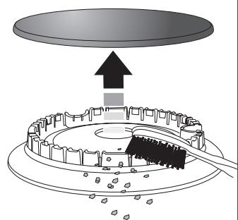
Fig. 7.1
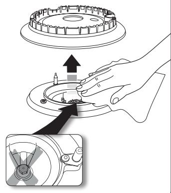
Fig. 7.2
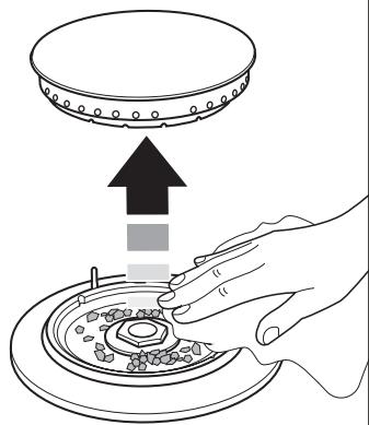
Fig. 7.3
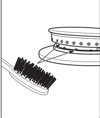
Fig. 7.4
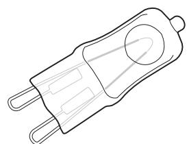
Fig. 7.5
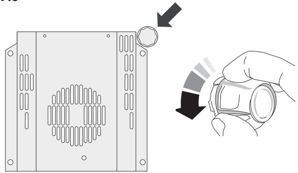
Fig. 7.6
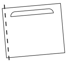
Fig. 7.7
Effect of hinge adjustment - exaggerated for clarity
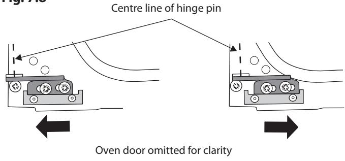
Fig. 7.8
The oven is not cooking evenly.
Do not use a baking tray with dimensions larger than those specified in the section on 'General Oven Tips'.
If you are cooking a large item, be prepared to turn it round during cooking.
If two shelves are used, check that space has been left for the heat to circulate. When a baking tray is put into the oven, make sure that it is placed centrally on the shelf.
Check that the door seal is not damaged and that the door catch is adjusted so that the door is held firmly against the seal.
A dish of water when placed on the shelf should be the same depth all over. (For example, if it is deeper at the back, then the back of the cooker should be raised up or the front lowered.) If the cooker is not level, arrange for your supplier to level it for you.
Oven not coming on
Is the power on? If not, there may be something wrong with the power supply.
Is the cooker supply on at the isolator switch?
Oven temperature getting hotter as the cooker gets older
If turning the temperature down using the oven control knob has not worked, or has only worked for a short time, then you may need a new thermostat. This should be fitted by a qualified service person.
Oven light is not working
The bulb has probably burnt out. You can buy a replacement bulb (which is not covered under the warranty) from a good electrical shop.
Ask for a 40W - 230V halogen lamp (G9) (Fig. 7.5).
Turn off the power at the circuit breaker.
Before removing the existing bulb, turn off the power supply and make sure that the oven and bulb have cooled. Open the oven door and remove the oven shelves.
Remove the bulb cover by turning it a quarter turn, counterclockwise. It may be very stiff (Fig. 7.6).
Taking care to protect your fingers with a glove in case the bulb should shatter, unscrew the old bulb.
Screw in the new bulb; screw back the bulb cover. Turn on the circuit breaker and check that the bulb now lights.
The oven door is misaligned
The bottom hinge of either oven door can be adjusted to alter the angle of the door (Fig. 7.7). Loosen the bottom hinge fixing screws and use the notch and a flat bladed screwdriver to move the position of the hinge to set the hinge position (Fig. 7.8).
Retighten the hinge screws.
Grill
The fascia gets hot when I use the oven or grill
The cooker is cooled by a fan. If the fascia becomes excessively hot when the cooker is in use then the cooling fan may have failed. Should this occur please contact your installer, a qualified repair engineer or Customer Service to arrange for its repair.
The knobs get hot when I use the oven or the grill. Can I avoid this?
Yes, this is caused by heat rising from the oven or the grill, and heating them up. DO NOT leave the oven door open.
Make sure that the grill pan is pushed right back to the 'back stop' when grilling.
Always grill with the grill compartment door open.
Grill is not cooking properly
Are you using the pan and trivet supplied with the cooker?
Is the pan being used on the runners, not the floor of the grill compartment?
Is the grill tray pushed back fully to the stop?
INSTALLATION
Check the appliance is electrically safe when you have finished.
7. Service and Spares
Firstly, please complete the appliance details below and keep them safe for future reference – this information will enable us to accurately identify the particular appliance and help us to help you. Filling this in now will save time and inconvenience if you later have a problem with the appliance. It may also be of benefit to keep your purchase receipt with this leaflet. You may be required to produce the receipt to validate a warranty field visit.
| Distributor's Name and Address | Andi-Co Australia Pty Ltd. 1 Stamford Road, Oakleigh, VIC 3166 Customer Care Tel: 1300 650 020 Email: service@andico.com.au |
| Name of Appliance | |
| Appliance Serial Number* | |
| Fuel Type | |
| Date of Purchase | |
| Installer's Name, Address and Telephone No. | |
| Date of Installation |
- This information is on the appliance data badge.
If You Have a Problem
In the unlikely event that you have a problem with your appliance, please refer to rest of this booklet, especially the problem solving section, first to check that you are using the appliance correctly.
If you are still having difficulty, contact Customer Care on 1300 650 020 or email service@andico.com.au.
Please Note
For warranty information and how to request a remedy, please refer to the Warranty Statement at https://www.andico.com.au/warranty/ or contact Customer Care.
Out of Warranty
We recommend that our appliances are serviced regularly throughout their life to maintain the best performance and efficiency. The frequency of service will depend on usage – for normal usage once a year should suffice.
Service work should only be carried out by a suitably Authorised Person.
Spare Parts
To maintain optimum and safe performance, we recommend that only genuine spare parts are used. Do not use re-conditioned or unauthorised controls. Contact Spare Parts on (03) 9569 7744 or email spares@andico.com.au
INSTALLATION
Check the appliance is electrically safe when you have finished.
9. Installation
Location of cooker
The cooker may be installed in a kitchen/kitchen diner but NOT in a room containing a bath or shower.
This appliance is designed for domestic cooking only. Use for any other purpose could invalidate any warranty or liability claim.
NOTE: An appliance for use on LPG must not be installed in a room or internal space below ground level, e.g. in a basement.
Conversion
This appliance is supplied set for G20 20 mbar Cat II _2H3+ .
A conversion kit for another gas is available for the cooker.
If the appliance is to be converted to another gas we recommend that this is carried out before installation.
After converting the appliance, please attach the Gas Conversion sticker over the appropriate area of the data badge – this will identify the gas type for which the appliance is now set.
You will need the following equipment to complete the cooker installation satisfactorily:
- Stability bracket: If the cooker is to be supplied with gas through a flexible hose, a stability bracket or chain MUST be fitted. These are not supplied with the cooker but are available at most builders' merchants.
Gas pressure tester/manometer. - Flexible gas hose: Must be in accordance with the relevant standards.
- Multimeter: For electrical checks.
You will also need the following tools:
- Electric drill
- Masonry drill bit (only required if fitting the cooker on a stone or concrete floor)
- Wall plugs (only required if fitting the cooker on a stone or concrete floor)
- Steel tape measure
- Cross head screwdriver
- Flat head screwdriver
- Spirit level
- Pencil
- Adjustable spanner
- Allen keys (supplied)
- Screws for fitting stability bracket
- 13 mm spanner or socket wrench
| 4 pan supports | Wok cradle |
| Griddle (Optional) | Grill pan & trivet |
| 4 flat shelves with 2 set of runners | Handyrack (Optional) |
| Roasting tin | Plinth |
| Stability location bracket | Allen Keys |
| Conduit box | Stability bracket |
| Restraining chain & hook * |
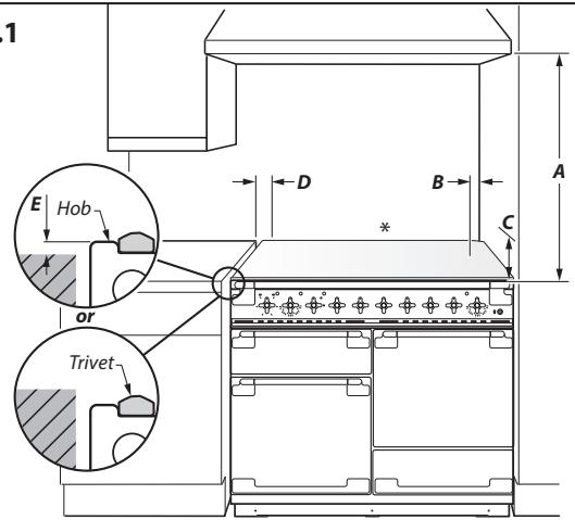
Fig. 9.1

Horizontal combustible surface
Positioning the Range
The diagram (Fig. 9.1) shows the minimum recommended distance from the cooker to nearby surfaces as given in AS/NZS 5601.
1. Overhead - Measurement A
The minimum height of any surface above the cooker is 650mm above the hotplate.
Cookerhoods and exhaust fans shall be installed in accordance with the manufacturer's instructions. However, in no case shall the clearance between the highest part of the hob of the cooking appliance and a cookerhood be less than 650mm or, for an overhead exhaust fan, 750mm .
2. Side Clearances - Measurements B & C
Where B, measured from the periphery of the nearest burner to any vertical combustible surface is less than 200mm , the surface shall be protected by one of the following methods:
a. Fixing ceramic tiles with a minimum thickness of 5mm to the surface.
b. Fixing toughened glass with a minimum thickness of 5mm to the surface, provided the glass is approved by the manufacturer to be suitable for the application.
c. Attaching fire resistant material to the surface and covering with sheet metal with a minimum thickness of 0.4mm .
Protection should be to a height C of not less than 150mm above the hob for the full dimension (width or depth) of the cooking surface area.
3. Side Clearances - Measurement D & E
Where D, the distance from the periphery of the nearest burner to a horizontal combustible surface is less than 200mm , then E shall be 10mm or more, or the horizontal surface shall be above the trivet.
If the horizontal surface is above the trivet, then any vertical combustible surface needs to be protected in accordance with B above.
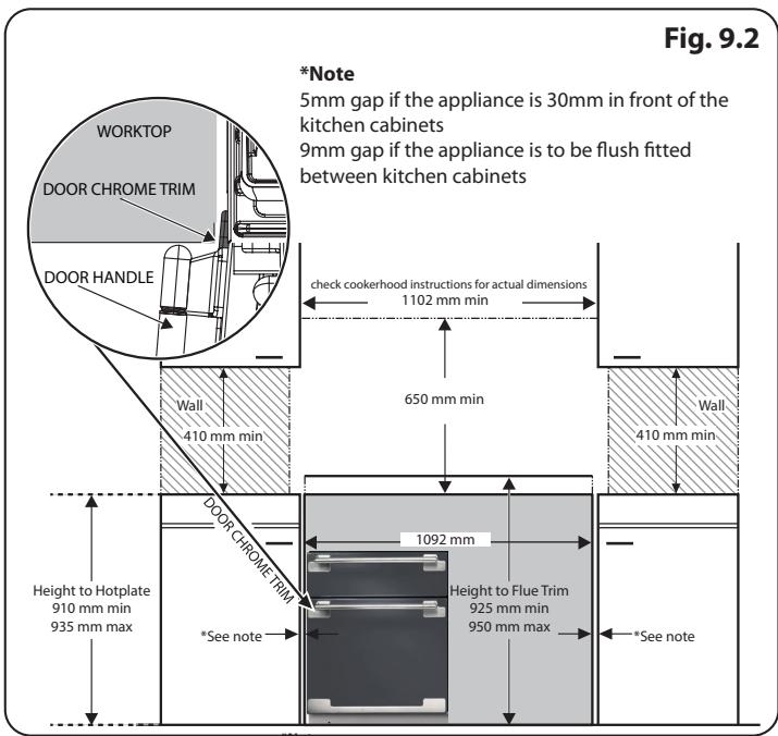
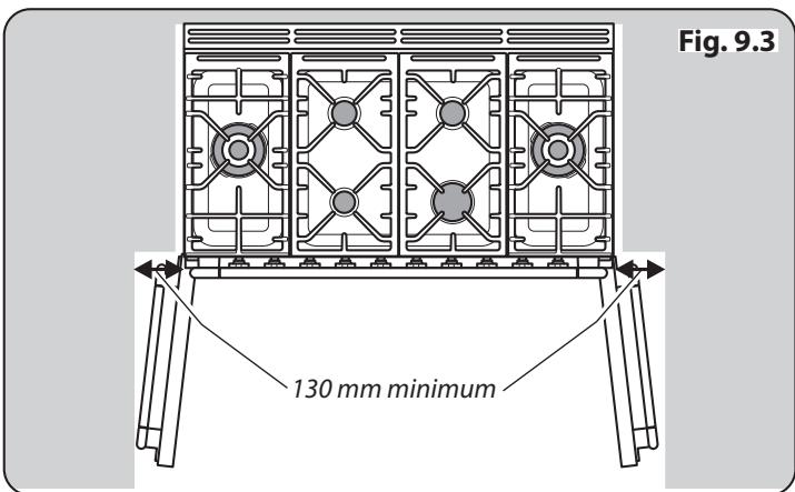
If the cooker is near a corner of the kitchen, a clearance of 130mm is required to allow the oven doors to open (Fig. 9.2 and Fig. 9.3) The actual opening of the doors is slightly less, but this allows for some protection of your hand as you open the door.
We recommend a gap of 910mm between units to allow for moving the cooker. Do not box the cooker in it must still be possible to move the cooker in and out for cleaning and servicing.
INSTALLATION
Check the appliance is electrically safe when you have finished.
When Fitting Between Kitchen Cabinets
We recommend that you either:
A. Fit the range so that any cabinet doors are at least 30 ~mm behind the range door fronts. Note that this may require an infill piece behind the range. We recommend a gap of 1102 ~mm between units to allow for moving the range. DO NOT box the range in – it must be possible to move the range in and out for cleaning and servicing.
B. Leave a gap of at least 9mm on either side of the range (a 1110mm gap between units) (Fig. 9.2 and Fig. 9.3). The range should be positioned centrally.
We also recommend that you DO NOT final fix any adjacent cabinets until the range is installed. Decorative mouldings or handles on cabinet doors and fronts may interfere with the opening of the oven doors.
Moving the cooker
A On no account try and move the cooker while it is plugged into the electricity supply.
The cooker is very heavy, so take extra care.
We recommend that two people manoeuvre the cooker. Make sure that the floor covering is firmly fixed, or removed, to prevent it being disturbed when moving the cooker around.
To help you, there are two levelling rollers at the back, and two screw-down levelling feet at the front.
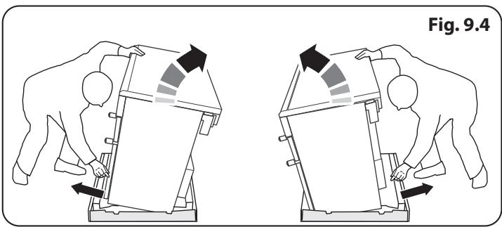
Remove the polystyrene base pack. From the front, tilt the cooker backwards and remove the front half of the polystyrene base (Fig. 9.4).
Repeat from the back and remove the rear half of the polystyrene base.
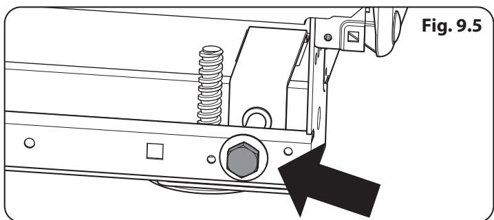
Lowering the two rear rollers
To adjust the height of the rear of the cooker, first fit a 13mm spanner or socket wrench onto the hexagonal adjusting nut (Fig. 9.5). Rotate the nut - clockwise to raise - counterclockwise to lower.
Make 10 complete (360^) turns clockwise.
Make sure you lower BOTH REAR ROLLERS.
INSTALLATION
Check the appliance is electrically safe when you have finished.
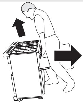
Fig. 9.6

Fig. 9.7
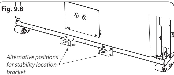
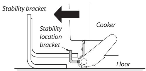
Fig. 9.9
Typical floor mounting
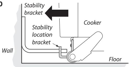
Fig. 9.10
Typical wall mounting
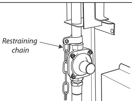
Fig. 9.11
Completing the move
Unfold the rear edge of the cardboard base tray. Open the oven door(s) so that you can get a good grip on the bottom of the fascia panel as you move the oven (Fig. 9.6).
Carefully push the cooker backwards off the base tray. Remove the base tray.
Position the cooker close to its final position, leaving just enough space to get behind it (Fig. 9.7).

DO NOT use the door handles or control knobs to manoeuvre the cooker.
Levelling
You are recommended to use a spirit level on a shelf in one of the ovens to check for level.
Place the cooker in its intended position, taking care not to twist it within the gap between the kitchen units as damage may occur to the cooker or the units.
The front feet and rear rollers can be adjusted to level the cooker. To adjust the height of the rear of the cooker turn the adjusting nuts at the front bottom corners of the cooker. To set the front feet turn the bases to raise or lower.
Fitting a Stability Bracket
When fitting a stability bracket (Fig. 9.8) please refer to the instructions supplied with the bracket for further details on fitting.
When fitting a stability bracket (Fig. 9.9 and Fig. 9.10) adjust the bracket to give the smallest practicable clearance between the bracket and the engagement slot in the rear of the cooker.
Fit the bracket so that it engages as far as possible over the chassis of the cooker.
Caution, possibility of tilting
Anti-tip restraints
Fitting the Restraining Chain
The restraining chain MUST be fitted.
The length of chain between the appliance and the wall fixing should prevent strain on the gas and electricity connections, but still allow access to unhook the chain when the cooker is pull forward.
Measure the length of chain required. Use the clamp supplied to clamp onto the gas pipe (Fig. 9.11). Fix the supplied hook securely to the wall.
INSTALLATION
Check the appliance is electrically safe when you have finished.
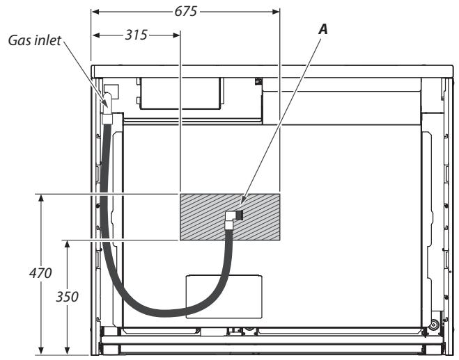
Fig. 9.12
All dimensions in millimetres
Repositioning the cooker following connection
If you need to move the cooker once it has been connected then you need to unplug it and, having gripped under the fascia panel and lifted the front of the cooker slightly
(Fig. 9.6), you need to check behind the cooker to make sure that the gas hose is not caught.
As you progress, make sure that both the electricity cable and gas hose always have sufficient slack to allow the cooker to move.
With a stability chain fitted, release it as you ease the cooker out. DO NOT forget to refit it when you replace the cooker.
When you replace the cooker, again check behind to make sure that the electricity cable and gas hose are not caught or trapped.
Gas Connection
This must be in accordance with the relevant standards.
The gas supply needs to terminate with a down-facing threaded fitting 12 connection. The inlet connector is located just below the hotplate level at the rear of the cooker.
Because the height of the cooker can be adjusted and each connection is different, it is difficult to give precise dimensions. Ideally the hose supply connection should be within the shaded area 'A' (Fig. 9.12).
Means of isolation must be provided at the supply point by either an approved quick-connect device or a Type 1 manual shut-off valve.
The hose should be fitted so that both inlet and outlet connections are vertical so that the hose hangs downwards in a 'U' shape.
A flexible connection is supplied with the cooker. If it is necessary to use another hose it must be to AS 1869 class B and be suitable for your gas type.
If in doubt contact your supplier. Screw connect the threaded end of the hose into the gas inlet.
After completing the gas connection, check the cooker is gas sound with a pressure test. When checking for gas leaks do not use washing up liquid – this can corrode. Use a product specifically manufactured for leak detection.
Natural Gas
The gas pressure regulator is preset to give a nominal pressure of 1kPa on Natural Gas. Connect to the Rp~12 inlet on the underside of the pressure regulator.
Propane
This cooker is supplied ready for use on natural gas. A conversion kit for Propane as is supplied with the cooker - see the 'Conversion to Propane Gas' section.
Pressure Testing
The pressure test point is accessible on the inlet pipe at the rear. Remove the test nipple screw and fit a pressure gauge to the test point. Turn on and light two of the hotplate burners.
For Natural Gas cookers the operating pressure should be 1kPa .
For Propane X cookers the operating pressure should be 2.54kPa
Pressure Testing
The gas pressure can be measured at one of the hotplate burner injectors (not a wok burner).
Lift off a burner head. Fit the pressure gauge to the injector.
Turn on and light one of the other hotplate burners.
Turn on the control knob for the burner with the pressure gauge fitted to let gas through.
See the data badge for test pressures.
Turn off the burners. Make sure that you reassemble the burner top in the correct way on the burner body.
Electrical Connection
This appliance must be installed by a qualified electrician to comply with current AS/NZS 3000 Wiring Rules and regulations in force.
Make sure that the mains characteristics (voltage, nominal, power, etc.) match the ratings indicated on the data plate affixed to the cooker.
The cooker is preset for a single-phase earthed electrical connection. It is essential to install a multi-pole circuit breaker that completely disconnects the appliance from the mains, with a minimum contact break distance of 3mm .

WARNING: THIS APPLIANCE MUST BE EARTHED.
The appliance must be connected to an efficient earthing circuit. If the electricity network is not equipped with an earth connection, then it must be installed separately in compliance with local regulations.
Earthing is a safety measure required by law, and must be performed with particular care by a qualified technician, who must also check that the electricity supply characteristics are correct.
See the Technical Data section for information on the total electrical load of the appliance. The cable size used should be suitable for this load and comply with all local requirements (i.e. PVC Insulated cable IEC 60227 - code 53 for ordinary cables).
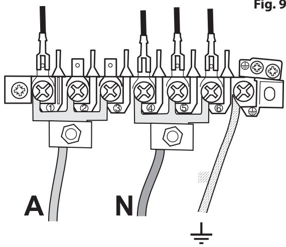
Access to the mains terminal is gained by removing the electrical terminal cover box on the back panel. Connect the mains cable to the correct terminals for your electrical supply type (Fig. 9.13 and Fig. 9.14). Check that the links are correctly fitted and that the terminal screws are tight. Secure the mains cable using the cable clamp.
Current Operated Earth Leakage Breakers
The combined use of your cooker and other domestic appliances may cause nuisance tripping, so we recommend that the cooker is protected on an individual RCD (Residual Current Device) or RCBO (Residual Current Breaker with Overload).
IF IN DOUBT, PLEASE CONSULT A SUITABLY QUALIFIED ELECTRICIAN.
Fig. 9.13
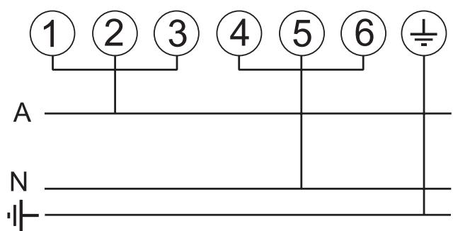
1-phase 230V_AC50Hz
INSTALLATION
Check the appliance is electrically safe when you have finished.


An isolation switch shall be provided and mounted near the cooker, in a readily accessible position, in compliance with AS/NZS 3000 and/or AS/NZS 5601 as applicable for the appliance configuration.
Note: The marking for the rated current of the fuse protecting a socket should be placed on or near the socket outlet.
Connection in New Zealand
Type of cord in accordance with IEC 60227 with a minimum rating of 90^ .
Cord size recommended for this application is 3 × 10 ~mm^2 , three-core cable (Power cables may be sized to take into account the coincidence factor AS/NZS 60335.2.6:2014).
Rating of the plug is 32 Amp, in accordance with AS/NZS 3112. Based on the arithmetic mean value when measured under full load stabilized conditions, Clause 10 IEC 60335-1.
If this cooking range is to be connected to a new or upgrade electrical installation, then it must be connected to the supply by a supply cord fitted with:
An appropriately rated plug that is compatible with the socket - outlet fitted to the final sub -circuit in the fixed wiring that supplies this cooking range
OR
- An appropriately rated installation male connector that is compatible with the installation female connector fitted to the final sub circuit in the fixed wiring that supplies this cooking range.
Note: The marking for the rated current of the fuse protecting a socket should be placed on or near the socket outlet.
Fixed Wiring
Disconnect from the mains supply.
For connection to fixed wiring, i.e. flexible conduit, Remove the electrical terminal cover on the back panel (Fig. 9.15).
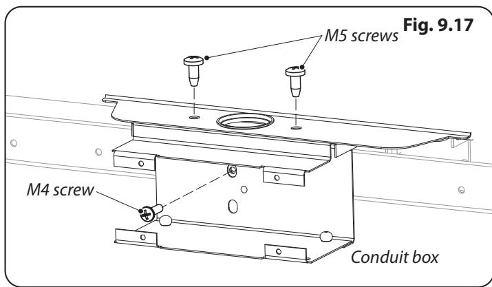
Remove the M4 screw securing the reducer plates to the conduit box (Fig. 9.16). Fit the conduit box to the cooker using the two M5 screw fittings located at the top of the box and the M4 screw (Fig. 9.17).
The conduit box cover is reversible. Fit the reducer plates, if required (Fig. 9.18). Feed the cable through the conduit box and secure in place with the cable clamp.
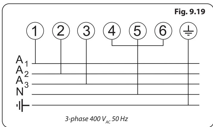
Connect the mains cable to the correct terminals for your electrical supply type (Fig. 9.19). Check that the links are correctly fitted and that the terminal screws are tight.
Fit the cover to the conduit box.
INSTALLATION
Check the appliance is electrically safe when you have finished.
Repositioning the cooker following connection
If you need to move the cooker once it has been connected then you need to unplug it and, having gripped under the fascia panel and lifted the front of the cooker slightly
(Fig. 9.6), you need to check behind the cooker to make sure that the electricity cable is not caught.
As you progress, make sure that the electricity cable always has sufficient slack to allow the cooker to move.
When you replace the cooker, again check behind to make sure that the electricity cable is not caught or trapped.
10. Final Fitting
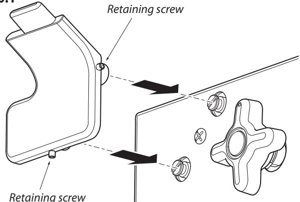
Fig. 10.1
Fig. 10.2
10.2
Retaining screw
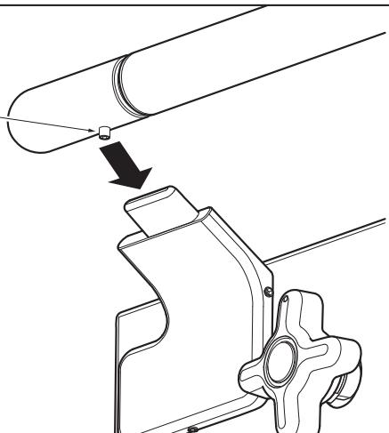
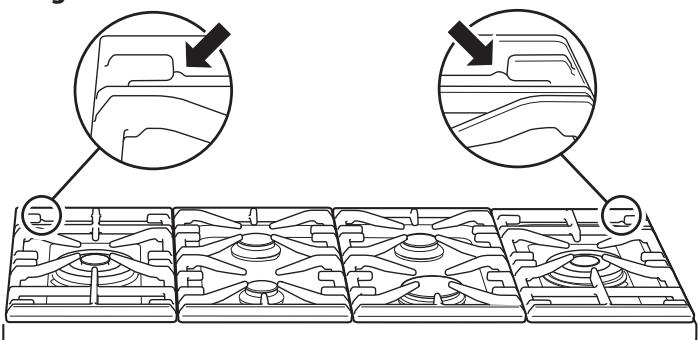
Fig. 10.3
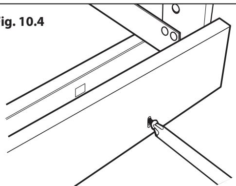
Fig. 10.4
Fitting the Handrail
- Using the 2mm Allen key supplied, loosen the two retaining screws in the base and side of the handrail support. Fit the handrail support onto the locating bosses on the fascia (Fig. 10.1).
NOTE: The handle support should face upwards.
- Push the support back against the fascia and tighten the one retaining screws. Repeat for the other side. Check that each support is secure.
- Locate the handrail onto the support tabs and, using the 3 mm Allen key supplied, tighten the one retaining screws in the bottom to secure (Fig. 10.2).
Fitting the Pan Supports
Please note that the outer pan supports are handed, and may prevent the centre pan supports from fitting correctly. There is a small indent in the rear of each of the outer supports. This indent should be towards the outer edge of the cooker (Fig. 10.3).
Fitting the Plinth
Remove the three screws for the plinth mounts along the front bottom edge of the cooker (Fig. 10.4). Fasten the plinth using these screws.
Final Checks
After completing installation check operation of the appliance:
Hob Check
Check each cooking zone in turn. Be sure to use pans of the correct size and material.
Grill Check
Turn on the grill control and check that the grill heats up.
Oven Check
Turn on the oven. Check the oven fans start to turn and that the oven heats up.
Customer Care
Installer: Please complete your details in this guide, inform the user how to operate the cooker and hand over the instructions.
11. Conversion to LP Gas
Conversion from Natural Gas
(1.0 kPa) to LPG X Propane
(2.54 kPa)
A suitably competent person must perform the conversion. After conversion the installation must comply with the relevant regulations and also the local electricity supply company requirements. Read the instructions before converting this appliance.
Failure to convert the appliance correctly could invalidate any warranty or liability claims and lead to prosecution.
When servicing or replacing gas-carrying components disconnect from the gas supply before starting operation. Check the appliance is gas sound after completion.
DO NOT use reconditioned or unauthorised gas controls.
Disconnect from the electricity and gas supply before conversion.
Before electrical reconnection, check that the appliance is electrically safe.
Hotplate
Injectors
Remove the burner caps and heads. Remove the old jets (Fig. 11.1). Fit the new jets (see the 'Technical Data' section at the back of this book for the correct jets). Reassemble in reverse order.
Bypass Screw Adjustment
Removing the Control Panel
Pull off all the control knobs. Remove the handrail (Fig. 11.2). Using a 2mm Allen key, undo the 2 retaining screws in the base and side of each handrail support and remove.
Remove the 3 fixing screws (A) from the underside of the control panel (Fig. 11.3). Remove the 2 screws (B) that were hidden by the handrail supports. Lift the control panel clear, taking care not to damage or strain the wiring.
Bypass Screw Adjustment
Turn the bypass screw on each control clockwise to the stop (Fig. 11.4).
Refit the control panel. Locate the holes in the top edge on the tags on the inner panel and replace the fixing screws in the bottom edge.
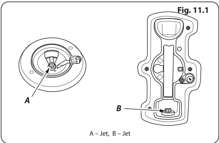
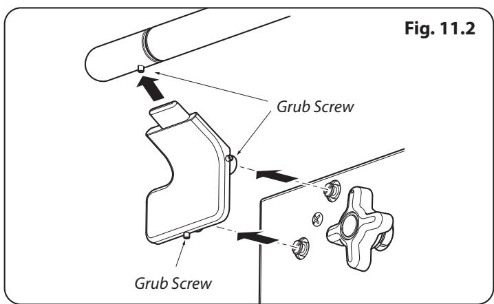
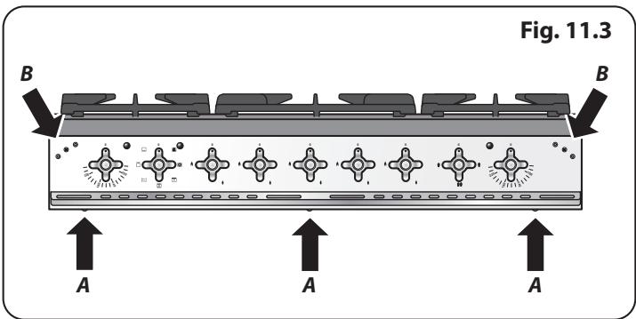
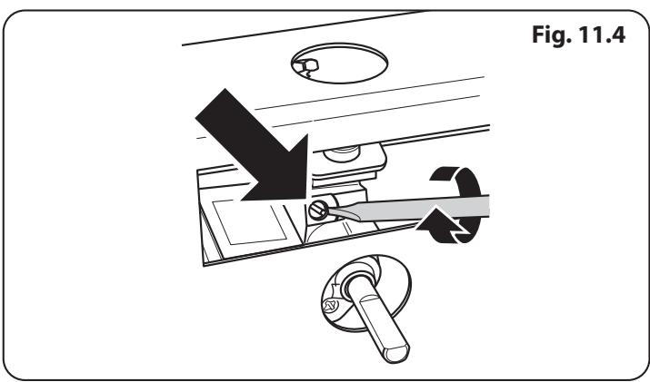
Fig. 11.5
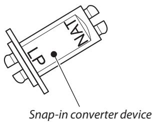

Fig. 11.6

Set the Governor
Unscrew the governor's brass top. In the base of the brass top is a plastic snap-in converter device (Fig. 11.5). To convert the governor, snap the device out of the top and refit it the other way round. The snap-in converter device is marked to show the gas for which it is set (Fig. 11.6).
Make sure the device is secure in the top cap and refit the cap to the governor.
Pressure Testing
The pressure test point is accessible on the inlet pipe at the rear. Remove the test nipple screw and fit a pressure gauge to the test point. Turn on and light two of the hotplate burners.
For Propane X cookers the pressure should be 2.54kPa

Check the appliance is gas sound.

Check operation of all the burners.
Affix Label
- Stick the appropriate gas label over the natural gas part of the appliance data label.
12. Servicing
BEFORE SERVICING ANY GAS CARRYING COMPONENTS TURN OFF THE GAS SUPPLY
A Check the appliance is gas sound after completion of service. When checking for gas leaks do not use washing up liquid – this can corrode. Use a product specifically manufactured for leak detection.
A Do not use reconditioned or unauthorised gas controls.
4 Disconnect from the electricity supply before servicing, particularly before removing any of the following: control panel, side panels, hotplate tray or any electrical components or covers.
Before electrical reconnection, check that the appliance is electrically safe.
1 Panels
1.1 To Remove the Control Panel
DISCONNECT FROM THE ELECTRICITY SUPPLY.
Pull off all the control knobs. Remove the handrail (Fig. 12.1). using a 2mm Allen key, undo the 2 retaining screws in the base and side of each handrail support and remove.
Remove the 3 fixing screws (A) from the underside of the control panel (Fig. 12.2). Remove the 2 screws (B) that were hidden by the handrail supports. Lift the control panel clear, taking care not to damage or strain the wiring.
Disconnect the wiring from the rear. Re assemble in the reverse order when replacing the leads refer to the wiring diagram.
1.2 To Remove the Side Panels
DISCONNECT FROM THE ELECTRICITY SUPPLY.
Remove the control panel (see 1.1). Pull the cooker forward. Remove the 4 retaining screws for each panel (1 at the front base, 1 on the top and 2 at the rear).
Reassemble in the reverse order.
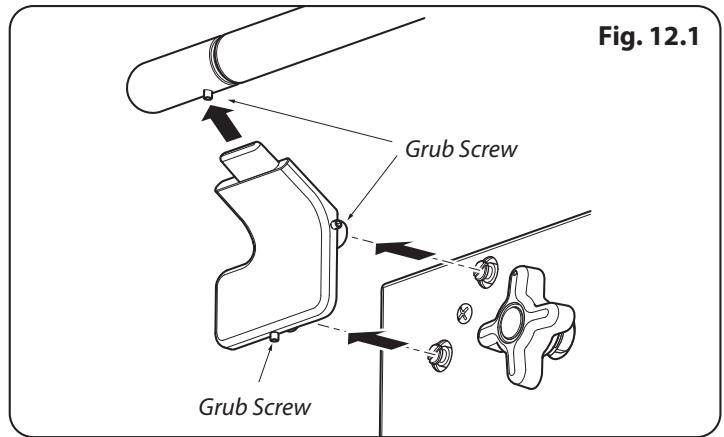
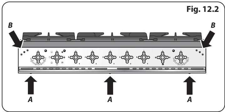
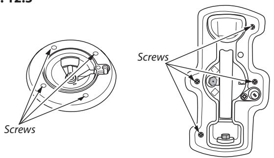
Fig. 12.3
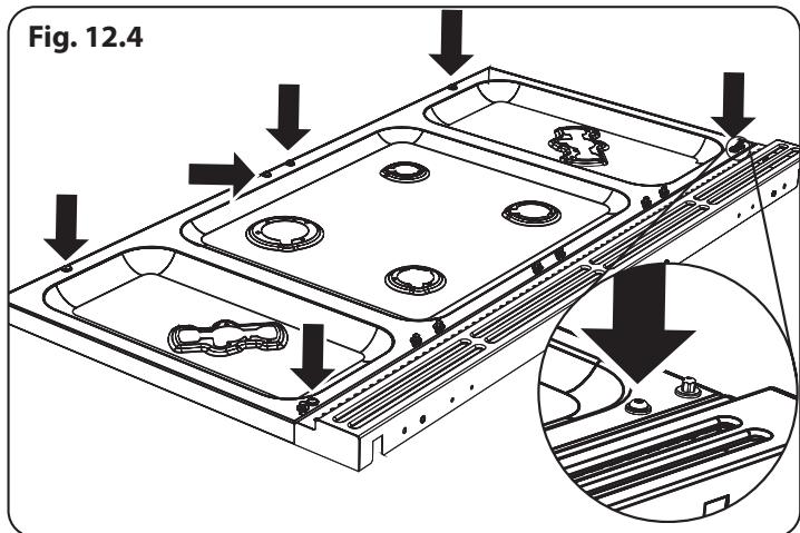
Fig. 12.4
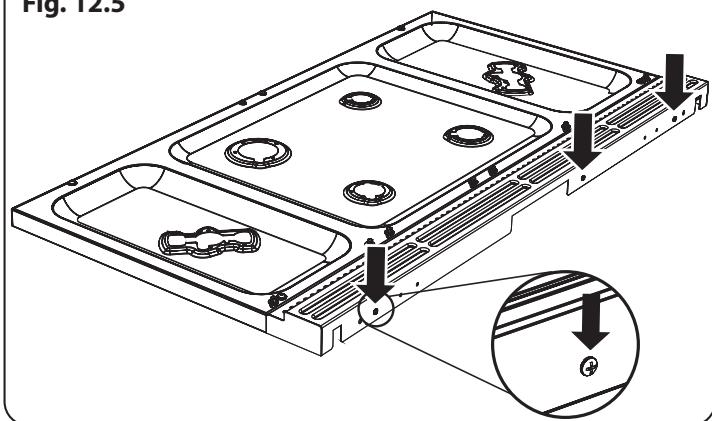
Fig. 12.5
2 Hotplate
2.1 To remove the hotplate

BEFORE SERVICING ANY GAS CARRYING COMPONENTS, TURN OFF THE GAS SUPPLY.

DISCONNECT FROM THE ELECTRICAL SUPPLY!
Remove the pan supports and burner heads.
Remove the screws holding the hotplate burners to the hotplate Fig. 12.3
Remove the 6 screws holding the hotplate tray to the cooker. Fig. 12.4. Pull the range forward to gain access to rear.
Pull the range forward to gain access to the rear.
Remove the 4 screws holding the flue trim at back of cooker Fig.12.5
Taking care not to damage the burner electrodes, carefully lift and withdraw the hotplate.
Reassemble in the reverse order ensuring that the leads are reconnected. Take care not to damage the ignition electrode of the wok burner.
2.2 To Replace the Hotplate Control Taps

DISCONNECT FROM THE ELECTRICITY SUPPLY.

BEFOREServICINGANYGASCARRYING COMPONENTS,TURNOFFTHEGASSUPPLY.
Remove the control panel and hotplate (see 1.1 & 2.1). Unplug the FSD lead from the rear of the tap. Undo the compression fitting at the rear of the tap and remove the fixings that secure the tap to the gas rail. Disconnect the ignition switch wiring.
Remove the tap. Remove and discard the gasket seal. Fit the new gasket seal to the replacement tap. Reassemble in reverse order. Check that the appliance is gas sound. Verify the hotplate ignition.
2.3 To Change a Hotplate Burner Injector
Remove the burner cap and head. Remove the old injector.
Fit the new injector. Reassemble in the reverse order. Check the appliance is gas sound.
2.4 To Replace a Hotplate Burner Electrode

DISCONNECT FROM THE ELECTRICITY SUPPLY.
Lift off pan supports and remove the burner cap. Remove the screw holding the electrode. Pull the electrode vertically up sufficiently to grip the lead between thumb and forefinger.
Pull off the electrode, but keep hold of the lead. Fit the new electrode to the lead. Fix the electrode in the burner with screw. Replace the burner cap.
Check the burner ignition. Replace the pan supports.
2.5 To Replace a Hotplate Burner

DISCONNECT FROM THE ELECTRICITY SUPPLY.
Remove the hotplate tray (see 2.1). The burners (except the wok burner) are mounted on support struts. For these burners, disconnect the burner feed pipes at the burner. Remove the screws at the front and rear holding the support struts. Lift the strut and burners clear. The burners are fixed to the support struts with 2 screws. Remove the appropriate burner and fit the new one.
Reassemble in reverse order. Check that the burner operation is satisfactory.
Wok Burner
Disconnect the burner feed pipes at the burner.
Fit the new one and reassemble in reverse order. Check that the burner operation is satisfactory.
2.6 To Change a Hotplate Burner Thermocouple

DISCONNECT FROM THE ELECTRICITY SUPPLY.
Remove the control panel and hotplate (see 1.1 & 2.1).
Unplug the FSD lead from the rear of the tap.
The thermocouple sits in a hole that has a slot at one side. Ensure that the thermocouple is cool. Turn the thermocouple so that the earth lead (no sleeve) is in line with the slot. Lift the thermocouple clear of the hole.
Reassemble in reverse order.
3 Controls
3.1. To Replace the Ignition or Light Switch

DISCONNECT FROM THE ELECTRICITY SUPPLY.
Remove the control panel (see 1.1).
NOTE: The old switch may be destroyed during removal. Remove the old switch from its bezel by gripping the switch body behind the control panel and twisting sharply. Remove the switch bezel by folding back the locking wings and pushing forward.
To fit the new bezel to the control panel: first line up the raised key on its body with the cut-out in the control panel and push it in from the front.
Assemble the new switch to the bezel by lining up the key sections and pushing home. Fit the new button by pushing in from the front.
Replace the control panel in the reverse order and test for correct operation.
4 Grill
4.1 To Replace the Grill Controller

DISCONNECT FROM THE ELECTRICITY SUPPLY.
Remove the control panel and hotplate (see 1.1 & 2.1). Disconnect the wiring from controller. Remove the 2 screws holding the controller to the mounting panel.
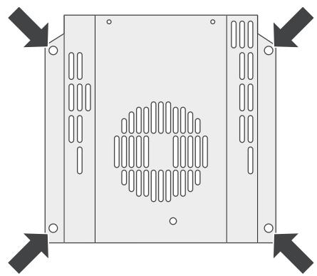
Fig. 12.6
Fit the new controller and reassemble in the reverse order. Check for correct operation.
4.2 To Replace the Grill Element

DISCONNECT FROM THE ELECTRICITY SUPPLY.
Remove the grill pan from the grill chamber. From inside the grill compartment, undo the 2 screws and washers and remove the enamelled front shield from the grill roof. Remove 2 screws and washers securing the grill element front support. Remove the screws from the grill elements.
Carefully lift the elements out and disconnect the leads from the element terminals, noting their position.
If it is not possible to disconnect the leads in this way, pull cooker forwards to gain access to the rear.
Remove the screws securing the electric cover to the back sheet, and then remove cover and disconnect the terminals from the rear.
Fit the new elements and reassemble in reverse order. Check the operation of the grill.
5 Ovens
5.1 To Replace an Oven Thermostat

DISCONNECT FROM THE ELECTRICITY SUPPLY.
Remove the control panel and hotplate (see 1.1 & 2.1). Open the oven door and remove the oven furniture.
For the right-hand oven, remove the thermostat phial cover (2 screws). Unclip the thermostat phial from the clips in the oven back. For the left-hand oven, pull cooker forward to gain access to the cover box at the rear of the cooker. Remove the 4 screws securing the cover and lift clear.
Feed the thermostat capillary out of the oven. Disconnect the wiring from the thermostat. Remove 2 screws holding thermostat to mounting panel. Fit new thermostat and reassemble in the reverse order. Make sure that the phial is clipped to the oven back with the phial centrally positioned between the clips.
Check the operation of the thermostat.
5.2 To Remove an Oven Inner Back
Open the oven door. Remove the 4 screws and washers securing the inner back to the back of the oven (Fig. 12.6).
Carefully lift away the inner back.
Reassemble in reverse order, making sure that you fully tighten the 4 screws and washers.
5.3 To Change the Fan in the Right-hand Oven

DISCONNECT FROM THE ELECTRICITY SUPPLY.
Pull the cooker forward to gain access to the rear. Remove the screws securing the electric cover to the back sheet and remove the cover. Disconnect the 3 terminals connected to the fan, noting their position.
Remove the oven inner back (see 5.2). Hold the fan blade and remove the centre nut (left-hand thread), 2 brass washers, fan blade and circlip. Unscrew the fan retaining nuts and washers (3 off each) and lift the fan away from the rear of the cooker.
Fit the new fan and reassemble in reverse order. Check the operation of the oven.
5.4 To Remove an Oven Element Thermal Cut-out

DISCONNECT FROM THE ELECTRICITY SUPPLY.
Pull the cooker forwards to gain access to the cover box. Undo the cover screws and lift clear.
The cut-out is located on the earth plate beside the oven element connections. Disconnect the cut-out wiring. Undo the fixings that secure the cut-out to the earth plate and remove.
Fit the replacement control and re-assemble in reverse order.
5.5 To Remove the Right-hand Oven Element

DISCONNECT FROM THE ELECTRICITY SUPPLY.
Remove the oven inner back (see 5.2).
Remove the 2 screws from the top of the element and the 1 from the bottom of the element (Fig. 12.7). Carefully lift the element out, disconnecting the terminals connected to the element (noting their positions).
If it is not possible to disconnect the leads in this way, pull the cooker forward to gain access to the rear, remove the screws securing the electric cover to the back sheet, remove the cover and disconnect the terminals from the rear.
Fit the new element and reassemble in reverse order. Check the operation of the oven.
5.6 To Remove the Left-hand Oven Bottom and Top Elements

DISCONNECT FROM THE ELECTRICITY SUPPLY.
Bottom Element
Pull the cooker forward to access the cover boxes at the rear of the unit. Remove the fixings that secure the cover and lift it clear.
Remove the 2 screws 'A' and allow the plate to drop down (Fig. 12.8). Remove the 2 screws 'B', lower the upper plate and remove through the slot in the cooker back (Fig. 12.9).
Undo the terminal connections, noting their positions.
Remove the element fixings and withdraw the element.
Replace the element and re-assemble parts in reverse order.
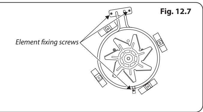
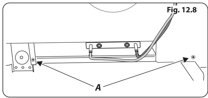

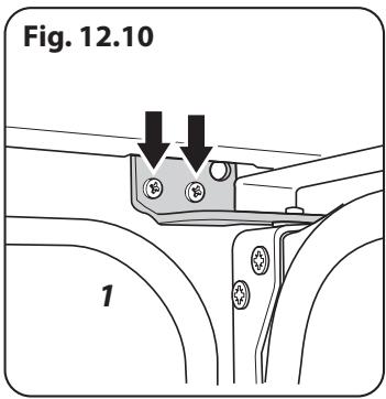
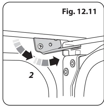

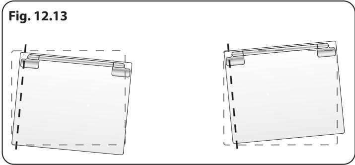
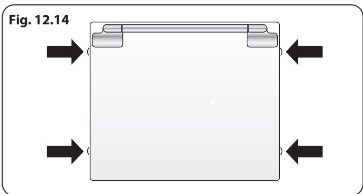
Top Element
Open the left-hand oven door and undo the fixings that secure the heat shield. Remove the top element bracket fixings and withdraw element. Replace the element and re-assemble parts in reverse order.
Check the oven operation.
6 Doors
6.1 To Remove the Grill Door
Remove the left-hand side panel (see 1.2). Remove the plinth (4 screws) and the central vertical cover (5 screws). Remove the 2 countersunk screws (1 each side) securing the grill hinge arms to the front of the grill chamber.
NOTE: The arms are spring tensioned. Carefully remove the grill door. Retain the gaskets.
Reassemble in reverse order, making sure that the gasket is fitted between the hinge arm and the front of the grill chamber.
6.2 To Replace an Oven Door
Open the oven door. Support the door and loosen the 2 screws securing the upper hinge and gasket to the cooker front (Fig. 12.10).
The door is heavy, so take care.
Support the door and remove the screw nearest the hinge pin (Fig. 12.11). Swing the hinge up and away from the door hinge pin. Lift the door away from the lower hinge and remove. Reassemble in reverse order.
6.3 To Adjust an Oven Door Angle
The bottom hinge of either oven door can be adjusted to alter the angle of the door (Fig. 12.12). Loosen the bottom hinge fixing screws and use the notch and a flat bladed screwdriver to move the position of the hinge to set the hinge position (Fig. 12.13).
Retighten the hinge screws.
6.4 To Replace an Oven Door Outer Panel
Move the cooker forwards to gain access to the sides.
Open the oven door slightly and remove the 4 front panel fixing screws from the door sides (2 each side), (Fig. 12.14). Carefully lift off the outer door panel.
Remove the door handle from the panel by unscrewing the 2 retaining nuts. Fit the door handle to the new panel. Fit the panel to the door. Reassemble in the reverse order.
6.5 To Change the Oven Door Latch
Remove the outer door panel (see 6.4). Remove screws 'B', which hold the latch assembly to the inner door panel (Fig. 12.15). Fit the new catch and reassemble in reverse order. Check the door operation.
6.6 To Adjust an Oven Door Catch Keep
Open the oven door, slacken off the locknut at the base of the keep, and screw in or out as required until the required fit is obtained. Retighten the locking nut (Fig. 12.16).
6.7 To Change an Oven Door Seal
Open the oven door. The seal is held in place by small hooks on the rear face. At the corner, pull the seal diagonally away from the door centre until that hook is released (Fig. 12.17). Proceed to the next hook and release it in a similar way, and so on. Use force if the hooks are stiff, as the old seal will be discarded.
When fitting the new seal, position the seal join at the bottom. Hook the new seal in one of the corner holes of the door, and proceed round the door, snapping in each hook in turn.
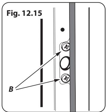
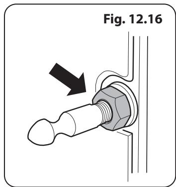
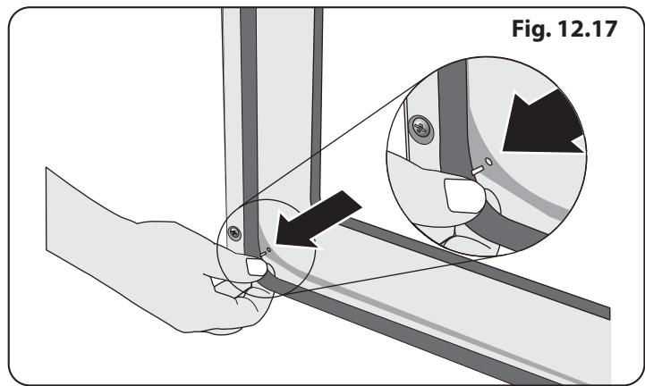
13. Circuit Diagram
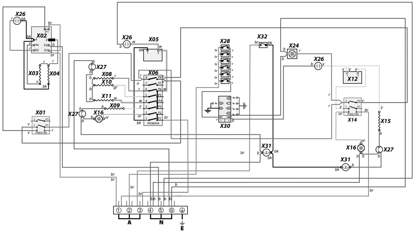
Key
The connections shown in the circuit diagram are for single-phase. The ratings are for 230V50Hz
| Code | Description |
| X01 | Grill Front Switch |
| X02 | Grill Energy Regulator |
| X03 | Left Hand Grill Element |
| X04 | Right Hand Grill Element |
| X05 | Left Hand Oven Thermostat |
| X06 | Left Hand Oven Multifunction Switch |
| X08 | Left Hand Oven Base Element |
| X09 | Left Hand Oven Fan Element |
| X10 | Left Hand Oven Top Outer Element |
| X11 | Left Hand Oven Top Inner Element |
| X12 | Right Hand Oven Thermostat |
| Code | Description |
| X14 | Right Hand Oven Front Switch |
| X15 | Right Hand Oven Fan Element |
| X16 | Oven Fan |
| X24 | Cooling Fan |
| X26 | Neon |
| X27 | Thermal Cut-Out |
| X28 | Ignition Switches |
| X30 | Spark Generator |
| X31 | Oven Light |
| X32 | Oven Light Switch |
| Code | Color |
| b | Blue |
| br | Brown |
| bk | Black |
| or | Orange |
| r | Red |
| v | Violet |
| w | White |
| y | Yellow |
| g/y | Green/yellow |
| gy | Grey |
14. Technical Data
This cooker is designed for use on Natural Gas, although a conversion for LP (LPG X Propane (2.54kPa) ) gas is included.
INSTALLER: Please leave these instructions with the user. DATA BADGE LOCATION: Cooker back, serial number repeater badge below oven door opening. COUNTRY OF DESTINATION: Australia.
Pressures
| Gas (Rp 1/2 at rear right-hand side) | Electric | |
| Supply Pressure at the inlet to appliance regulator | 230/400V 50 Hz | |
| Natural Gas | 1.13 kPa | |
| Propane | 2.75 kPa | |
| Operating Pressure at appliance test point | ||
| Natural Gas | 1 kPa | |
| Propane | 2.54 kPa | |
Dimensions
| Model | Elise 110 Dual Fuel | |
| Overall height | minimum 910 mm | maximum 935 mm |
| Overall width | 1092 mm | |
| Overall depth | 598 mm excluding handles, 650 mm including handles | |
| Minimum height above the hotplate | 650 mm | |
Hotplate Ratings
| BSI Evo 1 Type Burners Australia | |||||||
| Burner Type | Bypass Screw* | Natural Gas 1.0 kPa | Propane 2.54 kPa | ||||
| Input | Injector | Input | Injector | ||||
| Marking | Size Ø | Marking | Size Ø | ||||
| Wok | 75 | 15.2 MJ/h-1 | 198 | 1.93 mm | 15.0 MJ/h-1 | 111 | 1.07 mm |
| Rapide / Large | 41 | 12.3 MJ/h-1 | 165 | 1.65 mm | 12.0 MJ/h-1 | 89 | 0.96 mm |
| Semi Rapide / Medium | 33 | 6.2 MJ/h-1 | 115 | 1.15 mm | 6.2 MJ/h-1 | 67 | 0.68 mm |
| Auxillary / Small | 25 | 3.7 MJ/h-1 | 92 | 0.92 mm | 3.3 MJ/h-1 | 45 | 0.50 mm |
- The valves in this cooker are fitted with adjustable bypass screws. The cooker is supplied with the bypass screws set for Natural Gas. For LPG conversion the bypass screws must be screwed all the way down.
Oven Efficiencies
| Ovens | Left-hand Oven | Right-hand Oven | |
| Multifunction | Forced Air Convection | ||
| Maximum power output @ 230 V 50 Hz | 2.5 kW | 2.5 kW | |
| Energy efficiency class on a scale of A (more efficient) to G (less efficient) | A | A | |
| Energy consumption based on standard load | 0.88 kWh | 0.88 kWh | |
| Usable volume (litres) | 79 | 79 | |
| Size | Large | Large | |
| Time to cook standard load | 41 minutes | 41 minutes | |
| Surface area of the grid | 1400 cm² | 1400 cm² | |
| Grill | 2.3 kW | ||
Maximum total electrical load at 230V (approximate total including oven lights, oven fan, etc.): 7.4 kW.
Clarence Street, Royal Leamington Spa,
Warwickshire, CV31 2AD, England.
www.falconworld.com

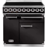

- Cooker Overview 7
- Using the Glide-out Grill™ 14
- Cooking tips 15
- Cooking Table 16
- Cleaning your cooker 17
- Troubleshooting 21
- Service and Spares 24
- Installation 25
- Final Fitting 33
- Conversion to LP Gas 34
- Servicing 36
- Circuit Diagram 43
- Technical Data 44
- Before You Start…
- Personal Safety
- Electrical Connection Safety
- WARNING: THE APPLIANCE MUST BE EARTHED.
- Gas Connection Safety
- If You Smell Gas
- Peculiar Smells
- Cooling Fan
- Ventilation
- Maintenance
- Oven Care
- Oven Shelves (dependant on model)
- Grill/Glide-out Grill™ Care
- Cooker Care
- Cleaning
- Range Overview
- Hotplate Burners
- Wok Burner
- The Wok Cradle
- The Griddle Plate (optional)
- The Glide-out Grill™ (Fig. 2.15)
- The Ovens
- The Multi-function Oven
- Multi-function Oven Functions
- Defrost
- Fan Oven
- Fanned Grilling
- Fan Assisted Oven
- Conventional Oven (Top and Base Heat)
- Browning Element
- Base Heat
- The Fan Oven
- Operating the Ovens
- Operating the Multi-function Oven
- Operating the Fan Oven
- Main Oven Light
- Accessories
- Oven Shelves
- Telescopic runners - Left-hand (Main) Oven
- To remove the glide-out shelf
- To remove the glide-out runners
- To refit the glide-out runners
- Storage
- Using the Glide-out Grill™
- Cooking tips
- Cooking with a multifunction oven
- General oven tips
- When the oven is on, do not leave the door open for longer than necessary, otherwise the knobs may get very hot.
- Cooking Table
- Cleaning your cooker
- Essential information
- The Single Ring Burners
- The Wok Burner
- The Griddle (optional)
- Glide-out Grill
- Cleaning the Glide-out Grill
- DO NOT put the side runners in a dishwasher.
- Control panel and doors
- Glass fronted door panels
- Ovens
- 'Cook & Clean' Panels
- Removing the main oven linings
- Cleaning table
- Troubleshooting
- Hotplate/Cooktop ignition or hotplate burners faulty
- Hotplate/Cooktop burners will not light
- Steam is coming from the oven
- What cleaning materials are recommended for the cooker?
- Never use caustic or abrasive cleaners as these will damage the surface.
- An oven fan is noisy
- If there is an installation problem and I don't get my original installer to come back to fix it who pays?
- Poor performance
- Food is cooking too slowly, too quickly, or burning
- The oven is not cooking evenly.
- Oven not coming on
- Oven temperature getting hotter as the cooker gets older
- Oven light is not working
- The oven door is misaligned
- Grill
- The fascia gets hot when I use the oven or grill
- The knobs get hot when I use the oven or the grill. Can I avoid this?
- Grill is not cooking properly
- INSTALLATION
- Service and Spares
- If You Have a Problem
- Please Note
- Out of Warranty
- Spare Parts
- Installation
- Location of cooker
- Conversion
- Positioning the Range
- Overhead - Measurement A
- Side Clearances - Measurements B & C
- Side Clearances - Measurement D & E
- When Fitting Between Kitchen Cabinets
- Moving the cooker
- Lowering the two rear rollers
- Completing the move
- Levelling
- Fitting a Stability Bracket
- Fitting the Restraining Chain
- Repositioning the cooker following connection
- Gas Connection
- Natural Gas
- Propane
- Pressure Testing
- See the data badge for test pressures.
- Electrical Connection
- WARNING: THIS APPLIANCE MUST BE EARTHED.
- Current Operated Earth Leakage Breakers
- Connection in New Zealand
- OR
- Fixed Wiring
- Disconnect from the mains supply.
- Final Fitting
- Fitting the Handrail
- NOTE: The handle support should face upwards.
- Fitting the Pan Supports
- Fitting the Plinth
- Final Checks
- Hob Check
- Grill Check
- Oven Check
- Customer Care
- Conversion to LP Gas
- Conversion from Natural Gas
- (1.0 kPa) to LPG X Propane
- (2.54 kPa)
- Hotplate
- Injectors
- Bypass Screw Adjustment
- Removing the Control Panel
- Set the Governor
- Affix Label
- Servicing
- Panels
- To Remove the Control Panel
- To Remove the Side Panels
- Hotplate
- To remove the hotplate
- To Replace the Hotplate Control Taps
- To Change a Hotplate Burner Injector
- To Replace a Hotplate Burner Electrode
- To Replace a Hotplate Burner
- DISCONNECT FROM THE ELECTRICITY SUPPLY.
- To Change a Hotplate Burner Thermocouple
- Controls
- To Replace the Ignition or Light Switch
- Grill
- To Replace the Grill Controller
- To Replace the Grill Element
- Ovens
- To Replace an Oven Thermostat
- To Remove an Oven Inner Back
- To Change the Fan in the Right-hand Oven
- To Remove an Oven Element Thermal Cut-out
- To Remove the Right-hand Oven Element
- To Remove the Left-hand Oven Bottom and Top Elements
- Bottom Element
- Top Element
- Doors
- To Remove the Grill Door
- To Replace an Oven Door
- The door is heavy, so take care.
- To Adjust an Oven Door Angle
- To Replace an Oven Door Outer Panel
- To Change the Oven Door Latch
- To Adjust an Oven Door Catch Keep
- To Change an Oven Door Seal
- Circuit Diagram
- Key
- Technical Data
Brand : FALCON
Model : ELISE 110 ELS110DFCA
Category : Cooker