
FHX-700BT - Car stereo PIONEER - Free user manual and instructions
Find the device manual for free FHX-700BT PIONEER in PDF.
Download the instructions for your Car stereo in PDF format for free! Find your manual FHX-700BT - PIONEER and take your electronic device back in hand. On this page are published all the documents necessary for the use of your device. FHX-700BT by PIONEER.
USER MANUAL FHX-700BT PIONEER
Important ! Check all connections and systems before final installation. ! Do not use unauthorized parts as this may cause malfunctions. ! Consult your dealer if installation requires drilling of holes or other modifications to the vehicle. ! Do not install this unit where: — it may interfere with operation of the vehicle. — it may cause injury to a passenger as a result of a sudden stop. How to install
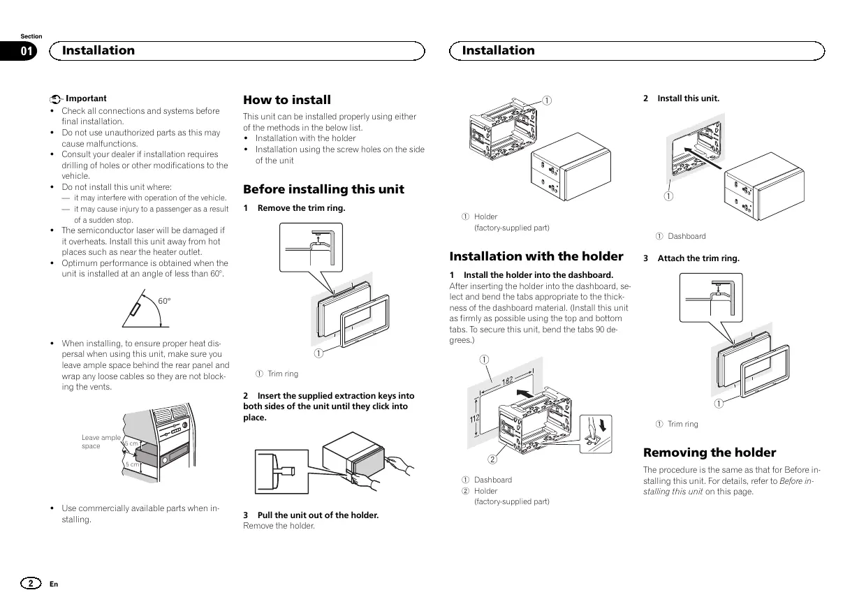
1 Holder (factory-supplied part) 1 Dashboard Installation with the holder
Attach the trim ring.
1 Trim ring Leave ample 5 cm space
1 Install the holder into the dashboard. After inserting the holder into the dashboard, select and bend the tabs appropriate to the thickness of the dashboard material. (Install this unit as firmly as possible using the top and bottom tabs. To secure this unit, bend the tabs 90 degrees.) 2 Insert the supplied extraction keys into both sides of the unit until they click into place.
! Use commercially available parts when installing. Remove the trim ring. 60° 5 cm
Before installing this unit ! The semiconductor laser will be damaged if it overheats. Install this unit away from hot places such as near the heater outlet. ! Optimum performance is obtained when the unit is installed at an angle of less than 60°. ! When installing, to ensure proper heat dispersal when using this unit, make sure you leave ample space behind the rear panel and wrap any loose cables so they are not blocking the vents.
This unit can be installed properly using either of the methods in the below list. ! Installation with the holder ! Installation using the screw holes on the side of the unit 1 Dashboard 2 Holder (factory-supplied part) 3 Pull the unit out of the holder. Remove the holder. Removing the holder The procedure is the same as that for Before installing this unit. For details, refer to Before installing this unit on this page. Section Installation
% Fastening the unit to the factory radiomounting bracket. Position the unit so that its screw holes are aligned with the screw holes of the bracket, and tighten the screws at 3 locations on each side. Important ! When installing this unit in a vehicle without an ACC (accessory) position on the ignition switch, failure to connect the red cable to the terminal that detects operation of the ignition key may result in battery drain. STAR
ACC position No ACC position ! Use of this unit in conditions other than the following could result in fire or malfunction. — Vehicles with a 12-volt battery and negative grounding. — Speakers with 50 W (output value) and 4 W to 8 W (impedance value).
If the pawl gets in the way, bend it down. Factory radio mounting bracket Truss (5 mm × 8 mm) screws Dashboard or console ! To prevent a short-circuit, overheating or malfunction, be sure to follow the directions below. — Disconnect the negative terminal of the battery before installation. — Secure the wiring with cable clamps or adhesive tape. Wrap adhesive tape around wiring that comes into contact with metal parts to protect the wiring. — Place all cables away from moving parts, such as the shift lever and seat rails. — Place all cables away from hot places, such as near the heater outlet. — Do not connect the yellow cable to the battery by passing it through the hole to the engine compartment. — Cover any disconnected cable connectors with insulating tape. — Do not shorten any cables. — Never cut the insulation of the power cable of this unit in order to share the power with other devices. The current capacity of the cable is limited. — Use a fuse of the rating prescribed. — Never wire the negative speaker cable directly to ground. — Never band together negative cables of multiple speakers. English Installation using the screw holes on the side of the unit ! When this unit is on, control signals are sent through the blue/white cable. Connect this cable to the system remote control of an external power amp or the vehicle’s auto-antenna relay control terminal (max. 300 mA 12 V DC). If the vehicle is equipped with a glass antenna, connect it to the antenna booster power supply terminal. ! Never connect the blue/white cable to the power terminal of an external power amp. Also, never connect it to the power terminal of the auto antenna. Doing so may result in battery drain or a malfunction. ! The black cable is ground. Ground cables for this unit and other equipment (especially, high-current products such as power amps) must be wired separately. If they are not, an accidental detachment may result in a fire or malfunction. This unit
6 Antenna input 7 Fuse (10 A) 8 Wired remote input Hard-wired remote control adapter can be connected (sold separately). Power cord
1 To power cord input 2 Depending on the kind of vehicle, the function of 3 and 5 may be different. In this case, be sure to connect 4 to 5 and 6 to 3 Yellow Back-up (or accessory) 4 Yellow Connect to the constant 12 V supply terminal. 5 Red Accessory (or back-up) 6 Red Connect to terminal controlled by ignition switch (12 V DC).
7 Connect leads of the same color to each other. 8 Black (chassis ground) 9 Blue/white The pin position of the ISO connector will differ depending on the type of vehicle. Connect 9 and b when Pin 5 is an antenna control type. In another type of vehicle, never connect 9 and b. a Blue/white Connect to system control terminal of the power amp (max. 300 mA 12 V DC). b Blue/white Connect to auto-antenna relay control terminal (max. 300 mA 12 V DC). c Speaker leads White: Front left + White/black: Front left * Gray: Front right + Gray/black: Front right * Green: Rear left + or subwoofer + Green/black: Rear left * or subwoofer * Violet: Rear right + or subwoofer + Violet/black: Rear right * or subwoofer * d ISO connector In some vehicles, the ISO connector may be divided into two. In this case, be sure to connect to both connectors. Notes ! Change the initial setting of this unit (refer to the operation manual). The subwoofer output of this unit is monaural. ! When using a subwoofer of 70 W (2 W), be sure to connect the subwoofer to the violet and violet/black leads of this unit. Do not connect anything to the green and green/ black leads. Power amp (sold separately) Perform these connections when using the optional amplifier.
1 System remote control Connect to Blue/white cable. 2 Power amp (sold separately) 3 Connect with RCA cables (sold separately) 4 To Front output 5 Front speaker 6 To Rear output or subwoofer output 7 Rear speaker or subwoofer Section Installing the microphone
Installing the microphone English 2 Install the microphone clip on the steering column.
CAUTION It is extremely dangerous to allow the microphone lead to become wound around the steering column or shift lever. Be sure to install the unit in such a way that it will not obstruct driving.
Note Install the microphone in a position and orientation that will enable it to pick up the voice of the person operating the system.
When installing the microphone on the sun visor 1 Install the microphone on the microphone clip.
1 Microphone clip 2 Clamp Use separately sold clamps to secure the lead where necessary inside the vehicle. When installing the microphone on the steering column 1 Install the microphone on the microphone clip. 1 Microphone 2 Microphone clip 2 Install the microphone clip on the sun visor. With the sun visor up, install the microphone clip. (Lowering the sun visor reduces the voice recognition rate.)
1 Microphone 2 Microphone base 3 Microphone clip 4 Fit the microphone lead into the groove. # Microphone can be installed without using microphone clip. In this case, detach the microphone base from the microphone clip. To detach the microphone base from the microphone clip, slide the microphone base.
1 Double-sided tape 2 Install the microphone clip on the rear side of the steering column. 3 Clamp Use separately sold clamps to secure the lead where necessary inside the vehicle. Adjusting the microphone angle The microphone angle can be adjusted.
Installation Installation Sans position ACC 1 Microphone 2 Clip microphone PIONEER CORPORATION 1-1, Shin-ogura, Saiwai-ku, Kawasaki-shi, Kanagawa 212-0031, JAPAN Корпорация Пайонир