DIN Dimmer - Light dimmer Qubino - Free user manual and instructions
Find the device manual for free DIN Dimmer Qubino in PDF.


| Product type | DIN rail lighting dimmer |
| Brand | Qubino |
| Model | DIN Dimmer PLUS extended 2.3 2 |
| Supply voltage | 110-240 VAC, 24 VDC |
| Load type | Low-voltage halogen, dimmable compact fluorescent, dimmable LED |
| Switching | MOSFET |
| Remote dimming | Yes, via smartphone |
| Consumption measurement | Yes, power and kWh |
| Temperature sensor | Compatible, sold separately |
| Local control | Push-button / toggle switch |
| Installation | DIN rail, electrical box |
| Protocol | Z-Wave (repeater) |
| Network range | Improved thanks to repeater function |
| Dimensions | 36 mm (2 DIN modules) |
| Weight | Approximately 100 g |
| Protection rating | IP20 |
| Operating temperature | 0 °C to 40 °C |
| Maintenance | No special maintenance, clean with a dry cloth |
| Safety | Installation by a qualified electrician, cut off the power supply |
| Repairability | Not user-repairable, contact support |
| General information | Compatible with Z-Wave gateways, updates via Z-Wave |
Frequently Asked Questions - DIN Dimmer Qubino
User questions about DIN Dimmer Qubino
0 question about this device. Answer the ones you know or ask your own.
Ask a new question about this device
Download the instructions for your Light dimmer in PDF format for free! Find your manual DIN Dimmer - Qubino and take your electronic device back in hand. On this page are published all the documents necessary for the use of your device. DIN Dimmer by Qubino.
USER MANUAL DIN Dimmer Qubino
qubino®
Your little magic for the smartest home.
USER MANUAL
DIN Dimmer


Remotely dim your lights via smart phone.
Table of contents
Where To Buy....4
- Introduction ...... 4
- Use Cases .... 5
2.1. Installation examples where DIN Dimmer is installed on the DIN rail 6
2.2. Installation examples where DIN Dimmer is installed in combination with temperature sensor....7
2.3. Additional features of DIN Dimmer which can make your life easier .... 8
- Qubino DIN Dimmer Advantages and Highlights.... 10
3.1. Advantages.... 10
3.2. Highlights 14
- Installation 15
4.1. Installing the device on the DIN rail.... 17
4.2. Installing the Qubino Temperature Sensor 23
- Device Information and Support.... 29
- Electrical Diagram (110 - 240VAC, 24VDC) 31
- Adding the device to a Z-Wave network (Inclusion).... 32
- Removing the device from a Z-Wave network (Exclusion).... 33
- Associations 34
- Technical Terms for Switches 36
- Configuration Parameters.... 37
- Compatibility with Z-Wave Gateways (hubs) 46
- Technical Specifications 47
- Package Contents.... 49
- Z-Wave Command Classes 50
- About Qubino....53
EN
- Safety Information 55
- DIN Dimmer - Available Frequencies 56
- Important Disclaimer 57
- Warning....57
- Regulations....57
Where To Buy
To find your nearest Qubino dealer visit: http://qubino.com/where-to-buy/
1. Introduction
DIN Dimmer is a MOSFET-switching light device that also supports control of low-voltage halogen lamps with electronic transformers, dimmable compact fluorescent lights, and dimmable LED bulbs. It measures power consumption of the connected device, and can be paired with a digital temperature sensor (sold separately). It supports push-button/momentary switches (default). and toggle switches Qubino DIN Dimmer allows the easiest and quickest installation on the DIN rail (in the electric box).

The connection of a digital temperature sensor means you can create complex scenes and control any device relative to a set temperature range. The Qubino DIN Dimmer also acts as a Z-Wave repeater to improve the range and stability of the Z-Wave network.
2. Use Cases
The DIN Dimmer can be used in many different scenes, which can help make your life more comfortable. We have prepared a few of them for you-so you can get an idea for your next smart home project. Of course, there are countless of other options for how to use Qubino DIN Dimmer to remotely control devices via your smartphone.
There are different switch types in different countries, as for example:
EU example:

USA example:
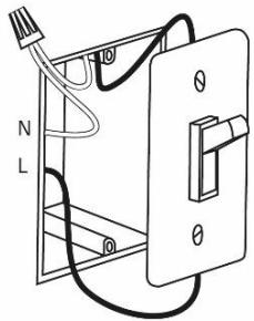
ITA/Brasil example:

UK example:

Further in the document you will notice that all the use cases show the USA example switch type. Note that the product works in the same way with EU switch type, ITA/Brazil type, UK type etc.
For more information on how to install your device, please refer to the Installation chapter.
2.1. Installation examples where DIN Dimmer is installed on the DIN rail
- Remotely dim the lights or turn them ON/OFF

2.2. Installation examples where DIN Dimmer is installed in combination with temperature sensor
- Remotely measure room temperature (*The temperature sensor is sold separately - for more info, please see Qubino catalogue. Product ordering code (model number): ZMNHEA1)

2.3. Additional features of DIN Dimmer which can make your life easier
- Do you often forget to turn off devices when you leave your home, like lights in the basement or attic?
- The DIN Dimmer can automatically turn lights on or off after a set period of time (when you're away from home). For example, the light will automatically turn off if it's been on for 8 hours, let's say. This function is independent of other scenes and gateway (hub) commands.

- Do you know how much energy you consume?
- The DIN Dimmer monitors and reports energy consumption of connected devices in real time to your smart home app (your gateway (hub) needs to support this feature). Know how much power your lights are using.

- Want to control other devices in your Z-Wave network with the DIN Dimmer?
- Connect the DIN Dimmer with other devices in your network to remotely and automatically trigger another Z-Wave device. And have other Z-Wave devices trigger your Qubino DIN Dimmer.

3. Qubino DIN Dimmer Advantages and Highlights
3.1. Advantages
- Qubino DIN Dimmer allows the easiest and quickest installation. There is no simpler installation than DIN rail installation – and the Qubino DIN Dimmer is a DIN rail mounted device so the installation is really simple.

- The Qubino DIN Dimmer has the option to connect a temperature sensor*, through which users can monitor the ambient air or water temperature. It's the only Z-Wave DIN rail mounted dimmer in the world which offers this option. With a connected sensor, the user can monitor accurate measurements of the room temperature, pool water temperature, etc. Qubino DIN Dimmer, along with the temperature sensor, is connected directly to the power supply. Install it and forget it – no need to worry about dying batteries, like with battery-powered sensors.
*The temperature sensor is sold separately - for more info, please see Qubino catalogue. Product ordering code (model number): ZMNHEA1

i Please do not put the temperature sensor directly into the water! The temperature sensor is designed to measure the water temperature by being mounted to the water pipe.
- Qubino guarantees 100% device quality. Such high quality can be delivered because every Qubino goes through rigorous quality control standards throughout the production process. Every device has a unique serial number and a part number, which are assigned to the device only after it goes through a strict testing procedure.

- By scanning the QR code on the side of your Qubino device, the serial and part numbers will be automatically copied on your mobile phone; they also provide direct access to Qubino's technical support team. The serial and part numbers of your device are given automatically every time you open an inquiry with our support team: this instantly shares the relevant device information we need to provide the best technical support possible. For details, please see the Device Information and Support chapter.

- The Qubino DIN Dimmer is engineered and manufactured in the EU, and contains only the highest quality components.

- The Qubino DIN Dimmer is certified by an independent European Institute and has CE, FCC, LVD and EMC certificates to ensure the highest safety standards.

- The Qubino DIN Dimmer allows a direct connection of even the smallest bulbs. It’s the only Z-Wave dimmer on the market that does not require any minimum load power, which means that the user can connect the bulbs with minimum power loads that are bigger than 0 W. So there is no need for buying a bypass for connecting for example LED lights with 3 W, 7 W, 10 W etc.


3.2. Highlights
- Remote (via smartphone or PC) and local on/off control of ALL dimmable bulbs
- Works with push-button (momentary switch) or toggle switches
- Capable of measuring the power consumption of the connected device in real time via smartphone, which allows you to save on electricity bills*
- Features one of the easiest and quickest installations of devices of this kind; it's mounted on the DIN rail
- Saves and restores the last status after a power failure.
• Supports auto-inclusion mode for quick set up - Can automatically turn devices on and off after a set period of time (helpful when you're away from home, for example)*
- Supports additional parameters for expert users, which allows for advanced configuration*
- Acts as a signal repeater which improves the range and stability of your Z-Wave network
- Can be used to remotely control and trigger other devices in your Z-Wave network
*Your gateway (hub) needs to support advanced configuration and parameter input if you wish to use this feature
4. Installation
WHAT YOU NEED FOR THE INSTALLATION:

Before installing the device, please read the following carefully and follow the instructions exactly:

i Danger of electrocution!
Installation of this device requires a great degree of skill and may be performed only by a licensed and qualified electrician. Please keep in mind that even when the device is turned off, voltage may still be present in the device's terminals.
i Note!
Do not connect the device to loads exceeding the recommended values. Connect the device exactly as shown in the provided diagrams. Improper wiring may be dangerous and result in equipment damage.
i Note!
The installation manual is valid only for DIN Dimmer version P3 and above!
4.1. Installing the device on the DIN rail
The installation process, tested and approved by professional electricians, consists of the following simple steps:
Step 1 – Turn OFF the fuse:
- To prevent electrical shock and/or equipment damage, disconnect electrical power at the main fuse or circuit breaker before installation and maintenance.
- Be aware that even if the circuit breaker is off, some voltage may remain in the wires — before proceeding with the installation, be sure no voltage is present in the wiring.
• Take extra precautions to avoid accidentally turning the device on during installation.
STEP 1

Step 2 – Installing the device:
- Connect the device exactly according to the diagrams shown below
STEP 2
Before Qubino installation:

After Qubino installation:

i Note!
- Place the antenna as far as possible from metal elements as they may cause signal interference.
- Do not shorten the antenna.
The device's antenna should be as upright as possible. This ensures the device's operational range is maximized (up to 98 feet (30 m) line of sight).

Step 3 – Turn ON the fuse:

Step 4 – Add the device to your Z-Wave network:
- For more details on how to include the device, please refer to the Z-Wave Inclusion chapter.

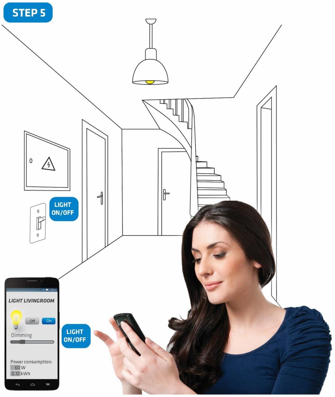
Step 5 – The Installation is now complete. It’s time to make your life more comfortable with the help of the Qubino DIN Dimmer
4.2. Installing the Qubino Temperature Sensor
The temperature sensor is a Qubino accessory and is sold separately - for more info, please see the Qubino product catalogue or website: http://qubino.com/products/accessories/
Product ordering code: ZMNHEA1
Qubino Z-Wave devices have the option to connect a temperature sensor (sold separately), which allows you to remotely monitor ambient or water temperature. Qubino devices are the only Z-Wave devices of its kind to offer this unique capability. With the sensor connected to the device, you can carry out accurate measurements of room temperature, pool water temperature, etc. and build automation rules around them. Qubino device with a temperature sensor is connected directly to power supply. Install it and forget it, there is no need to worry about changing the batteries like with most other Z-Wave temperature sensors which run on batteries. The temperature sensor's range is between -50 and 125°C (-58 and 257°F).

The digital Temperature sensor comes with a 1 m (3.3 ft) cord and a connector to attach it directly to a Qubino device.
- To prevent electrical shock, make sure that no voltage is present on the temperature sensor cable.
- When connected to Qubino device, the temperature sensor is under high voltage, which is very dangerous.
- Goap d.o.o. does not take responsibility for any damage or electrical shock due to incorrect sensor assembly.
- The above instructions and description apply to a temperature sensor compatible with Qubino products only.
Temperature sensor installation example:
Step 1 – Exclude the device (if it is already connected to your Z-Wave system)

Step 2 – Switch OFF the power supply
STEP 2

Step 3 – Connect the temperature sensor as shown below
STEP 3

Step 4: Place the temperature sensor in the switch box


Step 5 – Turn the fuse ON

Step 6 – Re-include the device to your network

Step 7 – Start using the temperature sensor in connection with your device

5. Device Information and Support
DIN Dimmer supported functions:
| Dim the Lights | Turn on/off | kWh Measurement | W Measurement | Temperature Sensor | Associations | Z-Wave Repeater | Auto-inclusion | Automatically turn ON/OFF |
| √ | √ | √ | √ | √ | √ | √ | √ | √ |
Did you know that Qubino offers Z-Wave devices with 100% quality control guaranteed throughout the production process? Every single unit is tested and examined before being approved for sale – a truly unique pledge in the industry.
Why is this important?
Every device has a dedicated serial number and part number, which is assigned to the device only after it goes through a strict testing procedure.
By scanning the QR code on the back of your Qubino, its device title, serial number, and part number are automatically copied to your mobile phone. You can also use the code for direct access to the device page for more information. If you still don't find what you're looking for, click on the link to Qubino technical support team. They will be able to automatically read the serial and part number from your device and quickly review the production log file containing the production date as well as any relevant device parameters and information. This process allows our team to immediately identify and address issues, giving you the best support possible.
GET SUPPORT IN 3 SIMPLE STEPS:

Based on customer and business partner feedback, we're proud to boast Qubino's support team as the best and fastest on the market. If you don't find the answers to your questions in this document, please contact our support team by scanning the QR code on your device or through our website: http://qubino.com/support/#email. We will try to help you as soon as possible.
6. Electrical Diagram (110 - 240VAC, 24VDC)

Notes for diagram:
| N | Neutral wire (+VDC) |
| L | Live (line) wire (-VDC) |
| Q | Output for electrical device |
| I | Input for switch/push button |
| LED | Red – overload; Green – Power ON (solid) / no ID (blinking slow 1s) |
| TS | Terminal for digital temperature sensor (only for DIN Dimmer device compatible digital temperature sensor, which must be ordered separately) |
| S | Service button (used to add or remove the device from the Z-Wave network) |
NOTE: When overload is detected, the device automatically switches off. If this happens, check if the load matches device specifications and if connections are according to the diagram. To restore the dimmer to regular operation, please power cycle the device.
7. Adding the device to a Z-Wave network (Inclusion)
AUTOMATICALLY ADDING THE DEVICE TO A Z-WAVE NETWORK (AUTO INCLUSION)
- Enable add/remove mode on your Z-Wave gateway (hub)
- Connect the device to the power supply (with the temperature sensor already connected – sold separately*).
- Auto-inclusion will be initiated within 5 seconds of connection to the power supply and the device will automatically enrol in your network
MANUALLY ADDING THE DEVICE TO A Z-WAVE NETWORK (MANUAL INCLUSION)
- Enable add/remove mode on your Z-Wave gateway (hub)
- Connect the device to the power supply (with the temperature sensor already connected*)
- Toggle the switch connected to the I1 terminal 3 times within 3 seconds
OR
Press and hold the S (Service) button for at least 2 seconds
- A new multi-channel device will appear on your dashboard
*If connecting the temperature sensor, switch off the power supply and make sure the device is excluded from your network BEFORE connecting the sensor.
① Make sure the device is excluded from your network before connecting the temperature sensor. Switch off the power supply, connect the temperature sensor, and re-include the device to your network.
8. Removing the device from a Z-Wave network (Exclusion)
REMOVAL FROM A ZWAVE NETWORK (Z-WAVE EXCLUSION)
- Connect the device to the power supply
- Make sure the device is within direct range of your Z-Wave gateway (hub) or use a handheld Z-Wave remote to perform exclusion
- Enable add/remove mode on your Z-Wave gateway (hub)
- Toggle the switch connected to the I1 terminal 3 times within 3 seconds
OR
Press and hold the S (Service) button between 2 and 6 seconds
- The device will be removed from your network but any custom configuration parameters will not be erased
FACTORY RESET
- Connect the device to the power supply
- Within the first minute the device is connected to the power supply, toggle the switch connected to the I1 terminal 5 times within 3 seconds
OR
Press and hold the S (Service) button for at least 6 seconds
① By resetting the device, all custom parameters previously set on the device will return to their default values, and the owner ID will be deleted. Use this reset procedure only when the main gateway (hub) is missing or otherwise inoperable.
9. Associations
Use associations for direct communication between the DIN Dimmer and other devices within your Z-Wave network without the need of your primary gateway (hub).
Association Groups:
Root device:
- Group 1: Lifeline group (reserved for communication with the primary gateway (hub)), 1 node allowed.
- Group 2: Basic on/off (status change report for output), up to 16 nodes.
- Group 3: Start level change/stop (status change report for I1 input), up to 16 nodes.*
- Group 4: Multilevel set (status change report of the output) up to 16 nodes*
- Group 5: Multilevel sensor report (external temperature sensor report – sensor sold separately), up to 16 nodes.
*Note: If the device is in switch mode (Parameter No. 5) the association Group 3 and 4 has no effect.
Endpoint 1:
• Group 1: Lifeline group, 0 nodes allowed.
- Group 2: basic on/off (triggered at change of the input I1 state and reflecting the output) up to 16 nodes
- Group 3: start level change/stop level change (triggered at change of the input I1 state and reflecting its state) up to 16 nodes*
- Group 4: multilevel set (triggered at changes of state/value of the output) up to 16 nodes*
**Note: If the device is in switch mode (Parameter No. 5) the association Group 3 and 4 has no effect.
•
Endpoint 2:
• Group 1: Lifeline group, 0 nodes allowed.
- Group 2: multilevel sensor report (triggered at change of temperature sensor) up to 16 nodes.
10. Technical Terms for Switches
| Symbol | Switch example images | Definition | EU | USA | Qubino | Other names | ||
 |  |  from behind from behind | Single pole, single throw (SPST) - One switch controlling one light / circuit of lights | One-way switch | Two-way switch (regular switch) | Toggle switch | Switch; Bi-stable switch | |
 |  |  from behind from behind | Single pole, double throw (SPDT) - Two switches controlling the same light / circuit of lights | Two-way switch | Three-way switch | Two-way switch | ||
 |  |  from behind from behind | Used when you have three or more switches controlling the same light | Intermediate switch | Four-way switch | Intermediate switch | Crossover switch; Cross connection | |
 |  |  from behind from behind | After being released, it goes back to its original state | Momentary switch | Momentary switch | Monostable switch; Push button | ||
11. Configuration Parameters
Parameter no. 1 – In-wall Switch Type for Load 1 (Q) to control I1
With this parameter, you can select between push-button (momentary) and on/off toggle switch types.
Values (size is 1 byte dec):
- default value 0
• 0 - push-button (momentary)
• 1 - on/off toggle switch

MOMENTARY SWITCH


TOGGLE SWITCH

Parameter no. 5 – Working mode
With this parameter, you can change the device presentation on the user interface.
Values (size is 1 byte dec):
- default value 0
- 0 - Dimmer mode
• 1 - Switch mode
NOTE: After parameter change, first exclude device (without setting parameters to default value) then wait at least 30s and then re include the device!


Parameter no. 10 - Activate / deactivate ALL ON / ALL OFF Functionality
DIN Dimmer device responds to commands ALL ON / ALL OFF that may be sent by the primary or secondary gateway (hub) within the Z-Wave network.
Values (size is 2 byte dec):
- default value 255
• 255 - ALL ON active, ALL OFF active
• 0 - ALL ON not active, ALL OFF not active
• 1 - ALL ON not active, ALL OFF active
• 2 - ALL ON active, ALL OFF not active

ON

OFF
Parameter no. 11 - Turn Load 1 (Q) OFF Automatically with Timer
If Load 1 (Q) is ON, you can schedule it to turn OFF automatically after a period of time defined in this parameter. The timer is reset to zero each time the device receives an ON command, either remotely (from the gateway (hub) or associated device) or locally from the switch.
Values (size is 2 byte dec):
- default value 0
• 0 - Auto OFF Disabled - 1 - 32536 = 1 - 32536 seconds - Auto OFF timer enabled for a given amount of seconds

Parameter no. 12 - Turn Load 1 (Q) ON Automatically with Timer
If Load (Q) is OFF, you can schedule it to turn ON automatically after a period of time defined in this parameter. The timer is reset to zero each time the device receives an OFF command, either remotely (from the gateway (hub) or associated device) or locally from the switch.
Values (size is 2 byte dec):
- default value 0
• 0 - Auto ON Disabled - 1 - 32536 = 1 - 32536 seconds .Auto ON timer enabled- for a given amount of seconds

Parameter no. 21 - Enable/Disable the Double click function
If the Double click function is enabled, a fast double click on the push-button will set the dimming level to the maximum dimming value.
Values (size is 1 byte dec):
- default value 0
• 0 - double click disabled
• 1 - double click enabled

Parameter no. 30 - Restore on/off status for Q load after power failure
This parameter determines if on/off status is saved and restored for the load Q after power failure.
Values (size is 1 byte dec):
- default value 0
- 0 - Device saves last on/off status and restores it after a power failure.
- 1 - Device does not save on/off status and does not restore it after a power failure, it remains off.

Parameter no. 40 – Watt Power Consumption Reporting Threshold for Q Load
Choose by how much power consumption needs to increase or decrease to be reported. Values correspond to percentages so if 10 is set, the device will report any power consumption changes of 10% or more compared to the last reading.
Values (size is 1 byte dec):
- default value 5
• 0 - Power consumption reporting disabled - 1 - 100 = 1% - 100% Power consumption reporting enabled. New value is reported only when Wattage in real time changes by more than the percentage value set in this parameter compared to the previous Wattage reading, starting at 1% (the lowest value possible).
NOTE: Power consumption needs to increase or decrease by at least 1 Watt to be reported, REGARDLESS of percentage set in this parameter.

Parameter no. 42 – Watt Power Consumption Reporting Time Threshold for Q Load
Set value refers to the time interval with which power consumption in Watts is reported (0 – 32767 seconds). If 300 is entered, energy consumption reports will be sent to the gateway (hub) every 300 seconds (or 5 minutes).
Values (size is 2 byte dec):
- default value 0
• 0 - 29 Power consumption reporting disabled - 30 - 32767 = 30 seconds to 32767 seconds. Power consumption reporting enabled. Report is sent according to time interval (value) set here.

Parameter no. 60 - Minimum dimming value
The value set in this parameter determines the minimum dimming value (the lowest value which can be set on the device, when, for example, dimming lights with wall switch or slider in the GUI (Gateway - hub))
Values (size is 1 byte dec):
• default value 1 = 1% (minimum dimming value)
- 1-98 = 1% - 98%, step is 1%. Minimum dimming value is set by entering a value.
NOTE: The minimum level may not be higher than the maximum level! 1% min. dimming value is defined by the Z-Wave multilevel device class.

Parameter no. 61 - Maximum dimming value
The value set in this parameter determines the maximum dimming value (the highest value which can be set on the device, when, for example, dimming lights with wall switch or slider in the GUI (Gateway - hub)) Values (size is 1 byte dec):
• default value 99 = 99% (Maximum dimming value)
- 2-99 = 2% - 99%, step is 1%. Maximum dimming value is set by entering a value.
NOTE: The maximum level may not be lower than the minimum level! 99% max. dimming value is defined by the Z-Wave multilevel device class.

Parameter no. 65 - Dimming time (soft on/off)
Choose the time during which the device will move between the min. and max. dimming values by a short press of the push-button I1 or through the UI controls (BasicSet).
Values (size is 2 byte dec):
• default value 100 = 1s
- 50 - 255 = 500 milliseconds - 2550 milliseconds (2.55s), step is 10 milliseconds

Parameter no. 66 – Dimming time when key pressed
Choose the time during which the Dimmer will move between the min. and max. dimming values during a continuous press of the push-button I1 or by an associated device.
Values (size is 2 byte dec):
- default value 3 = 3s
• 1-255 = 1 second - 255 seconds

Parameter no. 67 – Ignore start level
Choose whether the device should use (or disregard) the start dimming level value. If the device is configured to use the start level, it should start the dimming process from the currently set dimming level. This parameter is used with association group 3.
Values (size is 1 byte dec):
- default value 0
- 0 – use the start level value
• 1 - ignore the start level value


Parameter no. 68 – Dimming duration
Choose the time during which the device will transition from the current value to the new target value. This parameter applies to the association group 3.
Values (size is 1 byte dec):
- default value = 0 (dimming duration according to parameter 66)
• 1 - 127 = from 1 second to 127 seconds

Parameter no. 110 – Temperature Sensor Offset Settings
Set value is added to or subtracted from the actual measured value to adjust the temperature report sent by an external sensor (sold separately). This parameter only applies to Celsius temperature unit (the Fahrenheit unit is currently not supported).
Values (size is 2 byte dec):
- default value 32536
• 32536 - Offset is 0 °C. - 1 - 100 - Where 1 stands for 0.1° C and 100 stands for 10.0° C added to the actual measurement.
- 1001 - 1100 – Where 1001 stands for -0.1°C and 1100 stands for -10.0 °C subtracted from the actual measurement.

Parameter no. 120 – Temperature Sensor Reporting Threshold
If an external digital temperature sensor (sold separately) is connected to the device, it reports temperature readings based on the threshold defined in this parameter. This parameter only applies to the Celsius temperature unit (the Fahrenheit unit is currently not supported).
Values (size is 1 byte dec):
- Default value 5 = 0.5° C
• 0 – Reporting disabled
1 - 127 = Where 1 stands for 0.1°C and 127 stands for 12.7°C

12. Compatibility with Z-Wave Gateways (hubs)
Please check compatibility with your Z-Wave gateway (hub) before you purchase this device. If you don't see your gateway (hub) in the table below, please contact us at: http://qubino.com/support/#email.
① Please note that the gateway (hub) compatibility was tested on 12.3.2018 and it may not include the latest testing data.
| DIN Dimmer | Dimming | W | kWh | Temp | Comments |
| NETIChome NETIC2 | ✓ | ✓ | T | ✓ | |
| Domoticz V3.5877 | ✓ | ✓ | ✕ | ✓ | |
| Fibaro HC Lite v 4.130 | ✓ | ✓ | ✓ | ✕ | |
| Vera Edge V1.7.2406 | ✓ | ✓ | ✕ | ✓ | |
| Zipato 1.1.38 | ✓ | ✓ | ✓ | ✓ | |
| Z-Wave.Me | ✓ | O | T | ✓ | If temperature sensor isn't connected polling is needeed to update power consumption status. |
| Homeseer | ✓ | ✓ | T | ✓ | |
| Open Z-Wave | ✓ | ✓ | ✕ | ✓ | |
| Piper | ✓ | ✕ | ✕ | ✕ | |
| SmartThings | ✓ | ✓ | ✓ | ✓ | |
| NETIChome | ✓ | ✓ | ✓ | ✓ | |
| Homey | T | T | T | T | |
| Eedomus | ✓ | ✓ | ✓ | - | |
| Jeedom | ✓ | ✓ | ✓ | - | |
| Zipatile | T | T | T | T | |
| Devolo | ✓ | ✓ | T | ✓ | |
| Verbund | T | T | T | T | |
| Indigo 7 | ✓ | ✓ | T | ✓ | |
| ImperiHome | ✓ | ✓ | T | ✓ |
| Symbol | Explanation |
| √ | Works fully |
| × | Not working |
| O | See comment |
| T | Testing in progress |
13. Technical Specifications
| Power supply | 110 - 240 VAC ±10% 50/60Hz*, (24-30VDC) |
| Rated load current of AC/DC output (resistive load)* | 0,85A / 240VAC0,85A / 30VDC |
| Output circuit power of AC/DC output (resistive load) | 200W (240VAC)/21W (24VDC) |
| Power measurement accuracy | +/-2W |
| Digital temperature sensor range | -50 ~ +125°C (-58 ~ 257°F) |
| Operation temperature | -10 ~ +40°C (14 ~ 104°F) |
| Z-Wave operation range | up to 30 m indoors (98 ft) |
| Dimensions (WxHxD) (package) | 18x93x58mm (21x95x64mm) / 0,70x3,66x2,28 in (0,82x3,75x2,51 in) |
| Weight (with package) | 50g (56g) / 1,76oz (1,97oz) |
| Electricity consumption | 0,7W |
| Mounting | DIN rail |
| Switching | MOSFET (Trailing edge) |
| Z-Wave Repeater | Yes |
* 50Hz for ALL ORDERING CODES; 60Hz for ZMNHSD3
Toggle Switch Mode:
Switch toggles (parameter 1 set to 1) the state of the light bulb between the last dimming value and 0. If the last dimming value is 0 then the light is turned 100% on when the switch changes its state.
Bulb types which support dimming function:
• Traditional incandescent bulbs
• Halogen bulbs operated by 240 V AC (High Voltage Halogen)
• Low voltage halogen bulbs with electronic or conventional transformers
- Dimmable compact fluorescent bulb (CFL). If the bulb flickers, set parameter 60 (minimum dimming value) to value 30 or more
• Dimmable LED bulbs
 | Conventional incandescent and halogen lights | 200W (240VAC)90W (110VAC) |
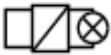 | LED bulb, compact fluorescent bulb (CFL), low voltage halogen bulbs with electronic transformer | LED: 40W (240VAC) / 20W (110VAC)CFL*LVH Electronic transformer: 70W (240VAC) / 35W (110VAC) |
 | Low voltage halogen bulbs with conventional transformer | * |
| Other type of loads | * |
* Please contact Qubino support regarding marked load types: http://qubino.com/support/#email
14. Package Contents
• DIN Dimmer Device
• Installation Manual
15. Z-Wave Command Classes
ZWAVEPLUS_INFO_REPORT_ROLE_TYPE_SLAVE_ALWAYS_ON_V2
GENERIC_TYPE_SWITCH_MULTILEVEL_V1
SPECIFIC_TYPE_POWER_SWITCH_MULTILEVEL_V1
Z-Wave Supported Command Classes:
COMMAND_CLASS_ZWAVEPLUS_INFO_V2
COMMAND_CLASS_VERSION_V2
COMMAND_CLASS_MANUFACTURER_SPECIFIC_V2
COMMAND_CLASS_DEVICE_RESET_LOCALLY_V1
COMMAND_CLASS_POWERLEVEL_V1
COMMAND_CLASS_SECURITY_V1
COMMAND_CLASS_BASIC_V1
COMMAND_CLASS_SWITCH_ALL_V1
COMMAND_CLASS_SWITCH_BINARY_V2
COMMAND_CLASS_SWITCH_MULTILEVEL_V4
COMMAND_CLASS_METER_V4
COMMAND_CLASS_SENSOR_MULTILEVEI_V7
COMMAND_CLASS_NOTIFICATION_V5
COMMAND_CLASS_MULTI_CHANNEL_V4
COMMAND_CLASS_ASSOCIATION_V2
COMMAND_CLASS_MULTI_CHANNEL_ASSOCIATION_V3
COMMAND_CLASS_ASSOCIATION_GRP_INFO_V2
COMMAND_CLASS_CONFIGURATION_V2
COMMAND_CLASS_MARK_V1
COMMAND_CLASS_BASIC_V1
COMMAND_CLASS_SWITCH_MULTILEVEL_V4
Endpoint 1
Device Class:
ZWAVEPLUS_INFO_REPORT_ROLE_TYPE_SLAVE_ALWAYS_ON_V2
GENERIC_TYPE_SWITCH_MULTILEVEL_V1
SPE SPECIFIC_TYPE_POWER_SWITCH_MULTILEVEL_V1
Command Classes:
COMMAND_CLASS_ZWAVEPLUS_INFO_V2,
COMMAND_CLASS_VERSION_V2
COMMAND_CLASS_BASIC_V1
COMMAND_CLASS_SWITCH_ALL_V1
COMMAND_CLASS_SWITCH_BINARY_V2
COMMAND_CLASS_SWITCH_MULTILEVEL_V4
COMMAND_CLASS_METER_V4
COMMAND_CLASS_ASSOCIATION_2
COMMAND_CLASS_MULTI_CHANNEL_ASSOCIATION_V3
COMMAND_CLASS_ASSOCIATION_GRP_INFO_V2
COMMAND_CLASS_MARK_V1
COMMAND_CLASS_BASIC_V1
COMMAND_CLASS_SWITCH_MULTILEVEL_V4
Endpoint 2:
Device Class:
ZWAVEPLUS_INFO_REPORT_ROLE_TYPE_SLAVE_ALWAYS_ON
GENERIC_TYPE_SENSOR_MULTILEVEL_V1
SPECIFIC_TYPE_ROUTING_SENSOR_MULTILEVEL_V1
Command Classes:
COMMAND_CLASS_ZWAVEPLUS_INFO_V2
COMMAND_CLASS_VERSION_V2
COMMAND_CLASS_ASSOCIATION_V2
COMMAND_CLASS_MULTI_CHANNEL_ASSOCIATION_V3
COMMAND_CLASS_ASSOCIATION_GRP_INFO_V2
COMMAND_CLASS_SENSOR_MULTILEVEL_V7
This product can be included and operated in any Z-Wave network with other Z-Wave certified devices from any other manufacturers. All constantly powered nodes in the same network will act as repeaters regardless of the vendor in order to increase reliability of the network.
COMMAND_CLASS_METER
- Default values:
○ Rate Type = 1 (Import)
○ Scale = 0 (kWh)
16. About Qubino
Qubino is a family of innovative Z-Wave devices, many of them the smallest of their kind. Numerous breakthrough innovations, 100% quality control, and responsive customer service make Qubino the number one choice for making your life more comfortable.
Qubino enables you to transform – inexpensively and invisibly – any traditional electric device into a smart, connected one that you can control with your smart phone. Qubino devices are simple to install and use, but also extremely versatile - they offer a wealth of additional features and parameters for you to play with.
We love helping people who enjoy creating new ideas for their home and then using their hard work and skill to turn those ideas into reality. We admire their passion and resourcefulness. We do our best to supply you with products that will enable you to create a unique and special home for yourself. We innovate so that you can be free to make the smartest home possible. With just a touch of magic.
"Simple is smart." We believe it is smart to make complex things simple. But only when this means simple for our customers, not for ourselves. We think a lot so that you won't have to when it comes to installing or using our devices.
For more information visit: www.qubino.com

About Z-Wave:

The Z-Wave protocol is an interoperable, wireless, RF-based communications technology designed specifically for control, monitoring, and status reading applications in residential and light commercial environments. Mature, proven, and broadly deployed (with over 50 million products sold worldwide), Z-Wave is by far the world market leader in wireless control, bringing affordable, reliable, and easy-to-use 'smart' products to millions of people in every aspect of daily life.
Source: www.z-wavealliance.org
17. Safety Information
For Qubino, safety is first, so we have prepared lots of safety tips and information that can be found throughout this manual.
To ensure your safety, please read this manual carefully before installing the device; follow the instructions exactly. The manufacturer (GOAP d.o.o. Nova Gorica) shall not be legally responsible for any equipment damage or personal injury caused by incorrect installation or operation other than that covered in this manual.

① Please check the Technical Specifications and Electrical Diagram chapters, as well as fuse requirements in the Installation chapter before installing the device.
- DIN Dimmer - Available Frequencies
| ORDERING CODE(MODEL NUMBER) | POWER SUPPLY FREQUENCY | Z-WAVE FREQUENCY* |
| ZMNHSD1 | 50 Hz | 868,4 MHz |
| ZMNHSD2 | 50 Hz | 921,4 MHz |
| ZMNHSD3 | 60 Hz | 908,4 MHz |
| ZMNHSD4 | 50 Hz | 869,0 MHz |
| ZMNHSD5 | 50 Hz | 916,0 MHz |
| ZMNHSD6 | 50 Hz | 868,4 MHz |
| ZMNHSD7 | 50 Hz | 919,8 MHz |
| ZMNHSD8 | 50 Hz | 865,2 MHz |
| ZMNHSD9 | 60 Hz | 922,5 MHz |
| ZMNHSDA | 60 Hz | 919,7 – 921,7 – 923,7 MHz |
| ZMNHSDB | 50 Hz | 868,1 MHz |
| ZMNHSDC | 60 Hz | 868,1 MHz |
| ZMNHSDD | 60 Hz | 919,8 MHz |
| ZMNHSDE | 50 Hz | 920,9 MHz |
*You can check the Z-Wave frequency in your country here:
https://www.silabs.com/products/wireless/mesh-networking/z-wave/benefits/technology/global-regions?cid=nat-acq-zwv-041818
19. Important Disclaimer
Z-Wave wireless communication is not always 100% reliable. This device should not be used in situations in which life and/or valuables are solely dependent on its functioning. If the device is not recognized by your gateway (hub) or shows up incorrectly, you may need to change the device type manually and make sure your gateway (hub) supports multi-channel devices. Contact us for help before returning the device: http://qubino.com/support/#email
20. Warning
Do not dispose of electrical appliances as unsorted municipal waste, use separate collection facilities. Contact your local government for information regarding the collection systems available. If electrical appliances are disposed of in landfills or dumps, hazardous substances can leak into the groundwater and get into the food chain, damaging your health and well-being. When replacing old appliances with new ones, the retailer is legally obligated to take back your old appliance for disposal free of charge.
21. Regulations
FCC COMPLIANCE STATEMENT:
This device complies with part 15 of the FCC Rules. Operation is subject to the following two conditions: (1) This device may not cause harmful interference, and (2) this device must accept any interference received, including interference that may cause undesired operation NOTE: This equipment has been tested and found to comply with the limits for a Class B digital device, pursuant to part 15 of the FCC Rules. These limits are designed to provide reasonable protection against harmful interference in a residential installation. This equipment generates, uses and can radiate radio frequency energy and, if not in-stalled and used in accordance with the instructions, may cause harmful interference to radio communications. However, there is no guarantee that interference will not occur in a particular installation. If this equipment does cause harmful interference to radio or television reception, which can be determined by turning the equipment off and on, the user is encouraged to try to correct the interference by one or more of the following measures: —Reorient or relocate the receiving antenna. —Increase the separation between the equipment and receiver. —Connect the equipment into an outlet on a circuit different from that to which the receiver is connected. —Consult the dealer or an experienced radio/ TV technician for help.
Legal Notice
This user manual is subject to change and improvement without notice. GOAP d.o.o. Nova Gorica reserves all rights to revise and update all documentation without any obligation to notify any individual or entity.
Declaration of Conformity
Qubino DIN Dimmer device is in compliance with the essential requirements and other relevant provisions of the Low voltage (LVD) Directive (2014/35/EU), Electromagnetic Compatibility (EMC) Directive (2014/30/EU), Radio Equipment Directive (2014/53/EU), Directive RoHS 2 (2011/65/EU) and Directive ErP (2009/125/EC).
WEEE
According to the WEEE (Waste electrical and electronic equipment) Directive, do not dispose of this product as household waste or commercial waste. Waste electrical and electronic equipment should be appropriately collected and recycled as required by practices established for your country. For information on recycling of this product, please contact your local authorities, your household waste disposal service or the shop where you purchased the product.

NOTE: User manual is valid for DIN Dimmer version P3 and above (Px is part of P/N)!
Example: P/N: ZMNHSDx HxSxP3
Goap d.o.o. Nova Gorica
Ulica Klementa Juga 007, 5250 Solkan, Slovenia
E-mail: info@qubino.com
Tel: +386 5 335 95 00
Web: www.qubino.com
Date: 12.3.2018; V 2.3



- QUBINO®
- USER MANUAL
- TABLE OF CONTENTS
- WHERE TO BUY
- EN
- INTRODUCTION
- USE CASES
- INSTALLATION EXAMPLES WHERE DIN DIMMER IS INSTALLED ON THE DIN RAIL
- INSTALLATION EXAMPLES WHERE DIN DIMMER IS INSTALLED IN COMBINATION WITH TEMPERATURE SENSOR
- ADDITIONAL FEATURES OF DIN DIMMER WHICH CAN MAKE YOUR LIFE EASIER
- QUBINO DIN DIMMER ADVANTAGES AND HIGHLIGHTS
- ADVANTAGES
- HIGHLIGHTS
- INSTALLATION
- I DANGER OF ELECTROCUTION
- I NOTE
- INSTALLING THE DEVICE ON THE DIN RAIL
- STEP 1 – TURN OFF THE FUSE
- STEP 2 – INSTALLING THE DEVICE
- STEP
- BEFORE QUBINO INSTALLATION
- STEP 4 – ADD THE DEVICE TO YOUR Z-WAVE NETWORK
- INSTALLING THE QUBINO TEMPERATURE SENSOR
- PRODUCT ORDERING CODE: ZMNHEA
- TEMPERATURE SENSOR INSTALLATION EXAMPLE
- DEVICE INFORMATION AND SUPPORT
- WHY IS THIS IMPORTANT
- ELECTRICAL DIAGRAM (110 - 240VAC, 24VDC)
- ADDING THE DEVICE TO A Z-WAVE NETWORK (INCLUSION)
- AUTOMATICALLY ADDING THE DEVICE TO A Z-WAVE NETWORK (AUTO INCLUSION)
- MANUALLY ADDING THE DEVICE TO A Z-WAVE NETWORK (MANUAL INCLUSION)
- REMOVING THE DEVICE FROM A Z-WAVE NETWORK (EXCLUSION)
- REMOVAL FROM A ZWAVE NETWORK (Z-WAVE EXCLUSION)
- OR
- FACTORY RESET
- ASSOCIATIONS
- ASSOCIATION GROUPS
- ROOT DEVICE
- ENDPOINT
- TECHNICAL TERMS FOR SWITCHES
- CONFIGURATION PARAMETERS
- PARAMETER NO. 1 – IN-WALL SWITCH TYPE FOR LOAD 1 (Q) TO CONTROL I
- PARAMETER NO. 5 – WORKING MODE
- PARAMETER NO. 10 - ACTIVATE / DEACTIVATE ALL ON / ALL OFF FUNCTIONALITY
- PARAMETER NO. 11 - TURN LOAD 1 (Q) OFF AUTOMATICALLY WITH TIMER
- PARAMETER NO. 12 - TURN LOAD 1 (Q) ON AUTOMATICALLY WITH TIMER
- PARAMETER NO. 21 - ENABLE/DISABLE THE DOUBLE CLICK FUNCTION
- PARAMETER NO. 30 - RESTORE ON/OFF STATUS FOR Q LOAD AFTER POWER FAILURE
- PARAMETER NO. 40 – WATT POWER CONSUMPTION REPORTING THRESHOLD FOR Q LOAD
- PARAMETER NO. 42 – WATT POWER CONSUMPTION REPORTING TIME THRESHOLD FOR Q LOAD
- PARAMETER NO. 60 - MINIMUM DIMMING VALUE
- PARAMETER NO. 61 - MAXIMUM DIMMING VALUE
- PARAMETER NO. 65 - DIMMING TIME (SOFT ON/OFF)
- PARAMETER NO. 66 – DIMMING TIME WHEN KEY PRESSED
- PARAMETER NO. 67 – IGNORE START LEVEL
- PARAMETER NO. 68 – DIMMING DURATION
- PARAMETER NO. 110 – TEMPERATURE SENSOR OFFSET SETTINGS
- PARAMETER NO. 120 – TEMPERATURE SENSOR REPORTING THRESHOLD
- COMPATIBILITY WITH Z-WAVE GATEWAYS (HUBS)
- TECHNICAL SPECIFICATIONS
- TOGGLE SWITCH MODE
- BULB TYPES WHICH SUPPORT DIMMING FUNCTION
- PACKAGE CONTENTS
- Z-WAVE COMMAND CLASSES
- Z-WAVE SUPPORTED COMMAND CLASSES
- DEVICE CLASS
- COMMAND CLASSES
- ABOUT QUBINO
- ABOUT Z-WAVE
- SAFETY INFORMATION
- IMPORTANT DISCLAIMER
- WARNING
- REGULATIONS
- FCC COMPLIANCE STATEMENT
- LEGAL NOTICE
- DECLARATION OF CONFORMITY
- WEEE
Brand : Qubino
Model : DIN Dimmer
Category : Light dimmer