
BD980 - Audio effect EVENTIDE - Free user manual and instructions
Find the device manual for free BD980 EVENTIDE in PDF.


| Product Type | Broadcast Digital Delay Line |
| Brand | EVENTIDE |
| Model | BD-980 |
| Category | Audio Effect / Broadcast Delay Processor |
| Maximum Delay Time | Up to 10 seconds, selectable 4, 6, 8, or 10 seconds via dipswitch |
| Delay Resolution | 1 millisecond or 20 microseconds (dipswitch selectable) |
| Audio Inputs | Two balanced XLR connectors (stereo), pin 2 signal - phase, pin 3 signal + phase |
| Audio Outputs | Two balanced XLR connectors (stereo) |
| Channels | 2 (stereo), mono operation supported via dipswitch |
| Controls | Power, Line In, Dump, Wait & Exit, Ramp-to-Zero, Catchup/Manual Delay, Max Delay, 32-position Catchup Rate switch |
| Display | Alphanumeric delay time/status display and audio level bargraphs |
| Remote Control | Rear panel DIN plug for remote Dump, Wait & Exit or Ramp-to-Zero, plus external relay outputs |
| Serial Port | Optional interface for complete remote control |
| Power Supply | AC 120/240 V selectable, IEC connector with built-in fuse |
| Cooling | Internal fan; adequate ventilation required |
| Mounting | Rack mountable; rear support recommended |
| Tamper-Proofing | Internal dipswitch can disable all front panel switches except Dump |
| Self-Test | Built-in diagnostic self-test mode with test menu |
| Catchup Modes | Selectable oscillator-and-pause or pause-only catchup rates |
| Time Compression | Timesqueeze function can shorten or lengthen program running time |
| Relay Outputs | Dump and Exit relays for switching low-voltage control signals |
| Maintenance | Keep ventilation clear; clean exterior with a soft dry cloth |
| Safety | Grounded power cord required; never remove grounding pin |
| Repairability | Repairs by authorized Eventide service; internal level controls adjustable |
| Documentation | Original operator's manual (PDF) available |
Frequently Asked Questions - BD980 EVENTIDE
User questions about BD980 EVENTIDE
0 question about this device. Answer the ones you know or ask your own.
Ask a new question about this device
Download the instructions for your Audio effect in PDF format for free! Find your manual BD980 - EVENTIDE and take your electronic device back in hand. On this page are published all the documents necessary for the use of your device. BD980 by EVENTIDE.
USER MANUAL BD980 EVENTIDE
OPERATOR'S MANUAL
EVENTIDE BD-980
DELAY LINE
May 1986
EVENTIDE INC.
1 ALSAN WAY
LITTLE FERRY, NJ 07643
201-641-1200
WARRANTY REGISTRATION FORM
MODEL BD-980 BROADCAST DIGITAL DELAY
SERIAL NUMBER:____
OPTIONS:
PURCHASE DATE:____
(day)
(year)
PURCHASER:
(company name)
(contact person for application notes or other data)
(street address)
(city)
(state)
(zip code)
(area code)
(telephone number)
STATION CALL LETTERS:
AM ( )
FM ( )
[NO TEXT]
AM ( )
FM ( )
SOLD BY:
(dealer's name and address)
How did you learn of Eventide equipment?
Site where equipment will be located: STUDIO ( ) TRANSMITTER ( ) BOTH ( )
Is this site the same location as the address for PURCHASER? YES ( ) NO ( )
Any comments?
Would you like literature about:
H-969 Harmonizer (tm)
( )
SP2016 special effects Processor and reverb ( )
BD931/932 Broadcast Digital Delay ( ) H-949 Harmonizer ( )
TABLE OF CONTENTS
INTRODUCTION 1
SPECIFICATIONS 2
FRONT PANEL INDICATORS AND CONTROLS
ALPHANUMERIC DISPLAY 4
PUSHBUTTON SWITCHES 4
TAMPER-PROOFING 5
REMOTE OPERATION 6
REAR PANEL CONNECTORS
AC CONNECTOR AND LINE FUSE 6
AUDIO INPUT/OUTPUT CONNECTORS 6
INPUT LEVEL SETTING 7
SYSTEM INTERCONNECTION 7
REMOTE CONTROL CONNECTORS 8
CATCHUP MODE OPERATION
DUMP BUTTON 9
WAIT & EXIT BUTTON 9
RAMP-TO-ZERO BUTTON 10
DUMP DURING WAIT & EXIT OR RAMP-TO-ZERO 10
MAX DELAY DURING WAIT & EXIT OR RAMP-TO-ZERO 10
CATCHUP/MANUAL BUTTON DURING CATCHUP MODE 10
TIMESQUEEZING 11
CATCHUP RATE SWITCH
USE AND THEORY 12
CHOOSING A SETTING 13
MANUAL DELAY MODE OPERATION
DELAY TIME DISPLAY 14
SETTING THE DELAY TIME 14
TRYING OUT THE BD-980 15
USING SELF-TEST MODE
INTRODUCTION 17
TEST DESCRIPTIONS 18
APPENDIXES
-
DUMP AND EXIT RELAY OPERATIONS 21
-
DUMP LAMP 21
-
DIPSWITCHES 21
-
INTERNAL LEVEL SETTING 22
-
DIN PLUG (REAR PANEL REMOTE) 23
-
SERIAL PORT 24
-
IS IT NORMAL IF.....? 24
LIMITED WARRANTY 26
INTRODUCTION
The BD-980 is designed to enable the broadcast licensee to prevent obscene and/or libelous material from being transmitted over his facilities. It does this by automatically delaying program material by up to 10 seconds, allowing time for the monitoring operator to make the decision as to whether the material being delayed fits in either category.
If objectionable material is heard, either of two methods may be used to ensure that the material is not aired. The first method is standard: a taped jingle, censor's beep, or announcement is placed on the air and the delay line output is temporarily cut off. The second method is unique: patented electronic circuitry allows the entire contents of the unit to be "dumped" and the program resumed without interruption. The delay time is automatically increased after the "dump" occurs. Circuitry is provided, and can be used if desired, to prevent uncontrolled sources such as telephone callers from being aired until the delay time is again long enough to provide protection.
The unit may also be used for production applications as a straight delay line. Short delays may also be useful to synchronize audio and video in cases where video is transmitted by satellite and audio via land-line.
Finally, the BD-980 has some new, special functions: the WAIT & EXIT function can be used to synchronize to a network or live signal feed and the RAMP-TO-ZERO function can be used to decrease the delay time to zero gradually after it is no longer needed for a safety margin. This function can also be used to "Timesqueeze," or shorten, the running time of program material.
Compared to the traditional method of using tape loops for delay, the BD-980 exhibits greater reliability, better and more consistent signal quality and little or no requirement for operator attention. In many cases, the BD-980 has a lower monetary cost than a high-quality tape machine and frees the tape machine for other applications. Also, the unique variable delay capabilities of the unit are not available when a tape recorder is used.
This manual discusses the use and operation of the BD-980. All of the functions are presented explicitly, which may make the manual seem somewhat forbidding. However, the unit is very simple to use, and the apparent complexity is due to our urge to offer complete and accurate information.
IF YOU DON'T WANT TO READ THE WHOLE MANUAL, BE SURE <<<
TO READ AT LEAST THE FOLLOWING BRIEF PARAGRAPHS <<<
INSTALLATION: The BD-980 requires proper ventilation. Even though it has a fan, room around the unit is required for proper ventilation. DO NOT place it above a heat source such as a power amplifier. If the unit is ever transported, it should not be in a case where the rear of the unit is unsupported. If possible, we recommend that the rear of the unit be supported even when it is mounted in an equipment rack.
LINE or MAINS voltage selection: BE SURE THAT IT IS CONFIGURED CORRECTLY! See the REAR PANEL CONNECTIONS section of this manual for more information. Connecting a 115-V unit to 230 V will certainly damage it.
FRONT PANEL INDICATORS AND CONTROLS
Most of the functions of the BD-980 are controlled by six pushbutton switches on the front panel. From left to right they are: the LINE IN button, the DUMP button, the WAIT & EXIT button, the RAMP-TO-ZERO button, the CATCHUP/MANUAL DELAY button, and the MAX DELAY button.
Two other controls are located on the right side of the front panel: the POWER switch, which applies AC power to the BD-980; and the CATCHUP RATE SWITCH, a 32-position rotary switch. This switch determines the catchup rate and pause detection parameters, which are used when the delay time is automatically increasing (CATCHUP) or decreasing (CATCHDOWN). There is a special section about this switch later in this manual.
Audio level control is provided by the audio level bargraphs and input level controls, which are discussed later.
ALPHANUMERIC DISPLAY
The alphanumeric display in the center of the front panel has three uses: (1) as a delay warning indicator and time readout, (2) as a display of the delay time which is set manually, and (3) as a general-purpose display when the self-test feature is being used. The display is your way of seeing what the BD-980 is doing at all times and it makes the unit easier to operate.
PUSHBUTTON SWITCHES
LINE IN

The LINE IN switch operates the two internal relays which either pass signals through the unit for processing or completely bypass all processing. The switch is illuminated when the relays are engaged and the BD-980 is processing its input. The relays are initially engaged when the unit is turned on.
To disengage the relays and bypass all processing, press the LINE IN switch or turn off the power to the BD-980. In this state, the unit is completely bypassed: the XLR inputs are directly connected to the XLR outputs, and are disconnected from the BD-980's active input circuitry. These active inputs are internally grounded.
CATCHUP MANUAL DELAY

The CATCHUP / MANUAL DELAY switch selects one of the two operating modes of the BD-980.
CATCHUP mode provides the "dump" or obscenity deletion feature and two other automatic delay changing functions. When the BD-980 is first powered up, CATCHUP mode is automatically selected.
MANUAL DELAY mode allows the BD-980 to behave as a normal digital delay line. You can enter and exit the MANUAL DELAY mode by pressing the CATCHUP / MANUAL DELAY switch. The switch is illuminated in MANUAL DELAY mode.
The three remaining pushbutton switches have different functions for CATCHUP or MANUAL DELAY mode. For CATCHUP mode, the legend printed on each button describes the function. For MANUAL DELAY mode, the red legend under the button describes the function.
| CATCHUP MODE | MANUAL DELAY | |
| DUMP | CURSOR | |
| DUMP | 1. Delay time set = 0. | Moves display cursor to the right in the display window. |
| 2. DUMP relay engages. | ||
| 3. Delay automatically begins to increase or "catchup." | ||
| CURSOR | ||
| WAIT & EXIT | RAISE | |
| WAIT & EXIT | 1. Waits an amount of time equal to the current delay time. | Increments the numeral which is overlaid by the cursor in the display window and changes the delay time. |
| 2. Delay time set = 0. | ||
| 3. EXIT relay engages. | ||
| RAISE | 4. User is asked to press EXIT button again to initiate delay increase. | |
| 5. EXIT relay is disengaged when the button is pressed. | ||
| RAMP TO ZERO | LOWER | |
| RAMP TO 0 | 1. Reduces delay to zero by a "catchdown" process which is exactly the reverse of the "catchup" process. | Decrements the numeral which is overlaid by the cursor in the display window and changes the delay. |
| LOWER | 2. User is asked to press the same button again to initiate delay catchup after delay decreases to zero. |
TAMPER-PROOFING
A useful feature of the BD-980 is that all of the switches except the DUMP button can be disabled by setting an internal switch, as detailed in Appendix 3. This is useful when the unit is to be used exclusively as an obacenity deletion device, since the delay cannot be accidentally reduced except by turning the power switch off or pressing the DUMP button.
REMOTE OPERATION
The DUMP and the WAIT & EXIT or RAMP-TO-ZERO buttons may be operated remotely by making the proper connections to the "REMOTE" DIN PLUG on the rear panel and setting the dipswitches properly. See Appendices 3 and 5 for more information.
REAR PANEL CONNECTORS
AC CONNECTOR AND LINE FUSE
The AC voltage selector and line cord connection is located on the extreme left of the rear of the unit. A standard I.E.C. three-conductor power cord is provided with the BD-980. NEVER cut off the grounding pin on the power cord. Removal of the ground can induce hum in the output and it is a potential shock hazard. If the power cord plug is replaced with any other connector, be sure that the wires are connected properly and that a power line ground is provided.
The AC connector has a built-in fuse and line voltage selector. The fuse may be removed by pulling the small lever. Always replace the fuse with a fuse of the value marked on the rear of the unit, unless advised otherwise by the factory.
YOU MUST BE SURE THAT THE LINE VOLTAGE SELECTOR IS SET PROPERLY BEFORE OPERATING THE UNIT. With the power cable removed, you can slide aside the plastic door and expose the voltage selector printed circuit card. This card may be removed with a small pliers and must be oriented so that either the 120- or 240- volt marking is at the TOP of the card. Any other position of this card is incorrect and the unit will not operate. If your local line voltage differs greatly from 120 V or 240 V, a step-up or step-down transformer may be required. In some locations, a voltage-regulating transformer or surge suppressor may be necessary.
AUDIO INPUT/OUTPUT CONNECTORS
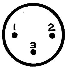
The input and output XLR connectors have "standard" connections: pin 1 is ground, pin 2 is signal - phase and pin 3 is signal + phase. For an unbalanced hookup, the input XLR's pin 2 MUST be grounded and the output XLR's pin 2 should be left open.
INPUT XLR

OUTPUT XLR
INPUT LEVEL SETTING
Proper input signal levels are very important for digital audio equipment in general and the BD-980 in particular. Average signal levels that are too low will degrade the operation of the CATCHUP mode's automatic delay change functions. The signal-to-noise ratio will also be reduced. Signal levels that are too high will cause signal clipping.
Proper levels are easily maintained by viewing the front panel bargraph displays. These displays measure level in 6-dB steps. Average signal levels should not be so high that the display's top elements are continuously lit nor so low that the bottom elements are never lit. The top elements of the display should occasionally flash if the input levels are adjusted correctly.
Input levels may be adjusted from the front panel by using the screwdriver-adjust pots under each bargraph. When the controls are set fully clockwise, the BD-980 clips if input signal levels are greater than approximately +3 dBm. The controls have a fairly slow response time; that is, a large, fast change in rotation causes a much slower change in the actual signal level. This is done so that the controls are effectively very heavily damped and have exceptional long-term stability. They are somewhat easier to adjust in MANUAL DELAY mode.
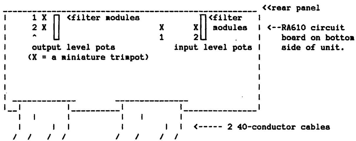
If the pots are set fully clockwise but the top elements of the bargraphs never flash then the input levels at the XLRs are too low. If this occurs, the sensitivity of the inputs should be increased by adjusting the INPUT LEVEL pots on the RA-610 (bottom) circuit board. The location of these pots is shown in Appendix 4. Be sure to examine the BD-980 Alignment procedure in the Technical Manual. A few important notes: Be sure to set the front panel controls fully clockwise before adjusting the internal pots, and be sure to adjust both channels as nearly the same as possible.
The output levels are factory-set at unity gain (1:1 ratio). These settings are internally adjustable as explained in Appendix 4.
SYSTEM INTERCONNECTION
The BD-980 may be used as a normal delay line or in special modes such as catchup, ramp-to-zero, or wait and exit. If the unit is to be employed to replace an existing tape delay, it may be connected in the system in the same manner as the tape unit; that is, substitute the input and output connectors of the BD-980 for those of the tape machine. In this case, when the unit is turned on, the delay initially increases to the maximum delay time and remains there. The DUMP switch should never be touched, and whatever control system currently exists should be used without modification.
If this is a new installation, you probably will want to use the special modes of the unit. In this case, the audio connections are similar to those described in the preceding paragraph. However, you may wish to make use of the relay contacts available at the rear panel REMOTE input for control functions, such as automatically disconnecting the phone line when the DUMP button is pressed. See Appendix 5 for more information about special control functions.
If this installation is replacing the Eventide model BD-955, the connection is the same as the BD-955 except for the additional channel (unless your BD-980 is a mono unit). The REMOTE connector is identical to that on the BD-955 and is wired the same way with the exception of pins 4 and 6, which are usually open circuits on the BD-955 (except for a master/slave "stereo" pair).
If this is a monaural installation, use channel 1 and set dipswitch # 1 ON (see Appendix 3). You can avoid opening the unit to set the dipswitch by connecting the mono input to both rear panel XLR inputs.
>>>>>WARNING<<<<<
In CATCHUP mode, the performance of the automatic delay change functions (catchup and ramp-to-zero) depends on the dynamic signal level and the spectral distribution of the input to the unit. Optimal results are obtained when the input signals are natural; that is, unmodified by compressors, limiters, reverbs, equalizers, and other signal processors. These devices should be placed after the BD-980 in the signal chain.
Performance is also impaired if the stereo input signals are out of phase. The degradation is maximized if there is a complete phase reversal caused by a wiring error. Room reflections and other natural causes can produce out of phase signals between the two input channels, but usually not enough to have an effect on performance. If there is any question of degradation due to phasing problems, set dipswitch #1 ON (see Appendix 3). This action forces the BD-980 to ignore channel 2 when the input signals are analyzed and should clear up any problems due to signal phasing.
The input signals should be as noise-free as is possible. High levels of background noise prevent pause detection and "mask" low level signals.
REMOTE CONTROL CONNECTORS
The rear panel has two remote control connectors: the REMOTE plug and the SERIAL PORT. These are described in Appendixes 5 and 6.
DUMP BUTTON
In CATCHUP mode, pressing the DUMP button immediately sets the delay time to zero. If there is an offensive remark "in" the unit at that time, it is lost. When the DUMP button is released, the delay time will increase or CATCHUP at a rate determined by the CATCHUP RATE SWITCH. The delay time is always the same for both channels.
While the delay is increasing, the right side of the alphanumeric display has a two-digit display of delay time with tenth-second resolution. The left side has a graphical display of delay time. The delay time is proportional to the length of this bargraph-type display, up to about 5 seconds. When the maximum delay time is reached, the display reads: >>SAFE<<.
The lamp in the DUMP button is a third delay time indicator. It is lit only when the delay time is greater than 1/2 of the maximum delay.
The DUMP RELAY (connected to the "REMOTE" DIN plug on the rear panel) is engaged when the button is pressed and is disengaged when the lamp in the DUMP button is illuminated. This relay may be used to disconnect the telephone line.
If the DUMP button is pressed while the delay is catching up, the delay is zeroed and the catchup process begins again. For proper phone line disconnection, the DUMP relay disengages and then re-engages.
WAIT & EXIT BUTTON
The WAIT & EXIT button causes the delay time to be set to zero after a waiting period equal to the current delay time. This function is useful when delaying a talk show, for example, and a network news broadcast or a "live event" such as a helicopter traffic report is about to occur.
If the delay time is 10 seconds, press the WAIT & EXIT button 10 seconds before the event occurs. The BD-980 waits until the 10 seconds of speech still in the unit have been output and then sets the delay time to zero (real-time).
The delay time readout indicates the time remaining in the waiting period. To distinguish this function from normal operation, the bargraph is comprised of "arrows," and the lamp in the WAIT & EXIT switch flashes.
Pin 4 of the REMOTE DIN PLUG is grounded when the delay time is set to zero. This closure can be used to activate external signal switching circuitry.
After the delay time is set to zero, it does not change until the WAIT & EXIT button is pressed. As a reminder, the display alternates between "NO DELAY" and "PRESS-->". When the button is pressed, the delay time begins to increase and pin 4 of the REMOTE DIN PLUG is open-circuited.
If the WAIT & EXIT button is pressed during the waiting period, the countdown stops. The system returns to the condition that it was in before the WAIT & EXIT countdown had started. If the delay had been increasing, this action will resume.
RAMP-TO-ZERO BUTTON
Preasing the RAMP-TO-ZERO button causes the delay time to decrease at a rate proportional to the CATCHUP RATE SWITCH setting. This function can be used to decrease the delay time gradually to zero when the delay is no longer necessary. This is the easiest way to get out of delay. Just push the RAMP-TO-ZERO button and go "on with the show." This function can also be used to change the playing time of a commercial or other source. See "TIMESQUEEZING."
The delay time that is indicated in the display is the actual delay time. Like the WAIT & EXIT function, the bargraph delay time display is composed of arrows and the lamp in the switch flashes to distinguish this function from normal operation.
After the delay time decreases to zero, it does not change until the RAMP-TO-ZERO button is pressed. Like the WAIT & EXIT function, the display alternates between "NO DELAY" and "PRESS-->". When the button is pressed, the delay time begins to increase.
If the button is pressed while the delay time is decreasing, the RAMP-TO-ZERO process is terminated and the delay time begins to increase.
DUMP DURING WAIT & EXIT OR RAMP-TO-ZERO FUNCTIONS
The DUMP button always has precedence over all other functions in CATCHUP mode. Pressing it cancels the WAIT & EXIT or RAMP-TO-ZERO functions, sets the delay to zero, and begins increasing the delay time.
MAX DELAY DURING WAIT & EXIT OR RAMP-TO-ZERO FUNCTIONS
Pressing the MAX DELAY button cancels either of these functions and sets the delay time to the maximum delay available (4, 6, 8, or 10 seconds).
CATCHUP / MANUAL DELAY BUTTON DURING CATCHUP MODE
Pressing the CATCHUP/MANUAL DELAY button causes the unit to enter the MANUAL DELAY mode, terminating any other activity. The delay time does not change.
When returning to CATCHUP mode from MANUAL DELAY mode, no delay change occurs until the MAX DELAY, RAMP-TO-ZERO, WAIT & EXIT, or DUMP button is pressed. If the RAMP-TO-ZERO or the WAIT & EXIT button is pressed, the delay time decreases to zero (or counts down for WAIT & EXIT) from the initial value even if this value is past the dipswitch-set maximum delay time. If the delay time is increasing, the original maximum delay setting takes effect.
This could occur, for example, if the maximum delay had been set to, say, 6 seconds using the internal dipswitches. If a delay of 8 seconds is set in MANUAL DELAY and then the CATCHUP/MANUAL DELAY button is pressed, the unit enters CATCHUP mode. If the RAMP-TO-ZERO button is pressed, the delay begins to decrease from 8.0 seconds to 7.9, 7.8, and so on. If the RAMP-TO-ZERO button is pressed a second time, at 7.0 seconds, the delay begins to increase. As soon as the increase begins, the BD-980 finds that the delay time is greater than that set on the dipswitches. This causes the >>SAFE<< message to appear and the delay time is reduced to 6 seconds.
TIMESQUEEZING
(time compression)
TIMESQUEEZING is a technique that increases or decreases the elapsed time of an audio signal. It is often used to decrease the playing time of a prerecorded commercial by a small percentage.
Timesqueezing usually is accomplished by altering the speed of a tape machine and then altering the pitch reciprocally using, for example, an Eventide Harmonizer (R). The output of the Harmonizer is re-recorded on a fixed-speed tape machine. The BD-980 can Timesqueeze (R) without a Harmonizer or a variable-speed tape machine since its operation naturally increases or decreases elapsed time. There are a few limitations on what can be done, however, and some experimentation may be required for best results.
The removal of 2 extra seconds from a nominally 30-second commercial is an example of a Timesqueeze application. To remove the extra seconds, first connect the BD-980 in a signal path between two tape machines. The tape machine connected to the BD-980's input is used to play the source material and the second tape machine re-records the BD-980's output. Using MANUAL DELAY mode, set the delay time to 2.0 seconds. Press the CATCHUP/MANUAL DELAY button again to return to CATCHUP mode. Set the CATCHUP RATE SWITCH to the 3 o'clock position. Start the two tape machines and when the source material begins, press the RAMP-TO-ZERO button. As the delay time decreases toward zero, 2 seconds of elapsed time are removed from the source material.
Note that the delay time must decrease to zero before the source material completes in order to remove the entire 2 seconds. This means that some adjustment of the CATCHUP RATE SWITCH may be needed. Ideally, the catchup rate is set so that the time taken to reach zero delay from the initial 2-second delay is equal to the entire playing time of the source material. If not, a tempo change may be heard when the delay time reaches zero before the source material is complete. Normally this won't be noticeable unless a fast catchup rate is used, i.e., when making large changes.
An alternative approach is to set the delay to maximum and allow it to decrease from that point. Since the BD-980 will most likely take longer to reach zero than the source material will take to complete, proper adjustment of the CATCHUP RATE SWITCH can cause several seconds of time compression.
If an increase in elapsed time is required, a similar approach is used. The only difference is that the delay time is allowed to increase instead of decrease. For example, to add 2 seconds, set the delay time to 8.0 seconds in manual delay mode. Press the CATCHUP/MANUAL DELAY button and then press the WAIT & EXIT button twice so that the delay time begins to increase.
The major limitation of Timesqueeze on the BD-980 is that the maximum time compression or expansion (amount to be deleted or added) is limited to 10 seconds. If the material is longer, multiple passes can be made.
CATCHUP RATE SWITCH
The 32-position rotary switch on the right side of the front panel is only used in CATCHUP mode. The switch setting determines how fast the delay time changes when the delay is automatically increasing or decreasing.
USE AND THEORY
One of the two available catchup modes is selected by using the rotary switch. (1) Rotating the switch knob clockwise from top center selects one of 16 "osc & pause" settings. (2) Rotating the knob counterclockwise selects one of 16 "pause-only" settings. The term "osc" does not refer to a real oscillator, but rather to a fixed rate of change that is selected by the switch position. For either mode, the settings nearer to the top of the dial (12 o'clock position) select faster catchup or catchdown speeds and the settings farther clock- or counter-clockwise select slower speeds.
The choice of osc & pause or pause-only mode depends on the type of signal being processed, which will most likely be a human voice.
The human voice has a distinct pattern of voiced and unvoiced sections. Voiced sections of an utterance are those time periods when the vocal chords are excited and produce signals with a measurable pitch. Unvoiced sections occur when air is moving in and out of the vocal tract with little or no vocal chord excitation; or during a pause in speech. The pronunciation of the letters "O" and "F" are examples of voiced and unvoiced sounds, respectively.
The BD-980 analyzes sections of its input and uses the results to produce discreet and unobtrusive changes in delay time. After each section is analyzed, the results are compared to parameters chosen by the setting of the CATCHUP RATE SWITCH. The comparison determines whether each section is voiced or unvoiced.
For voiced sections, the delay time is increased by an amount between approximately 5 and 21 milliseconds if an osc & pause mode is selected. The delay time does not change for voiced (non-pause) sections if a pause-only mode is selected.
If the section was unvoiced, the delay increase is about 20 milliseconds, regardless of the mode. Pauses between words, the intake of breath, and "random" noises such as room or crowd noise (if not too loud) generally are interpreted as unvoiced sounds.
In contrast to speech signals, music usually has few "unvoiced" sections, except during an actual pause. Thus, pause-only mode should not be used with musical inputs since the delay time would increase very slowly.
CHOOSING A SETTING
The "osc & pause" settings are more useful if the input signal contains music in the background or foreground. This mode is also more effective if the input signal is a voice and the speaker speaks quickly or has short or infrequent pauses in his speech. The osc & pause settings cause the unit to change the delay time at a fixed rate, which increases during pauses.
As the knob is rotated farther from center, the catchup rate and the pause threshold decrease. That is, the delay time changes less frequently and pauses must be more "quiet" to be recognized. At the fastest rates, some warblyness in the signal may be noticeable, especially if music is present.
If the input is voice only, the "pause-only" settings are more useful. These settings permit delay time changes ONLY when a pause or "unvoiced" section has been recognized. As the knob is rotated counter-clockwise, the pause threshold and catchup rate decrease, with an effect similar to the osc & pause settings. If a pause-only setting is used, any music or continuous signal present in the input to the unit will usually stop ALL delay change activity.
Regardless of the rotary switch setting, taking longer breaths or occasionally increasing the length of a pause will increase the catch-up speed. However, this is not necessary for proper operation. The advanced signal processing techniques used in the BD-980 make the necessity for the conscious insertion of pauses into speech a thing of the past.
MANUAL DELAY MODE OPERATION
In MANUAL DELAY mode the BD-980 behaves as a stereo digital delay line. The delay time may be set in 1-millisecond or 20-microsecond (one sample) increments, depending on a dipawitch setting (see Appendix 3). The delay time is always the same for both channels. The red labels for the three center switches indicate their function in MANUAL DELAY mode.
DELAY TIME DISPLAY
The DELAY TIME DISPLAY display indicates the delay time to the resolution specified by the dipswitch setting. In the high-resolution mode the delay time can be set in 20-microsecond steps. The alphanumeric display shows the delay time to six significant digits:
1 . 2 3 4 5 6 S <---- S is for seconds.
This delay time is 1.23456 seconds, or 1 second, 234 milliseconds, 560 microseconds. In the low-resolution mode the delay time can be set in 1-millisecond steps and the delay time display has only four digits:
1 . 2 3 4 S E C
The lesser-significant digits (hundreds and tens of microseconds) are internally set to zero when the display is set to low-resolution.
SETTING THE DELAY TIME
The delay time is set by placing the flashing cursor over the digit in the display which you wish to change, and then changing that digit. The cursor may be moved to the right by pressing the CURSOR (DUMP) button.
Press the RAISE (WAIT & EXIT) button to increment the digit that is overlaid by the cursor. Press the LOWER (RAMP-TO-ZERO) button to decrement the digit overlaid by the cursor. The increase or decrease in delay time takes effect immediately. If a digit increases past 9 or decreases past zero, the characters to its left will change to reflect the carry or borrow.
When the delay time changes, the audio at the new delay time is faded in and the audio at the old delay time is faded out over a period of about 3 milliseconds. This action prevents any clicks when changing the delay time.
The delay time may be set to maximum by pressing the MAX DELAY button. An easy way to set the delay time to zero is to press this button and then the RAISE button.
Set the unit up with an input from a console. The signal should originate from a microphone or a tape of someone speaking. If a stereo signal is unavailable, either send the same signal to both channels or use channel 1 and turn ON dipswitch # 1 (see Appendix 3). Be sure that the input signal is at the proper level; see the INPUT LEVEL SETTING section if you are unsure.
You can make connections to the output of the unit if you wish to listen to it. However, you will find that it is difficult to speak when listening to your own voice delayed by a few seconds.
Set the CATCHUP RATE SWITCH to the fastest PAUSE-ONLY setting (slightly counterclockwise from top center). After applying power to the unit, a scrolling "sign-on" message appears in the display. This message identifies the software revision number. It can be terminated by pressing the DUMP button.
Next, the BD-980 automatically begins to increase the delay time. Try speaking into the microphone and note that the catchup speed varies with the speech pattern, as can be seen by observing the numerals in the delay time readout. As the delay time increases past about 0.6 second, a series of "stars" begins to appear. This part of the display provides an indication of delay time which can be seen from a distance. Also note that the lamp in the DUMP switch illuminates at 1/2 of the maximum delay. This is another visible indicator of the amount of delay time currently present.
Try rotating the CATCHUP RATE SWITCH counterclockwise. As this is done, the pause detection sensitivity is reduced. Note that the delay time increase occurs at a slower rate and that pauses in speech must be more pronounced to be recognized.
When the delay time reaches its maximum value, the display reads >>SAFE<<. Press the DUMP button to zero the delay time and begin the catch up process again.
Set the CATCHUP RATE SWITCH to the fastest pause-only mode. Whistle or hum into the microphone so that the delay change stops. Alternatively, switch the input signal to a continuous tone. Either type of signal should stop most or all delay change since few, if any, pauses will occur.
Turn the switch one position clockwise to the fastest OSC & PAUSE setting. At this switch position the BD-980 increases the delay time at its fastest fixed rate. Try speaking into the microphone again and note that the delay time increases at a fixed rate and that the rate increases somewhat during pauses in speech.
Try experimenting with different positions of the CATCHUP RATE SWITCH to discover the most pleasing catchup performance.
Press the MAX DELAY button. The delay time is now at its maximum and there is no delay change. Press the WAIT & EXIT button and watch the countdown to zero. Note that there is NO delay change in the unit's output during the countdown. When the NO DELAY and PRESS--> messages appear, the delay will be in real-time (no delay) again.
Press the WAIT & EXIT button again and the delay time begins to increase toward maximum. This increase works exactly the same as if you had pressed the DUMP button except that the DUMP RELAY is not activated.
Allow the delay time to increase to about 2 seconds and press the RAMP-TO-ZERO button. The delay time begins to decrease. Adjust the CATCHUP RATE SWITCH. Observe that the pause threshold and rate of delay time decrease is altered in the same way as when the delay time was increasing. Press the button again and the delay time begins to increase. Press it again and allow the delay time to decrease to zero. Note that the message is the same as when the WAIT & EXIT function times out, except that the RAMP-TO-ZERO button is flashing. Press the button again and the delay time begins to increase. Again, this is like the DUMP button except that the DUMP RELAY is not activated.
Press the CATCHUP / MANUAL DELAY button and the display changes to the MANUAL DELAY mode display of delay time. Note that the delay time has not changed.
Press the CURSOR (DUMP) button several times and watch the cursor move from the SECONDS digit to the HUNDREDS OF MILLISECONDS digit, and so on. Note that the cursor wraps around to the SECONDS digit after the rightmost digit is passed.
Try increasing and decreasing the delay time using the RAISE (WAIT & EXIT) and LOWER (RAMP-TO-ZERO) buttons. Note the carry and borrow activity in the neighboring digits when you go below 0 or greater than 9 in a particular digit.
Press the MAX DELAY button to set the delay time to 9.999 seconds. Press the RAISE button and the delay time will rollover from this maximum delay to zero. This is the easiest way to zero the delay in MANUAL DELAY mode.
Increase the delay time to 3.000 seconds and then press the CATCHUP / MANUAL DELAY button. The CATCHUP mode display reappears, indicating the same delay time as was set in MANUAL DELAY mode. Press the RAMP-TO-ZERO button and the delay time decreases. If you press the WAIT & EXIT button instead, the display counts down 3 seconds and then the delay time is set to zero.
This is the end of this small tour through the BD-980's operating controls. Please spend as much time as necessary familiarizing yourself with the controls before actually using this product in a live situation.
The BD-980's "self-test" mode can be used to check certain parts of the unit by selecting a test from a menu.
Entering the test mode is possible ONLY during the BD-980's turn-on or startup period when the scrolling "sign-on" message is visible. If the LINE IN button is pressed and held down when the unit's power is turned on, the test mode is entered. The system can be restarted manually without cycling the power switch by pressing the RESET button at the left-rear of the top circuit board (RDT-320). Thus, test mode may also be entered by pressing both the RESET and LINE IN buttons and releasing the RESET button.
The test mode begins by presenting an "instructional" message. Release the LINE IN button when this message is seen. After reading the message, proceed to the TEST MENU by pressing the MAX DELAY button. The message continues to scroll until MAX DELAY is pressed. The message may be reread by pressing the LINE IN button at any time except during the front panel BUTTONS test. The scrolling speed of this and most other messages may be changed by holding down the CATCHUP / MANUAL DELAY button and rotating the CATCHUP RATE SWITCH for the desired speed.
After the MAX DELAY button is pressed, the legend "QUIT" appears in the display. This is the first entry in a menu of several tests. Scroll through the menu by pressing the WAIT & EXIT button to go forward or the RAMP-TO-ZERO button to go backward. A test is selected by pressing the DUMP button when the test name is in the display.
Each test has its own "help" message which is displayed after pressing the DUMP button. The actual test begins when the MAX DELAY button is pressed during the help message.
A test can be stopped by pressing the WAIT & EXIT button while the test is in progress. The one exception is the front panel button test, which is cancelled by pressing BOTH the WAIT & EXIT and the RAMP-TO-ZERO button. When a test is cancelled, the test menu is redisplayed; the displayed test name is the next test in the menu.
The "ALL TSTS" function automatically sequences through most of the tests. The WAIT & EXIT button is pressed to skip an individual test. If the DUMP button is pressed between tests, the automatic sequence is interrupted and the TEST MENU is redisplayed. A prompt between tests allows the user a time period to press the DUMP button. WAIT & EXIT and DUMP may be pressed together to abort a longer test and directly return to the menu.
When in test mode, the front panel buttons have new functions:
LINE IN BUTTON: RETURNS TO INSTRUCTIONAL MESSAGE (note 1)
DUMP BUTTON: SELECTS A TEST FROM THE MENU or
ABORTS AUTOMATIC TEST SEQUENCE.
WAIT & EXIT BUTTON: SCROLL FORWARD IN MENU or
CANCEL AN INDIVIDUAL TEST.
RAMP-TO-ZERO BUTTON: SCROLL BACKWARD IN MENU or PRESS ALONG WITH
EXIT BUTTON TO CANCEL "BUTTONS" TEST. (note 2)
MAX DELAY BUTTON: CANCELS SCROLLING MESSAGES, BEGINS TEST or
BEGINS DISPLAY OF TEST MENU.
CATCHUP/MANUAL BUTTON: SETS SCROLL SPEED PROPORTIONAL TO ROTARY
SWITCH POSITION. (note 1)
NOTE 1: During the BUTTONS test, the LINE IN and CATCHUP/MANUAL buttons have no effect aside from displaying the button's name.
NOTE 2: During the BUTTONS test, the WAIT & EXIT and RAMP-TO-ZERO buttons must be pressed at the same time to stop the test and return to the MENU.
TEST DESCRIPTIONS
Please note: Any tests that were added to those listed here are summarized on pages added after the end of the Operator's Manual.
QUIT
The QUIT function leaves the test mode and begins normal operation. This function has no help message and is executed when the DUMP button is pressed.
ALL TSTS
The ALL TSTS function automatically cycles through all of the functions in the TEST MENU, except for itself, QUIT, and the BUTTONS test. Each function name is displayed, the function is performed once, and the legend **DONE** is displayed. Between the tests, a prompt allows some time to press the DUMP button. If pressed, the automatic sequence is interrupted and the TEST MENU is redisplayed. Individual tests may be skipped while in progress by pressing the WAIT & EXIT button. When all of the tests have been performed, the sequence begins again.
BUTTONS
The BUTTONS function displays the name of each front panel pushbutton switch as the buttons are pressed. When no button is pressed, **NONE** is displayed. Be sure to try all the buttons. Press the WAIT & EXIT and RAMP-TO-ZERO buttons at the same time to end the test.
Certain special functions do not work during this test: Pressing the LINE IN button does not return to the "instructional message" and the CATCHUP/MANUAL button cannot be used to alter the speed of scrolling messages.
MEMORY
The MEMORY function tests the AUDIO RAM on the RDT-320 board. The display shows any errors as well as the location of the bad memory chip. Note that the test terminates after finding the first error.
ROTRY SW
THE ROTRY SW function displays the position of the front panel CATCHUP RATE rotary switch, from 0 through 31. The purpose of this test is to be sure that all of these numbers are not only present, but in the correct order. Rotate the knob through all 32 positions and see that they appear in order. If not, the switch may be broken or the switch wiring may be defective. A momentary disturbance while changing the switch position can be ignored.
When the displayed position is "0", the index mark on the switch's knob should be positioned at the fastest OSC & PAUSE setting (slightly clockwise from top-center). If this is not the case, loosen the Allen screws on the knob and reposition the knob correctly.
DIPSWTCH
The DIPSWTCH function displays the settings of the internal dipswitch mounted near the top center of the front panel circuit board. The number of each switch is displayed if it is ON, and that position is blank if the switch is OFF. For example, with only switch 3 ON, the display would be:
ON: 3
With all five switches on, the display would be:
ON:54321
and so on. Positions 6, 7, and 8 are not testable in this manner. Be sure that the switch settings reflect the options that should be selected. See Appendix 3 for information about dipswitch-selectable options.
DISPLAY
The display function cycles the alphanumeric display through all of its displayable characters. Check to be sure that all characters appear with no missing or broken segments.
LAMPS
The LAMPS function cycles all of the incandescent lamps on and off. Observe that all five lamps (the MAX DELAY button has no lamp) operate correctly.
CMOS RAM
The CMOS RAM function tests the CMOS RAM on the RDT-320 board (ICs 40 and 41). The test gives a pass-fail indication when it is complete.
RELAYS
The RELAYS function cycles all of the unit's relays on and off, displaying the name of each relay as it is tested. A click is heard when each relay is activated. The LINE relay click is louder since two relays are operating.
DEGLITCH
The DEGLITCH function tests the alignment of pot P12, located in the center of the RA610 (bottom) board, near IC 18. P12 adjusts a DC bias in the signal analysis circuit. If P12 is set properly, the display is ***OK***. If not, the TURN CCW or TURN CW message appears and P12 should be adjusted clockwise (CW) or counter-clockwise (CCW) as indicated so that it is in the middle of the range where ***OK*** appears.
If the display is viewed for a long time, an occasional flash of TURN CW or TURN CCW may appear and can be ignored. This effect may occasionally cause one of these messages to appear when this test is executed as part of the "ALL TSTS" sequence.
If the pot cannot be adjusted correctly, reset the unit using the RESET button or by cycling the power off and then on again. Then re-enter test mode and try the test again. If this does not work then there is a real problem.
If any change is made in P12's position, perform the following test:
- Verify that the CATCHUP RATE knob is aligned properly on its shaft as explained in the "ROTRY SW" test.
- Set the CATCHUP RATE switch to the SLOWEST pause-only mode. This is slightly CW from bottom-center, or use the ROTRY SW test to set the switch to position 16.
- Connect a stereo signal feed to the unit's XLR inputs or connect the same signal to both inputs. Use a continuous tone (1 kHz @ 0 dBm) as an input. Be sure that signal levels are correct as explained in the INPUT LEVEL SETTING section of this manual.
- Turn on the unit's power. The NO DELAY message should appear in the display after the sign-on.
- The delay should NOT be increasing since the most sensitive pause-only mode has been selected and there is a continuous signal coming into the unit. The NO DELAY message should remain in the display.
- Press the LINE IN button. The lamp in the button goes out, indicating that unit's input is internally grounded (a very quiet pause, as far as the BD-980 is concerned). The delay time should begin to increase at this time. If not, tweak trimpot P12 so that it does.
- If there is a discrepancy between this test and the DEGLITCH test, this test is more accurate.
APPENDICES
APPENDIX 1: DUMP AND EXIT RELAY OPERATIONS
MANUAL DELAY mode: BOTH relays are always disengaged.
CATCHUP mode: The DUMP relay is engaged when the DUMP button is pressed. The relay disengages when the delay is greater than 1/2 maximum delay. The relay disengages if the WAIT & EXIT, RAMP-TO-ZERO, or MAX DELAY button is pressed. If the DUMP button is pressed while the unit is catching up and the relay is engaged, the relay briefly clicks off and then on again to assure proper phone-line disconnection. The EXIT relay is engaged when the delay is set to zero after the waiting period. The relay remains engaged until the WAIT & EXIT button is pressed.
NEVER USE THE RELAYS WITH HIGH VOLTAGES: USE THEM TO SWITCH LOW VOLTAGES ONLY<
APPENDIX 2: DUMP LAMP
The lamp in the DUMP button is ON when the unit is in CATCHUP mode and the delay time is greater than 1/2 of the maximum delay. The lamp is OFF at all other times.
APPENDIX 3: DIPSWITCHES

Switch 1: OFF-- unit analyzes both channels in CATCHUP mode (default). ON -- unit analyzes channel 1 only. MUST be ON if unit is to be used monaurally or if there is significant out of phase information between the two input channels.
Switch 2: OFF-- all front panel switches work (default). ON -- only the DUMP button is active (tamperproof mode).
Switch 3: OFF-- MANUAL DELAY mode resolution is 1 millisecond (default). ON -- MANUAL DELAY mode resolution is 20 microseconds.
Switch 4: MAXIMUM DELAY SELECT A Switch 5: MAXIMUM DELAY SELECT B
These two switches determine the maximum delay time when the delay is increasing. They also control when the lamp in the DUMP button becomes illuminated (1/2 of the maximum delay). The DUMP RELAY is disengaged when the DUMP LAMP is illuminated.
| SW 4 | SW 5 | MAXIMUM DELAY | LAMP ON/RELAY OFF | |
| OFF | OFF | 10 secs | 5 secs | (default) |
| OFF | ON | 8 secs | 4 secs | |
| ON | OFF | 6 secs | 3 secs | |
| ON | ON | 4 secs | 2 secs | |
Switch 6: no effect
Switches 7 and 8 select whether the WAIT & EXIT or RAMP-TO-ZERO button is remote controlled by pin 6 of the rear panel DIN (remote) plug. DO NOT set both switches ON. If both switches are OFF, pin 6 has no effect.
Switch 7: ON -- Pin 6 remotes the RAMP-TO-ZERO button (default). Switch 8: ON -- Pin 6 remotes the WAIT & EXIT button.
The settings of switches 1 through 5 are examined by the BD-980 once, when the unit is powered up or reset. Thus, the RESET button (top circuit board, left-rear) must be pressed or the power switch must be cycled off and then on again if any dipswitch setting is altered while the unit is operating.
The BD-980 is usually shipped with the following default settings of the dipswitches: 1, 2, 3, 4, 5, 6 and 8 are OFF; and switch 7 is ON.
APPENDIX 4: INTERNAL LEVEL SETTING
The input level pots may be used to increase or decrease the input sensitivity of the BD-980. Be sure that the front panel level pots are set fully clockwise before making any adjustment. Both channels should be adjusted for equal sensitivity. Be careful not to overdrive the input; this may occur if the sensitivity is set so high that the front panel level pots cannot attenuate an input signal below the point at which the BD-980 clips.
The output signal levels may be set with the output level pots. We recommend setting them so that there is unity gain between the input and the output of the unit. Be aware that too much of an increase may cause signal clipping at the output of the BD-980.
The full alignment procedure is in the Technical Manual.
APPENDIX 5: DIN PLUG
The rear panel "REMOTE" DIN plug can be used for remote control of the DELAY DUMP button and the WAIT & EXIT or RAMP-TO-ZERO button. There are also pins that connect to the EXIT and DUMP relays inside the unit. These relays should ONLY be used to switch low-level control signals, NEVER line voltage.PIN NUMBER
FUNCTION
1 REMOTE DUMP BUTTON: Momentarily connect to ground (pin 7 or 8) to activate the "DUMP" feature exactly the same way as pressing the DUMP button on the front panel. 2 DUMP RELAY normally closed contact. This pin is connected to pin 3 of the DIN plug when the lamp in the DUMP switch is ON (delay time still less than one-half of the maximum value). 3 DUMP RELAY common contact. This pin is connected to pin 2 of the DIN plug when the DUMP lamp is ON, and to pin 5 when the DUMP lamp is OFF (delay time greater than one-half of the maximum value). 4 EXIT RELAY normally open contact. This pin is connected to ground after the WAIT & EXIT function has counted down to zero and the unit's delay time has been set to zero. This pin is an open circuit at all other times. 5 DUMP RELAY normally open contact. This pin is connected to pin 3 of the DIN plug when the DUMP lamp is OFF. 6 REMOTE WAIT & EXIT or RAMP-TO-ZERO BUTTON: Momentarily connect to ground (pin 7 or 8) to activate the "WAIT & EXIT" or "RAMP-TO-ZERO" feature exactly the same way as pressing the front panel button. The choice of WAIT & EXIT or RAMP-TO-ZERO is made by setting dipswitch #7 or #8 ON. See Appendix 3. 7,8 Ground.  DIN PLUG CONNECTION DIAGRAM LOOKING AT REAR OF UNIT FROM OUTSIDEAPPENDIX 6:
SERIAL PORT
The serial port is an optional connector and interface board that allows complete remote control of the unit. The installation of this option may have been performed at the factory or it may be done in the field. Refer to the documentation for this accessory for more information.APPENDIX 7:
IS IT NORMAL IF.....?
Sometimes it may appear that the BD-980 is not working properly. This may only be the result of perfectly normal operational characteristics. This list outlines some of the more common questions that may arise. If there is a question about the internal dipswitch settings, the states of switches 1 through 5 may be checked without opening the unit by using self-test's "DIPSWTCH" test. 1. The BD-980 may react unpredictably if the AC power fluctuates significantly or if the power switch is switched on and off rapidly. Turn the power off and wait at least 10 seconds before turning the power on again to reset the unit. 2. The bottom LEDs of the bargraph audio displays do not go ON at a fixed level. They should illuminate at about -60 dBm, although this figure may be off by as much as +10 dB. The purpose of the display is to show relative levels; it is not a calibrated instrument. 3. The MAX DELAY button sometimes may not work. The BD-980 automatically disables this button at certain times. When in CATCHUP mode, and if the DUMP button has been pressed or if the unit is catching up for the first time after being powered up, the MAX DELAY button is disabled for a time equal to the maximum delay time that you have set (4, 6, 8, or 10 seconds). This is done so that maximum delay cannot be set after a DUMP before the offensive remark has been overwritten in the memory. 4. The catchup mode of the BD-980 is usually able to increase the delay time very unobtrusively. However, a "burble" or other wavering sound may sometimes be heard in the signal. This can occur when the signal source contains frequency components that are very far apart in frequency. For example, a spoken voice or singer with a bass guitar only slightly in the background may cause the guitar to have a wavery sound. A spoken voice with excessive bass boost may also produce this effect. In general, equalization should be performed after the BD-980 in the signal chain. See the "warning" in the SYSTEM INTERCONNECTION section. 5. CATCHUP RATE SWITCH settings that are marked as "slower" may sometimes result in a slightly faster catchup speed. This is normal and is due to the fact that each switch setting is a combination of catchup speed and pause detection parameters. The exact resultant catchup speed is very dependent on the characteristics of the input signal. 6. If the BD-980 acts in any strange and undocumented fashion, we again advise checking the line voltage and ventilation of the unit. Remember, the BD-980 is actually a complex dual-processor computer system. Like a personal or office computer, it is susceptible to line voltage spikes and brownouts. 7. There are two independent crystal-controlled oscillators in the BD-980. One operates at 20.0 MHz and should not cause interference with any of your equipment. The other operates at 89.6 MHz. This may interfere with FM tuners located in the same vicinity, especially if an unshielded antenna lead is near the unit. If necessary, the crystal frequency may be changed by up to a few hundred kHz with no real effect on the BD-980's performance. Contact the factory for assistance if you have this problem. 8. The screwdriver-adjust audio level pots on the front panel have a slow response time. This time may be very long at slow catchup rates. It is easier to adjust them in MANUAL DELAY mode. This slow response time is used for long-term stability reasons. Since these pots are adjusted infrequently, the response time should not be a problem. When the BD-980 is "timing out" during the WAIT & EXIT function, it is very busy accurately counting down the remaining time and the front panel pots are not checked. Thus, any movement of these pots has no effect on signal levels until the countdown is complete. 9. Pin 6 of the REMOTE DIN plug (rear panel) activates both the WAIT & EXIT and RAMP-TO-ZERO functions, activates the wrong function, or has no effect. If one of these symptoms occurs, you should check the settings of dipswitches 7 and 8. IMPORTANT: Only one of these two switches should be ON at any time. See Appendix 3. 10. The maximum delay time is less 10 ten seconds, or is otherwise not as expected. If this occurs, check the settings of dipswitches 4 and 5, which control the maximum delay of the unit. 11. None of the front panel buttons work except the DUMP button. If this occurs dipswitch #2 is probably switched ON. This activates the tamper-proofing feature. See "TAMPER-PROOFING" and Appendix 3. 12. During delay catchup the unit's output sounds very warbly. This may be due to the nature of the program material, or to equalization, limiting, or compression of the input signal before it is applied to the BD-980. Try setting dipawitch #1 ON (see Appendix 3 and the "warning" in the SYSTEM INTERCONNECTION SECTION). 13. If the unit does not pass signals with the power off, check your signal wiring. The bypass relays provide a DC path between input and output when the power is off or when the lamp in the LINE button is off.LIMITED WARRANTY
The BD-980 is built to exacting quality standards, and should give years of trouble-free service. If you are experiencing problems which are not cleared up (or explained as normal) in this manual, your recourse is this warranty.WHAT IS COVERED BY THE WARRANTY
The BD-980 is warranted for a period of one year against defects in material and workmanship. During this period we will repair or replace (at our option) the unit. This means that if the unit fails under normal operation, because of parts that become defective, or because of defects in construction that later become apparent, (such as bad aolder joints, pc traces, etc.) we will repair the unit at no charge for parts and labor. We will also assume a limited responsibility for shipping charges, as detailed later in the warranty. The warranty DOES NOT COVER damage or defects due to accident or abuse. The BD-980 is a complex piece of equipment that does not react well to being dropped, bounced, crushed, soaked, or exposed to excessively high voltages. If the unit becomes defective for these or similar causes, and the unit is deemed to be economically repairable, we will repair it and charge our normal rates. It DOES NOT COVER shipping damage, either to or from Eventide. If you receive a new unit from Eventide in damaged condition, notify us and the carrier; we will arrange to file an insurance claim and either repair or exchange the unit. If you receive a new unit from a dealer in damaged condition, notify them and the carrier. If EVENTIDE received the unit FROM YOU with apparent shipping damage, we will notify you and the carrier. In this case you must arrange to collect on any insurance. We will await your instructions on how to proceed, but will charge for all repairs on damaged units.WHO IS COVERED BY THE WARRANTY
The warranty applies to THE ORIGINAL PURCHASER from an AUTHORIZED EVENTIDE DEALER, providing that the dealer sold a new unit. DEMO units are also covered under warranty under slightly different circumstances (see next page), and units that are USED, or have been used as part of a rental program, are NOT COVERED under any circumstances. It is your responsibility to prove or be able to prove that you have purchased the unit under circumstances that effect the warranty. A copy of your purchase invoice is normally necessary and sufficient for this. If you have any questions about who is an AUTHORIZED EVENTIDE DEALER, call us. UNITS WITH THE SERIAL NUMBER PLATE DEFACED OR REMOVED WILL NOT BE SERVICEDWHEN THE WARRANTY BECOMES EFFECTIVE
The one-year warranty period begins on the day the unit is purchased from an authorized dealer, or, if the unit is drop-shipped from Eventide, on the day shipped, plus a reasonable allowance for shipping delays. This applies WHETHER OR NOT YOU RETURN YOUR WARRANTY FORM. When we receive a unit, this is how we determine if it is under warranty: 1: If the unit was shipped within the past CALENDAR YEAR, we assume that it is, unless there is evidence to the contrary, such as its having been sold used, rented, etc. 2: If the unit was shipped LONGER THAN A CALENDAR YEAR AGO, we assume that it ISN'T UNDER WARRANTY unless: A: The is a warranty form on file showing that it has been purchased within the past year under appropriate conditions. B: You send a copy of your purchase invoice indicating warranty status along with the unit. 3: If the unit was used as a DEMO, the warranty runs from the date that it was received by the dealer. The original purchaser gets the unexpired portion of that warranty. When you send a unit for repair, you should indicate whether or not you believe it to be under warranty. IF YOU DO NOT SAY SO, AND WE CHARGE YOU FOR THE REPAIR, WE WILL NOT REFUND unless the charge was caused by an error on our part. If you believe the unit to be under warranty and you DO SAY SO, but WE DISAGREE, you will not incur any charges until the dispute is resolved. Reading the above, you can see that it is to your advantage to send in the warranty form when you purchase the unit. Also, if we know who you are, we can send you updates, modifications, and advise you of new products. It will also enable you to receive pre-shipment of parts (see next page).WHO PERFORMS WARRANTY WORK
The ONLY company authorized to perform work under this warranty is EVENTIDE, Little Ferry, New Jersey. While you are free to give it to anyone or to work on it yourself, we will not honor claims for payment for PARTS or LABOR from you or from third parties. HOWEVER, we and our dealers do try to be helpful in various ways: 1: Our dealers will assist, usually without charge during the warranty period, in: A: Determining if there IS a problem requiring return to the factory. B: Alleviating "cockpit error" or interconnection problems that may be preventing the gear from operating to its full capability. 2: We are available for telephone consultation if the dealer cannot help. 3: If a part fails during the warranty period, and you wish to replace it yourself, we will normally ship the part immediately at no charge IF your warranty form is on file. We may ask that you return the defective part for failure analysis. RESPONSIBILITY FOR WARRANTY SHIPPINGWITHIN THE 50 UNITED STATES
The properly packed (this is also your responsibility) BD-980 must be prepaid to Eventide's door at no cost to us. We CANNOT ACCEPT COD or collect shipments. A trouble report MUST accompany all returns to expedite repairs. We will return it to you, PREPAID, at OUR EXPENSE, using an expeditious shipping service, normally UNITED PARCEL SERVICE. In areas that are not served by UPS, we will ship by US MAIL. If you are in a hurry, and you want us to use a PREMIUM shipping method, such as air express, be sure you advise us of this and agree to pay shipping charges COLLECT. If you specify a method that does not permit collect or COD shipments, remit sufficient funds to prepay shipping.SHIPPING OUTSIDE THE UNITED STATES
If you purchased the BD-980 from a dealer in your country, consult with them before returning the unit. If you wish to return it to us, please note: 1: The shipping charges must be prepaid to our door. This means that you are responsible for ALL shipping charges, INCLUDING CUSTOMS BROKERAGE. When a unit is shipped to us, it must be cleared through United States Customs, by an authorized broker. YOU MUST MAKE ARRANGEMENTS FOR THIS TO BE DONE. Normally your freight forwarder has a U.S. branch which can handle this transaction. We CAN arrange to clear incoming shipments for you. If you want our assistance, you must NOTIFY US BEFORE SHIPPING goods for repair, giving full details of the shipment, and including a minimum of \$250.00 in U.S. funds to cover the administrative and brokerage expenses. Any balance will be applied to the repair charges or refunded. If a balance is due to us, we will request a further prepayment. 2: ALL SHIPMENTS WILL BE RETURNED COLLECT. If this is impossible because of shipping regulations, or because money is due us, we will request a prepayment from you for the appropriate amount. 3: All funds must be in U.S. dollars. Payment may be effected by checks drawn on a U.S. bank, or by telegraphic fund transfer to our bank. If you send U.S. currency be sure that it is by a method you can trace such as registered mail. If you pay by Letter of Credit, be sure that it affords sufficient time for the work to be done and the L/C negotiated, and that it is is free from restrictive conditions and documentation requirements. 4: WE RESERVE THE RIGHT TO SUBSTITUTE FREIGHT CARRIERS. We will attempt to honor your request for a specific carrier; however, it is sometimes necessary to use a substitute due to difficulties in communication or scheduling.



- OPERATOR'S MANUAL
- EVENTIDE BD
- DELAY LINE
- WARRANTY REGISTRATION FORM
- MODEL BD-980 BROADCAST DIGITAL DELAY
- APPENDIXES
- INTRODUCTION
- FRONT PANEL INDICATORS AND CONTROLS
- ALPHANUMERIC DISPLAY
- PUSHBUTTON SWITCHES
- TAMPER-PROOFING
- REMOTE OPERATION
- REAR PANEL CONNECTORS
- AC CONNECTOR AND LINE FUSE
- AUDIO INPUT/OUTPUT CONNECTORS
- INPUT LEVEL SETTING
- SYSTEM INTERCONNECTION
- WARNING
- REMOTE CONTROL CONNECTORS
- DUMP BUTTON
- WAIT & EXIT BUTTON
- RAMP-TO-ZERO BUTTON
- DUMP DURING WAIT & EXIT OR RAMP-TO-ZERO FUNCTIONS
- MAX DELAY DURING WAIT & EXIT OR RAMP-TO-ZERO FUNCTIONS
- CATCHUP / MANUAL DELAY BUTTON DURING CATCHUP MODE
- TIMESQUEEZING
- (TIME COMPRESSION)
- CATCHUP RATE SWITCH
- USE AND THEORY
- CHOOSING A SETTING
- MANUAL DELAY MODE OPERATION
- DELAY TIME DISPLAY
- SETTING THE DELAY TIME
- TEST DESCRIPTIONS
- QUIT
- ALL TSTS
- BUTTONS
- MEMORY
- ROTRY SW
- DIPSWTCH
- DISPLAY
- LAMPS
- CMOS RAM
- RELAYS
- DEGLITCH
- APPENDICES
- APPENDIX 1: DUMP AND EXIT RELAY OPERATIONS
- APPENDIX 2: DUMP LAMP
- APPENDIX 3: DIPSWITCHES
- APPENDIX 4: INTERNAL LEVEL SETTING
- APPENDIX 5: DIN PLUG
- PIN NUMBER
- FUNCTION
- APPENDIX
- SERIAL PORT
- IS IT NORMAL IF
- LIMITED WARRANTY
- WHAT IS COVERED BY THE WARRANTY
- WHO IS COVERED BY THE WARRANTY
- WHEN THE WARRANTY BECOMES EFFECTIVE
- WHO PERFORMS WARRANTY WORK
- WITHIN THE 50 UNITED STATES
- SHIPPING OUTSIDE THE UNITED STATES
Brand : EVENTIDE
Model : BD980
Category : Audio effect