2254/R - Audio Compressor AMS Neve - Free user manual and instructions
Find the device manual for free 2254/R AMS Neve in PDF.


| Product Type | Audio Compressor / Limiter |
| Brand | AMS Neve |
| Model | 2254/R |
| Power Supply | 36V DC, 500 mA via dedicated PSU |
| Input Impedance | 10 kOhm, balanced, earth-free |
| Output Impedance | 80 Ohm, balanced, earth-free |
| Maximum Output | +26 dBu into 600 Ohms |
| Frequency Response | 20 Hz to 20 kHz ±1 dB |
| Noise Level | -72.5 dBu (20 Hz to 20 kHz) |
| Limiter Ratio | >100:1 |
| Limiter Level Range | +4 dBu to +20 dBu |
| Limiter Attack Time | 5 ms (slow) or 100 µs to 2 ms (fast) |
| Limiter Recovery Time | 100 ms / 200 ms / 800 ms / Auto |
| Compressor Ratios | 1.5:1, 2:1, 3:1, 4:1, 6:1 |
| Compressor Threshold | -20 dBu to +10 dBu (2 dB steps) |
| Compressor Attack / Recovery | 5 ms / 400, 800, 1500 ms or Auto |
| Gain Make-Up | 0 to +20 dB (2 dB steps) |
| Metering | Input, Output, or Gain Reduction |
| Recall via USB | Neve Recall software (PC/Mac), up to 16 units |
| Dimensions (approx.) | 19-inch rack, 1U |
| Weight (approx.) | 4.5 kg |
| Cleaning | Dry cloth only |
| Safety | Do not expose to water or heat; unplug if unused |
| Fuse | T1.0 A LBC, replace with same value |
| Servicing | Qualified personnel only |
Frequently Asked Questions - 2254/R AMS Neve
User questions about 2254/R AMS Neve
0 question about this device. Answer the ones you know or ask your own.
Ask a new question about this device
Download the instructions for your Audio Compressor in PDF format for free! Find your manual 2254/R - AMS Neve and take your electronic device back in hand. On this page are published all the documents necessary for the use of your device. 2254/R by AMS Neve.
USER MANUAL 2254/R AMS Neve

Neve
2254/R Limiter Compressor
User Manual
527 - 386
Issue 2.4

The 2254/R Limiter Compressor has been designed specifically for the sound recording industry, for the control of programme dynamics. It is based on the classic 2254 series, originally released in 1969.
For your own safety and for the protection of others, please observe the following safety precautions:
- Read these instructions.
• Heed all safety warnings. - Do not use near water.
- Clean only with a dry cloth.
- Do not install near heat sources.
- Do not block ventilation openings.
- Protect the power cord.
• Only use accessories specified by the manufacturer.
• Unplug when unused for long periods of time.
• Refer all servicing to qualified personnel only.
AMS NEVE
Billington Road
Burnley
Lancs
BB11 5UB
England
Phone +44 (0)1282 457011
Fax: +44 (0)1282 417282
Email: info@ams-neve.com
Web: www.ams-neve.com
In the unlikely even that this unit should malfunction or develop a fault, then please register the fault details on our website by clicking the link below.
You will also need to enter the unit's serial number when you do this, so please have this to hand.
http://www.ams-neve.info/crm/fault_report.html
Once the fault details have been registered, one of our technical support team will be in touch via email.
This link should also be used for further operational or technical help, or any general enquiry about the unit.
Table of Contents
Health & Safety Notice
Introduction
Principles of Operation....4
Recall Software....4
Front Panel Controls
Power....5
In....5
Link....5
Limiter section....6
Limit....6
Limit Level....6
Limit Recovery....6
Fast Attack....6
Fast Attack Time....6
Compress section....7
Compress....7
Compress Ratio....7
Compress Threshold....7
Gain Make Up....7
Compress Recovery....7
Meter....8
Rear Panel
Line Input....9
Output....9
Set Gain....9
Sidechain Link....10
Power DIN socket....10
Fuse....10
USB....10
Technical Earth....11
Chassis....11
Recall Software
Installation for PC....12
Installation for Mac....14
Firmware Upgrade
Selecting a File for Transfer....15
File Downloading....16
Corrupted or Old Firmware....16
Unit Specifications
General....17
Limiter....17
Compressor....17
Meter....17
The 2254/R Limiter Compressor is a sophisticated and powerful tool for the control of programme dynamics, and has been designed specifically for the sound recording industry.
To this end, considerable range of control is provided within a small unit whilst adhering to high standards of performance.
It is based on the classic 2254 series originally released in 1969.
Principles of Operation
A single control element is used, capable of some 50dB of gain change with low distortion and noise.
This element is driven by two independent sidechains – one of which acts a limiter and the other which acts as a compressor. Each of these functions operates in a closed loop and may be used in isolation or together.
- The Compressor sidechain samples the programme level before the output line amplifier, thus enabling make-up gain to be provided where necessary.
A series of shaping networks are employed to yield five different compression ratios and by controlling the effective sidechain gain, the threshold may be varied over a wide range. - The Limiter sidechain samples the line amplifier output and thus controls the absolute limit of the programme.
A variety of time constants are available to suit the nature of the programme.
Where two 2254/R units are used together to control the left and right signals of a stereo programme, the control voltages from the two sidechains may be linked to ensure that no shift in image takes place.
Recall Software
All of the switches and settings on the unit can be recalled for later reset using the Recall software.
The settings of up to 16 units can be stored and recalled in this way using either discrete USB ports on your computer (or Mac) with one per unit, or using a powered USB hub.
All soft switches are instantly recallable using a single mouse click, while rotary controls are reset manually by matching them to on-screen graphics.
The Recall software is the same as that which is used for the 88 series of Neve outboard units (8801, 8803, 8804 and 8816).


Power
The Neve logo switch to the left of the meter switches the unit on and off. The unit will always power-up in it's last known state.
The button will light red when the unit is on.
In
Lights yellow when selected, and sends the signal through the units circuitry, even if the unit does not have the Limit or Compress functions selected.
The unit constitutes a buffer amplifier having high input and low output impedance.
If unlit, the Input XLR on the rear of the unit is connected directly to the Output XLR i.e. the unit is bypassed.
Link
Lights yellow when selected.
Press this button when you wish to link two 2254/R units together so they can process the Left and Right of a stereo signal, first making sure that the 9-pin Link sockets on the rear of both units are connected together.
See pin-outs information on page 9.
Limiter section

Limit
Lights yellow when selected, and switches the Limiter sidechain in and out of circuit.
Limit Level
May be set in steps of 2dB from +4dBu to +20dBu.
Limit Recovery
There are three preset recovery times (100ms, 200ms & 800ms), plus an automatic setting (AUTO).
In the AUTO position, both the Attack and Recovery times are composite and self-adjusting.
Speeds are rapid for isolated peaks, while remaining slow for persistently high levels, so the impression of a normal dynamic range is preserved as the programme rides on a slowly moving 'gain platform'.
Fast Attack
Lights yellow when selected.
When unlit, the unit has a much slower attack time (5mS), so as to avoid unpleasant effects when processing certain signals such as a percussive piano or vocals.
In this way, a narrow dynamic range may be achieved by feeding high levels into the 2254/R and choosing a low limit level.
Fast Attack may be useful in certain situations, but should always be used with care.
Fast Attack Time
When FAST ATTACK is selected, the attack time can be set from 100µS to 2mS using the associated rotary control.
This control is continuously variable and is fully sweepable between those two values.
If FAST ATTACK is unlit, this control has no function.
Compress section

Compress
Lights yellow when selected, and switches the Compressor sidechain in and out of circuit.
Compress Ratio
Five preset ratios are provided.
• 1.5:1
• 2:1
• 3:1
• 4:1
• 6:1
The control characteristic is shaped such that the onset of compression is smooth and progressive, the true ratio being reached within the first 5 to 10dB above the Threshold.
Compress Threshold
The Threshold point can be varied in 2dB steps from -20dBu to +10dBu, thus a wide variety of effects can be achieved.
Low Ratios operated with a low Threshold will preserve the dynamic range and also achieve a high signal to noise ratio.
A high Ratio with a high Threshold will behave as a partial limiter.
Gain Make Up
When a Threshold point below line level is chosen, it is necessary to add gain beyond the compressor so as to restore the mean programme level. The gain control provides up to 20dB of additional gain in 2dB steps.
Compress Recovery
Four presets are provided:
- 100 mS
- 200 mS
- 800 mS
- AUTO.
In the AUTO position, both the Attack and Recovery times are composite and self-adjusting.
Speeds are rapid for isolated peaks, while remaining slow for persistently high levels, so the impression of a normal dynamic range is preserved as the programme rides on a slowly moving 'gain platform'.
Meter

The programme meter is operated by a simple drive circuit with rapid attack and slow decay times, that correspond to the typical PPM characteristic.
The green led to the right side of the meter will light at a threshold of about -10dBu.
The led turns red when the program reaches a level of +25dBu, indicating imminent clipping.
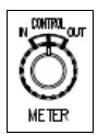
The meter can be set to display either the Input signal level (In), Output signal level (Out) or the amount of gain reduction applied to the signal by the compressor and limiter in total (Control).
This selection is set with the adjacent Meter knob.

Line Input
Input XLR.
| Pin 1 | Screen |
| Pin 2 | Hi |
| Pin 3 | Low |
Output
Output XLR.
| Pin 1 | Screen |
| Pin 2 | Hi |
| Pin 3 | Low |
Set Gain
This trim pot (situated next to the Output XLR) allows you to set the overall gain of the unit to be 0dB in and 0dB out.
This is useful, if for example, the load of the unit connected to the Output is 600Ω .
This would mean the level of the unit would drop by about 1dB, so the Gain Trim allows you to compensate for this.
The default factory setting is 0dB in, 0dB out, with a load of 100kΩ.
Sidechain Link
Links the sidechains of two or more 2254/R units so that they can all work with reference to the same sidechain.

Unit 1
Unit 2
Unit 3
For example, when each unit is processing the Left and Right of a stereo image, this prevents sudden and unexpected changes to one side of the image, so the stereo image is maintained.
This link carries the total of the compressor and limiter sidechains, and the compressor with the highest amount of gain reduction will apply it's gain reduction to the others.
NB:
Care must be taken when wiring these connectors, and the pins should never be shorted to Ground, to the unit chassis, or to each other.
NB:
These 9-pin connectors should only ever be inserted into (or removed from) the unit with the power OFF.
Power DIN socket
The unit requires 36v DC, and this 8 pin DIN socket should only be connected to the power supply provided with the 2254/R.
It is not possible to insert the power connector into this socket incorrectly.
Please refer to the adjacent diagram for connector orientation.
Fuse
A T1.0 amp LBC fuse is fitted.
In the event of the unit failing to power up, this fuse should always be checked first.
The fuse should always be replaced with one of the same value.
USB
The USB socket is a Type B connector used to connect the 2254/R to a PC or Mac for storing & recalling unit settings.
!! WARNING !!
Connections to technical earth and changes to grounding should only be carried out by qualified personnel.
Technical Earth
The grounding of the unit can be set in two different ways:
With this switch in the Off position the chassis of the unit is connected to the mains earth via the power supply.
With the switch in the On position the chassis of the unit should be connected to the studio technical earth using the adjacent Chassis connector.
For safety reasons the chassis is NOT disconnected from the mains Earth but is connected through a resistor capacitor filter.
Chassis
Connect this to your studio earth, and switch Technical Earth On.
Recall Software

Neve Recall software allows settings from the 2254/R to be stored on a PC or Mac and recalled for later use.
The Recall software can also be used for all the units in the 88 Outboard range including 8801, 8803, 8804 & 8816.
Multiple units can be stored and recalled together, up to a total of 16 units in any combination.
NB: When connecting via a USB hub, a powered hub must be used, and not a passive one.
Please see the Recall Manual for further details.
Installation for PC

Insert the CD into the drive and the Setup program should automatically launch.
If the application fails to launch automatically on inserting the CD, then go to the CD Drive in Windows Explorer and double-click the
NeveRecall.msi file or the setup.exe file to launch the Setup program manually.

▶ Click Next.
▶ Click I Agree, then click Next.
If you click I Do Not Agree, the install procedure will terminate.

The installation programme will select a default location for files to be copied and created to.
▶ Click Next to keep the default location, or click Browse to select another location.

▶ Click Next.

▶ Tick as desired then click Next.

▶ Click Install.

The install will start and the progress displayed.

If you wish to launch Recall, tick the Launch Neve Recall box.
▶ Click Finish.
The software will now be ready to use, and will be accessible from Start Menu / Programs / Neve Recall / Neve Recall, or from the Recall icon on the Windows Desktop.
Installation for Mac

Insert the CD containing the software into the Mac, and the install programme will launch automatically.
▶ Click Continue.

Select the location where you wish the software to be installed to.
▶ Click Continue.

▶ Click Upgrade, and the software will start to install.

The progress bar will show the state of the installation.
▶ Once completed, click Close.
The software is now ready to use.
New Versions of Recall Software for Mac
Where you wish to install a new version of the Recall software on a Mac, you will need to uninstall the previous version first and remove some files:
From the Applications folder, move the Neve Recall folder to the Trash;
From the //System Library/Extensions folder, move Neve8816.kext to the Trash (move this file, regardless of the actual outboard units you may have connected via USB)
From the //Library/Receipts folder, move Neve Recall.pkg to the Trash.
You will now be able to install the new version.

In order to get the most from your Neve unit, the latest firmware should be installed.
Upgrading your software is a simple process with on screens prompts to guide you.
▶ Start the Recall software.
On the main screen, right-click the window title bar (Mac users select Recalls)
▶ Click Upgrade Firmware.
▶ Select the file to transfer.

You will be prompted about removing other units.

When updating units, only the unit that is being updated should be connected via USB. All other units should have their USB disconnected.
Even if you are updating two units of the same model, they should be connected individually and updated in two separate operations. If more than one unit is connected via USB when the Update is about to be performed, a screen will prompt you to disconnect the other units.

A prompt screen will confirm the software number & version you should select, and display the current version of firmware for the unit.
▶ Click OK.
Selecting a File for Transfer

The Open File dialog will appear.
To locate the firmware file, browse to the location:
• PC users: C:\Program Files\Neve Recall\Firmware
• Mac users: Applications\Neve Recall\Firmware
The file names follow the format down_88XY_V.hex where XY are the last two digits of the 88 unit name (e.g. '16' for 8816) and V is the software version number.
A typical filename could be down_8804_3.hex.
▶ Double click on the latest filename which matches your unit.
If an incorrect file is selected the user will be prompted to select another file.
File Downloading

Once the file is selected, the transfer will begin and the Recall screen will display that the download is under way.
This process may take up to two minutes for each unit.

Upon completion, the message Firmware Update Successful will be displayed.
▶ Click OK to continue.
You can continue to update other units successfully without restarting Recall, but the Recall software must be restarted once this process is finished.
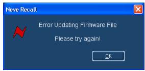
If the transfer fails (for example if the USB is removed by accident or power is lost to the unit), a warning message will prompt to the user to try again.
If Recall is started with a unit that has no firmware, the user will be prompted to upgrade the firmware, as the unit cannot be used in Recall unless the firmware installation is successful.
Corrupted or Old Firmware
If the firmware is corrupted or the unit has an old version of firmware, a prompt will appear upon starting the Recall software to indicate that firmware must be updated before the user can proceed.
The process described above can then be followed to update the latest firmware.
| General | |
| Power | 500 mA, 36 volts DC |
| Input | 10k ohm, bridging, balanced, earth free |
| Output | Source Impedance: 80 ohms, balanced & earth free |
| Maximum Output: +26dBu into 600 ohms | |
| Gain | 0dB, preset adjustment |
| Noise | -72.5dBu in the band 20 Hz to 20 kHz |
| Frequency Response | Flat, within 1dB from 20 Hz to 20 kHz |
| Distortion(Typically measured at +8dBu, 800mS Recovery) | 0dBu: 0.03% |
| +15dBu: 0.2% | |
| Limiter | |
| Ratio | >100:1 |
| Level | Adjustable from +4 dBu to +20dBu in 1dB steps |
| Attack Time | 5 mS (slow) or selectable between 100 μS to 2 mS (Fast) |
| Recovery Time | Selectable between 100 mS / 200 mS / 800 mS / Auto |
| Compressor | |
| Ratio | Selectable between 1.5:1 / 2:1 / 3:1 / 4:1 / 6:1 |
| Threshold | Adjustable from -20dBu to +10 dBu in 2 dB steps |
| Attack Time | 5 mS |
| Recovery Time | Selectable between 400 mS / 800 mS / 1500 mS / Auto |
| Gain Make Up | Adjustable Gain make-up available from 0 dB to +20 dB |
| Meter | Switched to indicate either:Gain reduction control (up to 16dB), orInput or Output signal level (-16dBu to +12dBu)Action approximates to that of PPM. |
© 2009 - 2010 AMS Neve Ltd own the copyright of all information and drawings contained in this manual which are not to be copied or reproduced by any means or disclosed in part or whole to any third party without written permission.
As part of our policy of continual product improvement, we reserve the right to alter specifications without notice but with due regard to all current legislation. Disclaimer: The information in this manual has been carefully checked and is believed to be accurate at the time of publication. However, no responsibility is taken by us for inaccuracies, errors or omissions nor any liability assumed for any loss or damage resulting either directly or indirectly from use of the information contained within it.
Trademarks: All trademarks are the property of their respective owners and are hereby acknowledged.

- NEVE
- R LIMITER COMPRESSOR
- USER MANUAL
- FOR YOUR OWN SAFETY AND FOR THE PROTECTION OF OTHERS, PLEASE OBSERVE THE FOLLOWING SAFETY PRECAUTIONS
- TABLE OF CONTENTS
- HEALTH & SAFETY NOTICE
- INTRODUCTION
- FRONT PANEL CONTROLS
- REAR PANEL
- RECALL SOFTWARE
- FIRMWARE UPGRADE
- UNIT SPECIFICATIONS
- PRINCIPLES OF OPERATION
- POWER
- IN
- LINK
- LIMITER SECTION
- LIMIT
- LIMIT LEVEL
- LIMIT RECOVERY
- FAST ATTACK
- FAST ATTACK TIME
- COMPRESS SECTION
- COMPRESS
- COMPRESS RATIO
- COMPRESS THRESHOLD
- GAIN MAKE UP
- COMPRESS RECOVERY
- METER
- LINE INPUT
- OUTPUT
- SET GAIN
- SIDECHAIN LINK
- NB
- POWER DIN SOCKET
- FUSE
- USB
- WARNING
- TECHNICAL EARTH
- CHASSIS
- INSTALLATION FOR PC
- INSTALLATION FOR MAC
- NEW VERSIONS OF RECALL SOFTWARE FOR MAC
- SELECTING A FILE FOR TRANSFER
- FILE DOWNLOADING
- CORRUPTED OR OLD FIRMWARE
Brand : AMS Neve
Model : 2254/R
Category : Audio Compressor