Phonogene - Audio Equipment Make Noise - Free user manual and instructions
Find the device manual for free Phonogene Make Noise in PDF.


| Product Type | Eurorack modular synthesizer module (digital audio buffer / sampler / looper) |
| Brand / Model | Make Noise Phonogene |
| Category | Audio Equipment |
| Power Requirements | +12VDC at 70mA, -12VDC at 40mA |
| Eurorack Width | 20HP |
| Audio Buffer | 2MB non-volatile memory |
| Sample Rate Range | 5.5 kHz to 88.2 kHz (variable via Vari-Speed) |
| Recording Time | Approximately 2 seconds at mid-fi setting (longer at lower sample rates) |
| Inputs | Signal input (AC coupled), CV inputs for Vari-Speed, Organize, Slide, Gene Size; pulse inputs for Play, Record, Splice, Gene Shift |
| Outputs | Signal output (10Vpp AC coupled), End of Splice output (4ms pulse) |
| Controls | Panel knobs (Vari-Speed, Organize, Slide, Gene Size, SOS), rotary attenuators/attenuverters, buttons for Record and Splice |
| LED Indicators | Playback direction (forward/reverse), Record status, End of Splice |
| Main Features | Sound on Sound, Splice/Organize, Vari-Speed, Gene manipulation (granular synthesis), Slide, Gene Shift |
| Signal Processing Modes | Tape music tools, microsound tools, granulation, micromontage, broken echo mode |
| Erase Routine | Clears splices and optionally audio buffer |
| Broken Echo Mode | For creating drones, walls of sound, and crude echo effects |
| Compliance | FCC Part 15 Class A, CE |
| Warranty | 1 year limited warranty |
| Installation | Requires Eurorack case and properly formatted bus board with -12V line |
| Maintenance | Clean with a dry cloth; avoid exposure to moisture and excessive heat |
Frequently Asked Questions - Phonogene Make Noise
User questions about Phonogene Make Noise
0 question about this device. Answer the ones you know or ask your own.
Ask a new question about this device
Download the instructions for your Audio Equipment in PDF format for free! Find your manual Phonogene - Make Noise and take your electronic device back in hand. On this page are published all the documents necessary for the use of your device. Phonogene by Make Noise.
USER MANUAL Phonogene Make Noise
PHONOGENE


PHONOGENE
FCC 3
Limited Warranty 4
Installation ----5
Overview 6
Panel Controls 7
Getting Started 10
Recording Process 11
Splice 12
Microsound 13
Chronological Inspection of Sound DNA ----14
PHONOGENE Firmware v.372 Update ----15
Hidden Functions and Routines ----16
Patch Examples 17
Advanced Patch Techniques ----22
Venturing Further 26
FC
CE
This device complies with Part 15 of the FCC Rules. Operation is subject to the following two conditions: (1) this device may not cause harmful interference, and (2) this device must accept any interference received, including interference that may cause undesired operation.
Changes / modifications not approved by the Make Noise Co. could void the user's authority to operate the equipment.
This equipment has been tested and found to comply with the limits for a Class A digital device, pursuant to part 15 of the FCC Rules. These limits are designed to provide reasonable protection against harmful interference when the equipment is operated in a commercial environment. This equipment generates, uses, and can radiate radio frequency energy and, if not installed and used in accordance with the instruction manual, may cause harmful interference to radio communications.
Make Noise warrants this product to be free of defects in materials or construction for a period of one year from the date of purchase (proof of purchase/invoice required).
Malfunction resulting from wrong power supply voltages, backwards or reversed eurorack bus board cable connection, abuse of the product, removing knobs, changing face plates, or any other causes determined by Make Noise to be the fault of the user are not covered by this warranty, and normal service rates will apply.
During the warranty period, any defective products will be repaired or replaced, at the option of Make Noise, on a return-to-Make Noise basis with the customer paying the transit cost to Make Noise.
Make Noise implies and accepts no responsibility for harm to person or apparatus caused through operation of this product.
Please contact technical@makenoisemusic.com with any questions, Return To Manufacturer Authorization, or any needs & comments.
http://www.makenoisemusic.com

About This Manual:
Written by Tony Rolando
Edited by Walker Farrell
Illustrated by W.Lee Coleman
THANK YOU:
DSP Wizard: Tom Erbe; www.soundhack.com
Firmware engineer: Flemming Christensen (Gotharman http://www.gotharman.dk)
Beta Analysts: Aaron Abrams, James Cigler
Test Subject: SurachaiSpiritual Advisor: Richard Devine.
Special Thanx to Curtis Roads for his book "Microsound"
Electrocution Hazard!
Always turn the Eurorack case off and unplug the power cord before plugging or un-plugging any Eurorack bus board connection cable.
Do not touch any electrical terminals when attaching any Eurorack bus board cable.
The Make Noise PHONOGENE is an electronic music module requiring 70 mA of +12VDC and 40 mA of -12VDC regulated voltages and a properly formatted distribution receptacle to operate. It must be properly installed into a Eurorack format modular synthesizer system case.
Go to http://www.makenoisemusic.com/ for examples of Eurorack Systems and Cases.
To install, find 20HP in your Eurorack synthesizer case, confirm proper installation of included eurorack bus board connector cable on backside of module (see picture below), plug the bus board connector cable into the Eurorack style bus board, minding the polarity so that the RED stripe on the cable is oriented to the NEGATIVE 12 Volt line on both the module and the bus board. On the Make Noise 6U or 3U Busboard, the negative 12 Volt line is indicated by the white stripe.

Please refer to your case manufacturers' specifications for location of the negative supply.
The PHONOGENE is a digital re-visioning and elaboration of the tape recorder as musical instrument. It takes its name from a little-known, one of a kind instrument, used by composer Pierre Schaeffer. While it is not an emulation, it does share the primitive, tactile nature of its namesake and expands upon the original concepts. It is informed by the worlds of Musique Concrète (where speed and direction variation were combined with creative tape splicing to pioneer new sounds) and Microsound (where computers allow for sound to be divided into pieces smaller then 1/10 of a second, and manipulated like sub-atomic particles). Having voltage control over every parameter, it is most dynamic as a digital audio buffer for the modular synthesist. The PHONOGENE is comprised of a pair of tool-sets, which work well together. Tape Music Tools allow for sounds to be recorded on the fly, layered using the internal Sound On Sound function, manually cut into pieces using the Splice function, and re-organized with the Organize control. Once it is spliced up, it is possible to create nearly infinite variations of the original loop by modulating the Organize parameter. Vari-Speed allows for the speed and direction of playback to be controlled continuously with one control signal. Gene Size, Gene Shift, and Slide make up the Microsound Tools. Gene Size divides the audio buffer into progressively smaller pieces called Genes (aka particles, grains, granules). A clock signal applied to Gene Shift steps through those pieces in chronological order, while a control signal (such as the Wogglebug Smooth CV) applied to Slide, moves through those pieces in a nonlinear fashion. Using Slide, random access of the audio buffer is possible. Obviously, functions such as Vari-Speed and Organize are useful for Microsound as well, which is why these functions were grouped into one module. The end result is a sampler/looper/audio buffer that is able to exist within a modular synthesizer system, and offer a vast amount of real-time sound manipulation in a fast and tactile way.
PERPECTIVE
There is often the expectation that “bad sounds,” such as clicks, pops, distortions, wrong notes, phase inaccuracies and otherwise, should be impossible with modern musical instruments. Many designers are making instruments which are fool-proof, and which guarantee some specific musical result, thus making it easy to create the same music over and over again. The PHONOGENE does not use this approach. In fact, we have made it very possible to make the “bad sounds” and “mistakes” that have led to some of the greatest moments in musical history (and of course, some of the worst!). With the PHONOGENE, it is possible to Splice sounds in such a way that you hear sharp contrasts, clicks and pops. This is the physics of sound! It is possible to slow down a recording to the point of complete decimation, so that all that remains is trail of digital artifacts. Such are the limitations of digital sound. It is possible to render the source material completely unintelligible, to cut busted loops, to distort digitally, to obscure, to regenerate to the point of almost no signal integrity. This is the nature of the PHONOGENE. If you seek the perfect looping tool, in the most contemporary sense of the word “loop,” then please look elsewhere. If you desire to explore the realm of modular, digital sample manipulation and microsound, read on!

PHONOGENE Panel Controls
- Signal Input Rotary Level Control: For Line Level set at 3:00, and for 10Vpp at set 9:00 CW. Faceplate is marked accordingly.
- Signal Input: Line Level or typical Modular Synth levels acceptable. AC Coupled.
- Sound On Sound CV Input: sets mix of previously recorded Loop with Live Signal input when recording, to allow for Sound on Sound type "overdubs." Also allows for setting monitoring level of Live input signals with previously recorded Loop. May be misused as a Voltage Controlled Crossfader (between Live and Loop) or VCA for\ Loop (no Live Signal). Range 0V to 10V, linear response. Normalized to +10V.
- Sound On Sound Panel Control: with nothing patched to SOS CV Input (which is normalized to +10V) works as standard panel control. With Signal Patched to SOS CV Input, works as attenuator for that signal.
-
Signal Output: 10Vpp (depending upon Signal Input attenuator setting and source material), AC coupled.
6 & 7. Vari-Speed and Splice Indicator LEDs: These LEDs tell user in which direction the PHONOGENE is playing. The LEFT Blue (7) LED indicates reverse playback, right Orange LED (6) indicates forward playback. When no LEDs are lighted, playback is stopped. -
Vari-Speed CV Input: bipolar speed and direction control where 0V stops playback, positive control signal increases playback speed in forward direction, negative control signal increases playback speed in reverse direction. Range +/-4V.
- Vari-Speed Bipolar Panel Control: manual bipolar speed and direction control. When set to 12:00, playback is stopped, turning Clockwise from 12:00 increases playback speed in forward direction, turning Counter Clockwise from 12:00 increases playback speed in reverse direction.
- Vari-Speed CV Input attenuverter: bipolar attenuator for Vari-Speed CV Input.
- Organize CV Input: unipolar control signal input which selects next Splice to be played. he currently selected Splice plays to end before the next Splice is selected. The Vari-Speed and Splice Indicator LEDs (6 & 7) flashes whenever this control ends a new Splice. Range 0V to +5V.
- Organize CV Input Attenuator: unipolar attenuator for Organize CV Input.
- Organize Panel Control: manual unipolar control which selects next Splice to be played. The Vari-Speed and Splice Indicator LEDs (6 & 7) flashes whenever this control ends a new Splice.
- Play Pulse Input: at each rising edge signal applied to Play Pulse Input, PHONOGENE triggers playback. At end of loop or Splice, PHONOGENE looks at Play Pulse Input. If High, it plays again. If Low, PHONOGENE does not play. This Input is normalized to be High. So with nothing patched to Play Pulse Input, PHONOGENE plays continuously. Sees only rising edge of signal. Needs at least 1.5V trigger signal to operate.
- Record Pulse Input: toggles record on/off. When recording from a cleared buffer, the first record cycle sets the record length, so be sure to perform the Erase Routine to achieve a new recording. Sees only rising edge of signal. Needs at least 1.5V trigger signal to operate.
- Record button: manual, momentary button to toggle record on/off.
- Record LED indicator: when lighted, PHONOGENE is recording. When not lighted, PHONOGENE is not recording. When flashing, PHONOGENE has entered the Erase Routine.
- Splice Button: pushing drops splice marker on loop. When loop is Organized, the splices (resulting audio segments) are re-arranged according to the Organize control voltage as the PHONOGENE plays whichever splice is selected by Organize parameter. Since splices may be erased, this process is nondestructive. Holding this button for 3 seconds enters Erase Routine (Rec LED flashes to indicate the Erase Routine).
- Splice Pulse Input: input for using external signal to splice loop. Sees only rising edge of signal. Needs at least 1.5V trigger signal to operate.
- End Of Splice Output: outputs a short 4 ms pulse at the end of each splice. In the absence of Splices, EOS reflects end of loop, which is always present when a recording has been made.
-
End Of Splice LED indicator: lights to give visual feedback of End of Splice.
-
Slide Bipolar Panel Control: manual bipolar panel control for scanning the pieces of sound that result from setting Gene-Size to greater than 10%. Moves/ slides through the Genes (aka grains). Allows for scrubbing of the recorded material and is always dependent upon the Gene Size setting.
- Slide CV Input: bipolar control input for Slide. Range +/-4V.
- Slide CV Input Attenuverter: bipolar attenuator for Slide.
- Gene Size CV Input: unipolar control input setting size divisor of audio buffer, dividing with respect to the buffer size as set by Record or Splice length. This parameter "auto-splices" the recorded material like a machine, with no regard to source material. Operates with great precision and the ability to cut pieces so small that the original source material is completely unintelligible. Nondestructive. At 0V there is no effect. Range 0V to +8V.
- Gene-Size Input Attenuator: unipolar attenuator for Gene Size.
- Gene Shift: clock signal at this input advances PHONOGENE to next Gene, in chronological order. Always dependent upon the Gene Sizesetting. Needs at least 1.5V trigger signal to operate.
- Gene Size Panel Control: manual unipolar control which sets Gene Size divisor.
Erase Routine
It is best to start with a cleared memory. To Reset the PHONOGENE and start fresh you need to enter the Erase Routine, where you may erase Splice markers and the Audio Buffer (aka Loop, aka Recording, aka Sample). To erase all Splices, press and hold Splice button (18) until the Rec LED (17) starts flashing. All Splices are erased once the Rec LED begins flashing. While still holding Splice button, and with the Rec LED still blinking, the audio buffer may be erased as well by pressing REC button (16) once. If you do not press Rec button, then your recorded audio remains, and only the Splices is erased. The PHONOGENE continues to play the loop until you erase, and you should release the Splice button as soon as you have completed your desired Erase Routine.
Signal To Be Captured!
The Signal Input (2) has a gain control (1) that accommodates modular synthesizer signals as well as line level sources. Early electronic music composers often recorded pure Sine waves to tape at different frequencies and amplitudes, and then edited and spliced these sounds into the musical phrases, but this was largely because there did not exist the means to control the electronic sounds. Laboratory instruments were being used as musical instruments, and these tools lacked the vast controls needed for musical expression. The arrival of the VCO, VCA and Sequencer made complete control of Frequency and Amplitude possible, on a time scale determined by the composer. Honestly, the most interesting source material for the PHONOGENE is not your synthesizer, but instead every other sound that surrounds you, so grab a microphone or patch into the internet and find some seemingly mundane sound to massage into a gorgeous, jumbled up symphony of micronoise.
Recording Time and Quality
Audio Buffer is 2MB, nonvolatile, high number of fast read and write cycles. Nonvolatile means the PHONOGENE remembers both samples and splices on power down. The high number of read and write cycles is key to longevity of the module, high speed read and write cycles allow for short sample times, making the microsound possible. Because the record and playback frequency is continuously variable from 88.2khz to 5.5khz by the Vari-Speed control (8, 9, 10), the longest possible recording or loop length, is determined by the speed of Playback/ Record. Therefore, long recordings may be achieved, but at the cost of a lower sample rate, meaning the resulting recordings are of lower sound quality. A “Mid-Fi” setting may be achieved by setting Vari-Speed at around 50%, so that both Vari-Speed and Splice Indicator LEDs (6 &7) are OFF. This records with good quality, a 2 second record length, and allows for a good range of speed variation. Playback is stopped while you record.
Signal OUT
That the PHONOGENE exist within the modular system is a huge advantage. Many Analog Synthesis techniques and processes work well with the PHONOGENE. Creative Filtering, especially Low Pass and Band Pass, are very useful in controlling the textures, clicks, and aliasing of the PHONOGENE. Amplitude Modulation, Echo, Reverbare also commonly suggested post processing techniques in microsound and granular synthesis.
The Record control toggles record on/off. Starting with a Cleared Memory, pressing the RECord Button (16) once (or sending a single Pulse to Record Pulse Input, 15) starts the recording process, and pressing Record Button again (or sending a second, single Pulse to Record Pulse Input) stops the recording process. If the end of the Audio Buffer is reached before the user stops recording, RECord automatically stops. The PHONOGENE begins looping the recording immediately upon completion of the record cycle (assuming the PLAY Pulse IN, 14, is held HIGH, which is the default state when there is nothing patched to the Play Pulse Input). It is necessary to adjust the SOS control (4) so that the desired source (or blend of sources) appears at the Signal OUT. This initial recording sets the loop length, which is always minded, until the Audio Buffer is cleared (see Erase Routine, page 5).
Sound On Sound
Once the initial recording is made, the RECord function then allows for punch In/Out within the loop, and layering of other sounds. Sound On Sound Control (3, 4) sets the balance of the Live Signal and previously recorded Loop Signal. While the PHONOGENE does not record in reverse, it plays back in reverse while recording for Sound On Sound, so it is possible to have two sounds playing in opposite directions. Once SOS is complete, remember to adjust the SOS control so that the desired source (or blend of sources) appears at the Signal Output.
Splicing
The Splice button and Splice Pulse Input (18, 19), allows the user to non-destructively cut the loop into pieces, which are then selected for playback using the Organize parameter (11, 12, 13). To Splice, have the PHONOGENE set to playback the material to be spliced, and use either the Splice Button or Splice Pulse Input to drop Splice markers on the recording as it plays through. When playback loops around to the beginning, the PHONOGENE sees the new Splices, and looks at the voltage set by the Organize control in order to select which Splice to play. To preview your Splices, turn the Organize Panel Control slowly, and observe the Vari-Speed and Splice Indicator LEDs (6, 7) for flashing to indicate new splice found. The newly selected Splice does not play until the currently playing Splice reaches its end, at which point the End Of Splice Output (20) generates a 4 ms pulse and the newly selected Splice begins playing. The Record function minds the boundaries of the currently selected Splice. This allows for replacing sounds within a musical phrase, or creating highly contrasting edits when building sound collages. To initiate Record at the start of Splice, patch the EOS Pulse (20) to Record Pulse Input (15). To erase Splices, enter the Erase Routine (see page 5). It is useful to slow and even stop the sound when Splicing, if precision is desired. To avoid clicks, slow the sound to find spaces or low amplitude regions in which to place Splices. Use your ears. If you want to Splice in real-time, let the loop play a few times, and learn the rhythm, thinking about where the up-beats fall, and try to drop splices on those up-beats. See the “Recycler” patch page 15 for “auto-splicing.”
Another way to splice is to set the Gene-Size control as high as possible (without losing sound), and use Slide to manually scrub the sound. When you get to the desired point, press Splice, and a splices be dropped at the start of the currently playing Gene. Turn Gene-Size back down to 0% and listen to the results. This is a highly useful trick for more precision splices; however, it is not as real-time and just manual dropping them as the loop plays.
It is possible to manually Splice into the microsound range (down to about 10ms). This is an excellent technique to experiment with since it allows for many different sizes, where as Gene Size parameter sets a uniform size for all pieces. Additionally Organize treats Splices differently than the Slide treats the Gene, since Organize waits until the current Splice reaches the end before moving to the next selected Splice. This often has less glitches as the sound is traversed. A world of micromontage awaits.
Re-Organizing Splices
Organize is the one control on the PHONOGENE that is not instantaneous. Turning the panel control or modulating Organize, the Vari Speed and Splice Indicator LEDs (6,7) flash indicating new splice found, however, the newly found Splice is not selected for playback until the currently playing Splice reaches its end, at which point the End Of Splice OUT (20) generates a 4 ms pulse and the newly selected Splice begins playing. The Organize parameter was designed for sequential control sources, such as René or PRESSURE POINTS. The range is smaller than the other control inputs, reflecting the typical 5Vpp range of analog sequencers. It is worth considering that the human ear is more sensitive to incongruences in pure and simple waveforms, so for example, recording a Sine wave of constant amplitude and Splicing results in audible clicks, while recording speech and splicing is not as likely to have audible clicks.
Speed Variation, Direction Variation
There is one control associated with both direction and speed, and that control is Vari-Speed (8, 9, 10). Also there are LED indicators (6, 7) which show direction of playback. At 12:00, Vari-Speed is at 0, and playback is stopped. Neither of the associated LEDs are on. Turning Clockwise from 50% increases playback speed in forward direction, turning Counter Clockwise from 50% increases playback speed in reverse direction. Vari-Speed has a wide range, with increased resolution toward the center of it's range, thus giving the control a nice feel when “braking” playback with a smooth control voltage. For “Wow & Flutter” effects, modulate with greatly attenuated smooth random voltage (such as Wogglebug Woggle CV), setting the on board attenuator nearly to 50% (nulled). Sequencing the speed of playback is also very pleasing when combined with sequencing of the Organize parameter. Stopping Playback, Starting Playback, Re-Triggering Sounds When Vari-Speed (8, 9, 10) is at 50% the PHONOGENE has slowed to a halt. When Vari-Speed is set to greater or less then 12:00, playback starts from where it was halted. The Play Pulse IN also stops and starts playback, but in a very different way. At the end of each loop or splice, the PHONOGENE looks at the PLAY Pulse Input (14), if it is high, then PHONOGENE continues to play, if it is low, PHONOGENE stops at end of loop or splice. In this way, the Play Pulse Input, is always play the loop or splice from the beginning. Play Pulse Input may also be used to re-trigger sounds, since it is essentially looking for a change in state, from low to high. If you send repeated pulses to Play while Vari-Speed is set for playback, you achieve the classic re-trigger effects. Play and Vari-Speed respect each other, so for example, if Vari-Speed is set to 12:00, a pulse at the Play Input does not trigger playback, since the playback speed is effectively zero.
Microsound includes sounds shorter than musical notes, and yet longer than single samples. The sound is essentially a cluster of samples contained in an amplitude envelope. The PHONOGENE offers two methods “Micromontage” and “Granulation.” Micromontage is done manually using the Splice function to cut the sound into pieces, and the Organize parameter asynchronously plays through those pieces. It is possible to splice sounds down to 10ms. It is an interesting process that allows for a great deal of variation, but it requires patience since the sound is cut up manually to achieve such variation. Granulation is an automatic splicing of the sound. It is done without regard to source material, and is a linear, machine like process, dividing the audio buffer into progressively smaller pieces. If the individual Samples that comprise a digitally recorded sound recording make up the DNA of the sound, then we would refer to these small clusters of samples as Genes. The PHONOGENE is a Single Gene device, meaning that one cluster of samples is heard at a time. The PHONOGENE uses Dynamic Enveloping to achieve smoothing of the audible glitches that result from performing these particle physics studies upon audio signals. At a certain point, the size of the Gene is so small that it is heard as a click. This is still useful because there are many ways to vary the timbre of that click, and when hundreds of clicks are heard one after the other, the ear perceives them as a tone with varied timbre. The same is true of the Micromontage method, but Granulation is an automatic, real-time process, and therefore may be modulated by control signals within the modular system. Additionally, the Gene Shift Clock Input allows for strict Synchronous playback of the resulting pieces, which is useful for Time-Stretch/ Compress and other effects. It is recommended that LP or BP filter follow the PHONOGENE when performing granulation, to allow for further control of the resulting sound.
Setting Size of Genes
The Gene Size control parameter sets the divisor value. The smallest possible Gene is 1/12th of the splice length. If there are no splices, the smallest possible Gene is 1/12th of the total loop length. Therefore, the Splice and Organize functions prove useful for building sets of Microsounds. For example, if you have 4 Splices, and each is a different length, then each splice offer a different range of Gene sizes.
Un-modulated, the single Gene sounds almost as if it were oscillating, and modulating the Vari-Speed controls change the perceived pitch of this oscillation, just as you would modulate the pitch of a VCO. Modulating the Gene Size effectively changes the perceived pitch as well as the timbre, and could be likened to varying the level of magnification while inspecting a microscope slide. Slow continuous signals, such as MATHS, triggered or cycling, prove very good modulators for Gene Size.
Traversing Sound on a Genetic Level in a Nonlinear Way
As interesting as the single Gene may sound while modulated, exploring all the different Genes in a given Splice via modulation of the Slide parameter is even more thrilling. The sonic contrast of the different Genes and the order in which they are heard generate a wealth of new sounds from your source material. Slide (23) always moves immediately to the next Gene, so modulating with stepped voltages often results in fast hard timbral changes as you move from one cluster of samples to another. Continuous signals, such as MATHS, triggered or cycling, proves very good modulators for Slide. The Slide Panel control (22) sets the center point for the modulation and the Slide CV attenuverter (24) could be seen as setting the “window” of the modulation, since it controls the range of Genes played.
Using the Gene-Shift Clock/ Pulse Input (27) it is possible to play through the Genes in Chronological order. This is Synchronous Granulation. At the rising edge of each Clock or Pulse, the PHONOGENE jumps to the next Gene and plays that Gene at the rate and direction determined by Vari-Speed, until the next Clock or Pulse arrives at the Gene-Size Input. Modulating Vari-Speed and Gene-Size while clocking through the Genes is very pleasing. This is also useful for syncing timbral shifts or for performing crude Time Stretch and Compress (see patch ideas page 13).
Synchronizing the PHONOGENE
The PHONOGENE has three timing inputs and one timing output. The Play, Record, and Gene Shift Clock/ Pulse Inputs are all useful in synchronizing the PHONOGENE. The EOS Pulse Output is useful for synchronizing other events to the PHONOGENE. Patching a timing source or event source such as Clock, Pulse, Gate or Trigger signal to the Gene Shift Input steps through the individual Genes of your sound in time with that source. Additionally the Gene Size setting further effects this process, since the length of the Gene with respect to the length of the Clock Cycle results in either Time Compression or Time Expansion. If the Gene Size is shorter than the Clock Cycle, the Gene plays more than once before the next Clock arrives and thus results in Time Expansion. If the length of the Gene Size is longer then the Clock Cycle, then the Gene does not play in its entirety, samples are skipped or dropped, and the result is Time Compression. Interesting timing sources are clock multipliers (4ms SCM), PLL (Doepfer A-196), clock dividers and oddly enough, the manual gates generated by Pressure Points. Tapping the Pressure Points to supply a “human clock” to jump through the granulated loop is very pleasing.
Patching a Clock or Pulse signal to the Play Pulse Input, allows for triggering and retriggering of the Loop at rate of Clock or Pulse. This input could be used like the Reset input on an LFO, so patching a division of your master clock so that the loop is periodically pulled back into sync with the rest of the patch. Patching a Clock or Pulse signal to the Record Pulse Input, allows for Recording and applying Sound On Sound at rate of Clock or Pulse. This usage is best shown in the Regenerative Record patch (see page 14).
Note: All new PHONOGENEs shipped after July 2013 are loaded with firmware v.372h.
This update includes the following improvements:
» Improved Audio Fidelity
» Improved Vari-Speed response (shorter scale, greater resolution)
» End of Gene Pulse (EOS outputs pulses for both Splices and Genes, turn up Gene Size to see this in action)
To enter Broken Echo Mode:
First, record some audio to memory. For example, with nothing in the input, [Press] the REC Button in order to record silence to the buffer. Next, [press and hold] REC button until you pass End Of Splice (EOS LED Flashes). The effect is not unlike cutting a loop on a tape recorder and allowing it to be recorded over and over again, without erasing the previous recordings. This is a great mode for building walls of sound, drones or making crude echo FX.
» PHONOGENE still minds Splices and Vari-Speed, Gene Size, Shift, and Slide functions. Any modulation of these parameters are recorded. Be sure to set the Mix control according to your desired results. For example, live input processing requires the Mix to be set at around 50%, while massaging content that has been captured needs Mix set to 100% Wet. However, adding or removing splices during Broken Echo Mode is not supported.
"Mid-Fi" Record: this setting may be achieved, by setting Vari-Speed at around 50%, so that both Vari-Speed and Splice Indicator LEDs (6 & 7) are OFF. This records with good quality and a 2 second record length, which is great length for venturing into a Microsound opus.
Erase Routine: to erase all Splices, press and hold Splice button (18) until the REC LED (17) starts flashing. All Splices are erased once the REC LED begins flashing. While still holding Splice button, and with the REC LED still blinking, the audio buffer may be erased as well by pressing REC button (16) once.
PLAY Pulse Input (14): this input is normalized HIGH, so that with nothing patched, the PHONOGENE always plays according to Vari-Speed setting. Patching something to this input stops the PHONOGENE, if the applied signal is below 1.5V
SOS CV IN (3): this control input is normalled to +10V and is connected directly to the SOS Attenuator (4), therefore with nothing patched the SOS CV IN, SOS Attenuator acts as a panel control for the parameter, by setting an offset.
For all Patch Ideas, assume Signal Patched to Signal Input and Input level set for maximum level without distortion, Gene-Size and Organize Panel Controls at 0% and Erase Routine has been run so that PHONOGENE memory is cleared.
Recycler: Record.
Mult the Signal out, and patch to Signal Input MATHS Channel 1. Set MATHS Channel 1 Rise and Fall so that the Activity LED is Flashing in time with the transients of the recorded sound. This usually puts Rise at around 2:00 and Fall at around 6:00. Patch a dummy cable, or a manual gate, such as Pressure Points Gate Output, to PHONOGENE Play Pulse Input (14). Let PHONOGENE play to end of recording. Once playback has reached the end and stopped, patch the MATHS Channel 1 End Of Rise OUT to PHONOGENE Splice Pulse Input (19). Now let PHONOGENE play through the recording once by either pressing manual Pulse once or removing the dummy cable and then immediately re-inserting once playback has started. When PHONOGENE has played entire recording once, and has stopped, remove MATHS EOR Output from PHONOGENE Splice Pulse Input. There should now be nothing patched to PHONOGENE Splice Pulse IN. Remove the dummy cable or manual Pulse from PHONOGENE Play Pulse Input. Using the Organize Panel Control (13), audition the resulting Splices. If not acceptable, press and hold Splice button (18) until the Rec LED (17) starts flashing, re-install the cables to Play Pulse Input and then Splice Pulse Input, adjust the MATHS Rise and Fall settings, and perform italicized steps again. Once you are satisfied with results, utilize the Organize parameter to re-organize your loop. Try patching stepped/ clo`né) and sample & hold (Wogglebug Stepped Output) to the Organize CV Input with its Input Attenuator full clockwise.

Sound Replacer:
Perform above Recycler patch. Once you have sounds isolated within Splices, select the Splice containing sound to be replaced using Organize Panel Control(13). Patch new Sound to Signal IN (2). Set SOS (4) to Full counter clockwise. Patch EOS to trigger new Sound (perhaps use VCA and Envelope to control new sound). When you are ready to record the replacement, mult the EOS OUT and patch to Record Pulse IN. Once Sound is replaced, remove EOS from Record Pulse IN. When you are done replacing sounds, press and hold Splice button(18) until the Rec LED (17) starts flashing. Listen to the results.

Sliding PHONOGENE:
With a sound already recorded into the PHONOGENE, set Vari-Speed to 50%, so that playback is stopped. Patch the CH. 1 Pressure Output from PRESSURE POINTS to Channel 1 Signal Input of MATHS. Patch the CH. 2 Pressure CV Output from PRESSURE POINTS to Channel 4 Signal Input of MATHS. Set the Rise and Fall of both CH. 1 and 4 to around 65% and Vari-Response of both channels to "loggish." Set MATHS CH. 1 attenuverter full counter clockwise so that the resulting signal is inverted. Set MATHS CH. 4 full clockwise. Null MATHS CH. 2 and 3. Patch MATHS Sum Output to PHONOGENE Vari-Speed CV Input and set the associated attenuverter to about 2:00 Now, use the pressure applied to the PRESSURE PLATES to control the Playback Speed and Direction.

For the Infinite Benefit of Mr. Kite:
Vari-Speed (9) at around 70%. Press Record and let it run to end. Now drop Splice markers on the empty recording as it plays through. Drop at random. Using Organize(13), select a Splice. Patch Sound to Signal IN (2). Set SOS (4) to Full Counter Clockwise. When you are ready to record, patch EOS OUT (20) to Record Pulse IN. EOS triggers Record ON. Once Sound is recorded, remove EOS from RECord Pulse IN. Record goes to End Of Splice and turns OFF. Repeat italicized steps until each empty Splice is filled with different sounds. Patch EOS to Wogglebug Clock IN. Patch Wogglebug Stepped CV to Organize CV Input and set associated attenuator for 50%. Enjoy.
Regenerative Record:
With nothing patched to Signal IN (2), and Vari-Speed (9) at around 70%, press Record and let it run to end. Set-up a clocked patch with a Sequenced Sound Source (VCO->LPG) patched to PHONOGENE Signal IN. Strike LPG with division of Master Clock.
Master Clock => Clock Divider
/4 => Wogglebug Clock IN
/8 => PHONOGENE RECord IN (15)
/1 or /2 or ??? => PHONOGENE GENE-SHIFT IN (27)
Wogglebug Stepped OUT => PHONOGENE GENE-SIZE CV IN (25) (set corresponding attenuator to about 50%) (26)
Wogglebug Woggle OUT => PHONOGENE VARI-SPEED CV IN (8) (set corresponding attenuverter to 40%) (10)
Start sequence. Listen to the mess you've made.
EchoPhon:
With nothing patched to Signal IN (2), and Vari-Speed (9) at around 70%, press Record and let it run to end. Splice the empty recording so you have multiple splice lengths, long to short. Apply signal to be processed to Signal IN, set gain accordingly. Patch EOS (20) to Record Pulse IN (15). Set SOS (4) to 50%. Increasing SOS parameter creates more repeats in the echo. Set or Modulate Organize to change echo times. Modulate Vari-Speed and other parameters to taste.
Tempo-Locked Reversible Granular Echo:
EOS -> Wogglebug Clock
EOS (multed) -> DPO Strike
Wogglebug Stepped Random -> DPO 1v/Oct
DPO Final -> PHONOGENE IN
Engage Broken Echo mode. Adjust Wogglebug Chaos Balance control to taste to choose melodic range. Adjust SOS to \~1:00. Adjust or VC Gene Size, Varispeed, Slide and direction to "play" the patch. Granular exploration is recorded into the buffer, and all echos are synced to the incoming strikes from the DPO, even if echos are being played backward.

It's Gonna Come Out:
Engage Broken Echo Mode, and patch a sequence with Rene. Adjust Varispeed so that the loop time is close to identical to the length of the sequence. (Alternatively, use PHONOGENE's End of Splice trigger to clock the ECHOPHON, multiply the ECHOPHON Tempo, and clock RENE with ECHOPHON Clock Out). Patch sequenced audio to PHONOGENE IN. Adjust SOS to between 9:00 and 3:00 according to tast. Each loop of the melody is slightly out of time with the previous as they stack on each other, creating rhythmic and phasing effects. This patch also works nicely with looped concrète audio: try freezing it in the Echophon buffer.

Genetic Mosaic:
With Gene Size turned up to 9:00 or farther, patch EOS to REC in, and mult EOS to Gene Shift. Overdubbing takes place over half of the genes (every other gene). Unpatch from REC and change the gene size, then repeat. After several variations have been overdubbed at different gene sizes, unpatch from REC again and adjust Gene Size to full CCW. Listen to the mess you have made. Because gene sizes are all powers of 2, the result is sure to be rhythmic. Erase and try again if unpleasant.
These...Are...The Breaks!
Like many other Patch Examples found at the back of our manuals, while the following techniques may be a little tricky to master, with a little trial and error, you may soon find yourself on a quest to push the limits of what is achievable with your Make Noise system.
These concepts are slightly more advanced in that they first require you to record-- or edit, a sample into a looping "break," usually 1-4 bars in length. Before moving forward with the patches, start with something simple like the patch below,
Start with the Vari-speed Panel Control set to 1 o'clock. If the Record LED Indicator turns off before the desired phrase is fully captured, try adjusting the Vari-Speed Panel Control slightly clockwise. Recall, Vari-Speed sets the sample rate during the recording process. This means, by reducing the sample rate with Vari-Speed, you are able to record longer, more low-fidelity samples, allowing you to closely-emulate the sound of Classic 12-bit samplers, such as the SP-1200 or MPC-60. However, setting Vari-speed too far clockwise may produce more low-fi of a result than you desire. Setting it too far counter-clockwise, the sample won't play back immediately. The precise setting of Vari-Speed during the recording process may be thought of as an artform that you should practice in order to perfect. Don't get discouraged!
Once the sample is recorded, without touching Vari-Speed, rotate the Sound On Sound Panel Control through its entire range from Live to Loop. For a seemless effect, try this in time with the original sample, demonstrated in the video here:
(https://youtu.be/zSPeaVAn0ds?t=15).
If performed correctly, your 1 to 4 bar loop should be playing back in time and at the same pitch as your original audio.
Starting Point:


Now that the loop is recorded and playing back, you can reorganize the parts of the sample, either via Genes or Splices. With a little practice and a little skill, this technique may also be performed quickly and rhythmically: highly useful for live performance.
Perhaps the easiest way of reorganizing a sample/loop in the buffer is automatically and non-destructively using the Slide parameter; however, this approach is very much dependent on the Gene Size parameter. Recall, set fully clockwise and the Gene size divides the current Splice-- or loop if there are no Splices, into (12) equally-sized pieces. This is highly useful for creating Microsounds, but here, we're looking to non-destructively "auto-slice" the break, where the sample is divided into large, equally-sized Genes representing the individual drum sounds that we can then rearrange, time-compress, pitch shift, etc. on the fly. Setting Gene Size fully counter-clockwise sets the divisor vaule to 1, which plays the whole Splice or loop. The best setting depends on the sample itself.
You may recall from Page 8 that the CV range for the Slide parameter is +/- 4V, which means it expects 0-8V signals. Another way of putting it, with the SLIDE Panel Control fully counterclockwise, in order to reach the last Gene in the sample, you would need to patch an 8V Offset Voltage, from say, PRESSURE POINTS Tuned Voltage OUT X, which has a 0-8V range. This works particularly well if you are using BRAINS and PRESSURE POINTS to sequence the playback of Slide; however, if you are using a sequencer with a 0-4.5V CV Output such as RENE, you would need to add Gain to the output of the signal, for instance, using MATHS CH. 3 Attenuator, in order to push the signal passed Unity Gain to the desired 0-8V range, via the Sum Output. Return Gene Size to full-clockwise. Setting up RENE as follows creates a linear, 16-step Snake-ing sequence which moves in-time with the Wogglebug Clock Output. If you started with a 4-bar loop in 4:4 Time, there are 16 Quarter Notes in the original recorded loop. So here's the next crucial trick: BEFORE you patch anything into the Slide input, fine-tune the Wogglebug's Clock Rate so that the first Quarter Note of the loop Starts on Location 0 and the last Quarter Note of the loop ends on Location 15, before returning to Location 0. To match the phasing of the loop playing back,
Setting up the Sequencer:
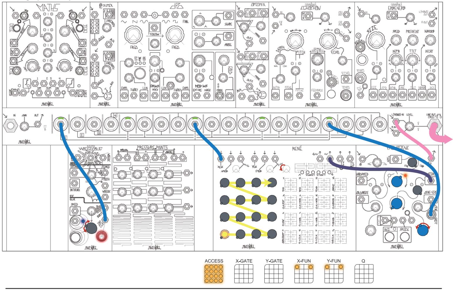
While using the RENE to sequence the playback of GENE's may result in some really amazing loops, that's just the tip of the iceberg! Try migrating to RENE's X-Gate and Y-Gate pages to Program two Gates (i.e. X-Gate and Y-Gate Outputs) that fire as the sequence moves: perfect for creating or Triggering other sounds from within your modular. With X-Gate set as it is below, you should hear the DPO on the downbeat of "1" and "3" of each bar in the sequence. With Y-Gate set as below, you should hear the EP on the downbeat of "2" and "3" of each bar in the sequence. Adjust X and Y-Gate settings to taste.
If you haven't moved the Vari-Speed Panel Control from where it was set when you originally recorded, you may easily re-record a new loop by unpatching from the PHONOGENE's Play and SLIDE CV Inputs, rotating the Sound On Sound Panel Control back to LIVE. Once the new loop is recorded, re-patch the cables to the Play and SLIDE CV Inputs to build where you left off. As before,
Adding More Sounds:


16 Touch Plates:
To Manually Splice and Trigger and Sample, first record a loop as before. If there is a little too much space before or after the sample, use the Splice button to trim the Start and End points to create a Splice that loops nicely. Next, turn Gene Size and SLIDE fully-clockwise. Slowly rotate Slide counter-clockwise through the entire Range, along the way, [Pressing] Splice at the first loud transient in a series of tiny Genes. This process is demonstrated here:
(https://www.youtube.com/watch?v=zSPeaVAn0ds).
Now, with Organize counter-clockwise and its associated Attenuator full clockwise, patch PRESSURE POINTS Tuned Voltages Output Y to the Organize CV Input, and the CH.4 Common Gate Output to the PHONOGENE's Play Input. Each Touch Plate may now be set to select and Trigger a new Splice, using the associated Row Y Tuned Voltage Panel Controls. Chain up to four PRESSURE POINTS to select up to (16) different Splices within the original sample.

Using BRAINS to Sequence Splices:


Similar to the patch above, this patch uses the BRAINS to sequence playback.
Note: PRESSURE POINTS Row Y Tuned Voltage has a Range of 0-5V, which is what the ORGANIZE CV INput expects.
Using BRAINS to Sequence GENES:


This patch is very similar to the RENE patch from page 24, which uses GENES to separate and sequence each sound in the loop.
Note: PRESSURE POINTS Row X Tuned Voltage has a range of 0-8V, which is what the SLIDE CV INput expects.
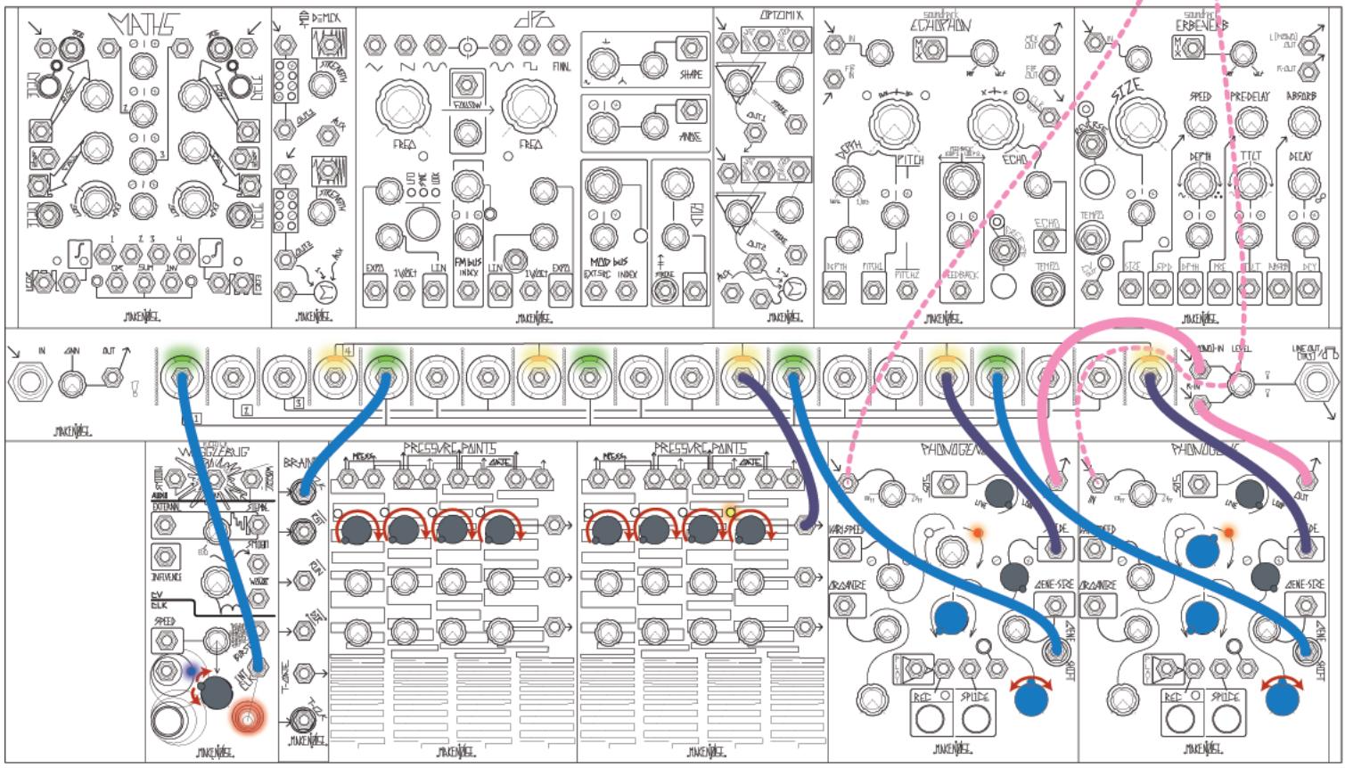
Feel like you're getting the hang of it? Try stereo sampling using (2) PHONOGENES in conjunction with the previously-discussed techniques: one for the Left channel of audio, one for the Right channel. Rather than attempting to [PRESS] the Record or PLAY Button at the same time on both PHONOGENES, MULT the GATE OUTput from PRESSURE POINTS to the associated INput(s). In order to select the same GENE's on both units (keeping the L and R tracks synchronized), MULT the CV signal to both associated CV INputs.



- PHONOGENE
- FC
- CE
- ABOUT THIS MANUAL
- ELECTROCUTION HAZARD
- PERPECTIVE
- PHONOGENE PANEL CONTROLS
- ERASE ROUTINE
- SIGNAL TO BE CAPTURED
- RECORDING TIME AND QUALITY
- SIGNAL OUT
- SOUND ON SOUND
- SPLICING
- RE-ORGANIZING SPLICES
- SPEED VARIATION, DIRECTION VARIATION
- SETTING SIZE OF GENES
- TRAVERSING SOUND ON A GENETIC LEVEL IN A NONLINEAR WAY
- SYNCHRONIZING THE PHONOGENE
- NOTE: ALL NEW PHONOGENES SHIPPED AFTER JULY 2013 ARE LOADED WITH FIRMWARE V.372H
- TO ENTER BROKEN ECHO MODE
- RECYCLER: RECORD
- SOUND REPLACER
- SLIDING PHONOGENE
- FOR THE INFINITE BENEFIT OF MR. KITE
- REGENERATIVE RECORD
- ECHOPHON
- IT'S GONNA COME OUT
- GENETIC MOSAIC
- THESE...ARE...THE BREAKS
- (HTTPS://YOUTU.BE/ZSPEAVAN0DS?T=15)
- TOUCH PLATES
Brand : Make Noise
Model : Phonogene
Category : Audio Equipment