aCA7 - Preamplifier Cyrus Audio - Free user manual and instructions
Find the device manual for free aCA7 Cyrus Audio in PDF.


User questions about aCA7 Cyrus Audio
0 question about this device. Answer the ones you know or ask your own.
Ask a new question about this device
Download the instructions for your Preamplifier in PDF format for free! Find your manual aCA7 - Cyrus Audio and take your electronic device back in hand. On this page are published all the documents necessary for the use of your device. aCA7 by Cyrus Audio.
USER MANUAL aCA7 Cyrus Audio
User Instructions Cyrus aCA7
Congratulations on the purchase of your Cyrus aCA7 pre-amplifier. This piece of equipment is a precision manufactured state-of-art product, constructed to the highest standards and specifications. This manual contains installation and operating instructions to enable the user to connect and operate this pre-amplifier correctly, thus ensuring the greatest satisfaction and long term use.
This instruction manual is divided into the following sections.
Cautions....2
Installation....4
Operation....7
Remote Control....10
Additional Information......12
Trouble Shooting....15
Remote Control of a Cyrus System ....17
Specifications....19
Guarantee....20
To enable you to make full use of the comprehensive facilities of this pre-amplifier we suggest that you read these sections which will explain the fundamental operations of the unit.
UNPACKING
Always follow the instruction handbook and retain it in a safe place for future reference.
Before proceeding with installing the Cyrus aCA7, ensure that the following items are included in the accessory box:
• Instruction Manual
- Power Cable
• Audio Commander Handset
• 2 phono cables for MC-Bus connections
- Guarantee Card
After removing these items, please retain the packing for future use.
CAUTION
POLARISED CONNECTOR (115V PRODUCTS ONLY) CONNECTOR POLARISE (PRODUITS 115V SEULEMENT)
To prevent electrical shock, match wide blade of plug to wide slot and fully insert
Attention: Pour éviter les chocs électriques, introduire la lame la plus large de la fiche dans la borne correspondante de la prise et pousser jusqu'au fond.
SUPPLY VOLTAGE
Your Cyrus aCA7 pre-amplifier is set to operate from the mains supply voltage marked on the rear of the unit. Ensure this voltage is the same as your mains supply, i.e.
230V Products
Voltage Range 220V-240V
115V Products
Voltage Range 110V-120V
Consult your Mission distributor to arrange for conversion of your Cyrus aCA7 if you move to an area with a different mains voltage.
LOCATION
Install the Cyrus aCA7 in a well ventilated location where it will not be exposed to high temperature or humidity.
Avoid installing the Cyrus aCA7 in a location which is exposed to direct rays of the sun, or near hot appliances or radiators. Placing the unit on heat-generating sources or installing it in damp or dusty conditions will affect performance and may result in malfunction or accident.
POSITIONING THE UNIT
The Cyrus aCA7 may be positioned either free standing or alongside another piece of audio equipment. Never stand the Cyrus aCA7 under another unit. This may adversely affect the cooling of the Cyrus aCA7. Never place the unit on any surface which may hamper normal ventilation.
PRECAUTIONS REGARDING INSTALLATION
It is important not to allow any liquid or foreign object fall into this unit. When routing the power cord avoid running it over or near sharp objects. Do not stand objects on the power cord.
If the Cyrus aCA7 is not to be used for a long period of time, unplug the unit from the mains power supply.
This unit contains no user serviceable parts.
Never remove any panels from the unit or attempt to service the unit. In the unlikely event of failure, please refer to qualified service personnel.
Important Note for UK Customers
The mains lead of this unit is fitted with a UK 13A Plug. Do NOT disassemble this plug. If for any reason you remove the plug, dispose of it safely and do not attempt to re-use it.
The wires in the mains lead are coloured in accordance with the following code: Blue - neutral, Brown - live.
If these colours do not correspond with the coloured markings identifying the terminals on your new mains plug:
Connect the Blue wire to the terminal which is marked with the letter N or coloured Black.
Connect the Brown wire to the terminal which is marked with the letter L or coloured Red.
Ensure that your equipment is connected correctly. If in doubt, consult a qualified electrician.

-
Headphone Output
-
MC-BUS System Connection
-
Pre-amplifier Output 2
-
Pre-amplifier Output 1
-
Tape Output 2
-
Tape Output 1
-
Tape Input 2
-
Tape Input 1
-
Auxiliary Input 2
Fig. 1 Cyrus aCA7 (rear view)
-
Auxiliary Input 1
-
Audio Visual Input
-
Tuner Input
-
CD Input
-
PSX-R Connection
-
Power Inlet
-
Mains Fuse
-
Balanced Output (L. Channel)
-
Balanced Output (R. Channel)
CONNECTING POWER TO THE UNIT
Refer to figure 1, rear panel drawing on page 4.
Plug the moulded IEC connector of the supplied mains lead into the power inlet on the rear of the unit.
The mains fuse is located on the rear panel. It must only be replaced with the following types:
U.K. / Europe - 230V
T200mA/20mm
N. America / Far East - 115V
T400mA/20mm
In the U.K., the Cyrus aCA7 power lead is supplied fitted with a mains plug. If the plug fuse should need replacing ensure that it is replaced only with a 3 Amp Fuse.
CONNECTING A CYRUS PSX-R
If a Cyrus PSX-R is to be used with the Cyrus aCA7, connect the umbilical cord of the PSX-R to the 5-pin Cannon input socket of the Cyrus aCA7. When correctly fitted the connector will latch into place in the socket.
No other connections or internal modifications to the Cyrus aCA7 are needed for PSX-R connection.
Note: Please ensure that the Cyrus aCA7 and the PSX-R are unplugged from the mains before connecting the units.
When a PSX-R is in use, both the Cyrus PSX-R power supply and the Cyrus aCA7 will require mains power. For more details refer to the Cyrus PSX-R Instruction Manual.
CONNECTING SOURCE INPUTS
Connect a quality RCA phono cable between each system component and the appropriate rear panel socket. Observe the colour coding of the phono cable for left and right channel identification. The standard convention is– Right Channel RED, Left Channel WHITE or BLACK.
The Cyrus aCA7 provides connections for a CD Player – CD ⑬, a tuner – TU ⑫, an Audio Visual processor– AV ⑪, two auxiliary inputs– AUX1 ⑩ and AUX2 ⑨ and two tape decks TP1 ⑧ and TP2 ⑦.
The AUX inputs can be used for connection of a wide variety of products such as a second CD player, an electronic keyboard, etc.
Always check the technical specification of source products before connecting them to your Cyrus aCA7. Consult your dealer if in doubt.
CONNECTING A TURNTABLE
The Cyrus aCA7 is a line level pre-amplifier. To play a turntable through your unit you require an external phono pre-amplifier. The Cyrus aEQ7 phono pre-amplifier is available from Cyrus which fully integrates with the Cyrus aCA7 and has comprehensive facilities for both moving coil and moving magnet cartridges.
CONNECTING A TAPE RECORDER
Two tape decks may be connected to the Cyrus aCA7.
Tape 1 is suitable for all tape decks and other recording units but does not feature off-tape monitoring.
Tape 2 has a conventional tape loop with full monitoring facilities suitable for all tape decks including three-head models with off-tape monitoring.
To connect a tape recorder:
Firstly, connect a phono cable from the Output or Playback sockets of the tape recorder to the required Tape Input sockets- ⑦ or ⑧ of the Cyrus aCA7. Now connect a second phono cable from the Input or Record sockets of the tape recorder to the Tape Output sockets ⑤ or ⑥ of the Cyrus aCA7.
A three head tape recorder should be connected to the Tape 2 sockets. For other units we suggest Tape 1.
For a fuller treatment of recording topics refer to Additional Information on page 12. Refer to your recorder handbook if you are in any doubt.
CONNECTING HEADPHONES
The HEADPHONES socket ① is a standard 1/4 " stereo jack socket for connection to a pair of conventional headphones. It should not be used with Electrostatic units.
CONNECTING A POWER AMPLIFIER
The Cyrus aCA7 must be connected to a power amplifier in order to drive the system loudspeakers. RCA phono and Balanced XLR connection systems are provided, the appropriate connection depending on each individual installation. Where the Cyrus aCA7 is placed close to the power amplifier we recommend using the RCA phono connections. If the power amplifier is some distance from the Cyrus aCA7 (e.g. beside the loudspeakers) balanced XLR connections may give improved performance.
Connecting RCA phono cables to a power amplifier
Two pairs of RCA output sockets (PRE OUT) ③ and ④ are available on the Cyrus aCA7. Connect a quality phono cable from one PRE OUT pair to the left and right inputs of the power amplifier. The other pair may be used for bi-amping, etc. – see Additional Information on Page 12.
Connecting Balanced XLR cables to a power amplifier
Connect a 3 pin XLR cable between each channel of the Cyrus aCA7 balanced outputs ⑰ and ⑱ and the corresponding XLR input of the power amplifier.
Note: If RCA and XLR outputs are simultaneously used to power two stereo amplifiers (or two monobloc pairs), they must all be Cyrus units. Never connect RCA and XLR cables to alternate channels of the same amplifier.

- Mute
- Standby Switch
- Standby Light
- Headphones Switch
- Remote Eye
- Level Control
Fig. 2 Cyrus aCA7 (front view)
- Tape 2
- Tape 1
- Auxiliary 2
- Auxiliary 1
- AV (Video)
- Tuner
- CD
POWER CONTROL
Refer to figure 2, front panel drawing on page 7.
The STANDBY key ② is used for power control. The Standby light ③ will show Red when the Cyrus aCA7 is off and Green when operating. Selecting any input source will also switch on the Cyrus aCA7.
SELECTING AN INPUT
The INPUT SELECT keys ⑨ - ⑬ switch between selected input sources. When an input key is selected, the red indicator above the key will turn on.
TAPE PLAYBACK
To replay a tape source connected to the TAPE 1 sockets press the TP1 key ⑧.
To replay a tape source connected to the TAPE 2 sockets press the TP2 key ⑦. The indicator above the TP2 key will now light in addition to the selected source. A further press of the TP2 key will return to the current selected source.
Additionally, the Tape 2 input provides an off-tape monitor facility. If your tape deck is equipped with three-heads, selecting the TP2 key enables a recording to be monitored, whilst recording.
TAPE RECORDING
The signal from the selected source is sent to Tape Recorders connected to both TAPE 1 and TAPE 2 circuits automatically. Tape recordings may therefore be made from the selected source to either, or both of the Tape Recorders. In addition, tape copying is possible by playing the tape recorder connected to the TAPE 1 input and recording to TAPE 2 (See Page 12 for a fuller treatment of tape recording).
VOLUME CONTROL
The LEVEL CONTROL ⑥ of the Cyrus aCA7 performs the dual functions of volume and balance. The light ring display around the rotary knob indicates either volume or balance depending on the current mode of operation.
The Level Control of the Cyrus aCA7 controls the volume level in 1dB steps. The light ring around the knob is calibrated to show the current loudness level. When the volume is at minimum the first indicator on the light ring will be RED. As the volume increases, a GREEN light will move clockwise around the ring.
BALANCE CONTROL
The Cyrus aCA7 is equipped with a BALANCE key on the remote handset. Page 11 has the full procedure for adjusting channel balance.
MUTE
Pressing the MUTE Key ① will fade the volume to minimum. The RED minimum level indicator will light in addition to the existing GREEN light to show that the output is muted. Moving the volume knob or pressing the Mute key fades the signal up to the original setting.
If the level was set very high when the Cyrus aCA7 was muted, when unmuted it will return at a safe lower setting.
USING HEADPHONES
The HEADPHONES key ④ on the Cyrus aCA7 front panel is a special form of Mute switch. When you press the HEADPHONES key, the main output from the Cyrus aCA7 to the power amplifier is muted so that you can listen to the headphones without the speakers. To restore loudspeaker operation, press this key again.
When Headphones operation is selected, the MUTE light at the bottom of the light ring will glow Orange
Note: The HEADPHONES key is operational only when headphones are connected.
Caution: If you have been listening to headphones at high volume, be sure to turn the level down before you switch to normal loudspeaker operation.
Volume and Mute Indications

Normal listening level Orange mute- ‘phones Red mute- Full mute

Normal listening level Normal operation
The Cyrus aCA7 always reverts to its last setting when the MUTE key is toggled. If, when listening to headphones (Orange mute on) you press the MUTE key, the Mute light will change to Red and the full system will mute. If you press the Mute key again the Orange mute light will return.
Standby
If you set the Cyrus aCA7 to Standby when you are in Headphone mode, when you next bring the unit out of Standby it will revert to Headphone operation.
If you unplug the headphones after you have set Standby, when you next switch on the Cyrus aCA7, loudspeaker operation will be restored.
Refer to Additional Information on Page 12 for more details.
THE CYRUS AUDIO COMMANDER
The remote control handset of the Cyrus aCA7 provides unified control over a wide range of Cyrus separates.

- Volume Up/Down
- Aux 2 Input
- Aux 1 Input
- CD Input
- Tuner Input
- Audio Visual Input
- System ON
- STANDBY
- Tape Inputs/Monitor
- Mute
- Balance
REMOTE OPERATION OF THE CYRUS aCA7
The top three rows of keys on the handset replicate the front panel of the Cyrus aCA7. Other keys control associated Cyrus units.
Inserting the batteries
Remove the battery compartment cover on the rear of the handset and insert the four supplied AAA batteries in the spaces provided observing the polarity markings on the batteries and the handset. Replace the compartment cover.
Standby Control
Press the ON key ⑦ to bring the Cyrus aCA7 out of Standby (and other Cyrus units connected via MC-Bus).
Press the OFF key ⑧ to return the Cyrus aCA7 to Standby. Selecting an input will also bring the unit out of Standby.
Selecting a Source Input
Press any source key ② - ⑥ to select and listen to the appropriate source.
Operating the Tape key
The TP key ⑨ controls both tape inputs.
To select Tape 1 give a short press on the TP key ⑨.
To select Tape 2 give a long press ( 1/2 sec) on the TP key.
When Tape 2 is selected, a single long press of the TP key will deselect Tape 2.
(To deselect Tape 1, press another source key)
Level and Balance Controls
The - ∠ + keys ① are used to adjust both volume level and channel balance.
Volume
Press + to increase the volume level.
Press - △ to decrease the volume level.
Balance
Pressing the △▲ key ⑪ changes the mode of the Level Control to that of Left/Right Balance.
When Balance mode is selected, the light ring around the level knob will change function to work in "reverse video" with the unlit section indicating the position of L-R balance. In this mode, you can control the L-R balance by up to +/-4dB as well as switching one channel off completely when the balance is set to an extreme position.
Typical Balance indications are shown below.
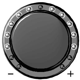
Channel Balance Normal

Channel Balance R-CH +2dB

Channel Balance L-CH only
To adjust Channel Balance:
Press the △▲ key ⑪ to select Balance mode.
Press △ + to move the channel balance to the Right.
Press - △ to move the channel balance to the Left.
Press the △▲ key again to restore normal Volume mode.
If you leave the Cyrus aCA7 set to Balance, after 5 seconds of inactivity the mode automatically reverts to indicate volume level.
As an alternative to using the handset keys to adjust the balance, you may use the △▲ key to select balance mode and then adjust the balance using the Level Control on the front panel.
Mute
Pressing the MUTE key ⑩ fades the main volume to zero.
Pressing the MUTE key again restores the volume to the level it was at prior to selecting Mute (unless the volume was set very high in which case the Cyrus aCA7 will restore at a safe lower level of -15dB).
You cannot select or deselect headphones via the handset.
SYSTEM OPERATION WITH THE COMMANDER
When a Cyrus CD player, FM7 tuner and suitable ancillary units are connected to the Cyrus aCA7, integrated system operation is possible using the Remote Commander handset (see page 17 for details).
KNOW YOUR CYRUS aCA7
Power
- When first powered from the mains, the Cyrus aCA7 will run a self-test and then revert to Standby. When first switched on from standby the CD input is selected and the volume is set to minimum.
- When the Cyrus aCA7 is set to standby after a period of use, Input selection and Volume/Balance settings are retained. If the unit is put in standby while set to a very high volume level, the Cyrus aCA7 will power on at a safe level of -15dB when next switched on.
• These conditions also apply to the Mute functions. - When switched to Standby, the audio circuits of the Cyrus aCA7 are shut down for optimal safety.
Volume and Balance
- The volume control system of your Cyrus aCA7 is a musically transparent precision 1dB - step attenuator. This design is precise to limits of +/-0.1dB throughout all 86 steps of attenuation available.
- As the volume setting of your Cyrus aCA7 is achieved independently for Left and Right channels, channel balance can be controlled with precision by applying an offset to either channel. Channel balance is maintained to +/- 0.2dB across the entire range.
Bi-amping / Tri-amping
- In addition to the balanced output, there are two sets of RCA sockets on the Cyrus aCA7. This enables you easily to connect additional power amplifier blocks to upgrade your loudspeaker system for Bi-amping or Tri-amping. Stereo and Monobloc amplifiers are available from Cyrus for this application.
Powering each drive unit separately increases maximum output and dynamic range and, with each amplifier driving a limited frequency band, clarity imaging and transparency are all greatly improved.
NOTES ON RECORDING
Unless you own a 3 head tape deck, your recording unit whether MD, DAT or CD-R will not have true playback monitoring so you may use Tape 1 or Tape 2. If you have two recording units, say MD and cassette deck, we suggest you connect the MD player to Tape 1 and the cassette deck to Tape 2 for greater flexibility.
Note: You cannot record from Tape 2 to Tape 1.
Many high quality VCRs produce acceptable audio recordings and their long tape times are useful. Even without an AV processor, by using your VCR in conjunction with the Cyrus aCA7 the audio component of your TV and Video programmes will be hugely improved. Consult your dealer for advice if in doubt.
PROGRAMMABLE INPUT SENSITIVITY
In all audio systems, there will be audible changes in volume when switching from one source to another because source component output levels vary. To compensate for this, each input of the Cyrus aCA7 can be matched in level with reference to the CD input.
To alter an input level:-
- Select CD input on the Cyrus aCA7 and set the volume control to a comfortable listening level.
- Select the required input (tuner, etc.) on the Cyrus aCA7 front panel. Keep the input key pressed and the display will change to indicate input offset (see diagrams).
- Adjust the level control to give the same audible volume as the CD player. The display indicates the offset applied.
- Store the offset by pressing the input key again.
To restore the factory settings, follow steps 2 to 4, setting the display to 'zero offset' - see the diagram below

This display shows the factory setting for the Cyrus aCA7.
It indicates that the selected input has the same sensitivity as the CD input (zero offset display).

This display shows that the selected input (e.g. tuner) has been programmed to be 2dB more sensitive than the CD input. This will increase the sensitivity of the tuner input to give equal volume levels from CD and tuner.

This display shows that the selected input (e.g. AV) has been programmed to be 4dB more sensitive than the CD input. This will increase the sensitivity of the AV input to give equal volume levels from CD and the AV unit.
MC-BUS AUTO-CALIBRATION - AV-MASTER
When a Cyrus AV master is wired into the MC-BUS loop, precise volume calibration will take place when the AV input is selected on the Cyrus aCA7. Refer to your Cyrus AV-master handbook for further details.
PSX-R REGULATED POWER SUPPLY -
The PSX-R is a highly regulated DC power supply. Its use will upgrade the sonic performance of your Cyrus aCA7. No adjustments are necessary when connecting the Cyrus PSX-R to the Cyrus aCA7 - full connection instructions can be found on page 5.
MC-BUS SYSTEM CONNECTION
The MC-Bus system (see drawing on page 4) can provide unified power control of a complete Cyrus system from your Cyrus aCA7. MC-Bus connections are wired as a 'loop' with single RCA phono interconnects. The diagram below shows a typical Cyrus system of Cyrus CD Player, Cyrus FM7, Cyrus aCA7 and Cyrus Power Amplifier with the MC-Bus loop connected. Connect the first cable between the MC-Bus output ② of the Cyrus aCA7 and the MC-Bus input of the next Cyrus component. Continue to wire each MC-Bus output to the next input, returning to the Cyrus aCA7 input to complete the loop.
OPERATION WITH MC-BUS CONNECTED
When MC-BUS connections have been made it is possible to control the power function of the entire system from the Cyrus aCA7.
For example, if you select 'CD' from either the Cyrus aCA7 front panel or the Audio Commander, you will switch on the Cyrus aCA7, the Cyrus CD player and any connected Cyrus Power amplifiers.
When the Cyrus aCA7 is set to Standby, all system components will also switch off.

TROUBLESHOOTING GUIDE
If you suspect your Cyrus aCA7 is not operating to specification, check carefully all connections using the installation section of this handbook. If problems persist, the checklists below may help.
Ensure the power to all units is switched off before altering any connections and only switch the power on again when the new connections are fully made.
No Sound from either Speaker
- Check that the pre-amplifier and the power amplifier is on. The standby light should be green.
- Check that the pre-amplifier responds to different front panel commands.
- Check that the MUTE light on the volume control light ring is completely "OFF" -( see Page 9).
- Check that the relevant programme source is selected and is working (e.g. the CD Player is playing).
- Check that the Tape Monitor (Tape 2) is not selected inadvertently.
- Check that the headphones work normally.
- Check both the input and speaker connections to the power amplifier.
No Sound from one Speaker
- Check the Balance Control is not set to extreme limits.
- If your loudspeakers are fitted with protection fuses, check that the fuse is intact.
- Check interconnect cable integrity on the rear panel and at source. Try another interconnect cable.
- Check the interconnect cable integrity between the Cyrus aCA7 and the power amplifier.
- Check the speaker cable integrity of the missing channel at the power amplifier and loudspeaker.
If the problem persists:
- Change the programme source using the suspected interconnect cable and check that the problem still exists. If the fault clears the original source is at fault.
- Interchange the left and right connections of the interconnect cable at SOURCE. If the missing channel switches over then there is a problem in one channel of the source or the interconnect.
Note: Restore the system to its original configuration after completion of the above series of tests.
Spurious Sounds from the Loudspeakers
If you experience strange or unnatural noises from your system proceed as follows:
- Select another source to ensure that this is not a common problem. If the problem remains, switch the Cyrus aCA7 off at the mains or disconnect the mains plug. Replace the mains plug after a few seconds and restore power to the Cyrus aCA7. If the fault persists or you are in any doubt, consult your dealer.
- If the problem is limited to a single source, check the integrity of the interconnection to the source and in the case of a phono turntable, check that the phono ground wire is secured at the rear panel of the associated cartridge pre-amplifier.
FAULT INDICATION SYSTEM
The Cyrus aCA7 has a fault indication system to help you to diagnose the cause of a problem. Fault indications are presented by the Standby light on the front panel.
- Flashing RED
There is a problem with the internal power supply of the Cyrus aCA7. Switch the unit off at the mains and switch on again after a few seconds. If the indicator still flashes, return the unit to your dealer for attention.
Fault Indications involving PSX-R connections
- Flashing RED
A PSX-R that is switched off is connected to the Cyrus aCA7.
A PSX-R has been disconnected while the Cyrus aCA7 is operating.
There is a fault with the internal power supply of the Cyrus aCA7.
- Flashing Green
A PSX-R has been connected while the Cyrus aCA7 is in normal operating mode.
In all the above cases you should switch all units off, fully disconnect the PSX-R, and switch on the aCA7 again.
If normal operation resumes, switch the Cyrus aCA7 off and re-connect the PSX-R following the instructions on Page 5 of this manual. The system should now work normally.
If the fault indications persist, return the suspect unit to your dealer for attention.
REMOTE POWER CONTROL
Your Cyrus aCA7 and its associated power amplifier/s may be turned on by selecting any Source Key ① on the handset. Pressing the TU or the CD Key will also switch the relevant Cyrus unit on. To switch the system power off from a remote position, press the STANDBY Key ③.

- Source Keypad
- System On
- System Standby
- Pause (CDs)
- Play (CDs)
- Open/Close (CDs)
- Next/Previous (CDs & FM7)
- Seek Up/Down (CDs & FM7)
- Memory Store (CDs & FM7)
- Number Keypad (CDs & FM7)
- Repeat (dAD1)
Phase Invert (Other CDs) - Time Display (CDs)
- Mono (FM7)
- Display On/Off (CDs & FM7)
REMOTE CONTROL OF THE CYRUS FM7
Auto Tuning: Pressing the SEEK UP/DOWN key ⑧ will cause the FM7 to scan up or down the band, stopping when a station with usable signal strength is detected.
Storing a Preset: Tune in a station and press the Memory STORE key ⑨. The preset digits on the display will flash prompting you to enter a two-digit preset location number. For numbers under 9 the digit must be preceded by a zero. You may store 29 preset locations from the handset.
Recalling a Preset: Enter a two-digit number from 1 to 29 via the NUMBER keypad ⑩. Location numbers 3 to 9 can be accessed by a single digit entry.
Scanning Station Presets: Pressing the NEXT or PREVIOUS keys ⑦ allows you to scan all the stations that have been preset on the FM7. The preset station numbers appear on the tuner display. (Some FM7s may not have this feature: consult your dealer for details of an upgrade).
Mono Operation: To enable mono, press the MONO key ⑬. The mono symbol ■ will show in the FM7's display. Selecting mono will reduce background noise on weak stereo transmissions Press the key again to restore Stereo.
Display: The DISPLAY key ⑭ toggles the display of the FM7 off and on. Switching off the display eliminates its digital traffic and improves the FM7's performance.
REMOTE CONTROL OF CYRUS CD PLAYERS
Operating the Disc Tray: If the disc is stationary, one touch of the STOP/OPEN key ⑥ will open the tray. A second press will close the tray.
When a disc is playing, pressing STOP once will stop the disc: pressing STOP twice will stop the disc and open the tray. A long continued depression of the STOP key will both stop the disc and open the CD loading tray.
Playing a Disc: To play a disc, press the PLAY key ⑫. Play will start from track 1, or from the first track of a stored program sequence.
Note: Discmaster, dAD7 – If you press PLAY whilst a disc is playing, the player will revert to the start of the current track and replay from there.
Pause: Press the PAUSE key ④ to pause the track being played. Press the PLAY key ⑤ to resume playing the disc.
Search: Use the SEEK UP/DOWN key ⑧. Press the SEEK UP key to engage Forward Search. Press the SEEK DOWN key to engage Reverse Search.
Previous/Next Track Selection: Pressing the NEXT or PREVIOUS keys ⑧ allows you to advance or regress successively through all the tracks on the CD. Track indications appear on the CD player display.
Display: The DISPLAY key ⑭ toggles the display on/off.
Time Display key ⑫. This toggles the display between:
Elapsed Time ( ⇔ ), - the time elapsed from the beginning of the current track, and
Remaining Time ( ), - the time remaining to the end of the disc or a program, if stored.
Direct Access Numeric Keypad: Press a number key ⑩ to select and play a track. The track number appears on the display. If there are more than ten tracks the CD player will briefly wait for a second digit where appropriate.
Program Storage: To store a program of up to 20 tracks:
dAD3, dAD1 - Select a track using the number keypad or the NEXT/PREVIOUS keys and then press the Memory STORE key ⑦. The display confirms memory storage.
Discmaster, dAD7 – Select the desired track using the NEXT/PREVIOUS keys and then press the Memory STORE key ⑦. The display confirms memory storage
When a program is stored, the keypad will enable access only to tracks included in the program memory.
Phase Reversal - Cyrus dAD3, dAD7, Discmaster: Pressing the key ⑪ reverses the phase of both channels by 180° . The phase reverse symbol ■ will show in the display. Left and right channel balance is unaffected.
Press the key again to restore normal phase.
Repeat - Cyrus dAD1: Pressing the key ⑪ enables continuous play of a CD or a program sequence.
AUDIO PERFORMANCE
Input Sensitivity ....200mV
Input Impedance....50kΩ
Volume Control Accuracy ....+/-0.1dB
0dB to -86dB
Channel Balance....+/-0.2dB
0dB to -86dB
Output Level & Output Impedance
RCA Line 381mV/47Ω
XLR Balanced 775mV/100Ω
Headphones.... 4.2V/120Ω
Frequency Response (-3dB) 1Hz, 100kHz
Signal to Noise Ratio 107dBA
('A' WTD Ref 500mV I/P)
THD+N (20-20kHz) ....<0.005%
POWER SUPPLY
Voltage
See the plate attached to the rear of unit
Power Consumption
Standby 2W
Operational 9W
Safety Compliance
Compliant to the requirements of EN 60065
EMC Compliance
Compliant to EN55013 & EN55022 ...... Europe
ENCLOSURE
Dimensions (WxHxD)....215 x 75 x 365 mm
Weight.... 3.1Kg.
Material......Die cast chassis
The company reserves the right to change this specification without prior notice.
Iss.01-9804 File:7TEN8407.WIM
PRE-AMPLIFIER MAINTENANCE
There are no user serviceable parts in the Cyrus aCA7 so do not remove any of the panels. After disconnecting the mains power supply, the cabinet may be cleaned using a slightly moistened chamois leather. DO NOT use cleaning agents containing alcohol, spirits, ammonia or abrasives.
THE MISSION/CYRUS GROUP MANUFACTURES
- Compact Disc Players
• D-to-A Converters - Pre-amplifiers
• Power amplifiers
• Integrated amplifiers
• Regulated Audio Power Supplies - Radio Tuners
• Surround Sound Decoders
• Multi-Room Audio Controllers - Loudspeakers
- Subwoofers
- Loudspeaker Stands
- Loudspeaker Cables
• Automotive Loudspeakers
• Automotive Amplifiers
GUARANTEE
This guarantee only becomes effective if the guarantee card enclosed is completed by the Dealer and the purchaser and returned to MISSION or Distributor within 8 days of purchase.
This guarantee excludes:
i) All damage caused through accident, misuse, wear and tear, neglect or through incorrect installation, adjustment or repair by unauthorised personnel.
ii) Liability for damage or loss occurring in transit to or from the purchaser.
Claims under this guarantee should be made through the Dealer from whom the equipment was purchased or if not convenient, through another authorised MISSION/CYRUS dealer.
MISSION shall not be liable for consequential damage, loss or injury, arising from or in conjunction with this equipment.
The cost of return carriage shall be borne by the purchaser.
This guarantee is personal to the original Purchaser and is not transferable.
If equipment is found on examination to comply with the published specification, MISSION reserves the right to make a charge for examination and for return carriage.
No Dealer or Distributor may vary the terms of this guarantee.
Any unauthorised servicing will result in loss of guarantee.
We strongly recommend that you retain the sales receipt for your CYRUS equipment in case of any warranty claim.
The above conditions do not affect your statutory rights.

- USER INSTRUCTIONS CYRUS ACA
- UNPACKING
- CAUTION
- SUPPLY VOLTAGE
- LOCATION
- POSITIONING THE UNIT
- PRECAUTIONS REGARDING INSTALLATION
- IMPORTANT NOTE FOR UK CUSTOMERS
- CONNECTING POWER TO THE UNIT
- CONNECTING A CYRUS PSX-R
- CONNECTING SOURCE INPUTS
- CONNECTING A TURNTABLE
- CONNECTING A TAPE RECORDER
- TO CONNECT A TAPE RECORDER
- CONNECTING HEADPHONES
- CONNECTING A POWER AMPLIFIER
- CONNECTING RCA PHONO CABLES TO A POWER AMPLIFIER
- CONNECTING BALANCED XLR CABLES TO A POWER AMPLIFIER
- POWER CONTROL
- SELECTING AN INPUT
- TAPE PLAYBACK
- TAPE RECORDING
- VOLUME CONTROL
- BALANCE CONTROL
- MUTE
- USING HEADPHONES
- VOLUME AND MUTE INDICATIONS
- STANDBY
- THE CYRUS AUDIO COMMANDER
- REMOTE OPERATION OF THE CYRUS ACA
- INSERTING THE BATTERIES
- STANDBY CONTROL
- SELECTING A SOURCE INPUT
- OPERATING THE TAPE KEY
- LEVEL AND BALANCE CONTROLS
- VOLUME
- BALANCE
- TO ADJUST CHANNEL BALANCE
- SYSTEM OPERATION WITH THE COMMANDER
- KNOW YOUR CYRUS ACA
- POWER
- VOLUME AND BALANCE
- BI-AMPING / TRI-AMPING
- NOTES ON RECORDING
- PROGRAMMABLE INPUT SENSITIVITY
- MC-BUS AUTO-CALIBRATION - AV-MASTER
- PSX-R REGULATED POWER SUPPLY
- MC-BUS SYSTEM CONNECTION
- OPERATION WITH MC-BUS CONNECTED
- TROUBLESHOOTING GUIDE
- NO SOUND FROM EITHER SPEAKER
- NO SOUND FROM ONE SPEAKER
- IF THE PROBLEM PERSISTS
- SPURIOUS SOUNDS FROM THE LOUDSPEAKERS
- FAULT INDICATION SYSTEM
- FLASHING RED
- FAULT INDICATIONS INVOLVING PSX-R CONNECTIONS
- FLASHING GREEN
- REMOTE POWER CONTROL
- REMOTE CONTROL OF THE CYRUS FM
- REMOTE CONTROL OF CYRUS CD PLAYERS
- AUDIO PERFORMANCE
- POWER SUPPLY
- ENCLOSURE
- PRE-AMPLIFIER MAINTENANCE
- THE MISSION/CYRUS GROUP MANUFACTURES
- GUARANTEE
Brand : Cyrus Audio
Model : aCA7
Category : Preamplifier