AV5 - AV amplifier Cyrus Audio - Free user manual and instructions
Find the device manual for free AV5 Cyrus Audio in PDF.


| Type | Audio-Video Amplifier |
| Brand | Cyrus Audio |
| Model | AV5 |
| Dimensions (W x H x D) | 215 mm x 75 mm x 365 mm |
| Weight | 2.8 kg |
| Power Consumption | 15 W |
| Mains Supply Voltage | 220-240 V AC (230V models) or 110-120 V AC (115V models) |
| Decoding Systems | PCM Stereo, Dolby Pro Logic, Dolby Digital, DTS |
| Analogue Audio Inputs | 3 x line inputs (RCA) |
| Digital Audio Inputs | 6 x digital inputs (optical/coaxial) |
| Audio Outputs | Front, Surround, Centre, Subwoofer, Tape/VCR, Digital out |
| Input Sensitivity (Analogue) | 200 mV |
| Input Impedance (Analogue) | 47 kΩ |
| Signal-to-Noise Ratio | 80 dBA (analogue), 94 dBA (digital) |
| Total Harmonic Distortion + Noise | 0.008% |
| Channel Separation | 99 dB (1 kHz) |
| Calibration | Manual or automatic speaker level and distance setup |
| Remote Control | Included, operates power, volume, input selection, setup |
| Accessories Included | AC cable, remote, 2 AAA batteries, 2 MC-Bus cables, setup microphone with battery |
| Safety & EMC Compliance | EN 60065, EN55013 & EN55020 |
| Cleaning | Unplug from mains; wipe with a damp cloth; no liquid or aerosol cleaners |
| Repairability | No user-serviceable parts; servicing by qualified personnel only |
Frequently Asked Questions - AV5 Cyrus Audio
User questions about AV5 Cyrus Audio
0 question about this device. Answer the ones you know or ask your own.
Ask a new question about this device
Download the instructions for your AV amplifier in PDF format for free! Find your manual AV5 - Cyrus Audio and take your electronic device back in hand. On this page are published all the documents necessary for the use of your device. AV5 by Cyrus Audio.
USER MANUAL AV5 Cyrus Audio
User Instructions Cyrus AV5
Cyrus AV5


IMPORTANT! Read before operating this equipment!
CAUTION: The exclamation mark is to draw your attention to important instructions and safety procedures in this manual.

ATTENTION: The lightning flash warns you of the risk of electrical shock presented by components inside this product. Unauthorised personnel must not open this unit.

WARNING: To reduce the risk of electrical shock do not remove any unit covers or panels. There are no user serviceable parts in this product.
WARNING: To reduce the risk of electric shock, do not expose this equipment to rain or moisture.
HEED WARNINGS: All warnings on the product and in the operating instructions should be adhered to.
READ ALL THE INSTRUCTIONS: All the safety and operating instructions should be read before the product is operated.
RETAIN INSTRUCTIONS: The safety and operating instructions should be retained for future reference.
FOLLOW INSTRUCTIONS: All operating and use instructions should be followed.
CLEANING: Unplug this product from the mains before cleaning. Do not use liquid or aerosol cleaners. Use a damp cloth for cleaning.
WATER AND MOISTURE: Do not use this product near water - for example, near a bath tub, wash bowl, kitchen sink, or laundry tub, in a wet basement; or near a swimming pool and the like. The product must not be exposed to dripping or splashing and no objects filled with liquids, such as vases, shall be placed on the product.
HEAT: The product should be situated away from heat sources such as radiators, stoves, or any other products (including amplifiers) that produce heat.
VENTILATION: Slots and openings in the cabinet are provided for ventilation, to ensure reliable operation of the product and to protect it from overheating and these openings must not be blocked or covered. The openings should never be blocked by placing the product on a bed, sofa, rug or similar surface. This product should not be placed in a built-in installation such as a bookcase or rack unless proper ventilation is provided or the manufacturer's instructions have been adhered to.
OBJECT OR LIQUID ENTRY: Never push objects of any kind into this product through openings as they may touch dangerous voltage points or short-out parts that could result in a fire or electric shock.
ACCESSORIES: Do not place this product on an unstable cart, stand, tripod, bracket, or table. The product may fall, causing serious injury to a child or adult, and serious damage to the product. Use only with a cart, stand, tripod, bracket or table recommended by the manufacturer, or sold with the product. Any mounting of the product should follow the manufacturer's instructions, and should use a mounting accessory recommended by the manufacturer.
ATTACHMENTS: Do not use attachments not recommended by the product manufacturer as they may cause hazards.
MOVING THE PRODUCT: A product and cart combination should be moved with care. Sudden stops, excessive force, and uneven surfaces may cause the product and cart to overturn.

POWER SOURCES: This product should be operated only from the type of power source indicated on the marking label. If you are not sure of the type of power supply to your home, consult your product dealer or local power company. For products intended to operate from battery power, or other sources, refer to the operating instructions.
OVERLOADING: Never overload wall outlets, extension cords, or integral convenience receptacles. This can result in an increased risk of fire or electric shock.
POWER CORD PROTECTION: Power supply cords should be routed so that they are not likely to be walked on or pinched by items placed upon or against them, paying particular attention to cords at plugs, convenience receptacles, and the point where they exit from the product.
NAKED FLAMES: No naked flame sources, such as candles, must be placed on this product.
LIGHTNING: For added protection for this product during a lightning storm, or when it is left unattended or unused for long periods of time, unplug it from the wall outlet and disconnect the antenna or cable system. This will prevent damage to the product due to lightning and power-line surges.
CAUTION! POLARISED CONNECTOR (CANADA and USA):
To prevent electrical shock, match wide blade of plug to wide slot, fully insert. Do not alter or remove this plug if it does not fit your mains power socket. Have a suitable socket installed by a competent electrician.
POWER SUPPLY:
The moulded IEC connector of the AC cord supplied plugs into the power inlet ⑫ on the rear of the unit.
The mains supply requirement for your Cyrus AV5 is marked on a label on the rear panel. Before connecting, check that this voltage is the same as your mains supply.
230V Products: Voltage Range 220V-240V
115V Products: Voltage Range 110V-120V
If you move to an area with a different mains voltage, contact your local Cyrus distributor to have your product converted.
There are no user replaceable fuses in this unit.
NOTE FOR UK CUSTOMERS:
The Cyrus AV5 is supplied with a power cable terminated by a fused 13A mains plug. This plug should not be removed but if it is removed, dispose of it safely and do not re-use it. To connect a new 13A plug, proceed as follows: Connect the brown wire to the terminal marked L or coloured red. Connect the blue wire to the terminal marked N or coloured black. The internal plug fuse should be 3A.
SERVICING:
Do not attempt to service this product yourself as opening or removing covers may expose you to dangerous voltage or other hazards. Refer all servicing to qualified service personnel.
CONDITIONS REQUIRING SERVICE: Unplug this product from the wall outlet and refer servicing to qualified service personnel when:
- When the power supply cord or plug is damaged.
• If liquid has been spilled, or objects have fallen into the product.
• If the product has been exposed to rain or water.
• If the product has been dropped or damaged in any way. - If the product does not operate normally by following the operating instructions. (Adjust only those controls that are covered by the operating instructions. Improper adjustment of other controls may result in damage requiring extensive work by a qualified technician to restore the product to its normal operation).
- When the product exhibits a distinct change in performance.
REPLACEMENT PARTS: When replacement parts are required, be sure the service technician has used replacements specified by the manufacturer or have the same characteristics as the original part. Unauthorised substitutions may result in fire, electric shock, or other hazards.
SAFETY CHECK: Upon completion of any service or repairs to this product, ask the service technician to perform safety checks to determine that the product is in proper operating condition.
Manufactured under license from Dolby Laboratories. "Dolby", "AC-3", "Pro Logic" and the double-D symbol are trademarks of Dolby Laboratories. Confidential Unpublished Works. Copyright 1992 - 1997 Dolby Laboratories, Inc. All rights reserved.
DTS is a registered trademark of Digital Theatre Systems Inc.
LaserDisc is a trademark of Pioneer Electric Corp.
Welcome to the world of Cyrus!
Congratulations on your choice of Cyrus Audio-Visual products. Our state-of-the-art design technology and outstanding quality of manufacture has won countless awards around the world. We are confident that you will derive great pleasure from owning a product from one of the most recognised and respected manufacturers of hi-fi equipment.
Please read these instructions carefully before commencing installation. They provide full guidance to help you install your Cyrus AV5 safely and correctly.
Preparations for Installation
Before installing the AV5 check that the following items are included in the accessory box.
• Warranty Card (with instruction manual)
- AC Mains Cable
- Remote Control Handset
• 2 AAA Batteries
• 2 MC-Bus phono cables
• Auto set-up Mic with battery
After removing these items, please retain the packaging.
Install the AV5 in a well ventilated location away from sources of high temperature, dust or humidity. Never stand the AV5 under another unit or on any surface likely to hamper its cooling or ventilation.
To avoid damage to your system, always ensure that mains power is disconnected from all system components until installation is complete.
Installation
Key to the rear panel drawing (Fig.1)
| 1. | Input 1 Optical | 11. Surround channel outputs |
| 2. | Input 2 Optical | 12. Centre channel outputs |
| 3. | Input 3 Digital | 13. Subwoofer outputs |
| 4. | Input 4 Digital | 14. VCR/tape record outputs |
| 5. | Input 5 Digital | 15. AC mains inlet |
| 6. | Input 6 Digital | 16. Power switch |
| 7. | Input 7 Analogue | 17. MC-Bus connections |
| 8. | Input 8 Analogue | 18. Microphone socket |
| 9. | Input 9 Tape | 19. Digital output |
| 10. | Front channel outputs |
NOTE: When connecting inputs to the AV5, ensure that only digital audio sources are connected to 'Digital' inputs.
Connecting Digital Audio Sources to the AV5
The digital audio inputs of the AV5 are compatible with a number of different digital audio sources. These include-
• Digital Audio output from a CD player
- DVD players (see specifications for DVD technical compatibility details)
• Digital tape/disc recorders
- Digital Radio
• Digital Satellite receivers
Using a suitable Toslink optical or Digital phono interconnect, connect each digital audio source to one of the inputs 1\~6. Make a note of the input number used for each source as the inputs of the AV5 can be renamed at the set-up stage.
Connecting Analogue Audio Sources to the AV5
Analogue Inputs 7-9 are available for the connection of analogue audio sources to the AV5. Inputs 7-9 are intended for use with analogue program sources which include-
• Analogue output from CD/DVD/LaserDisc Players
- Televisions
• Analogue Satellite Receivers
• FM Radio tuners
• Analogue VCRs/Tape recorders
SCART Connectors
Some TVs, Video Recorders and DVD players have 21 pin SCART style connectors for analogue audio and video input/output. These may be connected to the AV5 with a suitable SCART/phono interconnect or adaptor.
Connecting a LaserDisc player to the AV5
The L/R analogue outputs of a LaserDisc player may be connected to an analogue input of the AV5.
If the LaserDisc player is equipped with a Digital Output this may also be connected to one of the Digital Inputs.
The AV5 is not equipped to decode the R.F. AC-3 output of a LaserDisc player. For R.F. AC-3 signals an external demodulator is necessary to convert the AC-3 signal to be compatible with one of the Digital Audio inputs. Your dealer should be able to advise on the choice of a suitable demodulator.
VCR/Tape recording
If VCRs/Tape recorders are connected to one of the analogue inputs, recordings may also be made from the AV5 VCR/Tape Out sockets. Connect a suitable phono interconnect from the Tape Output sockets of the AV5 to the Record inputs of the VCR/Tape Recorder.
NOTE: The Tape output sockets are only active when the AV5 is set to Stereo mode.
Connecting Power amplifiers
External power amplifiers are necessary to drive the system speakers. Both stereo and high power monoblock Cyrus power amplifiers are available to partner the AV5.
With suitable phono interconnects, connect from the Front ⑩, Surround ⑪, and Centre channel ⑫ outputs to the appropriate power amplifiers. The system loudspeakers may then be connected to each power amplifier.
NOTE:- Take care to connect each of the AV5 output channels to the correct power amplifier and loudspeaker.
In normal use, only one of the Centre channel outputs and a single amplifier channel are connected to the Centre channel speaker. Optionally, the stereo Centre channel output option of the AV5 may be used to drive a stereo amplifier to twin centre channel speakers.
Connecting the Front Channels through a Cyrus hi-fi system
The AV5 can be connected to an existing stereo Cyrus hi-fi system, sharing the power amplifiers from the stereo system for the Front Channels. In this case, connect a stereo phono interconnect from the Front Channel outputs of the AV5 to the VI input sockets of the Cyrus stereo integrated amplifier or pre-amplifier. For this system to function correctly both the AV5 and the Cyrus stereo amplifier must be included in an MC-Bus connection loop (see section 'MC-Bus connection').
NOTE: The MC-Bus systems of the Cyrus III and Cyrus Pre amplifiers are not compatible with the AV5 and should not be connected through MC-Bus.
Connecting a Subwoofer
A subwoofer may be connected with a suitable phono interconnect to either of the Subwoofer outputs 13 . Twin outputs are provided for systems which include subwoofers with stereo input connections or for twin subwoofers.
Video Connections
For audio-visual sources (TV, Video recorder, DVD etc.) a separate video connection must be made from each source to a video line input of the TV. Some TVs will offer a choice of video connections. In most systems the S-Video connection will give the best results (where available).
NOTE:- No video connections are made to the AV5.
MC-BUS Connections
Connecting the MC-Bus sockets ⑰ of the AV5 in an MC Bus system provides unified system power control. An MC Bus loop is established by connecting single phono cables from the MC Bus output of one unit to the MC Bus input of another. Complete the loop by returning the MC Bus output of the final component to the MC Bus input of the first. The drawing below shows an example of MC-Bus wiring for a Cyrus AV5 with a CD player and two power amplifiers.
With MC-BUS established the power function of all connected Cyrus components may be controlled from the AV5 front panel or remote control. When power is switched on, components such as power amplifiers will switch on automatically.
When a Cyrus stereo integrated amplifier or pre-amplifier is connected into the MC-BUS loop, setting of the volume calibration level will take place automatically when the VI/AV input is selected at the Cyrus stereo amplifier.

SETTING UP THE AV5
The AV5 is a highly versatile product which can be easily configured to match accurately the requirements of different Home-Theatre systems.
The recommended initial setting up procedure for the AV5 is this-
- Set speaker sizes
- Set input names
- Set the channel balance and positions for the speakers
• Set special modes of operation
Setting up takes place from the remote control using the SET-UP key area ③7.
You can return to normal operation from the set-up sequence at any time by pressing the EXIT key ③5 on the remote control.
Setting speaker sizes
The first step in setting-up the AV5 is to set the sizes of each system speaker using the following key sequence-
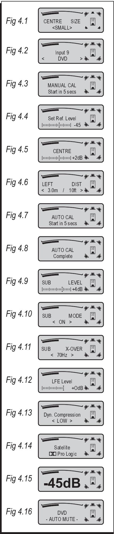
- Press one of the SPEAKER HOT-KEYs ⑰ twice to select speaker size setting. The display will show the chosen speaker name with the current set size (Fig.4.1).
- Choose the correct speaker size with the ADJUST keys 36 . The options are SMALL (for bookshelf or satellite speakers), LARGE (for larger stand mounting or floor-standing speakers), or NONE (if a speaker is not connected in this position).
- Press the next SPEAKER HOT-KEY ③7 to save this setting and move on to set the size of the next speaker, and finally the subwoofer.
The speaker symbols on the display change shape to show the selected sizes for the system speakers (Fig 4.1 shows large front speakers with small centre and surround channel speakers).
NOTE:- If SMALL size is selected for all of the system loudspeakers, a subwoofer must be connected and selected to enable the bass frequencies to be correctly reproduced.
CAUTION:- For the correct reproduction of DTS encoded recordings large speakers are recommended for all sound channels. Speaker size settings are therefore disabled when the AV5 is decoding DTS encoded recordings. If DTS encoded recordings are played through small system speakers caution should be exercised to avoid possible damage through bass overload.
Setting input names
When the AV5 leaves the factory, the input names are set to correspond to the rear panel connections, for example Input 1 will display as- Input 1, IN-1 Digital.
The name of any input may be changed to a choice from the following list-
- LaserDisc, DVD, DVD 1, DVD 2, DVD-A, CD, CD 1, CD 2, SACD, CD-R, Jukebox
- Phono, Deck, Vinyl
- Tuner, Radio, DAB
• TV, Satellite, Satellite 1, Satellite 2, Cable
• Video, VCR, VCR 1, VCR 2, Tape, Cassette, MD, MiniDisc, DAT
• PC, Games, Special, Keyboard, Aux
To change the names of the inputs, first make a list of each input number with your preferred name from the choices above. Where an input is not used, make a note- unused inputs can be switched off.
To rename the current selected input follow this sequence-
-
Press the SET-UP 1 'INPUT' key Ⓤ on the remote control. The display will now show the selected input number on the top row and the current name on the bottom row with brackets (Fig.4.2).
-
Use the ADJUST keys ③ to change the input names on the bottom row of the display until your preferred name appears from the list of available names. The full list of names appears above.
- Now you can choose to exit and save the changes (press the EXIT key ⑲) or to re-name another input (repeat step 1 to select another input then step 2 to re-name it).
Setting speaker channel balance and positions
To ensure the best performance from your multi-channel audio system it is essential to balance all sound channels to reproduce equal sound levels from the system speakers. The AV5 includes two noise set-up options-
- Manual noise adjustment to balance individual speaker volume levels.
- Fully automatic adjustment to balance speaker volume levels and to measure the distance to the speakers.
The automatic system is recommended, particularly for initial adjustment to get the system running.
NOTE:- To allow high volume levels to be reached, high value positive balance settings are reduced at very high settings of the volume control. When this condition occurs, the display will flash the legend 'Balance limiting' briefly. Normal balance settings are restored when the volume setting is reduced.
Manual noise adjustment
Press the SET-UP 2 NOISE key ④ once to start the manual noise sequence. MANUAL CAL will now show on the display and a 5 second count down begins (Fig 4.3). After the count down a noise signal will be heard from the front left speaker. Set the noise to a comfortable level with the ADJUST keys ③. The noise will now cycle around all of the system speakers.
As the noise sequence moves you can compare the sound level from each speaker and make level balance adjustments with the set up ADJUST keys 38 . The display shows the active speaker and a bargraph for balance level (Fig 4.5). If no adjustment is made within 2 seconds the noise will sequence to the next speaker in the system. When adjustment is complete, press the EXIT key 35 .
When noise adjustment is active the top row of the display will show the selected speaker while the bottom row indicates the current balance setting from -10dB to +10dB (Fig 4.5).
Manual distance setting
Before commencing manual distance setting, measure the distance from each of the five main channel speakers to the listening position and make a note of the measurements.
- Press one of the SPEAKER HOT-KEYs ⑲ three times to select speaker distance setting. The display will show the chosen speaker name with the current set distance (Fig.4.6).
- Choose a distance measurement for the chosen speaker from the available options with the ADJUST keys 36 . Distances can be set in the range 0-9.1m (30ft).
- Press the next SPEAKER HOT-KEY to save this setting and move on to set the distance to the next speaker.
Automatic level adjustment and distance setting
NOTE- For automatic setting the microphone must be connected to the rear panel socket ⑯ before starting the process. The battery must be fitted inside the microphone plug before use. Observe the polarity markings when fitting the battery. Remove the battery from the microphone if it is only used occasionally.
- Before commencing the sequence, set up the microphone in the listening position at approximately head height, facing vertically upwards.
- Press the SET-UP 2 NOISE key ④ twice to start the automatic noise sequence. AUTO CAL will show on the display with a 5
second count down (Fig 4.7). Before commencing the AUTO CAL sequence the AV5 will perform a microphone test with a short noise burst. If there is a problem with the microphone or it's connection, the display will show a 'Mic Error' indication. In this case the microphone connection and battery should be checked before restarting the AUTO CAL process.
- Following a successful microphone test the noise signal will be heard at an increasing level from the front left speaker and the setup sequence will start.
The set-up sequence runs in two parts, the first will set the relative volume levels between the loudspeakers, the second will measure the distance from the listener to the speakers and set corresponding delay times. At the end of the sequence the display will show 'Complete' (Fig. 4.8) for 5 seconds before returning to normal operation. The stored settings can be checked, if required by selecting Manual Noise or Distance adjustment.
Factory balance settings
The factory setting for all channels is centre scale when all channels are at equal volume.
NOTE:- The noise sequence is also helpful to check that all channels have been connected correctly. When correctly connected the noise should start with the left front channel and circulate clockwise.
Setting up the sub-woofer
For correct reproduction of the deep bass content of multi-channel home-theatre programs a sub-woofer is recommended for AV5 systems.
Deep bass information is fed to the sub-woofer in two ways-
- From the separate LFE low frequency effects channel of digitally encoded programs.
- When one or more of the system speakers are set to 'small size' the bass from these speakers will be re-directed to the sub-woofer.
Sub-woofer level
The overall level of sound from the sub-woofer can be adjusted at any time by selecting SUB/LFE from the SPEAKER HOT-KEYs 37 and using the ADJUST keys 36 to increase or reduce the level from the sub-woofer (Fig. 4.9). Most sub-woofers will also have a control panel which includes level adjustment. The recommended procedure for setting the two controls is as follows-
- Set the AV5 sub-woofer level adjustment to 0dB (centre scale).
- Play a program which includes sub-bass content and adjust the sub-woofer level control to your preferred level.
A full ± 10dB range is now available from this nominal setting via the AV5 remote control when listening.
Sub-woofer mode
The sub-woofer can be switched on or off at any time (for example, when listening late at night) by pressing the SUB/LFE key from the SPEAKER HOT-KEYs ③7 twice and using the ADJUST keys ③6 to select ON or OFF from the display (Fig. 4.10).
Sub-woofer crossover
The factory setting for the crossover frequency between small system speakers and the sub-woofer is 100Hz which should be adequate for most systems. If required, however the crossover frequency may be changed to better match the low-frequency 3dB response specification of 'small' system speakers. The procedure for re-setting the crossover frequency is as follows-
- Press the SUB/LFE key from the SPEAKER HOT-KEYs ③7 three times. The display will show 'SUB X-OVER' and the frequency currently set.
- To change this frequency in the range 50Hz-150Hz, use the ADJUST keys ③6.
Note:- If all system speakers are set to 'large', the sub-woofer crossover frequency will have no effect.
Setting special modes of operation
LFE (Low Frequency Effects) level adjustment
The level of the LFE special effects channel may be adjusted independently from other level settings. The range of adjustment for LFE level is 0dB to -15dB. The factory setting is 0dB.
LFE level may be changed as follows-
- Play some program material which includes LFE information.
- Press the MODE key once ⑲. The display will show 'LFE level' and the current setting (Fig 4.12).
- To change the level of LFE, use the ADJUST keys ③6.
Note:- When a sub-woofer is not selected the LFE channel information will be routed to any 'large' system speakers to avoid information loss.
Dynamic compression
Two dynamic compression settings are provided to reduce the dynamic range of the system. When dynamic compression is selected, louder passages will be reduced in volume slightly whilst quieter passages will be increased slightly. The degree of this effect is greatest with the 'HIGH' setting. This feature is useful with speaker systems of reduced capacity or for late-night listening. Some experimentation is recommended to find the best setting.
Dynamic Compression selections may be made as follows-
- Press the MODE key ⑲ twice. The display will show 'Dyn. Compression' and the current setting (Fig 4.13).
- To change the setting between OFF, LOW and HIGH, use the ADJUST keys ③6.
Note:- Dynamic compression will only be effective when playing Dolby Digital program material.
OPERATING THE CYRUS AV5
Key to the front panel drawing (Fig.2):
| 20. Standby key | 24. Text area |
| 21. Standby light | 25. Speaker map |
| 22. Remote eye | 26. Level control |
| 23. Volume bar-graph | 27. Input select |
Key to the remote control drawing (Fig.3):
| 30. Mute | 36. Adjust keys |
| 31. Stereo | 37. Speaker hot-keys |
| 32. Input select | 38. Input name set-up |
| 33. Standby | 39. Mode set-up |
| 34. Level adjust | 40. Noise set-up |
| 35. Exit set up |
Power Control
The mains power switch 16 is located on the rear panel. This switch should normally be left on. If the unit is left unattended for long periods it should be switched off or the product disconnected from the mains power supply.
When power is applied, the STANDBY key on the front panel ⑳ or remote control ⑲ is used for power control. The Standby light ⑳ glows green when the AV5 is operating and red when in standby mode.
When the AV5 is switched to Standby all control settings are remembered for next use.
Selecting an input
Inputs may be selected from the front panel INPUT SELECT buttons ⑰ or with the remote control INPUT SELECT keys ⑱. As a new input is selected the input name and number are displayed briefly, changing to show the name and decoding system after a few seconds (Fig. 4.14).
Selecting the correct multi-channel decoding mode
Multi-channel
The AV5 can decode multi-channel surround sound recorded with Dolby Digital, DTS or Dolby Pro Logic encoding systems. Selection of the correct decoding mode is fully automatic and the current decoding mode will always be shown on the display.
NOTE:- When purchasing program discs or tapes, check the legends on the sleeve to ensure compatibility with the listed systems.
NOTE:- Some discs (e.g. DVD) may provide a selection of audio encoding systems or a choice of languages. In this case the correct system/language is selected from the control menu of the DVD player.
NOTE:- The AV5 employs an 'auto-mute' feature for DTS encoded program material. If the DTS signal is interrupted (e.g. during fast search or when changing discs) the display will read 'AUTO-MUTE' (Fig 4.16) until the signal is restored. When changing from DTS programs to stereo, it is necessary to re-set the auto-mute function with the MUTE key ③0.
Stereo
If a two-channel signal is detected the AV5 will automatically select Dolby Pro Logic decoding. If stereo reproduction is required (for CD music etc) the STEREO key ③ of the remote control will switch between Pro Logic surround and Stereo decoding.
Level Control
The volume level is adjusted by the rotary LEVEL control on the front panel ②6 or the LEVEL keys on the remote control ③4. When the volume is adjusted the main display will switch briefly to show the setting in dBs (Fig.4.15). Additionally, the display bargraph ②3 shows the volume level at all times.
Adjusting channel balance and Subwoofer level
The channel balance settings may be adjusted at any time from the remote control with the SPEAKER HOT-KEYs ⑦. Choose a speaker to adjust with one of the keys then correct the channel balance with the ADJUST keys ⑧. The bottom row of the display will show the channel balance setting in the range -10dB to +10dB (Fig. 4.5 shows centre channel adjusted up by 2dB).
The Subwoofer level can be adjusted in the same way after first selecting SUB/LFE from the SPEAKER HOT-KEYs ③7.
TROUBLESHOOTING GUIDE
If your Cyrus AV5 is not operating properly, disconnect the power and carefully check all connections and the set-up procedure using the notes in this handbook. If problems persist, the checklists below may help.
If you are in any doubt, consult your dealer.
| No sound from any speaker with any source | |
| Power amplifiers not switched on. | Switch on all of the system amplifiers |
| Incorrect source selected. | Check source selection and input set-up procedure (page 3). |
| No sound from any speaker with one of the sources | |
| Incompatible audio format | Check the audio format of the disc/tape to ensure it is compatible with the AV5. |
| Input for this source may not be correctly set up. | Check source selection and input set-up procedure (page 3). |
| No sound from some of the speakers | |
| One or more of the speakers may not be selected. | Check the speaker selection settings in section ‘Setting speaker sizes’ (page 3). |
| No sound from the sub-woofer | |
| Subwoofer may not be selected. | Check sub-woofer selection in section ‘Setting speaker sizes’ (page 3). |
| Subwoofer level set too low. | Check subwoofer level settings at both the AV5 and the subwoofer. |
| All speakers are set to ‘large’ and no LFE channel information is present. | Check another program which has LFE channel information. |
| LFE channel may not be recorded. | Check another program which has LFE channel information. |
| Loud noises from the speakers with certain sources or discs | |
| Incompatible audio format for multi-channel sound. | Check the audio format of the program to ensure that it is compatible with the AV5. |
| Automatic set up will not work | |
| Microphone not connected. | Connect microphone. |
| Mic error message on the display | Check that the microphone battery is fitted and does not need replacing. |
| Automatic set-up fails during operation. | One or more of the speakers may be out of range. Use manual calibration. |
WARRANTY
The warranty card enclosed should be completed by the Dealer and the purchaser and returned to CYRUS or its Distributor within 8 days of purchase. No Dealer or Distributor may vary the terms of this warranty which is personal to the original Purchaser and is not transferable.
Please retain the sales receipt as proof of purchase.
Warranty claims must wherever possible be made through the Dealer from whom the equipment was purchased.
This warranty excludes:
- Damage caused through neglect, accident, misuse, wear and tear, or through incorrect installation, adjustment or repair by unauthorised personnel. Any unauthorised servicing will result in loss of guarantee.
- Liability for damage or loss occurring in transit to or from the purchaser.
- Consequential damage, loss or injury, arising from or in conjunction with this equipment.
Equipment for attention under warranty should be consigned return carriage paid. If returned equipment is found to comply with the published specification, CYRUS reserves the right to raise a charge.
The above conditions do not affect your statutory rights as a consumer.
Specifications
Power Supply
Voltage: As plate on rear of unit
Power consumption....(15W)
Safety Requirements...... EN 60065
EMC compliance ...... EN55013 & EN55020
Enclosure
Dimensions (WxHxD) 215 x 75 x 365mm
Weight 2.8Kg
Material.....Die cast chassis
Audio Performance
Analogue Inputs
Input Sensitivity 200mV
Input Impedance 47kΩ
Input Overload level (1KHz, 0.01%THD) .... 2.165V
S/N ratio, (500mV i/p, max.vol.) 80dBA
THD+N, (500mV i/p, max.vol.) 0.008%
Channel separation (1kHz) 99dB
Digital Inputs
Input voltage....500mV pk-pk
Input Impedance 75Ω
S/N ratio, (PCM in, 0dBFS) 94dBA
THD+N, (PCM in, 0dBFS)....0.008%
Analogue Outputs
Output voltage 380mV
Output Impedance 220Ω
Max output voltage 3.9V
Tape output voltage (PCM in, 0dBFS) ...... 2V
Decoding systems
PCM Stereo, Dolby Pro Logic, Dolby Digital, DTS

- USER INSTRUCTIONS CYRUS AV
- IMPORTANT! READ BEFORE OPERATING THIS EQUIPMENT
- CAUTION! POLARISED CONNECTOR (CANADA AND USA)
- POWER SUPPLY
- NOTE FOR UK CUSTOMERS
- SERVICING
- WELCOME TO THE WORLD OF CYRUS
- PREPARATIONS FOR INSTALLATION
- INSTALLATION
- CONNECTING DIGITAL AUDIO SOURCES TO THE AV
- CONNECTING ANALOGUE AUDIO SOURCES TO THE AV
- SCART CONNECTORS
- CONNECTING A LASERDISC PLAYER TO THE AV
- VCR/TAPE RECORDING
- CONNECTING POWER AMPLIFIERS
- CONNECTING THE FRONT CHANNELS THROUGH A CYRUS HI-FI SYSTEM
- CONNECTING A SUBWOOFER
- VIDEO CONNECTIONS
- MC-BUS CONNECTIONS
- SETTING UP THE AV
- SETTING SPEAKER SIZES
- SETTING INPUT NAMES
- SETTING SPEAKER CHANNEL BALANCE AND POSITIONS
- MANUAL NOISE ADJUSTMENT
- MANUAL DISTANCE SETTING
- AUTOMATIC LEVEL ADJUSTMENT AND DISTANCE SETTING
- FACTORY BALANCE SETTINGS
- SETTING UP THE SUB-WOOFER
- SUB-WOOFER LEVEL
- SUB-WOOFER MODE
- SUB-WOOFER CROSSOVER
- SETTING SPECIAL MODES OF OPERATION
- LFE (LOW FREQUENCY EFFECTS) LEVEL ADJUSTMENT
- DYNAMIC COMPRESSION
- OPERATING THE CYRUS AV
- POWER CONTROL
- SELECTING AN INPUT
- SELECTING THE CORRECT MULTI-CHANNEL DECODING MODE
- MULTI-CHANNEL
- STEREO
- LEVEL CONTROL
- ADJUSTING CHANNEL BALANCE AND SUBWOOFER LEVEL
- TROUBLESHOOTING GUIDE
- WARRANTY
- SPECIFICATIONS
- ENCLOSURE
- AUDIO PERFORMANCE
- ANALOGUE INPUTS
- DIGITAL INPUTS
- ANALOGUE OUTPUTS
- DECODING SYSTEMS
Brand : Cyrus Audio
Model : AV5
Category : AV amplifier