
VLS 086A RF AC - Refrigerator VESTFROST - Free user manual and instructions
Find the device manual for free VLS 086A RF AC VESTFROST in PDF.
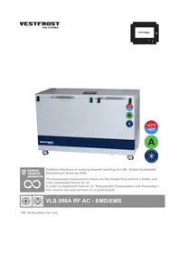


| Product Type | Refrigerator-freezer |
| Model | VLS 086A RF AC |
| Brand | Vestfrost |
| Height (cm) | 178 |
| Width (cm) | 54 |
| Depth (cm) | 58 |
| Weight (kg) | 55 |
| Net Capacity (L) | 200 |
| Refrigerator Capacity (L) | 150 |
| Freezer Capacity (L) | 50 |
| Power Supply | 220-240 V, 50 Hz |
| Energy Class | A |
| Refrigerant | R600a |
| Climate Class | N-ST |
| Adjustable Thermostat | Yes |
| Interior Lighting | LED |
| Reversible Door | Yes |
| Defrost Method | Automatic (fridge), manual (freezer) |
| Number of Shelves | 4 |
| Number of Freezer Drawers | 3 |
| Noise Level (dB) | 42 |
| Cleaning Recommendations | Use mild detergent with a soft cloth |
| Safety Certification | CE |
| Spare Parts Availability | Available from authorized service centers |
| Warranty | 2 years |
Frequently Asked Questions - VLS 086A RF AC VESTFROST
User questions about VLS 086A RF AC VESTFROST
0 question about this device. Answer the ones you know or ask your own.
Ask a new question about this device
Download the instructions for your Refrigerator in PDF format for free! Find your manual VLS 086A RF AC - VESTFROST and take your electronic device back in hand. On this page are published all the documents necessary for the use of your device. VLS 086A RF AC by VESTFROST.
USER MANUAL VLS 086A RF AC VESTFROST

12
RESPONSIBLE CONSUMPTION AND PRODUCTION

Vestfrost Solutions is working towards reaching the UN - Global Sustainable Development Goals by 2030.
The Sustainable Development Goals are the blueprint to achieve a better and more sustainable future for all.
In order to implement Goal no 12 "Responsible Consumption and Production", this manual has been printed on recycled paper.


VLS 086A RF AC - EMD/EMS
GB Instructions for use
WARNING
WARNING:
Keep ventilation openings in the appliance's cabinet or in the built-in structure clear of obstruction.
WARNING:
Do not use mechanical devices or other means to accelerate the defrosting process, other than those recommended by the manufacturer.
WARNING:
Do not damage the refrigerant circuit.
WARNING:
Do not use electrical appliances inside the storage compartment, unless they are of a type recommended by the manufacturer.

WARNING:
Danger: Risk of fire or explosion. Flammable refrigerant is used. To be repaired only by trained personnel.
WARNING:
When positioning the appliance, ensure the power cable is not trapped or damaged.
WARNING:
Do not locate multiple portable socket-outlets or portable power supplies at the rear of the appliance.
- Always keep the keys in a separate place and out of reach of children.
- Children should be supervised to ensure that they do not play with the appliance.
- This appliance is not intended for use by persons (including children) with reduced physical, sensory or mental capabilities, or lack of experience and knowledge, unless they have been given supervision or instruction concerning use of the appliance by a person responsible for their safety.
- Before servicing or cleaning the appliance, unplug the appliance from the mains or disconnect the electrical power supply.
- If the supply cord is damaged, it must be replaced by the manufacturer, its service agent, or similarly qualified persons in order to avoid a hazard.
- Frost formation on the interior evaporator wall and upper parts is a natural phenomenon. Therefore, the appliance should be defrosted during normal cleaning or maintenance.
- Please note that changes to the appliance construction will cancel all warranty and product liability.
- This appliance is intended to be used in household and similar applications.
- Do not store explosives, such as aerosol cans with flammable propellants in the unit.
Perform the following steps to prevent ESD damage:
- Use a wired ESD wrist strap that is properly grounded. Touching the chassis before handling parts does not ensure adequate ESD protection on parts sensitive to ESD damage.
- Handle all static-sensitive components in a static-safe area. If possible, use anti-static floor pads and workbench pads.
- When unpacking a static-sensitive component from its shipping carton, do not remove the component from the anti-static packing material until you are ready to install the component. Before unwrapping the anti-static packaging, ensure that you discharge static electricity from your body.
- Before transporting a static-sensitive component, place it in an anti-static container or packaging.

Contents
WARNING 2
Get to know your VLS 086A RF AC......6
Electrical connection for 115 volt....7
Electrical connection for 230 volt....7
Voltage stabilizers....8
HIGHLY IMPORTANT!......9
If FT2 are used 10
Placing, unpacking and general information....11
Operation and start up....13
Loading the appliance 15
How to connect the M2M captive barrel power cable from an ILR/SDD ....16
How to connect the USB-C interface to exchange data with an external EMD....17
Front panel commands Level 1 display ....18
Battery change 22
Maintenance of M2M 23
Condensation water drainage Vaccine compartment....24
Defrosting of Freezer compartment .....25
Auto drainage 26
Maintenance and cleaning......27
Trouble shooting....28
Warranty, spare parts and service ......29
Disposal....30
3-Year Warranty Statement ....31
Health and safety guidance – Warning!
Before any repair job be aware of following!
WARNING:
Before servicing or cleaning the appliance, disconnect it from power source.

WARNING:
Danger risk of fire or explosion. Flammable refrigerant used. To be repaired only by trained personnel.

| PQS Code | Model PQS Performance | specificationsSpecification reference: | PQS Independent type-testing protocolProduct verification protocol: |
| E003/ | VLS 086A RF AC | E003/RF03.7 E003/RF 03 | -VP5 |
Get to know your VLS 086A RF AC

fig. 1
Electrical connection for 115 volt
Wiring and connections in power supply systems must be all applicable to (local and national) electrical codes. Consult these code lengths and sizes prior to cabinet installation.
This device complies with relevant EU directives including Low Voltage Directive 2014/35/EU and Electromagnetic Compatibility Directive 2014/30/EU
The socket should be freely accessible.
Connect the appliance only to 115V 60Hz alternating current via a correctly installed earthed socket.
The socket must be fused with a 10-13 A fuse.
If the appliance is to be operated in a non-European country, check on the rating plate whether the indicated voltage and current correspond to the values of your mains supply.
Information regarding voltage, current or power are given on the rating plate
Check that the plug fits your type of socket. If it does not fit, have a qualified electrician to fit the plug. This appliance must be earthed.
Do not plug several appliances and the refrigerator into the same multiple power strip. The appliances should always be plugged into its own individual electrical outlet which has a voltage rating that matches the voltage listed on the appliances's rating plate. Ensure that the plug and socket matches and that the appliance is earthed.
Electrical connection for 230 volt
Wiring and connections in power supply systems must be all applicable to (local and national) electrical codes. Consult these code lengths and sizes prior to cabinet installation.
This device complies with relevant EU directives including Low Voltage Directive 2014/35/EU and Electromagnetic Compatibility Directive 2014/30/EU
The socket should be freely accessible.
Connect the appliance only to 220-240V 50/60Hz mains supply via a correctly installed earthed socket.
The socket must be fused with a 10-13 A fuse.
If the appliance is to be operated in a non-European country, check on the rating plate whether the indicated voltage and current correspond to the values of your mains supply.
Information regarding voltage, current or power are given on the rating plate
Check that the plug fits your type of socket. If it does not fit, procure an appliance cord with the correct plug or have a qualified electrician to fit the plug according to country standards. This appliance must be earthed.
Do not plug several appliances and the refrigerator into the same multiple power strip. The refrigerator should always be plugged into its own individual electrical outlet which has a voltage rating that matches the voltage listed on the refrigerator's rating plate. Ensure that the plug and socket matches and that the appliance is earthed.
Voltage stabilizers
In order to protect the electrical components, the appliance is equipped with an internal voltage stabilizer for extended input range, that will safeguard the equipment against high/low mains voltage, high/low spikes and surges protection in line with WHO/PQS E007/VS01-VP.6
The internal extended stabilizer monitors the mains voltage continuously. If the voltage rises or drops, the stabilizer will stabilize the output to ensure the voltage reaching the appliance remains constant at 230V(+/-2%) or 115V (+/-2%) within the operating range of the unit.
The appliance is able to operate within the limits of 110V to 285V for 230V rated appliance and within the limits of 82V go 159V for 115V rated appliances.
If the input voltage get outside the limits, the stabilizer will disconnect the output, thereby protecting the load.
Once the mains voltage returns within acceptable limits, the stabilizer will reconnect the output following a startup delay.
Delay in restoring supply:
When under or over-voltage cut-out has occurred and the input voltage has returned to the operating range, the output is automatically restored after the factory set delay time delay (3-3:30 minutes random) when the mains voltage again is within the recommended range and stable.
Standard operation instructions how to connect your appliance:
-
Connect the appliance cable to the junction box
-
Ensure that the switch on the appliance is turned OFF
-
Plug the appliance plug into the wall mains socket
-
Turn the power ON at the wall main socket
-
Turn the switch on the appliance ON
-
The internal stabilizer has a built-in AVS (Automatic Voltage Switcher). This will ensure that the load is not connected immediately. The delay will ensure that the mains is good before connecting the load and protects the equipment from rapid switching on and off.
-
Once the waiting period (3-4 min.) has passed, the stabilizer will release power to the appliance, and the cooling system will turn on


fig. 2
WARNING!
HIGHLY IMPORTANT!
- Make sure NEVER to place any commodities direct up against the refrigerator sensor cover.
Eg. Water-pack

fig. 3

- Bottom grid MUST be used, the baskets are optional as the unit is Grade A
If FT2 are used
The activated Fridge-tag must be placed immediately in its predetermined location. It is recommended and important to place the device in the centre of the refrigerator for an optimal temperature observation.
External sensor
Two hours before activating the device the external sensor must be placed in its predetermined location. It is recommended and important to place the external sensor in the centre of the refrigerator for an optimal temperature observation and to avoid any incorrect measurements when starting the device

fig. 5
Fridge-tag
Support

Placing, unpacking and general information
Unpacking
- Unpack the appliance and check that it has not been damaged. If you observe any damage, inform your supervisor.
- Check the rating for correct voltage and frequency.
- Open and remove all internal packing material.
Placing
Install the appliance in a dry and well ventilated place. Avoid installation near heat sources or in direct sunlight.
Place the appliance on the floor and make sure that it is level.
Adjustable castors
Once the appliances is positioned in the exact spot of operation the anti-vibration foot is lowered, and the caster wheel is lifted off the ground, making the equipment completely stationary
When your equipment needs to be moved out of the way, just raise the anti-vibration foot, and push it easily to a new location.

fig. 6
eam Lifting Procedure (When Casters Cannot Be Used)
- Minimum of four people required; more may be needed depending on the installation environment.
-
Bend at the knees, not the waist. Keep your back straight.
-
Grip the appliance securely, with the lifting straps positioned on each caster
- Lift from solid structural areas—never lift from doors, panels, or adjustable components.
- Lift together on the count of three, keeping the appliance close to your body.
- Move slowly and communicate continually with the lifting team.
- When lowering the appliance into place, set it down gently, keeping fingers and hands clear of pinch points.
CAUTION
Lift with four people

Using Casters (Flat Surfaces Only)
- Ensure all casters are unlocked before moving.
- Push, do not pull, using both hands on sturdy surfaces of the appliance.
- Move at a controlled walking speed.
- Once positioned, lock all casters to prevent unintended movement.
Important Safety Notice
Failure to follow these instructions may result in personal injury, appliance damage, or installation hazards. Always follow local workplace safety regulations and use proper lifting equipment when necessary.
Ventilation
It is important that the appliance is placed-well ventilated, so that air can circulate unhindered above, below, and around the appliance. fig.7 illustrates how the necessary air circulation can be ensured. There must be at least 30 mm clearance between the base of the appliance and the floor.
Ventilation openings in the appliance or in built-in structures must be kept clear.
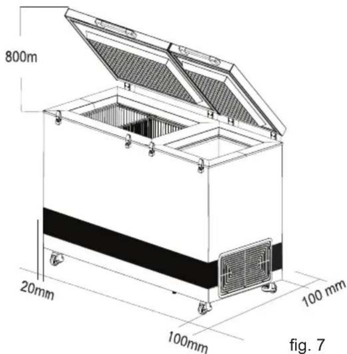
NOTE: There must be free access to the ventilation grille. (On the lower right side of the device)
Important:
Do not use open fire or cigarettes in the proximity of the appliance.
Room temperature
The appliance is designed and adjusted to produce an optimum temperature level in the vaccine compartment at a minimum/maximum ambient temperature of +5°C to +43°C.
NOTE: The appliance must not be placed in ambient temperatures below +5°C.
NOTE: Updated WHO PQS specifications: The temperature specifications of the vaccine storage refrigerator allow brief deviations from the general target of +2°C to +8°C.
Important to know
Vestfrost VLS Line is constructed with external and internal condensers.
The internal, also known as skin condensers, work by transferring the heat from the refrigeration system to the outer cabinet of the appliance and are not visible as they are located on the inside of the outer cabinet.
Especially, when the appliance is powered up the first time and must freeze the ice-lining until stabilization, (2-7 days) the outer cabinet will be heated up quite significantly, which should be expected, and it is completely OK.
Actually, a fine indication that the cooling system is working properly.

Operation and start up
Starting procedure
The appliance is designed to be always on, but can be switched off if necessary.
Connect the mains lead to the power supply.
Switch on the MCB on the back.
Through the cover to the compressor a red LED on the voltage stabilizer will be flashing for 5 minutes then turn blue if the supplied power is within range. The voltage stabilizer will turn on the output, activating the thermostat and the cooling system.
The Blue LED in the appliance lid will light blue whenever the supplied voltage is in range and the voltage stabilizer is active.
The green LED in the appliance's lid is to alert users that the cooling system is actively operating.
If the green LED light is on, it indicates that the compressor and cooling system are active, and when the light is off, the compressor and cooling system are off.
Turning the appliance off
If the appliance needs to be turned off, it is important to switch off the datalogger.
Level 1 display:
Long pressing the confirmation press

nd a short
It is important to switch off the MCB and disconnect the appliance when it is switched off. When power is reapplied, the thermostat will automatically restart the appliance.
Temperature control
It is recommended to check the inside temperature with an accurate thermometer twice a day. The inside temperature must be checked regularly according to WHO's standards and specifications.
Cool down of the appliance
Before the appliance is loaded with vaccines it is highly IMPORTANT to ensure it has fully stabilized the temperatures. It may take two to seven days to stabilize the temperature in a newly installed or repaired refrigerator and two to three days for a freezer. To ensure that the icelining is frozen and the appliance has stabilized do the following:
- Let the refrigerator run for at least 48
- Monitor the vaccine compartment temperatures from the EMS display.
- Check and record the minimum and maximum temperatures in the vaccine compartment each working day for two to seven days (must be between +2°C and +8°C).
If temperatures cannot be recorded digitally, check and record temperatures a minimum of two times each workday.
- Once you have two consecutive days of temperatures recorded within the recommended range, your unit is stable and ready for use.
The temperature in the vaccine compartment must always be monitored on the thermometer and be within the range +2° to +8°C.
Controller
The appliance is equipped with a thermostat that controls the temperature in the vaccine compartment. The thermostat is factory adjusted to a default setpoint, what in most ambient environments will keep the vaccine compartment within desired thresholds of 2°-8°C . If the refrigerator is not used for a longer period of time, it is recommended to use
ON/OFF switch 5 to turn the refrigerator OFF.
This disconnects the power from mains.

fig. 9
In case cooler is turned OFF, make sure the vaccine compartment is cleaned and dried thoroughly afterword's, this to prevent problems with odors or mold. To prevent odors taking hold it is highly recommended to keep the lid slightly open.
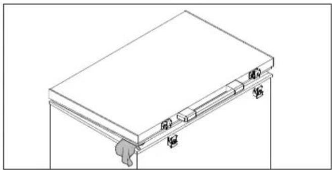
fig. 10
Charger
The appliance is equippe with a USB charger with USB type-A/C socket
The USB charger is only for charging remote temperature monitoring devices
USB output is on when there is sufficient solar radiation on the PV panels
The USB charger can supply up to 12V/35W.
The USB charger can deliver 100Wh/day on average depending on operating conditions.

fig. 11
Loading the appliance
Loading vaccines
When the temperature in the vaccine compartment has stabilized, i.e. and the temperature is between +2° and +8°C and the compressor stops and starts, vaccines can be loaded. The vaccines should be placed and arranged in the basket.
Vaccine storage
Below points are recommended vaccine storage advice outlined by Unicef
- Keep the vaccine boxes containing the vaccines in neat rows.
- Different vaccines should be kept separately to facilitate easy identification.
- Keep about, 2 cm. space between boxes of vaccines for circulation of air.
- Store Freeze sensitive vaccines (DPT, TT, IPV, Penta and Hep. B) away from the bottom of the ILR to avoid freezing. Always keep the vaccines in the basket provided in the ILR. OPV, RVV BCG, JE and Measles vaccine to be stored at bottom of basket of the ILR.
● Vaccine should be stored as per their heat and cold sensitivity.

Do not load the vaccine above top of the basket

fig. 13
Freezing waterpack:
Place waterpacks in the slots – after 24h the packs are frozen
Frozen waterpacks can be stored in the middle of the freezer

How to connect the M2M captive barrel power cable from an ILR/SDD

The barrel power cable is placed at the rear of the appliance, in the junction-box.

Example/Dummy of an External EMD, for instruction purposes only

- Cut the cable tie

- Prepare the cable make sure the barrel cable is ready for connection.

- Connect the barrel plug to EMD

How to connect the USB-C interface to exchange data with an external EMD

The USB-C socket is placed at the rear of the appliance, in the junction-box.
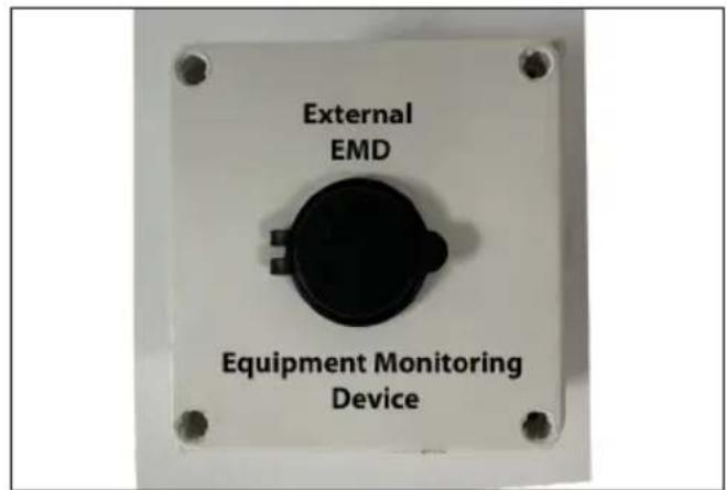


- Plug the USB-C male connector into theUSB-C socket located in the junction box's left side.


- Plug the USB-C male connector into the USB-C socket in the External EMD
Front panel commands Level 1 display

fig. 15
- Stand by/wake display. Long press plus confirmation press will put the device on standby/wake the device.
- (UP): To see the max. stored temperature; in programming mode it browses the parameter codes or increases the displayed value.
- (DOWN) To see the min stored temperature; in programming mode it browses the parameter codes or decreases the displayed value.
- Confirm. First press changes the temperature display to ice bank and lights up the ice cube symbol. Second press switches to hold over time and lights up the clock symbol. Returns automatically after 5 seconds.
- Cancel.

Refrigerator temperature.
- Freezer temperature. Is off if freezer is deselected
- Gr LED. Indicated if refrigerator compressor is running.
- Blue LED. Indicates that energy harvest is active. - Yellow LED. Indicates that either refrigerator or freezer lid is open.
- Blue LED, Indicates when there is data transfer on the USB port.
- BluOLED, Indicates that the ice bank temperature is shown in the display.
- Green LED, indicates that the remaining hold over time is shown in the display.
Alarms
In case of an alarm, the display will display the alarm code and the buzzer will sound an alarm.
An alarm can be muted by pressing any button. The display shall still display the alarm code.
During alarm, the display will alternate between the alarm code and the temperature.
Pressing the button after muting, will reset the alarm.
During battery operation, only high and low surface temperature sensor alarms will be set. (if the temperature is high, there is no longer a charged ice bank and the remaining battery capacity can be used to send alarms)
The device is equipped with an integrated datalogger in accordance with PQS DL01. The datalogger records the vaccine temperature and relevant additional measurements. Please see annex XX1 for full list
The data can be accessed through the USB C port on the back of the refrigerator. The port is marked with "logger data access, USB type C" symbol. By connected a suitable device (Windows pc, smartphone, EMD level2/3) the data can be accessed. The datalogger will present itself as a USB storage device. The data is stored in a 60-day PDF report and json files per PQS.
How to access data:
Connect a suitable device. The port presents itself as an USB mass storage device, please ensure that your device can handle this protocol.
Transfer the files from the USB storage to your device. The device is read only, so it is not possible to save data to it.
N.B. The device will automatically disconnect after 4 minutes. After additional 6 minutes, the device will be available again. This is to enable the datalogger to update the recorded data.
Powering your EMD level 2/3:
The refrigerator is equipped with the 5V power supply for powering EMD level 2/3. The power supply can deliver 1A. The power is available through a barrel plug on the back of the refrigerator. The plug is labelled "5V Monitoring Power"
Energy Harvest:
The refrigerator is equipped with an energy harvest device to deliver excess power when not needed by the refrigerator. The energy is available through an USB charge port on the back of the refrigerator. USB A and USB C porta are available. UP to 35W can be delivered through the USB port.
The port is inactive when the refrigerator is requiring power.
The port is marked "EHC"
Annex xx1
- RELT;Relative Time;Required
• RTCW;RTC Wakeup;Required
• TVC; Vaccine Compartment Temperature; Required - TFRZ;Freezer Compartment Temperature Required, if applicable
• TICE; Ice bank temperature; Manufacturer
• TSUR;Surface temperature;Manufacturer
• TAMB; Ambient temperature; Required - HAMB;Ambient relative humidity;Optional
• DORV;Door/lid opening (vaccine compartment);Required
• DRCV;Number of door/lid openings (vaccine compartment);Optional - DORF;Door/lid opening (freezer/other compartment);Required, if applicable
- DRCF;Number of door/lid openings (freezer/other compartment);Optional
- CMPR; Compressor runtime; Required, if applicable
- CMPR2;Secondary Compressor runtime;Required, if applicable
• FANS;Fan speed;Optional -
DCSV;DC supply voltage to the appliance;Required, for solar
-
DCCD;DC current drawn by the appliance;Required, for solar
• SVD;DC Supply voltage availability;Manufacturer - ACSV;AC supply voltage to the appliance;Optional
- ACCD;AC current drawn by the appliance;Optional
• SVA;AC supply voltage availability;Required, for mains
• BLOG;Logger battery remaining;Required - HOLD;Holdover, autonomy, or independence time;Optional
- TLO_ALARM; total time in seconds below low temp alarm limit; Manufacturer
- THI_ALARM;total time in seconds above high temp alarm limit ;Manufacturer
• ALRM;Alarm condition;Optional - LERR;Logger Error codes;Required
• AMOD;Appliance model;Required
• AMFR;Appliance manufacturer;Required
• ASER;Appliance manufacturer serial number;Required - ADOP;Appliance date of production;Required
• APQS;Appliance PQS code;Required - ACAT;Appliance PQS device type;Required
• CNAM; Compressor Electronic Unit Manufacturer; Required, if applicable - CSER; Compressor Electronic Unit Product Code; Required, if applicable
- CSOF; Compressor Electronic Unit Software version; Required, if applicable
-
CNAM2;Secondary Compressor Electronic Unit Manufacturer;Required, if applicable
-
CSER2;Secondary Compressor Electronic Unit Product Code;Required, if applicable
• CSOF2;Secondary Compressor Electronic Unit Software version;Required, if applicable - LDOP;Logger date of production;Required
• LMFR;Logger manufacturer;Required - LMOD;Logger model;Required
• LPQS;Logger PQS code;Required - LSER;Logger serial number;Required
- LSV;Logger software version;Required
- TVC; Vaccine Compartment Temperature; Required
- TFRZ;Freezer Compartment Temperature ;Required, if applicable
- IDRV; Instantaneous door/lid opening (vaccine compartment); Required in sync file
- IDRF; Instantaneous door/lid opening (freezer compartment); Required in sync file
List of alarms and error codes
The following alarms are monitored and logged:
| Alarm type Thres- | hold | Dura-tion | Blanking period | List of Error Codes |
| LoA (low temperature) AL1 | Ad1 Ab1 A | - Vaccine temp. | sensor error | |
| HiA (high temperature) AH1 | Ad2 Ab2 B | - Ambient temp. | sensor error | |
| Lid 1 open L1T L1A C - Ice | bank temp. | sensor error | ||
| Lid 2 open L2A D - Surface | temp. | sensor error | ||
| Low battery datalogger Lbd | E - Freezer temp. | sensor error | ||
| Low battery EMS Lbe F - Vaccine comp. | door malfunction | |||
| Real time clock battery low | G - Freezer comp. | door malfunction | ||
| High temperature freezer | H - Power measure-ment error | |||
| DC barrel plug fault | I - Compressor 1 malfunction | |||
| Heating cable short circuit | J - Compressor 2 malfunction | |||
| Heating cable open circuit | K - Fan malfunction | |||
| Fan blocked | Z - Missing/incomplete data records |
Blanking period is the time from the unit is turned on until the alarm is activated, giving the refrigerator time to cool down. This is done to avoid false alarms.
Battery change

WARNING:
Before changes or cleaning the appliance, disconnect it from power source.

- To unmount the display unfasten the 4 Torx 20 screws

- Power wire connection to electronic control unit

- Gently place a small screwdriver, under the top part of the display cover and twist the screwdriver to unlock the 3 fixing points

- Battery position
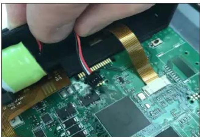
- By hand gently press the lock function on both sides of the power wire plug and slide backwards. The power wire is loose
Maintenance of M2M
1. Keep It Clean
- Use compressed air or a soft brush to remove dust/debris from the plug and port.
- For sticky dirt, gently wipe the metal connector with isopropyl alcohol and a lint-free cloth.
2. Avoid Excessive Force
- Plug and unplug gently—USB-C is reversible, but forcing it can bend internal pins.
- Never yank it out by the cable; grip the connector instead.
3. Protect from Moisture
- Avoid using USB-C devices in wet or humid environments.
- If the plug gets wet, dry it thoroughly before use.
4. Use Quality Cables
- Low-quality or damaged cables can damage your device. Stick to certified brands.
- Inspect regularly for fraying, loose connectors, or overheating.
5. Store Properly
- Don't tightly bend or wrap the cable around plugs.
- Use a case or cable organizer to keep it safe when not in use
Condensation water drainage Vaccine compartment
Due to humidity in the air combined with cold surfaces inside the vaccine compartment, it should be expected that condensation will form on the sides of the inner lining. The condensation will be collected at the bottom, from where it regularly needs to be drained. If the bottom of the vaccine compartment is covered with condensation water, drainage/drying should be initiated.
Condensation increases if:
• Equipment is opened too frequently.
- Lid not closing properly.
- Lid gasket is defective.
• High level of humidity.
Drainage of condensation water is recommended to performed in the morning between 7am to 9am when the ambient temperatures are expected to be lowest.
Proceed as follows:
IMPORTANT!
Before condensation drainage vaccines must be moved to another working ILR, SDD or cold box with conditioned icepacks.
- Disconnect the power supply by switching off the ON/OFF power button or disconnect plug from power socket.
- Open the drainage plug, placed inside the vaccine compartment. If the appliance has an auto-drainage system, there is no plug to open. Instead, ensure that the drainage filter is cleaned. See fig. 20
-
Place a tray under the condensation water drain. If the appliance has an auto-drainage system, no need for tray. See fig. 17
-
When all the condensation and water droplets on the lining has been removed carefully, clean the inside cabinet, as well as lid, lid gasket, and outside of the cabinet, using water with a mild, perfume-free detergent. Dry the vaccine compartment with a soft cloth, and make sure, no moisture is remaining after cleaning.
-
Reinsert the internal drainage plug, and check lid gasket is not faulty.
-
Reconnect the power supply by the ON/OFF power button and/or reconnect power plug.
-
When appliance has regained required safe temperatures for storing vaccines 2°-8°C , place the vaccines in neat rows with space.

fig. 16
Defrosting of Freezer compartment
The water-packs stored and the humidity of the air gradually causes frost and ice to form in the freezer compartment. A thin layer of frost or ice does not affect freezer performance, but a thick layer could cause the freezer not to cool water-packs satisfactory. Small amounts of loose frost can be removed using a plastic scraper.
Never use electrical apparatus or sharp implements as these may damage the inside of the appliance.
When the layer of frost and ice exceeds 4-5 mm the freezer should be completely defrosted.
Defrosting should be performed in the morning between 7am to 9am, just before the solar radiation again is powerful enough to start compressor and run refrigeration system. For ILR's no specific time of defrosting is recommended
Proceed as follows:
- Disconnect the power supply by switching off the ON/OFF button. Important! ONLY switch off the power supply of the freezer compartment.
- Remove all water-packs from freezer compartment. Place them in an empty coldbox or wrap them up to keep them as cold as possible.
- Keep the freezer lid open.
- Unscrew the drain plug placed front right-hand side underneath the appliance.
- Place a tray under the defrost water drain.
-
Place a bowl of hot (but not boiling) water in the freezer, close the lid and wait approx. 30 minutes before removing loose frost with the plastic scraper.
-
To prevent water from damaging the floor during defrosting, it is advisable to check the defrost water tray from time to time and to cover the floor around the defrost water drain to protect against ice and splashes. When all the frost and ice have melted, clean the inside cabinet, as well lid, lid gasket, and outside of the cabinet using water with a mild, perfume-free detergent. Dry the freezer with a soft cloth, and make sure no moisture is remaining after cleaning.
- Reinsert the internal and external drainage plugs, and check lid gasket is not faulty.
- Important! Screw back in position the drain plug, and turn on again the power supply with the ON/OFF button.
- Check waterpacks are not leaking before returning them to the freezer compartment. Place waterpacks according instructions, approx. 5 minutes after having switched it on. Close the lid.

fig. 17
Auto drainage
The appliance is equipped with an auto-drainage function, with a drain hole at the bottom of the vaccine compartment.
The drain is collecting the water droplets generated by the unavoidable condensation that at some point will be created on the inner linings of the vaccine compartment, due to the fact of warm air hitting the cold surface of the wall.
This condensation eventually will run down the sides to the bottom, and water then flows down the drain tube into a drip tray located on top of the compressor which evaporates the liquid as it warms.
If the appliance drain becomes blocked by any objects, the water can't drain away as it should from the vacciencompartment, which will result in water accumulating, which further could result in creating issues with the stored vaccine vials, stickers, cardboard boxes, etc.
This is why it is an important SOP procedure, to regularly ensure that the drain filter is clean and free from dirt and waste.
To do the cleaning, use lukewarm water with a mild cleaning agent on a soft cloth, and wipe off the filter along with the surrounding bottom.
Finish off with a dry dishtowel or similar, to ensure all objects are removed and the bottom is dry.
This is why it is an important SOP procedure, to regularly ensure that the drain filter fig.20 is clean and free from dirt and waste.

fig.18

fig.19
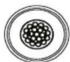
fig.20
Maintenance and cleaning
Maintenance of the appliance
Daily maintenance:
The temperature in the vaccine compartment must always be monitored on the thermometer every morning and evening. Please note that the vaccine in the appliance may not freeze. The temperature is factory set, and should not be adjusted by unauthorized personnel. Check lid is properly closed and fits tightly to the cabinet of the appliance.
Weekly maintenance:
During normal use, water can accumulate at the bottom of the appliance; remove with a cloth or through the drainage hole. Wipe off water droplets on the inside wall at the same time.
Check if lid gasket is sealing tight to the top frame when the lid is closed. A tight sealing lid reduces accumulation of water and formation of rime significantly.
Monthly maintenance:
Clean the grille on the right side of the refrigerator once each month. Clean vaccine compartment with lukewarm water and mild detergent Clean outside of refrigerator with lukewarm water and mild detergent
Yearly maintenance:
Electric connections and components are to be checked and cleaned once a year or more if necessary.
Cleaning
Disconnect the power supply before cleaning by using the on/off switch placed at the junction box at the rear of the appliance. The best way to clean the appliance is by using luke warm water with a small amount of unscented detergent. Never use cleaning agents that scour. Use a soft cloth. Rinse with clean water and dry thoroughly. It is important to prevent water from running into the control panel.
The gasket around the lid must be cleaned regularly to prevent discolouration and prolong service life. Use clean water. After cleaning the gasket, check that it continues to provide a tight seal.
If the appliance is not being used for any period of time, switch the appliance off, disconnect the power supply, empty the appliance, clean the inside, and leave the lid open to allow air circulation and prevent smells.
Trouble shooting
| Fault Possible cause Remedy | ||
| Compressor is not running | Be patient, it is most likely that the compressor will start within a few minutes. | If this is not the case, check the following:- Check that power is connected- Check the fuse and replace it if necessary.- If the above is OK, call technical supervisor. |
| Compressor is running, and the temperature is too high | The ventilation grille is blocked.The lid is not closed properly.The temperature in the room in which the appliance is installed is too high. | Ensure unhindered air circulation.Ensure that the lid is closed properly.Shield the appliance against direct sun light and ensure more ventilation to the room. |
| No temperature is displayed | The micro processor control unit is brokenPower not connected | Change the micro processor control unit.Check power outlet - Check power plug is connected. |
Warranty, spare parts and service
Warranty disclaimer
Faults and damage caused directly or indirectly by incorrect operation, misuse, insufficient maintenance, incorrect building, installation or mains connections. Fire, accident, lightning, voltage variation or other electrical interference, including defective fuses or faults in mains installations are not covered by the warranty.
Repairs performed by others than approved service centres and any other faults and damage that the manufacturer can substantiate are caused by reasons other than manufacturing or material faults are not covered by the warranty.
Please note that changes to the construction of the appliance or changes to the component equipment of the appliance will invalidate warranty and product liability, and the appliance cannot be used lawfully. The approval stated on rating plate will also be invalidated.
Before calling for technical assistance, please check whether you are able to rectify the fault yourself. If your request for assistance is unwarranted, e.g. if the appliance has failed as a result of a blown fuse or incorrect operation, you will be charged the costs incurred by your call for technical assistance.
Spare parts
When ordering spare parts, please state the type, serial and product numbers of your appliance. This information is given on the rating plate (fig.17). The rating plate contains various technical information, including type and serial numbers.

fig. 21
Disposal
Information for Users on Collection and Disposal of Old Equipment and used Batteries

These symbols on the products, packaging, and/or accompanying documents mean that used electrical and electronic products and batteries should not be mixed with general household waste. For proper treatment, recovery and recycling of old products and used batteries, please take them to applicable collection points, in accordance with your national legislation and the Directives 2012/19/EU and 2006/66/EC.
By disposing of these products and batteries correctly, you will help to save valuable resources and prevent any potential negative effects on human health and the environment which could otherwise arise from inappropriate waste handling.
For more information about collection and recycling of old products and batteries, please contact your local municipality, your waste disposal service or the point of sale where you purchased the items.
Penalties may be applicable for incorrect disposal of this waste, in accordance with national legislation.

For business users in the European Union.
If you wish to discard electrical and electronic equipment, please contact your dealer or supplier for further information.
Information on Disposal in other Countries outside the European Union
These symbols are only valid in the European Union. If you wish to discard this product, please contact your local authorities or dealer and ask for the correct method of disposal.
Note for the battery symbol:

This symbol might be used in combination with a chemical symbol. In this case it complies with the requirement set by the Directive for the chemical involved.
This product contains flammable refrigerant and lithium battery. Avoid damage of the refrigerating circuit when disposed and send to applicable collection point.
3-Year Warranty Statement
Vestfrost offers a 36-month warranty from the date of shipment for all cold chain equipment.
The warranty covers any component failure arising from:
• Manufacturer-related issues
- Production errors
- Defective design
• Defective materials
• Defective workmanship
The warranty does not cover:
• Equipment failure due to abuse, misuse, or use for purposes other than intended
- Incorrect installation
- Lack of preventive maintenance
• Normal wear and tear from regular use
- Any event not caused by production or hardware errors
- Loss of contents stored in the appliance
Claim Procedures in Case of Equipment Failure or Underperformance
- Remote Service: If end users can solve the problem via phone, the local service partner or Vestfrost Technical department will assist with troubleshooting according to the Vest-frost recommendations and training.
- On-site Service: A local service partner or Vestfrost will visit the site with properly trained technical personnel equipped with tools, service manuals, spare parts, etc., to perform maintenance/service on-site.
- Off-site Service: If the issue cannot be resolved through the above two options, the Vest-frost Local Service Partner (LSP) will transport the unit to their authorized workshop for repair.
- Swop Service: If the issue cannot be resolved by the three options, Vestfrost will deliver a new unit to the country's central MoH warehouse as o replacement the faulty unit. To ensure the best service, it is important to log and register faulty equipment using the Vestfrost Claim Report, including the following information:
To ensure the best service, it is important to log and register faulty equipment with the following information:
- Serial number (very important)
- Model
- Problem description and pictures (troubleshooting)
- Contact information, phone number, and email of the person reporting the issue
Contact Vestfrost Solutions or an authorized sales and service partner for assistance.
This warranty shall be governed by the laws of your country.
Contact information of Vestfrost Technical support department:
Phone: +45 75 74 22 50
Email: technicalsupport@vestfrostsolutions.com
Adress: Falkevej 12, Esbjerg, Denmark


12
RESPONSIBLE CONSUMPTION AND PRODUCTION

Vestfrost Solutions is working towards reaching the UN - Global Sustainable Development Goals by 2030.
The Sustainable Development Goals are the blueprint to achieve a better and more sustainable future for all.
In order to implement Goal no 12 "Responsible Consumption and Production", this manual has been printed on recycled paper.


VLS 086A RF AC - EMD/EMS
- WARNING
- PERFORM THE FOLLOWING STEPS TO PREVENT ESD DAMAGE
- CONTENTS
- HEALTH AND SAFETY GUIDANCE – WARNING
- GET TO KNOW YOUR VLS 086A RF AC
- ELECTRICAL CONNECTION FOR 115 VOLT
- INFORMATION REGARDING VOLTAGE, CURRENT OR POWER ARE GIVEN ON THE RATING PLATE
- ELECTRICAL CONNECTION FOR 230 VOLT
- VOLTAGE STABILIZERS
- HIGHLY IMPORTANT
- IF FT2 ARE USED
- EXTERNAL SENSOR
- PLACING, UNPACKING AND GENERAL INFORMATION
- UNPACKING
- PLACING
- ADJUSTABLE CASTORS
- EAM LIFTING PROCEDURE (WHEN CASTERS CANNOT BE USED)
- USING CASTERS (FLAT SURFACES ONLY)
- IMPORTANT SAFETY NOTICE
- VENTILATION
- IMPORTANT
- ROOM TEMPERATURE
- IMPORTANT TO KNOW
- OPERATION AND START UP
- STARTING PROCEDURE
- TURNING THE APPLIANCE OFF
- LEVEL 1 DISPLAY
- TEMPERATURE CONTROL
- COOL DOWN OF THE APPLIANCE
- CONTROLLER
- CHARGER
- LOADING THE APPLIANCE
- LOADING VACCINES
- VACCINE STORAGE
- FREEZING WATERPACK
- HOW TO CONNECT THE M2M CAPTIVE BARREL POWER CABLE FROM AN ILR/SDD
- HOW TO CONNECT THE USB-C INTERFACE TO EXCHANGE DATA WITH AN EXTERNAL EMD
- FRONT PANEL COMMANDS LEVEL 1 DISPLAY
- ALARMS
- HOW TO ACCESS DATA
- POWERING YOUR EMD LEVEL
- ENERGY HARVEST
- ANNEX XX
- LIST OF ALARMS AND ERROR CODES
- BATTERY CHANGE
- MAINTENANCE OF M2M
- KEEP IT CLEAN
- AVOID EXCESSIVE FORCE
- PROTECT FROM MOISTURE
- USE QUALITY CABLES
- STORE PROPERLY
- CONDENSATION WATER DRAINAGE VACCINE COMPARTMENT
- DEFROSTING OF FREEZER COMPARTMENT
- PROCEED AS FOLLOWS
- AUTO DRAINAGE
- MAINTENANCE AND CLEANING
- MAINTENANCE OF THE APPLIANCE
- DAILY MAINTENANCE
- WEEKLY MAINTENANCE
- MONTHLY MAINTENANCE
- YEARLY MAINTENANCE
- CLEANING
- TROUBLE SHOOTING
- WARRANTY, SPARE PARTS AND SERVICE
- WARRANTY DISCLAIMER
- SPARE PARTS
- DISPOSAL
- YEAR WARRANTY STATEMENT
- CLAIM PROCEDURES IN CASE OF EQUIPMENT FAILURE OR UNDERPERFORMANCE
Brand : VESTFROST
Model : VLS 086A RF AC
Category : Refrigerator