MHO900 - Uncategorized Rigol - Free user manual and instructions
Find the device manual for free MHO900 Rigol in PDF.


| Type of product | Digital Storage Oscilloscope |
| Brand | Rigol |
| Model | MHO900 |
| Bandwidth | 100 MHz |
| Number of channels | 2 |
| Maximum sample rate | 1 GSa/s |
| Record length | 12 Mpts |
| Display | 7-inch color TFT LCD |
| Power supply | 100-240 VAC, 50/60 Hz |
| Dimensions (W x H x D) | 313 x 176 x 90 mm |
| Weight | 2.4 kg |
| Main functions | Waveform acquisition, FFT analysis, automatic measurements, multiple trigger modes |
| Interfaces | USB host/device, LAN, VGA |
| Maintenance | Clean the exterior with a soft dry cloth; avoid liquid cleaners |
| Safety notes | CAT II overvoltage protection; grounding required |
| Spare parts and repairability | Replacement probes and power cords available; service by qualified personnel |
| General information | Suitable for education, field service and bench testing |
Frequently Asked Questions - MHO900 Rigol
User questions about MHO900 Rigol
0 question about this device. Answer the ones you know or ask your own.
Ask a new question about this device
Download the instructions for your Uncategorized in PDF format for free! Find your manual MHO900 - Rigol and take your electronic device back in hand. On this page are published all the documents necessary for the use of your device. MHO900 by Rigol.
USER MANUAL MHO900 Rigol
Guaranty and Declaration
Copyright
© 2025 RIGOL TECHNOLOGIES CO., LTD. All Rights Reserved.
Trademark Information
RIGOL® is the trademark of RIGOL TECHNOLOGIES CO., LTD.
Software Version
Software upgrade might change or add product features. Please acquire the latest software version from RIGOL website or contact RIGOL to upgrade the software.
Notices
- RIGOL products are covered by P.R.C. and foreign patents, issued and pending.
- RIGOL reserves the right to modify or change parts of or all the specifications and pricing policies at the company's sole decision.
• Information in this publication replaces all previously released materials.
• Information in this publication is subject to change without notice.
- RIGOL shall not be liable for either incidental or consequential losses in connection with the furnishing, use, or performance of this manual, as well as any information contained.
- Any part of this document is forbidden to be copied, photocopied, or rearranged without prior written approval of RIGOL.
Product Certification
RIGOL guarantees that this product conforms to the national and industrial standards in China as well as the ISO9001:2015 standard and the ISO14001:2015 standard. Other international standard conformance certifications are in progress.
Contact Us
If you have any problem or requirement when using our products or this manual, please contact RIGOL.
E-mail: service@rigol.com
Website: http://www.rigol.com
1 Safety Requirement
1.1 General Safety Summary
Please review the following safety precautions carefully before putting the instrument into operation so as to avoid any personal injury or damage to the instrument and any product connected to it. To prevent potential hazards, please follow the instructions specified in this manual to use the instrument properly.
1 Only the exclusive power cord designed for the instrument and authorized for use within the destination country could be used.
8 Do not operate the instrument with suspected failures.
2 Ensure that the instrument is safely grounded.
9 Provide adequate ventilation.
3 Observe all terminal ratings. 10 Do not operate in wet conditions.
4 Use proper overvoltage protection.
11 Do not operate in an explosive atmosphere.
5 Do not operate without covers. 12 Keep instrument surfaces clean and dry.
6 Do not insert objects into the air outlet.
13 Prevent electrostatic impact.
7 Avoid circuit or wire exposure. 14 Handle with caution.

WARNING
Equipment meeting Class A requirements may not offer adequate protection to broadcast services within residential environment.

WARNING
This product is a non-isolated oscilloscope. The ground (GND) for each input and output interface is not isolated from the metal chassis or the digital interface grounds (such as USB and HDMI). Do not perform floating measurements without using isolated probes, nor connect any port's GND to a port with a voltage difference relative to earth ground. Otherwise, it may cause damage to this product or other devices (such as the DUT or a computer display) connected to the product and can even cause serious personal injury.
1.2 Safety Notices and Symbols
Safety Notices in this Manual:

WARNING
Indicates a potentially hazardous situation or practice which, if not avoided, will result in serious injury or death.

CAUTION
Indicates a potentially hazardous situation or practice which, if not avoided, could result in damage to the product or loss of important data.
Safety Notices on the Product:
• DANGER
It calls attention to an operation, if not correctly performed, could result in injury or hazard immediately.
- WARNING
It calls attention to an operation, if not correctly performed, could result in potential injury or hazard.
- CAUTION
It calls attention to an operation, if not correctly performed, could result in damage to the product or other devices connected to the product.
Safety Symbols on the Product:

Hazardous Voltage

Safety Warning Protective Earth
Terminal


Chassis Ground Test Ground
1.3 Measurement Category
Measurement Category
This instrument can make measurements in Measurement Category I.

WARNING
This instrument can only be used for measurements within its specified measurement categories.
Measurement Category Definitions
- Measurement category I is for measurements performed on circuits not directly connected to MAINS. Examples are measurements on circuits not derived from MAINS, and specially protected (internal) MAINS derived circuits. In the latter case, transient stresses are variable. Thus, you must know the transient withstand capability of the equipment.
- Measurement category II is for measurements performed on circuits directly connected to low voltage installation. Examples are measurements on household appliances, portable tools and similar equipment.
- Measurement category III is for measurements performed in the building installation. Examples are measurements on distribution boards, circuit-breakers, wiring (including cables, bus-bars, junction boxes, switches and socket-outlets) in the fixed installation, and equipment for industrial use and some other equipment. For example, stationary motors with permanent connection to a fixed installation.
- Measurement category IV is for measurements performed at the source of a low-voltage installation. Examples are electricity meters and measurements on primary overcurrent protection devices and ripple control units.
1.4 Ventilation Requirement
This instrument uses a fan to force cooling. Please make sure that the air inlet and outlet areas are free from obstructions and have free air. When using the instrument in a bench-top or rack setting, provide at least 10 cm clearance beside, above and behind the instrument for adequate ventilation.

CAUTION
Inadequate ventilation may cause an increase of temperature in the instrument, which would cause damage to the instrument. So please keep the instrument well ventilated and inspect the air outlet and the fan regularly.
1.5 Working Environment
Temperature
Operating: 0°C to +50°C
Non-operating: -30°C to +60°C
Humidity
- Operating:
Below +30°C: ≤90%RH (without condensation)
+30°C to +40°C: ≤75% RH (without condensation)
+40°C to +50°C: ≤45%RH (without condensation)
- Non-operating:
Below +60°C: ≤90%RH (without condensation)

WARNING
To avoid short circuit inside the instrument or electric shock, never operate the instrument in a humid environment.
Altitude
- Operating: below 3 km
• Non-operating: below 15 km
Protection Level Against Electric Shock
ESD ±8kV
Installation (Overvoltage) Category
This product is powered by mains conforming to installation (overvoltage) category II.

WARNING
Ensure that no overvoltage (such as that caused by a bolt of lightning) can reach the product. Otherwise, the operator might be exposed to the danger of an electric shock.
Installation (Overvoltage) Category Definitions
Installation (overvoltage) category I refers to signal level which is applicable to equipment measurement terminals connected to the source circuit. Among these terminals, precautions are done to limit the transient voltage to a low level.
Installation (overvoltage) category II refers to the local power distribution level which is applicable to equipment connected to the AC line (AC power).
Pollution Degree
Pollution Degree 2
Pollution Degree Definition
- Pollution Degree 1: No pollution or only dry, nonconductive pollution occurs. The pollution has no effect. For example, a clean room or air-conditioned office environment.
- Pollution Degree 2: Normally only nonconductive pollution occurs. Temporary conductivity caused by condensation is to be expected. For example, indoor environment.
- Pollution Degree 3: Conductive pollution or dry nonconductive pollution that becomes conductive due to condensation occurs. To be found in industrial
environment or construction sites (harsh environments). For example, sheltered outdoor environment.
- Pollution Degree 4: The pollution generates persistent conductivity caused by conductive dust, rain, or snow. For example, outdoor areas.
Safety Class
Class 2
1.6 Care and Cleaning
Care
Do not store or leave the instrument where it may be exposed to direct sunlight for long periods of time.
Cleaning
Clean the instrument regularly according to its operating conditions.
- Disconnect the instrument from all power sources.
- Clean the external surfaces of the instrument with a soft cloth dampened with mild detergent or water. Avoid having any water or other objects into the chassis via the heat dissipation hole. When cleaning the LCD, take care to avoid scarifying it.

CAUTION
To avoid damage to the instrument, do not expose it to caustic liquids.

WARNING
To avoid short-circuit resulting from moisture or personal injuries, ensure that the instrument is completely dry before connecting it to the power supply.
1.7 Environmental Considerations
The following symbol indicates that this product complies with the WEEE Directive 2012/19/EU.

The equipment may contain substances that could be harmful to the environment or human health. To avoid the release of such substances into the environment and avoid harm to human health, we recommend you to recycle this product appropriately to ensure that most materials are reused or recycled properly. Please contact your local authorities for disposal or recycling information.
You can click on the following link https://int.rigol.com/services/services/declaration to download the latest version of the RoHS&WEEE certification file.
2 Document Overview
This manual gives you a quick review about the front and rear panel of MHO900 series digital oscilloscope, its user interface, and the basic operation method.

TIP
For the latest version of this manual, download it from the official website of RIGOL (http://www.rigol.com).
Publication Number
QGA46101-1110
Software Version
Software upgrade might change or add product features. Please acquire the latest version of the manual from RIGOL website or contact RIGOL to upgrade the software.
Format Conventions in this Manual
1. Key
The front panel key is denoted by the menu key icon. For example, indicates the "DEFAULT" key.

2. Menu
The menu item is denoted by the format of "Menu Name (Bold) + Character Shading" in the manual. For example, Setup indicates clicking or tapping the Setup sub-menu under the "Utility" function menu to view the basic setting configuration items.
3. Operation Procedures
The next step of the operation is denoted by ">" in the manual. For example,

Storage indicates that first clicking or tapping the icon 📋, then clicking or tapping Storage.
4. Connector
The connectors on the front or rear panel are denoted by the format of "Connector Name (Bold) + Square Brackets (Bold)". For example, [AUX OUT].
Content Conventions in this Manual
MHO900 series digital oscilloscope includes the following models. Unless otherwise specified, this manual takes MHO984 as an example to illustrate the functions and operation methods of MHO900 series oscilloscope.
| Model Max. Analog Bandwidth No. of Analog Channels | ||
| MHO984 | 800 MHz (single-channel[1]& half-channel[2])400 MHz (all-channel[3]) | 4 |
| MHO954 | 500 MHz (single-channel[1]& half-channel[2])400 MHz (all-channel[3]) | 4 |
| MHO934 350 MHz (for any number of channels) 4 | ||

NOTE
[1]: Single-channel mode: If any one of the channels is enabled, it is called single-channel mode.
[2]: Half-channel mode: If two of the channels are enabled, it is called half-channel.
[3]: All-channel mode: If all of the channels are enabled or any three of the channels are enabled, it is called all-channel mode.
3 General Inspection
1. Inspect the packaging
If the packaging has been damaged, do not dispose the damaged packaging or cushioning materials until the shipment has been checked for completeness and has passed both electrical and mechanical tests.
The consigner or carrier shall be liable for the damage to the instrument resulting from shipment. RIGOL would not be responsible for free maintenance/rework or replacement of the instrument.
2. Inspect the instrument
In case of any mechanical damage, missing parts, or failure in passing the electrical and mechanical tests, contact your RIGOL sales representative.
3. Check the accessories
Please check the accessories according to the packing lists. If the accessories are damaged or incomplete, please contact your RIGOL sales representative.
Recommended Calibration Interval
RIGOL suggests that the instrument should be calibrated every 18 months.
4 Product Overview
MHO900 series is RIGOL's new launched economical oscilloscope. Compact in size, it features 1,000,000 wfms/s [1] capture rate (in fast recording mode), up to 500 Mpts memory depth (option), 12-bit high resolution and low noise.

NOTE
[1]: Single-channel mode, recording mode, 20 ns/div, 1 kpts memory depth (or Auto memory depth).
4.1 Appearance and Dimensions

Figure 4.1 Front View

Figure 4.2 Side View
4.2 Front Panel
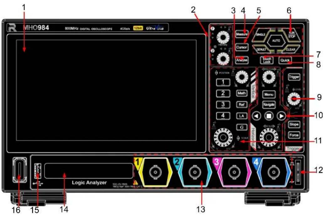
Figure 4.3 Front Panel
1 7" Capacitive Multi-touch Screen 9 Trigger Control Area
2 Multifunction Knob 10 Horizontal Control Area
3 Analyse Key 11
Vertical Control Area [1]
4 Measure Key 12 Probe Compensation Signal
Output Terminal/Ground Terminal
5 Cursor Key 13 Analog Channel Input Terminals
6 Common Operation Key 14 Digital Channel Input Terminal
7 Touch Screen Lock Key 15 USB HOST Interface
8 Quick Operation Key (Related to quick operation setting) 16 Power Key

NOTE
[1]: In the vertical control area, indicates the Function/Arbitrary Waveform Generator (AFG) key. GI and GII connectors are standard hardware configuration. To use the Function/Arbitrary Waveform Generator (Bode plot function supported) function, you need to install the AFG50 or AFG100 option according to your need.
4.3 Rear Panel

Figure 4.4 Rear Panel
1 Function/Arbitrary Waveform Generator Output Interface GI/GII [1]
2 AUX OUT Output Interface
3 LAN Interface
4 USB DEVICE Interface
5 HDMI Video Output Interface
6 USB Type-C Power Interface
7 Security Lock Hole
8 Ground Terminal
9 Bracket Mounting Hole (VESA 100x100)

NOTE
[1]: Available to use when the AFG option has been installed.
4.4 User Interface

Figure 4.5 User Interface
1 Waveform View 8 Multi-pane Windowing Display Area
2 Operating Status 9 Notification Area
3 Horizontal Timebase and Horizontal Position Label
4 Sample Rate & Memory Depth Label
5 Trigger Information Label 12 Digital Channel Label
6 Quick Operation Toolbar 13 Channel Status Label
7 Result List 14 Function Navigation Icon
5 To Prepare for Use
5.1 To Adjust the Supporting Legs
Adjust the supporting legs properly to use them as stands to tilt the oscilloscope upwards for stable placement of the oscilloscope, making it easy to operate and better to observe waveforms. You can also fold the supporting legs when the instrument is not in use for easier storage or shipment, as shown in the following figure.

(a) Unfold the supporting legs

(b) Fold the supporting legs
Figure 5.1 To Adjust the Supporting Legs
5.2 To Connect to AC Power
The power requirements of the oscilloscope are DC, 20 V, 5 A. Please use the power adapter provided in the accessories to connect the oscilloscope to the AC power source (100 V to 240 V, 50 Hz to 60 Hz), as shown in the following figure.

Figure 5.2 Connect to AC Power
Table 5.1 Power Adapter Specification
| Parameter Remarks | |
| Input 100 V to 2 | 40 V, 50 Hz to 60 Hz, 1.6 A Max |
| Output DC, 20 V, 5 A, 100 W | |

CAUTION
The power adapter provided in the accessories can only be used for RIGOL specified products. Do not use it to charge the mobile phone or other devices.

WARNING
To avoid electric shock, use the ground cable provided in the accessories to connect the instrument to the ground properly.
5.3 Turn-on Checkout
After the instrument is connected to the power source, press the power key at the lower-left corner of the front panel to power on the instrument. During the start-up process, the instrument performs a series of self-tests. After the self-test, the splash screen is displayed.
- Restart: Click or tap the function navigation icon at the lower-left corner of the screen to enter the function navigation. Click or tap Power > Restart to restart the instrument.
- Shutdown:
- Click or tap the function navigation icon at the lower-left corner of the screen to enter the function navigation. Click or tap Power > Shutdown to shut down the instrument.
- Press down the power key 0, then the power state switching window is displayed. Click or tap Shutdown to shut down the instrument.
- Press the power key 0 continuously for two times to turn off the instrument.
- Long press the power key for three seconds to turn off the instrument.
• Low Power Mode:
Click or tap the function navigation icon at the lower-left corner of the screen to enter the function navigation. Click or tap Power > Low Power Mode to enter the low power mode.
In the low power mode, the instrument has the following characteristics.
- It can start quickly with low power consumption. The instrument can be waken up in just a few seconds. Then it automatically recovers all of its configurations prior to the low power mode.
- Low power consumption: In this mode, the screen is off. Most of the measurement hardware (e.g. ADC, front-end amplifier) will be disconnected or enter the low power consumption mode. At this time, the power consumption of the instrument is far less than that in its normal operating state.
- Many ways to wake up the instrument: To wake up the instrument, press any key on the front panel or rotate the knob. You can also send the SCPI command :SYSTem:LOWPower 0 via the communication interface to wake up the instrument.

NOTE
Note that once it enters the low power mode, the last captured waveform data will not be saved when you wake it up from the low mode mode. If necessary, please remember to save the data manually before it enters the low power mode.

TIP
You can also click or tap > Utility > Setup. Then select "Switch On" for the "Power status" menu. After the instrument is connected to power source, it will start directly.
5.4 To Set the System Language
This oscilloscope supports multiple languages. You can click or tap > Utility > Setup > Language to select the system language.
5.5 To Connect the Probe
RIGOL's MHO900 series oscilloscope provides the passive probe and the logic analyzer probe (option). For specific probe models, please refer to MHO900 DataSheet. For detailed technical information of the probes, please refer to the corresponding Probe User Guide.
Connect the Passive Probe
-
Connect the BNC terminal of the probe to the front-panel analog channel input terminal of the oscilloscope, as shown in the figure below.
-
Connect the ground alligator clip or spring of the probe to the circuit ground terminal, and then connect the probe tip to the circuit point to be tested.

Figure 5.3 Connect the Passive Probe
After you connect the passive probe, check the probe function and probe compensation adjustment before making measurements. For detailed procedures, refer to Function Inspection and Probe Compensation.
Connect the Logic Probe
- Connect the output terminal of the logic probe to the front-panel digital channel input terminal of the oscilloscope in the correct direction, as shown in the figure below.
- Connect the input terminal of the logic probe to the signal terminal under test. MHO900 series has an optional configuration of PLA2216 active logic analyzer probe. To apply to different application scenarios, PLA2216 provides two connection methods to connect the signal under test. For details, refer to PLA2216 Active Logic Probe User Guide.

Figure 5.4 Connect the Logic Probe

CAUTION
The digital channel input terminal does not support hot plugging. Please do not insert or pull out the logic probe when the instrument is in power-on state.
TIP
- For ground connection of high-speed signals, the ground lead shall be connected to the ground test point near the measured signal, and the ground lead shall be kept as short as possible.
- If there are a large number of input signal channels, please connect each signal to a ground signal as far as possible. If there is only one ground test point, connect all ground leads on the probe to the ground test point.
- Set a proper threshold value for the logic probe according to the actual level range of the signal under test. Set the threshold value to the middle of the level range.
5.6 Function Inspection
-
Press ON the front panel, then a prompt message displaying "Restore default settings?" appears on the screen. Click OK to restore the instrument to its factory default settings.
-
Connect the ground alligator clip of the probe to the "Ground Terminal" as shown in Figure 5.5 below.
-
Use the probe to connect the input terminal of CH1 of the oscilloscope and "Compensation Signal Output Terminal" shown in Figure 5.5.

Figure 5.5 Use the Compensation Signal
-
Set the probe ratio based on the attenuation of the probe, and then click > Auto.
-
Observe the waveform on the display. In normal condition, the square waveform as shown in the figure below should be displayed.

Figure 5.6 Square Waveform Signal
- Use the same method to test the other channels. If the signal appears but not properly displayed or deformed, please perform the instructions specified in Probe Compensation. If no signal appears, please perform the above steps again.

WARNING
To avoid electric shock when using the probe, please make sure that the insulated wire of the probe is in good condition. Do not touch the metallic part of the probe when the probe is connected to high voltage source.
5.7 Probe Compensation
When used for the first time, the oscilloscope probe must be compensated to match the input characteristics of the oscilloscope channel to which it is connected. The non-compensated or poorly compensated probe may cause measurement errors. The compensation procedure is as follows:
- Perform Step 1, 2, 3 and 4 in Function Inspection.
- Check the displayed waveforms and compare them with the waveforms shown in
Figure 5.7.

Over compensated Under compensatedPerfectly compensated
Figure 5.7 Probe Compensation
- Use the probe compensation adjustment tool provided in the accessories to adjust the low-frequency compensation adjustment hole on the probe until the displayed
waveform is consistent with the "Perfectly compensated" waveform shown in the above figure.
6 Touch Screen Gestures
The instrument provides a super large capacitive touch screen, which is convenient for users to operate and make configurations. It has strong waveform display capacity and excellent user experience. It features great convenience, high flexibility, and great sensitivity. The actions supported by the touch screen controls include tapping, pinching&stretching, and dragging.
6.1 Tap
Use one finger to tap the symbol or characters on the screen slightly, as shown in Figure 6.1. With the Tap gesture, you can perform the following operations:
- Tap the menu displayed on the screen to operate on the menu.
- Tap the function navigation icon at the lower-left corner of the touch screen to enable the function navigation.
- Tap the displayed numeric keypad to set the parameters.
- Tap the virtual keypad to set the label name and the filename.
- Tap the close button at the upper-right corner of the message box to close the prompt window.
- Tap other windows on the touch screen and operate on the windows.

Figure 6.1 Tap Gesture
6.2 Drag
Use one finger to select the object, and then drag the object to a destination place, as shown in the figure below. With the drag gesture, you can perform the following operation:
- Drag the waveform to change its position or scale.
- Drag the window controls to change the position of the window (e.g. numeric keypad).
- Drag the cursor to move the cursor.
- Drag the trigger cursor to change the trigger level.
- In multi-window display, drag one of the displayed windows to change its position on the display.

Figure 6.2 Drag Gesture
6.3 Pinch&Stretch
Pinch or stretch two points on the screen with two fingers to zoom in or out the waveform. To zoom in the waveform, first pinch the two fingers and then stretch the fingers; to zoom out the waveform, first stretch the two fingers, and then pinch the fingers together, as shown in the figure below. With the pinch&stretch gesture, you can perform the following operation:
- Pinching&stretching in the horizontal direction can adjust the horizontal time base of the waveform.
- Pinching&stretching in the vertical direction can adjust the vertical scale of the waveform.

Figure 6.3 Pinch&Stretch Gesture
7 To Use the Built-in Help System
The built-in help file provides information about the functions and menu
introductions of the instrument. Click or tap > Help to enter the help system.
In the help system, you can get its help information by clicking on or tapping the link for the specified chapter.
8 Parameter Setting Method
For this instrument, you can use the knob and touch screen to set parameters. The common parameter setting methods are as follows:
- Method 1: Some parameters can be adjusted by rotating the knob on the front panel.
- Method 2: Click or tap the input field of a specified parameter, then a virtual keypad is displayed. Complete the parameter setting with the keypad.
Input a Value
When setting or modifying a parameter, input an appropriate value with the numeric keypad.
- Click or tap the value or unit in the numeric keypad to complete the input.
- Rotate the multipurpose knob (1/2) to move the cursor to select the desired value and unit. Press the knob to confirm the input.

Figure 8.1 Numeric Keypad
After you input all the values and select the desired units, the numeric keypad is turned off automatically. This indicates that you have completed parameter setting. Besides, after you have input the values, you can also click or tap "OK" directly to close the numeric keypad. At this time, the unit of the parameter is the default unit. In the numeric keypad, you can perform the following operations:
- Modify the parameter value that has been input;
- Set the parameter value to a maximum or minimum value;
- Set the parameter to a default value;
- Clear the parameter input field.
9 Bluetooth Setting
In the Utility menu, click or tap Bluetooth to enter the Bluetooth setting menu. You can connect the oscilloscope to the mouse and keyboard via bluetooth, enabling the mouse control or keyboard input for the oscilloscope.
Click or tap the Bluetooth switch to select ON to enbale the bluetooth function. Click or tap the Search button and the search device menu will pop up. In the pop-up search device menu, the oscilloscope will scan for available Bluetooth devices within range. The paired devices are displayed at the top of the search device menu.
After pairing successfully, devices are saved in the "Paired Device" list. In the Paired Device menu, click or tap Unpair to unpair the Bluetooth connection of the device from the oscilloscope.

NOTE
Connect the WIFI& Bluetooth adapter to the USB port on the front panel of the oscilloscope first. WLAN and Bluetooth function are only available when the WIFI& Bluetooth adapter is recognized by the oscilloscope.
10 WLAN Setting
In the Utility menu, click or tap WLAN to enter the WLAN setting menu. You can connect the oscilloscope to a wireless network.
Click or tap the WLAN switch to select ON to enable the WLAN function. Click or tap Search and the WIFI list menu is displayed. Available WLANs are displayed in the list, and you can select a desired network for connection. When a secured wireless network is selected, a password input field is displayed. Enter the password and click or tap the Connect button, then the oscilloscope connects to this wireless network.
Click or tap the Saved button and the saved menu is displayed. In this menu, you can view previously connected wireless networks. Click or tap the Remove button of the specified network to remove the previously connected wireless network.

NOTE
- Connect the WIFI& Bluetooth adapter to the USB port on the front panel of the oscilloscope first. WLAN and Bluetooth function are only available when the WIFI& Bluetooth adapter is recognized by the oscilloscope.
- The WLAN of the oscilloscope does not support connecting to SSIDs that require network authentication.
11 Remote Control
The following ways of remote control are supported:
- User-defined Programming
Users can program and control the instrument by using the SCPI (Standard Commands for Programmable Instruments) commands. For details about the SCPI commands and programming, refer to Programming Guide of this product series.
- Web Control
The instrument supports the Web Control function. Web Control is a browser-based remote control technology that allows the user to remotely access and control the instrument over the network without additional software installation. By using the web browser to remotely access the networked instrument, the control terminals (e.g. PC, Mobile, iPad, and other smart terminals) display the instrument interface in real time. Users can view device information, adjust the oscilloscope's timebase and vertical sensitivity, configure trigger conditions, and more. Operation Procedures are as follows:
1. Connect the instrument to the network
First ensure that the rear-panel LAN interface is connected to the network. Note that the instrument must be connected to and accessed through the network that located in the same network domain as the control terminal.
2. Obtain the instrument IP address
Click or tap the function navigation icon 📄 at the lower-left of the screen. Click or tap Utility, and view the instrument IP address under the IO menu.
- Type the instrument IP address into the browser address bar and press Enter, and the following interface will be displayed.

- Click Web Control on the left side of the screen to enter the instrument remote control interface. You can use the mouse to remotely control the instrument in real time, with the same effect as operating the instrument directly.
- Click Print Screen, and you can select "Take Screenshot" or "Record Screen" to capture the current display content.
- Click Network Settings to configure the network. Note that login is required when changing the network configuration. The default username and password for first-time Web Control login are "admin" and "rigol".
- The SCPI Panel Control function allows the user to send SCPI commands through the web interface for remote programming control of the instrument. Click SCPI Panel Control and enter the commands in the SCPI Command input field. After entering the commands, click the Send&Read button to control the instrument remotely. For details about the SCPI commands and programming, refer to Programming Guide of this product series.
- Close the browser to exit the instrument remote control interface.
The instrument IP address allows only one user to log in for remote login control. Concurrent logins are not allowed. If the connection is interrupted, you can refresh the browser to load the page.

CAUTION
Before connecting the communication cable, please turn off the instrument to avoid causing damage to the communication interfaces.
12 More Product Information
Click or tap 🖱️ > Utility > About to obtain the information of the instrument, such as the model, serial number, and hardware version number.
For more information about this instrument, refer to the relevant manuals by logging in to the official website of RIGOL (http://www.rigol.com) to download them.
- MHO900 User Guide introduces the functions of the instrument and the operation methods, remote control methods, possible failures and solutions in using the instrument, the technical specifications, and order information.
- MHO900 Programming Guide provides detailed descriptions of SCPI commands and programming examples of the instrument.
- MHO900 Data Sheet provides the main features and technical specifications of the instrument.
Boost Smart World and Technology Innovation
Industrial Intelligent Manufacturing


Semiconductors

Education& Research
![graph TD A["RIGOL"] --> B["5G"] A --> C["Wireless Devices"] A --> D["Smart Home Appliance"] B --> E["Robot"] C --> F["Lightbulb"] D --> G["Water Heater"] E --> H["Neural Network"] F --> I["Smart Home Device"] G --> J["Smart Home Appliance"] H --> K["Smart Home Appliance"] I --> L["Smart Home Applian…](/content/2026/08/1629639/images/17d35d10124df7aeee07b50d9674786678c9d3586f33364818c1867c51a26063.jpg)

Communication
System Integration


New Energy

Cellular-5G/WIFI

UWB/RFID/ZIGBEE

Digital Bus/Ethernet

Optical Communication

Digital/Analog/RF Chip

Memory and MCU Chip

Third-Generation Semiconductor

Solar Photovoltaic Cells

New Energy Automobile

PV/Inverter

Power Test

Automotive Electronics
Provide Testing and Measuring Products and Solutions for Industry Customers
HEADQUARTER
RIGOL TECHNOLOGIES CO., LTD.
No.8 Keling Road, New District,
Suzhou,JiangSu,P.R.China
Tel: +86-400620002
Email: info-cn@rigol.com
JAPAN
RIGOL JAPAN CO., LTD.
5F,3-45-6,Minamiotsuka,Toshima-Ku,
Tokyo,170-0005,Japan
Tel: +81-3-6262-8932
Fax: +81-3-6262-8933
Gangseo-gu, Seoul, Republic of Korea
Tel: +82-2-6953-4466
Fax: +82-2-6953-4422
Email: info.kr@rigol.com
NORTH AMERICA
RIGOL TECHNOLOGIES, USA INC.
10220 SW Nimbus Ave.
Suite K-7
Portland, OR 97223
Tel: +1-877-4-RIGOL-1
Email: sales@rigol.com
For Assistance in Other Countries
Email: info.int@rigol.com
- GUARANTY AND DECLARATION
- COPYRIGHT
- TRADEMARK INFORMATION
- SOFTWARE VERSION
- NOTICES
- PRODUCT CERTIFICATION
- CONTACT US
- SAFETY REQUIREMENT
- GENERAL SAFETY SUMMARY
- WARNING
- SAFETY NOTICES AND SYMBOLS
- CAUTION
- DANGER
- MEASUREMENT CATEGORY
- MEASUREMENT CATEGORY DEFINITIONS
- VENTILATION REQUIREMENT
- WORKING ENVIRONMENT
- TEMPERATURE
- HUMIDITY
- OPERATING
- ALTITUDE
- PROTECTION LEVEL AGAINST ELECTRIC SHOCK
- INSTALLATION (OVERVOLTAGE) CATEGORY
- INSTALLATION (OVERVOLTAGE) CATEGORY DEFINITIONS
- POLLUTION DEGREE
- POLLUTION DEGREE DEFINITION
- SAFETY CLASS
- CARE AND CLEANING
- CARE
- CLEANING
- ENVIRONMENTAL CONSIDERATIONS
- DOCUMENT OVERVIEW
- TIP
- PUBLICATION NUMBER
- FORMAT CONVENTIONS IN THIS MANUAL
- KEY
- MENU
- OPERATION PROCEDURES
- CONNECTOR
- CONTENT CONVENTIONS IN THIS MANUAL
- NOTE
- GENERAL INSPECTION
- INSPECT THE PACKAGING
- INSPECT THE INSTRUMENT
- CHECK THE ACCESSORIES
- RECOMMENDED CALIBRATION INTERVAL
- PRODUCT OVERVIEW
- APPEARANCE AND DIMENSIONS
- FRONT PANEL
- REAR PANEL
- USER INTERFACE
- TO PREPARE FOR USE
- TO ADJUST THE SUPPORTING LEGS
- TO CONNECT TO AC POWER
- TURN-ON CHECKOUT
- SHUTDOWN
- LOW POWER MODE
- TO SET THE SYSTEM LANGUAGE
- TO CONNECT THE PROBE
- CONNECT THE PASSIVE PROBE
- CONNECT THE LOGIC PROBE
- FUNCTION INSPECTION
- PROBE COMPENSATION
- TOUCH SCREEN GESTURES
- TAP
- DRAG
- PINCH&STRETCH
- TO USE THE BUILT-IN HELP SYSTEM
- PARAMETER SETTING METHOD
- INPUT A VALUE
- BLUETOOTH SETTING
- WLAN SETTING
- REMOTE CONTROL
- USER-DEFINED PROGRAMMING
- WEB CONTROL
- CONNECT THE INSTRUMENT TO THE NETWORK
- OBTAIN THE INSTRUMENT IP ADDRESS
- MORE PRODUCT INFORMATION
- BOOST SMART WORLD AND TECHNOLOGY INNOVATION
- PROVIDE TESTING AND MEASURING PRODUCTS AND SOLUTIONS FOR INDUSTRY CUSTOMERS
- HEADQUARTER
- JAPAN
- NORTH AMERICA
- FOR ASSISTANCE IN OTHER COUNTRIES
Brand : Rigol
Model : MHO900
Category : Uncategorized