
MAG B850 TOMAHAWK MAX WIFI II - Motherboard MSI - Free user manual and instructions
Find the device manual for free MAG B850 TOMAHAWK MAX WIFI II MSI in PDF.


| Product Type | Motherboard |
| Manufacturer | MSI |
| Model | MAG B850 TOMAHAWK MAX WIFI II |
| Form Factor | ATX |
| CPU Socket | AMD Socket AM5 |
| Chipset | AMD B850 |
| Memory Support | 4x DDR5 DIMM, up to 256GB |
| Memory Speed | Up to 6400+ MHz (OC) |
| PCIe Slots | 1x PCIe 5.0 x16, 1x PCIe 4.0 x16 |
| M.2 Slots | 4x M.2 (supports PCIe 5.0) |
| SATA Ports | 6x SATA 6Gbps |
| LAN | 2.5Gbps Ethernet |
| Wireless Connectivity | Wi-Fi 7, Bluetooth 5.4 |
| Audio | High Definition Audio codec (Realtek ALC4080) |
| USB Ports | USB 3.2 Gen2, USB4 support |
| Power Connectors | 24-pin ATX, 8+8-pin CPU |
| RGB Software | MSI Mystic Light |
| Debug Tools | EZ Debug LED, BIOS Flashback |
| Dimensions | 305mm x 244mm |
| Weight | 1.4kg |
| Accessories | SATA cables, Wi-Fi antenna, screws |
| Safety | Short-circuit protection, overcurrent protection |
Frequently Asked Questions - MAG B850 TOMAHAWK MAX WIFI II MSI
User questions about MAG B850 TOMAHAWK MAX WIFI II MSI
0 question about this device. Answer the ones you know or ask your own.
Ask a new question about this device
Download the instructions for your Motherboard in PDF format for free! Find your manual MAG B850 TOMAHAWK MAX WIFI II - MSI and take your electronic device back in hand. On this page are published all the documents necessary for the use of your device. MAG B850 TOMAHAWK MAX WIFI II by MSI.
USER MANUAL MAG B850 TOMAHAWK MAX WIFI II MSI
Specifications....17
Special Features....21
Package Contents 22
Back Panel Connectors ....23
LAN Port LED Status Table 24
Audio Jacks Connection.... 24
Installing Antenna.... 26
Overview of Components ....27
CPU Socket....28
DDR5 DIMM Slots.... 30
PCI_E1\~3: PCIe Expansion Slots 32
M2_1\~4: M.2 Slots (Key M) 35
SATA_A1\~A4: SATA 6Gb/s Connectors.... 41
JAUD1: Front Audio Connector 41
JFP1, JFP2: Front Panel Connectors 42
CPU_PWR1\~2, ATX_PWR1, PCIE_PWR1: Power Connectors 43
JCI1: Chassis Intrusion Connector 44
JUSBC1: USB 20Gbps Type-C Front Panel Connectors 44
JUSB2\~3: USB 5Gbps Connectors.... 45
JUSB4\~5: USB 2.0 Connectors 45
JTPM1: TPM Module Connector 46
JOC_FS1: Safe Boot Jumper 46
JBAT1: Clear CMOS (Reset BIOS) Jumper 47
JBCLK1\~2: BCLK Frequency Jumpers 47
CPU_FAN1, PUMP_SYS1, SYS_FAN1\~6: Fan Connectors 48
JRGB1: RGB LED connector 49
JARGB_V2_1\~3: A-RAINBOW V2 (ARGB Gen2) LED connectors 50
JAF_2: EZ Conn-Header V2....51
Onboard LEDs....53
EZ Debug LED....53
EZ Memory Detection LED 53
Installing OS, Drivers & MSI Center ....54
Installing Drivers with MSI Driver Utility Installer.... 55
UEFI BIOS....58
BIOS Setup 59
Entering BIOS Setup 60
Resetting BIOS 61
Updating BIOS 61
Block Diagram....63
Regulatory Notices......i
Quick Start
This Quick Start provides clear diagrams to help you install the motherboard. Video demonstrations are also available for some installations. Visit these videos by clicking the provided URL on your phone or tablet’s web browser. Alternatively, you can scan the QR code to access the video directly.
Preparing Tools and Components

A Package of Screws
Safety Information
- The components included in this package are prone to damage from electrostatic discharge (ESD). Please adhere to the following instructions to ensure successful computer assembly.
- Ensure that all components are securely connected. Loose connections may cause the computer to not recognize a component or fail to start.
- Hold the motherboard by the edges to avoid touching sensitive components.
- It is recommended to wear an electrostatic discharge (ESD) wrist strap when handling the motherboard to prevent electrostatic damage. If an ESD wrist strap is not available, discharge yourself of static electricity by touching another metal object before handling the motherboard.
- Store the motherboard in an electrostatic shielding container or on an anti-static pad whenever the motherboard is not installed.
- Before turning on the computer, ensure that there are no loose screws or metal components on the motherboard or anywhere within the computer case.
- Do not boot the computer before installation is completed. This could cause permanent damage to the components as well as injury to the user.
- If you need help during any installation step, please consult a certified computer technician.
- Always turn off the power supply and unplug the power cord from the power outlet before installing or removing any computer component.
- Keep this user guide for future reference.
- Keep this motherboard away from humidity.
- Make sure that your electrical outlet provides the same voltage as is indicated on the PSU, before connecting the PSU to the electrical outlet.
- Place the power cord such a way that people can not step on it. Do not place anything over the power cord.
- All cautions and warnings on the motherboard should be noted.
- If any of the following situations arises, get the motherboard checked by service personnel:
- Liquid has penetrated into the computer.
- The motherboard has been exposed to moisture.
- The motherboard does not work well or you can not get it work according to user guide.
- The motherboard has been dropped and damaged.
- The motherboard has obvious sign of breakage.
- Do not leave this motherboard in an environment above 60° C ( 140° F), it may damage the motherboard.
Case stand-off notification
To prevent damage to the motherboard, any unnecessary mounting stand-off between the motherboard circuits and the computer case is prohibited. The Case standoff keep out zone signs will be marked on the backside of motherboard (as shown below) to serve as a warning to user.
Avoid collision notification
Protective paint is printed around each screw hole to prevent parts from being scratched.
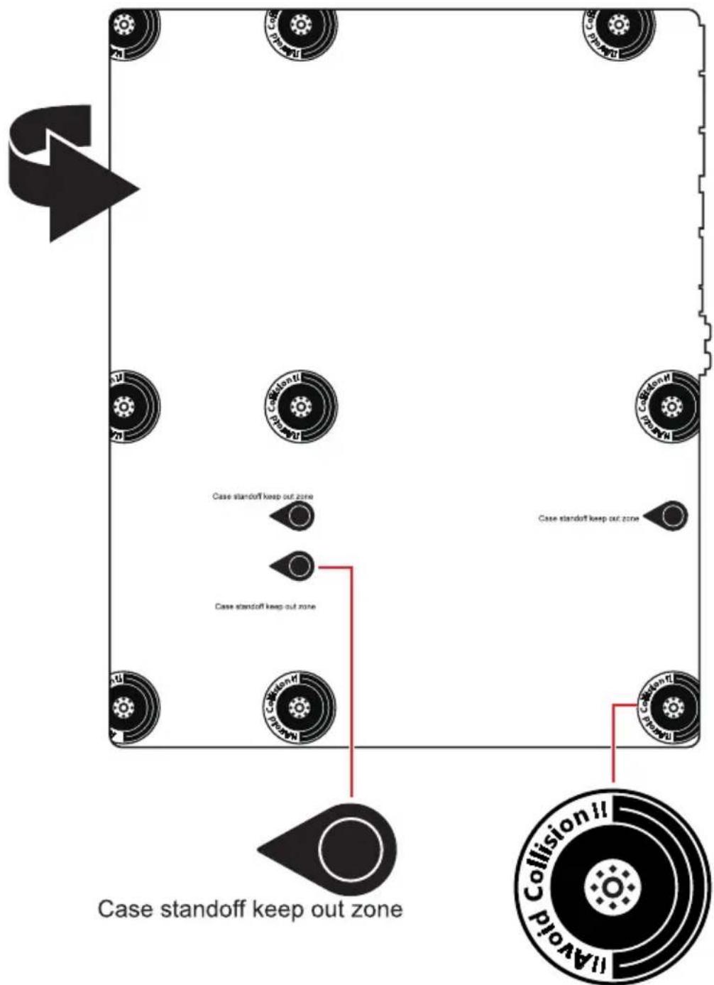
* The illustration above is for reference only and may vary from the motherboard you purchased.
Installing a Processor

- https://msi.gm/SDBE5855

If you are installing the screw-type CPU heatsink, please follow the figure below to remove the retention module first and then install the heatsink.

Installing DDR5 memory

- https://msi.gm/S647FF99


Connecting the Front Panel Header


- https://msi.gm/S8EF7577

Installing the Motherboard
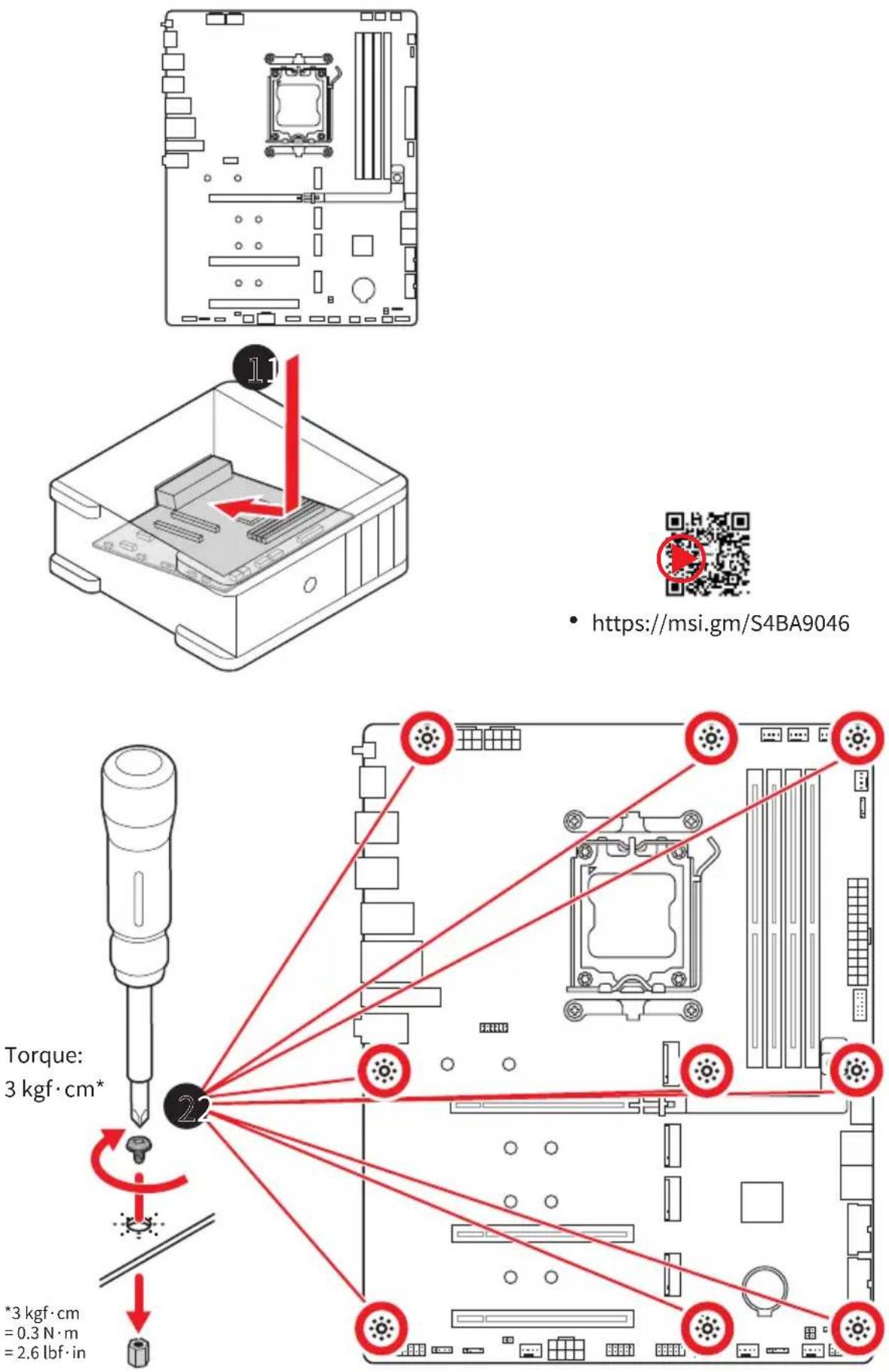
- https://msi.gm/S4BA9046
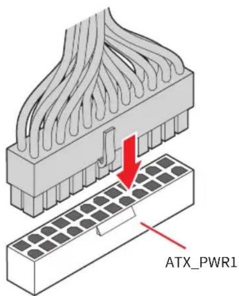
Connecting the Power Connectors

- https://msi.gm/SD937E2C


Installing SATA Drives

- https://msi.gm/S9369131

Installing a Graphics Card

- https://msi.gm/S6B36811

Connecting Peripheral Devices

Power On

Specifications
| CPU | Supports AMD RyzenTM 9000/ 8000/ 7000 Series Desktop Processors*Processor socket AM5* Please go to www.msi.com to get the newest support status as new processors are released. |
| Chipset | AMD B850 Chipset |
| Memory | 4x DDR5 memory slots*, supporting up to 256GB**Supports AMD POR Speed and JEDEC SpeedSupports Memory Overclocking and AMD EXPOTMSupports Dual-Channel modeSupports Non-ECC, Un-buffered memorySupports CUDIMM, Clock Driver bypass mode only***The DIMM slots on this motherboard only have single-sided latches.** Memory compatibility and supported speeds can vary depending on the CPU and memory configuration. For detailed information, please refer to the Memory Compatibility List available on the product's Support page or visit https://www.msi.com/support/.*** CUDIMM support and POR boot frequency may vary by CPU series, with manual overclocking available after boot. Certain CPUs may fail to boot, but future BIOS updates will improve compatibility. |
| Expansion Slots | 3x PCIe x16 slotsPCI_E1 slot (From CPU)Supports PCIe 5.0 x16 (For RyzenTM 9000/ 7000 Series processors)Supports PCIe 4.0 x8 (For RyzenTM 8700/ 8600/ 8400 Series processors) SupportSupports PCIe 4.0x4 (For RyzenTM 8500/ 8300 Series processors)PCI_E2 slot (From B850 chipset)Supports up to PCIe 3.0 x1PCI_E3* slot (From B850 chipset)Supports up to PCIe 4.0 x4* PCI_E3 slot will run at x2 speed when installing device in the M2_3 slot. |
| Onboard Graphics | 1x HDMITM 2.1 with FRL port, supporting a maximum resolution of 4K 120Hz or 8K 60Hz*/ *** Available only on processors featuring integrated graphics.** Graphics specifications may vary depending on the CPU installed. |
| SATA Ports | 4x SATA 6Gb/s ports (From ASM1064) |
Continued on next column
Continued from previous column
| M.2 SSD Slots | 4x M.2 slots (Key M)M2_1 slot (From CPU)Supports up to PCIe 5.0 x4 (For RyzenTM 9000/ 7000 Series processors)Supports up to PCIe 4.0 x4 (For RyzenTM 8000 Series processors)Supports 2280/ 22110 storage devicesM2_2 slot (From CPU)Supports up to PCIe 5.0 x4 (For RyzenTM 9000/ 7000 Series)Supports up to PCIe 4.0 x4 (For RyzenTM 8700/ 8600/ 8400 Series processors)Supports up to PCIe 4.0 x2 (For RyzenTM 8500/ 8300 Series processors)Supports 2260/ 2280 storage devicesM2_3* slot (From Chipset)Supports up to PCIe 4.0 x2Supports 2260/ 2280 storage devicesM2_4 slot (From Chipset)Supports up to PCIe 4.0 x4Supports 2260/ 2280 storage devices* PCI_E3 slot will run at x2 speed when installing device in the M2_3 slot. |
| RAID | Supports RAID 0, RAID 1, RAID 5 and RAID 10 for M.2 NVMe storage devicesRAID 5/ 10 configuration is only supported by RyzenTM 9000/ 7000 series processors. |
| Audio | Realtek® ALC4080 Codec7.1-Channel USB High Performance AudioSupports up to 32-Bit/384 kHz playback on front panelSupports S/PDIF output |
| LAN | 1x Realtek® 8126 5Gbps LAN controller |
Continued on next column
Continued from previous column
| Wi-Fi & Bluetooth® | Wi-Fi 7The Wireless module is pre-installed in the M.2 (Key-E)slotSupports MU-MIMO TX/RX, 2.4GHz/ 5GHz/ 6GHz* (320MHz) up to 5.8GbpsSupports 802.11 a/ b/ g/ n/ ac/ ax/ beSupports Bluetooth® 5.4**, MLO, 4KQAM* 6GHz band support may depend on every country's regulations and Wi-Fi 7 will be ready in Windows 11 version 24H2.** The Bluetooth version may be updated, please refer to the Wi-Fi chipset vendor's website for details. Bluetooth 5.4 will be ready in Windows 11 version 24H2. |
| Power Connectors | 1x 24-pin ATX main power connector2x 8-pin +12V power connectors1x 8-pin PCIe power connector |
| Internal USB Connectors | 1x USB 20Gbps Type-C front panel port (From B850 chipset)2x USB 5Gbps connectors (From Hub-GL3523)Supports additional 4 USB 5Gbps ports2x USB 2.0 connectors (From B850 chipset)Supports additional 4 USB 2.0 ports |
| Fan Connectors | 1x 4-pin CPU fan connector1x 4-pin water-pump/ system fan connector6x 4-pin system fan connectors |
| System Connectors | 1x Front panel audio connector2x System panel connectors1x Chassis Intrusion connector1x TPM module connector1x EZ Conn-Header V2 (JAF_2) |
| Jumpers | 1x Clear CMOS jumper1x OC safe boot jumper2x BCLK frequency jumpers |
| LED Features | 1x 4-pin RGB LED connector3x 3-pin A-RAINBOW V2 (ARGB Gen2) LED connectors4x EZ Debug LED1x EZ Memory Detection LED |
Continued on next column
Continued from previous column
| Back PanelConnectors & Others | 1x Clear CMOS Button1x Flash BIOS Button1x HDMITM port3x USB 10Gbps Type-C ports (From CPU)2x USB 10Gbps Type-A ports (From CPU & B850 Chipset)1x USB 5Gbps Type-A (From B850 Chipset)4x USB 2.0 connectors (From Hub-GL850)1x 5G LAN (RJ45) port2x Wi-Fi antenna connectors2x Audio jacks1x Optical S/PDIF Out connector |
| I/O Controller | NUVOTON NCT6687-R Controller Chip |
| Hardware Monitor | CPU/ System/ Chipset temperature detectionCPU/ System/ Pump fan speed detectionCPU/ System/ Pump fan speed control |
| Form Factor | ATX Form Factor9.6 in. x 12 in. (244 mm x 305 mm) |
| BIOS Features | 1x 256 Mb flashUEFI AMI BIOSACPI 6.5, SMBIOS 3.7Multi-language |
| Software | DriversMSI CenterAcrobatAdobe Creative CloudAIDA64 Extreme - MSI EditionCPU-Z MSI GAMINGDropboxMSI App Player (BlueStacks)Norton 360VoicemodMSI SurfsharkMSI DigiMEGoogle Play Games on PC |
Special Features
MSI Center
- MSI AI Engine
- Game Highlights
- Cooling Wizard
- Mystic Light
- Ambient Link
- Frozr AI Cooling
- Hardware Monitoring
- Live Update
- MSI Companion
- System Diagnosis
- True Color
- User Scenario
- AI LAN Manager
- Smart Image Finder
EZ DIY
• EZ M.2 Sheild Frozr II
- EZ M.2 Clip II
- EZ PCIe Release
- Flash BIOS Button
- Clear CMOS Button
• Pre-installed I/O Shield
- EZ Antenna
- EZ Front Panel Cable
- EZ Conn-Design
- PCI-E Steel Armor II
- EZ DEBUG LED
• EZ Meomory Detection LED
- EZ LED Control
Thermal Features
• Extended Heatsink Design
• M.2 Shield Frozr
• 7W/mK MOSFET thermal pad
- Choke thermal pad
- Combo_Fan Header
- FAN Headers (CPU*1 + PUMP_SYS*1 + SYSTEM*6)
Performance
- Core Boost
- VRM Design
- Dual CPU Power
• Lightning Gen 5 PCI-E Slot
• Lightning Gen 5 M.2 Slot
• Lightning Gen 4 PCI-E Slot
• Lightning Gen 4 M.2 Slot - Front USB Type-C
- Server Grade PCB
• 2oz Copper thickened PCB
• Supplemental PCIe Power Connector
Audio
- Audio Boost 5
RGB Support
- Mystic Light
• Mystic Light Extension (RGB)
• Mystic Light Extension (ARGB V2) - Ambient Devices Support
BIOS
- Click BIOS X
- AI Boost
• Performance Preset
Package Contents
Please check the contents of your motherboard package. It should contain:
Board
- 1x Motherboard
Documentation
• 1x Quick installation guide
• 1x European Union Regulatory Notices
Cables
- 1x SATA cable
• 1x 1 to 3 EZ Conn-Cable (V2)
Accessories
- 1x EZ Wi-Fi Antenna
- 1x Cable sticker
- 3x EZ M.2 Clip II
• 1x EZ M.2 Clip II Remover

If any of the above items are damaged or missing, please contact your retailer.
Back Panel Connectors

| Item Description | |
| 1 | Flash BIOS button - Please refer to page 62 for details about updating BIOS with Flash BIOS button. |
| 2 USB 10Gbps Type C ports (From CPU) | |
| 3 USB 10Gbps Type-C port (From CPU) | |
| 4 USB 10Gbps Type-A port (From B850 Chipset) | |
| 5 Wi-Fi antenna connectors | |
| 6 Optical S/PDIF Out connector | |
| 7 | Clear CMOS button - Power off your computer. Press and hold the Clear CMOS button for about 5-10 seconds to reset BIOS to default values. |
| 8 | HDMI TM port HIGH-DEFINITION MULTIMEDIA INTERFACE |
| 9 | USB 10Gbps Type-A port (From CPU)• Flash BIOS port |
| 10 USB 5Gbps Type-A port (From B850 Chipset) | |
| 11 USB 2.0 Type-A ports (From Hub-GL850) | |
| 12 5Gbps LAN (RJ45) port | |
| 13 Line-out port | |
| 14 Mic-in port | |
LAN Port LED Status Table

| Link/ Activity LED Speed LED | |||
| Status Description Status Speed | |||
| Off No link Off 10Mbps | |||
| Yellow blinking slowly Linked Green 100Mbps/ 1Gbps/ 2.5Gbps | |||
| Yellow blinking rapidly Data activity Orange 5Gbps | |||
Audio Jacks Connection
Audio jacks to headphone and microphone diagram

Audio jacks to stereo speakers diagram

Audio jacks to 4-channel speakers diagram
![graph TD A["Audio Input"] --> B["Rear Front"] B --> C["Front Panel"] C --> D["Output"] style A fill:#f9f,stroke:#333 style B fill:#ccf,stroke:#333 style C fill:#cfc,stroke:#333 style D fill:#fcc,stroke:#333](/content/2026/08/1629499/images/32eab35c18225b88258f9d7680d4b7302c553e0e70a770581ecc01110827b408.jpg)
Audio jacks to 5.1-channel speakers diagram
![graph TD A["Audio Input"] --> B["Rear Front"] B --> C["Center/Subwoofer"] C --> D["Front Panel"] D --> E["Output"] style A fill:#f9f,stroke:#333 style B fill:#ccf,stroke:#333 style C fill:#cfc,stroke:#333 style D fill:#fcc,stroke:#333 style E fill:#ffc,stroke:#333](/content/2026/08/1629499/images/893ca8dbe9640cefab3f05f238a59e0a1b9d12c1745c3932a1d8499c8fc0cd1b.jpg)
Audio jacks to 7.1-channel speakers diagram
![graph TD A["Audio Input"] --> B["Rear Front"] B --> C["Side"] B --> D["Center/Subwoofer"] D --> E["Front Panel"] E --> F["Output"] style A fill:#f9f,stroke:#333 style B fill:#ccf,stroke:#333 style C fill:#cfc,stroke:#333 style D fill:#fcc,stroke:#333 style E fill:#cff,stroke:#333 style F fill:#ffc,s…](/content/2026/08/1629499/images/f9548d9999ee0f8b9cc4469d8c9faf963fba79d00661e560e9365ad13d57ef7e.jpg)
Installing Antenna
- Connect two antenna cables tight to the Wi-Fi antenna connectors as shown.
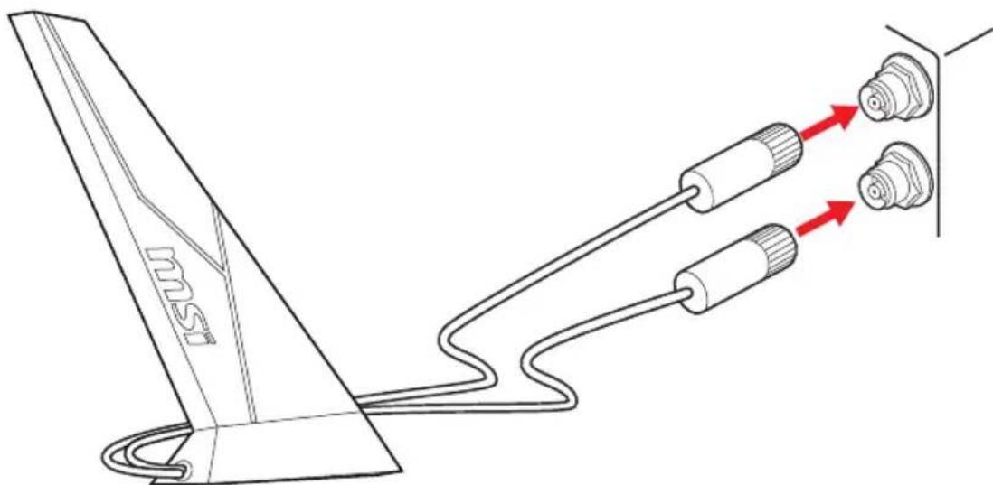
- Place the antenna as high as possible for a better signal.

Overview of Components
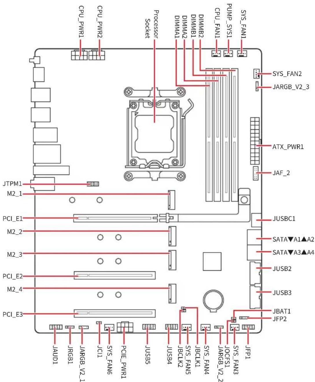
CPU Socket
The AM5 socket is a modern CPU socket designed for AMD processors. It is a key component in contemporary computing systems, providing the foundation for powerful and efficient CPUs.

Installing the CPU to the AM5 socket
The surface of the AM5 CPU has two notches and a golden triangle to assist in correctly lining up the CPU for motherboard placement. The golden triangle is the Pin 1 indicator.
To install the CPU, align the two notches on the AM5 socket with the two corresponding notches on the CPU. Please ensure that the gold triangle on the CPU serves as the PIN 1 indicator during the installation process.

Distance from the center of the CPU socket to the nearest DIMM slot.
Important
- When changing the processor, the system configuration could be cleared and reset BIOS to default values, due to the AM5 processor's architecture.
- Please ensure that the motherboard and power supply are turned off and always disconnect the power cord from the power outlet before installing or removing the CPU.
- Please retain the CPU protective cap after installing the processor. MSI will deal with Return Merchandise Authorization (RMA) requests if only the motherboard comes with the protective cap on the CPU socket.
- Whenever the CPU is not installed, always protect the CPU socket pins by covering the socket with the protective cap.
- The CPU should only fit in one orientation, so do not force it. Gently place the CPU into the socket without applying excessive pressure.
- Please handle the CPU by the edges only; avoid touching the pins or the surface of the CPU. Any damage to the pins can result in a malfunctioning CPU.
- When installing a CPU, always remember to install a CPU heatsink. A CPU heatsink is necessary to prevent overheating and maintain system stability.
- Please install the CPU cooler according to the manufacturer's instructions. Make sure it is securely a tight seal with the CPU and attached to the motherboard to ensure proper heat dissipation.
• Overheating can seriously damage the CPU and motherboard. Always make sure the cooling fans work properly to protect the CPU from overheating. Be sure to apply an even layer of thermal paste (or thermal tape) between the CPU and the heatsink to enhance heat dissipation. - This motherboard is designed to support overclocking. Before attempting to overclock, please make sure that all other system components can tolerate overclocking. Any attempt to operate beyond product specifications is not recommended. MSI® does not guarantee the damages or risks caused by inadequate operation beyond product specifications.
DDR5 DIMM Slots
The DDR5 DIMM slot is a dedicated connector designed to accommodate DDR5 (Double Data Rate 5) memory modules. It represents the latest standard in computer memory, providing enhanced data transfer speeds and efficiency.


Memory module installation recommendation


Always insert memory modules in the DIMMA2 slot first.


Important
- The DIMM slots on this motherboard only have a single latch. Please be careful when installing or removing memory modules to avoid damaging the slots.
- Align the notch on the DDR5 module with the notch on the memory slot to ensure proper orientation. Do not force the module into the slot; it should slide in easily if properly aligned.
- To ensure system stability for Dual channel mode, memory modules must be of the same type, number and density.
- Some memory modules may operate at a lower frequency than the marked value when overclocking due to the memory frequency operates dependent on its Serial Presence Detect (SPD). Go to BIOS and find the DRAM Speed to set the memory frequency if you want to operate the memory at the marked or at a higher frequency.
- It is recommended to use a more efficient memory cooling system for full DIMMs installation or overclocking.
- The stability and compatibility of installed memory module depend on installed CPU and devices when overclocking.
- Please refer to www.msi.com for more information on compatible memory.
PCI_E1\~3: PCIe Expansion Slots
PCI Express (PCIe) expansion slots are used to connect add-on cards to the motherboard. These cards can provide additional functionality to your computer, such as graphics, networking, or storage.

Important
- If you install a large and heavy graphics card, you need to use a tool such as MSI Graphics Card Bolster to support its weight to prevent deformation of the slot.
- For a single PCIe x16 expansion card installation with optimum performance, using the PCI_E1 slot is recommended.
- When adding or removing expansion cards, always turn off the power supply and unplug the power supply power cable from the power outlet. Read the expansion card’s documentation to check for any necessary additional hardware or software changes.
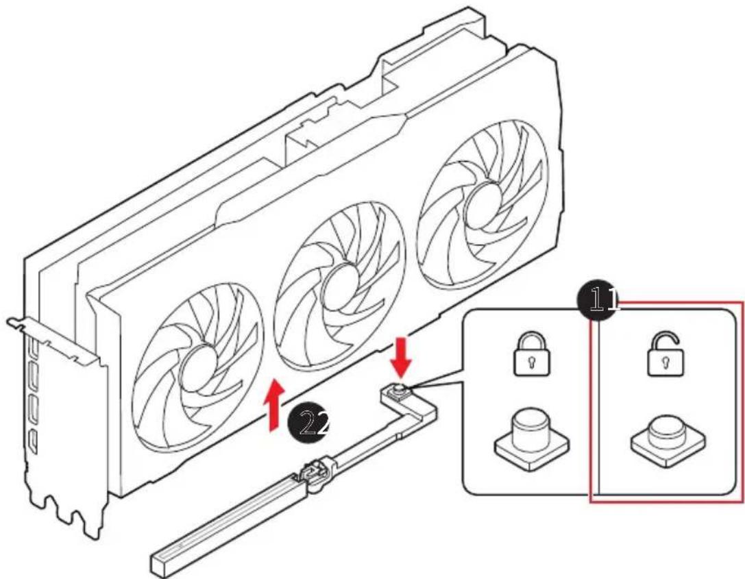
Installing a graphics card into PCI_E1 slot
- Ensure that the EZ PCIe Release Button is in the locked position. If it is unlocked, press the button to lock it.
- Insert the graphics card into the PCIe slot.

Removing a graphics card from PCI_E1 slot
-
Ensure that the EZ PCIe Release Button is in the unlocked position. If it is locked, press the button to unlock it.
-
Gently pull the graphics card out of the PCIe slot.
M2_1\~4: M.2 Slots (Key M)
The M.2 slot is a small, high-speed expansion slot on a motherboard. It can be used to connect an M.2 SSD, which is a type of solid-state drive that offers faster performance than traditional SATA SSDs.

Watch the video to learn how to Install M.2 SSD with Screwless M.2 Shield Frozr heatsink.

- https://msi.gm/S7F5D000

ortant
If your M.2 SSD equips its own heatsink, please note the following:
- Remove the M.2 plate or rubber cube in the M.2 slot before installing M.2 SSD. Do not re-install the heatsink supplied with the motherboard.
- Ensure that the M.2 SSD heatsink you use fits the size limits to prevent damage.
M.2 SSD Heatsink Size Restrictions
If you need to purchase an additional heatsink, please refer to the diagram below to confirm the M.2 installation space dimensions. Please also consider the height of the installed PCIe expansion card when determining M.2 installation space.

Installing M.2 module into M2_1 slot
- Press and hold the end button of Screwless M.2 Shield Frozr heatsink.

- Slightly lift up the end part of Screwless M.2 Shield Frozr heatsink and move it forward to uninstall the heatsink.

- If you install 22110 SSD, use the included EZ M.2 Clip II Remover to remove EZ M.2 Clip II from the 2280 screw hole. Skip this step if you install 2280 SSD.

- Insert your M.2 SSD into the M.2 slot at a 30-degree angle.
- Rotate the EZ M.2 Clip to secure the M.2 SSD, or use the EZ M.2 Clip II, which automatically locks and secures the SSD.

- Remove the protective films from the thermal pads under Screwless M.2 Shield Frozr heatsink.
- Align the notches under Screwless M.2 Shield Frozr heatsink with the tenons, and then put the heatsink back in place.
- Press the end side of Screwless M.2 Shield Frozr heatsink to lock it completely.

Removing M.2 SSD using the EZ M.2 Clip II
To remove M.2 SSD from the EZ M.2 Clip II, gently push the spring head on the top of the EZ M.2 Clip II outward while simultaneously pulling the M.2 SSD out.

Installing M.2 module into M2_2\~M2_4 slots
-
Loosen the screws of M.2 Shield Frozr heatsink.
-
Lift up the M.2 Shield Frozr heatsink and remove it.
![graph TD A["Tool 1"] --> B["Rotation Arrow 2"] B --> C["Component 1"] C --> D["Return Arrow 1"] D --> E["Return Arrow 2"] E --> F["Component 1"] F --> G["Return Arrow 1"] G --> H["Return Arrow 2"] H --> I["Return Arrow 1"] I --> J["Return Arrow 2"] J --> K["Return Arrow 1"] K --> L["Return Arrow 2"]…](/content/2026/08/1629499/images/d0ed7760840547b1d561da5d62945e2ce62c88574c9bbe9c9e26e19b05be7a7c.jpg)
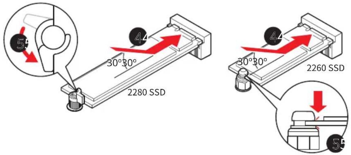
- If you install 2260 SSD, please use the included EZ M.2 Clip II Remover to install the included EZ M.2 Clip II in the screw hole. Skip this step if you install 2280 SSD.

-
Insert your M.2 SSD into the M.2 slot at a 30-degree angle.
-
Rotate the EZ M.2 Clip to secure the M.2 SSD, or use the EZ M.2 Clip II, which automatically locks and secures the SSD.
-
Remove the protective film from the thermal pad under the M.2 Shield Frozm heatsink.
-
Put the M.2 Shield Frozr heatsink back in place and secure it.
![graph TD A["Component 6"] --> B["Component 7"] B --> C["Component 7"] C --> D["Component 7"] D --> E["Component 7"] E --> F["Component 7"] F --> G["Component 7"] G --> H["Component 7"] H --> I["Component 7"] I --> J["Component 7"] J --> K["Component 7"] K --> L["Component 7"] L --> M["Component 7"]…](/content/2026/08/1629499/images/4a89fb08f272eb334323523a33111a57fe7aebf5d675bedd07e25300ce4be26b.jpg)
Removing M.2 SSD using the EZ M.2 Clip II
To remove M.2 SSD from the EZ M.2 Clip II, gently push the spring head on the top of the EZ M.2 Clip II outward while simultaneously pulling the M.2 SSD out.

SATA_A1\~A4: SATA 6Gb/s Connectors
These connectors are SATA 6Gb/s interface ports. Each connector can connect to one SATA device.
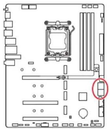

Important
- Please do not fold the SATA cable at a 90-degree angle. Data loss may result during transmission otherwise.
- SATA cables have identical plugs on either sides of the cable. However, it is recommended that the flat connector be connected to the motherboard for space saving purposes.
JAUD1: Front Audio Connector
This connector allows you to connect audio jacks on the front panel.


| Pin Signal Name Pin Signal Name | |||
| 1 MIC L 2 Ground | |||
| 3 MIC R 4 NC | |||
| 5 Head Phone R 6 MIC Detection | |||
| 7 SENSE_SEND 8 | No Pin | ||
| 9 | Head Phone L | 10 | Head Phone Detection |
JFP1, JFP2: Front Panel Connectors
The JFP1 connector controls the power on, power reset, and the LEDs on your PC case/chassis. Power Switch/ Reset Switch headers allow you to connect power button/ reset button. Power LED header connects to LED light on the PC case, and HDD LED header indicates the activity of the hard disk. The JFP2 connector is for Buzzer and Speaker. For connecting the cables from your PC case to the correct pins on the motherboard, please refer to the following images.

![graph TD A["Power LED"] -->|+ -| B["JFP1"] C["Power Switch"] -->|+ -| B B --> D["Reserved"] D --> E["Reset SwitchHDD LED"] F["Buzzer"] -->|+ -| G["JFP2"] G --> H["Speaker"]](/content/2026/08/1629499/images/3daff1745ce40fd6ee0fe8d46fe64f6b55ab41e3bd2337650c37dccbf82f9676.jpg)

Make sure to connect the Power LED and HDD LED cables to the corresponding positive and negative pins on the motherboard. Otherwise, the LEDs will not function properly.
CPU_PWR1\~2, ATX_PWR1, PCIE_PWR1: Power Connectors
These power connectors allow you to connect an ATX power supply.

CPU_PWR1\~2
| Pin Signal Name Pin Signal Name | |||
| 1 Ground 2 Ground | |||
| 3 Ground 4 Ground | |||
| 5 +12V 6 +12V | |||
| 7 +12V 8 +12V | |||
ATX_PWR1
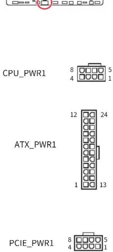
| Pin Signal Name Pin Signal Name | |||
| 1 +3.3V 2 +3.3V | |||
| 3 Ground 4 +5V | |||
| 5 Ground 6 +5V | |||
| 7 Ground 8 PWR OK | |||
| 9 5VSB 10 +12V | |||
| 11 +12V 12 +3.3V | |||
| 13 +3.3V | 14 -12V | ||
| 15 | Ground | 16 | PS-ON# |
| 17 | Ground | 18 | Ground |
| 19 | Ground | 20 Res | |
| 21 +5V 22 +5V | |||
| 23 +5V 24 | Ground | ||
PCIE_PWR1
| Pin Signal Name Pin Signal Name | ||
| 1 +12V 2 +12V | ||
| 3 +12V 4 SENS1 | ||
| 5 Ground 6 SENS0 | ||
| 7 Ground 8 Ground |

Make sure that all the power cables are securely connected to a proper ATX power supply to ensure stable operation of the motherboard.
JCI1: Chassis Intrusion Connector
This connector allows you to connect the chassis intrusion switch cable.


Normal (default)

Trigger the chassis intrusion event
Using chassis intrusion detector
- Connect the JCI1 connector to the chassis intrusion switch/ sensor on the chassis.
- Close the chassis cover.
- Go to BIOS > Security > Chassis Intrusion Configuration.
- Set Chassis Intrusion to Enabled.
- Press F10 to save and exit and then press the Enter key to select Yes.
- Once the chassis cover is opened again, a warning message will be displayed on screen when the computer is turned on.
Resetting the chassis intrusion warning
- Go to BIOS > Security > Chassis Intrusion Configuration.
- Set Chassis Intrusion to Reset.
- Press F10 to save and exit and then press the Enter key to select Yes.
JUSBC1: USB 20Gbps Type-C Front Panel Connectors
This USB connector allows you to connect to the USB Type-C® port on the front panel and supports data transfer speeds of up to 20Gbps. It features a user-friendly design that ensures proper orientation when connecting the cable.


JUSB2\~3: USB 5Gbps Connectors
These USB connectors allow you to connect to USB ports on the chassis panel and supports data transfer speeds of up to 5Gbps.


| Pin Signal Name Pin Signal Name | |||
| 1 Power 2 USB3_RX_DN | |||
| 3 USB3_RX_DP 4 Ground | |||
| 5 USB3_TX_C_DN 6 USB3_TX_C_DP | |||
| 7 Ground 8 USB2.0- | |||
| 9 USB2.0+ 10 Ground | |||
| 11 USB2.0+ 12 USB2.0- | |||
| 13 Ground 14 USB3_TX_C_DP | |||
| 15 USB3_TX_C_DN | 16 Ground | ||
| 17 USB3_RX_DP | 18 | USB3_RX_DN | |
| 19 Power 20 No Pin | |||

Note that the Power and Ground pins must be connected correctly to avoid possible damage.
JUSB4\~5: USB 2.0 Connectors
These USB connectors allow you to connect to USB ports on the chassis panel and supports data transfer speeds of up to 480Mbps.


| Pin Signal Name Pin Signal Name | |||
| 1 | VCC | 2 | VCC |
| 3 USB0-4 | USB1- | ||
| 5 USB0+ | 6 USB1+ | ||
| 7 Ground 8 Ground | |||
| 9 No | Pin 10 NC | ||

- Note that the VCC and Ground pins must be connected correctly to avoid possible damage.
- In order to recharge your iPad, iPhone and iPod through USB ports, please install MSI Center utility.
JTPM1: TPM Module Connector
This connector is designed for a Trusted Platform Module (TPM) to enable secure storage of sensitive data and perform cryptographic operations that ensure the integrity of your system.


| Pin Signal Name Pin Signal Name | |||
| 1 SPI | Power 2 SPI Chip Select | ||
| 3 | Master In Slave Out (SPI Data) | 4 | Master Out Slave In (SPI Data) |
| 5 Reserved 6 SPI Clock | |||
| 7 Ground 8 SPI Reset | |||
| 9 Reserved 10 No Pin | |||
| 11 Reserved 12 Interrupt Request | |||

The TPM module is not included and must be purchased separately.
JOC_FS1: Safe Boot Jumper
This jumper is used for Safe Boot. When this jumper is enabled, the system will boot with default settings and lower PCIe (from CPU) mode.

Normal (default) Boot with the saved BIOS settings.
Enabled Apply the BIOS default settings and lower PCIe (from CPU) mode for Safe Boot
JBAT1: Clear CMOS (Reset BIOS) Jumper
There is CMOS memory onboard that is external powered from a battery located on the motherboard to save system configuration data. If you want to clear the system configuration, set the jumpers to clear the CMOS memory.

Keep Data (default)
Keep Data (default)
Clear CMOS/Reset BIOS
Resetting BIOS to default values
- Power off the computer and unplug the power cord.
- Use a jumper cap to short JBAT1 for about 5-10 seconds.
- Remove the jumper cap from JBAT1.
- Plug the power cord and Power on the computer.
JBCLK1\~2: BCLK Frequency Jumpers
These jumpers are provided for overclocking enthusiasts to fine-tune the CPU Base Clock (BCLK). You can connect momentary switches to these jumpers for manual, real-time BCLK adjustment while the system is operating.

![graph TD A["JBCLK1 (Increase Frequency)"] --> B["JBCLK2 (Decrease Frequency)"] C["JBCLK1"] --> D["JBCLK2"] E["JBCLK2"] --> F["JBCLK1"]](/content/2026/08/1629499/images/8734dc8bd7bd90d68736440fb04953aa7d313c0ef006b0beaadd7be097f5115a.jpg)

- The overclocking results may vary depending on the installed CPU.
- Adjusting BCLK is an overclocking activity that may cause system instability or permanent damage, and it will void your product warranty.
- Ensure that your cooling system is adequate to handle the increased heat.
- If BCLK overclocking causes system instability or crashes, please clear CMOS to restore factory settings.
CPU_FAN1, PUMP_SYS1, SYS_FAN1\~6: Fan Connectors
Fan connectors can be divided into two categories: PWM Mode and DC Mode. PWM Mode fan connectors provide a constant 12V output and adjust fan speed with a speed control signal. DC Mode fan connectors control fan speed by changing voltage. Please refer to the following specification table for the fan connector mode of your motherboard.
You can control fans in BIOS> HARDWARE MONITOR panel. Enabling Smart Fan Mode will regulate fan speed based on CPU or system temperature. Disabling Smart Fan Mode will set the fan to full speed.

You can set DC or PWM in HARDWARE MONITOR panel to your fan type if your motherboard supports it. Make sure fans are working properly after switching the PWM/ DC mode.

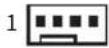

PWM Mode pin definition
| Pin Signal Name Pin Signal Name | |||
| 1 Ground 2 +12V | |||
| 3 Sense 4 Speed Control | Signal | ||
DC Mode pin definition
| Pin Signal Name Pin Signal Name | |||
| 1 Ground 2 Voltage Control | |||
| 3 Sense 4 NC | |||
Fan specifications for fan connectors
| Connector Fan mode Max. current Max. power | |||
| CPU_FAN1 | Auto mode | 2A | 24W |
| PUMP_SYS1 | PWM mode | 3A | 36W |
| SYS_FAN1~6 | Auto mode | 1A | 12W |

The auto mode fan connectors can automatically detect PWM and DC modes.
JRGB1: RGB LED connector
The JRGB connector allows you to connect the 5050 RGB LED strips 12V.


| Pin Signal Name Pin Signal Name | |||
| 1 +12V 2 G | |||
| 3 R 4 B | |||
RGB LED Strip Connection

RGB LED Fan Connection

Important
- The JRGB connector supports up to 2 meters continuous 5050 RGB LED strips (12V/G/R/B) with the maximum power rating of 3A (12V).
• Always turn off the power supply and unplug the power cord from the power outlet before installing or removing the RGB LED strip. - Please use MSI's software to control the extended LED strip.
JARGB_V2_1\~3: A-RAINBOW V2 (ARGB Gen2) LED connectors
The JARGB_V2 connectors allow you to connect the ARGB Gen2 and the ARGB-based LED strips. The JARGB_V2 connector supports up to 240 individually addressable RGB LEDs with maximum power rating of 3A (5V).

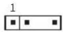
| Pin Signal Name Pin Signal Name | |||
| 1 +5V 2 Data | |||
| 3 No | Pin 4 Ground | ||
Addressable RGB LED Strip Connection

Addressable RGB LED Fan Connection


Do not connect the wrong type of LED strips. The JRGB connector and the JARGB_V2 connector provide different voltages, and connecting the ARGB 5V LED strip to the JRGB connector will result in damage to the LED strip.

Important
- If you connect the ARGB Gen1 and ARGB Gen2 LED strips into the same connector, it may cause some issues. Please do not mix the ARGB Gen1 LED and the ARGB Gen2 LED strips together.
- It is recommended that you install LED strips with the same specification to achieve the best effects.
• Always turn off the power supply and unplug the power cord from the power outlet before installing or removing the addressable RGB LED strip. - Please use MSI's software to control the extended LED strip.
JAF_2: EZ Conn-Header V2
This header allows you to connect the ARGB Gen1 and Gen2 LED strips, fans and USB 2.0 devices. It can also be used to connect MPG EZ120 ARGB fans.


| Pin Signal Name Pin Signal Name | |||
| 1 Ground 2 5V | |||
| 3 12V 4 DATA | |||
| 5 Sense 6 Ground | |||
| 7 Speed 8 N/A | |||
| 9 Ground 10 USB 2.0+ | |||
| 11 +5 VSB 12 USB 2.0- | |||
Addressable RGB LED Fan Connection
![graph LR A["JAF_2 header"] --> B["1 to 3 EZ Conn-Cable (V2)"] B --> C["USB 2.0 device"] C --> D["ARGB LED Fan"] style A fill:#f9f,stroke:#333 style D fill:#ccf,stroke:#333](/content/2026/08/1629499/images/6581e436b877c4845aa9baa2744934406599f71b005c9eebe748304dc0afe246.jpg)
MPG EZ120 ARGB Fan Connection

Important
• The Fan-JAF1 Cable is included in the packaging of MPG EZ120 ARGB.
- JAF_2 header is compatible with JAF_1 header since pins 1 to 7 carry the same signals. MPG EZ120 ARGB can be connected to the JAF_2 header.
- For more information on how to install MPG EZ120 ARGB, please refer to https://msi.gm/S5035E56.
Onboard LEDs
EZ Debug LED
These LEDs indicate the debug status of the motherboard.

| LED Color Status | |
| Red | CPU is not detected or fail |
| Yellow | DRAM is not detected or fail |
| White | GPU is not detected or fail |
| Green | Booting device is not detected or fail |
EZ Memory Detection LED
This LED indicates that the memory module's power is not detected. If any memory module loses power, this LED will light up.
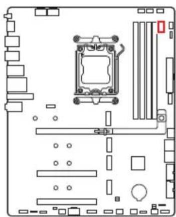
Installing OS, Drivers & MSI Center
Please download and update the latest utilities and drivers at www.msi.com
Installing Windows 11
- Power on the computer.
- Insert the Windows 11 installation disc/USB into your computer.
- Press the Restart button on the computer case.
- Press F11 key during the computer POST (Power-On Self Test) to get into Boot Menu.
- Select the Windows 11 installation disc/USB from the Boot Menu.
- Press any key if screen shows Press any key to boot from CD or DVD... message. If not, please skip this step.
- Follow the instructions on the screen to install Windows 11.
Installing Drivers with MSI Driver Utility Installer

- Some new network chips have not been natively supported by Windows 11. It is recommended that the LAN driver be installed before installing drivers with MSI Driver Utility Installer. Please refer to www.msi.com to install the LAN driver for your motherboard.
-
The MSI Driver Utility Installer will only pop up once. If you cancel or close it during the process, please refer to the Live Update chapter of the MSI Center manual to install the drivers. You can also go to www.msi.com to search your motherboard and download the drivers.
• MSI Driver Utility Installer needs to be installed over the internet. -
Start up your computer in Windows 11.
- Select Start > Settings > Windows Update, and then select Check for updates.
- MSI Driver Utility Installer will pop up automatically.

- Select the I have read and agree to the MSI Terms of Use check box, and then click Next.

- Check the Select All checkbox in the lower-left corner and click Install to install MSI Center and drivers. The installation progress will be shown at the bottom.

- Once the progress has completed, click Finish.
MSI Center
MSI Center is an application that helps you easily optimize game settings and smoothly use content creation softwares. It also allows you to control and synchronize LED light effects on PCs and other MSI products. With MSI Center, you can customize ideal modes, monitor system performance, and adjust fan speed.
MSI Center User Guide

If you would like to know more information about MSI Center, please refer to https://msi.gm/S391169E
or scan the QR code to access.

Functions may vary depending on the product you have.
UEFI BIOS
MSI UEFI BIOS is compatible with UEFI (Unified Extensible Firmware Interface) architecture. UEFI has many new functions and advantages that traditional BIOS cannot achieve, and it will completely replace BIOS in the future. The MSI UEFI BIOS uses UEFI as the default boot mode to take full advantage of the new chipset's capabilities. However, it still has a CSM (Compatibility Support Module) mode to be compatible with older devices. That allows you to replace legacy devices with UEFI compatible devices during the transition.

The term BIOS in this user guide refers to UEFI unless otherwise noted.
UEFI advantages
- Fast booting - UEFI can directly boot the operating system and save the BIOS self-test process. And also eliminates the time to switch to CSM mode during POST.
• Supports for hard drive partitions larger than 2 TB.
• Supports more than 4 primary partitions with a GUID Partition Table (GPT).
• Supports unlimited number of partitions. - Supports full capabilities of new devices - new devices may not provide backward compatibility.
- Supports secure startup - UEFI can check the validity of the operating system to ensure that no malware tampers with the startup process.
Incompatible UEFI cases
- 32-bit Windows operating system - this motherboard supports only Windows 11 64-bit operating system.
- Older graphics card - the system will detect your graphics card. If you use older graphics cards, it may display a warning message There is no GOP (Graphics Output protocol) support detected in this graphics card.

We recommend that you replace it with a graphics card supporting GOP/UEFI or use CPU with integrated graphics for having normal function.
BIOS Setup
The default settings offer the optimal performance for system stability in normal conditions. You should always keep the default settings to avoid possible system damage or failure booting unless you are familiar with BIOS.

- It’s not recommended to update BIOS when system has no issue.
- BIOS items are continuously updated for better system performance. Therefore, the description may be slightly different from the latest BIOS and should be for reference only. You could also refer to the HELP information panel in BIOS.
- The BIOS screens, options and settings will vary depending on the products you have.
BIOS User Guide

If you’d like to know more instructions on setting up the BIOS, please refer to https://msi.gm/S53FE767
or scan the QR code to access.

The appearance of the BIOS user guide may differ based on your motherboard model. Please consult your motherboard's BIOS for specific settings and options.
Entering BIOS Setup
Press Delete key, when the Press DEL key to enter Setup Menu, F11 to enter Boot Menu message appears on the screen during the boot process.
Function key
+/-: Increase / decrease the value
Enter: Select the item
ESC: Exit
Tab: Next selection
Ctrl+F: Enter Search menu
F1: General Help list
F2: Add/ Remove a favorite item
F3: Enter Favorites menu
F4: Enter CPU core center & memory center information menu
F5: Enter Hardware Monitor menu
F6: Load optimized defaults
F7: Switch between Advanced mode and EZ mode
F8: Load Overclocking Profile
F9: Save Overclocking Profile
F10: Save Change and Reset*
F12: Take a screenshot and save it to USB flash drive (FAT/ FAT32 format only).
* Pressing F10 displays a confirmation message summarizing your changes. Select Yes or No to confirm.
How to find the BIOS version?
After entering the BIOS, find the BIOS version in the information box.

Resetting BIOS
If you encounter certain issues with your computer, restoring the default BIOS settings might help. You can reset the BIOS settings using the following methods:
- Enter the BIOS setup and press F6 to load the optimized defaults.
- Use the Clear CMOS jumper on the motherboard to reset the BIOS.
- If your motherboard has a Clear CMOS button on the rear I/O panel, press it to reset the BIOS.

Ensure the computer is powered off before clearing the CMOS data. For more details, refer to the Clear CMOS jumper/button section in the manual.
Updating BIOS
Updating BIOS with M-FLASH
Before starting the M-Flash process, make sure you have:
- A USB flash drive with a capacity of 32GB or less that is formatted to FAT32.

M-Flash only supports FAT32 format, and the USB flash drive should not exceed 32GB.
- A computer with internet access.
Please follow the steps below to update BIOS:
- Download the latest BIOS file from the MSI website that matches your motherboard model, and save it to the USB flash drive.
- If your motherboard has a Multi-BIOS switch, switch to the target BIOS ROM.
- Insert the USB flash drive into your motherboard's USB port.
-
Enter flash mode by either:
-
Rebooting and pressing Ctrl + F5 during POST, then clicking Yes to reboot the system.
-
Rebooting and pressing Del during POST to enter BIOS, then clicking the M-FLASH button and clicking Yes to reboot.
-
Select a BIOS file from the M-FLASH File menu and press Enter.
- When prompted by a File Check message, click Yes to start the BIOS update.
Once the update reaches 100%, the system will reboot automatically.
Updating BIOS with MSI Center
Before updating:
- Ensure the LAN driver is installed, and the internet connection is working properly.
- Close all other applications before updating the BIOS.
To update BIOS:
- Install and launch MSI Center, then go to Support page.
- Select Live Update and click on Advance button.
- Select the BIOS file and click on Install button.
- The installation reminder will appear, then click the Install button.
The system will automatically restart to update the BIOS. Once the flashing process is complete, the system will restart.
Updating BIOS with Flash BIOS Button
- Download the latest BIOS file from the MSI website that matches your motherboard model.
- Rename the BIOS file to MSI.ROM, and save it to the root directory of a USB flash device.
- Connect the power supply to CPU_PWR1 and ATX_PWR1. (You don't need to install the CPU and memory.)
- Plug the USB flash device with the MSI.ROM file into the Flash BIOS Port on the rear I/O panel.
- Press the Flash BIOS Button to start flashing the BIOS. The LED will start flashing to indicate the process has begun.
The LED will turn off when the process is complete.
Block Diagram
MAG B850 TOMAHAWK MAX WIFI II
![graph TD A["CPU"] -->|PCI_E1\nPCIe 5.0x16| B["PCIe x4"] A -->|USB3.2 Gen2 10Gbps\n(Rear Type-C *3/Type-A*1)| C["PCIe x4"] A -->|USB2\n(Rear Type-A)| D["GL850"] A -->|M.2_1/2\nGEN5 x4 (PCIe Only)| E["PCIe x4"] A -->|HDMI™ 2.1 FRL\n(8K@60Hz)| F["SIO 6687"] A -->|DDR5\nDIMM A1/A2\nDIMM B1/B2| G["PCIe x…](/content/2026/08/1629499/images/3302bd920dbdcecf6db535dffe7973066e81fd888d32e248501787055884217e.jpg)
Regulatory Notices
FCC-B Radio Frequency Interference Statement
This equipment has been tested and found to comply with the limits for a Class B digital device, pursuant to part 15 of the FCC rules. These limits are designed to provide reasonable protection against harmful interference in a residential installation. This equipment generates, uses and radiates radio frequency energy, and, if not installed and used in accordance with the instructions, may cause harmful interference to radio communications. However, there is no guarantee that interference will not occur in a particular installation. If this equipment does cause harmful interference to radio or television reception, which can be determined by turning the equipment off and on, the user is encouraged to try to correct the interference by one or more of the following measures:

- Reorient or relocate the receiving antenna.
- Increase the separation between the equipment and receiver.
- Connect the equipment into an outlet on a circuit different from that to which the receiver is connected.
NOTE
- The changes or modifications not expressly approved by the party responsible for compliance could void the user’s authority to operate the equipment.
- Shield interface cables and AC power cord, if any, must be used in order to comply with the emission limits.
FCC Conditions
This device complies with part 15 of the FCC Rules. Operation is subject to the following two conditions:
• This device may not cause harmful interference.
- This device must accept any interference received, including interference that may cause undesired operation.
MSI Computer Corp.
901 Canada Court, City of Industry, CA 91748, USA
(626)913-0828
www.msi.com
CE Conformity
Products bearing the CE marking comply with one or more of the following EU Directives as may be applicable:

- RED 2014/53/EU
• Low Voltage Directive 2014/35/EU
• EMC Directive 2014/30/EU
• RoHS Directive 2011/65/EU
- Implementing measure Directive 2009/125/EC of ESPR Regulation (EU) 2024/1781
Compliance with these directives is assessed using applicable European Harmonized Standards.
For any support regarding the EU General Product Safety Regulation (GPSR), please contact MSI Computer Europe B.V. via https://msi.gm/gpsr Churchillaan 202, 5705 BK Helmond, the Netherlands.
Products with Radio Functionality (EMF)
This product incorporates a radio transmitting and receiving device. For computers in normal use, a separation distance of 20 cm ensures that radio frequency exposure levels comply with EU requirements. Products designed to be operated at closer proximities, such as tablet computers, comply with applicable EU requirements in typical operating positions. Products can be operated without maintaining a separation distance unless otherwise indicated in instructions specific to the product.
Restrictions for Products with Radio Functionality

WLAN 5150-5350 MHz:
The WiFi operating in the band 5150-5350 MHz shall be restricted to indoor use in the European Union.
WLAN 7:
a. Low Power Indoor (LPI) Wi-Fi 5.945-6.425 GHz devices:
The device is restricted to indoor use only when operating in the 5945 to 6425 MHz frequency range in the European Union.
b. Very Low Power (VLP) Wi-Fi 5.945-6.425 GHz devices (portable devices):
The device is not permitted to be used on Unmanned Aircraft Systems (UAS) when operating in the 5945 to 6425 MHz frequency range in the European Union.
Wireless Radio Use
This device is restricted to indoor use when operating in the 2.4GHz, 5GHz, 6GHz frequency band.
Compliance Statement of Innovation, Science and Economic Development Canada (ISED)
This device complies with with Innovation, Science and Economic Development Canada’s licence-exempt RSS(s). Operation is subject to the following two conditions:
(1) this device may not cause interference, and (2) this device must accept any interference, including interference that may cause undesired operation of the device.
Operation in the band 5150-5250 MHz is only for indoor use to reduce the potential for harmful interference to co-channel mobile satellite systems.
CAN ICES-003(B)/NMB-003(B)
Australia and New Zealand notice
This equipment incorporates a radio transmitting and receiving device. In normal use, a separation distance of 20 cm ensures that radio frequency exposure levels comply with the Australian and New Zealand Standards.
クラスB情報技術装置
Batteries, battery packs, and accumulators should not be disposed of as unsorted household waste. Please use the public collection system to return, recycle, or treat them in compliance with the local regulations.
BSMI:

廢電池請回收
For better environmental protection, waste batteries should be collected separately for recycling or special disposal.
California, USA:

The button cell battery may contain perchlorate material and requires special handling when recycled or disposed of in California.
For further information please visit:
https://dtsc.ca.gov/perchlorate/
WARNING
- INGESTION HAZARD: This product contains a button cell or coin battery.
- DEATH or serious injury can occur if ingested.
- A swallowed button cell or coin battery can cause Internal Chemical Burns in as little as 2 hours.
- KEEP new and used batteries OUT OF REACH OF CHILDREN
- Seek immediate medical attention if a battery is suspected to be swallowed or inserted inside any part of the body.

- Remove and immediately recycle or dispose of used batteries according to local regulations and keep away from children. Do NOT dispose of batteries in household trash or incinerate.
- Even used batteries may cause severe injury or death. Call a local poison control center for treatment information.
- Battery type: CR2032
- Battery voltage: 3V
• Non-rechargeable batteries are not to be recharged. - Do not force discharge, recharge, disassemble, heat above (manufacturer’s specified temperature rating) or incinerate. Doing so may result in injury due to venting, leakage or explosion resulting in chemical burns.
- This product contains an irreplaceable battery.
- This icon indicates that a swallowed button battery can cause serious injury or death. Please keep batteries out of sight or reach of children.
Chemical Substances Information
In compliance with chemical substances regulations, such as the EU REACH Regulation (Regulation EC No. 1907/2006 of the European Parliament and the Council), MSI provides the information of chemical substances in products at:
https://csr.msi.com/global/index
Environmental Policy
- The product has been designed to enable proper reuse of parts and recycling and should not be thrown away at its end of life.
- Users should contact the local authorized point of collection for recycling and disposing of their end-of-life products.
- Visit the MSI website https://csr.msi.com/global/pevn_ewaste and locate a nearby distributor for further recycling information.
- Please visit https://us.msi.com/page/recycling for information regarding the recycling of your product in the US.

WEEE (Waste Electrical and Electronic Equipment) Statement

European Union: This symbol on the product indicates that this product cannot be discarded as municipal waste. Instead, it is your responsibility to dispose of your waste electrical and electronic equipment by handing it over to a designated collection point for recycling. For more information about where you can drop off your waste equipment for recycling, please contact your local city office, your household waste disposal service or the shop where you purchased the product.
日本JIS C 0950材質宣言
This product complies with the “India E-waste (Management and Handling) Rule 2011” and prohibits use of lead, mercury, hexavalent chromium, polybrominated biphenyls or polybrominated diphenyl ethers in concentrations exceeding 0.1 weight % and 0.01 weight % for cadmium, except for the exemptions set in Schedule 2 of the Rule.
Copyright and Trademarks Notice
msi
MSI
微星
微星科技
MICRO-STAR INTERNATIONAL

Copyright © Micro-Star Int’ I Co., Ltd. All rights reserved. The MSI logo used is a registered trademark of Micro-Star Int’ I Co., Ltd. All other marks and names mentioned may be trademarks of their respective owners. No warranty as to accuracy or completeness is expressed or implied. MSI reserves the right to make changes to this document without prior notice.
HDMI™
HIGH-DEFINITION MULTIMEDIA INTERFACE
The terms HDMI™, HDMI™ High-Definition Multimedia Interface, HDMI™ Trade dress and the HDMI™ Logos are trademarks or registered trademarks of HDMI™ Licensing Administrator, Inc.
Technical Support
If a problem arises with your system and no solution can be obtained from the user guide, please contact your place of purchase or local distributor. Alternatively, please try the following help resources for further guidance.
- Visit the MSI website for technical guide, BIOS updates, driver updates, and other information: https://www.msi.com/support/
• Register your product at: http://register.msi.com
Revision History
• Version 1.0, 2026/02, first release.

- UEFI BIOS
- BLOCK DIAGRAM
- REGULATORY NOTICES......I
- QUICK START
- PREPARING TOOLS AND COMPONENTS
- SAFETY INFORMATION
- CASE STAND-OFF NOTIFICATION
- AVOID COLLISION NOTIFICATION
- INSTALLING A PROCESSOR
- INSTALLING DDR5 MEMORY
- CONNECTING THE FRONT PANEL HEADER
- CONNECTING THE POWER CONNECTORS
- INSTALLING SATA DRIVES
- INSTALLING A GRAPHICS CARD
- SPECIAL FEATURES
- MSI CENTER
- EZ DIY
- THERMAL FEATURES
- PERFORMANCE
- AUDIO
- RGB SUPPORT
- BIOS
- PACKAGE CONTENTS
- BOARD
- DOCUMENTATION
- CABLES
- ACCESSORIES
- LAN PORT LED STATUS TABLE
- AUDIO JACKS CONNECTION
- INSTALLING ANTENNA
- OVERVIEW OF COMPONENTS
- CPU SOCKET
- INSTALLING THE CPU TO THE AM5 SOCKET
- IMPORTANT
- DDR5 DIMM SLOTS
- PCI_E1\~3: PCIE EXPANSION SLOTS
- INSTALLING A GRAPHICS CARD INTO PCI_E1 SLOT
- REMOVING A GRAPHICS CARD FROM PCI_E1 SLOT
- M2_1\~4: M.2 SLOTS (KEY M)
- ORTANT
- M.2 SSD HEATSINK SIZE RESTRICTIONS
- INSTALLING M.2 MODULE INTO M2_1 SLOT
- REMOVING M.2 SSD USING THE EZ M.2 CLIP II
- INSTALLING M.2 MODULE INTO M2_2\~M2_4 SLOTS
- SATA_A1\~A4: SATA 6GB/S CONNECTORS
- JAUD1: FRONT AUDIO CONNECTOR
- JFP1, JFP2: FRONT PANEL CONNECTORS
- CPU_PWR1\~2, ATX_PWR1, PCIE_PWR1: POWER CONNECTORS
- JCI1: CHASSIS INTRUSION CONNECTOR
- USING CHASSIS INTRUSION DETECTOR
- RESETTING THE CHASSIS INTRUSION WARNING
- JUSBC1: USB 20GBPS TYPE-C FRONT PANEL CONNECTORS
- JUSB2\~3: USB 5GBPS CONNECTORS
- JUSB4\~5: USB 2.0 CONNECTORS
- JTPM1: TPM MODULE CONNECTOR
- JOC_FS1: SAFE BOOT JUMPER
- JBAT1: CLEAR CMOS (RESET BIOS) JUMPER
- RESETTING BIOS TO DEFAULT VALUES
- JBCLK1\~2: BCLK FREQUENCY JUMPERS
- CPU_FAN1, PUMP_SYS1, SYS_FAN1\~6: FAN CONNECTORS
- JRGB1: RGB LED CONNECTOR
- JARGB_V2_1\~3: A-RAINBOW V2 (ARGB GEN2) LED CONNECTORS
- ADDRESSABLE RGB LED STRIP CONNECTION
- ADDRESSABLE RGB LED FAN CONNECTION
- JAF_2: EZ CONN-HEADER V
- ONBOARD LEDS
- EZ DEBUG LED
- EZ MEMORY DETECTION LED
- INSTALLING OS, DRIVERS & MSI CENTER
- INSTALLING WINDOWS
- INSTALLING DRIVERS WITH MSI DRIVER UTILITY INSTALLER
- MSI CENTER USER GUIDE
- UEFI ADVANTAGES
- INCOMPATIBLE UEFI CASES
- BIOS SETUP
- BIOS USER GUIDE
- ENTERING BIOS SETUP
- FUNCTION KEY
- HOW TO FIND THE BIOS VERSION
- RESETTING BIOS
- UPDATING BIOS
- UPDATING BIOS WITH M-FLASH
- UPDATING BIOS WITH MSI CENTER
- BEFORE UPDATING
- TO UPDATE BIOS
- UPDATING BIOS WITH FLASH BIOS BUTTON
- REGULATORY NOTICES
- FCC-B RADIO FREQUENCY INTERFERENCE STATEMENT
- NOTE
- FCC CONDITIONS
- MSI COMPUTER CORP
- CE CONFORMITY
- PRODUCTS WITH RADIO FUNCTIONALITY (EMF)
- RESTRICTIONS FOR PRODUCTS WITH RADIO FUNCTIONALITY
- WLAN 5150-5350 MHZ
- WLAN
- WIRELESS RADIO USE
- COMPLIANCE STATEMENT OF INNOVATION, SCIENCE AND ECONOMIC DEVELOPMENT CANADA (ISED)
- AUSTRALIA AND NEW ZEALAND NOTICE
- クラスB情報技術装置
- BSMI
- CALIFORNIA, USA
- WARNING
- CHEMICAL SUBSTANCES INFORMATION
- ENVIRONMENTAL POLICY
- WEEE (WASTE ELECTRICAL AND ELECTRONIC EQUIPMENT) STATEMENT
- 日本JIS C 0950材質宣言
- COPYRIGHT AND TRADEMARKS NOTICE
- MSI
- 微星
- 微星科技
- HDMI™
- TECHNICAL SUPPORT
- REVISION HISTORY
Brand : MSI
Model : MAG B850 TOMAHAWK MAX WIFI II
Category : Motherboard