
DAP-E9560 - Access Point D-LINK - Free user manual and instructions
Find the device manual for free DAP-E9560 D-LINK in PDF.



| Product Type | Ceiling Mount Access Point |
| Brand | D-Link |
| Model | DAP-E9560 |
| Wireless Standards | IEEE 802.11be, 802.11ax, 802.11ac, 802.11n, 802.11g, 802.11a |
| Frequency Bands | 2.4 GHz, 5 GHz, 6 GHz |
| Antenna Type | 2 x 3.3 dBi (2.4 GHz), 2 x 4.8 dBi (5 GHz), 2 x 4.6 dBi (6 GHz) |
| Ports | 1 x 10G LAN (PoE), 1 x 2.5G LAN, 1 x RJ45 Console |
| Power Input | 802.3bt PoE or 20V/2.25A USB Type-C (adapter not included) |
| Max Power Consumption | 27.756W |
| Security | WPA/WPA2/WPA3 Personal & Enterprise, WEP 64/128-bit |
| Management | Web GUI (HTTP/HTTPS), CLI (Telnet/SSH), Nuclias Connect/Controller |
| Multi-SSID | Up to 8 SSIDs per radio (24 total) |
| VLAN Support | Yes, IEEE 802.1Q VLAN tagging |
| Captive Portal | Yes (Web Redirection, Username/Password, Passcode, Remote RADIUS, LDAP, POP3) |
| DHCP Server | Built-in with dynamic and static IP pools |
| Dimensions (L x W x H) | 223.04 x 223.04 x 46.7 mm |
| Operating Temperature | 0°C to 40°C |
| Storage Temperature | -20°C to 65°C |
| Humidity | Operating: 10%–90% non-condensing; Storage: 5%–95% non-condensing |
| Certifications | FCC, CE, IC, LVD |
| Warranty | Limited Lifetime Warranty |
| Cleaning & Maintenance | Clean the exterior with a dry, lint-free cloth. Do not use liquid cleaners or aerosols. No regular maintenance required. |
| Repairability & Spare Parts | No user-serviceable parts inside. For repair or replacement parts, contact D-Link technical support. |
| Package Contents | DAP-E9560, mounting brackets, ceiling brackets, Quick Start Guide |
Frequently Asked Questions - DAP-E9560 D-LINK
User questions about DAP-E9560 D-LINK
0 question about this device. Answer the ones you know or ask your own.
Ask a new question about this device
Download the instructions for your Access Point in PDF format for free! Find your manual DAP-E9560 - D-LINK and take your electronic device back in hand. On this page are published all the documents necessary for the use of your device. DAP-E9560 by D-LINK.
USER MANUAL DAP-E9560 D-LINK
Package Contents....6
System Requirements....6
Hardware Overview......7
LEDs....7
Connections 7
Basic Installation 8
Hardware Setup 8
Configure the access point....8
Setup Wizard 9
Web User Interface ....10
Wireless 11
Access Point Mode 11
WDS with AP Mode....13
WDS Mode 15
Wireless Security 17
Wired Equivalent Privacy (WEP) 17
Wi-Fi Protected Access (WPA / WPA2 / WPA3) ....18
LAN 20
IPv6 21
Advanced Settings....22
Performance....23
Wireless Resource 25
Multi-SSID....27
VLAN....29
VLAN List....29
Port List....30
Add/Edit VLAN 31
PVID Settings....32
Intrusion....33
Schedule 34
Internal RADIUS Server....35
ARP Spoofing Prevention 36
Bandwidth Optimization ....37
Captive Portal....39
Authentication Settings-Web Redirection Only 39
Authentication Settings-Username/Password..41
Authentication Settings- Passcode ....43
Authentication Settings- Remote RADIUS......46
Authentication Settings- LDAP 48
Authentication Settings- POP3....50
Login Page Upload 52
MAC Bypass....53
DHCP Server 54
Dynamic Pool Settings....54
Static Pool Setting 55
Current IP Mapping List....57
Filters....58
Wireless MAC ACL....58
Table of Contents
| WLAN Partition | 59 |
| IP Filter Settings | 60 |
| Traffic Control | 61 |
| Uplink/Downlink Setting | 61 |
| QoS | 62 |
| Traffic Manager | 63 |
| Status | 64 |
| Device Information | 65 |
| Client Information | 66 |
| WDS Information Page | 67 |
| Channel Analyze | 68 |
| Statistics | 69 |
| Ethernet Traffic Statistics | 69 |
| WLAN Traffic Statistics | 70 |
| Log | 71 |
| View Log | 71 |
| Log Settings | 72 |
| Maintenance Section | 74 |
| Administration | 75 |
| Limit Administrator | 75 |
| System Name Settings | 76 |
| Login Settings | 76 |
| Console Settings | 76 |
| Ping Control Setting | 77 |
| LED Settings | 77 |
| DDP Setting | 77 |
| Country Setting | 77 |
| Nuclias Connect Settings | 78 |
| Firmware and SSL Upload | 79 |
| Configuration File Upload | 80 |
| Time and Date Settings | 81 |
| Configuration and System | 82 |
| System Settings | 83 |
| Help | 84 |
Technical Specifications....85
Antenna Pattern 86
Regulatory Statements 88
Nuclias Connect Controller Introduction
Nuclias Network Controller is D-Link's centralized management solution for business networks. Nuclias Network Controller makes it easier to analyze, automate, configure, optimize, scale, and secure your network — delivering the convenience of an Enterprise-wide management solution, at an SMB price. Nuclias Network Controller gives you the financial and technical flexibility to expand from a medium-sized network to a larger one, while retaining a robust and centralized management system. And with its intuitive Graphical User Interface (GUI), a wealth of enhanced AP features, and a setup wizard that supports multiple languages, Nuclias Network Controller minimizes the hassle of deployment, configuration, and administration tasks.
The DNH-1000/3000 Nuclias Network Controller is a hardware controller with pre-loaded software. It is designed to support small-to-middle business or enterprise environments by providing network dministrators with the capability to manage D-Link DAP series access points and switches through a single platform. The Nuclias Network Controller can currently manage up to 500(DNH-1000)/1500(DNH-3000) devices per unit, with the potential to extend support to other Nuclias Network Controller products in future firmware updates.
Nuclias Network Controller supports multi-tenancy, so network administrators can grant localized management authority for local networks. In addition, because APs can support 8 SSIDs per radio (16 SSIDs per dual band APs), administrators have the option of using one SSID to create a guest network for visitors.
Nuclias Network Controller provides direct AP discovery and provisioning when it shares the same Layer-2/Layer-3 network with a given AP, allowing users to find APs and import profiles with minimum effort, which can be applied as needed to groups or individual APs for even more effective configuration.
Since Nuclias Network Controller operates transparently on the network, an AP can be deployed anywhere in an NAT environment. Admins can provide and manage a variety of distributed deployments, including settings and admin account configuration for each deployment.
Nuclias Network Controller allows for multiple user authentications while enabling specific access control configurations for each SSID, giving admins the option of configuring separate internal networks for different subnets, while enabling more advanced Value-Added Services, such as Captive Portal or Wi-Fi Hotspot.
Nuclias Connect Key Features
- Searchable Event Log and Change Log
- License-Free Access Points
• Traffic Reporting & Analytics - Authentication via Customizable Captive Portal, 802.1x and RADIUS Server, POP3, LDAP
- Remote Config. & Batch Config.
- Multilingual Support
- Intuitive Interface
• Multi-Tenant & Role-Based Administration
• Front-Desk Ticket Management
For more information on how to use Nuclias Connect with the DAP-E9560, please refer to the Nuclias Connect User Guide.
Package Contents
• DAP-E9560 Ceiling Mount Access Point
- Mounting Brackets
- Ceiling Brackets
- Quick Start Guide
Note:
- No PSU supplied. To power the units use a D-Link 802.3bt PoE switch.
- Supports 802.3at power input. In this mode, the DAP-E9560 will disable the 2.5G Ethernet port and limit the 10G Ethernet port speed to 2.5G. However, it does not accept 802.3af power input mode.
System Requirements
- Computers with Windows®, Macintosh®, or Linux-based operating systems with an installed Ethernet Adapter
- Microsoft Edge, Safari 7, Firefox 28, or Google Chrome 33 and above (for configuration)
Hardware Overview
LEDs Connections


| 1 Power/Status | Solid Red Indicates the access point has malfunctioned. | |
| Blinking Red This LED will blink during boot-up. | ||
| Solid Green | Indicates that the DAP-E9560 is working properly. | |
| 2 Console Port RJ45 console port for debug. | |
| 3 LAN Port Connect to your network with an Ethernet cable. | |
| 4 LAN (PoE) Port | Connect to a Power over Ethernet (PoE) switch or router via an Ethernet cable. |
| 5 Power Receptor | Connect the supplied power adapter. (*Note: no longer used, replaced by PoE). |
Basic Installation Hardware Setup
To power on the DAP-E9560, you can use ONE of the following methods:
- Plug one end of your Ethernet cable into the LAN(PoE) port of the DAP-E9560, and the other end into a port on a 802.3at PoE switch.
- Purchase a DPE-301GI PoE injector separately if you need to connect the access point without a 802.3at PoE Switch.
Configure the access point
![graph TD A["DAP-E9560"] --> B["802.3b PoE Switch"] B --> C["Computer"]](/content/2026/08/1629436/images/a184abdecf8f0516a249d6171aa1bf38a456feffb8ebed3c6e33c91b60f5715a.jpg)
To set up and manage the DAP-E9560, use one of the following methods:
Connect the access point and your computer to the same PoE switch. Manage the access point from the computer.
Enter https://dape9560.local in the address field of your browser.
Log in to the Administration Web pages. The default login information is:
Username: admin
Password: admin
Setup Wizard
The first login instance displays the System Settings window which requires a change in password. Additional settings include the System Time and System Country functions.
After logging in to the user interface, fill in the New Password and Confirm New Password fields.
In the System Time function, select Using Network Time Protocol (NTP) or Manually to define the system time. If required, click the Daylight Saving Offset drop-down menu and select the value (minutes).
- Setting NTP System Time: Before trying to configure NTP check, perform a ping test with the NTP server. In the NTP Server field, enter the NTP server to use. Then click the Time Zone drop-down menu and select the appropriate time zone.
- Setting System Time Manually: From the System Date drop-down menu, select the Year, Month, and Day along with the Hour and Minutes appropriate for the AP.
- Enable Daylight Saving: Click the radio button to enable the daylight savings time (DST) function. Set the DST start (24 hours) and end (24 hours) time by clicking on the drop-down menus and setting the Month, Week, Day, Hour, and Minute of the DST starting days.
Once the settings are configured, click Update button to accept the configuration and proceed to the main interface menu page.

Web User Interface
The DAP-E9560 supports an elaborate web user interface where the user can configure and monitor the device. Launch a web browser, type https://dape9560.local in the address field and then press Enter to login. Most of the configurable settings are located in the left menu of the web GUI which contains sections called Basic Settings, Advanced Settings and Status.

Wireless
On the wireless settings page, you can set up the basic wireless configuration for the access point. The user can choose from 4 different wireless modes:
Access Point - Used to create a wireless LAN
WDS with AP - Used to connect multiple wireless networks while still functioning as a wireless access point
WDS - Used to connect multiple wireless networks
Access Point Mode
Wireless Band: Select 2.4 GHz or 5 GHz or 6 GHz from the drop-down menu.
Note: 2.4GHz, 5GHz and 6GHz bands should be configured individually with the following settings, each of which can have a different SSID, channel, authentication, etc.
Mode: Select Access Point from the drop-down menu.
Network Name (SSID): Service Set Identifier (SSID) is the name designated for a specific wireless local area network (WLAN). The SSID's factory default setting is dlink. The SSID can be easily changed to connect to an existing wireless network or to establish a new wireless network. The SSID can be up to 32 characters and is case-sensitive.
SSID Visibility: Select Enable to broadcast the SSID across the network, thus making it visible to all network users. Select Disable to hide the SSID from the network.
Auto Channel Selection: This feature when enabled automatically selects the channel that provides the best wireless performance. The channel selection process only occurs when the AP is booting up. To manually select a channel, set this option to Disable and select a channel from the drop-down menu.

Channel: To change the channel, first toggle the Auto Channel Selection setting to Disable, and then use the drop-down menu to make the desired selection.
Note: The wireless adapters will automatically scan and match the wireless settings.
Channel Width: Allows you to select the channel width you would like to operate in 2.4GHz, 5GHz and 6GHz. Use the drop-down menu to choose 20 MHz or Auto 20/40 MHz or Auto 20/40/80 MHz or Auto 20/40/80/160 MHz or Auto 20/40/80/160/320 MHz.
Authentication: Use the drop-down menu to choose Open System, Enhanced Open, Enhanced Open + Open, WPA-Personal, WPA-Enterprise, or 802.1x.
- Select Open System, Enhanced Open, Enhanced Open or Open, to communicate the key across the network (WEP).
- Select WPA-Personal to secure your network using a password and dynamic key changes. No RADIUS server is required.
- Select WPA-Enterprise to secure your network with the inclusion of a RADIUS server.
- Select 802.1X if your network is using port-based Network Access Control.
Note: 1. The default Open System authentication allows wireless connection without requiring user authentication. It is highly recommended that you encrypt your network using one of the security methods other than the default setting.
- Two SSIDs will be occupied when using Enhanced Open + Open
WDS with AP Mode
Wireless Band: Select 2.4GHz or 5GHz or 6GHz from the drop-down menu.
Mode: WDS with AP mode is selected from the drop-down menu.
Network Name (SSID): Service Set Identifier (SSID) is the name designated for a specific wireless local area network (WLAN). The SSID's factory default setting is dlink. The SSID can be easily changed to connect to an existing wireless network or to establish a new wireless network.
Auto Channel Selection: Enabling this feature automatically selects the channel that will provide the best wireless performance. This feature is not supported in WDS with AP mode. The channel selection process only occurs when the AP is booting up.
Channel: All devices on the network must share the same channel. To change the channel, use the drop-down menu to make the desired selection. (Note: The wireless adapters will automatically scan and match the wireless settings.)
Note: The wireless adapters will automatically scan and match the wireless settings.
Channel Width: Allows you to select the channel width you would like to operate in 2.4GHz and 5GHz. Use the dropdown menu to choose 20 MHz or Auto 20/40 MHz or Auto 20/40/80 MHz.

AP MAC Address: Enter the MAC addresses of the APs on your network that will serve as bridges to wirelessly connect multiple networks.
Site Survey: Click on the Scan button to search for available wireless networks, then click on the available network that you want to connect with.
Authentication: Use the drop-down menu to choose Open System or WPA-Personal.
- Select Open System to communicate the key across the network.
- Select WPA-Personal to secure your network using a password and dynamic key changes. No RADIUS server is required.
Note: It is highly recommended that you use WPA-Personal to encrypt your network.
WDS Mode
Wireless Band: Select 2.4GHz or 5GHz or 6GHz from the drop-down menu.
Mode: WDS is selected from the drop-down menu.
Network Name (SSID): Service Set Identifier (SSID) is the name designated for a specific wireless local area network (WLAN). The SSID's factory default setting is dlink. The SSID can be easily changed to connect to an existing wireless network or to establish a new wireless network.
Auto Channel Selection: Enabling this feature automatically selects the channel that will provide the best wireless performance. This feature is not supported in WDS mode.
Channel: All devices on the network must share the same channel. To change the channel, use the drop-down menu to make the desired selection.
Channel Width: Allows you to select the channel width you would like to operate in 2.4GHz and 5GHz. Use the drop-down menu to choose 20 MHz or Auto 20/40 MHz or Auto 20/40/80 MHz.
AP MAC Address: Enter the MAC addresses of the APs on your network that will serve as bridges to wirelessly connect multiple networks.
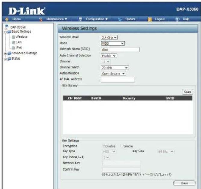
Site Survey: Click on the Scan button to search for available wireless networks, then click on the available network that you want to connect with.
Authentication: Use the drop-down menu to choose Open System or WPA-Personal.
- Select Open System to communicate the key across the network.
- Select WPA-Personal to secure your network using a password and dynamic key changes. No RADIUS server is required.
Note: It is highly recommended that you use WPA-Personal to encrypt your network.
©
Wi-Fi Protected Access (WPA / WPA2 / WPA3)
WPA was created by the Wi-Fi Alliance to address the limitations and weaknesses found in WEP. This protocol is mainly based on the 802.11i standard. There are also two variations found in WPA called WPA-Personal (PSK) and WPA-Enterprise (EAP).
WPA-EAP requires the user to install a RADIUS Server on the network for authentication. WPA-Personal does not require the user to install a RADIUS Server on the network.
Comparing WPA-PSK with WPA-EAP, WPA-PSK is seen as a weaker authentication but comparing WPA-PSK to WEP, WPA-PSK is far more secure than WEP. WPA-EAP is the highest level of wireless security a user can use for wireless today.
WPA2/WPA3 are upgrades of WPA. WPA2/WPA3 yet again solves some possible security issues found in WPA. WPA2/WPA3 have two variations called WPA2/WPA3-Personal (PSK) and WPA2/WPA3-Enterprise (EAP) which are the same as found with WPA.
WPA Mode: When WPA-Personal is selected for Authentication type, you must also select a WPA mode from the drop-down menu: AUTO (WPA or WPA2), WPA2 or WPA3, WPA2 Only or WPA3 Only.
Cipher Type: When you select WPA-Personal, you must also select AUTO, AES, or TKIP from the drop-down menu.
Group Key Update: Select the interval during which the group key will be valid. The default value of 3600 is recommended.
Pass Phrase: When you select WPA-Personal, enter a Pass Phrase in the corresponding field.

Section 3 - Configuration
| WPA Mode: | When WPA-Enterprise is selected, you must also select a WPA mode from the drop-down menu: AUTO (WPA or WPA2) or WPA2 Only or WPA3 only. |
| Cipher Type: | When WPA-Enterprise is selected, you must also select a cipher type from the drop-down menu: Auto, AES, or TKIP. |
| Group Key Update Interval: | Select the interval during which the group key will be valid. 3600 is the recommended value as a lower interval may reduce data transfer rates. |
| RADIUS Server: | Enter the IP address of the RADIUS server to be used in authenticate. |
| RADIUS Port: | Enter the RADIUS port. |
| RADIUS Secret: | Enter the shared secret to be used between the radius server and the DAP to authenticate. |
| Accounting Mode: | Click the drop-down menu to enable or disable the accounting mode. |
| Accounting Server: | Enter the IP address of the accounting server. |
| Accounting Port: | Enter the accounting port. |
| Accounting Secret: | Enter the accounting secret. |
| Save: | Save the updated configuration. Click Configuration > Save and Activate to make changes permanent. |

LAN
LAN is short for Local Area Network. This is considered your internal network. These are the IP settings of the LAN interface for the DAP-E9560. These settings may be referred to as private settings. You may change the LAN IP address if needed. The LAN IP address is private to your internal network and cannot be seen on the Internet.
Get IP From: Dynamic IP (DHCP) is chosen here. Choose this option if you have a DHCP server in your network, or if you wish to assign a static IP address to the DAP-E9560. When Dynamic IP (DHCP) is selected, the other fields here will be grayed out. Please allow about 2 minutes for the DHCP client to be functional once this selection is made.
IP Address: Assign a static IP address that is within the IP address range of your network.
Subnet Mask: Enter the subnet mask. All devices in the network must share the same subnet mask.
Default Gateway: Enter the IP address of the gateway/router in your network.
DNS: Enter a DNS server IP address. This is usually the local IP address of your gateway/router.

IPv6
Enable IPv6: Check to enable IPv6
Get IP From: Dynamic IP is chosen here. Choose this option the DAP-E9560 can get IPv6 address automatically or use Static to set IPv6 address manually. When Auto is selected, the other fields here will be grayed out.
IPv6 Address: Enter the LAN IPv6 address used here.
Prefix: Enter the LAN subnet prefix length value used here.
Default Gateway: Enter the LAN default gateway IPv6 address used here.

Advanced Settings
In the Advanced Settings Section the user can configure advanced settings concerning Performance, Wireless Resource, Multi-SSID, VLAN, Intrusion, Schedule, Internal RADIUS Server, ARP Spoofing Prevention, Bandwidth Optimization, Captive Portal, DHCP Server, Filters and Traffic Control. The following pages will explain settings found in the Advanced Settings section in more detail.

Performance
On the Performance Settings page the users can configure more advanced settings concerning the wireless signal and hosting.
Wireless Band: Select 2.4GHz or 5GHz or 6GHz.
Wireless: Use the drop-down menu to turn the wireless function On or Off.
Wireless Mode: The supported client mode combinations include: Mixed 802.11b/g/n, Mixed 802.11b/g, 802.11n Only, Mixed 802.11ax, and Mixed 802.11be modes in the 2.4 GHz band; Mixed 802.11a/n, 802.11a Only, 802.11n Only, Mixed 802.11ac, Mixed 802.11ax, and Mixed 802.11be modes in the 5 GHz band; and 802.11ax Only and Mixed 802.11be modes in the 6 GHz band. Please note that when backwards compatibility is enabled for legacy (802.11a/g/b) clients, degradation of 802.11n wireless performance is expected.
Data Rate*: Indicate the base transfer rate of wireless adapters on the wireless LAN. The AP will adjust the base transfer rate depending on the base rate of the connected device. If there are obstacles or interference, the AP will step down the rate.
Beacon Interval (40-500): Beacons are packets sent by an access point to synchronize a wireless network. Specify a value in milliseconds. The default (100) is recommended. Setting a higher beacon interval can help to save the power of wireless clients, while setting a lower one can help a wireless client connect to an access point faster.

DTM Interval (1-15): Select a Delivery Traffic Indication Message setting between 1 and 15. 1 is the default setting. DTIM is a countdown informing clients of the next window for listening to broadcast and multicast messages.
Section 3 - Configuration
| Transmit Power: | This setting determines the power level of the wireless transmission. Transmitting power can be adjusted to eliminate overlapping of wireless area coverage between two access points where interference is a major concern. For example, if wireless coverage is intended for half of the area, then select 50% as the option. Use the drop-down menu to select 100%, 50%, 25%, or 12.5%. |
| WMM (Wi-Fi Multimedia): | WMM stands for Wi-Fi Multimedia. Enabling this feature will improve the user experience for audio and video applications over a Wi-Fi network. This setting only available when legacy client ([802.11a only mode][Mixed b/g mode]) is selected. |
| Ack Time Out: | To effectively optimize throughput over long distance links enter a value for Acknowledgement Time Out between 64 and 200 microseconds for 6GHz, 5GHz and 2.4 GHz in the field provided. |
| Short GI: | Select Enable or Disable. Enabling a short guard interval can increase throughput. However, be aware that it can also increase the error rate in some installations due to increased sensitivity to radio-frequency installations. This setting not available when legacy client ([802.11a only mode][Mixed b/g mode]) is selected. |
| IGMP Snooping: | Select Enable or Disable. Internet Group Management Protocol allows the AP to recognize IGMP queries and reports sent between routers and an IGMP host (wireless STA). When IGMP snooping is enabled, the AP will forward multicast packets to an IGMP host based on IGMP messages passing through the AP. This setting not available when WDS mode is enabled. |
| Multicast Rate: | Select the multicast rate to adjust multicast packet data rates. This setting only available when [Mixed b/g/n mode][Mixed b/g mode][Mixed a/n mode][802.11a only mode] is selected |
| Multicast BandwidthControl: | Adjust the multicast packet data rate here. The Multicast Bandwidth Control is supported in AP mode, (2.4 GHZ and 5 GHZ) and WDS with AP mode, including Multi-SSIDs. This setting not available when WDS mode is enabled. |
| Maximum Multicast Bandwidth: | Set the multicast packets' maximum bandwidth pass through rate from the Ethernet interface to the Access Point. |
| HT20/40 Coexistence: | Enable this option to reduce interference from other wireless networks in your area. If the channel width is operating at 40 MHz and there is another wireless network's channel overlapping and causing interference, the Access Point will automatically change to 20 MHz. |
| Transfer DHCP Offer to Unicast: | Enable to transfer the DHCP Offer to Unicast from LAN to WLAN. It is suggested to enable this function if stations number is larger than 30. |
Wireless Resource
The Wireless Resource Control window is used to configure the wireless connection settings so that the device can detect the better wireless connection in your environment.
Airtime Fairness: Click the drop-down menu to enable or disable the airtime fairness function.
Band Steering: Click the drop-down menu to enable the band steering function. When the wireless clients support multiple bands such as 2.4GHz, 5GHz, and 6GHz, and the 2.4GHz or 5GHz signal is not strong enough, the device will prioritize the 6GHz band if available, followed by 5GHz, to ensure better performance.
Wireless Band: Click the drop-down menu to select the wireless band, 2.4GHz or 5GHz or 6GHz.
Connection Limit: Click the drop-down menu to enable or disable the connection limit function. The option is for load balancing. This determines whether to limit the number of users accessing this device. The exact number is entered in the User Limit field below. This feature allows the user to share the wireless network traffic and the client using multiple APs. If this function is enabled and when the number of users exceeds this value, or the network utilization of this AP exceeds the percentage that has been specified, the DAP-E9560 will not allow clients to associate with the AP.
User Limit (0 - 64): This function is only available when Connection Limit is enabled. Set the maximum amount of users that are allowed access (0 - 64 users) to the device using the specified wireless band.

11n/ac/ax/be Preferred: This function is only available when Connection Limit is enabled. Use the drop-down menu to enable the 11n/ac/ax/be Preferred function. The wireless clients with 802.11n/ac/ax/be protocol will have higher priority to connect to the device.
Network Utilization: Click the drop-down menu to set the maximum utilization of this access point for service. The DAP-E9560 will not allow any new clients to associate with the AP if the utilization exceeds the value the user specifies. When this network utilization threshold is reached, the device will pause for one minute to allow network congestion to dissipate.
Aging out: Use the drop-down menu to select the criteria for disconnecting the wireless clients.
RSSI Threshold: When Aging out is RSSI, click the drop-down menu to select the percentage of RSSI. When the RSSI of wireless clients is lower than the specified percentage, the device disconnects the wireless clients. The function is only available when Aging out is RSSI.
Data Rate Threshold: When Aging out is Data Rate, click the drop-down menu to select the threshold of data rate. When the data rate of wireless clients is lower than the specified number, the device disconnects the wireless clients. The function is only available when Aging out is Data Rate.
ACL RSSI: Click the drop-down menu to enable the ACL RSSI function. When enabled, the device denies the connection request from the wireless clients with the RSSI lower than the specified threshold below.
ACL RSSI Threshold: Click the drop-down menu to set the ACL RSSI Threshold.
Save: Click to save the updated configuration. To make the updates permanent, click Configuration > Save and Activate.
Multi-SSID
The device supports up to eight multiple Service Set Identifiers per radio. You can set the Primary SSID in the Basic > Wireless section. The SSID's factory default setting is dlink. The SSID can be easily changed to connect to an existing wireless network or to establish a new wireless network.
Enable Multi-SSID: Check to enable support for multiple SSIDs.
Enable Priority: Check to enable the Priority function.
Band: Select 2.4GHz or 5GHz or 6GHz.
Index: You can select up to seven multi-SSIDs. With the Primary SSID, you have a total of eight multi-SSIDs per radio.
MLO ID: Defines the logical group identity for devices participating in a multi-link operation. Default is disable.
SSID: Service Set Identifier (SSID) is the name designated for a specific wireless local area network (WLAN). The SSID's factory default setting is dlink. The SSID can be easily changed to connect to an existing wireless network or to establish a new wireless network.

SSID Visibility: Enable or Disable SSID visibility. Enabling this feature broadcasts the SSID across the network, thus making it visible to all network users.
Security: The Multi-SSID security can be Open System, WPA-Personal, or WPA-Enterprise. For a detailed description of the Open System parameters please go to pages 17. For a detailed description of the WPA-Personal parameters please go to page 18. For a detailed description of the WPA-Enterprise parameters please go to page 19.
Note: It is highly recommended that you encrypt your network for all SSIDs in Multi-SSID configuration.
Note: It is highly recommended that you encrypt your network for all SSIDs in Multi-SSID configuration.
Priority: Select the priority level of the SSID selected.
WMM (Wi-Fi) WMM stands for Wi-Fi Multimedia. Enabling this feature will improve the user experience for audio and video applications over a Wi-Fi Multimedia): network.
Encryption: When you select Open System, toggle between Enable and Disable. If Enable is selected, the Key Type, Key Size, Key Index (1\~4), Key, and Confirm Keys must also be configured.
Key Type: Select HEX or ASCII.
Key Size: Select 64-bit or 128-bit.
Key Index (1-4): Select from the 1st to 4th key to be set as the active key.
Key: Input up to four keys for encryption. You will select one of these keys in the Key Index drop-down menu.
WPA Mode: When you select either WPA-Personal or WPA-Enterprise, you must also choose a WPA mode from the drop-down menu.
Cipher Type: Select Auto, AES, or TKIP from the drop-down menu.
Group Key Update Interval: Select the interval during which the group key will be valid. The default value of 3600 seconds is recommended.
Pass Phrase: When you select WPA-Personal, please enter a Pass Phrase in the corresponding field.
Confirm Pass Phrase: When you select WPA-Personal, please re-enter the Pass Phrase entered in the previous item in the corresponding field.
RADIUS Server: When you select WPA-Enterprise, enter the IP address of the RADIUS server. In addition, you must configure RADIUS Port and RADIUS Secret.
RADIUS Port: Enter the RADIUS port.
RADIUS Secret: Enter the RADIUS secret.
Accounting Mode: Click the drop-down menu to enable or disable the accounting mode.
Accounting Server: Enter the IP address of the accounting server.
VLAN
VLAN List
The DAP-E9560 supports VLANs. VLANs can be created with a Name and VID. Mgmt (TCP stack), LAN, Primary/Multiple SSID, and WDS connection can be assigned to VLANs as they are physical ports. Any packet which enters the DAP-E9560 without a VLAN tag will have a VLAN tag inserted with a PVID. The VLAN List tab displays the current VLANs.
VLAN Status: Use the radio button to toggle to Enable. Next, go to the Add/Edit VLAN tab to add or modify an item on the VLAN List tab.
VLAN Mode: The current VLAN mode is displayed.
Save: Click to save the updated configuration. To make the updates permanent, click Configuration > Save and Activate.
VID: Displays the VID of the VLAN.
VLAN Name: Displays the name of the VLAN.
Untag VLAN Ports Displays the untagged ports.
Tag VLAN Ports: Displays the tagged ports.
Edit: Clink the icon to edit the current VLAN.
Delete: Click the icon to delete the current VLAN.

Port List
The Port List tab displays the current ports. If you want to configure the guest and internal networks on a Virtual LAN (VLAN), the switch and DHCP server you are using must also support VLANs. As a prerequisite step, configure a port on the switch for handling VLAN tagged packets as described in the IEEE 802.1Q standard.
VLAN Status: Use the radio button to toggle to Enable. Next, go to the Add/Edit VLAN tab to add or modify an item on the VLAN List tab.
VLAN Mode: Displays the current VLAN mode.
Save: Click to save the updated configuration. To make the updates permanent, click Configuration > Save and Activate.
Port Name: The name of the port is displayed in this column.
Tag VID: The Tagged VID is displayed in this column.
Untag VID: The Untagged VID is displayed in this column.
PVID: The Port VLAN Identifier is displayed in this column.

Add/Edit VLAN
The Add/Edit VLAN tab is used to configure VLANs. Once you have made the desired changes, click the Save button to let your changes take effect.
VLAN Status: Use the radio button to toggle to Enable.
VLAN Mode: Displays the current VLAN mode.
VLAN ID: Provide a number between 1 and 4094 for the Internal VLAN.
VLAN Name: Enter the VLAN to add or modify.
Save: Click to save the updated configuration. To make the updates permanent, click Configuration > Save and Activate.

PVID Settings
The PVID Setting tab is used to enable/disable the Port VLAN Identifier Auto Assign Status as well as to configure various types of PVID settings. Click the Save button to let your changes take effect.
VLAN Status: Use the radio button to toggle between Enable and Disable.
VLAN Mode: Displays the current VLAN mode.
PVID Auto Assign Status: Use the radio button to toggle PVID auto assign status to Enable.

Intrusion
The Wireless Intrusion Protection window is used to set APs as All, Valid, Neighborhood, Rogue, and New. Click the Save button to let your changes take effect.
Wireless Band: Select 2.4GHz or 5GHz or 6GHz.
AP List: Click the drop-down menu to select All, Valid, Neighbor, Rogue, and New.
The following is a definition of the listed AP categories:
- Valid: An AP which is authenticated to the network with encryption is classified as valid.
- Neighbor: A detected AP with a weak signal strength is classified as a suspect neighbor.
- Rogue: An AP that has been installed on the secure network without explicit authorization.
• New: An alternative category.
From the AP List select a detected AP and click Set as Valid, Set as Neighborhood, Set as Rogue, or Set as New to manually define the category type for the AP. Alternatively, click the radio button to mark all new access points as valid or rogue.

Save: Click to save the updated configuration.
To make the updates permanent, click
Configuration > Save and Activate.
Schedule
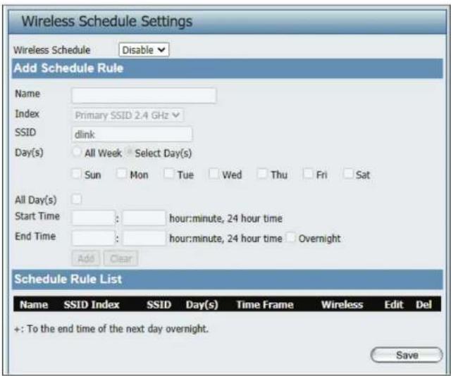
The Wireless Schedule Settings window is used to add and modify scheduling rules on the device. Click the Save button to let your changes take effect.
Wireless Schedule: Use the drop-down menu to enable the device's scheduling feature.
Name: Enter a name for the new scheduling rule in the field provided.
Index: Use the drop-down menu to select the desired SSID.
SSID: This read-only field indicates the current SSID in use. To create a new SSID, go to the Wireless Settings window (Basic Settings > Wireless).
Day(s): Toggle the radio button between All Week and Select Day(s). If the second option is selected, check the specific days you want the rule to be effective on.
All Day(s): Check this box to have your settings apply 24 hours a day.
Start Time: Enter the beginning hour and minute, using a 24-hour clock.
End Time: Enter the ending hour and minute, using a 24-hour clock.
Internal RADIUS Server
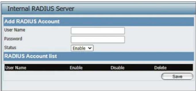
The DAP-E9560 features a built-in RADIUS server. Once you have finished adding a RADIUS account, click the Save button to let your changes take effect. The newly-created account will appear in this RADIUS Account List. The radio buttons allow the user to enable or disable the RADIUS account. Click the icon in the delete column to remove the RADIUS account. We suggest you limit the number of accounts below 30.
User Name: Enter a name to authenticate user access to the internal RADIUS server.
Password: Enter a password to authenticate user access to the internal RADIUS server. The length of your password should be 8\~64.
Status: Toggle the drop-down menu between Enable and Disable.
RADIUS Account List: Displays the list of users.
ARP Spoofing Prevention
The ARP Spoofing Prevention feature allows users to add IP/MAC address mapping to prevent ARP spoofing attacks.
ARP Spoofing Prevention: This drop-down allows you to enable the ARP spoofing prevention function.
Add: Click to create a defined rule.
Clear: Click to clear a defined rule.
Gateway IP Address: Enter a gateway IP address.
Gateway MAC Address: Enter a gateway MAC address.
Delete All: Click to delete all gateway entries.
Edit: Click to edit the selected gateway entry.
Delete: Click to delete the gateway entry.
Save: Click to save the updated configuration. To make the updates permanent, click Configuration > Save and Activate.

Bandwidth Optimization
The Bandwidth Optimization window allows the user to manage the bandwidth of the device and arrange the bandwidth for various wireless clients. When the Bandwidth Optimization rule is finished, click the Add button. To discard the Add Bandwidth Optimization Rule settings, click the Clear button. Click the Save button to let your changes take effect.
| Enable Bandwidth Optimization: | Use the drop-down menu to Enable the Bandwidth Optimization function. |
| Downlink Bandwidth: | Enter the downlink bandwidth of the device in Mbits per second. |
| Uplink Bandwidth: | Enter the uplink bandwidth of the device in Mbits per second. |
| Allocate average BW for each station: | AP will distribute average bandwidth for each client. |
| Allocate maximum BW for each station: | Specify the maximum bandwidth for each connected client. Reserve certain bandwidth for future clients. |
| Allocate different BW for a/b/g/n stations: | The weight of 11b/g/n and 11a/n client are 10%/20%/70% and 20%/80%. AP will distribute different bandwidth for 11a/b/g/n clients. |
| Allocate specific BW for SSID: | All clients share the total bandwidth. |
| Rule Type: | Use the drop-down menu to select the type that is applied to the rule. Available options are: Allocate average BW for each station, Allocate maximum BW for each station, Allocate different BW for 1a/b/g/n stations, and Allocte specific BW for SSID. |

Section 3 - Configuration
Band: Use the drop-down menu to toggle the wireless band between 2.4GHz, 5GHz or 6GHz.
SSID Index: Use the drop-down menu to select the SSID for the specified wireless band.
Downlink Speed: Enter the limitation of the downloading speed in either Kbits/sec or Mbits/sec for the rule.
Uplink Speed: Enter the limitation of the uploading speed in either Kbits/sec or Mbits/sec for the rule.
Add: Click to create a defined rule.
Clear: Click to remove the settings from the menu interface.
Edit: Click to edit the selected gateway entry.
Delete: Click to delete the gateway entry.
Save: Click to save the updated configuration. To make the updates permanent, click Configuration > Save and Activate.
Captive Portal
Authentication Settings-Web Redirection Only
The Captive Portal is a built-in web authentication server. When a station connects to an AP, the web browser will be redirected to a web authentication page. In this window, users can view and configure the Captive Portal settings. After selecting Web Redirection Only as the Authentication Type, we can configure the redirection website URL that will be applied to each wireless client in this network.
Idle Timeout(1-1440): Enter the session timeout value here. This value can be from 1 to 1440 minutes. By default, this value is 60 minutes.
Band: Select 2.4GHz, 5GHz or 6GHz.
SSID Index: Select the SSID for this Authentication.
Authentication Type: Select the captive portal encryption type here. Options to choose from are Web Redirection, Username/Password, Passcode, Remote RADIUS, LDAP and POP3. In this section we'll discuss the Web Redirection option.
Web Redirection State: The default setting is Enable when you select Web Redirection Only.
URL Path: Select whether to use either HTTP or HTTPS here. After selecting either http:// or https://, enter the URL of the website that will be used in the space provided.
IPIF Status: Select to Enable or Disable the Captive Portal with its IP interface feature here.
VLAN Group: Enter the VLAN Group ID here.

Section 3 - Configuration
| Get IP From: | Static IP (Manual) is chosen here. Choose this option if you do not have a DHCP server in your network, or if you wish to assign a static IP address to the DAP-E9560. When Dynamic IP (DHCP) is selected, the other fields here will be grayed out. Please allow about 2 minutes for the DHCP client to be functional once this selection is made. |
| IP Address: | Assign a static IP address that is within the IP address range of your network. |
| Subnet Mask: | Enter the subnet mask. All devices in the network must share the same subnet mask. |
| Gateway: | Enter the IP address of the gateway/router in your network. |
| DNS: | Enter a DNS server IP address. This is usually the local IP address of your gateway/router. |
| Edit: | Click to edit the selected entry. |
| Delete: | Click to delete the entry. |
| Save: | Click to save the updated configuration. To make the updates permanent, click Configuration > Save and Activate. |
Authentication Settings-Username/Password
The Captive Portal is a built-in web authentication server. When a station connects to an AP, the web browser will be redirected to a web authentication page. In this window, users can view and configure the Captive Portal settings. After selecting Username/Password as the Authentication Type, we can configure the Username/Password authentication that will be applied to each wireless client in this network.
Session timeout(1-1440): Enter the session timeout value here. This value can be from 1 to 1440 minutes. By default, this value is 60 minutes.
Band: Select 2.4GHz or 5GHz or 6GHz.
SSID Index: Select the SSID for this Authentication.
Authentication Type: Select the captive portal encryption type here. Options to choose from are Web Redirection, Username/Password, Passcode, Remote RADIUS, LDAP and POP3. In this section we'll discuss the Username/Password option.
Web Redirection State: Disable is default setting. Select Enable to enable the website redirection feature.
URL Path: Select whether to use HTTP or HTTPS. After selecting either http://or https://, enter the URL of the website that will be used in the space provided.
IPIF Status: Select to Enable or Disable the Captive Portal with its IP interface feature here.
VLAN Group: Enter the VLAN Group ID here.

Section 3 - Configuration
| Get IP From: | Static IP (Manual) is chosen here. Choose this option if you do not have a DHCP server in your network, or if you wish to assign a static IP address to the DAP-E9560. When Dynamic IP (DHCP) is selected, the other fields here will be grayed out. Please allow about 2 minutes for the DHCP client to be functional once this selection is made. |
| IP Address: | Assign a static IP address that is within the IP address range of your network. |
| Subnet Mask: | Enter the subnet mask. All devices in the network must share the same subnet mask. |
| Gateway: | Enter the IP address of the gateway/router in your network. |
| DNS: | Enter a DNS server IP address. This is usually the local IP address of your gateway/router. |
| Username: | Enter the username for the new account here. |
| Password: | Enter the password for the new account here. |
| Add: | Click to create a defined rule. |
| Clear: | Click to remove the settings from the menu interface. |
| Edit: | Click to edit the selected gateway entry. |
| Delete: | Click to delete the gateway entry. |
| Save: | Click to save the updated configuration. To make the updates permanent, click Configuration > Save and Activate. |
Authentication Settings- Passcode
The Captive Portal is a built-in web authentication server. When a station connects to an AP, the web browser will be redirected to a web authentication page. In this window, users can view and configure the Captive Portal settings. After selecting Passcode as the Authentication Type, you can configure the Passcode authentication that will be applied to each wireless client in this network.
Session timeout(1-1440): Enter the session timeout value here. This value can be from 1 to 1440 minutes. By default, this value is 60 minutes.
Band: Select 2.4GHz or 5GHz or 6GHz.
SSID Index: Select the SSID for this Authentication.
Authentication Type: Select the captive portal encryption type here. Options to choose from are Web Redirection, Username/Password, Passcode, Remote RADIUS, LDAP and POP3. In this section we'll discuss the Passcode option.
Web Redirection State: The default setting is Disable. Select Enable to enable the website redirection feature.
URL Path: Select whether to use HTTP or HTTPS here. After selecting either http:// or https://, enter the URL of the website that will be used in the space provided.
IPIF Status: Select to Enable or Disable the Captive Portal with its IP interface feature here.
VLAN Group: Enter the VLAN Group ID here.

Section 3 - Configuration
| Get IP From: | Static IP (Manual) is chosen here. Choose this option if you do not have a DHCP server in your network, or if you wish to assign a static IP address to the DAP-E9560. When Dynamic IP (DHCP) is selected, the other fields here will be grayed out. Please allow about 2 minutes for the DHCP client to be functional once this selection is made. |
| IP Address: | Assign a static IP address that is within the IP address range of your network. |
| Subnet Mask: | Enter the subnet mask. All devices in the network must share the same subnet mask. |
| Gateway: | Enter the IP address of the gateway/router in your network. |
| DNS: | Enter a DNS server IP address. This is usually the local IP address of your gateway/router. |
| Passcode Quantity: | Enter the number of ticket that will be used here. |
| Duration: | Enter the duration value, in hours, for this passcode. |
| Last Active Day: | Select the last active date for this passcode here. Year, Month and Day selections can be made. |
| User Limit: | Enter the maximum amount of users that can use this passcode at the same time |
Section 3 - Configuration
Add: Click to create a defined rule.
Clear: Click to remove the settings from the menu interface.
Delete All: Click to delete all passcode setting entries
Edit: Click to edit the selected entry.
Delete: Click to delete the entry.
Save: Click to save the updated configuration. To make the updates permanent, click Configuration > Save and Activate.
Authentication Settings- Remote RADIUS
The Captive Portal is a built-in web authentication server. When a station connects to an AP, the web browser will be redirected to a web authentication page. In this window, users can view and configure the Captive Portal settings. After selecting Remote RADIUS as the Authentication Type, you can configure the Remote RADIUS authentication that will be applied to each wireless client in this network.
Session timeout(1-1440): Enter the session timeout value here. This value can be from 1 to 1440 minutes. By default, this value is 60 minutes.
Band: Select 2.4GHz or 5GHz or 6GHz.
SSID Index: Select the SSID for this Authentication.
Authentication Type: Select the captive portal encryption type here. Options to choose from are Web Redirection, Username/Password, Passcode, Remote RADIUS, LDAP and POP3. In this section we'll discuss the Remote RADIUS option.
Web Redirection State: The default setting is Disable. Select Enable to enable the website redirection feature.
URL Path: Select whether to use either HTTP or HTTPS here. After selecting either http:// or https://, enter the URL of the website that will be used in the space provided.
IPIF Status: Select to Enable or Disable the Captive Portal with its IP interface feature here.
VLAN Group: Enter the VLAN Group ID here.

Section 3 - Configuration
| Get IP From: | Static IP (Manual) is chosen here. Choose this option if you do not have a DHCP server in your network, or if you wish to assign a static IP address to the DAP-E9560. When Dynamic IP (DHCP) is selected, the other fields here will be grayed out. Please allow about 2 minutes for the DHCP client to be functional once this selection is made. |
| IP Address: | Assign a static IP address that is within the IP address range of your network. |
| Subnet Mask: | Enter the subnet mask. All devices in the network must share the same subnet mask. |
| Gateway: | Enter the IP address of the gateway/router in your network. |
| DNS: | Enter a DNS server IP address. This is usually the local IP address of your gateway/router. |
| Radius Server: | Enter the RADIUS server's IP address here |
| Radius Port: | Enter the RADIUS server's port number here |
| Radius Port: | Enter the RADIUS server's shared secret here |
| Remote Radius Type: | Select the remote RADIUS server type here. The default setting is SPAP. |
| Edit: | Click to edit the selected entry. |
| Delete: | Click to delete the entry. |
| Save: | Click to save the updated configuration. To make the updates permanent, click Configuration > Save and Activate. |
Authentication Settings- LDAP
The Captive Portal is a built-in web authentication server. When a station connects to an AP, the web browser will be redirected to a web authentication page. In this window, users can view and configure the Captive Portal settings. After selecting LDAP as the Authentication Type, you can configure the LDAP authentication that will be applied to each wireless client in this network.
Session Enter the session timeout value here. This value can timeout(1-1440): be from 1 to 1440 minutes. By default, this value is 60 minutes.
Band: Select 2.4GHz or 5GHz or 6GHz.
SSID Index: Select the SSID for this Authentication.
Authentication Type: Select the captive portal encryption type here. Options to choose from are Web Redirection, Username/Password, Passcode, Remote RADIUS, LDAP and POP3. In this section we'll discuss the LDAP option.
Web Redirection State: The default setting is Disable. Select Enable to enable the website redirection feature.
URL Path: Select whether to use either HTTP or HTTPS here. After selecting either http://or https://, enter the URL of the website that will be used in the space provided.
IPIF Status: Select to Enable or Disable the Captive Portal with its IP interface feature here.
VLAN Group: Enter the VLAN Group ID here.
Get IP From: Static IP (Manual) is chosen here. Choose this option if you do not have a DHCP server in your network, or if you wish to assign a static IP address to the DAP-E9560. When Dynamic IP (DHCP) is selected, the other fields here will be grayed out. Please allow about 2 minutes for the DHCP client to be functional once this selection is made.

Section 3 - Configuration
| IP Address: | Assign a static IP address that is within the IP address range of your network. |
| Subnet Mask: | Enter the subnet mask. All devices in the network must share the same subnet mask. |
| Gateway: | Enter the IP address of the gateway/router in your network. |
| DNS: | Enter a DNS server IP address. This is usually the local IP address of your gateway/router. |
| Server: | Enter the LDAP server's IP address or domain name here. |
| Port: | Enter the LDAP server's port number here. |
| Authenticate Mode: | Select the authentication mode here. Options to choose from are Simple and TLS. |
| Username: | Enter the LDAP server account's username here. |
| Password: | Enter the LDAP server account's password here. |
| Base DN: | Enter the administrator's domain name here |
| Account Attribute: | Enter the LDAP account attribute string here. This string will be used to search for clients. |
| Identity: | Enter the identity's full path string here. Alternatively, select the Auto Copy checkbox to automatically add the generic full path of the web page in the identity field. |
| Edit: | Click to edit the selected entry. |
| Delete: | Click to delete the entry. |
| Save: | Click to save the updated configuration. To make the updates permanent, click Configuration > Save and Activate. |
Authentication Settings- POP3
The Captive Portal is a built-in web authentication server. When a station connects to an AP, the web browser will be redirected to a web authentication page. In this window, users can view and configure the Captive Portal settings. After selecting POP3 as the Authentication Type, you can configure the POP3 authentication that will be applied to each wireless client in this network.
Session timeout(1-1440): Enter the session timeout value here. This value can be from 1 to 1440 minutes. By default, this value is 60 minutes.
Band: Select 2.4GHz or 5GHz or 6GHz.
SSID Index: Select the SSID for this Authentication.
Authentication Type: Select the captive portal encryption type here. Options to choose from are Web Redirection, Username/Password, Passcode, Remote RADIUS, LDAP and POP3. In this section we'll discuss the POP3 option.
Web Redirection State: The default setting is Disable. Select Enable to enable the website redirection feature.
URL Path: Select whether to use either HTTP or HTTPS here. After selecting either http:// or https://, enter the URL of the website that will be used in the space provided.
IPIF Status: Select to Enable or Disable the Captive Portal with its IP interface feature here.
VLAN Group: Enter the VLAN Group ID here.

Section 3 - Configuration
Get IP From: Static IP (Manual) is chosen here. Choose this option if you do not have a DHCP server in your network, or if you wish to assign a static IP address to the DAP-E9560. When Dynamic IP (DHCP) is selected, the other fields here will be grayed out. Please allow about 2 minutes for the DHCP client to be functional once this selection is made.
IP Address: Assign a static IP address that is within the IP address range of your network.
Subnet Mask: Enter the subnet mask. All devices in the network must share the same subnet mask.
Gateway: Enter the IP address of the gateway/router in your network.
DNS: Enter a DNS server IP address. This is usually the local IP address of your gateway/router.
Server: Enter the POP3 server's IP address or domain name here.
Port: Port: Enter the POP server's port number here.
Connection Type: Select the connection type here. Options to choose from are None and SSL/TLS.
Edit: Click to edit the selected entry.
Delete: Click to delete the entry.
Save: Click to save the updated configuration. To make the updates permanent, click Configuration > Save and Activate.
Login Page Upload
In this window, users can upload a custom login web page that will be used by the captive portal feature. Click the Browse button to navigate to the login style located on the managing computer and then click the Upload button to initiate the upload.
Upload Login Style In this field the path to the login style file that From Local Hard Drive: will be uploaded is be displayed. Alternatively, the path can be manually entered here.
Login Page Style List: Select the wireless band and login style that will be used in each SSID here. Click the download button to download the template file for the login page and click the delete button to delete the template file.
Save: Click to save the updated configuration. To make the updates permanent, click Configuration > Save and Activate.

MAC Bypass
The DAP-E9560 features a wireless MAC Bypass. Once finished editing these settings, click the Save button to let the changes take effect.
Wireless Band: Select the wireless band for MAC Bypass.
SSID Index: Select the SSID for MAC Bypass.
MAC Address: Enter each MAC address that you wish to include in your bypass list, and click Add.
MAC Address List: When a MAC address is entered, it appears in this list. Highlight a MAC address and click the Delete icon to remove it from this list.
Upload File: To upload a MAC bypass list file, click Browse and navigate to the MAC bypass list file saved on the computer, and then click Upload.

Load MAC File to Local To download MAC bypass list file, click Download Hard Driver: and save the MAC bypass list.
Save: Click to save the updated configuration. To make the updates permanent, click Configuration > Save and Activate.
DHCP Server
Dynamic Pool Settings
The DHCP address pool defines the range of the IP address that can be assigned to stations in the network. A Dynamic Pool allows wireless stations to receive an available IP with lease time control. If needed or required in the network, the DAP-E9560 is capable of acting as a DHCP server.
Function Enable/Disable: Dynamic Host Configuration Protocol (DHCP) assigns dynamic IP addresses to devices on the network. This protocol simplifies network management and allows new wireless devices to receive IP addresses automatically without the need to manually assign new IP addresses. Select Enable to allow the DAP-E9560 to function as a DHCP server.
IP Assigned From: Input the first IP address available for assignment on your network.
IP Pool Range(1-254): Enter the number of IP addresses available for assignment. IP addresses are increments of the IP address specified in the "IP Assigned From" field.

Subnet Mask: All devices in the network must have the same subnet mask to communicate. Enter the subnet mask for the network here.
Gateway: Enter the IP address of the gateway on the network.
WINS: Specify the Windows Internet Naming Service (WINS) server address for the wireless network. WINS is a system that determines the IP address of a network computer that has a dynamically assigned IP address.
DNS: Enter the IP address of the Domain Name System (DNS) server. The DNS server translates domain names such as www.dlink.com into IP addresses.
Domain Name: Enter the domain name of the network, if applicable. (An example of a domain name is: www.dlink.com.)
Lease Time: The lease time is the period of time before the DHCP server will assign new IP addresses.
Save: Click to save the updated configuration. To make the updates permanent, click Configuration > Save and Activate.
Static Pool Setting
The DHCP address pool defines the range of IP addresses that can be assigned to stations on the network. A static pool allows specific wireless stations to receive a fixed IP without time control.
Function Enable/Disable: Dynamic Host Configuration Protocol (DHCP) assigns IP addresses to wireless devices on the network. This protocol simplifies network management and allows new wireless devices to receive IP addresses automatically without the need to manually assign IP addresses. Select Enable to allow the DAP-E9560 to function as a DHCP server.
Assigned IP: Use the Static Pool Settings to assign the same IP address to a device every time you start up. The IP addresses assigned in the Static Pool list must NOT be in the same IP range as the Dynamic Pool. After you have assigned a static IP address to a device via its MAC address, click Apply; the device will appear in the Assigned Static Pool at the bottom of the screen. You can edit or delete the device in this list.
Assigned MAC Address: Enter the MAC address of the device requesting association here.
Subnet Mask: Define the subnet mask of the IP address specified in the "IP Assigned From" field.

Gateway: Specify the Gateway address for the wireless network.
WINS: Specify the Windows Internet Naming Service (WINS) server address for the wireless network. WINS is a system that determines the IP address of a network computer with a dynamically assigned IP address, if applicable.
DNS: Enter the DNS server address for your wireless network.
Domain Name: Specify the domain name for the network.
Save: Click to save the updated configuration. To make the updates permanent, click Configuration > Save and Activate.
Current IP Mapping List
This window displays information about the current assigned DHCP dynamic and static IP address pools. This information is available when you enable the DHCP server on the AP and assign dynamic and static IP address pools.
Current DHCP Dynamic These are IP address pools the DHCP server has Profile: assigned using the dynamic pool setting.
Binding MAC Address: The MAC address of a device on the network that is assigned an IP address from the DHCP dynamic pool.
Assigned IP Address: The current corresponding DHCP-assigned IP address of the device.
Lease Time: The length of time that the dynamic IP address will be valid.
Current DHCP Static Pools: These are the IP address pools of the DHCP server assigned through the static pool settings.
Binding MAC Address: The MAC address of a device on the network that is within the DHCP static IP address pool.
Assigned IP Address: The current corresponding DHCP-assigned static IP address of the device.
Binding MAC Address: The MAC address of a device on the network that is assigned an IP address from the DHCP dynamic pool.
Assigned IP Address: The current corresponding DHCP-assigned static IP address of the device.
Save: Click to save the updated configuration. To make the updates permanent, click Configuration > Save and Activate.

Filters
Wireless MAC ACL
This page allows the user to configure Wireless MAC ACL settings for access control.
Wireless Band: Displays the current wireless band rate.
Access Control List: Select Disable to disable the filters function.
Select Accept to accept only those devices with MAC addresses in the Access Control List. All other devices not on the list will be rejected.
Select Reject to reject the devices with MAC addresses on the Access Control List. All other devices not on the list will be accepted.
SSID Index: Click the drop-down menu to select the SSID for the specified wireless band.
MAC Address: Enter each MAC address that you wish to include in your filter list, and click Apply.
MAC Address List: When you enter a MAC address, it appears in this list. Highlight a MAC address and click Delete to remove it from this list.
Current Client
Information: This table displays information about all the current connected stations.
Upload File: To upload an ACL list file, click Browse and navigate to the ACL list file saved on the computer, and then click Upload.
Load MAC File to Local
Hard Driver: To download the ACL list, click Download and to save the ACL list.
Save: Click to save the updated configuration. To make the updates permanent, click Configuration > Save and Activate.

WLAN Partition
This page allows the user to configure a WLAN Partition.
Wireless Band: Displays the current wireless band.
Link Integrity: Select Enable or Disable. If the Ethernet connection between the LAN and the AP is disconnected, enabling this feature will cause the wireless segment associated with the AP to be disassociated from the AP.
Ethernet WLAN Access: The default is Enable. When disabled, all data from the Ethernet to associated wireless devices will be blocked. Wireless devices can still send data to the Ethernet.
Internal Station Connection: The default value is Enable, which allows stations to intercommunicate by connecting to a target AP. When disabled, wireless stations cannot exchange data on the same Multi-SSID. In Guest mode, wireless stations cannot exchange data with any station on your network.
Save: Click to save the updated configuration. To make the updates permanent, click Configuration > Save and Activate.

IP Filter Settings
Enter the IP address or network address that will be used in the IP filter rule (e.g. an IP address like 192.168.70.66 or a network address like 192.168.70.0). This IP address or network will be inaccessible to wireless clients in this network.
Wireless Band: Click the drop-down menu to select the wireless band, 2.4GHz or 5GHz.
SSID Index: Click the drop-down menu to select the SSID for the IP filter.
Filter State: Click the drop-down menu to enable or disable the filter state. By default this feature is disabled.
IP Address: Enter the IP address or network address.
Subnet Mask: Enter the subnet mask of the IP address or networks address.
IP Address List: When an IP address is entered, it appears in the list. Highlight an IP address and click Delete icon to remove it from the list.
Upload IP Filter File: To upload the IP filter list file, click Choose File and navigate to the IP filter list file saved on the computer, and then click Upload.
Download IP Filter File: To download the IP Filter list file, click Download and to save the IP filter list.
Save: Click to save the updated configuration. To make the updates permanent, click Configuration > Save and Activate.

Traffic Control Uplink/Downlink Setting
The uplink/downlink setting allows users to customize the downlink and uplink interfaces including specifying downlink/uplink bandwidth rates in Mbits per second. These values are also used in the QoS and Traffic Manager windows. Once the desired uplink and downlink settings are finished, click the Save button to let your changes take effect.
Downlink Bandwidth: The downlink bandwidth in Mbits per second.
Uplink Bandwidth: The uplink bandwidth in Mbits per second.
Click to save the updated configuration. Save: To make the updates permanent, click Configuration > Save and Activate.

QoS
Quality of Service (QoS) enhances the experience of using a network by prioritizing the traffic of different applications. The DAP-E9560 supports four priority levels. Once the desired QoS settings are finished, click the Save button to let your changes take effect.
Enable QoS: Check this box to allow QoS to prioritize traffic. Use the drop-down menus to select the four levels of priority. Click the Save button when you are finished.
| Downlink Bandwidth: The downlink bandwidth in Mbits per second. This value is entered in the Uplink/Downlink Setting window. |
Uplink Bandwidth: The uplink bandwidth in Mbits per second. This value is entered in the Uplink/Downlink Setting window.
ACK/DHCP/ICMP/DNS Click the drop-down menu to select the level of Priority: priority for the selected rule.
| Web Traffic Priority: Click the drop-down menu to select the level of priority for the selected rule. |
FTP Traffic Priority: Click the drop-down menu to select the level of priority for the selected rule.
User Defined-1/2/3/4 Click the drop-down menu to select the level of Priority: priority for the selected rule.
Other Traffic Priority: Click the drop-down menu to select the level of priority for the selected rule.
Save: Click to save the updated configuration. To make the updates permanent, click Configuration > Save and Activate.

Traffic Manager
The traffic manager feature allows users to create traffic management rules that specify how to deal with listed client traffic and specify downlink/ uplink speeds for new traffic manager rules. Click the Save button to let your changes take effect.
Traffic Manager: Use the drop-down menu to Enable the traffic manager feature.
Unlisted Client Traffic: Select Deny or Forward to determine how to deal with unlisted client traffic.
Downlink Bandwidth: The downlink bandwidth in Mbits per second. This value is entered in the Uplink/Downlink Setting window.
Uplink Bandwidth: The uplink bandwidth in Mbits per second. This value is entered in the Uplink/Downlink Setting window.
Name: Enter the name of the traffic manager rule.
Client IP (optional): Enter the client IP address of the traffic manager rule.
Client MAC (optional): Enter the client MAC address of the traffic manager rule.
Downlink Speed: Enter the downlink speed in Mbits per second.
Uplink Speed: Enter the uplink speed in Mbits per second.
Save: Click to save the updated configuration. To make the updates permanent, click Configuration > Save and Activate.

Status
In the Status Section the user can monitor and view the configuration settings of the access point. Here the user can also view statistics about client information, WDS information and more. The following pages will explain settings found in the Status section in more detail.

Device Information
This page displays information like firmware version, Ethernet and wireless parameters, as well as the information regarding CPU and memory utilization.
Device Information: This read-only window displays the configuration settings of the DAP-E9560, including the firmware version and the device's MAC address.
| Device Information | |
| Firmware Version: v1.00B13r014. | |
| Ethernet MAC Address | 00:03:7f:ba:db:ad |
| Wireless MAC Address(6GHz) | Primary: 00:03:7f:ba:db:bdSSID 1~7: 00:03:7f:ba:db:be ~ 00:03:7f:ba:db:c4 |
| Ethernet | |
| IP Address | 192.168.0.100 |
| Subnet Mask | 255.255.255.0 |
| Gateway | 192.168.0.1 |
| DNS | 192.168.0.1 192.168.0.1 |
| Wireless (6GHz) | |
| Network Name (SSID) | dlink |
| Channel | 1 |
| Data Rate | Auto |
| Security | Enhanced Open |
| Device Status | |
| CPU Utilization | 0% |
| Memory Utilization | 32% |
| Nuclias Connect | |
| Connection Status | Disconnect |
| Server IP/PORT | |
| Group ID | |
Client Information
This page displays the associated client's SSID, MAC, band, authentication method, signal strength, and power saving mode for the DAP-E9560 network.
Client Information: This window displays the wireless client information for clients currently connected to the DAP-E9560.
SSID: Displays the SSID of the client.
MAC: Displays the MAC address of the client.
Band: Displays the wireless band that the client is connected to.
Authentication: Displays the type of authentication being used.
RSSI: Displays the client's signal strength.
Power Saving Mode: Displays the status of the power-saving feature.
System Info: Displays the associated clients' OS information for the network.

WDS Information Page
This page displays the access point's SSID, MAC, band, authentication method, signal strength, and status for the DAP-E9560's Wireless Distribution System network.
WDS Information: This window displays the Wireless Distribution System information for clients currently connected to the DAP-E9560.
Name: Displays the SSID of the client.
MAC: Displays the MAC address of the client.
Authentication: Displays the type of authentication being used.
Signal: Displays the client's signal strength.
Status: Displays the status of the WDS link.

Channel Analyze
Wireless Band: Select either 2.4Ghz or 5GHz or 6GHz.
Detect: Click the Detect button to scan.
AP List: This will list the transmitting channels and quality.

Statistics Ethernet Traffic Statistics
Displays wired interface network traffic information.
Ethernet Traffic Statistics: This page displays transmitted and received count statistics for packets and bytes.

WLAN Traffic Statistics
Displays throughput, transmitted frame, received frame, and error information for the AP network.
WLAN Traffic Statistics: This page displays wireless network statistics for data throughput, transmitted and received frames, and frame errors.

Log View Log
The AP's embedded memory holds logs here. The log information includes but is not limited to the following items: cold start AP, upgrading firmware, client association with APs, and web login. The web page holds up to 500 logs.
View Log: The AP's embedded memory displays system and network messages including a time stamp and message type. The log information includes but is not limited to the following items: cold start AP, upgrading firmware, client association with APs, and web login. The web page holds up to 500 logs.
![View Log First Page Last Page Previous Next Clear Page 1 of 3 Time Priority Message Aug 20 18:06:25 [SYSACT] Web login success from 192.168.0.102 with HTTP Aug 20 18:05:55 [SYSACT] Web logout from 192.168.0.102 with HTTP Aug 20 18:02:49 [SYSACT] Web login success from 192.168.0.102 with HTTP Aug 20…](/content/2026/08/1629436/images/204da42ac1742fa8f83a58d78c438e65d0786f7ef19ed2d300ccbcae82ebef40.jpg)
Log Settings
Enter the log server's IP address to send the log to that server. Check or uncheck System Activity, Wireless Activity, or Notice to specify what kind of log type you want it to log.
Log Server/IP Address: Enter the IP address of the server you would like to send the DAP-E9560 log to.
Log Type: Check the box for the type of activity you want to log. There are three types: System Activity, Wireless Activity, and Notice.
EU directive Syslog Server Enter the IP address of the syslog server Settings: you would like to send the DAP-E9560 log to.
E-mail Notification: Support Simple Mail Transfer Protocol for log schedule and periodical change key. It can not support Gmail SMTP port 465. Please set to Gmail SMTP port 25 or 587.

Section 3 - Configuration
| Outgoing Mail Server (SMTP): | Click the drop-down menu to select the SMTP server type; options include: Internal, Gmail,Hotmail. |
| Authentication: | Check the box to enable the authentication of the email notification. |
| SSL/TLS: | Check the box to enable the SSL/TLS function. |
| From Email Address: | Enter the email address. |
| To Email Address: | Enter the email address. |
| Email Server Address: | Enter the email server address. |
| SMTP Port: | Enter the SMTP port. |
| User Name: | Enter the name of the new user entry. |
| Password: | Enter the password set for the email notification. |
| Confirm Password: | Retype the password entry to confirm the password. |
| E-mail Log Schedule: | Use the drop-down menu to set the email log schedule. |
| Save: | Click to save the updated configuration. To make the updates permanent, click Configuration > Save and Activate. |
Maintenance Section
In the Status Section the user can monitor and view configuration settings of the access point. Here the user can also view statistics about client information, WDS information and more. The following pages will explain settings found in the maintenance section in more detail.

Administration
Limit Administrator
Check one or more of the eight main categories to display the various hidden administrator parameters and settings displayed on the next five pages. Each of the eight main categories display various hidden administrator parameters and settings.
Limit Administrator VLAN Check the box provided and the ID: enter the specific VLAN ID that the administrator will be allowed to log in from.
Limit Administrator IP: Check to enable the Limit Administrator IP address.
IP Range: Enter the IP address range that the administrator will be allowed to log in from and then click the Add button.

System Name Settings
Each of the eight main categories display various hidden administrator parameters and settings.
System Name: The name of the device. The default name is dape9560.
Location: The physical location of the device, e.g. 72nd Floor, D-Link HQ.
MDNS Name: The MDNS name of the device. The default MDNS name is dapx3060.

Login Settings
Each of the eight main categories display various hidden administrator parameters and settings.
Login Name: Enter a user name. The default is admin.
New Password: When changing your password, enter the new password here. The password is case-sensitive. "A" is a different character than "a." The length should be between 8

Confirm Password: Enter the new password a second time for confirmation purposes.
Console Settings
Each of the eight main categories display various hidden administrator parameters and settings.
Status: Status is enabled by default. Uncheck the box to disable the console.
Console Protocol: Select the type of protocol you would like to use, Telnet or SSH.

Time-out: Set to 1 Min, 3 Mins, 5 Mins, 10 Mins, 15 Mins or Never.
Ping Control Setting
Each of the eight main categories display various hidden administrator parameters and settings.
Status: Status is enabled by default. Uncheck the box to disable ping control.

LED Settings
Each of the eight main categories display various hidden administrator parameters and settings
LED Status: Select the LED on/off you would like to use.

DDP Setting
Each of the eight main categories display various hidden administrator parameters and settings.
Status is enabled by default. Uncheck the box to disable DDP control.

Country Setting
Select a Country: Choose from drop down list country where device is located.

Nuclias Connect Settings
The Nuclias Connect section is used to create a set of APs on the Internet to be organized into a single group in order to increase ease of management.
Enable Nuclias Connect: Click the drop-down menu to enable or disable Nuclias Connect.
Note: To save the new configuration settings to the firmware, click Configuration > Save and Activate, otherwise click Discard Changes to delete any setting change.

Firmware and SSL Upload
This page allows the user to perform a firmware upgrade. This upgrades the software running on the hardware used by the access point. This is a useful feature that prevents future bugs and allows for new features to be added to this product. Please go to your local D-Link website to see if there is a newer version firmware available.
Firmware and SSL You can upload files to the access point. Certification Upload:
Upload Firmware from Local Hard Drive: The current firmware version is displayed above the file location field. After the latest firmware is downloaded, click on the "Choose File" button to locate the new firmware. Once the file is selected, click on the "Open" and "Upload" buttons to begin updating the firmware. Please don't turn the power off while upgrading.
Language Pack Upgrade : After you have downloaded a language pack to your local drive, click "Choose File." Select the language pack and click "Open" and "Upload" to complete the upgrade.
Upload SSL Certification from Local Hard Drive: After you have downloaded a SSL certification to your local drive, click "Choose File." Select the certification and click "Open" and "Upload" to complete the upgrade.

Configuration File Upload
This page allows the user to back up and recover the current configuration of the access point in case of a unit failure.
Configuration File Upload and Download: You can upload and download configuration files of the access point.
Upload Configuration File: Browse to the saved configuration file you have in your local drive and click "Open" and "Upload" to update the configuration.
Download Configuration Click "Download" to save the current File: configuration file to your local disk.
Upload Nuclias Connect Network File : Browse to the saved Nuclias Connect Network file you have in your local drive and click "Open" and "Upload" to upload the Nuclias Connect Network file.

Time and Date Settings
Enter the NTP server IP, choose the time zone, and enable or disable daylight saving time.
Current Time: Displays the current time and date settings.
Enable NTP Server: Check to enable the AP to get system time from an NTP server from the Internet.
NTP Server: Enter the NTP server IP address.
Time Zone: Use the drop-down menu to select your correct Time Zone.
Enable Daylight Saving: Check the box to enable Daylight Saving Time.
Set the Date and Time Manually: A user can either manually set the time for the AP here, or click the Copy Your Computer's Time Settings button to copy the time from the computer in use (Make sure that the computer's time is set correctly).

Configuration and System
These are the remaining options to choose from in the top menu. Configuration allows the user to save and activate or discard the configurations. System allows the user to restart the unit, perform a factory reset or clear the language pack settings. Logout allows the user to safely log out from the access point's web configuration. Help allows the user to read more about the given options to configure without the need to consult the manual. The following pages will explain settings found in the configuration and system section in more detail.

System Settings
On this page the user can restart the unit, perform a factory reset of the access point or clear the added language pack.
Restart the Device: Click Restart to restart the DAP-E9560.
Restore to Factory Default Click Restore to restore the DAP-E9560 Settings: back to factory default settings.
Clear Language Pack: Click to clear the current language pack.

Help
The help page is useful to view a brief description of a function available on the access point in case the manual is not present.
Help: Scroll down the Help page for topics and explanations.
Basic Settings
Wireless
Change the wireless settings on the device for an existing network or create a new network.
Wireless Band
This is the operating frequency band. This Access Point (AP), operates within 2 bands, 2.4GHz and 5GHz, 2.4GHz works best with legacy devices and suitable for longer ranges. Select 5GHz for least interference and better performance.
Node
Select between Access Point, Wireless Distribution System (WDS) with AP, WDS and Wireless Client mode.
Network Name/Service Set Identifier (SSID)
The SSID factory default is "dlink". Change the SSID to connect to existing wireless networks or establish a new wireless network.
SSID Visibility
The SSID Visibility signal is enabled by default. Select Disable to make the Access Point invisible to all client devices.
Auto Channel Selection
Enabled by default, when the device boots up, to automatically search for the best available channel
Channel
Auto Channel Selection is set as default. Settings for the channel can be configured to work with existing wireless networks or customized a new wireless network.
Channel Width
Setup the Channel bandwidths. Use 20MHz and Auto 29/40MHz for 8U2.11n and non-8U2.11n wireless devices. Connect Mixed 8U2.11b/q/m for 2.4GHz and Mixed 8U2.11a/n for 5GHz. Configure Auto 20/40/60 MHz for 8U2.11sc and non 8U2.11ac wireless devices, and Mixed 8U2.11ac for 5GHz. When using Auto 20/40 MHz channel settings data can be transmitted using 40MHz and when using Auto 20/40/80MHz data can be transmitted using 80MHz.
Authentication
Open System is the default authentication mode. Choose Data Encryption Mode to enable encryption.
Open System
All devices are allowed to access the Access Point.
Shared Key
Users must use the same WEP Share Key to access the Access Point on this network.
Technical Specifications
Standards
- IEEE 802.11be
- IEEE 802.11ax
- IEEE 802.11ac
- IEEE 802.11n
- IEEE 802.11g
- IEEE 802.11a
- IEEE 802.3
- IEEE 802.3u
- IEEE 802.3ab
- IEEE 802.3at
- IEEE 802.3x
Network Management
• Web Browser interface (HTTP, Secure HTTP (HTTPS))
• Nuclias Network Controller
Security
• WPA™ Personal/Enterprise
• WPA2™ Personal/Enterprise
• WPA3™ Personal/Enterprise
- WEP™ 64-/128-bit
Wireless Frequency Range
• 2.4 to 2.4835 GHz
• 5.15 to 5.85 GHz
• 5.925 - 7.125 GHz
Max Power Consumption
• 27.756W
Operating Voltage
• 20V/2.25A (USB Type C) or 802.3bt PoE
Antenna Type
- 2 x 3.3 dBi @ 2.4GHz
- 2 x 4.8 dBi @ 5GH
- 2 x 4.6 dBi @ 6GHz
LEDs
- Power/Status
Temperature
- Operating: 0° C to 40° C
- Storing: -20°C to 65°C
Humidity
- Operating: 10% 90% (non-condensing)
• Storing: 5%\~95% (non-condensing)
Certifications
• FCC
• CE
• IC
• LVD
Dimensions
• L = 223.04 mm
• W = 223.04 mm
• H = 46.7mm
Antenna Pattern
Antenna Pattern
| Orientation H-Plane E-Plane | ||
2.4 GHz Wall Mounted |  |  |
5 GHz Wall Mounted |  |  |
6 GHz Wall Mounted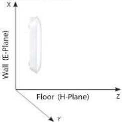 |  |  |
Antenna Pattern
| Orientation H-Plane E-Plane | ||
2.4 GHz Ceiling Mounted |  |  |
5 GHz Ceiling Mounted |  |  |
6 GHz Ceiling Mounted |  |  |
Regulatory Statements
Federal Communication Commission Interference Statement
This equipment has been tested and found to comply with the limits for a Class B digital device, pursuant to Part 15 of the FCC Rules. These limits are designed to provide reasonable protection against harmful interference in a residential installation. This equipment generates, uses and can radiate radio frequency energy and, if not installed and used in accordance with the instructions, may cause harmful interference to radio communications. However, there is no guarantee that interference will not occur in a particular installation. If this equipment does cause harmful interference to radio or television reception, which can be determined by turning the equipment off and on, the user is encouraged to try to correct the interference by one of the following measures:
- Reorient or relocate the receiving antenna.
- Increase the separation between the equipment and receiver.
- Connect the equipment into an outlet on a circuit different from that to which the receiver is connected.
- Consult the dealer or an experienced radio/TV technician for help.
Non-modifications Statement:
Any changes or modifications not expressly approved by the party responsible for compliance could void the user's authority to operate this equipment.
Caution:
This device complies with Part 15 of the FCC Rules. Operation is subject to the following two conditions:
(1) This device may not cause harmful interference, and (2) this device must accept any interference received, including interference that may cause undesired operation.
This device and its antenna(s) must not be co-located or operating in conjunction with any other antenna or transmitter except in accordance with FCC multi-transmitter product procedures. For product available in the USA/Canada market, only channel 1\~11 can be operated. Selection of other channels is not possible.
Note
The country code selection is for non-USA models only and is not available to all USA models. Per FCC regulations, all WiFi product marketed in the USA must be fixed to USA operational channels only.
RF Frequency Requirements
This device is for indoor use only when using all channels in the 5.15 to 5.25 GHz frequency range. High power radars are allocated as primary users of the 5.25 to 5.35 GHz and 5.65 to 5.85 GHz bands. These radar stations can cause interference with and/or damage this device. This device will not operate on channels which overlap the 5600-5650 MHz band.
It is restricted to indoor environments only.
IMPORTANT NOTICE:
Innovation, Science and Economic Development Canada (ISED) Statement:
This Class B digital apparatus complies with Canadian ICES-003.
Innovation, Science and Economic Development Canada (ISED) Statement:
This device complies with ISED licence-exempt RSS standard(s). Operation is subject to the following two conditions:
(1) this device may not cause interference, and
(2) this device must accept any interference, including interference that may cause undesired operation of the device.
Operations in the 5.25-5.35 GHz band are restricted to indoor usage only.
Radiation Exposure Statement
This equipment complies with ISED radiation exposure limits set forth for an uncontrolled environment. This equipment should be installed and operated with minimum distance 0.2 m between the radiator and your body.
Japan Voluntary Control Council for Interference Statement
Japan Voluntary Control Council for Interference Statement
This is a Class B product based on the standard of the VCCI Council. If this is used near a radio or television receiver in a domestic environment, it may cause radio interference. Install and use the equipment according to the instruction manual.
Product and Warranty Information
To find out more about D-Link Nuclias product or marketing information, please visit the website http://www.dlink.com or https://www.nuclias.com.
The D-Link Limited Lifetime Warranty information is available at http://www.dlink.com/warranty
VCCI-B
- HARDWARE OVERVIEW
- BASIC INSTALLATION
- SETUP WIZARD
- WEB USER INTERFACE
- ADVANCED SETTINGS
- TECHNICAL SPECIFICATIONS
- ANTENNA PATTERN
- REGULATORY STATEMENTS
- NUCLIAS CONNECT CONTROLLER INTRODUCTION
- NUCLIAS CONNECT KEY FEATURES
- PACKAGE CONTENTS
- NOTE
- SYSTEM REQUIREMENTS
- LEDS CONNECTIONS
- BASIC INSTALLATION HARDWARE SETUP
- CONFIGURE THE ACCESS POINT
- WIRELESS
- ACCESS POINT MODE
- WDS WITH AP MODE
- WDS MODE
- WI-FI PROTECTED ACCESS (WPA / WPA2 / WPA3)
- LAN
- IPV
- PERFORMANCE
- WIRELESS RESOURCE
- MULTI-SSID
- VLAN
- VLAN LIST
- PORT LIST
- ADD/EDIT VLAN
- PVID SETTINGS
- INTRUSION
- AP LIST: CLICK THE DROP-DOWN MENU TO SELECT ALL, VALID, NEIGHBOR, ROGUE, AND NEW
- SCHEDULE
- INTERNAL RADIUS SERVER
- ARP SPOOFING PREVENTION
- BANDWIDTH OPTIMIZATION
- SECTION 3 - CONFIGURATION
- CAPTIVE PORTAL
- AUTHENTICATION SETTINGS-WEB REDIRECTION ONLY
- AUTHENTICATION SETTINGS-USERNAME/PASSWORD
- AUTHENTICATION SETTINGS- PASSCODE
- AUTHENTICATION SETTINGS- REMOTE RADIUS
- AUTHENTICATION SETTINGS- LDAP
- AUTHENTICATION SETTINGS- POP
- LOGIN PAGE UPLOAD
- MAC BYPASS
- DHCP SERVER
- DYNAMIC POOL SETTINGS
- STATIC POOL SETTING
- CURRENT IP MAPPING LIST
- FILTERS
- WIRELESS MAC ACL
- WLAN PARTITION
- IP FILTER SETTINGS
- TRAFFIC CONTROL UPLINK/DOWNLINK SETTING
- QOS
- TRAFFIC MANAGER
- STATUS
- DEVICE INFORMATION
- CLIENT INFORMATION
- WDS INFORMATION PAGE
- CHANNEL ANALYZE
- STATISTICS ETHERNET TRAFFIC STATISTICS
- WLAN TRAFFIC STATISTICS
- LOG VIEW LOG
- LOG SETTINGS
- MAINTENANCE SECTION
- ADMINISTRATION
- LIMIT ADMINISTRATOR
- SYSTEM NAME SETTINGS
- LOGIN SETTINGS
- CONSOLE SETTINGS
- PING CONTROL SETTING
- LED SETTINGS
- DDP SETTING
- COUNTRY SETTING
- NUCLIAS CONNECT SETTINGS
- FIRMWARE AND SSL UPLOAD
- CONFIGURATION FILE UPLOAD
- TIME AND DATE SETTINGS
- CONFIGURATION AND SYSTEM
- SYSTEM SETTINGS
- HELP
- BASIC SETTINGS
- WIRELESS BAND
- NODE
- NETWORK NAME/SERVICE SET IDENTIFIER (SSID)
- SSID VISIBILITY
- AUTO CHANNEL SELECTION
- CHANNEL
- CHANNEL WIDTH
- AUTHENTICATION
- OPEN SYSTEM
- SHARED KEY
- STANDARDS
- NETWORK MANAGEMENT
- SECURITY
- WIRELESS FREQUENCY RANGE
- MAX POWER CONSUMPTION
- OPERATING VOLTAGE
- ANTENNA TYPE
- LEDS
- TEMPERATURE
- HUMIDITY
- CERTIFICATIONS
- DIMENSIONS
- FEDERAL COMMUNICATION COMMISSION INTERFERENCE STATEMENT
- NON-MODIFICATIONS STATEMENT
- CAUTION
- RF FREQUENCY REQUIREMENTS
- IMPORTANT NOTICE
- INNOVATION, SCIENCE AND ECONOMIC DEVELOPMENT CANADA (ISED) STATEMENT
- RADIATION EXPOSURE STATEMENT
- JAPAN VOLUNTARY CONTROL COUNCIL FOR INTERFERENCE STATEMENT
- PRODUCT AND WARRANTY INFORMATION
Brand : D-LINK
Model : DAP-E9560
Category : Access Point