
VLS 096A RF AC - Refrigerator VESTFROST - Free user manual and instructions
Find the device manual for free VLS 096A RF AC VESTFROST in PDF.
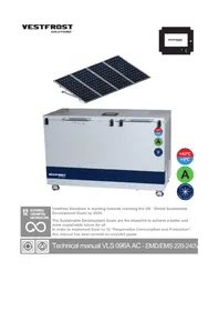


| Product Type | Refrigerator with freezer compartment (for vaccine storage) |
| Brand | VESTFROST |
| Model | VLS 096A RF AC |
| Power Supply | 220-240 V AC, 50/60 Hz |
| Refrigerant | R600a (isobutane), 50 g charge |
| Voltage Stabilizer | Built-in PPS_MFS, input range 110-285 VAC, output 200-245 VAC |
| Temperature Control | Electronic thermostat with separate sensors for refrigerator and freezer |
| Data Logger | Built-in, logs temperature at 15-minute intervals, accessible via USB-C |
| Display | EMS display with alarm codes and battery mode |
| Backup Battery | For data logger and EMS display during power loss |
| Defrost | Manual defrost; frost on evaporator is natural and should be removed during cleaning |
| Ice Bank | Provides holdover time calculation for vaccine compartment during power failure |
| Alarms | High/low temperature, lid open, sensor errors, low battery, and more |
| Locking | Cabinet lock with keys, keys to be kept out of reach of children |
| Safety | Flammable refrigerant R600a; service only by trained personnel; keep ventilation openings clear |
| Maintenance | Periodic cleaning of condenser coils, compressor grille, and drain filter |
| Spare Parts | Comprehensive spare parts list with item numbers (e.g., compressor, thermostat sensors, starting device) |
| Standards | Datalogger meets WHO/PQS/E006/DL01 requirements |
| Usage | Designed for vaccine storage, maintaining internal temperature between +2°C and +8°C |
| Installation | Requires clear ventilation openings, avoid trapping or damaging power cable |
Frequently Asked Questions - VLS 096A RF AC VESTFROST
User questions about VLS 096A RF AC VESTFROST
0 question about this device. Answer the ones you know or ask your own.
Ask a new question about this device
Download the instructions for your Refrigerator in PDF format for free! Find your manual VLS 096A RF AC - VESTFROST and take your electronic device back in hand. On this page are published all the documents necessary for the use of your device. VLS 096A RF AC by VESTFROST.
USER MANUAL VLS 096A RF AC VESTFROST


12
RESPONSIBLE
CONSUMPTION
AND PRODUCTION

Vestfrost Solutions is working towards reaching the UN - Global Sustainable Development Goals by 2030.
The Sustainable Development Goals are the blueprint to achieve a better and more sustainable future for all.
In order to implement Goal no 12 "Responsible Consumption and Production", this manual has been printed on recycled paper.


Technical manual VLS 096A AC - EMD/EMS 220-240V
WARNING
WARNING:
Keep ventilation openings in the appliance's cabinet or in the built-in structure clear of obstruction.
WARNING:
Do not use mechanical devices or other means to accelerate the defrosting process, other than those recommended by the manufacturer.
WARNING:
Do not damage the refrigerant circuit.
WARNING:
Do not use electrical appliances inside the storage compartment, unless they are of a type recommended by the manufacturer.

WARNING:
Danger: Risk of fire or explosion. Flammable refrigerant is used. To be repaired only by trained personnel.
WARNING:
When positioning the appliance, ensure the power cable is not trapped or damaged.
WARNING:
Do not locate multiple portable socket-outlets or portable power supplies at the rear of the appliance.
• Always keep the keys in a separate place and out of reach of children.
- Children should be supervised to ensure that they do not play with the appliance.
- This appliance is not intended for use by persons (including children) with reduced physical, sensory or mental capabilities, or lack of experience and knowledge, unless they have been given supervision or instruction concerning use of the appliance by a person responsible for their safety.
- Before servicing or cleaning the appliance, unplug the appliance from the mains or disconnect the electrical power supply.
- If the supply cord is damaged, it must be replaced by the manufacturer, its service agent, or similarly qualified persons in order to avoid a hazard.
- Frost formation on the interior evaporator wall and upper parts is a natural phenomenon. Therefore, the appliance should be defrosted during normal cleaning or maintenance.
- Please note that changes to the appliance construction will cancel all warranty and product liability.
- Do not store explosives, such as aerosol cans with flammable propellants in the unit.
Perform the following steps to prevent ESD damage:
- Use a wired ESD wrist strap that is properly grounded. Touching the chassis before handling parts does not ensure adequate ESD protection on parts sensitive to ESD damage.
- Handle all static-sensitive components in a static-safe area. If possible, use anti-static floor pads and workbench pads.
- When unpacking a static-sensitive component from its shipping carton, do not remove the component from the anti-static packing material until you are ready to install the component. Before unwrapping the anti-static packaging, ensure that you discharge static electricity from your body.
- Before transporting a static-sensitive component, place it in an anti-static container or packaging.

Contents
WARNING 2
Periodic preventive maintenance checks ...5
Complete spare part list VLS096A AC......6
Vital components 8
Health and safety guidance – Warning!......9
Wire diagram 11
Datalogger....19
Motor compartment 27
Thermostat sensor replacement for refrigerator 33
Thermostat sensor replacement for freezer 34
Battery replacement for connection board 43
EMS Display....44
Recycling procedures/Disposal .....54
Replacement of connecting board....56
Keep drain clean....57
Compressor replacement ....58
Periodic preventive maintenance checks
Daily Check:
Monitor Temperature
Internal lid is placed properly
Lid fits and lock tight to cabinet
Lid gasket not faulty.
Condensation build up in vaccine compartment.
Weekly maintenance:
Remove any water at the bottom of the refrigerator with a cloth.
Wipe of water droplets on the inside wall.
Monthly maintenance:
Clean grille for compressor compartment.
6 Month:
Clean condenser coils
Yearly maintenance:
Check electrical connections and components.
Check electrical connections, cables, wirings from PV panel system.
Regularly:
Clean Solar Panels
Check Solar Panels are not shaded at any time of the day
| PQS Code | Model PQS Performance | specificationsSpecification reference: | PQS Independent type-testing protocolProduct verification protocol: |
| VLS 096A RF SDD | E003/RF05.6 E003/RF05 | -VP.5 |
Complete spare part list VLS096A AC
Position Item number Item name
0061 6530120 Filter drier,
0087 0-6038175 Base plate fittings, complete
0129 8-036510018 Compressor - HXK80AT, Complete,
0550 6520510 Run cap. 4uF/4,8 receptacles
0898 7090546 Sensor kit, NTC, 1050mm, 1xTyco/2p Yellow
1141 6520533 Starting device PTC
2170 0-A9301260103 Distance piece
2172 7020486 USB-C cable, panel mount, 150mm, w/JST connector
2431 A915010 Lock complete snap locks and key
3104 7020562 PSU kit VDC-24060A0695, 2xRAST5/2p 350 +180mm
5000 3010049 Drain plug
5018 1510306
wheel with feet
5019 3010358 Plastic lid
5131 52009106004 Lid foamed without handle/hinges/to Cooler
5144 52009086050 Lid foamed without handle/hinges/Freezer
5402 1510059 Hinge
5402 1510135 Hinge with spring
5450 3011135-01 Top part for hinge cover
5451 3010032-01 Bottom part for hinge cover
5603 8471782 Handle
5606 8090054 Inlay for handle
5606 8090342-94 Inlay for handle, Vestfrost print
5682 1510255 Nikel-plated Key
5714 7060279
Overcurrent circuit breaker
5835 3011458-01 Filter for drain VLS
5883 7020545 Thyratron controller 230V PPS MFS-Lw v1.6
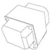
5884 7020546 Voltage stabilizer transformer Thyratron trafo 230V
5886 7021146 VLS controller (parrot) EMS level 2
5887 7060400 EMS battery - Litium
5888 7021143 Penguin VLS controller, EMS level 1 - AC
5907 3510535 Basket VLS096
5923 3510536 Bottom grating
1141 6520533 Starting device PTC
5883 7020545 Controller Thyratron
5884 7020546 Transformer Thyratron


Health and safety guidance – Warning!
Before any repair job be aware of following!
WARNING:
Before servicing or cleaning the appliance, disconnect it from power source.
WARNING:
Danger risk of fire or explosion. Flammable refrigerant used. To be repaired only by trained personnel.
(R600a)

Required basic tools
- Nose plier
- Screwdriver - size 1,0x6,0 + 0,6x3,5
- Torx screwdriver - size T10 + T20
- Clamp meter
- Multimeter
Proposed additional service kit/items
Sealing kit
Tar tape
Extra self-tapping screws

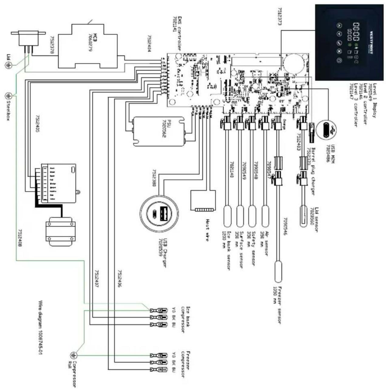
Wire diagram

Voltage stabilizers
Getting to know your appliance
Product features:
- Voltage stabilizer
• Voltage, Frequency and current supervisor - Intelligent ambient temperature protection
- Intelligent Time delay 3'30"+0"to30" random
- Surge protection
• Reconnecting Voltage Hysteresis - Zero Crossing
- Soft Start
• Zero current change over
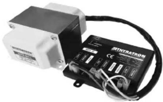
Electronic Control Unit - ECU & Trafo
(1): "OUT OF LIMITS" led (Red) (3), (6): Mounting points (2): "OPERATION" led (Green)
(4): Fast on terminals (5): Connection cables - Fast On female terminal


LED - Indication
The PPS_MFS is maintenance-free and is made up of non-repairable / refurbishable parts. In the event of a failure of the PPS MFS, both ECU and Trafo have to be replaced with new, unused units. Partial replacement is not advisable.
| Red led “OUT OF LIMITS” | Green led “OPERATION” | EVENT | Actions |
| Off | On | Normal operation | |
| Blink Slow (1Hz) | Off | - Start-Up delay- Voltage out of limit | - Wait until the output is enabled (max 5mins).- If the output was not enabled in 5 mins, the voltage being supplied to the stabilizer is out of limits. Check the input voltage. |
| Blink Fast (2Hz) | Off | Frequency out of limits | - The frequency of the voltage being supplied to the stabilizer is out of limits. Check the input frequency. |
| Blink Slow (1Hz) | Blink Slow (1Hz) | Temperature out of limits | - Check for hot spots near to the ECU. |
| Off | Off | - No input power- Stabilizer failure | - Check if mains power Turning On- If mains power is on, the stabilizer needs to be replaced (Trafo and ECU). |
| Blink Slow (1Hz) | On | Short circuit detected | - Disconnect mains power and check for a short circuit in the refrigerator.- In order to reset the voltage stabilizer after a short circuit detection ( 10xIrated ), disconnect mains power, wait for at least 20 seconds and reconnect* the refrigerator (power cycle). The output is reconnected automatically with a time delay.*Warning: Reconnection of the refrigerator to mains power when a short circuit has been detected, must be done after the failure has been resolved. |
Voltage stabilization
| Output Voltage Limits | |
| The stabilizer ensures that the output voltage will remain inside the output limits, if the input voltage fluctuation is between the input limits | 200 VAC ±1% (195.5 VAC @ Lowest Input Voltage) / 245VAC ±1% |
Voltage & frequency monitoring
| Input Voltage Frequency | ||
| PPS_MFS-Lw monitors the voltage and frequency of mains power and cuts off the output, whenever the values of mains power goes out of limits. | 110 -285VAC 47 | -63 Hz |
| Over current protection | |||
| Time Reaction | |||
| PPS_MFS-Lw monitors the output current and cuts off the output when the values goes out of limits. | 1.5 x Irated< 120 Sec | 7.2 x Irated< 10Sec | 10 x Irated< 0.1 Sec |
Specifications
| PPS_MFS-Lw Series[v1.6]: | PPS_MFS-1LW[v1.6] | PPS_MFS-2LW [v1.6] | ||||||
| PPS MFS-xxxLw Series(xxx: 070, 085, 100, 150, 200) | 070 | 085 | 100 | 150 | 200 | |||
| Input | Continuous Voltage withstand range (@ 25°C) | 60 - 500 VAC | ||||||
| Nominal Input Voltage | 230VAC | |||||||
| Voltage regulation range | 110 - 285 VAC | |||||||
| Nominal Frequency / Frequency limits | 50 or 60 Hz / 47 - 63Hz | |||||||
| Output | Nominal Output Voltage | 230VAC | ||||||
| Voltage range | 200 VAC ±1% (195.5 VAC @ Lowest Input Voltage) - 245 VAC ±1% | |||||||
| Nominal Frequency / Frequency limits | 50 - 60 Hz / 47 - 63Hz | |||||||
| Current Capacity I_rated (A)( Continuous Operation (43°C) @ Low Voltage ) | 3.2 | |||||||
| Overcurrent Protection | 1.5 x I_rated< 120 Sec / 7.2 x I_rated< 10 Sec / 10 x I_rated<100 mSec | |||||||
| Automatically Reconnection Time Delay /Start-Up Time | 4'30'' + 0'' to 30'' random /Zero Time on Production Line for first 30 minutes continuous operation of life cycle | |||||||
| IP Class | IP4X | |||||||
| Insulation Class (transformer windings) | Class H (180°C) | |||||||
| Ambient Temperature range (use/transport, storage) | t_amin-5 to t_a+43°C during use /-30°C to +70°C when the device is inactive | |||||||
| Ambient Humidity range (transport, storage, use) | 5 - 95% RH, non-condensing | |||||||
| Overvoltage Category and Pollution Degree | OVG: III, P3 | |||||||
| Plastic Housing | UL94 V-0 Flame Retardant, GWT 850°C | |||||||
| Relays | Relay lifetime cycles 350,000, Explosive Atmospheres Certified (IEC 60079-15 type of protection "n") | |||||||
| Connections | Fully Insulated Fast On 6.3mm x 0.8mm | |||||||
| Cable Harness - Lengths | 250 mm /550mm/1000mm | |||||||
| Overall Dimension /Total weight | ECU | 114 x 121 x 32.5±1.0mm /0.267 ±0,1kg | ||||||
| Trafo | - Standard installation- Vertical installation | 108.5x94.5x131±1.0mm4.02±0.1kg | ||||||
Safety instructions - Installation
What this chapter contains
This chapter contains the safety instructions which you must follow when installing, operating and servicing the Power
Protector Stabilizer MFS. If ignored, physical injury or death may follow and/or damage may occur to the PPS MFS. Read the safety instructions before you work on the unit. These warnings are intended for all who work on the PPSMFS, or cable.
WARNING! The work described in this chapter may only be carried out by a qualified electrician. Ignoring the safety instructions can cause physical injury, death or/and damage to the equipment. Make sure that the device is disconnected from the mains (input power) during installation.

Beware of hot surfaces. Some such as transformer, may remain hot for a while after disconnection of the electrical supply.

Electrostatic discharge warning warns of electrostatic discharge which can damage the equipment.
- Only qualified personnel are allowed to install and maintain the PPS_MFS.
- The ECU contain components sensitive to electrostatic discharge. Do not open the plastic enclosure or touch the fast-on terminals.
- PPS MFS is intended to be built into commercial refrigeration appliances or other enclosures that provide protection against certain external influences and in any direction, protection against direct contact and electric shock. It shall be installed in an area where it is inaccessible without disassembly of the enclosing area.
- Never work on the PPS_MFS or its wiring when mains power is applied. Always ensure that the voltage between the device input terminals, labeled INPUT and NEUTRAL, is close to 0V, by measuring with a multimeter (impedance of at least 1 MOhm). Externally supplied control circuits may cause dangerous voltages on the device even when the mains power on the drive is switched off.
- Do not perform any insulation or voltage withstand tests on the device.
- When reconnecting the wiring, always check that the Phase - Neutral order is correct.
- Do not change the electrical installations of the PPS_MFS. Changes may affect the safety performance or operation of the device unexpectedly. The customer is responsible for all customer-made changes.
- Make sure that dust from boring and grinding does not enter the drive when installing. Electrically conductive dust that enters the unit may cause damage or malfunction.
- Do not fasten the device through welding.
Note:
-
Traces of rust on sharp edges and any yellowish film (removable by rubbing) that may appear on outer surfaces of the autotransformers iron cores due to certain conditions (marine environments, high humidity, rain, snow, wind, dust, pollution, ultraviolet rays, and sea salt), have no effect in high reliability performance and lifetime of the product.
-
The fast-on terminals on the device are at a dangerously high voltage when the input power is on.
Installation and maintenance work
- The Voltage stabilizer consist of two parts, the Electronic Control Unit (ECU) and the Autotransformer (Trafo). The ECU and the Trafo of the device is delivered in separates cardboard box. The type, size and material of the package depend on the frame size of the Autotransformer.
- The parts of the Voltage stabilizer must be connected by using fast-on terminals taking in care the coloring code of the cables and ECU.
- Confirm compatibility with connection terminals as well as insulation. The connectors are Fast On terminals 6.3x0.8mm


Before powering the device:
- Confirm color coding between ECU and Autotransformer
Fuse trouble shooting
How to determine why the thermal magnetic breaker nuisance trips?
The thermal magnetic breaker is installed to protect the build-in voltage stabilizer.
Cause: Circuit breakers trip.
Resolution:
-
First, determine if the breaker trips on startup or if it trips after running for a while.
-
If it trips at start-up but doesn't do it repeatable, it is caused by inrush current to either the voltage stabilizer or the compressor. Resetting the breaker will have no harm on the appliance
-
If it trips at start-up and does it multiple times, there is a short circuit within the appliance and a service technician should be contacted.
-
If it breaks after some time, the appliance is overloaded. Ensure that the condenser and engine room are clean and give the unit some minutes to cool down before resetting the fuse. The start electronic on the compressor can also be faulty causing the compressor to run on the start condenser constantly.
Maintenance, diagnostic and repair procedures
The Voltage stabilizer is maintenance-free and is made up of non-repairable / refurbishable parts. In the event of a failure of the Voltage stabilizer, both ECU and Trafo have to be replaced with new unused units. Part replacement is not advisable.
Storage
Should not be stored or and transport in high temperature or high humidity condition. Usage, beyond the specified shelf life could compromise product long term reliability. The suitable condition is +5 to +35°C and less than 95% RH in Relative Humidity indoor.
Applicable Ambient temperature and humidity range during transport and storage: -30 to +70°C, 5 to 95% RH.
End of life resource recovery and recycling procedures.
Disposal of Old Electrical & Electronic Equipment (Applicable in the European Union and other European countries with separate collection systems).

This symbol on the product or on its packaging indicates that this product shall not be treated as household waste. Instead it shall be handed over to the applicable collection point for the recycling of electrical and electronic equipment. By ensuring this product is disposed of correctly, you will help prevent potential negative consequences for the environment and human health, which could otherwise be caused by inappropriate waste handling of this product.
Generale description
The temperature controller has three temperature controllers with their own setpoint and hysteresis.
Relay 1 is controlled by ice bank sensor. Relay 2 is controlled by freezer sensor. Heater is controlled by surface sensor.
Controlling loads
Compressor
The regulation is performed according to the temperature measured by the thermostat probe with a positive differential from the set point: if the temperature increases and reaches set point plus differential the compressor is started and then turned off when the temperature reaches the set point value again.

Heater
The regulation is performed according to the temperature measured by the thermostat probe with a negative differential from the set point: if the temperature decreases and reaches set point minus differential the heater is started and then turned off when the temperature reaches the set point value again.
The heater is PWM controlled to ensure constant power independent of the supplied voltage. The heater PWM percentage is calculated as ( )

Regulation frequency
The measurement frequency of all sensors is 1 Hz. The compressors are also controlled at a 1 Hz rate, but are prevented to start based on the (AC) parameter.
Datalogger
Datalogger
The controller has a built-in data logger, fulfilling the requirements of WHO/PQS/E006/DL01.
The logger is primarily tasked with maintaining relative time, recording appliance data
objects, generating and recording logger data objects, and making that data available in a standardized way to other equipment monitoring devices and systems.
All data is logged in a 15-minute interval, except lid sensors which are logged instantly.
Data for the last hour is logged in a separate file in a 10-second interval for troubleshooting.
The data can be accesses by the USB-C port.
Time keeping, stand alone
The logger will keep its own relative time starting from the production date. When the battery is drained or the device is turned off, the time keeping will pause and will automatically restart when the device is turned on.
Time keeping, interanl connection to level 3
When a level 3 device is connected to the internal connector, the time will be set based on the clock from GPS or 4G connection.
Max and min Temperature memorization
It is possible to see that minimum and maximum temperatures for the last 30 days.
How to see the min temperature
- Press and release the
key. - The "Lo" message will be displayed
followed by the minimum temperature recorded.
- By pressing the waiting 5s the restored.

again or byal display will be
How to see the max temperature
- Press and release the

-
The "Hi" message will be displayed followed by the maximum temperature recorded.
-
By pressing the waiting 5s the restored.

again or byal display will be
How to reset the max and min temperature recorded
- Hold press the

3s, while the max. or min temperature is displayed. (rSt message will be displayed)
- To confirm the operation the "rSt" message starts blinking and the normal temperature will be displayed.
Alarms
In case of an alarm, the display will display the alarm code and the buzzer will sound an alarm.
An alarm can be muted by pressing any button. The display shall still display the alarm code.
During alarm, the display will alternate between the alarm code and the temperature.
Pressing the bu

Pressing the button after muting, will reset the alarm.
During battery operation, only high and low surface temperature sensor alarms will be set. (if the temperature is high, there is no longer a charged ice bank and the remaining battery capacity can be used to send alarms).
List of alarms and error codes
The following alarms are monitored and logged:
| Alarm type Thres- | hold | Dura-tion | Blanking period | List of Error Codes |
| LoA (low temperature) AL1 | Ad1 Ab1 A | - Vaccine temp. | sensor error | |
| HiA (high temperature) AH1 | Ad2 Ab2 B | - Ambient temp. | sensor error | |
| Lid 1 open L1T L1A C - Ice | bank temp. | sensor error | ||
| Lid 2 open L2A D - Surface | temp. | sensor error | ||
| Low battery datalogger Lbd | E - Freezer temp. | sensor error | ||
| Low battery EMS Lbe F - Vaccine comp. | door malfunction | |||
| Real time clock battery low | G - Freezer comp. | door malfunction | ||
| High temperature freezer | H - Power measure-ment error | |||
| DC barrel plug fault | I - Compressor 1 malfunction | |||
| Heating cable short circuit | J - Compressor 2 malfunction | |||
| Heating cable open circuit | K - Fan malfunction | |||
| Fan blocked | Z - Missing/incomplete data records |
Blanking period is the time from the unit is turned on until the alarm is activated, giving the refrigerator time to cool down. This is done to avoid false alarms.
Battery mode
The controller will run on battery mode when the supply voltage is too low.
When the controller is running on battery, all regulation loops are deactivated. The hold over time calculation is still active.
The displays are turned off.
By pressing the button, the temperature of the refrigerator is shown for 3 seconds. Pressing the button again within 3 seconds will show the remaining hold over time. The symbol will also light up.
The battery capacity is only designed to show a minimum number of temperatures/ hold over time. If the display is used excessively during battery mode, the battery might not last long enough to log the vaccine temperature.
Display turn on is logged.
Long press plus confirmation press will put the device on standby/wake the device.
If external power is supplied through the USB-C port, the data logger shall wake up
and present its file system. The symbol will flash to indicate data transfer.
Hold over time
The controller can estimate the time remaining before the vaccine compartment gets too warm. The estimate is conservative, but based on idealized conditions. The estimate will be affected by, among others, how much the refrigerator is filled and the installation location.
Fault handling
If the ice bank sensor is defective (open line or short circuit) the compressor will stop, and the display will show P3A (sensor 3 alarm).
If the surface sensor is defective (open line or short circuit), both the compressor and the heater will stop, and the display will show P1A (sensor 1 alarm).
If the surface sensor is below (LST), the compressor is switched off and the display will show LST.
If all other sensors fail, the display will show PxA (sensor x alarm), but the control will continue.
All faults must be logged.
Safety thermostat
The controller has an analogue safety thermostat on the circuit board. The safety thermostat prevents the compressor from running in case of a fault in the heating circuit. The set-point for the safety thermostat is set by a DIP switch. It is not possible to see if the safety thermostat is active.
Production mode
The controller has an analogue safety thermostat on the circuit board. The safety thermostat prevents the compressor from running in case of a fault in the heating circuit. The set-point for the safety thermostat is set by a DIP switch. It is not possible to see if the safety thermostat is active.
Turning the appliance on and off
The appliance is designed to be always on, but can be switched off if necessary.
The controller is designed for both AC and SDD. The user does not need to know the difference as the controller will handle it automatically.
Whenever the appliance is turned on, the controller and datalogger will turn on
AC mode
When the MCB is switched on, the voltage stabilizer will start a delay timer (approximately 5 minutes) before switching on the power. If the MCB is switched off or the supply voltage is out of range, the data logger will continue running on internal battery. When eventually the battery is drained, the datalogger will also turn off.
When the supply voltage is back in range, the controller and datalogger continue running.
SDD mode
The supply voltage from the PV cells needs to be above a certain threshold before the controller is turned on. This is defined on the DOV parameter.
The supply voltage from the PV cells needs to be above a certain threshold before the compressor is turned on. This is defined on the DOV parameter. If the supply voltage drops below the CSV voltage the compressor output is turned off and is not allowed to turn on again before after a blanking time, defined by the CBT parameter.
Turning the appliance off
If the appliance needs to be turned off, it is important to switch off the datalogger.
Level 1 display: Long pressing the and a short confirmation press

Level 2/3 display:
It is important to switch off the MCB and disconnect the appliance when it is switched off. When power is reapplied, the controller will automatically restart
Parameter menu
The parameter menu Includes all the parameters of the instrument.
How to enter the parameter menu
To enter the parameter menu, you need to have a valid user ID and passcode.
All changes done in the technical menu will be logged with the user ID
-
Enter the hidden menu by pressing the √ + keys for 3s (the "clock" LED starts blinking).
-
The freezer display will show "user".
-
Use the and buttons to
select you user ID and press the button.

-
The freezer display will show "pass"
-
Use the and buttons to select the first digit in your passcode and confirm with the button.
-
Use the and buttons to select the send to forth digit in your passcode and confirm with the button.
-
The freezer display will show the parameter name and the refrigerator display will show the value of the parameter.
-
Select the required parameter.
-
Press the ⚙️ key to display its value
-
Use ⚠️ or ⚡️ to change its value.
-
Press to store the new value and
move to the following parameter.
To exit: Press ☒ or wait 30s without pressing a key.
NOTE: the set value is stored even when the procedure is exited by waiting the time-out to expire.
User ID and passcodes are stored in a file access by the USB port. The default user ID is 1 and the passcode is [1 1 1 1]. It is strongly recommended to change the default passcode.
Technical menu
The technical menu allows the user to check the input values and control the outputs. When entering the technical menu.
How to enter the technical menu
-
Enter the hidden menu by pressing the √ + ↗ keys for 3s (the “compressor” LED starts blinking).
-
Released the keys, then push again the + keys for more than 7s. The TEC label will be displayed. immediately followed by P1 temperature.
-
The freezer display will show the input/output the refrigerator display will show the value of the input/output.
-
Use or to change input/output.
-
The outputs can be turned on/off (toggle) by pressing the button.
-
The input/outputs are listed in this order: P1, P2, P3, P4, P5, P6, P7, HUM, RE1, RE2, HEA, VOL, BAT,
-
To exit: Press pressing a ke

ait 15s without
- All outputs are returned to the same state as before the technical menu was entered.
Parameter
Regulation
- SpH Set point heater: (-25°C / 25°C) Set point for the heater, controlled by the surface temperature sensor
- HyH heater Differential: (0,1 / 25,5°C) Intervention differential for heater set point. Heater Cut IN at Set Point. Heater Cut OUT at Set Point – differential (HyH).
• HSV Heater operating voltage: (0/100V) The voltage which the PWM controller will try to reach on the heater output. - SpC Set point compressor: (-25°C/25°C) Set point for the compressor, controlled by the ice bank temperature sensor
- HyC compressor Differential: (0,1 / 25,5°C) Intervention differential for set point. Compressor Cut IN is SpC + differential (HyC). Compressor Cut OUT is when the temperature reaches the set point.
- SpF Set point freezer compressor: (-25°C/25°C) Set point for the compressor, controlled by the freezer temperature sensor
- HyF freezer compressor Differential: (0,1 / 25,5°C) Intervention differential for set point. Compressor Cut IN is SpF + differential (HyF). Compressor Cut
OUT is when the temperature reaches the set point.
- Lpf Low pass filter: (0,01 / 1,00) scales how much of the stored temperature is updated with the measure temperature. T_stored = Lpf x T_meas + (1-Lpf) x T_stored. Temperatures are measured with a sample frequency of 1 Hz.
- O1 Thermostat(surface) probe calibration: (-12.0 / 12.0°C) allows to adjust possible offset of the surface probe.
- P2P Vaccine probe presence (P2): 0= not present:, no alarms 1= present.
- O2 Vaccine probe calibration (P2): (-12.0 / 12.0°C). allows to adjust possible offset of the vaccine probe.
- O3 ice bank probe calibration (P3): (-12.0 / 12.0°C). allows to adjust possible offset of the ice bank probe.
- P4P Ambient probe presence: 0= not present:, no alarms 1= present.
- O4 Ambient probe calibration: (-12.0 / 12.0°C) allows to adjust possible offset of the ambient probe.
- P5P Compressor probe presence: 0= not present, 1= Fan is controlled by FoM
- O5 Compressor probe calibration: (-12.0 / 12.0°C) allows to adjust possible offset of the ambient probe.
- P6P Freezer probe presence: 0= not present:, no alarms, the freezer display is not active 1= present., the freezer control is active.
-
O6 Freezer probe calibration: (-12.0 / 12.0°C) allows to adjust possible offset of the freezer probe.
-
P7P Humidity probe presence: 0= not present:, no alarms 1= present.
- O7 Humidity probe calibration: (-12.0 / 12.0 %rH) allows to adjust possible offset of the humidity probe.
- AC Anti-short cycle delay: (0÷50 min) minimum interval between the compressor stop and the following restart.
- R2D Relay 2 delay: (0/60 min) Minimum time between relay 1 and relay 2 is activated
- LST Low Surface Temperature: (-12.0 / 12.0°C). If the surface temperature sensor is below this temperature, the compressor is switched off.
Freezer regulation
- FrC Freezer combi: 1= independent freezer control controlled by (SpF) and (HyF). 0 = valve control of freezer. Main compressor is controlled by both ice bank and freezer temperature sensor. Freezer relay is activated if only freezer requires cooling and deactivated if ice bank requires cooling.
Freezer regulation
- FoM Fan operating mode: 0 = no fan; 1 = fan on when compressor is on (On/off control); 2 = fan controlled by compressor temperature sensor (PWM control).
- If (FoM) = 2: If compressor temperature is below (FTi), fan is stopped. If compressor temperature is above (FTa) fan is running at maximum speed (FSa). If compressor temperature is between (FTi) and (FTa) the fan speed is controlled linear between (FSi) and (FSa).
- FTi Fan minimum temperature: (0/100°C)
- FTa Fan maximum temperature: (0/100°C)
• FSi Fan minimum speed: (0/100%)
• FSa Fan maximum speed: (0/100%)
Fan control
- FoM Fan operating mode: 0 = no fan; 1 = fan on when compressor is on (On/off control); 2 = fan controlled by compressor temperature sensor (PWM control).
- If (FoM) = 2: If compressor temperature is below (FTi), fan is stopped. If compressor temperature is above (FTa) fan is running at maximum speed (FSa). If compressor temperature is between (FTi) and (FTa) the fan speed is controlled linear between (FSi) and (FSa).
- FTi Fan minimum temperature: (0/100°C)
- FTa Fan maximum temperature: (0/100°C)
• FSi Fan minimum speed: (0/100%)
• FSa Fan maximum speed: (0/100%)
Alarms
- Li1 Lid sensor 1: 0= not present:, no alarms 1= MEMS sensor, 2 = mechanical sensor
- Li2 Lid sensor 2: 0= not present:, no alarms 1= present
- L1A Lid 1 alarm time: (0/60 min) Time before an open lid alarms is activated
- L2A Lid 2 alarm time: (0/60 min) Time before an open lid alarms is activated
- L1T Lid 1 threshold: (0/90°) Threshold before the lid is detected open
- L1p Lid sensor 1 polarity: 0= lid open when contact is open, 1=lid open when contact is closed.
- L2p Lid sensor 2 polarity: 0= lid open when contact is open, 1=lid open when contact is closed.
GB
- AH1 Alarm high temperature: (0/10°) activates buzzer and writes "HiA" in display. Acknowled by any button.
- AL1 Alarm low temperature: (0/10°) activates buzzer and writes "LoA" in display. Acknowled by any button.
- Ad1 Alarm delay high temperature: (0/1000 min) delay before high temperature alarm is acticated
- Ad2 Alarm delay low temperature: (0/1000 min) delay before low temperature alarm is acticated
- Lbd Low battery alarm datalogger: (0/100%) low battery capacity alarm
• Lbe Low battery alarm EMS: (0/100%) low battery capacity alarm
Hold over time calculation
- Cle C_Leackage: Leakage value for hold over calculations
- Cic C_ice: latent heat constant for the ice bank: (0-1000 kilojoules per kg) default 334
- Mic M_ice Mass of ice in kg: (0-1000 kg)
- Phe P_heater power of heater: (0-1000 W)
• COP compressor performance: (0,1/10,0)
Operation condition
- DOV Datalogger operating voltage: (0/100 V) Minimum supply voltage for turning the controller and datalogger on.
-
COV Compressor operating voltage: (0/100 V) Minimum supply voltage before the compressor is turned on
-
CBT Compressor blanking time: (0-120 min) If before the compressor can be turned on again if the supply voltage drops.
- CSV Compressor stop voltage: (0/100 V) If the supply voltage drops below this value, the compressor must wait for CBT time before it is allowed to start again.
Other
- EHI Energy harvest low voltage: (0/100v) The supply voltage must be above this value to activate output
- EHh Energy harvest high voltage: (0/100v) The supply voltage must be below this value to activate output
- EHh Energy harvest high voltage: (0/100v) The supply voltage must be below this value to activate output
Motor compartment
How to get access to the motor compartment.

- Use a screwdriver to unlock all 7 clamps.


3.Gently pull the compressor grille.2. Unlock all 7

How to get access to the motor compartment on the back

- Use a screwdriver to loosen all 4 screws.
Voltage Stabilizer ECU replacement
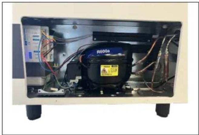
- The Voltage stabilizer is placed on the left side of the compressor compartment
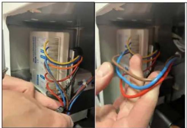
- Remove the wires by pulling on the terminal housing, not on the wires.

- Remove the wires gently.
- Take the Voltage stabilizer. See the next pages how to loosen the.

- Ensure that the bracket aligns as shown in the next picture

- Make sure the tap fits precisely in the marked bracket, neither too loose nor too tight.
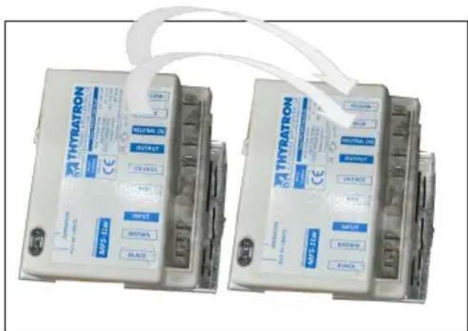
- Exchange the wires from the old ECU to the new.
Transformer replacement

- The transformer is placed on the left side of the compressor compartment behind the Voltage stabilizer

- be aware to loosen the screw from the ground wire.

- Loosen the screws from voltage stabilizer controller/transformer bracket

- Remove the stabilizer controller/transformer bracket, by squeezing the sides of the clamps that hold the wire connections, then pull the plug and socket apart
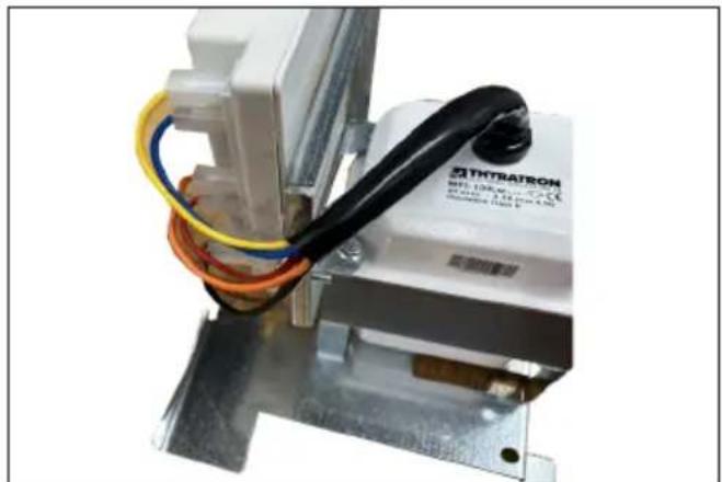
- Untighten the 8mm bolt connecting the stabilizer controller to the bracket

- Take apart the controller and transformer.
Starting device replacement

Front with terminals.

Right side view
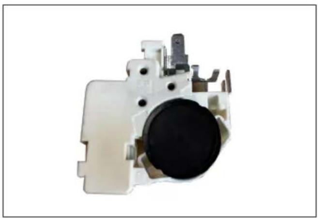
Left side view.

The starting device is mounted on the left side of the compressor.
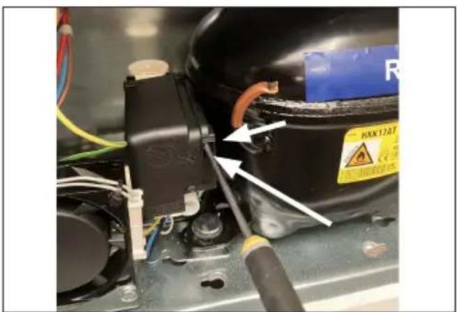
- Dismount the cover by pushing the cover lock from right to the left with a flat screw driver.
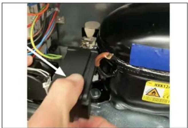
- Pull out the cover
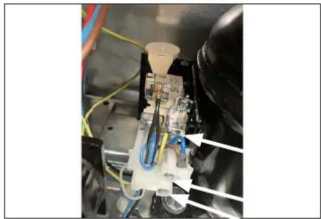
- Use a screw driver to lose 3 x screws.

- Use a screwdriver to loose the starting device from socket and pull.
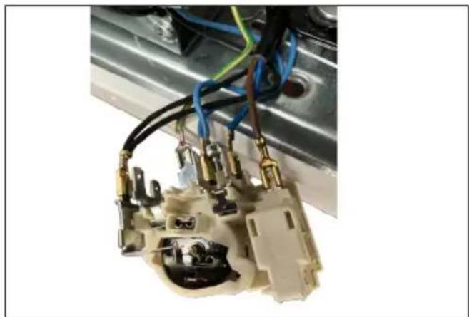
- Use a nose plier to unmount the wire sockets from starting device.
- Exchange the wires 1/1 from the old starting device to the new one.

Run capacitor replacement

The run capacitor is placed in the left side of the compressor compartment, fixed to the compressor bracket.

- Dismount the cover by pushing the cover lock from right to the left with a flat screw driver.

- Pull out the cover to remove

- Loosen the screw for cord relieve and pulle out the wire. The capasitor kan be remounted in reverse ordrer.

- Flip out the clamp to free the capacitor from the bracket.

Thermostat sensor replacement for refrigerator

The thermostat sensor is placed inside the compartment of the appliance.

1: Dismount the temperature sensor cover by loosen the 2 x torx screws – size 10.

- Take it out gently, remove the wire and the sensor from the cover.

- In Compressor compartment, remove black sealing, and gently pull the white wire until the probe is visible.
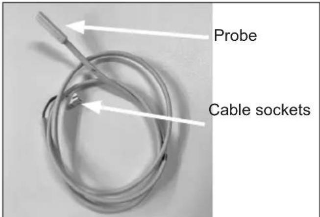
- The thermostat sensor comes with probe, wire and cable socket.

- IMPORTANT! When re-mounting the new thermostat sensor remember to properly seal the wire feed through.
Thermostat sensor replacement for freezer

The thermometer sensor is placed inside the compartment of the appliance.
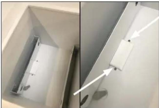
1: Dismount the temperature sensor cover by loosen the 2 x torx screws – size 10.

- Take it out gently, remove the wire and the sensor from the cover.

- In Compressor compartment, gently pull the white wire until the probe is visible.

- Gently pull the white wire until the probe is visible.

- The thermostat sensor comes with probe, wire and cable socket.
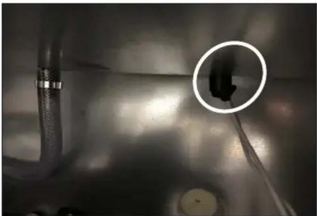
6. IMPORTANT!
When re-mounting the new thermostat sensor remember to properly seal the wire feed through.

7. IMPORTANT!
When re-mounting the new thermometer make sure the wire sealing plug is placed properly
How to access the electrical box

- Dismount 6 x Torx 20 screws and unmount the junction box lid

- Be careful with the lid as the ground wire is attached to the lid

- Loosen the ground wire from the lid
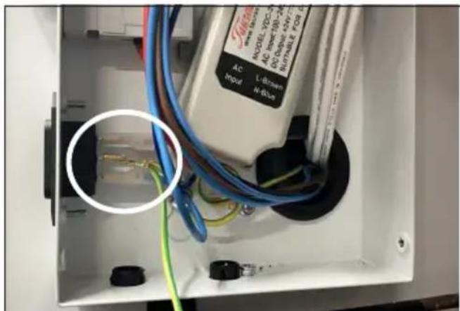
- Loosen the ground wire from the plug

EHC- USB Charging ports replacement


- Remove the wires.


- Take it out and put a new one in. 3. Loosen bol


- It must look that this
- Tighten it again and put the wires back and be aware of the red and black position is placed right.
5V monitoring power replacement

- Press the rubber grommet gently out of the socket using your finger

- Press the rubber grommet gently out of the socket using your finger

- Pull gently the wire out of the connection board socket

- 5V monitoring power socket ready for mounting replacement wire
M2M - Logger data stick replacement

- Loosen the wire before you loosen the USB stick

- Remove the wires.

- Loosen bolt

- Remove the USB C outlet connector, replace with new one

- Tighten it again and put the wires back and be aware of the red and black position is placed right.

- It must look that this
Circuit breaker replacement

You have to remove the power supply to changes the circuit breaker

- Loosen the screws so the bracket can be removed


- Replaced it with a new circuit breaker2. Move th

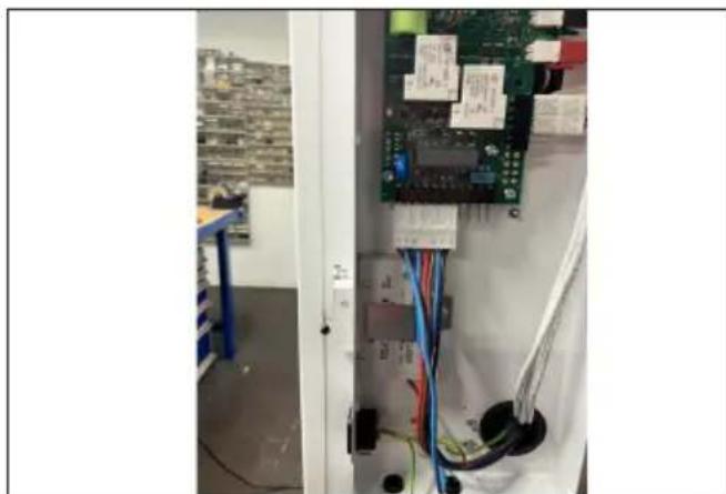
- Be aware of it must be placed right 4. Be aware
Power supply replacement

The power supply is secured by 2 screws 5,5 mm
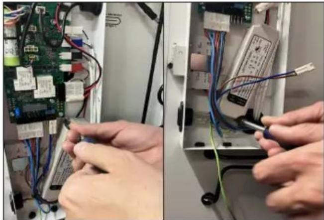
- Loosen the 2 Torx screws

- Gently disconnect the two marked power sockets from Connection Board

- Power sockets successfully removed.

- Mount the new power supply - use reverse instructions
Replacement of connecting board

- Access electrical components Dismount 6 x Torx 20 screws and unmount the junction-box lid

- Be careful with the lid as the ground wire is attached to the lid

- Loosen the ground wire from the lid

- Used Torx 20 to loosen the 4 screws

- By hand gently press the lock function on both sides of the power wires plugs and slide backwards

6.
Battery replacement for connection board

- Battery position 2. Cut the strip off

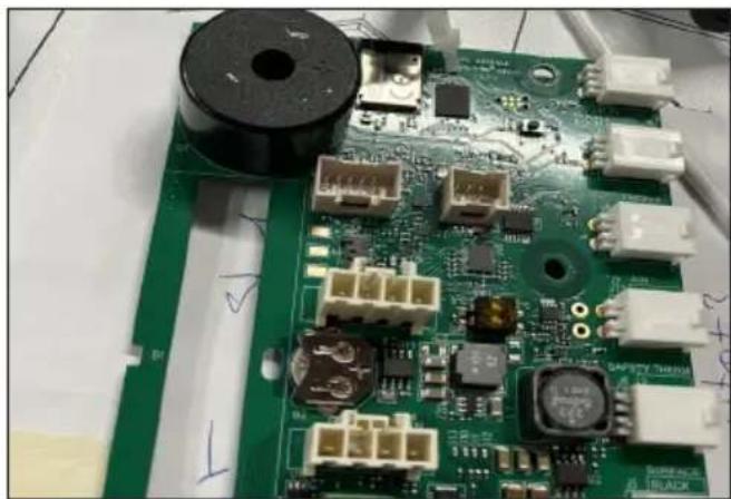

- By hand gently pull the wire out 4. The battery can be change

- By hand gently put the wire in place. 4. The battery has been changes make sure to fasten it again

EMS Display
Before any repair job be aware of following!

WARNING:
Before servicing or cleaning the appliance, disconnect it from power source.
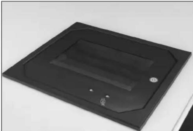
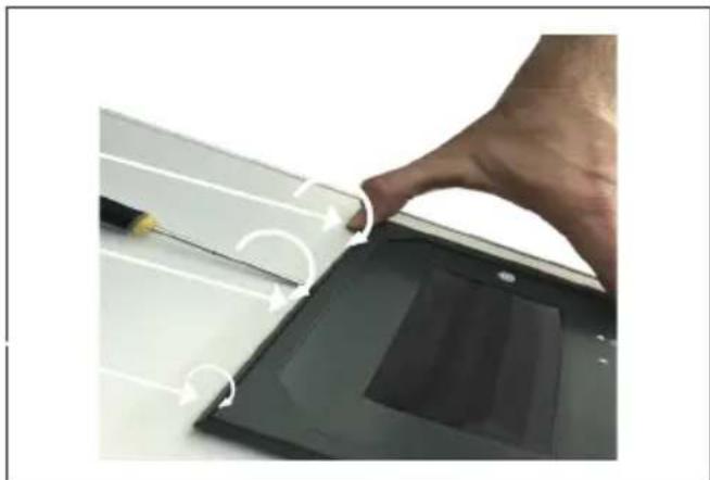
- Gently place a small screwdriver, under the top part of the display cover and twist the screwdriver to unlock the 3 fixing points

- To unmount the display unfasten the 4 Torx 20 screws

- By hand gently bring up the display then-tilting it to the left

- Display is off

- Loosen the 2 x wire plugs from the control unit by clicking on the side

- Replace the control-unit/display
Battery replacement for EMS

- Battery position 2. Power wire connection to electronic control unit


- By hand gently press the lock function on both sides of the power wire plug and slide backwards

- The power wire is loose
External antenna


- Place the cable from the external antenna

- The external antenna is to be wired from the back of the unit

- The cable is being gathered. The cable tie is being tightened around the bundled cable to keep it organized and fixed in place.

- Place the external antenna as high up as possible in order to receive the best GSM signal available

Compressor replacement
Procedure of compressor switch.
1: WARNING! Drain coolant R600a from refrigeration system by vacuum suction.
2: IMPORTANT! Blow refrigeration system with NO/Nitrogen
3: Cut
A: Suction and pressure tube
B: Capillary tube
C: Dry filter
4: Dismount starting device
5: Dismount old compressor
6: Insert new compressor
7: Solder
A. Suction and pressure tube
B. Capillary tube
C. Dry filter
8: Install starting device
IMPORTANT! When solder copper tubes to iron tubes use silver tin
Filling of new refrigerant
9: Drain refrigeration system by vacuum suction
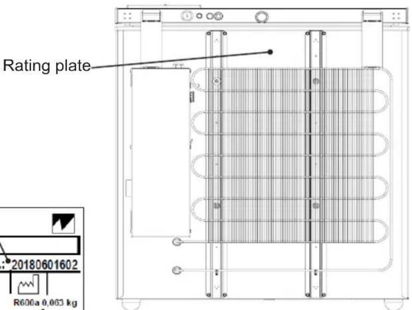
10: Check type sticker for required amount of R600a to fill on refrigerant system
⚠️ Important Safety Note
R600a (isobutane) is highly flammable. Work only if you are a trained technician, in a well-ventilated area, with no ignition sources. Use tools rated for hydrocarbon refrigerants.
Safety First
• Work only in a well-ventilated, spark-free area.
- Use only tools rated for flammable refrigerants.
- Wear goggles, gloves, and anti-static shoes.
- Never overcharge — hydrocarbons are highly sensitive to charge weight.
Service Instruction: Recharging a Vaccine Refrigerator with R600a: Check the Rating label
1. Preparation & Safety
- Tools and equipment needed:
- Manifold gauge set (rated for hydrocarbons)
- Vacuum pump
• Electronic refrigerant scale (±1 g accuracy) - Recovery pump & recovery cylinder (for hydrocarbons)
- Leak detector (hydrocarbon compatible)
- PPE: gloves, goggles, anti-static shoes
- Confirm system type label: Check the Rating label
- Ensure no sparks, flames, or electrical switches near the work area.
2. Recovery of Old Refrigerant
- Connect the manifold gauge set to the service port.
- Connect the recovery pump and recovery cylinder.
- Recover all existing refrigerant until system pressure is at 0 bar / 0 psi.
- Weigh the recovery cylinder to confirm the amount removed.
3. System Evacuation
- Connect the vacuum pump to the service port through the manifold.
- Evacuate to at least 500 microns (0.67 mbar).
- Hold the vacuum for 10–15 minutes to check for leaks.
-
If vacuum rises, locate and repair leaks before continuing.
-
Charging the New Refrigerant
-
Place the R600a cylinder on the electronic scale.
-
Connect the cylinder to the manifold gauge set.
-
Purge air from the charging hose (a tiny crack of refrigerant released, in a safe ventilated area).
-
With the cylinder upright (for vapor charging):
- Charge exactly: Check the Rating label of R600a into the system.
- Close valves and disconnect charging hoses.
⚠️ Critical: Do not overcharge. A few grams extra can cause high pressure, poor performance, or compressor failure.
-
System Start-Up
-
Switch on the refrigerator.
-
Monitor low- and high-side pressures during operation.
-
Check compressor current draw against nameplate data.
-
Allow system to stabilize for 15–20 minutes.
-
Performance Check
-
Measure cabinet temperature — vaccine refrigerators typically must maintain +2 °C to +8 °C.
-
Verify evaporator temperature and cooling cycle are correct.
-
Check for abnormal noises or excessive frost.
-
Leak Test & Finalization
-
Use a hydrocarbon leak detector around compressor, service valve, and joints.
-
Seal the service port with a cap or brazed shut.
-
Label the unit with:
• Refrigerant type: R600a
- Charge: Check the Rating label
• Service date and technician ID
Trouble shooting
| Fault Possible cause Remedy | ||
| Compressor is not running. | Be patient, it is most likely that the compressor will start within a few minutes.Power for appliance is not plugged inPower for stabilizer is not plugged inPower for appliance is not switched onPower for stabilizer is not switched onStabilizer power fuse has blownStabilizer 6 min. time delay is in progress | If this is not the case, check the following:Check that the power for appliance is plugged inCheck that the power for stabilizer is plugged inCheck that the power for appliance is switched onCheck that the input voltage is within the input range of stabilizerCheck fuseWait for the delay to end- If the above is OK, call technical supervisor. |
| Compressor is running, and the temperature is too high. | The ventilation grille is blocked.The lid is not closed properly.The temperature in the room in which the appliance is installed is too high. | Ensure unhindered air circulation.Ensure that the lid is closed properly.Shield the appliance against direct sun light and ensure more ventilation to the room. |
| No temperature is displayed. | The Thermometer is broken.There is not enough light for the solar sensor. | Change the thermometer.Turn on the light. |
On-site checklist
- Is the indicator light in the control panel on (Power check)?
- Temperature records (manual records, FT2 data)
- Is the internal temperature inside the acceptable range of +2° to +8° ?
- Is the vaccine compartment clean and without condensation (water)?
• Is the Compressor running? - Are baskets used and in place?
- Is the appliance placed according to instructions in the manual?
- Does the lid close tight to the cabinet and is the lid gasket in good condition?
- Is the grille for the compressor compartment clean?
- Are all electrical components working properly?
- Overall condition of the cabinet – internal and external: any corrosion, rusting, cracks?
- Inspection of the refrigeration system (the condenser, evaporator, the whole refrigeration circuit/line)?
Technical support
When contacting Vestfrost Solutions technical support please supply below information:
- Model
- Serial number
- What is the issue

Contact:
Vestfrost Solutions
Tel. +45 75142250
cce-service@vestfrostsolutions.com
Or visit our service-center webpage:
http://www.vestfrostsolutions.com/service-center/
Recycling procedures/Disposal
Information for Users on Collection and Disposal Old Equipment and used Batteries
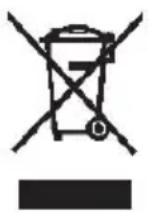
This symbol on the products, packaging, and/or accompanying documents mean that used electrical and electronic products and batteries should not be mixed with general household waste. For proper treatment, recovery and recycling of old products and used batteries, please take them to applicable collection points, in accordance with your national legislation and the Directives 2012/19/EU and 2006/66/EC.
By disposing of these products and batteries correctly, you will help to save valuable resources and prevent any potential negative effects on human health and the environment which could otherwise arise from inappropriate waste handling.
For more information about collection and recycling of old products and batteries, please contact your local municipality, your waste disposal service or the point of sale where you purchased the items.
Penalties may be applicable for incorrect disposal of this waste, in accordance with national legislation.

For business users in the European Union.
If you wish to discard electrical and electronic equipment, please contact your dealer or supplier for further information.
Information on Disposal in other Countries outside the European Union
These symbols are only valid in the European Union. If you wish to discard this product, please contact your local authorities or dealer and ask for the correct method of disposal.
Disposal
- Empty all contents.
- Defrost completely and clean the interior to prevent odor and mold.
- Remove or destroy locks to avoid risk of child entrapment.
- Remove the 2 batteries as shown in the Technical manual p. 42-45
- The battery must not be disposed of with general household waste.
- Battery and appliance is brought to applicable disposal service.
- Do not attempt to remove refrigerants or compressor oil yourself.
Replacement of connecting board

- Access electrical components Dismount 6 x Torx 20 screws and unmount the junction-box lid

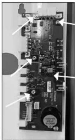
- Used Torx 20 to loosen the 6 screws

- By hand gently press the lock function on both sides of the power wires plugs and slide backwards

to the new board wire socket.

- Make sure the wire colors is one by one9. S
Keep drain clean
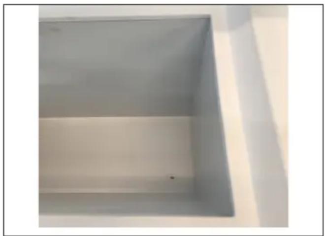
- The drain is in the bottom 2. Remove the filter if there is getting any problems with the drain.
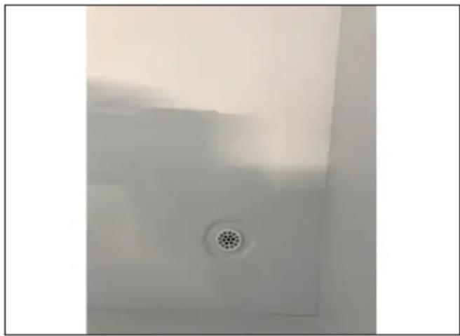
If the appliance drain becomes blocked by any objects, the water can't drain away as it should from the vacciencompartment, which will result in water accumulating, which further could result in creating issues with the stored vaccine vials, stickers, cardboard boxes, etc.
This is why it is an important SOP procedure, to regularly ensure that the drain filter is clean and free from dirt and waste.
To do the cleaning, use lukewarm water with a mild cleaning agent on a soft cloth, and wipe off the filter along with the surrounding bottom.
Finish off with a dry dishtowel or similar, to ensure all objects are removed and the bottom is dry.


- Use a very small bottle cleaner, if cleaning becomes necessary in the tube.
Compressor replacement
Procedure of compressor switch.
1: WARNING! Drain coolant R600a from refrigeration system by vacuum suction.
2: IMPORTANT! Blow refrigeration system with NO/Nitrogen
3: Cut
A: Suction and pressure tube
B: Capillary tube
C: Dry filter
4: Dismount starting device ECU
5: Dismount old compressor
6: Insert new compressor
7: Solder
A. Suction and pressure tube
B. Capillary tube
C. Dry filter
8: Install starting device ECU
IMPORTANT! When solder copper tubes to iron tubes use silver tin
Filling of new refrigerant
9: Drain refrigeration system by vacuum suction
10: Check type sticker for required amount of R600a to fill on refrigerant system
Fill 50g of R600a refrigerant on the system
- WARNING
- PERFORM THE FOLLOWING STEPS TO PREVENT ESD DAMAGE
- CONTENTS
- PERIODIC PREVENTIVE MAINTENANCE CHECKS
- DAILY CHECK
- WEEKLY MAINTENANCE
- MONTHLY MAINTENANCE
- MONTH
- YEARLY MAINTENANCE
- REGULARLY
- COMPLETE SPARE PART LIST VLS096A AC
- POSITION ITEM NUMBER ITEM NAME
- HEALTH AND SAFETY GUIDANCE – WARNING
- REQUIRED BASIC TOOLS
- VOLTAGE STABILIZERS
- LED - INDICATION
- VOLTAGE STABILIZATION
- VOLTAGE & FREQUENCY MONITORING
- SPECIFICATIONS
- SAFETY INSTRUCTIONS - INSTALLATION
- WHAT THIS CHAPTER CONTAINS
- NOTE
- INSTALLATION AND MAINTENANCE WORK
- BEFORE POWERING THE DEVICE
- FUSE TROUBLE SHOOTING
- MAINTENANCE, DIAGNOSTIC AND REPAIR PROCEDURES
- STORAGE
- END OF LIFE RESOURCE RECOVERY AND RECYCLING PROCEDURES
- GENERALE DESCRIPTION
- CONTROLLING LOADS
- COMPRESSOR
- HEATER
- REGULATION FREQUENCY
- DATALOGGER
- TIME KEEPING, STAND ALONE
- TIME KEEPING, INTERANL CONNECTION TO LEVEL
- MAX AND MIN TEMPERATURE MEMORIZATION
- HOW TO SEE THE MIN TEMPERATURE
- HOW TO SEE THE MAX TEMPERATURE
- HOW TO RESET THE MAX AND MIN TEMPERATURE RECORDED
- ALARMS
- LIST OF ALARMS AND ERROR CODES
- BATTERY MODE
- HOLD OVER TIME
- FAULT HANDLING
- SAFETY THERMOSTAT
- PRODUCTION MODE
- TURNING THE APPLIANCE ON AND OFF
- AC MODE
- SDD MODE
- TURNING THE APPLIANCE OFF
- PARAMETER MENU
- HOW TO ENTER THE PARAMETER MENU
- TECHNICAL MENU
- HOW TO ENTER THE TECHNICAL MENU
- PARAMETER
- REGULATION
- FREEZER REGULATION
- FAN CONTROL
- GB
- HOLD OVER TIME CALCULATION
- OPERATION CONDITION
- OTHER
- MOTOR COMPARTMENT
- VOLTAGE STABILIZER ECU REPLACEMENT
- TRANSFORMER REPLACEMENT
- STARTING DEVICE REPLACEMENT
- RUN CAPACITOR REPLACEMENT
- THERMOSTAT SENSOR REPLACEMENT FOR REFRIGERATOR
- THERMOSTAT SENSOR REPLACEMENT FOR FREEZER
- IMPORTANT
- HOW TO ACCESS THE ELECTRICAL BOX
- EHC- USB CHARGING PORTS REPLACEMENT
- V MONITORING POWER REPLACEMENT
- M2M - LOGGER DATA STICK REPLACEMENT
- CIRCUIT BREAKER REPLACEMENT
- POWER SUPPLY REPLACEMENT
- REPLACEMENT OF CONNECTING BOARD
- BATTERY REPLACEMENT FOR CONNECTION BOARD
- EMS DISPLAY
- BATTERY REPLACEMENT FOR EMS
- EXTERNAL ANTENNA
- COMPRESSOR REPLACEMENT
- ⚠️ IMPORTANT SAFETY NOTE
- SAFETY FIRST
- PREPARATION & SAFETY
- RECOVERY OF OLD REFRIGERANT
- SYSTEM EVACUATION
- ON-SITE CHECKLIST
- TECHNICAL SUPPORT
- CONTACT
- VESTFROST SOLUTIONS
- RECYCLING PROCEDURES/DISPOSAL
- INFORMATION FOR USERS ON COLLECTION AND DISPOSAL OLD EQUIPMENT AND USED BATTERIES
- FOR BUSINESS USERS IN THE EUROPEAN UNION
- INFORMATION ON DISPOSAL IN OTHER COUNTRIES OUTSIDE THE EUROPEAN UNION
- DISPOSAL
- KEEP DRAIN CLEAN
Brand : VESTFROST
Model : VLS 096A RF AC
Category : Refrigerator