
Matrice 4 - Drone DJI - Free user manual and instructions
Find the device manual for free Matrice 4 DJI in PDF.


| Product Type | Consumer/Professional Drone (Quadcopter) |
| Brand | DJI |
| Model | Matrice 4 |
| Dimensions (Unfolded) | About 810 × 670 × 430 mm (excluding propellers) |
| Weight | Approx. 1,400 g (without gimbal and camera) |
| Maximum Takeoff Weight | 2,000 g |
| Power Source | Rechargeable intelligent flight battery (LiPo, 6S, 5,000 mAh) |
| Flight Time | Up to 45 minutes (no payload, ideal conditions) |
| Maximum Transmission Distance | Up to 15 km (with DJI O3 transmission, unobstructed) |
| Camera System | Compatible with DJI Zenmuse payloads (e.g., X4S, X5S, thermal) |
| Gimbal Stabilization | 3-axis mechanical gimbal compatible |
| Obstacle Avoidance | Full-directional sensing (forward, backward, left, right, top, bottom) |
| GPS | Dual-frequency GPS/GLONASS/BeiDou, return-to-home functionality |
| Maximum Speed | 68 km/h (in Sport mode) |
| Wind Resistance | Level 7 (able to fly in winds up to 15 m/s) |
| Remote Controller | DJI RC Plus, 7.02-inch touchscreen, 3.3 km transmission range |
| Main Functions | Intelligent flight modes (Waypoint, TapFly, ActiveTrack, Point of Interest), automated missions |
| Maintenance and Cleaning | Clean camera lens and sensors with soft cloth; inspect propellers for damage before each flight |
| Safety Precautions | Fly in open areas away from people/crowds; keep within visual line of sight; follow local aviation regulations |
| Spare Parts and Repairability | Replaceable propellers, arms, gimbal, camera, batteries, and landing gear design |
| Included Accessories | Remote controller, intelligent flight battery, charger, 16 GB SD card, carrying case, user manual |
| Warranty | 1-year manufacturer warranty (subject to terms) |
Frequently Asked Questions - Matrice 4 DJI
User questions about Matrice 4 DJI
0 question about this device. Answer the ones you know or ask your own.
Ask a new question about this device
Download the instructions for your Drone in PDF format for free! Find your manual Matrice 4 - DJI and take your electronic device back in hand. On this page are published all the documents necessary for the use of your device. Matrice 4 by DJI.
USER MANUAL Matrice 4 DJI
This document is copyrighted by DJI with all rights reserved. Unless otherwise authorized by DJI, you are not eligible to use or allow others to use the document or any part of the document by reproducing, transferring or selling the document. Only refer to this document and the content thereof as instructions to operate DJI products. The document should not be used for other purposes.
In the event of divergence among different versions, the English version shall prevail.

Searching for Keywords
Search for keywords such as "battery" and "install" to find a topic. If you are using Adobe Acrobat Reader to read this document, press Ctrl+F on Windows or Command+F on Mac to begin a search.

Navigating to a Topic
View a complete list of topics in the table of contents. Click on a topic to navigate to that section.

Printing this Document
This document supports high resolution printing.
Using this Manual

- The operating temperature of this product is -10° to 40° C. It does not meet the standard operating temperature for military-grade application ( -55° to 125° C), which is required to endure greater environmental variability. Operate the product appropriately and only for applications that meet the operating temperature range requirements of that grade.
Legend

Important

Hints and Tips

Reference
Read Before Use
DJI TM provides you with tutorial videos and the following documents:
- Safety Guidelines
- Quick Start Guide
- User Manual
It is recommended to watch all the tutorial videos and read the Safety Guidelines before using for the first time. Make sure to review the Quick Start Guide before using for the first time and refer to this User Manual for more information.
Video Tutorials
Go to the address below or scan the QR code to watch the tutorial videos, which demonstrate how to use the product safely:
https://enterprise.dji.com/matrice-4-series/video
Download DJI Assistant 2
Download and install DJI ASSISTANT™ 2 (Enterprise Series) using the link below:
https://www.dji.com/downloads/softwares/assistant-dji-2-for-matrice
Contents
Using this Manual 3
Legend 3
Read Before Use 3
Video Tutorials 3
Download DJI Assistant 2 4
1 Overview 9
1.1 Aircraft 9
1.2 Remote Controller 10
2 Flight Safety 12
2.1 Operating the Aircraft Responsibly 12
2.2 Flight Restrictions 12
GEO (Geospatial Environment Online) System 12
GEO Zones 13
Flight Restrictions 13
Buffer Zone 15
Unlocking GEO Zones 16
Flight Altitude and Distance Limits 16
2.3 Flight Environment Requirements 17
3 Using for the First Time 19
3.1 Charging the Battery 19
3.2 Preparing the Remote Controller 19
Adjusting the Antennas 19
3.3 Preparing the Aircraft 20
3.4 Activation 20
3.5 Basic Flight 21
Pre-Flight Checklist 21
Starting/Stopping the Motors 22
Starting the Motors 22
Stopping the Motors 22
Stopping the Motors Mid-Flight 23
Controlling the Aircraft 23
4 Aircraft 25
4.1 Flight Modes 25
4.2 Aircraft Status Indicator 26
4.3 Beacon 27
4.4 Propellers 28
Notice 28
4.5 Camera 29
Storing and Exporting Photos and Videos 30
4.6 Gimbal 30
Gimbal Angle 30
Gimbal Notice 30
4.7 Intelligent Flight Battery 31
Notice 31
Inserting/Removing the Battery 32
Checking the Battery Level 33
Charging the Battery 33
Using the Charging Hub 33
Battery Level LEDs 35
Battery Protection Mechanisms 35
4.8 Aircraft RTK 35
Enabling/Disabling RTK 36
Custom Network RTK 36
4.9 Return to Home 36
Notice 37
Advanced RTH 39
Trigger Method 39
RTH Procedure 40
RTH Settings 42
Landing Protection 44
4.10 Sensing System 45
Notice 46
Vision Assist 47
4.11 Advanced Pilot Assistance Systems 48
Notice 49
Landing Protection 49
4.12 DJI AirSense 49
4.13 Expansion Port 51
5 Remote Controller 52
5.1 Charging the Battery 52
5.4 Operating the Touchscreen 53
5.5 Remote Controller LEDs 54
Status LED 54
Battery Level LEDs 55
5.6 Remote Controller Alert 55
5.7 Optimal Transmission Zone 56
5.8 Linking the Remote Controller 56
5.9 HDMI Settings 57
6 DJI Pilot 2 App 58
6.1 Homepage 58
6.2 Camera View 59
Top Bar 59
Navigation Display 60
Zoom Camera View 62
Wide-Angle Camera View 64
Thermal Camera View 64
Laser Rangefinding 66
Primary Flight Display 66
7 Flight Operations 69
7.1 Annotation Management and Synchronization 69
PinPoint 69
Line and Area Annotation Management 70
Annotation Sharing 71
7.2 Intelligent functions 71
POI 71
7.3 Flight Tasks 72
Waypoint Route 73
Set Waypoints 74
Live Mission Recording 75
Area Route 76
Smart Oblique 77
Terrain follow 77
Linear Route 79
Set Waypoints 80
Live Mission Recording 80
Slope Route 80
Create Slope 80
Adjust and Confirm AR Slope 81
Adjust Flight Route Parameters 82
Geometric Route 82
Set the Bottom Base Shape 82
Set Altitude 83
Adjust Flight Route Parameters 84
Smart 3D Capture 84
Collecting Aerial Photogrammetry Data 85
Route Parameters 86
Data Storage 90
Photo File 90
Image Log File 93
GNSS Observation File 93
8 Appendix 94
8.1 Specifications 94
8.2 Firmware Update 94
Using DJI Pilot 2 94
Aircraft and Remote Controller Firmware Update 94
Offline Firmware Update 94
Using DJI Assistant 2 (Enterprise Series) 94
Aircraft and Remote Controller Firmware Update 94
Notices 95
8.3 Flight Data 95
8.4 Using Enhanced Transmission 96
Inserting the nano-SIM Card 96
Installing the DJI Cellular Dongle 2 97
Using Enhanced Transmission 98
Security Strategy 98
Remote Controller Usage Notes 98
4G Network Requirements 99
8.5 Post-Flight Checklist 99
8.6 Maintenance Instructions 100
8.7 Troubleshooting Procedures 101
8.8 Risks and Warnings 101
8.9 Disposal 102
8.10 C2 Certification 102
Remote Controller Warnings 104
Direct Remote ID 104
GEO Awareness 104
GEO Zones 105
EASA Notice 107
Original Instructions 108
8.11 FAR Remote ID Compliance Information 108
1 Overview
1.1 Aircraft
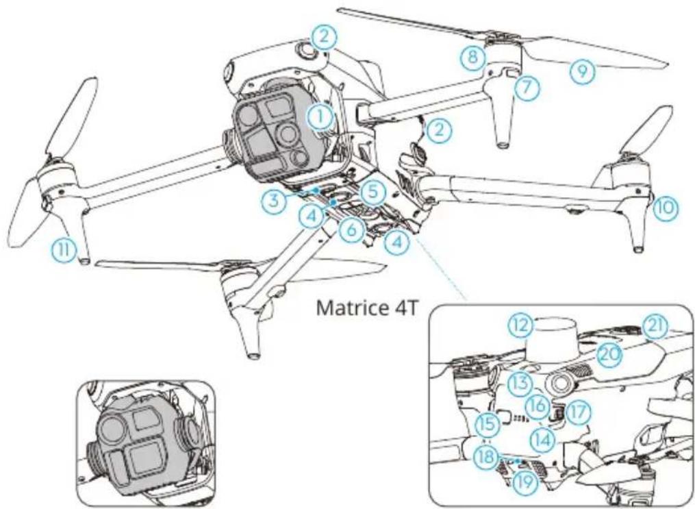
Matrice 4E
- Gimbal and Camera
- Omnidirectional Vision System
- Expansion Port
- Downward Vision System
- Three-Dimensional Infrared Sensing System
- Auxiliary Light
- Front LEDs
- Motors
- Propellers
-
Aircraft Status Indicators
-
Landing Gears (built-in antennas)
- GNSS Antenna
- Beacon
- Intelligent Flight Battery
- Power Button
- Battery Level LEDs
- Battery Buckles
- USB-C Assistant Port (E-Port Lite)
- microSD Card Slot
- Cellular Dongle Compartment
- E-Port
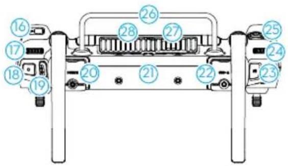
1.2 Remote Controller
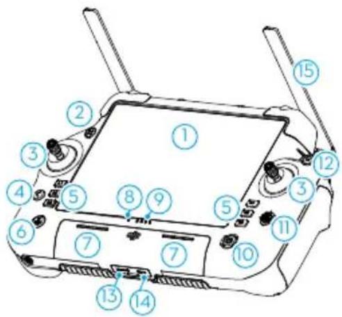
- Touchscreen
- Connection Status LED
- Joystick
- Back/Function Button
Press once to return to the previous screen. Press twice to return to the home screen.
Use the back button and another button to activate combination buttons. Refer to the Button Combinations section for more information.
- L1/L2/L3/R1/R2/R3 Buttons
Go to camera view in DJI Pilot 2 to view the specific functions of these buttons.
- Return to Home (RTH) Button
Press and hold to initiate RTH. Press again to cancel RTH.
- Microphone
- Status Indicator
- Battery Level LEDs
- Power Button
Press once to check the current battery level. Press once, then press
again and hold to power the remote controller on or off. While the remote controller is powered on, press once to turn the touchscreen on or off.
- 5D Button
- Flight Pause Button
Press once to make the aircraft brake and hover in place (only when GNSS or Vision Systems are available).
- microSD Card Slot
- USB-C Port
- External Antennas
- Customizable C3 Button
- Gimbal Dial
- Record Button
- Flight Mode Switch
- HDMI Port
- Internal Antennas
- USB-A Port
Users can insert third-party devices, such as a USB flash drive or a memory card.
- Focus/Shutter Button
Press the button halfway down for autofocus and all the way down to take a photo.
-
Camera Zoom Dial
-
Customizable C4 Scroll Wheel
-
Handle
-
Speaker
-
Air Vent
-
Reserved Mounting Holes
-
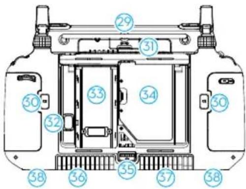
Customizable C1/C2 Buttons
-
Rear Cover
-
Battery Release Button
-
Battery Compartment
For installing the WB37 intelligent battery.
-
Cellular Dongle Compartment
-
Rear Cover Release Button
-
Alarm
-
Air Intake
-
M4 Screw Holes
2 Flight Safety
After completing pre-flight preparations, it is recommended to train your flying skills and practice flying safely. Pick a suitable area to fly in according to the following flight requirements and restrictions. Strictly abide by local laws and regulations when flying. Read the Safety Guidelines before flight to ensure safe use of the product.
2.1 Operating the Aircraft Responsibly
To avoid serious injury and property damage, observe the following rules:
- Make sure you are NOT under the influence of anesthesia, alcohol, or drugs or suffering from dizziness, fatigue, nausea, or other conditions that could impair the ability to operate the aircraft safely.
- After landing, power off the aircraft first, then switch off the remote controller.
- DO NOT drop, launch, fire, or otherwise project any dangerous payloads on or at any buildings, persons, or animals, which could cause personal injury or property damage.
- DO NOT use an aircraft that has been accidentally damaged, crashed, or is not in good condition.
- Make sure to train sufficiently and have contingency plans for emergencies or if an incident occurs.
- Make sure to have a flight plan. DO NOT fly the aircraft recklessly.
- Respect the privacy of others when using the camera. Make sure to comply with local privacy laws, regulations, and moral standards.
- DO NOT use this product for any reason other than general personal use.
- DO NOT use it for illegal or inappropriate purposes such as spying, military operations, or unauthorized investigations.
- DO NOT use this product to defame, abuse, harass, stalk, threaten, or otherwise violate legal rights such as the right to privacy and publicity of others.
- DO NOT trespass onto the private property of others.
2.2 Flight Restrictions
GEO (Geospatial Environment Online) System
The DJI Geospatial Environment Online (GEO) System is a global information system that provides real-time information on flight safety and restriction updates and prevents
UAVs from flying in restricted airspace. Under exceptional circumstances, restricted areas can be unlocked to allow flights. Prior to that, you must submit an unlocking request based on the current restriction level in the intended flight area. The GEO system may not fully align with local laws and regulations. You are responsible for your own flight safety and must consult with the local authorities on the relevant legal and regulatory requirements before requesting to unlock a restricted area. For more information about the GEO system, visit https://fly-safe.dji.com.
GEO Zones
The DJI GEO system designates safe flight locations, provides risk levels and safety notices for individual flights, and offers information on restricted airspace. All restricted flight areas are referred to as GEO Zones, which are further divided into Restricted Zones, Authorization Zones, Warning Zones, Enhanced Warning Zones, and Altitude Zones. You can view such information in real-time in DJI Pilot 2. GEO Zones are specific flight areas, including but not limited to airports, large event venues, locations where public emergencies have occurred (such as forest fires), nuclear power plants, prisons, government properties, and military facilities. By default, the GEO system limits takeoffs and flights in zones that may cause safety or security concerns. A GEO Zone map that contains comprehensive information on GEO Zones around the globe is available on the official DJI website: https://fly-safe.dji.com/nfz/nfz-query.
Flight Restrictions
The following section describes in detail the flight restrictions for the above mentioned GEO Zones.
Restricted Zones (Red)
UAVs are prohibited from flying in Restricted Zones. If you have obtained permission to fly in a Restricted Zone, visit https://fly-safe.dji.com or contact flysafe@dji.com to unlock the zone.
Scenario
Takeoff: the aircraft motors cannot be started in Restricted Zones.
In Flight: when the aircraft flies inside a Restricted Zone, a 100-second countdown will commence in DJI Pilot 2. When the countdown is finished, the aircraft will land immediately in semi-automatic descent mode and turn off its motors after landing.
In Flight: when the aircraft approaches the boundary of a Restricted Zone, the aircraft will automatically decelerate and hover.
Authorization Zones (Blue)
The aircraft will not be able to take off in an Authorization Zone unless it obtains a permission to fly in the area.
Scenario
Takeoff: the aircraft motors cannot be started in Authorization Zones. To fly in an Authorization Zone, the user is required to submit an unlocking request registered with a DJI-verified phone number.
In Flight: when the aircraft flies inside an Authorization Zone, a 100-second countdown will commence in DJI Pilot 2. When the countdown is finished, the aircraft will land immediately in semi-automatic descent mode and turn off its motors after landing.
Warning Zones (Yellow)
A warning will be displayed when the aircraft flies inside a Warning Zone.
Scenario
The aircraft can fly in the zone but the user is required to understand the warning.
Enhanced Warning Zones (Orange)
When the aircraft flies in an Enhanced Warning Zone, a warning will be displayed prompting the user to confirm the flight path.
Scenario
The aircraft can continue to fly once the warning is confirmed.
Altitude Zones (Gray)
The aircraft altitude is limited when flying inside an Altitude Zone.
Scenario
When the GNSS signal is strong, the aircraft cannot fly above the altitude limit.
In Flight: when the GNSS signal changes from weak to strong, a 100-second countdown will commence in DJI Pilot 2 if the aircraft exceeds the altitude limit. When the countdown is finished, the aircraft will descend below the altitude limit and hover.
When the aircraft approaches the boundary of an Altitude Zone and the GNSS signal is strong, the aircraft will decelerate automatically and hover if the aircraft is above the altitude limit.

- Semi-Automatic Descent: all stick commands except the throttle stick command and the RTH button are available during descent and landing. The aircraft motors will turn off automatically after landing. It is recommended to fly the aircraft to a safe location before the semi-automatic descent.
Buffer Zone
Buffer Zones for Restricted Zones/Authorization Zones
To prevent the aircraft from accidentally flying into a Restricted or Authorization Zone, the GEO system creates a buffer zone of about 20 meters wide outside each Restricted and Authorization Zone. As shown in the illustration below, the aircraft can only take off and land in place or fly toward an opposite direction of the Restricted or Authorization Zone when inside the buffer zone, and cannot fly toward the Restricted or Authorization Zone unless an unlocking request has been approved. The aircraft cannot fly back into the buffer zone after leaving the buffer zone.
Buffer Zones for Altitude Zones
A buffer zone of about 20 meters wide is established outside each Altitude Zone. As shown in the illustration below, when approaching the buffer zone of an Altitude Zone in a horizontal direction, the aircraft will gradually reduce its flight speed and hover outside the buffer zone. When approaching the buffer zone from underneath in a vertical direction, the aircraft can ascend and descend in altitude or fly in an opposite direction of the Altitude Zone, but cannot fly toward the Altitude Zone. The aircraft cannot fly back into the buffer zone in a horizontal direction after leaving the buffer zone.
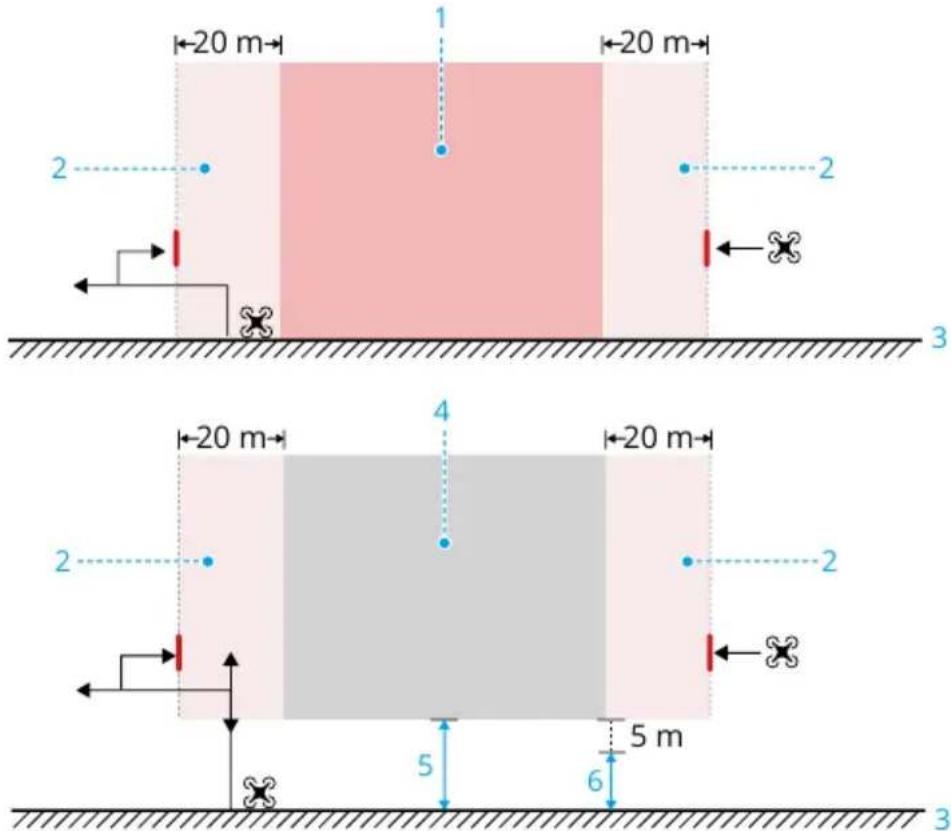
-
Restricted Zone/Authorized Zone
-
Buffer Zone
-
Ground
-
Altitude Zone
-
Altitude Limit
-
Flight Altitude
Unlocking GEO Zones
Self-Unlocking is intended for unlocking Authorization Zones. To complete Self-Unlocking, you must submit an unlocking request via the DJI FlySafe website at https://fly-safe.dji.com. Once the unlocking request is approved, you can synchronize the unlocking license through the DJI Pilot 2 app. To unlock the zone, alternatively, you can launch or fly the aircraft directly into the approved Authorization Zone and follow the prompts in DJI Pilot 2 to unlock the zone.
Custom Unlocking is tailored for users with special requirements. It designates user-defined custom flight areas and provides flight permission documents specific to the needs of different users. This unlocking option is available in all countries and regions and can be requested via the DJI FlySafe website at https://fly-safe.dji.com.
Unlocking on Mobile Device: Run the DJI Pilot 2 app and tap GEO Zone Map on the home screen. View the list of the unlocking licenses and tap ⓘ to view details of the unlocking license. A link to the unlocking license and a QR code will be displayed. Use your mobile device to scan the QR code and apply to unlock directly from the mobile device.

- To ensure flight safety, the aircraft will not be able to fly out of the unlocked zone after entering it. If the Home Point is outside the unlocked zone, the aircraft will not be able to return home.
Flight Altitude and Distance Limits
Max altitude restricts the flight altitude of the aircraft, while max distance restricts the flight radius around the Home Point of the aircraft. These limits can be changed in the DJI Pilot 2 app for improved flight safety.
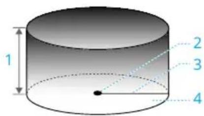
-
Max Altitude
-
Home Point (Horizontal Position)
-
Max Distance
-
Height of aircraft when taking off
Strong GNSS Signal
| Flight Restrictions Prompt in DJI Pilot 2 App | ||
| Max Altitude | Altitude of the aircraft cannot exceed the value set in DJI Pilot 2. | Max flight altitude reached. |
| Max Distance | The straight-line distance from the aircraft to the Home Point cannot exceed the max flight distance set in DJI Pilot 2. | Max flight distance reached. |
Weak GNSS Signal
| Flight Restrictions Prompt in DJI Pilot 2 App | ||
| Max Altitude | • Altitude is restricted to 60 m from the takeoff point if lighting is sufficient.• Altitude is restricted to 3 m above the ground if lighting is not sufficient and the 3D infrared sensing system is functioning.• Altitude is restricted to 60 m from the takeoff point if lighting is not sufficient and the 3D infrared sensing system is not functioning. | Max flight altitude reached. |
| Max Distance No | limit | |

• Each time the aircraft is powered on, the altitude limit will be automatically removed as long as the GNSS signal becomes strong (GNSS signal strength ≥ 2), and the limit will not take effect even if the GNSS signal becomes weak afterwards.
- If the aircraft flies out of the set flight range due to inertia, you can still control the aircraft but cannot fly it any further away.
2.3 Flight Environment Requirements
- DO NOT fly in severe weather conditions such as strong winds, snow, rain, and fog.
- Only fly in open areas. Tall buildings and large metal structures may affect the accuracy of the onboard compass and GNSS system. After takeoff, make sure you are notified with the voice prompt that the Home Point is updated before continuing flight. If the aircraft has taken off near buildings, the accuracy of the Home Point cannot be guaranteed. In this case, pay close attention to the current position of
the aircraft during auto RTH. When the aircraft is close to the Home Point, it is recommended to cancel auto RTH and manually control the aircraft to land at an appropriate location.
- Fly the aircraft within visual line of sight (VLOS). Avoid mountains and trees blocking GNSS signals. Any flight beyond visual line of sight (BVLOS) can be conducted only when the aircraft performance, the knowledge and skills of the pilot, and the operational safety management are compliant with local regulations for BVLOS. Avoid obstacles, crowds, trees, and bodies of water. For safety reasons, DO NOT fly the aircraft near airports, highways, railway stations, railway lines, city centers, or other sensitive areas, unless any permit or approval is obtained under local regulations.
- Make sure the beacon and the auxiliary bottom light are enabled at night for flight safety.
- The performance of the aircraft and its battery is limited when flying at high altitudes. Fly with caution. DO NOT fly above the specified altitude.
- The braking distance of the aircraft is affected by the flight altitude. The higher the altitude, the greater the braking distance. When flying at high altitudes, you should reserve adequate braking distance to ensure flight safety.
- GNSS cannot be used on the aircraft in polar regions. Use the vision system instead.
- DO NOT take off from moving objects such as cars, ships, and airplanes.
- DO NOT take off from solid-colored surfaces or surfaces with strong reflections such as a car roof.
- Be careful when taking off in the desert or from a beach to avoid sand entering the aircraft.
- DO NOT operate the aircraft near bird flocks.
3 Using for the First Time
Click the link or scan the QR code to watch the tutorial videos.
https://enterprise.dji.com/matrice-4-series/video
3.1 Charging the Battery
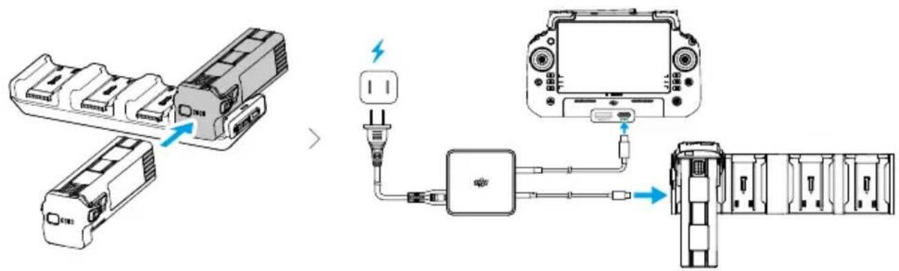

- Charge the remote controller to activate the internal battery before using for the first time.
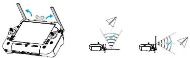
3.2 Preparing the Remote Controller
Adjusting the Antennas
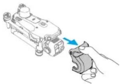
3.3 Preparing the Aircraft
- Remove the gimbal protector from the camera.
- Unfold the front arms.
- Unfold the rear arms.
- Install the Intelligent Flight Battery.
- Match the propellers to motors. Press the propellers down and rotate until they click in place.
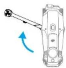
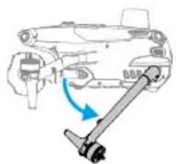
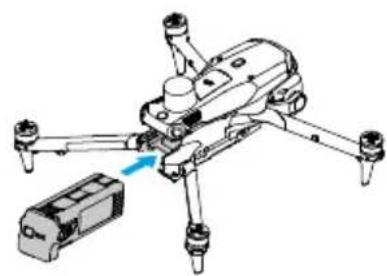
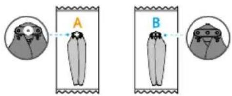
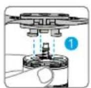
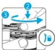
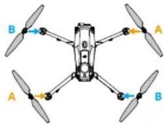
3.4 Activation
The aircraft and remote controller require activation before using for the first time. Press, and then press again and hold the power button to power on the devices. Follow the
on-screen prompts to activate. Ensure that the remote controller can access the internet during activation.
3.5 Basic Flight
Pre-Flight Checklist
- Make sure the remote controller and the aircraft batteries are fully charged, and that both of the battery buckles pop out ensuring that the Intelligent Flight Battery is installed firmly.
- Make sure there are no foreign objects inside the aircraft or its components, such as water, oil, soil, or sand. Make sure the air vents of the aircraft, the cooling holes of the camera, and the ventilation holes of the motor are not blocked. Ports such as the E-Port must be closed firmly if not used.
- Make sure the propellers are of the same model and securely mounted. Make sure the motors or propellers are not damaged or deformed, there are no foreign objects in or on the motors or propellers, and the propeller blades and arms are unfolded.
- Make sure the lenses of the vision systems, the cameras, the glass of the infrared sensors, and the auxiliary lights are clean, free of stickers, and not blocked in any way.
- Make sure to remove the gimbal protector before powering on the aircraft.
- Make sure the remote controller antennas are adjusted to the proper position.
- Make sure the firmware of all devices and DJI Pilot 2 have been updated to the latest versions.
- Power on the aircraft and the remote controller, and toggle the flight mode switch to N-mode. Make sure the status LED on the remote controller and the battery level indicators on the aircraft are solid green. This indicates that the aircraft and the remote controller are linked, and the remote controller is in control of the aircraft.
- Make sure your flight area is inside approved zones for UAVs, and flight conditions are suitable for flying the aircraft. Place the aircraft on open and flat ground. Make sure there are no obstacles, buildings, or trees nearby and that the aircraft is 5 m away from the pilot. The pilot should be facing the rear of the aircraft.
- To ensure flight safety, enter the flight view of DJI Pilot 2 and check the parameters on the preflight checklist.
-
Make sure DJI Pilot 2 is properly opened to assist your operation of the aircraft. WITHOUT THE FLIGHT DATA RECORDED BY THE DJI Pilot 2 APP, IN CERTAIN SITUATIONS (INCLUDING THE LOSS OF YOUR AIRCRAFT), DJI MAY NOT BE ABLE TO PROVIDE AFTER SALES SUPPORT TO YOU OR ASSUME LIABILITY.
-
Divide the airspace for flight when multiple aircrafts are operating simultaneously in order to avoid collision mid-air.
Starting/Stopping the Motors
Starting the Motors
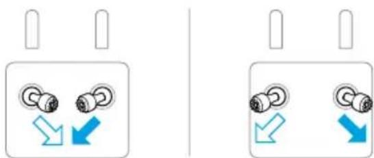
Perform one of the Combination Stick Commands (CSC) as shown below to start the motors. Once the motors have started spinning, release both sticks simultaneously.
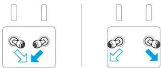
Stopping the Motors
The motors can be stopped in two ways:
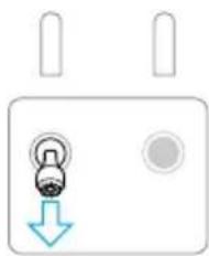
Method 1: When the aircraft has landed, push the throttle stick down and hold until the motors stop.
Method 2: When the aircraft has landed, perform one of the CSC as shown below until the motors stop.
Stopping the Motors Mid-Flight

- Stopping the motors mid-flight will cause the aircraft to crash.
The Combination Stick Command (CSC) can be used to stop the motors once the flight controller detects critical error during flight.
Controlling the Aircraft
The control sticks of the remote controller can be used to control the aircraft movements. The control sticks can be operated in Mode 1, Mode 2, or Mode 3, as shown below.
The default control mode of the remote controller is Mode 2. In this manual, Mode 2 is used as an example to illustrate how to use the control sticks. The more the stick is pushed away from the center, the faster the aircraft moves.
Mode 1
![graph TD A["Device Setup 1"] -->|Blue Arrow Down| B["Paper airplane Left"] A -->|Orange Arrow Up| C["Paper airplane Right"] D["Device Setup 2"] -->|Blue Arrow Down| E["Paper airplane Left"] D -->|Orange Arrow Up| F["Paper airplane Right"] G["Device Setup 3"] -->|Blue Arrow Down| H["Paper airplane Le…](/content/2026/08/1627030/images/2c88f7d4cbc02136db3661b24282827ad121d0bf0d9b75d068e6f31456d99b3e.jpg)
Mode 2
![graph TD A["Device Setup 1"] -->|Blue Up/Down Arrow| B["Paper airplane"] C["Device Setup 2"] -->|Blue Up/Down Arrow| D["Paper airplane"] E["Device Setup 3"] -->|Blue Up/Down Arrow| F["Paper airplane"] G["Device Setup 4"] -->|Blue Up/Down Arrow| H["Paper airplane"] I["Device Setup 5"] -->|Blue Up/Dow…](/content/2026/08/1627030/images/facca70aff7a746671d5223ee93aff6a866123d0684f31a114273aa0e0c0e863.jpg)
Mode 3
![graph TD A["Device Setup 1"] -->|Blue Arrow Down| B["Paper airplane"] A -->|Orange Arrow Up| C["Paper airplane"] D["Device Setup 2"] -->|Blue Arrow Down| E["Paper airplane"] D -->|Orange Arrow Up| F["Paper airplane"] G["Device Setup 3"] -->|Blue Arrow Down| H["Paper airplane"] G -->|Orange Arrow Up|…](/content/2026/08/1627030/images/4eeeda29210cc42a6dd67c2fdc4f5d87d61b8ec624c2a4f230b8646d4c04e342.jpg)
4 Aircraft
4.1 Flight Modes
The aircraft supports the following flight modes, which can be switched via the Flight Mode switch on the remote controller.
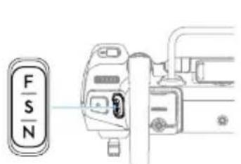
| Position Flight Mode |
| F Function mode |
| S Sport mode |
| N Normal mode |
Normal Mode
Normal Mode is suitable for most flight scenarios. The aircraft can hover precisely, fly stably, and use Intelligent Flight Modes. If obstacle sensing is enabled, obstacles can also be avoided using the vision system.
Sport Mode
The maximum horizontal flight speed of the aircraft will be higher when compared with Normal mode. Note that obstacle sensing is disabled in Sport Mode.
Function Mode
Function mode can be set to T-mode (Tripod mode) or A-mode (Attitude mode) in DJI Pilot 2. T-mode is based on Normal mode. The flight speed is limited to allow easier control of the aircraft. Attitude mode must be used with caution.
The aircraft automatically changes to Attitude (ATTI) mode when the vision systems are unavailable or disabled and the GNSS signal is weak or the compass experiences interference. In ATTI mode, the aircraft may be more easily affected by its surroundings. Environmental factors such as wind can result in horizontal drift of the aircraft, which may present hazards, especially when flying in confined spaces. The aircraft will not be able to hover or brake automatically, therefore the pilot should land the aircraft as soon as possible to avoid accidents.
If the aircraft is flying in the EU, the aircraft will switch to Low Speed mode when the flight mode is switched to F (T-mode) on the remote controller. Low Speed mode limits the maximum horizontal flight speed to 2.8 m / s based on Normal mode, and there is no limit for the ascent or descent speed.

• DO NOT switch from Normal mode to other modes unless you are sufficiently familiar with the aircraft behavior under each flight mode. You must turn on
Multiple Flight Modes in DJI Pilot 2 before switching from Normal mode to other modes.

- The vision systems are disabled in Sport mode, which means the aircraft cannot sense obstacles on its route automatically. The user must stay alert to the surrounding environment and control the aircraft to avoid obstacles.
- The maximum flight speed and braking distance of the aircraft significantly increases in Sport mode. When flying in windless conditions, make sure to maintain enough braking distance to ensure flight safety.
- When the aircraft is ascending or descending in Sport mode or Normal mode in windless conditions, make sure to maintain enough vertical braking distance to ensure flight safety.
- The responsiveness of the aircraft significantly increases in Sport mode, which means a small control stick movement on the remote control device translates into the aircraft moving a large distance. Make sure to maintain adequate maneuvering space during flight.
4.2 Aircraft Status Indicator
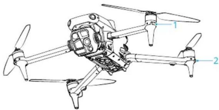
1. Front LED 2. Aircraft Status Indicator
When the aircraft is powered on but the motors are not running, the front LEDs glow solid red to display the orientation of the aircraft.
When the aircraft is powered on, but the motors are not running, the aircraft status indicators will display the current status of the aircraft.
Aircraft Status Indicators Descriptions
Normal States
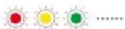
Blinks red, yellow, and green alternately
Powering on and performing self-diagnostic tests
| [0H04] × 4 ...... | Blinks yellow four times Warming up | |
| [T27K] ...... | Blinks green slowly GNSS enabled | |
 × 2 ...... × 2 ...... | Blinks green twice repeatedly | Vision systems enabled |
| [X×CZ] ...... | Blinks yellow slowly | GNSS and vision system disabled (ATTI mode enabled) |
| Warning States | ||
| Blinks yellow quickly Remote controller signal lost | ||
| Blinks red slowly Takeoff is disabled (e.g., low battery) | [1] | |
| Blinks red quickly Critically low battery | ||
| Solid red Critical error | ||
| Blinks red and yellow alternately | Compass calibration required | |
Warning States
| ...... | Blinks yellow quickly Remote controller signal lost | |
| ...... | Blinks red slowly Takeoff is disabled (e.g., low battery) | [1] |
| ...... | Blinks red quickly Critically low battery | |
| — | Solid red Critical error | |
| ...... | Blinks red and yellow alternately | Compass calibration required |
[1] If the aircraft cannot take off while the status indicators are blinking red slowly, view the warning prompt in DJI Pilot 2.
After the motors start, the front LEDs blink red and green alternately, and the aircraft status indicators blink green.

- Lighting requirements vary depending on the region. Observe local laws and regulations.
- To obtain better footage, the front LEDs turn off automatically when taking photos and videos if the front LEDs are set to Auto in DJI Pilot 2.
4.3 Beacon
The beacon on the aircraft enable you to find the aircraft when flying at night. The beacon can be manually turned on or off in DJI Pilot 2.
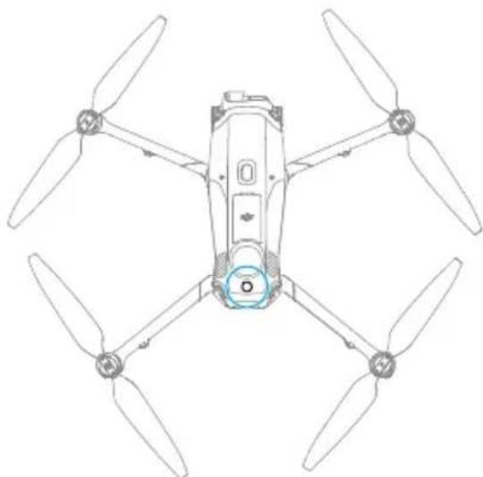

- DO NOT look directly at the beacons when they are in use to avoid damaging your eyes.
4.4 Propellers
The aircraft uses the standard propellers by default [1]. Use the low-noise propellers to reduce the noise or to comply with EU regulatory requirements.
[1] The aircraft uses low-noise propellers in EU region by default.
Notice

- The propeller blades are sharp. Handle with care to avoid personal injury or propeller deformation.
- Make sure that the propellers and motors are installed securely before each flight.
- Only use official DJI propellers. DO NOT mix propeller types.
- Propellers are consumable components. Purchase additional propellers if necessary.
- Make sure that all propellers are in good condition before each flight. DO NOT use aged, chipped, or broken propellers. Clean the propellers with a soft, dry cloth if there is any foreign matter attached.
• To avoid injury, stay away from rotating propellers or motors.
• To avoid damaging the propellers, place the aircraft correctly during transportation or storage. DO NOT squeeze or bend the propellers. If propellers are damaged, the flight performance may be affected.
- Make sure the motors are mounted securely and rotating smoothly. Land the aircraft immediately if a motor is stuck and unable to rotate freely.
- DO NOT attempt to modify the structure of the motors.
- DO NOT touch or let hands or body parts come in contact with the motors after flight, as they may be hot.
- DO NOT block any of the ventilation holes on the motors or the body of the aircraft.
• Make sure the ESCs sound normal when powered on.
4.5 Camera
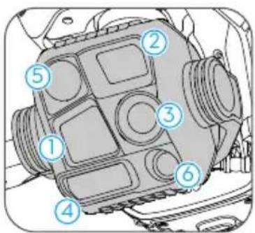
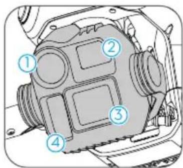
DJI Matrice 4T DJI Matrice 4E
-
Tele camera
-
Medium Tele Camera
-
Wide-Angle Camera
-
Laser Range Finder
-
Infrared Thermal Camera
-
NIR Auxiliary Light

- Due to the characteristics of the infrared sensor, the infrared sensor may become burnt before sunburn protection is triggered. DO NOT expose the infrared camera lenses to strong sources of energy such as the sun, lava, or a laser beam. Otherwise, the camera sensor may become burnt leading to permanent damage.
- Make sure the temperature and humidity are suitable for the camera during use and storage.
- Use a lens cleaner to clean the lens to avoid damage or poor image quality.
- DO NOT block any ventilation holes on the camera as the heat generated may damage the device or cause injury.
Storing and Exporting Photos and Videos
The aircraft supports the use of a microSD card to store photos and videos. Refer to the Specifications for more information about recommended microSD cards.
Remove the microSD card from the aircraft and insert it into a card reader, and export the footage in the microSD card through the card reader.

- Ensure that the SD card slot and the microSD card are clean and free of foreign objects during use.
- DO NOT remove the microSD card from the aircraft when taking photos or videos. Otherwise, the microSD card may be damaged.
- Check camera settings before use to ensure they are configured correctly.
- Before shooting important photos or videos, shoot a few images to test whether the camera is operating correctly.
- Make sure to power off the device correctly. Otherwise, the camera parameters will not be saved, and any recorded videos may be affected. DJI is not responsible for any loss caused by an image or video recorded in a way that is not machine-readable.
- Photos and videos cannot be transmitted or copied from the camera if the aircraft is powered off.
4.6 Gimbal
Gimbal Angle
Use the gimbal dial on the remote controller to control the tilt of the camera.
Alternatively, enter the camera view in DJI Pilot 2. Press the screen until a circle appears and drag the circle up and down to control the tilt of the camera.
Gimbal Notice

- Make sure the frame arms are completely unfolded before powering on. Otherwise, the gimbal rotation may be obstructed and malfunction may occur.
- Make sure there are no stickers or objects on the gimbal before taking off. DO NOT tap or knock the gimbal after the aircraft is powered on. Take off the aircraft from open and flat ground to protect the gimbal.
-
Avoid getting dust or sand on the gimbal, especially in the gimbal motors.
-
DO NOT add any extra payload other than an official accessory to the gimbal, as this may cause the gimbal to function abnormally or even lead to permanent motor damage.
- Precision elements in the gimbal may be damaged by a collision or impact, which may cause the gimbal to function abnormally. Make sure to protect the gimbal from damage.
- A gimbal motor may enter protection mode if the gimbal is obstructed by other objects when the aircraft is put on uneven ground or on grass, or if the gimbal experiences an excessive external force, such as during a collision.
- Remove the gimbal protector before powering on the device. Attach the gimbal protector when the device is not in use.
- Flying in heavy fog or clouds may make the gimbal wet, leading to temporary failure. The gimbal will recover full functionality once it is dry.
4.7 Intelligent Flight Battery
Notice

- Refer to the Safety Guidelines and the stickers on the battery before use. Users shall take full responsibility for all operation and usage.
- DO NOT charge an Intelligent Flight Battery immediately after flight as it may be too hot. Wait for the battery to cool down to the allowable charging temperature before charging again.
-
To prevent damage, the battery only charges when the battery temperature is within the allowable charging temperature. The ideal charging temperature is from 22° to 28° C ( 71.6° to 82.4° F). Charging at the ideal temperature range can prolong battery life. Charging stops automatically if the temperature of the battery cells exceed 55° C ( 131° F) during charging.
-
Low Temperature Notice:
-
Batteries cannot be used in extremely low-temperature environments of lower than -10° C ( 14° F).
- Battery capacity is significantly reduced when flying in low-temperature environments. Hover the aircraft in place for a while to warm up the battery after takeoff.
- In low-temperature environments, it is recommended to warm up the battery to room temperature before take off and keep the battery warm before use
to reduce the warm-up time. In extremely cold weather, insulate the battery as required.
- The reduced battery capacity in low-temperature environments reduces the wind speed resistance performance of the aircraft. Fly with caution.
• Take extra caution when flying at a high elevation with a low temperature.
- When the aircraft is in flight after the above conditions are satisfied, and the DJI Pilot 2 app shows a critically low battery level warning, the user is advised to stop flying immediately and land the aircraft in an appropriate place. During auto landing, users can still use the remote controller to control the aircraft's orientation. For example, users can push the throttle stick to lift the aircraft.
-
A fully charged battery will automatically discharge when it is idle for a period of time. Note that it is normal for the battery to emit heat during the discharging process.
-
Fully charge the battery at least once every three months to maintain battery health. If the battery is not used for an extended period, battery performance may be affected or may even cause permanent battery damage. If a battery has not been charged or discharged for three months or more, the battery will no longer be covered by the warranty.
-
For safety purposes, keep the batteries at a low power level in transit. Before transportation, it is recommended to discharge the batteries to 30% or lower.
-
Over-discharge protection is enabled and discharging stops automatically to prevent over-discharge when the aircraft is idle. Charge the battery to wake it from over-discharge protection before using again. Over-discharge protection is not enabled during flight.
-
Over-discharging will lead to serious damage of the battery. If the battery level is less than 10% while the aircraft is idle, the battery enters Hibernation mode to prevent over-discharge.
Inserting/Removing the Battery
Insert the Intelligent Flight Battery into the battery compartment of the aircraft. Make sure the battery is fully inserted with a clicking sound, which indicates the battery buckles are securely fastened.
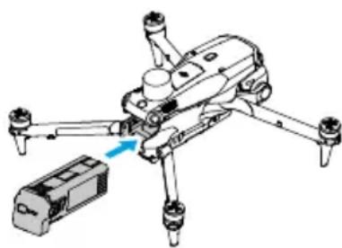
Press the battery buckle to remove the battery from the compartment.

- DO NOT insert or remove the battery while the aircraft is powered on.
- Ensure the battery is inserted with a clicking sound. DO NOT launch the aircraft when the battery is not securely mounted, as this may cause poor contact between the battery and the aircraft and present hazards. Make sure the battery is mounted securely.
Checking the Battery Level
Press the power button once to check the current battery level.
The battery level LEDs display the power level of the battery during charging and discharging. The statuses of the LEDs are defined below:
LED is on
LED is flashing
LED is off
| Blinking Pattern Battery Level | |
| 92-100% | |
| 76-91% | |
| 63-75% | |
| 51-62% | |
| 38-50% | |
| 26-37% | |
| 13-25% | |
| 0-12% |
Charging the Battery
Using the Charging Hub
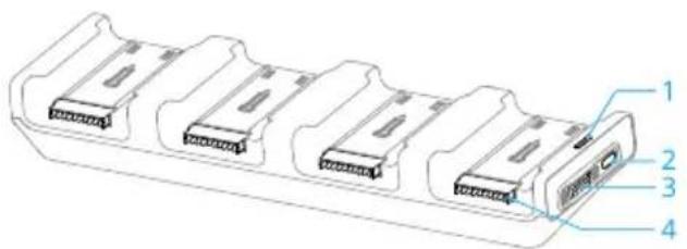
-
Status LED
-
Mode Switch
-
Power Port
-
Battery Port
Usage
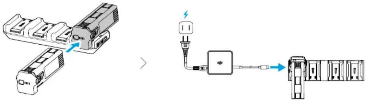
Toggle the mode switch to select a charging mode.

Standard Mode: Each battery is charged to 100% in sequence.

Ready-to-Fly Mode: Each battery is charged to 90% in sequence and kept at 90% after charging. This mode facilitates quick use of batteries.
The Intelligent Flight Battery with the highest power level will be charged first, and then the rest will be charged in sequence according to their power levels.
Disconnect the Intelligent Flight Battery from the charging hub when charging is complete.
Status LED Descriptions
| Blinking Pattern Description | |
| Solid yellow No battery is inserted | |
| Pulses green Charging the battery | |
| Solid green Charging completed | |
| Blinks yellow Recoverable abnormality of battery or charging hub (no further operation needed, charging can continue after battery or charging hub automatically recovers) | |
| Solid red Unrecoverable abnormality of battery or charging hub (remove and reinsert the battery or unplug and plug in the adapter) |

- The DJI 100W USB-C Power Adapter is required when using the charging hub to charge Intelligent Flight Batteries.
- The charging hub is only compatible with specific model of the Intelligent Flight Battery. DO NOT use the charging hub with other battery models.
- Place the charging hub on a flat and stable surface when in use. Make sure the device is properly insulated to prevent fire hazards.
- DO NOT touch the metal terminals on the battery ports. Clean the metal terminals with a clean, dry cloth if there is any noticeable buildup.
Battery Level LEDs
The table below shows the battery level during charging.
| Blinking Pattern Battery Level | |
| 0-50% | |
| 51-75% | |
| 76-99% | |
| 100% |
Battery Protection Mechanisms
The battery level LEDs can display battery protection notifications triggered by abnormal charging conditions.
| LEDs Blinking Pattern Status | ||
| LED2 blinks twice per second Overcurrent detected | ||
| LED2 blinks three times per second Short circuit detected | ||
| LED3 blinks twice per second Overcharge detected | ||
| LED3 blinks three times per second Over-voltage charger detected | ||
| LED4 blinks twice per second Charging temperature is too low | ||
| LED4 blinks three times per second Charging temperature is too high | ||
If any of the battery protection mechanisms are activated, unplug the charger, and plug it in again to resume charging. If the charging temperature is abnormal, wait for it to return to normal. The battery will automatically resume charging without the need to unplug and plug in the charger again.
4.8 Aircraft RTK
The built-in RTK module of the aircraft can withstand strong magnetic interference from metal structures and high-voltage lines, ensuring safe and stable flight. When used with
a D-RTK product (sold separately) or a DJI-approved Network RTK service, more accurate positioning data can be obtained.

- Visit https://enterprise.dji.com/matrice-4-series/downloads to view the accessory user guide and learn about how to use the product.
Enabling/Disabling RTK
Ensure that the RTK function is enabled and the RTK service type is correctly set before each use. Otherwise, RTK cannot be used for positioning. Go to DJI Pilot 2, tap Camera View >••• to view and check the settings.

- RTK positioning can be enabled and disabled during flight.
• After RTK is enabled, Maintain Positioning Accuracy Mode can be used.
Custom Network RTK
To use Custom Network RTK, make sure that the remote controller has been mounted with DJI Cellular Dongle 2 and install a nano-SIM card, or that the remote controller has a Wi-Fi connection. Keep the remote controller powered on and connected to the internet when using this function. Custom Network RTK can be used to replace the RTK station. Connect the Custom Network RTK account to the designated NTRIP server to send and receive differential data.
- Make sure that the remote controller is connected to the aircraft and the internet.
- Go to DJI Pilot 2, tap Camera View > ⋯, select Custom Network RTK as the RTK service type and fill in the required information. Then tap Save.
- Wait to connect to the NTRIP server. In the RTK settings, when the status of the aircraft's positioning in the status table shows "FIX", it indicates that the aircraft has obtained and used differential data from Network RTK.
4.9 Return to Home
Carefully read the contents of this section to ensure you are familiar with the behavior of the aircraft in Return-to-Home (RTH).
The Return to Home (RTH) function will automatically fly the aircraft back to the last recorded Home Point. RTH can be triggered in three ways: the user actively triggers RTH, the aircraft has low battery, or the remote controller signal has been lost (Failsafe RTH is triggered). If the aircraft has recorded the Home Point successfully and the positioning
system is functioning normally, when the RTH function is triggered, the aircraft will automatically fly back and land at the Home Point.

- Home Point: The Home Point will be recorded at takeoff as long as the aircraft has a strong GNSS signal or the lighting is sufficient. After the Home Point is recorded, DJI Pilot 2 will issue a voice prompt. If it is necessary to update the Home Point during a flight (such as if you have changed your position), the Home Point can be manually updated in • >• >Control in DJI Pilot 2.
During RTH, the AR RTH route will be displayed on the camera view, helping you to view the return path and ensure flight safety. The camera view also displays the AR Landing Point. When the aircraft reaches the area above the Home Point, the gimbal camera will automatically flip downwards. The AR aircraft shadow will appear in the camera view when the aircraft is approaching the ground, enabling you to control the aircraft to land more accurately in your preferred location. The display can be changed in * > * > Assist.

- The AR RTH route is only used for reference, and may deviate from the actual flight route in different scenarios. Always pay attention to the liveview on the screen during RTH. Fly with caution.
- During RTH, the aircraft will automatically adjust the gimbal tilt to point the camera toward the RTH route by default. Using the gimbal dial to adjust the camera orientation or pressing the customizable buttons on the remote controller to recenter the camera will stop the aircraft from automatically adjusting the gimbal tilt, which may prevent the AR RTH route from being viewed.
Notice

- The aircraft may not be able to return to the Home Point as normal if the positioning system is functioning abnormally. During Failsafe RTH, the aircraft may enter ATTI mode and land automatically if the positioning system is functioning abnormally.
- When there is no GNSS, do not fly over water surfaces, buildings with glass surface, or in scenarios where the altitude above the ground is greater than 30 meters. If the positioning system is functioning abnormally, the aircraft will enter ATTI mode.
- It is important to set a suitable RTH altitude before each flight. Launch DJI Pilot 2 and set the RTH altitude. The default RTH altitude is 100m .
- The aircraft cannot sense obstacles during RTH if the environment conditions are not suitable for the sensing system.
- GEO zones may affect the RTH. Avoid flying near GEO zones.
- The aircraft may not be able to return to a Home Point if the wind speed is too high. Fly with caution.
- Pay extra attention to small or fine objects (such as tree branches or power lines) or transparent objects (such as water or glass) during RTH. Exit RTH and control the aircraft manually in an emergency.
- Set Advanced RTH as Preset if there are power lines or transmission towers that the aircraft cannot bypass on the RTH path and make sure the RTH Altitude is set higher than all obstacles.
- The aircraft will brake and return to home according to the latest settings if the Advanced RTH settings in DJI Pilot 2 are changed during RTH.
- If the max altitude is adjusted below the current altitude during RTH, the aircraft will descend to the max altitude first and then continue returning to home.
• The RTH Altitude cannot be changed during RTH.
- If there is a large difference between the current altitude and the RTH altitude, the amount of battery power used cannot be calculated accurately due to wind speed differences at different altitudes. Pay extra attention to the battery power prompts and warning prompts in DII Pilot 2.
- When the remote controller signal is normal during Advanced RTH, the pitch stick can be used to control the flight speed, but the orientation and altitude cannot be controlled and the aircraft cannot be controlled to fly to the left or right. Constantly pushing the pitch stick to accelerate will increase the battery power consumption speed. The aircraft cannot bypass obstacles if the flight speed exceeds the effective sensing speed. The aircraft will brake and hover in place and exit RTH if the pitch stick is pushed all the way down. The aircraft can be controlled after the pitch stick is released.
- If the aircraft reaches the altitude limit of the aircraft current location or of the Home Point while it is ascending during Preset RTH, the aircraft stops ascending and returns to the Home Point at the current altitude. Pay attention to flight safety during RTH.
- If the Home Point is within the Altitude Zone but the aircraft is not in the Altitude Zone, when the aircraft reaches the Altitude Zone it will descend below the altitude limit, which may be lower than the set RTH altitude. Fly with caution.
- If the OcuSync video transmission is obstructed and disconnects, the aircraft can only rely on 4G enhanced transmission. Considering there may be large obstacles on the RTH route, to ensure safety during RTH, the RTH route will take
the previous flight path as reference. When using 4G enhanced transmission, pay more attention to the battery status and the RTH route in the map.
- The aircraft will exit RTH if the surrounding environment is too complex to complete RTH, even if the sensing system is working properly.
- RTH cannot be triggered during auto landing.
Advanced RTH
When Advanced RTH is triggered, the aircraft will automatically plan the best RTH path, which will be displayed in DJI Pilot 2 and will be adjusted according to the environment. During RTH, the aircraft will adjust the flight speed automatically according to environmental factors such as the wind speed, wind direction, and obstacles.
If the control signal between the remote controller and the aircraft is good, exit RTH by pressing the RTH button or the flight pause button on the remote controller. After exiting RTH, you will regain control of the aircraft.
Trigger Method
The user actively triggers RTH
During flight, you can trigger RTH by pressing and holding the RTH button on the remote controller.
Aircraft low battery
During flight, if the battery level is low and only sufficient to fly to the Home Point, a warning prompt will appear in DJI Pilot 2. If you tap to confirm RTH or do not take action before the countdown ends, the aircraft will automatically initiate low battery RTH.
If you cancel the low battery RTH prompt and continue flying the aircraft, the aircraft will land automatically when the current battery level can only support the aircraft long enough to descend from its current altitude.
Auto landing cannot be cancelled but you can still fly the aircraft horizontally by moving the pitch stick and roll stick, and change the descent speed of the aircraft by moving the throttle stick. Fly the aircraft to a suitable place for landing as soon as possible.

- When the Intelligent Flight Battery level is too low and there is not enough power to return home, land the aircraft as soon as possible. Otherwise, the aircraft will crash after the battery power is completely depleted.
- DO NOT keep pushing the throttle stick upward during auto landing. Otherwise, the aircraft will crash after the battery power is completely depleted.
Loss of remote controller signal
When the remote controller signal is lost, the aircraft will automatically initiate Failsafe RTH if the Signal Lost Action is set to RTH.
When the lighting and environment conditions are suitable for the vision system, DJI Pilot 2 will display the RTH path that was generated by the aircraft before the signal was lost. The aircraft will start RTH using Advanced RTH according to the RTH settings. The aircraft will remain in RTH even if the remote controller signal is restored. DJI Pilot 2 will update the RTH path accordingly.
When the lighting and environment conditions are unsuitable for the vision system, the aircraft will brake and hover, then enter Original Route RTH.
- If the RTH distance (the horizontal distance between the aircraft and the Home Point) is farther than 50m , the aircraft adjusts its orientation and flies backward for 50m on its original flight route before entering Preset RTH.
- If the RTH distance is farther than 5 m but less than 50 m, the aircraft adjusts its orientation and flies straight horizontally back to the home point at the current altitude.
• The aircraft lands immediately if the RTH distance is less than 5 m.
RTH Procedure
After Advanced RTH is triggered, the aircraft brakes and hovers in place.
- When the environment or lighting conditions are suitable for the vision system:
- The aircraft will adjust its orientation to the Home Point, plan the best path according to the RTH settings and then return to the Home Point if GNSS was available when takeoff.
- If GNSS was unavailable and only the vision system was working when takeoff, the aircraft will adjust its orientation to the Home Point, plan the best path according to the RTH settings and then return to the position with strong GNSS signal based on the RTH settings. It will approximately follow the outbound trajectory back to the vicinity of the home point. At this time, pay attention to the app prompts and choose whether to let the aircraft automatically RTH and land or to manually control the RTH and landing.
Pay attention if GNSS was unavailable when takeoff:
Make sure that the obstacle avoidance is enabled.
DO NOT fly in narrow spaces and the environmental wind speed should be less than 3 m/s.
Fly to the open area and stay at least 10 meters away from any obstacles quickly after takeoff, otherwise, the aircraft may not be able to return to
home. During flight, avoid flying over water surfaces until reaching an area with strong GNSS signal. The altitude above the ground should be greater than 2 meters and less than 30 meters, otherwise, the aircraft may not be able to return to the home point. If the aircraft enters ATTI mode before reaching the area with strong GNSS signal, the home point will be invalidated.
If the vision positioning is not available during flight, the aircraft cannot return to the home point. Pay attention to the environment according to the App voice prompts to prevent collisions.
When the aircraft returns to the vicinity of the takeoff point and the App prompts when the current environment is complex, please confirm whether to continue flying:
- You need to confirm whether the flight path is correct and pay attention to flight safety.
- You need to confirm whether the lighting condition is sufficient for the vision system. If not, the aircraft may exit RTH. Forcing the aircraft to continue RTH or flight may cause it to enter ATTI mode.
After confirmation, the aircraft will continue to return to the home point at a low speed. If an obstacle appears on the return path, the aircraft will brake and may exit RTH.
This RTH process does not support obstacle detection in textureless scenes such as glass or white walls.
This RTH process requires the ground and nearby environments (such as walls) to have rich textures and no dynamic changes.
- When the environment or lighting conditions are not suitable for the vision system:
- If the RTH distance is further than 5 meters, the aircraft will return to home according to the Preset.
• The aircraft lands immediately if the RTH distance is less than 5 m.
Terrain Data
When the remote controller is connected to the internet, tap ⋯ > Assist in DJI Pilot 2, and enable Terrain Data, the remote controller will automatically download the elevation database to the aircraft. Based on the terrain data, the aircraft can plan an optimal flight path to bypass obstacles along the path during RTH.
When terrain data is enabled,
- if the environment or lighting conditions are suitable for the vision system, the aircraft will automatically plan an optimal flight path based on the terrain data and the data
collected by the vision system. The optimal flight path will maintain a safe distance from the terrain obstacles.
- If the environment or lighting conditions are not suitable for the vision system, only the terrain data is effective. Safety risks may arise if the model data is inaccurate.

- Based on the terrain data, the aircraft will bypass the area that has weak GNSS signal to ensure aircraft positioning accuracy. If there are suspended models in the terrain data, such as cranes, power lines, and bridges, the aircraft will try to bypass the obstacles by flying above the objects.

- When the aircraft is using GNSS for positioning, the positioning accuracy is relatively low, and the obstacle bypassing performance may be affected. Users should fly with caution, and pay close attention to the flight route and the camera view.
RTH Settings
RTH settings are available for Advanced RTH. Go to the camera view in DJI Pilot 2, tap *** > ➕ Control, and scroll to Return to Home.
- Optimal:
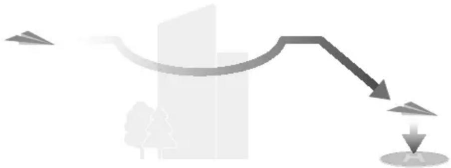
- If the lighting is sufficient and the environment is suitable for the vision system, the aircraft will automatically plan the optimal RTH path and adjust the altitude according to environmental factors, such as obstacles and transmission signals, regardless of the RTH Altitude setting. The optimal RTH path means the aircraft will travel the shortest distance possible to reduce the amount of battery power used and to increase flight time.
• If the lighting is insufficient or the environment is not suitable for the vision system, the aircraft will perform Preset RTH based on the RTH Altitude setting.
- Preset:
![graph TD A["Start"] --> B{Decision} B -->|Yes| C["Process Step"] B -->|No| D["End"]](/content/2026/08/1627030/images/faa2822fa48e59af41e7cea4fac431a73536d0f73041dab85e1e01f8eac09bed.jpg)
| RTH Distance/Altitude | Suitable Lighting and Environment Conditions | Unsuitable Lighting and Environment Conditions | |
| RTH distance >50 m | Current altitude < RTH altitude | The aircraft will plan the RTH path, fly to an open area while bypassing obstacles, ascend to the RTH Altitude, and return to home using the best path. | The aircraft will ascend to the RTH altitude, and fly to the Home Point in a straight line at the RTH altitude. [1] |
| Current altitude ≥ RTH altitude | The aircraft will return to home using the best path at the current altitude. | The aircraft will fly to the Home Point in a straight line at the current altitude. | |
| RTH distance is within 5-50 m | |||
[1] If the forward-facing LiDAR detects an obstacle ahead, the aircraft will ascend to avoid the obstacle. It will stop climbing once the path ahead is clear and then continue to RTH. If the obstacle height exceeds the altitude limit, the aircraft will brake and hover, and the user will need to take control.

- When Return to Home is set to Preset, a Direct Landing option will appear. When enabled, aircraft will directly land when arrives above the Home Point.
When the aircraft is approaching the Home Point, if the current altitude is higher than the RTH altitude, the aircraft will intelligently decide whether to descend while flying forward according to the surrounding environment, lighting, the set RTH altitude, and the current altitude. When the aircraft reaches the area above the Home Point, the current altitude of the aircraft will not be lower than the set RTH altitude.
The RTH plans for different environments, RTH trigger methods, and RTH settings are as follows:
| RTH Trigger Method | Suitable Lighting and Environment Conditions(The aircraft can bypass obstacles and GEO zones) | Unsuitable Lighting and Environment Conditions |
| The user actively triggers RTH | The aircraft will execute RTH based on the RTH setting:• Optimal• Preset | Preset (The aircraft can ascend to bypass obstacles and GEO zones) |
| Aircraft low battery | ||
| Loss of remote controller signal | Original route RTH,Preset RTH will be executed when the signal is restored (The aircraft can bypass GEO zones and will brake and hover if there is obstacle) |
Landing Protection
During RTH, landing protection activates once the aircraft begins to land.
The specific performance of the aircraft is as follows:
- If the ground is determined suitable for landing, the aircraft will land directly.
- If the ground is determined unsuitable for landing, the aircraft will hover and wait for pilot confirmation.
- If landing protection is not operational, DJI Pilot 2 will display a landing prompt when the aircraft descends to 0.5 m from the ground. Tap Confirm or push the throttle stick all the way down and hold for one second, and the aircraft will land.

• After reaching the area above the Home Point, the aircraft will land precisely on the takeoff point. Performing a precision landing is subject to the following conditions:
- The Home Point must be recorded upon takeoff and must not be changed during flight.
- During takeoff, the aircraft must vertically ascend at least 7 m before moving horizontally.
• The Home Point terrain features must remain largely unchanged. - The terrain features of the Home Point must be sufficiently distinctive. Terrain such as a snow-covered field is not suitable.
• The lighting conditions must not be too bright or too dark.
- During landing, movement of any other control stick apart from the throttle stick will be regarded as giving up precision landing, and the aircraft will descend vertically.
4.10 Sensing System
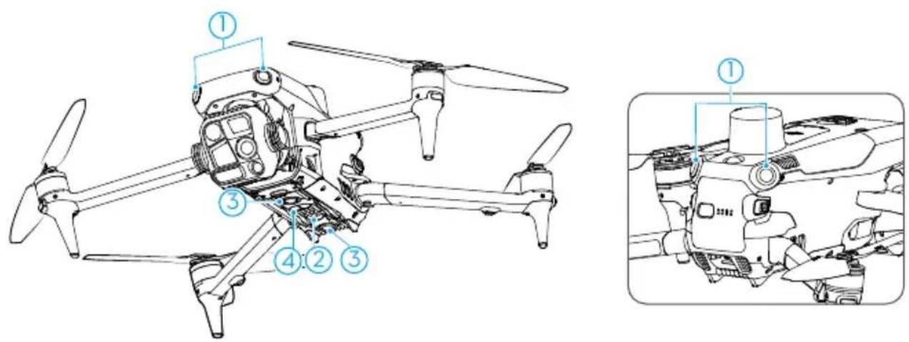
- Omnidirectional Vision System
-
Auxiliary Light
-
Downward Vision System
- 3D Infrared Sensing System
The omnidirectional vision system works best with adequate lighting and clearly marked or textured obstacles. The omnidirectional vision system will activate automatically when the aircraft is in Normal or Tripod mode and Obstacle Avoidance Action is set to Avoid or Brake in DJI Pilot 2. The positioning function is applicable when GNSS signals are unavailable or weak.
The auxiliary light located at the bottom of the aircraft can assist the downward vision system. It will automatically turn on by default in low-light environments when the flight altitude is under 5 m after takeoff. You can also turn it on or off manually in the DJI Pilot 2 app. Each time the aircraft is restarted, the auxiliary light will revert back to the default setting Auto.

- When Vision Positioning and Obstacle Sensing are disabled, the aircraft relies only on GNSS to hover, omnidirectional obstacle sensing is unavailable, and the aircraft will not automatically decelerate during descent close to the ground. Extra caution is required when Vision Positioning and Obstacle Sensing are disabled.
- Disabling Vision Positioning and Obstacle Sensing takes effect only when flying manually, and will not take effect when using auto modes such as RTH, or auto landing.
Notice

- Pay attention to the flight environment. The sensing system only works in certain scenarios and cannot replace human control and judgment. During a flight, always pay attention to the surrounding environment and the warnings in DJI Pilot 2, and be responsible for and maintain control of the aircraft at all times.
- If there is no GNSS available, the downward vision system will assist with aircraft positioning, and works best when the aircraft is at an altitude from 0.5 m to 30 m. Extra caution is required if the altitude of the aircraft is above 30 m as the vision positioning performance may be affected.
- In low-light environments, the vision system may not achieve optimal positioning performance even if the auxiliary light is turned on. Fly with caution if the GNSS signal is weak in such environments.
- The downward vision system may not work properly when the aircraft is flying near water. Therefore, the aircraft may not be able to actively avoid water below it when landing. It is recommended to maintain flight control at all times, make reasonable judgments based on the surrounding environment, and avoid over-relying on the downward vision system.
- The vision system cannot accurately identify large structures with frames and cables, such as tower cranes, high-voltage transmission towers, high-voltage transmission lines, cable-stayed bridges, and suspension bridges.
-
The vision system cannot work properly near surfaces without clear pattern variations or where the lighting is too weak or too strong. The vision system cannot work properly in the following situations:
-
Flying near monochrome surfaces (e.g., pure black, white, red, or green).
• Flying near highly reflective surfaces.
• Flying near water or transparent surfaces. - Flying near moving surfaces or objects.
• Flying in an area with frequent and drastic lighting changes.
• Flying near extremely dark (<0.5 lux) or bright (>40,000 lux) surfaces. - Flying near surfaces that strongly reflect or absorb infrared waves (e.g., mirrors).
• Flying near surfaces without clear patterns or textures. -
Flying near surfaces with repeating identical patterns or textures (e.g., tiles with the same design).
-
Flying near obstacles with small surface areas (e.g., tree branches, and power lines).
- Keep the sensors clean at all times. DO NOT scratch or tamper with the sensors. DO NOT use the aircraft in dusty or humid environments.
- The vision system cameras may need to be calibrated after being stored for an extended period. A prompt will appear in DJI Pilot 2 and calibration will be performed automatically.
- DO NOT fly when it is rainy, smoggy, or the visibility is lower than 100 m.
- DO NOT obstruct the sensing system.
- Check the following each time before takeoff:
• Make sure there are no stickers or any other obstructions over the glass of the sensing system.
- Use a soft cloth if there is any dirt, dust, or water on the glass of the sensing system. DO NOT use any cleaning product that contains alcohol.
- Contact DJI Support if there is any damage to the lenses of the sensing system.
- The aircraft can fly at any time of the day or night. However, the vision system becomes unavailable when flying the aircraft in low-light environments. Fly with caution.
Vision Assist
The vision assist view changes the image on the view from the corresponding vision sensors according to the flight speed direction to help users navigate and observe obstacles during flight.

- When using vision assist, the quality of the video transmission may be lower due to transmission bandwidth limits, or the video transmission resolution of the screen on the remote controller.
- It is normal for propellers to appear in the vision assist view.
- Vision assist should be used for reference only. Glass walls and small objects such as tree branches, electric wires, and kite strings cannot be displayed accurately.
- Vision assist is not available when the aircraft has not taken off or when the video transmission signal is weak.
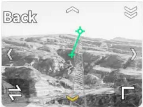
Tap the arrow to switch between different directions of the vision assist view. Tap and hold to lock the direction. Tap the center of the screen to maximize the vision assist view.

- When the direction is not locked in a specific direction, the vision assist view automatically switches to the current flight direction. Tap any other directional arrow to switch the direction of the vision assist view for a while before returning to the view of the current flight direction.
- When the vision assist direction is locked in a specific direction, tap any other arrow to unlock and switch the vision assist view.

- Tap the vision assist view in the camera view to enlarge it and the flight assistance functions will be displayed on the screen. Refer to Primary Flight Display for more information.
4.11 Advanced Pilot Assistance Systems
The Advanced Pilot Assistance Systems (APAS) feature is available in Normal mode and Cine mode. When APAS is enabled, the aircraft will continue to respond to your commands and plan its path according to both control stick inputs and the flight environment. APAS makes it easier to avoid obstacles, obtain smoother footage, and give a better flying experience.
When APAS is enabled, the aircraft can be stopped by pressing the Flight Pause button on the remote controller. The aircraft brakes and hovers for three seconds and awaits further pilot commands.
To enable APAS, open DJI Pilot 2, go to *** > Ⓐ, and select Avoid in Obstacle Avoidance.
Notice

- Make sure to use APAS when the vision system is available. Pay attention to DJI Pilot 2 and make sure APAS is working normally.
- Make sure there are no people, animals, objects with small surface areas (e.g., tree branches), or transparent objects (e.g., glass or water) along the desired flight path.
- Make sure to use APAS when the downward vision system is available or the GNSS signal is strong. APAS may not function properly when the aircraft is flying over water or snow-covered areas.
- Be extra cautious when flying in extremely dark (<300 lux) or bright (>10,000 lux) environments.
- APAS may not function properly when the aircraft is flying near flight limits or in a GEO zone.
- When the lighting becomes insufficient and the vision system is partially unavailable, the aircraft will switch from bypassing obstacles to braking and hovering. You need to center the control stick and then to continue controlling the aircraft.
Landing Protection
If Obstacle Avoidance Action is set to Avoid or Brake, Landing Protection will be activated when you push the throttle stick down to land the aircraft. Landing Protection is enabled once the aircraft begins to land.
- If the ground is determined to be suitable for landing, the aircraft will land directly.
- If the ground is determined to be unsuitable for landing, the aircraft will hover when the aircraft descends to a certain height above ground. Push down on the throttle stick for at least five seconds, and the aircraft will land without obstacle sensing.
4.12 DJI AirSense
Airplanes with an ADS-B transceiver will actively broadcast flight information including locations, flight paths, speeds, and altitudes. DJI aircraft incorporated with the DJI AirSense technology are capable of receiving flight information broadcast from ADS-B transceivers that comply with 1090ES or UAT standards within a radius range of 10 kilometers. Based on the received flight information, DJI AirSense can analyze and obtain the location, altitude, orientation, and velocity of the surrounding manned airplanes, and compare such figures with the current position, altitude, orientation, and velocity of the
DJI aircraft to calculate in real time the potential risk of collision with the surrounding manned airplanes. DJI AirSense will then display a warning message in DJI Pilot 2 according to the risk level.
DJI AirSense only issues warning messages on approaches by specific manned airplanes under special circumstances. Please be aware that DJI AirSense has the following limitations:
- DJI AirSense can only receive messages sent by airplanes installed with an ADS-B Out device that is in compliance with 1090ES (RTCA DO-260) or UAT (RTCA DO-282) standards. DJI devices cannot receive broadcast messages from or display warnings on airplanes not equipped with properly functioning ADS-B Out devices.
- If there is an obstacle between a manned aircraft and a DJI aircraft, DJI AirSense will not be able to receive ADS-B messages from the aircraft or send warnings to the user. Keenly observe your surroundings and fly with caution.
- Warning prompts may be sent with delay if DJI AirSense experiences any interference from the surrounding environment. Keenly observe your surroundings and fly with caution.
- Warning prompts may not be received if the DJI aircraft is unable to obtain information on its own location.
- DJI AirSense cannot receive ADS-B messages from manned airplanes or send warnings to the user when it is disabled or misconfigured.
When a risk is detected by the DJI AirSense system, the AR projection display will appear on the current view in DJI Pilot 2, intuitively showing the distance between the DJI aircraft and the airplane, and issuing a warning alert. Users should follow the instructions in DJI Pilot 2 upon receiving the alert.
Notice: A blue airplane icon will appear on the map.
Caution: The app will display the message Manned aircraft detected nearby. Fly with caution. A small orange square icon with the distance information will appear on the camera view, and an orange airplane icon will appear on the map view.
Warning: The app will display the message Collision risk. Descend or ascend immediately. If the user is not operating, the app will display Collision risk. Fly with caution. A small red square icon with the distance information will appear on the camera view, and a red airplane icon will appear on the map view. The remote controller will vibrate to alert.
4.13 Expansion Port
The aircraft is equipped with an E-Port to support PSDK, enabling more feature development. Visit https://developer.dji.com for more information about SDK development and instructions.
5 Remote Controller
5.1 Charging the Battery

- Fully discharge and charge the remote controller every three months. The battery depletes when stored for an extended period.

- It is recommended to use the included USB-C to USB-C cable for optimal charging.
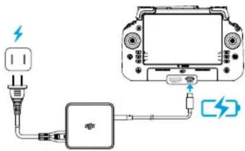
Checking the Battery Level
Press the power button on the remote controller once to check the internal battery level.
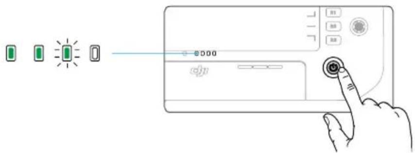
The C1, C2, C3, C4 and 5D buttons are customizable. Open DJI Pilot 2 and enter camera view. Tap ⋯ to configure the functions of these buttons. In addition, combinations can be customized using the C1, C2, and C3 buttons with the 5D button.
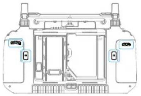
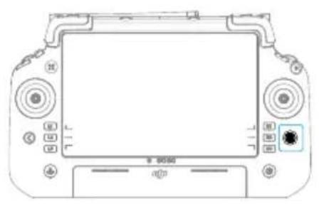
5.3 Button Combinations
Some frequently used features can be activated by using combination buttons. To use combination buttons, press and hold the back button and operate the other button in the combination.
The default button combinations cannot be changed. The following table displays the function of each default button combination.
Combination Operation Function
Back Button + Left Dial Adjust Brightness
Back Button + Right Dial Adjust Volume
Back Button + Record Button Record Screen
Back Button + Shutter Button Screenshots
Back Button + 5D Button Toggle up - Homepage; Toggle down -
Shortcut settings; Toggle left - Recently opened apps.
5.4 Operating the Touchscreen
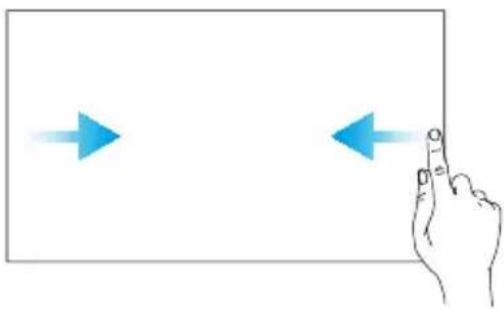
Slide from the left or right to the center of the screen to return to the previous screen.
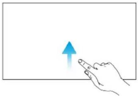
Slide up from the bottom of the screen to return to the homepage.
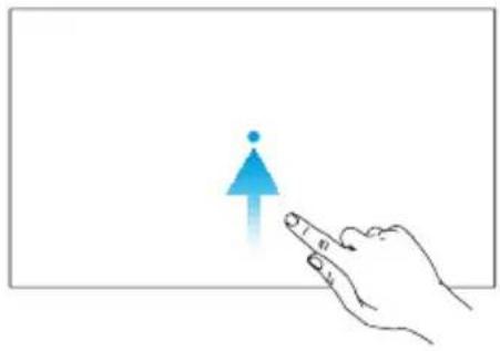
Slide up from the bottom of the screen and hold to access recently opened apps.
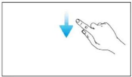
Slide down from the top of the screen to open the status bare when in DJI Pilot 2. The status bar displays information such as time, Wi-Fi signal, and remote controller battery level.
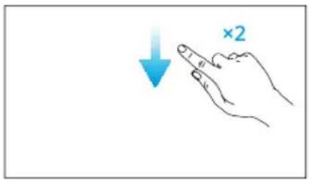
Slide down twice from the top of the screen to open Quick Settings when in DJI Pilot 2. Slide down once from the top of the screen to open Quick Settings when not in DJI Pilot 2.
5.5 Remote Controller LEDs
Status LED
Blinking Pattern Descriptions

Solid red Disconnected from the aircraft.

Blinks red The battery level of the aircraft is low.

Solid green Connected with the aircraft.

Blinks blue The remote controller is linking to an aircraft.

Solid yellow Firmware update failed.
| Blinking Pattern Descriptions | |
| — | Solid blue Firmware update successful. |
| ...... | Blinks yellow The battery level of the remote controller is low. |
| ...... | Blinks cyan Control sticks not centered. |
Battery Level LEDs
The battery level LEDs indicate the battery level of the remote controller.
| Blinking Pattern Battery Level | |
| 88-100% | |
| 75-87% | |
| 63-74% | |
| 50-62% | |
| 38-49% | |
| 25-37% | |
| 13-24% | |
| 0-12% |
5.6 Remote Controller Alert
The remote controller beeps to indicate an error or warning. Pay attention when prompts appear on the touchscreen or in DJI Pilot 2.
Slide down from the top of the screen and select Mute to disable all alerts, or slide the volume bar to 0 to disable some alerts.
The remote controller sounds an alert during RTH, which cannot be cancelled. The remote controller sounds an alert when the battery level of the remote controller is low. A low battery level alert can be cancelled by pressing the power button. When the battery level is critically low, the alert cannot be cancelled.
There will be an alert if the remote controller is not used for a period of time while it is powered on but is not connected to the aircraft. It will automatically power off after the alert stops. Move the control sticks or press any button to cancel the alert.
5.7 Optimal Transmission Zone
Unfold and adjust the antennas. The strength of the remote controller signal is affected by the position of the antennas.
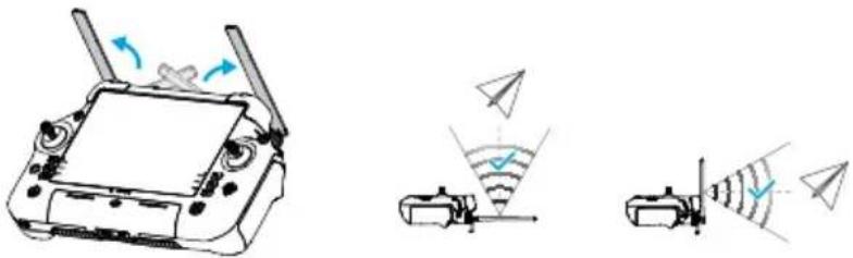
Adjust the direction of the external RC antennas of the remote controller and make sure their flat side is facing the aircraft, so that the controller and aircraft are within the optimal transmission zone.

- DO NOT overstretch the antennas to avoid damage. Contact DJI Support to repair the remote controller if the antennas are damaged. A damaged antenna will greatly decrease the performance of the remote controller and might affect flight safety.
- During flight, DO NOT use other 2.4 GHz or 5.8 GHz communication devices in the same frequency band at the same time, so as not to interfere with the communication signal of the remote controller. For example, avoid enabling mobile phone Wi-Fi.
- A prompt will appear in DJI Pilot 2 if the transmission signal is weak during flight. Adjust the antennas to make sure that the aircraft is in the optimal transmission range.
5.8 Linking the Remote Controller
The remote controller is already linked to the aircraft when purchased together as a combo. Otherwise, follow the steps below to link the devices.
Method 1: Using Combination Buttons
- Power on the aircraft and the remote controller.
- Press the C1, C2, and Record buttons simultaneously until the status LED blinks blue and the remote controller beeps.
- Press and hold the power button of the aircraft for at least five seconds. The aircraft beeps, and its battery level LEDs blink in sequence to indicate it is ready to link. The remote controller will beep twice, and its status LED will turn solid green to indicate linking is successful.
Method 2: Using App
- Power on the aircraft and the remote controller.
- Run DJI Pilot 2 and tap Link Remote Controller to link. The status LED of the remote controller blinks blue, and the remote controller will beep during linking.
- Press and hold the power button of the aircraft for at least five seconds. The aircraft beeps, and its battery level LEDs blink in sequence to indicate it is ready to link. The remote controller will beep twice, and its status LED will turn solid green to indicate linking is successful.

- Make sure the remote controller is within 0.5m of the aircraft during linking.
- Make sure the remote controller is connected to the internet when logging in using a DJI account.
5.9 HDMI Settings
The touchscreen can be shared to a display after connecting the HDMI port of the remote controller.
The resolution can be set by entering ⚙ > Display > HDMI.
6 DJI Pilot 2 App
6.1 Homepage
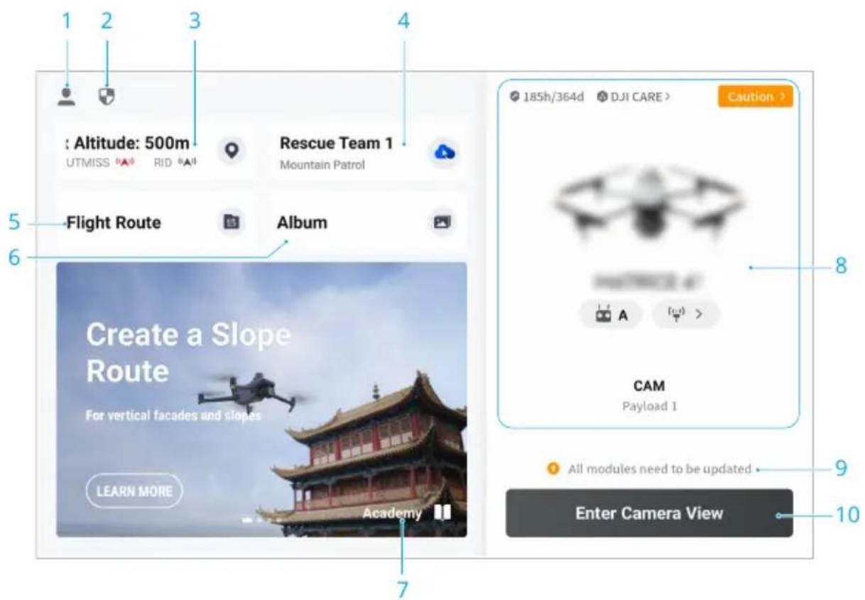
1. Profile
Tap to view flight records, download offline maps, manage GEO Zone unlocking, read help documentation, select a language, and more.
2. Data and Privacy
Tap to manage network security modes, set security codes, manage app cache, and clear DJI device logs.
3. GEO Zone Map
Tap to view whether the current operating area is in a restricted zone or authorization zone, and the current flyable altitude.
4. Cloud Service
Tap to view the connection status of the cloud service, select the type of service, or switch from the currently connected service to another cloud service.

- If the DJI account logged in by the user has the DJI FlightHub 2 license, tap the cloud service on the app homepage to automatically log in to DJI FlightHub 2.
Visit the DJI FlightHub 2 page on the DJI official website for more information: https://www.dji.com/flighthub-2.
5. Flight Route
Tap to enter the flight route library. Users can create and view all flight tasks. Flight tasks can be imported and exported in batches to the remote controller or another external mobile storage device. If DJI FlightHub 2 is connected, you can also view all flight tasks sent from the cloud or upload local tasks to the cloud.
- Album
- Academy
- Health Management System
- Firmware Update Shortcut

- A consistent firmware update is required when the firmware versions of some modules of the aircraft are inconsistent with the compatible version of the system.
- Enter Camera View
6.2 Camera View
Top Bar

- Back
- System Status Bar
If a new alert appears during flight, it will be displayed here and continue flashing. Tap to view the information and stop the flashing.
- Flight Status
Tap to enter the Preflight Check view.
4. Battery Level Indicator Bar
Displays the battery level and the remaining flight time of the Intelligent Flight Battery after takeoff.
5. GNSS Positioning Status
Displays the number of searched satellites. When the RTK service is not enabled, the RTK icon is gray. When the RTK data is converged, the RTK icon will turn white. Tap the GNSS positioning status icon to view the RTK mode and GNSS positioning information.
6. Signal Strength
7. Intelligent Flight Battery Level
Displays the battery level of the aircraft. Tap to view battery level, voltage, and temperature.
8. Settings
Tap to expand the settings menu to set the parameters of each module.
Navigation Display
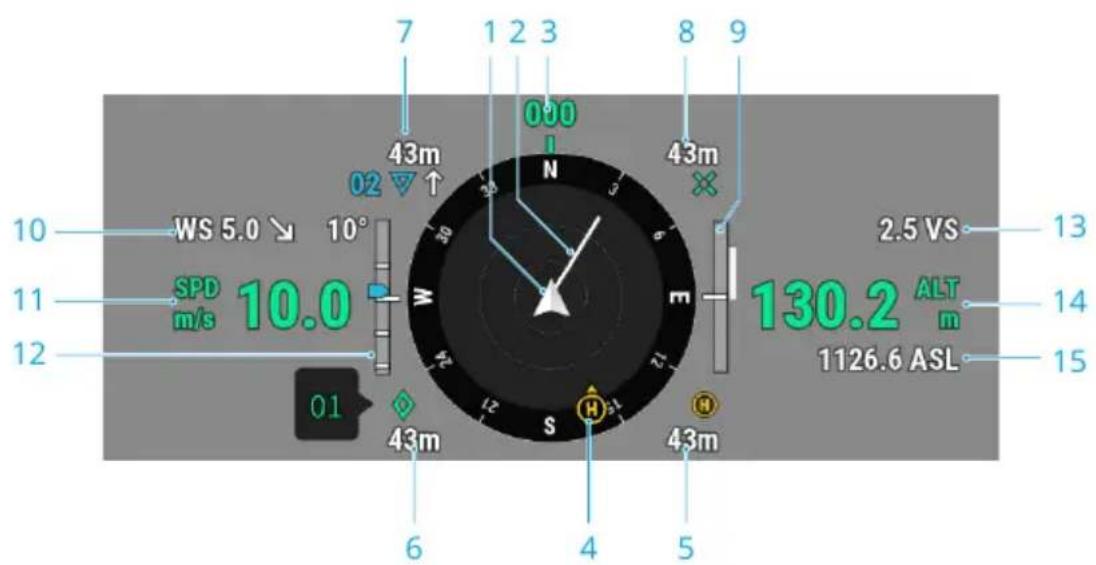
-
Aircraft
-
Aircraft Horizontal Speed Vector
The white line drawn by the aircraft indicates the flight direction and speed of the aircraft.
- Aircraft Orientation
Displays the current orientation of the aircraft, with 0 degrees as North on the compass.
4. Home Point and Remote Controller Orientations
- Displays the position of the Home Point (yellow H) and the remote controller (blue dot) relative to the aircraft.
- If the remote controller and the Home Point are close to each other, only the Home Point will be displayed.
- The remote controller dot features an arrow to indicate the orientation. If the signal is weak during flight, adjust the remote controller's direction so that the arrow points towards the aircraft.
5. Home Point Distance
Displays the horizontal distance between the Home Point and the aircraft.
6. PinPoint Information
Displays the name of the PinPoint and the horizontal distance from the aircraft to the PinPoint, when PinPoint is enabled.
7. Waypoint Information
Displays the name of the waypoints, the horizontal distance from the aircraft to the waypoint, and the ascending or descending trajectory of the flight route, during a flight route.
8. RNG Target Point Information
Displays the horizontal distance from the aircraft to the target point, when the RNG laser rangefinder is enabled.
9. Vertical Obstacle Sensing Information
Once an obstacle is detected in the vertical direction, an obstacle bar icon will appear. When the aircraft reaches the warning distance, the icon will glow red and orange, and the remote controller will emit long beeping sounds. When the aircraft reaches the obstacle braking distance, the icon will glow red, and the remote controller will emit short beeping sounds. Both the obstacle braking distance and the warning distance can be set in DJI Pilot 2. Follow the prompted instructions in the app to set them. The white line shows the position of the aircraft in three seconds. The higher the vertical speed, the longer the white line.
Horizontal Obstacle Sensing Information
The light areas are the obstacle sensing areas of the aircraft, while the dark areas are the blind spots. During flight, keep the aircraft speed vector line out of the obstacle-sensing blind spots.
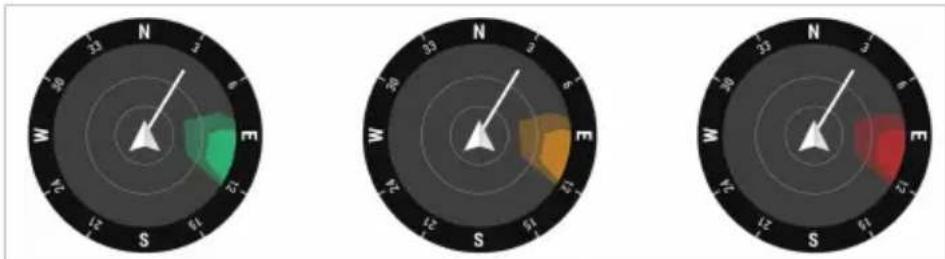
- If an obstacle is detected, it will be indicated by a green frame when it is outside the warning distance. When the obstacle reaches the warning distance, the frame turns orange. When the obstacle approaches the obstacle braking distance, the frame turns red.
- When the obstacle sensing is disabled, OFF will be displayed. When obstacle sensing is enabled, the vision system is not working but infrared sensing system is available, TOF will be displayed. When the obstacle sensing is enabled, but the vision system and the infrared sensing system are not available, NA will be displayed.
- Wind Speed and Direction
The wind direction is relative to the aircraft.
-
Aircraft Horizontal Speed
-
Gimbal Tilt
-
Aircraft Vertical Speed
-
Relative Altitude (ALT)
Displays the altitude of the aircraft relative to the takeoff point.
- Altitude (ASL)
Zoom Camera View
Below is an illustration using the zoom camera as the main view.
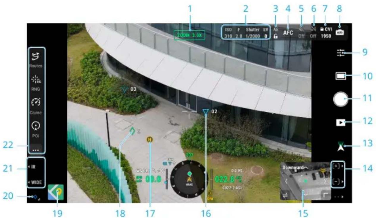
- Camera Type
- Camera Parameters
- Auto Exposure Lock
- Focus Mode
- Night Scene Mode
- Electronic Dehazing
- Storage Info
- Camera Mode
- Camera Settings
- Photo/Video Mode
- Shutter/Record Button
- Playback
- Gimbal Mode
- Vision Assist
- Waypoints
-
Home Point
-
Press the R1/R2 button on the remote controller to control the camera zoom.
In a flight task, the two waypoints that the aircraft is about to pass will be projected on the camera view.
-
PinPoints
-
Map View
-
PinPoint Function
Press the L3 button on the remote controller to add a PinPoint in the center of the screen. Press and hold on the L3 button to expand the PinPoint settings panel.
-
Press the L1/L2 button on the remote controller to switch the camera lens.
-
Customizable Function Bar
Tap to access more functions, and it supports custom panels.
Wide-Angle Camera View
This section mainly sets out the differences with zoom camera. Refer to the Zoom Camera View section for more details.
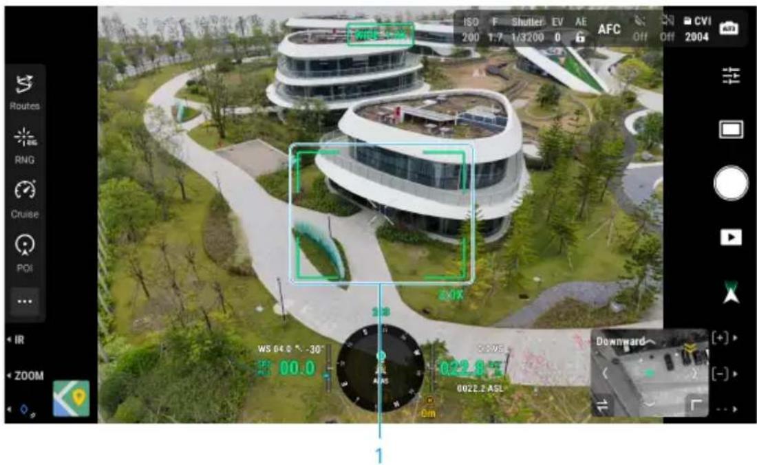
1. Zoom Frame
After switching to the wide-angle camera as the main view, the zoom frame will display the field of view and camera zoom ratio.
Thermal Camera View
This section mainly sets out the differences with zoom camera. Refer to the Zoom Camera View section for more details.
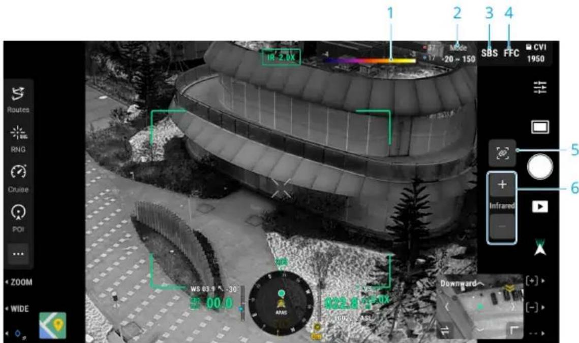
1. Palette
Displays the highest and lowest temperature measurement values of the current view. Tap to choose between different infrared temperature measurement palettes, or enable the isotherm to set temperature measurement intervals. Note that if the measured area exceeds the maximum or minimum temperature measurement values of the current view, the setting will not take effect.
2. Gain Mode
3. SBS
The infrared screen is set as single infrared view by default. Tap to enable or disable side-by-side view. When enabled, both the footage captured by the thermal camera and the zoom camera will be displayed side by side.
4. FFC
Tap to start FFC calibration. FFC calibration is a function of the thermal camera that optimizes image quality for easy observation of temperature changes.
5. Link Zoom
Tap to link the lenses of the thermal camera and zoom camera to zoom. The user can view the linked zoom effect by enabling the SBS button in the thermal camera view.
6. Thermal Camera Zoom

- Tap on the screen or select an area to perform spot temperature measurement or area temperature measurement.
Laser Rangefinding
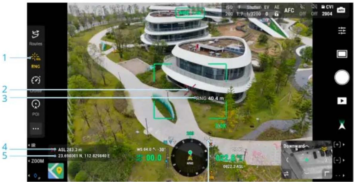
6
- Tap to enable the RNG.
- The cross hair in the center of the lens will turn red, which means the laser rangefinder is aiming at the target and measuring the altitude of the target and distance between the target and the aircraft. The latitude and the longitude of the target can be obtained after a PinPoint is created on the target.
- The linear distance between the target and the aircraft.
- The altitude of the target.
- The latitude and longitude of the target.
- The horizontal distance between the target and the aircraft.

- RNG positioning is limited by factors such as the GNSS positioning accuracy and gimbal attitude accuracy. The GNSS position, horizontal distance, navigation display, and AR projection are provided for reference only.
• The shape of the cross hairs varies with different camera lenses.
Primary Flight Display
Primary Flight Display (PFD) makes flying easier and more intuitive, enabling users to see and avoid obstacles around the aircraft, as well as stop and adjust the flight trajectory if necessary.
The Primary Flight Display may appear differently when the main view is through an FPV camera or a gimbal camera (zoom camera/wide camera/thermal camera).
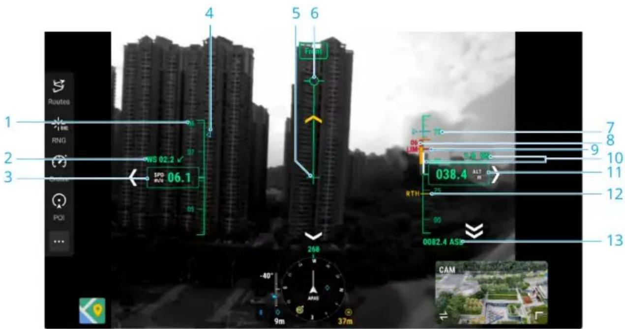
-
Speed Wheel
-
Wind Speed and Direction
The wind direction is relative to the aircraft.
-
Aircraft Horizontal Speed
-
Preset speed of the flight route during the flight task.
-
Aircraft Heading Indicator
-
Flight Path Vector
The position the aircraft is about to reach.
-
Preset height of the flight route during the flight task.
-
Vertical Obstacle Indicator
When there is an obstacle above or below the aircraft, you can refer to the obstacle sensing display or compare the speed bar with the obstacle height to determine if a collision is imminent and avoid accidents.
-
Altitude Limit (LIM)
-
Aircraft Vertical Speed
The white line shows the position of the aircraft in three seconds. The higher the vertical speed, the longer the white line.
- Relative Altitude (ALT)
The altitude of the aircraft relative to the takeoff point.
- Return-to-Home Altitude (RTH)
- Altitude (ASL)
7 Flight Operations
7.1 Annotation Management and Synchronization
PinPoint
PinPoint can be used to set the location point of a subject in gimbal camera view or map view, for quick observation and information synchronization.
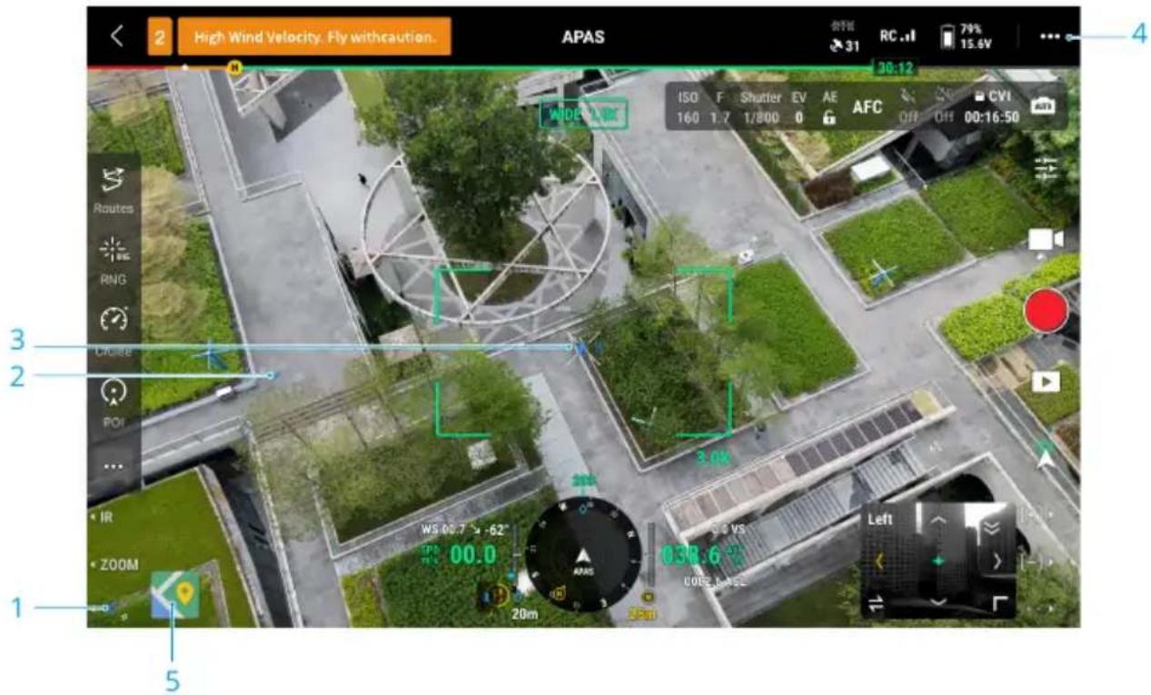
1. Create a PinPoint
Adjust the attitude of the aircraft and the gimbal to move the subject to the center of the current view. Press the L3 button of the remote controller to pin the subject at the center. The PinPoint can record the latitude, longitude and altitude of the subject.
- AR projection will be created for the subject in gimbal camera view or FPV camera view. It will be big when near, small when far.
3. Selected PinPoint
- A small frame will appear around the PinPoint, indicating it is selected.
-
The lower left corner of the Navigation Display shows the horizontal distance from the PinPoint to the aircraft and the name of the PinPoint. The orientation of the PinPoint relative to the aircraft is also shown within Navigation Display.
-
If the selected PinPoint is outside the video transmission view, the PinPoint icon will stay on the edge of the screen, indicating its orientation relative to the center of the view.
• After selecting a PinPoint, the user can edit the PinPoint or drag the PinPoint on the map. -
Tap ▷ to set the remote controller's custom buttons to the PinPoint related functions. Users can quickly create and select PinPoints by using the buttons.
-
Switch to Map View
In map view, you can add a PinPoint by dragging the point to the crosshairs in the center of the map. The altitude is the current flight altitude of the aircraft.

- PinPoint positioning is limited by factors such as the GNSS positioning accuracy and gimbal attitude accuracy. The latitude and longitude, horizontal distance, Navigation Display, and AR projection are provide for reference only.
Line and Area Annotation Management
Users can draw lines and areas on the map to synchronize key information about roads and land.
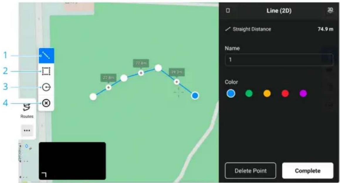
- Tap to display the Edit Line view.
- Tap to display the Edit Area view.
- Tap to display the Edit Circle view.
- Clear all annotations.
Annotation Sharing
The location of the target point identified by PinPoint can be synchronized with the camera view, Navigation Display, map view, and DJI FlightHub 2. It can be displayed on both camera and map views.
When connected to DJI FlightHub 2, the point, line and area annotations of DJI Pilot 2 app and DJI FlightHub 2 can be synchronized with each other. Locations and annotations can be viewed on the remote controller and other devices logged into DJI FlightHub 2 for real-time sharing.
7.2 Intelligent functions
DJI Matrice 4 Series Support multiple intelligent flight modes such as Smart Track, Cruise, and features such as AI-based object detection and observation data record.

Click the link below or scan the QR code to watch the tutorial video before first time use.
https://enterprise.dji.com/matrice-4-series/video
POI
After enabling the POI mode, the aircraft flies around the selected PinPoint in a circle, making it convenient for users to take orbit shots. POI can be enabled only when the aircraft is in Normal mode.
In POI mode, if the vision systems are working normally, the aircraft will brake when an obstacle is detected, regardless of whether obstacle avoidance is set to Avoid or Brake.
Usage
- After takeoff, select an existing PinPoint from the camera view or the map view or create a new PinPoint after finding the subject.
- Manually control the aircraft to adjust the radius.
- Tap the POI icon in the camera view to enable the POI mode. The aircraft looks at the selected PinPoint automatically.

- As the PinPoint has altitude, when the aircraft looks at the PinPoint, it will look at the altitude of the PinPoint. To look at the subject right below the PinPoint, lock or adjust the gimbal angle manually after tapping the POI icon.
- Move the roll stick left or right to make the aircraft start to fly clockwise or counterclockwise. The more the stick is pushed away from the center position, the faster the aircraft will move.
- Once the desired speed has been reached, press the C1 button on the remote controller or tap in the camera view to set the current speed as the POI speed. The aircraft will automatically circle at the POI speed.
- While the aircraft is circling automatically, users can move the roll stick left or right to decrease or increase the circling speed. Once the desired speed has been reached, press the C1 button on the remote controller or tap C1 in the camera view to set the updated speed as the POI speed. The aircraft will automatically circle at the new POI speed.
- Tap the shutter/record button to take photos or start recording.
- Press the flight pause button or the C1 button once on the remote controller or tap in the camera view, the aircraft will brake and hover in place. Tap the POI icon in the camera view to exit the POI mode.

- Only Single and Timed photos and video recordings are supported in POI mode.
- The maximum circling speed changes based on the current circling radius. The larger the circling radius, the higher the maximum circling speed.
- While the aircraft is circling, if the user has changed the aircraft orientation with the yaw stick so that the aircraft does not look directly at the selected PinPoint, in this condition, if the user moves the pitch stick up and down, the aircraft will not fly forward or backward following current orientation. Instead, the aircraft will fly toward or away from the selected PinPoint.
7.3 Flight Tasks
Tap Flight Route on the homepage of DJI Pilot 2 to enter the flight route library, or tap the flight route icon ⚪ in the camera view or in the map view to enter the flight route library. Users can view flight tasks or create a flight task.
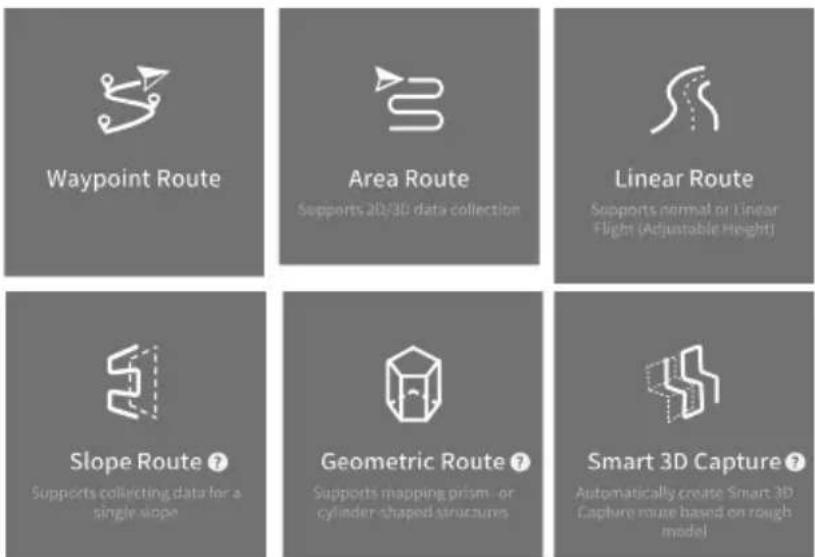
Waypoint Route
Waypoint Route can be planned in two ways: Set Waypoints or Live Mission Recording. Use Set Waypoints to create a route by adding and editing waypoints on the map. Use Live Mission Recording to create a route by adding waypoints when taking photos along the route.
Set Waypoints
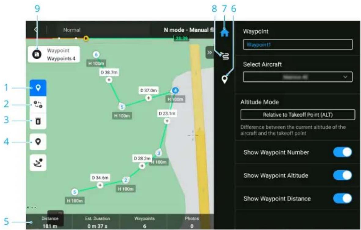
-
Enable/Disable Editing Waypoint on Map
-
Reverse Path
Tap to swap the start and end points to reverse the flight path. S refers to the start point.
-
Delete Selected Waypoint
-
Point of Interest (POI)
Tap to enable the POI function, and a POI will be displayed on the map. Drag to adjust its position. After a POI is added, the aircraft yaw can be set as facing the POI, so that the aircraft nose points at the POI during the task. Tap this icon again to disable the POI function.
-
Flight Route Information
-
Individual Waypoint Settings
-
Parameters List
-
Flight Route Settings
These parameters will take effect for all waypoints in the route.
- Save
Tap to save the flight route. After the flight route is saved, the icon becomes the perform task button, tap the button and then check the settings and status of the aircraft in the pop-up checklist. Tap to upload the flight route. Once the upload is complete, tap the Start button to perform the current task.
Live Mission Recording
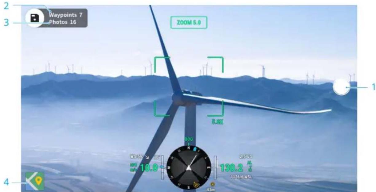
- Control the gimbal, adjust the zoom scale, and aim at the subject. Tap to capture photos or press the C1 button of the remote controller to add a waypoint. The number of waypoints and photos will be added accordingly.
- The number of planned waypoints.
- The number of planned photos.
- Tap to switch to map view for editing or viewing.
AI Spot-Check
Live mission recording supports AI Spot-Check. By selecting the target object in photos of the flight route, the aircraft will accurately take photo for the same object during its next flight.
When recording the flight route, it is recommended to place the target into the target selection box. When editing the flight route, select Drag-Select Target to enter the AI Spot-Check editing page.
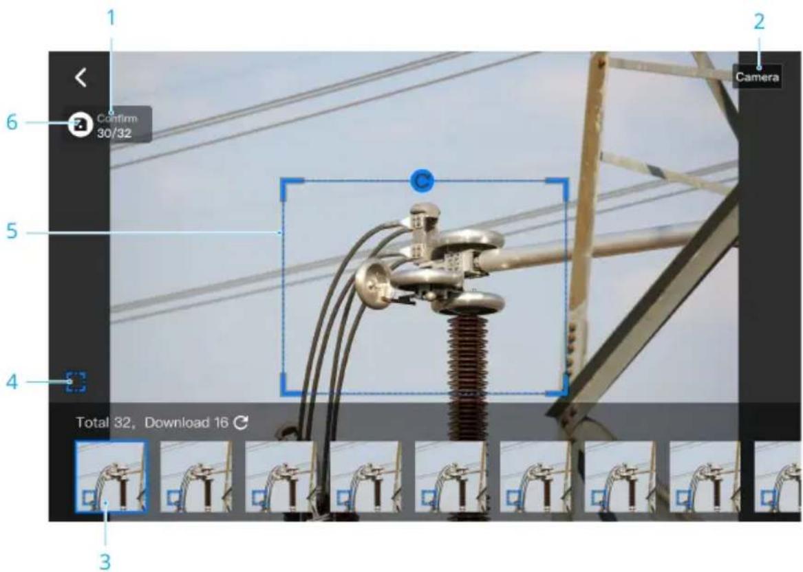
- Current photo number and total number of photos.
- The device used to take the photo.
- Photo thumbnail. Tap to perform AI Spot-Check editing for this photo. Photos requiring AI Spot-Check will have a frame mark.
- Enable/disable AI Spot-Check for the current photo.
- Target selection box. You can adjust the box size, drag or rotate the box.
- Save the flight route.

- AI Spot-Check can only be used with a zoom camera and requires taking photos within 10x zoom range.
- AI Spot-Check should be used when RTK is enabled, and the RTK base station coordinates for taking photos and re-flight must remain consistent.
Area Route
Area route has Ortho Collection and Oblique Collection, the aircraft can automatically complete the data collection for the aerial photogrammetry of the planned area along the s-shaped route according to the route parameters.
Oblique collection generates five s-shaped routes in the mapping area, respectively controlling the gimbal to collect orthophoto and oblique photos in 5 different directions, which can be used to make real 3D models.
Smart Oblique and Terrain Follow can be enabled in the area route.
Smart Oblique
Smart Oblique is an innovative oblique photography solution. By automatically controlling the gimbal to capture images from multiple angles, it greatly improves operational efficiency.
- During Ortho Collection, with Smart Oblique enabled, the gimbal supports simultaneous lateral capturing, reducing the flight route density and increasing data collection efficiency.
- During Oblique Collection, with Smart Oblique enabled, the gimbal can capture images in five directions simultaneously. The aircraft only needs to fly one flight route to collect the orthophoto and oblique photos required for 3D reconstruction.
Terrain follow
When collecting data in areas with large elevation differences, such as mountainous areas, Terrain Follow allows the aircraft to adjust the flight altitude following the changes in the terrain. Terrain Follow ensures that the relative height of the aircraft and the ground below remains unchanged so that the Ground Sampling Distance (GSD) of the photos collected in each area is consistent, improving the accuracy of mapping data while ensuring flight safety.

- Select AGL for the Altitude Mode to enable Terrain Follow.
Real-Time Follow
Real-Time Follow does not require DSM files. The aircraft vision system detects the terrain fluctuations ahead in real time during the flight. It is recommended to use this function in areas where the terrain slope is less than 75° and the lighting condition and environment are suitable for the vision system.
When performing a mapping task while Real-Time Follow is enabled, the aircraft altitude above ground level (AGL) and the terrain trend ahead of the aircraft will be displayed in the camera view.
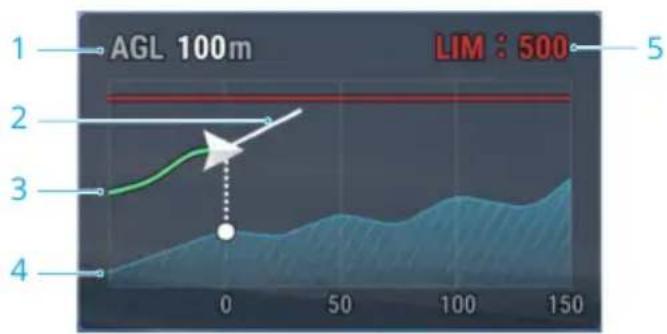
- Altitude above Ground Level (AGL)
- Aircraft Velocity Direction
- Flight Path
- Terrain Trend Line
- Max Altitude

- When flying beyond the long-distance detection range of the vision system, Real-Time Follow cannot be performed. Fly with caution. Real-Time Follow cannot work in locations that feature cliffs, steep slopes, power lines, and towers.
- The vision system cannot work properly in low-light environments. Real-Time Follow cannot be used normally in rainy, snowy, and foggy environments.
- The vision system may not work properly over water. Therefore, the aircraft may not be able to actively detect the distance to the water for real-time follow. It is not recommended to use real-time follow in large areas of water and ocean waves.
- The vision system cannot work properly near surfaces without clear pattern variations or where the light is too bright or too dark. The vision system cannot work properly in the following situations:
• Flying near monochrome surfaces (e.g., pure black, white, red, or green surfaces).
• Flying near highly reflective surfaces.
• Flying near water or transparent surfaces.
• Flying near moving surfaces or objects.
• Flying in an area with frequent and drastic lighting changes.
• Flying near extremely dark (<10 lux) or bright (>40,000 lux) surfaces.
- Flying near surfaces that strongly reflect or absorb infrared waves (e.g., mirrors).
• Flying near surfaces without clear patterns or textures.
- Flying near surfaces with repeating identical patterns or textures (e.g., tiles with the same design).
- Flying near obstacles with small surface areas (e.g., tree branches and power lines).
- Keep the sensors clean at all times. DO NOT tamper with the sensors. DO NOT use the aircraft in dusty or humid environments.
DSM Follow
By importing the DSM file, the app will generate a flight route with altitude changes. The DSM files of the mapping area can be obtained using the following two methods:
Import Local File
- Collect the 2D data of the mapping area and perform a 2D reconstruction using DJI Terra by selecting Fruit Tree mode. A .tif file will be generated and can be imported to the microSD card of the remote controller.
- Download the terrain mapping data from a geobrowser.
Download from Internet
DSM files can be directly obtained by downloading the open source data of the ASTER GDEM V3 geoid database.

- Make sure the DSM file is a geographic coordinate system file, not a projected coordinate system file. Otherwise, the imported file may not be recognized. It is recommended that the resolution of the imported file should be no more than 10 meters.
- Make sure that the mapping area is within the range of the DSM file.

- The open-source geoid database may have errors. DJI is not responsible for the accuracy, authenticity, or validity of the data. Pay attention to the flight environment and fly with caution.
Linear Route
Linear Route is used to collect orthophotos for strip-shaped areas such as rivers and pipelines. The mapping area can be generated by selecting the center line of the strip and extending outward along this line.
Set Waypoints
First, set Flight Band by selecting points on the map to generate the band-shaped mapping area, and confirm the center line and the scope of the mapping area. Switch to Flight Route to generate the corresponding s-shaped route, and adjust the route parameters to complete the setting.
Center line can be generated by tapping on the map or importing a linear KML file. Note: After the band-shaped area is generated, check along the path to see if there is a large deviation from the original mapping area. If there is a deviation, increase some points to cover the area completely or increase the length of the left and right extensions to cover the mapping area completely.
Terrain Follow can also be enabled in the Linear Route. Both Real-Time Follow and DSM Follow are available. Refer to Terrain follow section in Area Route for more information.
Live Mission Recording
Live Mission Recording is used to plan the route by adding waypoints as the center line of the flight area when the aircraft is close to the subject. Live Mission Recording for linear route supports an adjustable altitude during flight, which is suitable for scenarios such as channel inspection.

- To ensure flight safety, RTK needs to be connected when recording live mission and collecting aerial photogrammetry data.
Slope Route
Slope Route is used to collect photogrammetry data for a single elevation or slope, which is mainly used for modeling and inspection of building facades and slopes. By planning the spatial flight route and verifying the route safety with AR projection, users can collect modeling data.
Create Slope
- Adjust the aircraft and the camera to face the slope. Ensure the camera view is parallel to the slope.
- When the distance between the aircraft and the slope appears on the screen, press the C1 button on the remote controller to obtain the AR Slope and Route View.

- If the distance to the slope cannot be identified, move the aircraft left or right under safe circumstances to obtain additional spatial information.
• Make sure RTK is connected during the entire process of planning and performing Slope Route. Otherwise, the function cannot be used.
- Route Viewer is generated once slope is created and can be updated during the route planning process. Adjusting boundaries of the mapping area is available in Route Viewer.
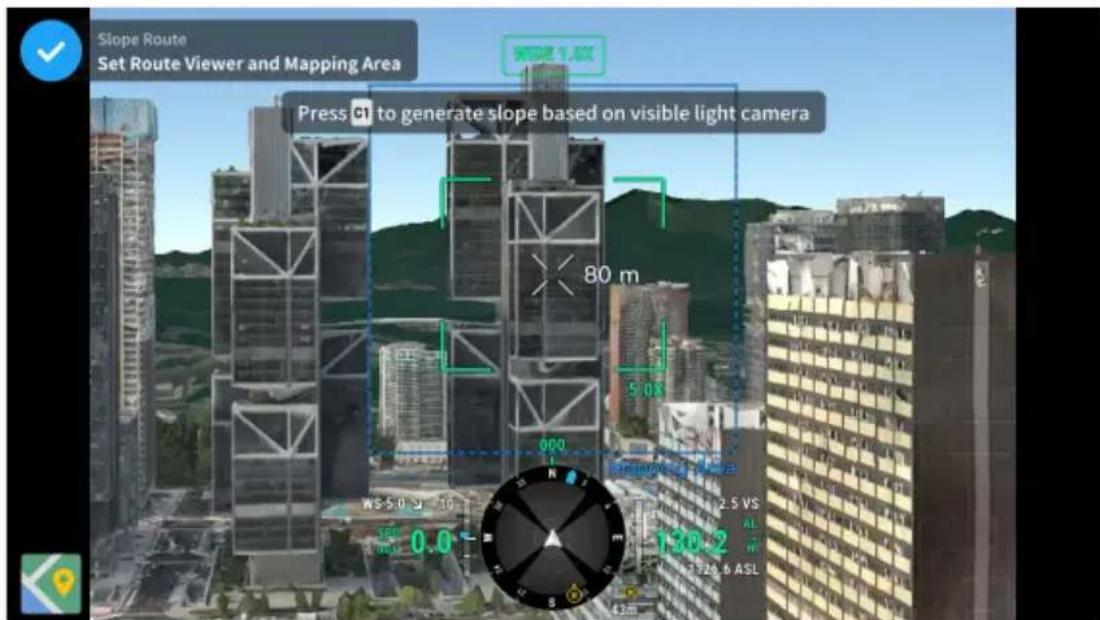
Adjust and Confirm AR Slope
-
To adjust the distance and angle between AR slope and actual slope to be mapped, fly the aircraft to the side of the AR slope. It is recommended that the AR slope fits the actual slope for more accurate GSD calculation.
-
Adjust the boundary points of the slope and add additional boundary points to modify the shape of the slope.
- Click Slide/Rotate Mapping Area to open the parameter settings panel for the mapping area. Users can adjust the mapping area angle and move the mapping area forward and backward.
-
If the angle and position of the Route Viewer is inappropriate, click in the lower right corner of the Route Viewer to reset.
-
When the AR slope matches the actual slope sufficiently, click √ to confirm the mapping area and generate a route.
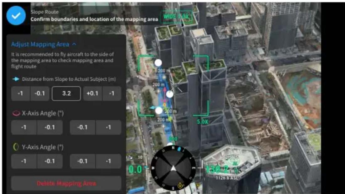
Adjust Flight Route Parameters
After the flight route is generated, tap on the Route Viewer to adjust the route parameters. Refer to the Collecting Aerial Photogrammetry Data section for more information about route parameters.
Tap Adjust Mapping Area to readjust the mapping area, if necessary.
Geometric Route
Geometric Route is used to collect photogrammetry data for multiple spatial surfaces, which is mainly used for modeling and inspection of building facades.
Set the Bottom Base Shape
-
Select the shape type of the geometry base on the left side of the map view.
-
Tap on the map to draw the base shape of the geometry.
-
Tap √ to confirm the bottom base of the mapping area.

- It is recommended to fly the aircraft to the target building and mark its boundary points. Then, enter the map view to draw the boundary points of
the mapping area's base. The points will automatically snap to the target points, making the drawing quicker and more accurate.

- Make sure there is enough space when aircraft is performing tasks. Avoid performing tasks in narrow spaces between buildings or in areas with many trees.
- The mapping surface should be non-reflective and have rich texture. Avoid mapping glass walls.
• Make sure RTK is connected during the entire process of planning and performing Geometric Route. Otherwise, the function cannot be used.
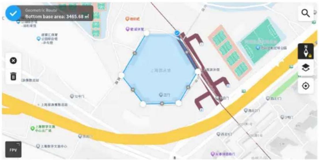
-
In the camera view, fly the aircraft to the required bottom and top base of the AR measured object. Press C1 button on the remote controller to record the altitude of the bottom base and C2 to record the altitude of the top base.
-
Tap √ to confirm the mapping aea.
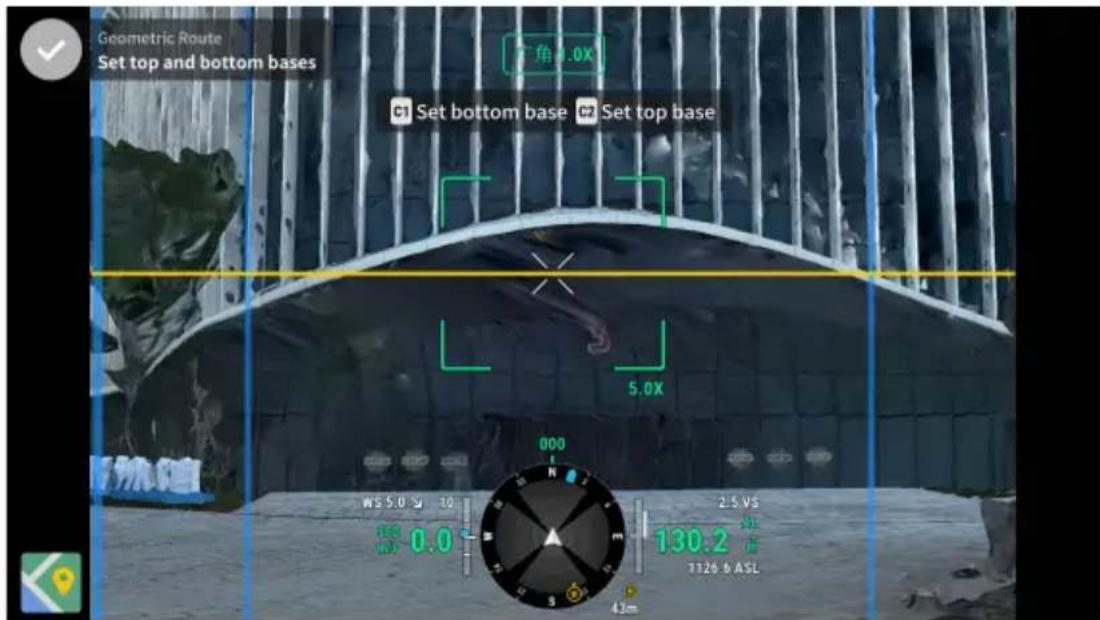
Adjust Flight Route Parameters
After the flight route is generated, tap on the Route Viewer to adjust the route parameters. Refer to the Collecting Aerial Photogrammetry Data section for more information about route parameters.
Tap Adjust Mapping Area to readjust the mapping area, if necessary.
Smart 3D Capture
Smart 3D Capture uses a rough model of the subject to generate three-dimensional flight routes for precise photography. This allows for close-range data collection near the surface of the subject. It is mainly used for modeling and inspecting complex building facades, detailed ancient architecture, and geological disaster scenarios.

Click the link below or scan the QR code to watch the tutorial video before first time use.
https://enterprise.dji.com/matrice-4-series/video
Collecting Aerial Photogrammetry Data
The following takes the Ortho Collection in the Area Route as an example for specific operation instructions.

- Before collecting aerial photogrammetry data, enter the aircraft settings to enable RTK, and ensure that RTK is connected and in FIX state.
- On the homepage of DJI Pilot 2, tap Flight Route > Create a Route > to create an Area Route. Tap on the map view, and drag the boundary point to adjust the range of the mapping area. Tap in the middle of the boundary point to add a boundary point, and adjust the longitude and latitude of the point in the parameter settings on the right. Tap to delete the current selected boundary point, and tap to delete all boundary points.
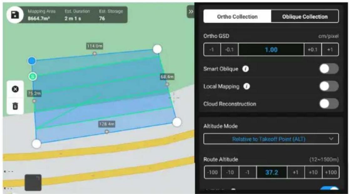
- Select the aircraft model, the camera model, and the lens, then set the following flight route parameters in sequence:
a. Set the task name and select Ortho Collection.
b. Set the altitude mode (ASL/ALT), flight route altitude, flight route speed, course angle, actions upon completion, etc., and enable elevation optimization.
c. In Advanced Settings, set the side overlap ratio, frontal overlap ratio, margin, photo mode, and customize camera angle.
-
Tap ☐ to save the task and tap ⓣ to upload and execute the flight task.
-
Power off the aircraft after the task is completed. Remove the microSD card from the aircraft, and connect it to the computer to check the taken photos and the generated files.

- When using Area Route and Linear Route, the default camera focus mode is MF infinity, and the distortion correction is disabled.
- During an orthophoto operation, it is recommended to adjust the flight route speed to the maximum value and enable elevation optimization.
Route Parameters
| Specifications Description | |
| Ortho GSD Ortho GSD is the ground sampling distance of the ortho-photos taken on the first route, i.e., the distance between two consecutive pixel centers measured on the ground. The larger the Ortho GSD value, the lower the resolution of the orthophotos. The flight route altitude will be changed accordingly when changing the Ortho GSD value. | |
| Altitude Mode The starting plane of the flight route altitude. | • Relative to Takeoff Point (ALT): the altitude of the aircraft relative to the takeoff point. It is recommended to use this option for aerial mapping operations. Then, Target Surface to Takeoff Point will appear. Target Surface to Takeoff Point = the altitude of the target surface - the altitude of the take-off point.• ASL (EGM96): the altitude of the aircraft relative to the EGM96 geoid. Flight Route to Target Surface will appear. Flight Route to Target Surface = the altitude of the flight route - the altitude of the target surface.• AGL: Altitude above Ground Level, which is the altitude of the aircraft relative to the ground below. Terrain Follow Altitude will appear. |
| Flight Route Altitude | The altitude of the flight route in a flight task. Different altitude modes have different starting planes for the flight route altitude. The Ortho GSD value will be changed accordingly when changing the flight route altitude. |
| Safe Takeoff Altitude | After taking off, the aircraft will fly up to the safe takeoff altitude (relative to the takeoff point), then fly to the start point of the flight route. Safe Takeoff Altitude is effective only when the aircraft executes a flight task before takeoff. If the aircraft starts to execute a flight task after takeoff, the safe takeoff altitude will not take effect. |
Specifications Description
Speed The operating speed of the aircraft after entering the
flight route. This speed is related to the frontal overlap ratio.
Course Angle The route angle can be adjusted, and the starting and
ending positions of the route will be adjusted accordingly. Note: the estimated time of the task varies for different course angles. By adjusting the course angle, the task with the shortest estimated time can be planned to improve the operation efficiency.
Elevation Optimization When enabled, the aircraft will fly to the center of the
mapping area to collect a set of oblique images to optimize the elevation accuracy. It is recommended to enable this option for orthophoto operation, which requires high elevation accuracy.

This feature is not supported for Oblique Collection.
Upon Completion The action performed by the aircraft after completing the
operation. The default selection is Return to Home.
Side Overlap Ratio/Frontal
Overlap Ratio
Side overlap ratio is the overlap ratio of two pictures taken on two parallel paths. Frontal overlap ratio is the overlap ratio of two pictures captured consecutively in the same heading along the flight path. The overlap ratio is one of the key factors affecting the success of later model reconstruction. The default side overlap ratio is 70%, and the default frontal overlap ratio is 80%, which is suitable for most scenarios. If the mapping area is flat and has no undulations, the overlap ratio can be appropriately reduced to improve operational efficiency. If the mapping area has large fluctuations, it is recommended to increase the overlap ratio to ensure the reconstruction effect.

When using Oblique Collection, two more settings will be available: Side Overlap Ratio (Oblique) and Frontal Overlap Ratio (Oblique). The overlap ratio of oblique photos can be lower than that of orthophotos.
| Specifications Description | |
| Margin The distance of the flight area beyond the mapping area. | |
| The purpose of setting the margin is to ensure the edge accuracy of the mapping area by capturing images outside the mapping area. | |
| Smart Oblique does not support setting margin, it will automatically expand the margin according to the range of the mapping area and the gimbal pitch. | |
| Photo Mode The camera's photo mode. The default selection is Timed Interval Shot. | |
| Custom Camera Angle Once enabled, users can customize the aircraft yaw angle and the gimbal pitch angle. Only the Ortho Collection in the Area Route supports customizing the camera angle. | |
| Route Start Point The starting point of the route can be customized in the optional points of the map view. | |
| Takeoff Speed | After the aircraft takes off and reaches the flight route altitude, the flight speed before entering the flight route. This speed is not the vertical take-off speed of the aircraft. It is recommended to set it to the maximum to improve operational efficiency. |
Other flight routes or functions also support the following specifications:
Specifications Description
Gimbal Pitch (Oblique) Adjusts the camera pitch angle when capturing oblique photos. The default angle is -45° . When the altitude difference of the buildings in the mapping area increases, it is recommended to increase the angle to capture more images of the upper floors of the buildings. When the buildings in the mapping area are dense, it is recommended to appropriately reduce the angle to capture more images between buildings.

When capturing images with Smart Oblique, the option is Gimbal Angle, and the default angle is 45° .
| Specifications Description | |
| Oblique GSD Oblique GSD is the ground sampling distance of the oblique photos captured by the remaining four routes, i.e., the distance between two consecutive pixel centers measured on the ground. The larger the Oblique GSD value, the lower the resolution of the oblique photos. The Oblique GSD value will be changed accordingly when changing the flight route altitude. | |
| Single Route If the Single Route is enabled, a route in the center of the mapping area will be generated. This function is suitable for scenes where only the center of the mapping area needs to be photographed, such as an oil pipeline inspection. | |
| Extension Length Plan the range of the flight band by adjusting the distance that the route expands from the center to the left and right sides. After enabling Equal Left/Right Extensions, the range of the flight band remains symmetrical compared to the center of the route. | |
| Flight Band Cutting Distance Adjusting the cutting distance of the flight band can divide the band area into several small areas for operation. The communication range of the aircraft should be mainly considered for the division range, ensuring that the aircraft will not lose control in a small area. | |
| Include Center Line If enabled, flight routes are generated outwards along the center line. This route will ensure that the center line of the band-shaped mapping area is included. | |
| Boundary Optimization | Add new flight routes outside the current planning flight area to take more photos of the edge of the mapping area. Turn on for objects that mainly capture edge areas, such as river channels. |
| Flight Route Direction The slope route can be executed vertically or horizontally. It is recommended to select the orientation based on the surrounding environment of the target. | |
| Rotation Angle Rotation angle of flight routes relative to geometric structure. Adjust Route Coverage Rate and Rotation Angle to realize mapping for specific face. | |
| Route Coverage Rate Coverage rate of flight routes on lateral faces of geometric structure. Adjust Route Coverage Rate and Rotation Angle to realize mapping for specific face. | |
Data Storage
Photo File
Refer to this list to check the descriptions for the photo file field.
| Field Field Description | |
| ModifyDate Time photo was modified | |
| CreateDate Time photo was created | |
| Make Manufacturer | |
| Model Product model | |
| Format Photo format | |
| Version XMP version | |
| ImageSource Camera type | |
| GpsStatus GPS status | |
| AltitudeType Elevation type | |
| GpsLatitude GPS latitude when photo was taken | |
| GpsLongitude GPS longitude when photo was taken | |
| AbsoluteAltitude Absolute altitude (geodetic altitude) when photo was taken | |
| RelativeAltitude | Relative altitude (relative to the altitude of takeoff point) when photo was taken |
| GimbalRollDegree Gimbal roll angle when photo was taken (NED coordinate system, the rotation order is ZYX) | |
| GimbalYawDegree | Gimbal yaw angle when photo was taken (NED coordinate system, the rotation order is ZYX) |
| GimbalPitchDegree | Gimbal pitch angle when photo was taken (NED coordinate system, the rotation order is ZYX) |
| FlightRollDegree | Aircraft roll angle when photo was taken (NED coordinate system, the rotation order is ZYX) |
| FlightYawDegree Aircraft yaw angle when photo was taken (NED coordinate system, the rotation order is ZYX) | |
| FlightPitchDegree | Aircraft pitch angle when photo was taken (NED coordinate system, the rotation order is ZYX) |
| FlightXSpeed | Flight speed in the north direction when photo was taken |
| FlightYSpeed | Flight speed in the east direction when photo was taken |
| FlightZSpeed | Flight speed in the elevation direction when photo was taken |
| CamReverse Whether the camera is upside down or not | |
| GimbalReverse Whether the gimbal is upside down or not | |
| SelfData Customized data | |
| RtkFlag RTK status: | 0 - Failed to position16 - Single point positioning (meter-level accuracy)32~49 - Floating point solution positioning (decimeter-level to meter-level accuracy)50 - Fixed solution positioning (centimeter-level accuracy) |
| RtkStdLon RTK positioning standard longitude deviation | |
| RtkStdLat RTK positioning standard latitude deviation | |
| RtkStdHgt RTK positioning standard elevation deviation | |
| RtkDiffAge RTK difference age (correction age) | |
| NTRIPMountPoint Mount point of Network RTK | |
| NTRIPPort Port of Network RTK | |
| NTRIPHost IP address or domain name of Network RTK | |
| SurveyingMode Whether the photo is suitable for mapping operation or not: | 0 - Not recommended, as the accuracy cannot be guaranteed1 - Recommended as the accuracy can be guaranteed |
| DewarpFlag Whether the camera parameters have been dewarped or not: | 0 - Not dewarped1 - Dewarped |
| DewarpData Camera parameters for dewarping (the calibration file must be imported and calibrated in DJI Terra for the data to be generated): | Parameter sequence - fx, fy, cx, cy, k1, k2, p1, p2, k3fx, fy - Calibrated focal length (unit: pixel)cx, cy - Calibrated optical center position (unit: pixel, origin point: photo center)k1, k2, p1, p2, k3 - Radial and tangential distortion parameters |
| CalibratedFocalLength Designed focal length of lens, unit: pixels | |
| CalibratedOpticalCenterX X coordinate of the designed optical center position,unit: pixels | |
| CalibratedOpticalCenterY Y coordinate of the designed optical center position,unit: pixels | |
| UTCAtExposure UTC when the camera is exposed. | |
| ShutterType Shutter type | |
| ShutterCount Shutter count used | |
| CameraSerialNumber Camera SN | |
| LensSerialNumber Lens serial number | |
| DroneModel Aircraft model | |
| DroneSerialNumber Aircraft serial number | |
| ProductName Product name | |
| SensorTemperature Sensor temperature | |
| SensorFPS Sensor FPS | |
| WhiteBalanceCCT White balance correlated color temperature | |
| LensPosition Lens position | |
| LensInfinitePosition | Lens infinite position |
| LensTemperature Lens temperature | |
| DewarpDataK6 | Camera parameters for dewarping:Parameter sequence - fx, fy, cx, cy, k1, k2, p1, p2, k3,k4, k5, k6fx, fy - Calibrated focal length (unit: pixel)cx, cy - Calibrated optical center position (unit: pixel,origin point: photo center)k1, k2, p1, p2, k3, k4, k5, k6 - Radial and tangentialdistortion parameters |
| LRFTargetDistance | Straight-line distance to Laser Rangefinder target point |
| LRFTargetLon Longitude of Laser Rangefinder target point | |
| LRFTargetLat | Latitude of Laser Rangefinder target point |
| LRFTargetAlt | Relative altitude of Laser Rangefinder target pointabove takeoff point |
| LRFTargetAbsAlt | Absolute altitude (ellipsoidal altitude) of Laser Rangefinder target point |
Image Log File
Open an image log file with the extension .MRK to view the data below.
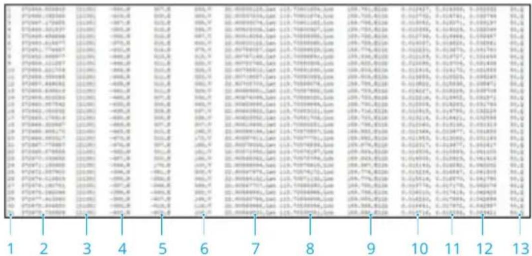
-
Photo series number: the series number of the image log file stored in this folder.
-
GPS TOW: when the photo was taken expressed in GPS TOW.
-
GPS Week: when the photo was taken expressed in GPS week.
-
Compensation value in the north direction: unit is mm and the northern direction is represented by a positive value.
-
Compensation value in the east direction: unit is mm and the eastern direction is represented by a positive value.
-
Compensation value in the elevation direction: unit is mm and the downward direction is represented by a positive value.
-
Longitude after compensation.
-
Latitude after compensation.
-
Ellipsoid height.
-
Positioning standard deviation in the north direction.
-
Positioning standard deviation in the east direction.
-
Positioning standard deviation in the elevation direction.
-
Positioning status.
GNSS Observation File
The GNSS observation file with the extension .rtk contains the satellite observation data received by the positioning module during the flight. The data is stored in the camera system in RTCM3.2 format at a frequency of 5 Hz.
8 Appendix
8.1 Specifications
Visit the following website for specifications.
https://enterprise.dji.com/matrice-4-series/specs
8.2 Firmware Update
Using DJI Pilot 2
Aircraft and Remote Controller Firmware Update
- Power on the aircraft and remote controller. Ensure the aircraft is linked to the remote controller, and the remote controller is connected to the internet.
- Run DJI Pilot 2. A prompt will appear on the homepage if new firmware is available. Tap to enter the Firmware Update view.
- Tap Update All, and DJI Pilot 2 will download the firmware and update the aircraft and remote controller.
- The aircraft and remote controller will automatically restart after the firmware update is complete.

- The devices installed on the aircraft will be updated to the latest firmware version.
Offline Firmware Update
An offline firmware package can be downloaded from the DJI official website to an external storage device such as a microSD card or U disk. Run DJI Pilot 2, tap HMS, and then Firmware Update > Offline Update to select the firmware package of the remote controller, aircraft, or payload from the external storage device and tap Update All to update.
Using DJI Assistant 2 (Enterprise Series)
Aircraft and Remote Controller Firmware Update
-
Connect the aircraft or remote controller to a computer separately, as the DJI Assistant 2 does not support updating multiple DJI devices at the same time.
-
Make sure the computer is connected to the internet and the DJI device is powered on.
- Launch DJI Assistant 2 and log in with a DJI account.
- Tap the firmware update on the left side of the main interface.
- Select the firmware version and click to update. The firmware will be downloaded and updated automatically.
- When the "Update successful" prompt appears, the update is completed, and the DJI device will restart automatically.
Notices

- Make sure the aircraft and remote controller are fully charged before updating the firmware.
- DO NOT remove accessories or turn off the devices during the update process.
- The battery firmware is included in the aircraft firmware. Be sure to update all batteries.
- During the update process, it is normal for the gimbal to go limp, the aircraft status indicators to blink, and the aircraft to reboot. Wait patiently for the update to complete.
- Make sure to keep the aircraft away from people and animals during a firmware update, system calibration, or parameter configuration.
- For safety, make sure you are using the latest firmware version.
• After the firmware update is completed, the remote controller and the aircraft may become disconnected. Reconnect the devices if necessary.
Visit the following link and refer to the Release Notes for firmware update information:
https://enterprise.dji.com/matrice-4-series/downloads
8.3 Flight Data
Flight data is automatically recorded to the internal storage of the aircraft. You can connect the aircraft to a computer via the USB port and export this data via DJI Assistant 2 or DJI Pilot 2 app.
8.4 Using Enhanced Transmission
Enhanced Transmission integrates OcuSync video transmission technology with 4G networks. If the OcuSync video transmission is obstructed, experiencing interference, or used over long distances, 4G connectivity allows you to maintain aircraft control.
The installation requirements are as shown below:
- The aircraft needs to be installed with a DJI Cellular Dongle 2. Both the dongle and nano-SIM card need to be purchased separately.
- The remote controller can be equipped with a DJI Cellular Dongle 2 or can be connected to a Wi-Fi hotspot to use Enhanced Transmission.
Enhanced Transmission will consume data. If the transmission completely switches to a 4G network, a 30-minute flight consumes about 1 GB of data on the aircraft and the remote controller, respectively. This value is for reference only. Refer to the actual data usage.

- Enhanced Transmission is only supported in some countries and regions.
- The DJI Cellular Dongle 2 and its related service are only available in some countries and regions. Comply with local laws and regulations and DJI Cellular Dongle 2 Terms of Service.
Inserting the nano-SIM Card
Open the SIM card slot cover on the dongle, insert the nano-SIM card into the slot in the same direction as shown in the figure, and close the cover.
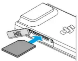

- It is strongly recommended to purchase a nano-SIM card which supports a 4G network from official channels of the local mobile network operator.
- DO NOT use an IoT SIM card, otherwise the video transmission quality will be seriously compromised.
-
DO NOT use a SIM card provided by the virtual mobile network operator, otherwise it may lead to an inability to connect to the Internet.
-
DO NOT cut the SIM card by yourself, otherwise the SIM card may be damaged, or the rough edges and corners may cause the SIM card to be unable to be inserted or removed properly.
- If the SIM card is set with a password (PIN code), make sure to insert the SIM card into the smartphone and cancel the PIN code setting, otherwise it will fail to connect to the Internet.

- Open the cover and push the nano-SIM card to partially eject it.
Installing the DJI Cellular Dongle 2
- Install the DJI Cellular Dongle 2 on to the aircraft.
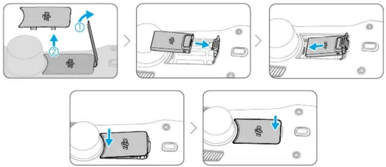
- Install the DJI Cellular Dongle 2 to the remote controller.
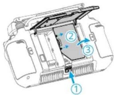

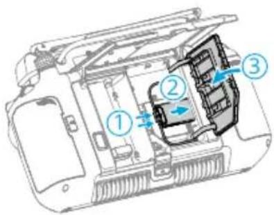

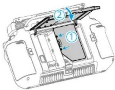
- Check the icon in the upper right corner of the system desktop. If the 4G logo appears, it means that the enhanced transmission is available.

• Gently remove the DJI Cellular Dongle 2 from the aircraft as shown if needed. DO NOT pull the antennas by force. Otherwise, the antennas may be damaged.
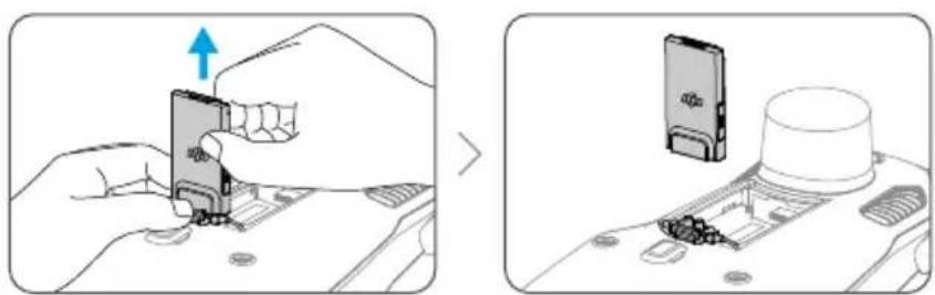
Using Enhanced Transmission
After the aircraft and the remote controller are connected by a 4G network, Enhanced Transmission can be enabled in the app.
- Go to the camera view, then tap the video transmission signal icon to enable or disable Enhanced Transmission in the pop-up box.
- Go to the camera view, tap ... > HD , and enable or disable Enhanced Transmission.

- Pay close attention to the video transmission signal strength after enabling Enhanced Transmission. Fly with caution. Tap the video transmission signal icon to view the current OcuSync video transmission and 4G video transmission signal strength in the pop-up box.
Security Strategy
Based on safe flight considerations, Enhanced Transmission can only be enabled when the OcuSync video transmission is in effect. If the OcuSync link is disconnected during flight, it is not possible to disable Enhanced Transmission.
In a 4G-only transmission scenario, restarting the remote controller or DJI Pilot 2 will result in failsafe RTH. The 4G video transmission cannot be restored before the OcuSync link is reconnected.
In the 4G-only transmission scenario, a takeoff countdown will start after the aircraft lands. If the aircraft does not take off before the countdown ends, it will not be allowed to take off until the OcuSync link is restored.
Remote Controller Usage Notes
If using the 4G network via the DJI Cellular Dongle 2, make sure to install the DJI Cellular Dongle 2 correctly, and turn off the Wi-Fi of the remote controller while using Enhanced Transmission to reduce interference.
If using the 4G network by connecting the remote controller to a mobile device Wi-Fi hotspot, make sure to set the mobile device hotspot frequency band to 2.4 GHz and the network mode to 4G for a better video transmission experience. It is not recommended to answer incoming phone calls with the same smartphone or connecting multiple devices to the same hotspot.
4G Network Requirements
The 4G network transmission speed is determined by the 4G signal strength of the aircraft and the remote controller at the current position and the network congestion level of the corresponding base station. The actual transmission experience is closely related to the local 4G network signal conditions. The 4G network signal conditions include both sides of the aircraft and the remote controller with various speeds. If the network signal of either the aircraft or remote controller is weak, has no signal, or is busy, the experience of 4G transmission may drop and lead to the video transmission freezing, a delayed response of the controls, loss of video transmission, or loss of controls.
Therefore, when using Enhanced Transmission:
- Make sure to use the remote controller and aircraft in locations where the 4G signal is close to full for a better transmission experience.
- If the OcuSync signal is disconnected, the video transmission may lag and stutter when the aircraft relies fully on a 4G signal. Fly with caution.
- When the OcuSync signal is poor or disconnected, make sure to maintain an appropriate altitude during the flight. In open areas, try to keep the flight altitude below 120 meters for a better 4G signal.
- For flight in the city with tall buildings, make sure to set a suitable RTH altitude (higher than the tallest building).
- When the app prompts that the 4G signal is weak, fly with caution.
8.5 Post-Flight Checklist
- Make sure to perform a visual inspection so that the aircraft, remote controller, gimbal camera, Intelligent Flight Battery, and propellers are in good condition. Contact DJI support if any damage is noticed.
- Make sure that the camera lens and vision system sensors are clean.
- Make sure to store aircraft correctly before transporting it.
8.6 Maintenance Instructions
To avoid serious injury to children and animals, observe the following rules:
- Small parts, such as cables and straps, are dangerous if swallowed. Keep all parts out of reach of children and animals.
- Store the Intelligent Flight Battery and remote controller in a cool, dry place away from direct sunlight to ensure the built-in LiPo battery does NOT overheat. Recommended storage temperature: between 22° and 28° C ( 71° and 82° F) for storage periods of more than three months. Never store in environments outside the temperature range of 14° to 113° F (- 10° to 45° C).
- DO NOT allow the camera to come into contact with or become immersed in water or other liquids. If it gets wet, wipe dry with a soft, absorbent cloth. Turning on an aircraft that has fallen in water may cause permanent component damage. DO NOT use substances containing alcohol, benzene, thinners, or other flammable substances to clean or maintain the camera. DO NOT store the camera in humid or dusty areas.
- DO NOT connect this product to any USB interface older than version 3.0.
- Check every aircraft part after any crash or serious impact. If there are any problems or questions, contact a DJI authorized dealer.
- Regularly check the Battery Level Indicators to see the current battery level and overall battery life. The battery is rated for 200 cycles. It is not recommended to continue use afterward.
- Make sure to transport the aircraft with the arms folded when powered off.
- Make sure to transport the remote controller with antennas folded when powered off.
- The battery will enter sleep mode during long-term storage. Charge the battery to exit from sleep mode.
- Store the aircraft, remote controller, battery, and charger in a dry environment. It is recommended to store and transport the product in an environment with an ambient temperature of 15° to 25° C and a humidity of about 40%.
- Remove the battery before servicing the aircraft (e.g., cleaning or attaching and detaching the propellers). Make sure that the aircraft and the propellers are clean by removing any dirt or dust with a soft cloth. Do not clean the aircraft with a wet cloth or use a cleanser that contains alcohol. Liquids can penetrate the aircraft housing, which can cause a short circuit and destroy the electronics.
- Make sure to turn off the battery to replace or to check the propellers.
8.7 Troubleshooting Procedures
- Why can the battery not be used before the first flight?
The battery must be activated by charging before using it for the first time.
- How to solve the gimbal drift issue during flight?
Calibrate IMU and compass in DJI Pilot 2. If the problem persists, contact DJI Support.
- No function
Check if the Intelligent Flight battery and the remote controller are activated by charging. If the problems persist, contact DJI Support.
- Power-on and start-up problems
Check if the battery has power. If yes, contact DJI Support if it cannot be started normally.
- SW update issues
Follow the instructions in the user manual to update the firmware. If the firmware update fails, restart all the devices and try again. If the problem persists, contact DJI Support.
- Procedures to reset to factory default or last known working configuration
Use the DJI Pilot 2 app to reset to factory default.
- Shutdown and power-off problems
Contact DJI Support.
- How to detect careless handling or storage in unsafe conditions
Contact DJI Support.
8.8 Risks and Warnings
When the aircraft detects a risk after powering on, there will be a warning prompt on DJI Pilot 2. Pay attention to the list of situations below.
- If the location is not suitable for takeoff.
- If an obstacle is detected during flight.
- If the location is not suitable for landing.
- If the compass and IMU experience interference and need to be calibrated.
- Follow the on-screen instructions when prompted.
8.9 Disposal

Observe the local regulations related to electronic devices when disposing of the aircraft and remote controller.
Battery Disposal
Dispose of the batteries in specific recycling containers only after a complete discharge. DO NOT dispose of the batteries in regular trash containers. Strictly follow the local regulations regarding the disposal and recycling of batteries.
Dispose of a battery immediately if it cannot be powered on after over-discharging.
If the power on/off button on the Intelligent Flight Battery is disabled and the battery cannot be fully discharged, contact a professional battery disposal/recycling agency for further assistance.
8.10 C2 Certification
DJI Matrice 4T / DJI Matrice 4E is comply with C2 certification, there are some requirements and restrictions when using DJI Matrice 4T / DJI Matrice 4E in European Economic Area (EEA, i.e. EU plus Norway, Iceland and Liechtenstein). DJI Matrice 4T / DJI Matrice 4E and its similar products are distinguished by model name.
| UAS Class C2 | |
| Sound Power Level 85 dB | |
| Maximum Propeller Speed 6130 RPM |
MTOM Statement
The MTOM of DJI Matrice 4T / DJI Matrice 4E (Model M4T/M4E) is 1430 g to comply with C2 requirement.
You must follow the instructions below to comply with the MTOM requirements for each model:
- Make sure that when installing any external devices, the total weight of the aircraft does not exceed the maximum takeoff weight (1430 g). In addition, the external devices must be installed in a location that ensures the center of gravity is maintained within the range of the aircraft's top shell to keep the aircraft stable, and that the vision systems, infrared sensing systems, and auxiliary lights are not blocked. Make sure that the MTOM is not larger than 1430 g for any flight.
- DO NOT use any non-qualified replacement parts, such as intelligent flight batteries or propellers, etc.
• DO NOT retrofit the aircraft.

- The prompt "Low Battery RTH" will not appear if the horizontal distance between the pilot and the aircraft is closer than 5 m.
List of Items, including qualified accessories
| Item Model Number Dimensions Weight | |||
| Propellers 1154F | 27.4×13.7 cm (diameter×thread pitch) | 13.7 g (each piece) | |
| Battery BPX345-6741-14.76 | 145.47×60.6×46.3 cm 400 g | ||
| DJI AL1 SpotLight [1] | AL-1 | 9.5×16.4×3.0 cm (with bracket) | 99 g (with bracket) |
| DJI AS1 Speaker [1] | AS-1 | 7.3×7.0×5.2 cm (with bracket)7.3×7.0×4.7 cm (without bracket) | 92.5 g (with bracket)90 g (without bracket) |
| microSD Card N/A N/A Approx. 0.3 g | |||
| DJI Cellular Dongle 2 [1] | IG831T 4.35×2.3×0.7 cm 11.5 g | ||
| DJI Matrice 4 Series Propeller Guard [1] | N/A 75.5×64.0×15.0 cm 165 g | ||
[1] Not included in the original package. Please be careful not to exceed MTOM.
List of Spare and Replacement Parts
| Item Model Number Dimensions Weight | |||
| Propellers 1154F | 27.4×13.7 cm (diameter×thread pitch) | 13.7 g (each piece) | |
| Battery BPX345-6741-14.76 | 145.47×60.6×46.3 cm 400 g | ||
| DJI AL1 SpotLight [1] | AL-1 | 9.5×16.4×3.0 cm (with bracket) | 99 g (with bracket) |
| DJI AS1 Speaker [1] | AS-1 | 7.3×7.0×5.2 cm (with bracket)7.3×7.0×4.7 cm (without bracket) | 92.5 g (with bracket)90 g (without bracket) |
| microSD Card N/A N/A Approx. 0.3 g | |||
| DJI Cellular Dongle 2 [1] | IG831T 4.35×2.3×0.7 cm 11.5 g | ||
| DJI Matrice 4 Series Propeller Guard [1] | N/A 75.5×64.0×15.0 cm 165 g | ||
[1] Not included in the original package. Please be careful not to exceed MTOM.
Remote Controller Warnings
The remote controller indicator will glow red after disconnecting from the aircraft. DJI Pilot 2 will issue a warning prompt after disconnecting from the aircraft. The remote controller will beep and power off automatically after disconnecting from aircraft and with no operation for a long time.

- Avoid interference between the remote controller and other wireless equipment. Make sure to turn off the Wi-Fi on nearby mobile devices. Land the aircraft as soon as possible if there is interference.
- Users are responsible for correctly adjusting the display brightness when using the monitor in direct sunlight during flight operation.
- Release the control sticks or press the flight pause button if an unexpected operation occurs.
Direct Remote ID
- Transport Method: Wi-Fi Beacon.
- Method of uploading the UAS Operator Registration Number to the aircraft: Enter DJI Pilot 2 > GEO Zone Map > UAS Remote Identification, and then upload UAS Operator Registration Number.
- According to applicable rules, operators shall provide the correct registration number to broadcast in flight. Please make sure you understand and comply with the rules.
GEO Awareness
GEO Awareness contains the features listed below.
UGZ (Unmanned Geographical Zone) Data update: You can update the FlySafe data by using the data update feature automatically or storing the data in the aircraft manually.
- Method 1: Run DJI Pilot 2, tap GEO Zone Map > FlySafe Database, select Auto Update from Data Source to update the FlySafe data automatically.
- Method 2: Check the website of your national aviation authority regularly and obtain the latest UGZ data to import to your aircraft. Run DJI Pilot 2, tap GEO Zone Map > FlySafe Database, select Import Local File from Data Source, and then follow the on-screen instructions to store and import the UGZ data manually.

- A prompt will appear in the app when the import completes successfully. If the import fails due to improper data format, follow the on-screen prompt and retry.

- Before takeoff, users must download the latest GEO Zone data from the official aviation regulation website of the country or region where the aircraft is being used. It is the responsibility of the user to make sure that the GEO zone data is the latest version and that it is applied to every flight.
GEO Awareness Map Drawing: After the latest UGZ data is updated, a flight map with a restricted zone will be displayed in the DJI Pilot 2 app. Name, effective time, height limit, etc., can be viewed by tapping the area.
When GNSS signal is weak, Geo-awareness function will be degraded and the remote controller will provide a prompt. Fly with caution.
AGL (Above Ground Level) Statement
The vertical part of Geo-Awareness may use the AMSL altitude or the AGL height. The choice between these two references is specified individually for each UGZ. Neither AMSL altitude nor the AGL height is supported by DJI Matrice 4 Series. The height H appears in the DJI Pilot 2 app camera view, which is the height from the aircraft takeoff point to the aircraft. The height above the takeoff point may be used as an approximation but may differ more or less from the given altitude/height for a specific UGZ. The remote pilot remains responsible for not breaching the vertical limits of the UGZ.
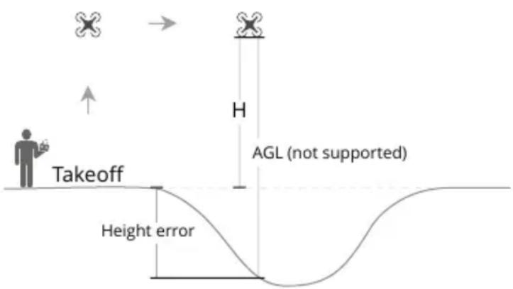
GEO Zones
Restricted Zones
Appear red in the DJI app. You will be prompted with a warning, and flight is prevented. UA cannot fly or take off in these zones. Restricted Zones may be unlocked, to unlock contact flysafe@dji.com or go to Unlock A Zone at dji.com/flysafe.
![graph TD A["Restricted Zones"] --> B{Receiving a warning} B -->|20 m| C["Limit maximum speed"] B -->|100 m| D["When approaching: 1. Receiving a warning\n2. Can not fly in\n3. You can apply on the DJI official website after manual approval"] A --> E{When taking off: 1. Receiving a warning\n2. Can not…](/content/2026/08/1627030/images/f1d6a71193ac67d324f60089e635f8a029b011bf33f0812c71ad185099f650b2.jpg)
Authorization Zones
Appear blue in the DJI app. You will be prompted with a warning, and flight is limited by default. UA cannot fly or take off in these zones unless authorized. Authorization Zones may be unlocked by authorized users using a DJI verified account.
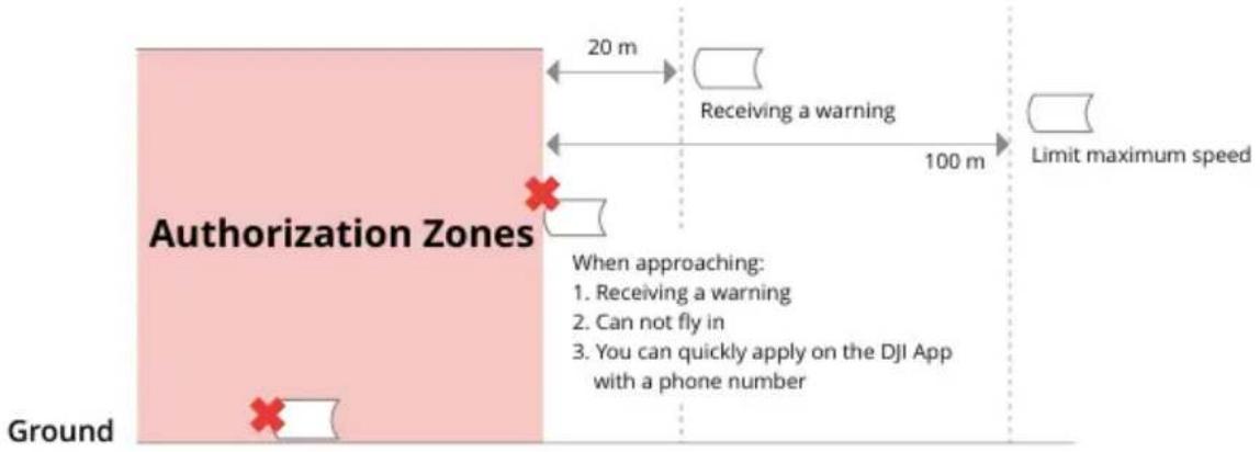
Altitude Zones
Altitude zones are zones with a limited altitude and appear in gray on the map. When approaching, you will receive a warning in the DJI app.
![graph LR A["Altitude Zones"] -->|20 m| B["Receiving a warning"] B -->|100 m| C["Limit maximum speed"] D["Limited altitude"] -->|10 m| E["Limit maximum speed"] F["Ground"] --> G["1. UA can take off and fly into these zones in specific height with a warning message\n2. You can apply for permission on…](/content/2026/08/1627030/images/83ef8c154bc7e95dbbed09ffaa096e19718191c7f7fedba28c7629a7c116f07a.jpg)
Enhanced Warning Zones
A warning message will appear when the drone reaches the edge of the zone.
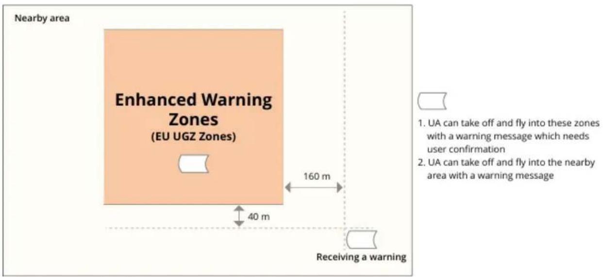
Warning Zones
A warning message will prompt you when the drone reaches the edge of the zone.
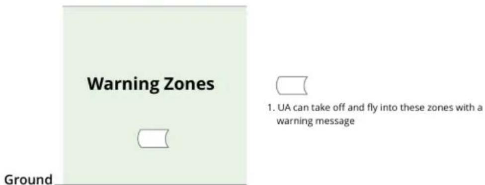

- When the aircraft and DJI Pilot 2 app cannot obtain a GPS signal, the GEO awareness function will be inoperative. Interference of the aircraft antenna or disabling the GPS authorization in DJI Pilot 2 will cause the GPS signal fails to be obtained.
EASA Notice
Make sure to read the Drone Information Notices document included in the package before use.
Visit the link below for more EASA notice information on traceability.
https://www.easa.europa.eu/en/document-library/general-publications/drones-information-notices
Original Instructions
This manual is provided by SZ DJI Technology, Inc., and the content is subject to change.
Address: Lobby of T2, DJI Sky City, No. 53 Xianyuan Road, Xili Community, Xili Street, Nanshan District, Shenzhen, China, 518055.
8.11 FAR Remote ID Compliance Information
The unmanned aircraft system is equipped with a Remote ID system that meets the requirements of 14 CFR Part 89.
- The aircraft automatically initiates a pre-flight self-test (PFST) of the Remote ID system before takeoff and cannot take off if it does not pass the PFST[1]. The results of the PFST of the Remote ID system can be viewed in a DJI flight control app such as DJI Pilot 2.
- The aircraft monitors the Remote ID system functionality from pre-flight to shut down. If the Remote ID system malfunctions or has a failure, an alarm will be displayed in a DJI flight control app such as DJI Pilot 2.
- The user shall keep the DJI flight control app running in the foreground and always allow it to obtain the location information of the remote controller.
- Developers who develop third-party applications based on the DJI Mobile SDK shall obtain and display the PFST results and the failure status of the Remote ID system during operation by calling specific APIs [2].
- Developers who develop third-party platforms based on the DJI Cloud API shall obtain and display the PFST results and the failure status of the Remote ID system during operation by calling specific APIs [3].
- Developers developing payload devices based on DJI PSDK shall read and comply with the requirements in the PSDK's "Flight Safety Notification", and shall not disrupt or degrade the functionality of the Remote ID system. For "Non-RC Flight" developers, they shall send the true and accurate geographic location information of the pilot or operator obtained by appropriate technology to the Remote ID system by calling specific APIs [4] provided by the PSDK, and shall obtain and display the PFST results and the failure status of the Remote ID system during operation by calling specific APIs.
- You can visit the official website of FAA to learn more about aircraft registration and Remote ID requirements.
Footnotes
[1] The pass criterion for PFST is that the hardware and software of the Remote ID required-data source and transmitter radio in the Remote ID system are functioning properly.
[2] For detailed APIs information, please visit https://developer.dji.com/mobile-sdk/
[3] For detailed APIs information, please visit https://developer.dji.com/cloud-api/
[4] For detailed APIs information, please visit https://developer.dji.com/payload-sdk/

Contact
DJI SUPPORT
The terms HDMI, HDMI High-Definition Multimedia Interface, HDMI trade dress and the HDMI Logos are trademarks or registered trademarks of HDMI Licensing Administrator, Inc.
The content is subject to change without prior notice.
Download the latest version from

https://enterprise.dji.com/matrice-4-series/downloads
If you have any questions about this document, contact DJI by sending a message to DocSupport@dji.com.
DJI and MATRICE are trademarks of DJI.
Copyright © 2025 DJI All Rights Reserved.
- SEARCHING FOR KEYWORDS
- NAVIGATING TO A TOPIC
- PRINTING THIS DOCUMENT
- USING THIS MANUAL
- LEGEND
- READ BEFORE USE
- VIDEO TUTORIALS
- DOWNLOAD DJI ASSISTANT
- CONTENTS
- OVERVIEW
- FLIGHT SAFETY
- USING FOR THE FIRST TIME
- AIRCRAFT
- CAMERA
- GIMBAL
- INTELLIGENT FLIGHT BATTERY
- AIRCRAFT RTK
- RETURN TO HOME
- SENSING SYSTEM
- ADVANCED PILOT ASSISTANCE SYSTEMS
- DJI AIRSENSE
- EXPANSION PORT
- REMOTE CONTROLLER
- CHARGING THE BATTERY
- OPERATING THE TOUCHSCREEN
- REMOTE CONTROLLER LEDS
- REMOTE CONTROLLER ALERT
- DJI PILOT 2 APP
- FLIGHT OPERATIONS
- APPENDIX
- OPERATING THE AIRCRAFT RESPONSIBLY
- FLIGHT RESTRICTIONS
- GEO (GEOSPATIAL ENVIRONMENT ONLINE) SYSTEM
- GEO ZONES
- RESTRICTED ZONES (RED)
- SCENARIO
- AUTHORIZATION ZONES (BLUE)
- WARNING ZONES (YELLOW)
- ENHANCED WARNING ZONES (ORANGE)
- ALTITUDE ZONES (GRAY)
- BUFFER ZONE
- BUFFER ZONES FOR RESTRICTED ZONES/AUTHORIZATION ZONES
- BUFFER ZONES FOR ALTITUDE ZONES
- UNLOCKING GEO ZONES
- FLIGHT ALTITUDE AND DISTANCE LIMITS
- FLIGHT ENVIRONMENT REQUIREMENTS
- PREPARING THE REMOTE CONTROLLER
- PREPARING THE AIRCRAFT
- ACTIVATION
- BASIC FLIGHT
- PRE-FLIGHT CHECKLIST
- STARTING/STOPPING THE MOTORS
- STARTING THE MOTORS
- STOPPING THE MOTORS
- STOPPING THE MOTORS MID-FLIGHT
- CONTROLLING THE AIRCRAFT
- FLIGHT MODES
- NORMAL MODE
- SPORT MODE
- FUNCTION MODE
- AIRCRAFT STATUS INDICATOR
- FRONT LED 2. AIRCRAFT STATUS INDICATOR
- AIRCRAFT STATUS INDICATORS DESCRIPTIONS
- NORMAL STATES
- BEACON
- PROPELLERS
- NOTICE
- STORING AND EXPORTING PHOTOS AND VIDEOS
- GIMBAL ANGLE
- GIMBAL NOTICE
- INSERTING/REMOVING THE BATTERY
- CHECKING THE BATTERY LEVEL
- USING THE CHARGING HUB
- USAGE
- STATUS LED DESCRIPTIONS
- BATTERY LEVEL LEDS
- BATTERY PROTECTION MECHANISMS
- ENABLING/DISABLING RTK
- CUSTOM NETWORK RTK
- ADVANCED RTH
- TRIGGER METHOD
- THE USER ACTIVELY TRIGGERS RTH
- AIRCRAFT LOW BATTERY
- LOSS OF REMOTE CONTROLLER SIGNAL
- RTH PROCEDURE
- PAY ATTENTION IF GNSS WAS UNAVAILABLE WHEN TAKEOFF
- TERRAIN DATA
- RTH SETTINGS
- LANDING PROTECTION
- VISION ASSIST
- BUTTON COMBINATIONS
- COMBINATION OPERATION FUNCTION
- STATUS LED
- BLINKING PATTERN DESCRIPTIONS
- OPTIMAL TRANSMISSION ZONE
- LINKING THE REMOTE CONTROLLER
- METHOD 1: USING COMBINATION BUTTONS
- METHOD 2: USING APP
- HDMI SETTINGS
- HOMEPAGE
- PROFILE
- DATA AND PRIVACY
- GEO ZONE MAP
- CLOUD SERVICE
- FLIGHT ROUTE
- CAMERA VIEW
- TOP BAR
- BATTERY LEVEL INDICATOR BAR
- GNSS POSITIONING STATUS
- SIGNAL STRENGTH
- INTELLIGENT FLIGHT BATTERY LEVEL
- SETTINGS
- NAVIGATION DISPLAY
- HOME POINT AND REMOTE CONTROLLER ORIENTATIONS
- HOME POINT DISTANCE
- PINPOINT INFORMATION
- WAYPOINT INFORMATION
- RNG TARGET POINT INFORMATION
- VERTICAL OBSTACLE SENSING INFORMATION
- HORIZONTAL OBSTACLE SENSING INFORMATION
- ZOOM CAMERA VIEW
- WIDE-ANGLE CAMERA VIEW
- ZOOM FRAME
- THERMAL CAMERA VIEW
- PALETTE
- GAIN MODE
- SBS
- FFC
- LINK ZOOM
- THERMAL CAMERA ZOOM
- LASER RANGEFINDING
- PRIMARY FLIGHT DISPLAY
- ANNOTATION MANAGEMENT AND SYNCHRONIZATION
- PINPOINT
- CREATE A PINPOINT
- SELECTED PINPOINT
- LINE AND AREA ANNOTATION MANAGEMENT
- ANNOTATION SHARING
- INTELLIGENT FUNCTIONS
- POI
- FLIGHT TASKS
- WAYPOINT ROUTE
- SET WAYPOINTS
- LIVE MISSION RECORDING
- AI SPOT-CHECK
- AREA ROUTE
- SMART OBLIQUE
- TERRAIN FOLLOW
- REAL-TIME FOLLOW
- DSM FOLLOW
- IMPORT LOCAL FILE
- DOWNLOAD FROM INTERNET
- LINEAR ROUTE
- SLOPE ROUTE
- CREATE SLOPE
- ADJUST AND CONFIRM AR SLOPE
- ADJUST FLIGHT ROUTE PARAMETERS
- GEOMETRIC ROUTE
- SET THE BOTTOM BASE SHAPE
- SMART 3D CAPTURE
- COLLECTING AERIAL PHOTOGRAMMETRY DATA
- SPECIFICATIONS DESCRIPTION
- DATA STORAGE
- PHOTO FILE
- IMAGE LOG FILE
- GNSS OBSERVATION FILE
- SPECIFICATIONS
- FIRMWARE UPDATE
- USING DJI PILOT
- AIRCRAFT AND REMOTE CONTROLLER FIRMWARE UPDATE
- OFFLINE FIRMWARE UPDATE
- USING DJI ASSISTANT 2 (ENTERPRISE SERIES)
- NOTICES
- FLIGHT DATA
- USING ENHANCED TRANSMISSION
- INSERTING THE NANO-SIM CARD
- INSTALLING THE DJI CELLULAR DONGLE
- SECURITY STRATEGY
- REMOTE CONTROLLER USAGE NOTES
- G NETWORK REQUIREMENTS
- POST-FLIGHT CHECKLIST
- MAINTENANCE INSTRUCTIONS
- TROUBLESHOOTING PROCEDURES
- RISKS AND WARNINGS
- DISPOSAL
- BATTERY DISPOSAL
- C2 CERTIFICATION
- MTOM STATEMENT
- REMOTE CONTROLLER WARNINGS
- DIRECT REMOTE ID
- GEO AWARENESS
- AGL (ABOVE GROUND LEVEL) STATEMENT
- RESTRICTED ZONES
- AUTHORIZATION ZONES
- ALTITUDE ZONES
- ENHANCED WARNING ZONES
- WARNING ZONES
- EASA NOTICE
- ORIGINAL INSTRUCTIONS
- FAR REMOTE ID COMPLIANCE INFORMATION
- FOOTNOTES
Brand : DJI
Model : Matrice 4
Category : Drone