
XG-C55X - Projector SHARP - Free user manual and instructions
Find the device manual for free XG-C55X SHARP in PDF.


| Product Type | Projector |
| Brand | Sharp |
| Model | XG-C55X |
| Display Technology | DLP |
| Native Resolution | XGA (1024 x 768) |
| Brightness | 3000 ANSI Lumens |
| Contrast Ratio | 2000:1 |
| Aspect Ratio | 4:3 native |
| Lamp Life | Up to 3000 hours (normal mode) |
| Zoom Ratio | 1.2x manual zoom |
| Keystone Correction | ±20 degrees vertical |
| Inputs | VGA, S-Video, Composite, Audio |
| Dimensions (W x D x H) | 315 x 294 x 120 mm |
| Weight | 3.9 kg |
| Power Consumption | 300 W (max) |
| Power Supply | AC 100-240V, 50/60 Hz |
| Noise Level | 35 dB |
| Maintenance | Replace lamp after 3000 hours; clean air filter periodically |
| Safety | Overheat protection, automatic shutdown |
| Spare Parts | Replacement lamp (AN-C55LP), remote control, air filter |
| General Information | Designed for presentations and business meetings |
Frequently Asked Questions - XG-C55X SHARP
User questions about XG-C55X SHARP
0 question about this device. Answer the ones you know or ask your own.
Ask a new question about this device
Download the instructions for your Projector in PDF format for free! Find your manual XG-C55X - SHARP and take your electronic device back in hand. On this page are published all the documents necessary for the use of your device. XG-C55X by SHARP.
USER MANUAL XG-C55X SHARP
LCD PROJECTOR


香港電器安全規格
(國際電工委員會規格適合)
IMPORTANT
For your assistance in reporting the loss or theft of your Projector, please record the Serial Number located on the bottom of the projector and retain this information. Before recycling the packaging, please be sure that you have checked the contents of the carton thoroughly against the list of "Supplied accessories" on page 14.
Model No.: XG-C55X
Serial No.:
This equipment complies with the requirements of Directives 89/336/EEC and 73/23/EEC as amended by 93/68/EEC.
The mains lead of this product is fitted with a non-rewireable (moulded) plug incorporating a 10A fuse. Should the fuse need to be replaced, a BSI or ASTA approved BS 1362 fuse marked 🌐 or 🚗 of the same rating as above, which is also indicated on the pin face of the plug, must be used.
Always refit the fuse cover after replacing the fuse. Never use the plug without the fuse cover fitted.
In the unlikely event of the socket outlet in your home not being compatible with the plug supplied, cut off the mains plug and fit an appropriate type.
DANGER:
The fuse from the cut-off plug should be removed and the cut-off plug destroyed immediately and disposed of in a safe manner.
Under no circumstances should the cut-off plug be inserted elsewhere into a 10A socket outlet, as a serious electric shock may occur.
To fit an appropriate plug to the mains lead, follow the instructions below:
IMPORTANT:
The wires in the mains lead are coloured in accordance with the following code:
Blue: Neutral
Brown: Live
As the colours of the wires in the mains lead of this product may not correspond with the coloured markings identifying the terminals in your plug, proceed as follows:
- The wire which is coloured blue must be connected to the plug terminal which is marked N or coloured black.
- The wire which is coloured brown must be connected to the plug terminal which is marked L or coloured red.
Ensure that neither the brown nor the blue wire is connected to the earth terminal in your three-pin plug.
Before replacing the plug cover make sure that:
- If the new fitted plug contains a fuse, its value is the same as that removed from the cut-off plug.
- The cord grip is clamped over the sheath of the mains lead, and not simply over the lead wires.
IF YOU HAVE ANY DOUBT, CONSULT A QUALIFIED ELECTRICIAN.
| The supplied CD-ROM contains operation instructions in English, German, French, Swedish, Spanish, Italian, Dutch, Portuguese, Chinese (Traditional Chinese and Simplified Chinese) and Korean. Carefully read through the operation instructions before operating the projector. |
| Die mitgelieferte CD-ROM enthält Bedienungsanleitungen in Englisch, Deutsch, Französisch, Schwedisch, Spanisch, Italienisch, Niederländisch, Portugiesisch, Chinesisch (Traditionelles Chinesisch und einfaches Chinesisch) und Koreanisch. Bitte lesen Sie die Bedienungsanleitung vor der Verwendung des Projektors sorgfältig durch. |
| Le CD-ROM fourni contient les instructions de fonctionnement en anglais, allemand, français, suédois, espagnol, italien, néerlandais, portugais, chinois (chinois traditionnel et chinois simplifié) et coréen. Veuillez lire attentivement ces instructions avant de faire fonctionner le projecteur. |
| Den medföljande CD-ROM-skivan innehåller bruksanvisningar på engelska, tyska, franska, svenska, spanska, italienska, holländska, portugisiska, kinesiska (traditionell kinesiska och förenklad kinesiska) och koreanska. Läs noga igenom bruksanvisningen innan projektorn tas i bruk. |
| El CD-ROM suministrado contiene instrucciones de operación en inglés, alemán, francés, sueco, español, italiano, holandés, portugués, chino (chino tradicional y chino simplificado) y coreano. Lea cuidadosamente las instrucciones de operación antes de utilizar el proyector. |
| Il CD-ROM in dotazione contiene istruzioni per l'uso in inglese, tedesco, francese, svedese, spagnolo, italiano, olandese, portoghese, cinese (cinese tradizionale e cinese semplificato) e coreano. Leggere attentamente le istruzioni per l'uso prima di usare il proiettore. |
| De meegeleverde CD-ROM bevat handleidingen in het Engels, Duits, Frans, Zweeds, Spaans, Italiaans, Nederlands, Portugees, Chinees (Traditioneel Chinees en Vereenvoudigd Chinees) en Koreaans. Lees de handleiding zorgvuldig door voor u de projector in gebruik neemt. |
| O CD-ROM fornecido contém instruções de operação em Inglês, Alemão, Francês, Sueco, Espanhol, Italiano, Holandês, Português, Chinês, (Chinês Tradicional e Chinês Simplificado) e Coreano. Leia cuidadosamente todas as instruções de operação antes de operar o projetor. |
| 附送之CD-ROM光碟中,有用英文、德文、法文、瑞典文、西班牙文、意大利文、荷蘭文、葡萄牙文、中文(繁體中文和簡體中文)和韓國文所寫的使用説明書。在操作本投影機之前,請務必仔細閱讀整本使用説明書。 |
| 附送之CD-ROM光碟中,有用英文、德文、法文、瑞典文、西班牙文、意大利文、荷兰文、葡萄牙文、中文(繁体中文和简体中文)和韩国文所写的使用说明书。在操作本投影机之前,请务必仔细阅读整本使用说明书。 |
| 제공된 CD-ROM에는 영어, 독일어, 프랑스어, 스웨덴어, 스페인어, 이탈리아어, 네덜란드어, 포르투갈어, 중국어(번체자와 간체자), 그리고 한국어로 작성된 조작 설명서가 포함되어 있습니다. 프로젝터를 조작하기 전에 조작 지침을 상세하게 숙지하십시오. |
Introduction
ENGLISH
There are two important reasons for prompt warranty registration of your new SHARP Projector, using the REGISTRATION CARD packed with the projector.
1. WARRANTY
This is to assure that you immediately receive the full benefit of the parts, service and labor warranty applicable to your purchase.
2. CONSUMER PRODUCT SAFETY ACT
To ensure that you will promptly receive any safety notification of inspection, modification, or recall that SHARP may be required to give under the 1972 Consumer Product Safety Act, PLEASE READ CAREFULLY THE IMPORTANT "LIMITED WARRANTY" CLAUSE. [U.S.A. ONLY]
WARNING:
High brightness light source. Do not stare into the beam of light, or view directly. Be especially careful that children do not stare directly into the beam of light.

WARNING: To reduce the risk of fire or electric shock, do not expose this product to rain or moisture.
CAUTION: TO REDUCE THE RISK OF ELECTRIC SHOCK, DO NOT REMOVE COVER.
NO USER-SERVICEABLE PARTS EXCEPT LAMP UNIT. REFER SERVICING TO QUALIFIED SERVICE PERSONNEL.
The lightning flash with arrowhead symbol, within an equilateral triangle, is intended to alert the user to the presence of uninsulated “dangerous voltage” within the product’s enclosure that may be of sufficient magnitude to constitute a risk or electric shock to persons.

The exclamation point within a triangle is intended to alert the user to the presence of important operating and maintenance (servicing) instructions in the literature accompanying the product.
WARNING:
FCC Regulations state that any unauthorized changes or modifications to this equipment not expressly approved by the manufacturer could void the user's authority to operate this equipment. U.S.A. ONLY
INFORMATION
This equipment has been tested and found to comply with the limits for a Class A digital device, pursuant to Part 15 of the FCC Rules. These limits are designed to provide reasonable protection against harmful interference when the equipment is operated in a commercial environment. This equipment generates, uses, and can radiate radio frequency energy and, if not installed and used in accordance with the operation manual, may cause harmful interference to radio communications. Operation of this equipment in a residential area is likely to cause harmful interference, in which case the user will be required to correct the interference at his own expense. U.S.A. ONLY
The enclosed computer cable must be used with the device. The cable is provided to ensure that the device complies with FCC Class A verification. U.S.A. ONLY
WARNING:
This is a Class A product. In a domestic environment this product may cause radio interference in which case the user may be required to take adequate measures.
WARNING:
The cooling fan in this projector continues to run for about 90 seconds after the projector enters the standby mode. During normal operation, when putting the projector into the standby mode always use the STANDBY button on the projector or on the remote control. Ensure the cooling fan has stopped before disconnecting the power cord. DURING NORMAL OPERATION, NEVER TURN THE PROJECTOR OFF BY DISCONNECTING THE POWER CORD. FAILURE TO OBSERVE THIS WILL RESULT IN PREMATURE LAMP FAILURE.
PRODUCT DISPOSAL
This projector utilizes tin-lead solder, and a pressurized lamp containing a small amount of mercury. Disposal of these materials may be regulated due to environmental considerations. For disposal or recycling information, please contact your local authorities or, if you are located in the United States of America, the Electronic Industries Alliance: www.eiae.org.

Caution Concerning the Lamp Replacement
See "Replacing the Lamp" on page 85.

LAMP REPLACEMENT CAUTION
BEFORE REMOVING THE SCREW, DISCONNECT POWER CORD. HOT SURFACE INSIDE. ALLOW 1 HOUR TO COOL BEFORE REPLACING THE LAMP. REPLACE WITH SAME SHARP LAMP UNIT TYPE BQC-XGC55X//1 ONLY. UV RADIATION : CAN CAUSE EYE DAMAGE. TURN OFF LAMP BEFORE SERVICING. HIGH PRESSURE LAMP : RISK OF EXPLOSION. POTENTIAL HAZARD OF GLASS PARTICLES IF LAMP HAS RUPTURED. HANDLE WITH CARE. SEE OPERATION MANUAL

PRECAUTIONS A OBSERVER LORS DU REMPLACEMENT DE LA LAMPE.
DEBRANCHER LE CORDON D'ALIMENTATION AVANT DE RETIRER LES VIS. L'INTERIEUR DU BOITIER ETANT EXTREMEMENT CHAUD, ATTENDRE 1 HEURE AVANT DE PROCEDER AU REMPLACEMENT DE LA LAMPE. NE REEMPLACER QUE PAR UNE LAMPE SHARP DE TYPE BQC-XGC55X//1. RAYONS ULTRAVIOLETS : PEUVENT ENDOMMAGER LES YEUX. ETEINDRE LA LAMPE AVANT DE PROCEDER A L'ENTRETIEN. LAMPE A HAUTE PRESSION : RISQUE D'EXPLOSION. DANGER POTENTIEL DE PARTICULES DE VERRE EN CAS D'ECLATEMENT DE LA LAMPE. A MANIPULER AVEC PRECAUTION, SE REPORTER AU MODE D'EMPLOI.
This SHARP projector uses an LCD (Liquid Crystal Display) panel. This very sophisticated panel contains 786,432 pixels (× RGB) TFTs (Thin Film Transistors). As with any high technology electronic equipment such as large screen TVs, video systems and video cameras, there are certain acceptable tolerances that the equipment must conform to. This unit has some inactive pixels within acceptable tolerances which may result in inactive dots on the picture screen. This will not affect the picture quality or the life expectancy of the unit.
When Attaching the "QUICK GUIDE" Label
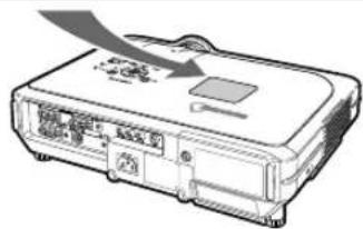
Attaching the "QUICK GUIDE" Label (supplied) on the projector will help you check the setup procedure. When you attach the "QUICK GUIDE" Label on the projector, be sure to align the label bottom and the upper part of the "Notevision" logo on the top cabinet of the projector as shown in the drawing on the right.
"QUICK GUIDE" Label
Outstanding Features
1. Ultra High Brightness from a Compact Projector
•300W SHP Lamp
Use 300W SHP lamp for excellent color uniformity and ultra high brightness.
- Power Save mode function enables lower noise levels, reduced power consumption and longer lamp life.
2. Simple & Easy Operation
- Color coded terminals, automatic signal search and graphical menu system insure easy set-up and configuration.
- Frequently used connections and controls are strategically placed for easy access.
•Simple lens replacement
Using an easy access lens cover and a new bayonet mount configuration, the optional lens can be easily installed.
3. Superior PC Compatibility
- Compatible with up to 200 Hz vertical refresh rate, Sync on Green and Composite Sync signals for use with a wide variety of high-end PCs and Workstations.
- Using Advanced Intelligent Compression Technology, computer screens of UXGA (1,600 × 1,200) resolution can be displayed with minimal distortion.
4. Advanced Computer & Video Integrated Composer Technology
•Realizes vivid images using the latest image quality circuitry.
- New I/P conversion algorithm enhances the performance of the motion detect I/P conversion.
Extensive improvements on the jagged edges or slanted lines in moving images.
•Color Management System
Supports sRGB.
Enables individual settings of lightness, chromatic value and hue for six target colors.
- Noise Reduction
Allows for a clear image even with noisy source signals.
•New Edge Up-Scaling
Reduces jaggies and flickering when up-scaling edges of slanted lines, enabling sharper quality images.

5. Theft Deterrent and Security
•Anti-theft
This feature will render the projector useless if a keycode is not entered.
•Notevision Lock Down
A secure installation is achieved by tethering one of the projector's mounting points to the optical block. This added measure makes it extremely difficult to pull the projector off of its ceiling mount thus minimizing the chance of injury from horseplay or unauthorized removal of the projector.
Introduction
Outstanding Features 3
Contents...... 4
IMPORTANT SAFEGUARDS 6
How to Access the PDF Operation Manuals (Windows, Macintosh) 9
Part Names 10
Projector (Front and Top View) 10
Projector (Rear View) 11
Remote Control (Front View) 12
Remote Control (Top View) 12
Using the Remote Control 13
Available Range of the Remote Control 13
Inserting the Batteries 13
Accessories 14
Connections and Setup
Connecting the Projector to Other Devices .... 16
Before Connecting.... 16
This projector can be connected to: 16
Connecting the Power Cord 17
Connecting the Projector to a Computer 17
Connecting to Video Equipment 19
Connecting to an Amplifier 21
Controlling the Projector by a Computer ..... 22
Connecting to a Monitor 23
Using as a Wired Remote Control 23
Using the Wireless Presentation Function of the Remote Control 24
Setup 25
Using the Adjustment Feet 25
Adjusting the Lens 26
Setting up the Screen 27
Screen Size and Projection Distance 28
Projecting a Reversed/Inverted Image 32
Basic Operation
Setting with the Buttons
Image Projection 34
Basic Procedure 34
Selecting the On-screen Display Language ..... 36
Turning the Power off 37
Correcting Trapezoidal Distortion (Keystone Correction) 38
Setting with the Menus
Menu Bar Items 40
Using the Menu Screen 42
Menu Selections (Adjustments) 42
Menu Selections (Settings) 44
Adjusting the Picture 46
Adjusting Image Preferences ....46
Selecting the Signal Type 46
Progressive Mode 47
Adjusting Computer Images 48
Computer Image Adjustment 48
Saving Adjustment Settings.... 48
Selecting Adjustment Settings 49
Special Mode Settings 49
Checking the Input Signal 49
Auto Sync Adjustment ....50
Auto Sync Display Function 50
Easy to Use Functions
Selecting the Picture Display Mode .... 52
Displaying a Still Image 54
Enlarging a Specific Portion of an Image ..... 55
Gamma Correction Function.... 56
Displaying Dual Pictures (Pict in Pict) 57
Black Screen Function 58
Displaying the Break Timer 59
Color Management System (C. M. S.) 60
Selecting the Color Reproduction Mode 60
Selecting the Target Color 60
Setting the Brightness of the Target Color 6
Setting the Chromatic Value of the Target Color ..... 61
Setting the Hue of the Target Color 61
Resetting User-Defined Color Settings 62
Overview of All Color Settings 62
Setting the Audio Output Type 63
Setting on/off the Internal Speaker.... 63
Auto Search Function 64
Video Digital Noise Reduction
(DNR) System 65
Setting On-screen Display 65
Setting the Video System 66
Saving Projected Images 67
Capturing the Image 67
Deleting the Captured Image 67
Setting a Background Image 68
Selecting a Startup Image 68
Selecting the Economy Mode 69
Setting the Power Save Mode 69
Monitor Out/RS-232C Off Function 69
Auto Power Off Function 70
Displaying the Remaining Lamp Life (Percentage) 70
Reversing/Inverting Projected Images ..... 71
Locking the Operation Buttons on the Projector 71
Setting up the Keylock 71
Canceling the Keylock Setting 72
Selecting the Transmission Speed
(RS-232C) 72
Setting up a Password 73
Entering the Password....73
Changing the Password 74
If You Forget Your Password 74
Setting the Anti-Theft....75
Entering the Keycode 75
Changing the Keycode 76
Initializing the Settings 77
Displaying the Adjustment Settings 78
Appendix
Maintenance 80
Replacing the Air Filter 81
Maintenance Indicators 83
Regarding the Lamp 85
Lamp 85
Caution Concerning the Lamp 85
Replacing the Lamp 85
Removing and Installing the Lamp Unit 86
Resetting the Lamp Timer 87
Connecting Pin Assignments 88
(RS-232C) Specifications and
Command Settings 89
Wired Remote Control Terminal
Specifications 92
Computer Compatibility Chart 93
Troubleshooting 94
For SHARP Assistance 96
Specifications 97
Dimensions 98
Glossary 99
Index 100
IMPORTANT SAFEGUARDS
CAUTION: Please read all of these instructions before you operate this product and save these instructions for later use.
Electrical energy can perform many useful functions. This product has been engineered and manufactured to assure your personal safety. BUT IMPROPER USE CAN RESULT IN POTENTIAL ELECTRICAL SHOCK OR FIRE HAZARDS. In order not to defeat the safeguards incorporated in this product, observe the following basic rules for its installation, use and servicing.
1. Read Instructions
All the safety and operating instructions should be read before the product is operated.
2. Retain Instructions
The safety and operating instructions should be retained for future reference.
3. Heed Warnings
All warnings on the product and in the operating instructions should be adhered to.
4. Follow Instructions
All operating and use instructions should be followed.
5. Cleaning
Unplug this product from the wall outlet before cleaning. Do not use liquid cleaners or aerosol cleaners. Use a damp cloth for cleaning.
6. Attachments
Do not use attachments not recommended by the product manufacturer as they may cause hazards.
7. Water and Moisture
Do not use this product near water-for example, near a bath tub, wash bowl, kitchen sink, or laundry tub; in a wet basement; or near a swimming pool; and the like.
8. Accessories
Do not place this product on an unstable cart, stand, tripod, bracket, or table. The product may fall, causing serious injury to a child or adult, and serious damage to the product. Use only with a cart, stand, tripod, bracket, or table recommended by the manufacturer, or sold with the product. Any mounting of the product should follow the manufacturer's instructions, and should use a mounting accessory recommended by the manufacturer.
9. Transportation
A product and cart combination should be moved with care. Quick stops, excessive force, and uneven surfaces may cause the product and cart combination to overturn.

10. Ventilation
Slots and openings in the cabinet are provided for ventilation to ensure reliable operation of the product and to protect it from overheating, and these openings must not be blocked or covered. The openings should never be blocked by placing the product on a bed, sofa, rug, or other similar surface. This product should not be placed in a built-in installation such as a bookcase or rack unless proper ventilation is provided or the manufacturer's instructions have been adhered to.
11. Power Sources
This product should be operated only from the type of power source indicated on the marking label. If you are not sure of the type of power supply to your home, consult your product dealer or local power company. For products intended to operate from battery power, or other sources, refer to the operating instructions.
12. Grounding or Polarization
This product is provided with one of the following types of plugs. If the plug should fail to fit into the power outlet, please contact your electrician.
Do not defeat the safety purpose of the plug.
a. Two-wire type (mains) plug.
b. Three-wire grounding type (mains) plug with a grounding terminal.
This plug will only fit into a grounding type power outlet.
13. Power-Cord Protection
Power-supply cords should be routed so that they are not likely to be walked on or pinched by items placed upon or against them, paying particular attention to cords at plugs, convenience receptacles, and the point where they exit from the product.
14. Lightning
For added protection for this product during a lightning storm, or when it is left unattended and unused for long periods of time, unplug it from the wall outlet and disconnect the cable system. This will prevent damage to the product due to lightning and power-line surges.
15. Overloading
Do not overload wall outlets, extension cords, or integral convenience receptacles as this can result in a risk of fire or electric shock.
16. Object and Liquid Entry
Never push objects of any kind into this product through openings as they may touch dangerous voltage points or short-out parts that could result in a fire or electric shock. Never spill liquid of any kind on the product.
17. Servicing
Do not attempt to service this product yourself as opening or removing covers may expose you to dangerous voltage or other hazards. Refer all servicing to qualified service personnel.
18. Damage Requiring Service
Unplug this product from the wall outlet and refer servicing to qualified service personnel under the following conditions:
a. When the power-supply cord or plug is damaged.
b. If liquid has been spilled, or objects have fallen into the product.
c. If the product has been exposed to rain or water.
d. If the product does not operate normally by following the operating instructions. Adjust only those controls that are covered by the operating instructions, as an improper adjustment of other controls may result in damage and will often require extensive work by a qualified technician to restore the product to normal operation.
e. If the product has been dropped or damaged in any way.
f. When the product exhibits a distinct change in performance, this indicates a need for service.
19. Replacement Parts
When replacement parts are required, be sure the service technician has used replacement parts specified by the manufacturer or have the same characteristics as the original part. Unauthorized substitutions may result in fire, electric shock, or other hazards.
20. Safety Check
Upon completion of any service or repairs to this product, ask the service technician to perform safety checks to determine that the product is in proper operating condition.
21. Wall or Ceiling Mounting
This product should be mounted to a wall or ceiling only as recommended by the manufacturer.
22. Heat
This product should be situated away from heat sources such as radiators, heat registers, stoves, or other products (including amplifiers) that produce heat.
INTELLECTUAL PROPERTY RIGHTS
IMPORTANT
READ BEFORE USING THE PRODUCT
- You have acquired a product that includes software licensed to SHARP Corporation by Lineo, Inc. ("Lineo"). The Software is protected by copyright laws, international copyright treaties, and other intellectual property laws and treaties. Lineo and its suppliers retain all ownership of, and intellectual property rights in (including copyright), the Software components and all copies thereof, provided however, that certain components of the Software are components licensed under the GNU General Public License (version 2), which Lineo supports. You may obtain a copy of the GNU General Public License at http://www.fsf.org/ copyleft/gpl.html. Lineo will provide source code for any of the components of the Software licensed under the GNU General Public License. To obtain such source code, send email to embedix-support@lineo.com.
- OS: Embedix (Embedded Linux) Embedix (TM) is a registered trademark of U.S.A. LINEO, Inc.
- Microsoft, Windows and PowerPoint are registered trademarks of Microsoft Corporation in the United States and/or other countries.
• PC/AT is a registered trademark of International Business Machines Corporation in the United States. - Adobe Acrobat is a trademark of Adobe Systems Incorporated.
• Macintosh is a registered trademark of Apple Computer, Inc. in the United States and/or other countries. - This software is based in part on the work of the Independent JPEG Group.
- All other company or product names are trademarks or registered trademarks of their respective companies.
Be sure to read the following safeguards when setting up your projector.
Caution concerning the lamp unit
■Potential hazard of glass particles if lamp ruptures. In case of lamp rupture, contact your nearest Sharp Authorized Projector Dealer or Service Center for a replacement. See "Replacing the Lamp" on page 85.

Cautions concerning the setup of the projector
For minimal servicing and to maintain high image quality, SHARP recommends that this projector be installed in an area free from humidity, dust and cigarette smoke. When the projector is subjected to these environments, the lens must be cleaned more often. As long as the projector is regularly cleaned, use in these environments will not reduce the overall operation life of the unit. Internal cleaning should only be performed by a Sharp Authorized Projector Dealer or Service Center.
Do not set up the projector in places exposed to direct sunlight or bright light.
■Position the screen so that it is not in direct sunlight or room light. Light falling directly on the screen washes out the colors, making viewing difficult. Close the curtains and dim the lights when setting up the screen in a sunny or bright room.
The projector may safely be tilted to a maximum angle of 12 degrees.
■Placement should be within ±12 degrees.

Do not subject the projector to hard impact and/or vibration.
■Take care with the lens so as not to hit or damage the surface of the lens.
Rest your eyes occasionally.
■Continuously watching the screen for long hours will make your eyes tired. Be sure to occasionally rest your eyes.
Avoid locations with high or low temperature.
■ The operating temperature for the projector is from 41° F to 104° F (+5°C to +40°C). ■The storage temperature for the projector is from -4° F to 140° F (-20°C to +60°C).
Do not block the exhaust and intake vents.
■Allow at least 7.9 inches (20 cm) of space between the exhaust vent and the nearest wall or obstruction.
■Be sure that the intake vent and the exhaust vent are not obstructed.
If the cooling fan becomes obstructed, a protection circuit will automatically put the projector into the standby mode. This does not indicate a malfunction. Remove the projector power cord from the wall outlet and wait at least 10 minutes. Place the projector where the intake and exhaust vents are not blocked, plug the power cord back in and turn on the projector. This will return the projector to the normal operating condition.
Cautions regarding the transportation of the projector
■When transporting the projector, be sure not to subject it to hard impact and/or vibration, as this can result in damage. Take extra caution with the lens. Before moving the projector, be sure to unplug the power cord from the wall outlet, and disconnect any other cables connected to it.
Other connected equipment
- When connecting a computer or other audio-visual equipment to the projector, make the connections AFTER unplugging the power cord of the projector from the AC outlet and turning off the equipment to be connected. - Please read the operation manuals of the projector and the equipment to be connected for instructions on how to make the connections.
Using the projector in other countries
■The power supply voltage and the shape of the plug may vary depending on the region or country you are using the projector in. When using the projector overseas, be sure to use the appropriate power cord for the country you are in.
Temperature monitor function
If the projector starts to overheat due to setup problems or blockage of the air vents, "X and "TEMP.hk in the lower left
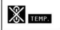
corner of the picture. If the temperature continues to rise, the lamp will turn off, the temperature warning indicator on the projector will blink, and after a 90-second cooling-off period the projector will enter the standby mode. Refer to "Maintenance Indicators" on page 83 for details.

Info
- The cooling fan regulates the internal temperature, and its performance is automatically controlled. The sound of the fan may change during projector operation due to changes in the fan speed. This does not indicate malfunction.
- Do not unplug the power cord during projection or cooling fan operation. This can create damage due to the rise in internal temperature, as the cooling fan also stops.
How to Access the PDF Operation Manuals (Windows, Macintosh)
PDF operation manuals in several languages are included in the CD-ROM, so that you can work with the projector, even if you do not have this manual. To utilize these manuals, you need to install Adobe Acrobat Reader on your PC (Windows or Macintosh). If you have not installed Acrobat Reader yet, you can install it from the CD-ROM.
To install Acrobat Reader from the CD-ROM
For Windows:
①Insert the CD-ROM in the CD-ROM drive.
② Double click the "My Computer" icon.
③ Double click the "CD-ROM" drive.
④ Double click the "ACROBAT" folder.
⑤Double click the language (name of the folder) that you want to view.
⑥Double click the installation program and follow the instructions on the screen.
For Macintosh:
①Insert the CD-ROM in the CD-ROM drive.
② Double click the "CD-ROM" icon.
③ Double click the "ACROBAT" folder.
④ Double click the language (name of the folder) that you want to view.
⑤Double click the installation program and follow the instructions on the screen.
For other operating systems:
Please download Acrobat Reader from the Internet (http://www.adobe.com).
For other languages:
If you prefer using Acrobat Reader for languages other than those included in the CD-ROM, please download the appropriate version from the Internet.
Accessing the PDF Manuals
For Windows:
①Insert the CD-ROM in the CD-ROM drive.
② Double click the "My Computer" icon.
③ Double click the "CD-ROM" drive.
④ Double click the "MANUALS" folder.
⑤Double click the language (name of the folder) that you want to view.
⑥ Double click the "C55X" pdf file to access the projector manuals.
For Macintosh:
①Insert the CD-ROM in the CD-ROM drive.
② Double click the "CD-ROM" icon.
③ Double click the "MANUALS" folder.
④ Double click the language (name of the folder) that you want to view.
⑤ Double click the "C55X" pdf file to access the projector manuals.

Note
- If the desired pdf file cannot be opened by double clicking the mouse, start Acrobat Reader first, then specify the desired file using the "File", "Open" menu.
- See the "readme.txt" file on the CD-ROM for important information not included in this operation manual.
Part Names
Numbers in refer to the main pages in this operation manual where the topic is explained.
Projector (Front and Top View)

In this operation manual, the illustration and the screen display are simplified for explanation, and may differ slightly from actual display.
Projector (Rear View)

Using the Kensington Lock
- This projector has a Kensington Security Standard connector for use with a Kensington MicroSaver Security System. Refer to the information that came with the system for instructions on how to use it to secure the projector.
Carrying the projector
Before carrying the projector, fully extend the carrying handle.

Remote Control (Front View)

Remote Control (Top View)
Using the Remote Control
Available Range of the Remote Control
■The remote control can be used to control the projector within the ranges shown in the illustration.

Note
- The signal from the remote control can be reflected off a screen for easy operation. However, the effective distance of the signal may differ due to the screen material.
When using the remote control:
- Be sure not to drop, expose to moisture or high temperature.
- The remote control may malfunction under a fluorescent lamp. Under that circumstance, move the projector away from the fluorescent lamp.

Inserting the Batteries
The batteries (two R-6 batteries ("AA" size, UM/SUM-3, HP-7 or similar)) are included in the package.
1 Pull down the tab on the cover and remove the cover towards the direction of the arrow.
2 Insert the included batteries.
- Insert the batteries making sure the polarities correctly match the ④ and - marks inside the battery compartment.
3 Insert the lower tab of the cover into the opening, and lower the cover until it clicks in place.


Incorrect use of the batteries may cause them to leak or explode. Please follow the precautions below.
Caution
- Insert the batteries making sure the polarities correctly match the ④ and marks inside the battery compartment.
- Batteries of different types have different properties, therefore do not mix batteries of different types.
- Do not mix new and old batteries.
This may shorten the life of new batteries or may cause old batteries to leak. -
Remove the batteries from the remote control once they have run out, as leaving them can cause them to leak. Battery fluid from leaked batteries is harmful to your skin, therefore be sure to first wipe them and then remove them using a cloth.
-
The batteries included with this projector may exhaust over a short period, depending on how they are kept. Be sure to replace them as soon as possible with new batteries.
- Remove the batteries from the remote control if you will not be using the remote control for a long time.
Supplied accessories

Remote control
RRMCGA176WJSA
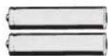
Two R-6 batteries
("AA" size, UM/SUM-3, HP-7 or similar)
Power cord
(1)

For U.S., Canada, etc.
(11'10" (3.6 m))
QACCDA010WJPZ
(2) (3)
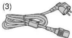
For Europe, except U.K.
(6' (1.8 m))
QACCVA011WJPZ

For U.K., Hong Kong and Singapore
(6' (1.8 m))
QACCBA012WJPZ
(4)

For Australia, New Zealand and Oceania (6' (1.8 m))
QACCLA014WJPZ

Note
- Use the power cord that corresponds to the wall outlet in your country.

RGB cable
(9'10" (3 m))
QCNWGA012WJPZ
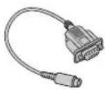
DIN-D-sub RS-232C adaptor (5 57/64" (15 cm)) QCNWGA015WJPZ

USB cable (3'3" (1 m))
QCNWG0007CEPZ
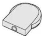
Remote receiver
RUNTKA061WJZZ
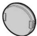
Lens cap (attached)
PCAPHA003WJSA

Extra air filter
PFILDA005WJZZ
Projector manual and technical reference
CD-ROM
UDSKAA035WJZZ
Sharp Advanced Presentation Software CD-ROM
UDSKAA036WJZZ
Sharp Advanced
Presentation Software
quick installation guide
TINS-A867WJZZ
Quick guide label
TLABZA364WJZZ
Operation manual (this manual)
Optional cables
■3 RCA to 15-pin D-sub cable (9'10" (3.0 m)) AN-C3CP
■ Computer RGB cable (32'10" (10.0 m)) AN-C10BM (15-pin mini D-sub male connector)
■5 BNC to 15-pin D-sub cable (9'10" (3.0 m)) AN-C3BN
■RS-232C serial control cable (32'10" (10.0 m)) AN-C10RS

Note
- Some of the cables may not be available depending on the region. Please check with your nearest Sharp Authorized Projector Dealer or Service Center.
Connections and Setup

Connecting the Projector to Other Devices
Before Connecting

Note
- Before connecting, be sure to unplug the power cord of the projector from the AC outlet and turn off the devices to be connected. After making all connections, turn on the projector and then the other devices. When connecting a computer, be sure that it is the last device to be turned on after all the connections are made.
- Be sure to read the operation manuals of the devices to be connected before making connections.
This projector can be connected to:
A computer using:
■An RGB cable and a computer audio cable (commercially available) (See page 17.)
■A DIN-D-sub RS-232C adaptor and an RS-232C serial control cable (AN-C10RS) (sold separately)
(See page 22.)

Component video or audio-visual equipment:
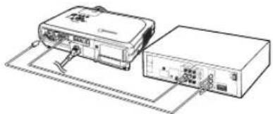
■A VCR, Laser disc player or other audio-visual equipment (See page 19.)
■ A DVD player or DTV* decoder (See page 20.)
*DTV is the umbrella term used to describe the new digital television system in the United States.

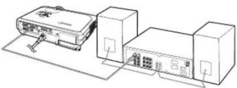
An amplifier or audio components using:
■ An audio cable (commercially available) (See page 21.)
A monitor using:
■An RGB cable (See page 23.)
■A computer RGB cable (AN-C10BM) (sold separately) (See page 23.)

Connecting the Power Cord
Plug in the supplied power cord into the AC socket on the rear of the projector.
Supplied accessory

Power code
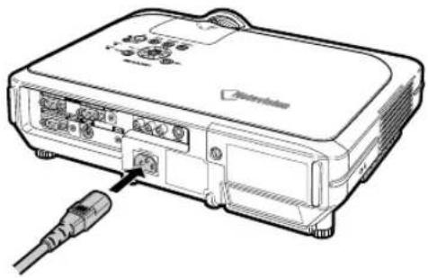
Connecting the Projector to a Computer
Connecting to a Computer Using the RGB Cable
1 Connect the projector to the computer using the supplied RGB cable.
- Secure the connectors by tightening the thumbscrews.
2 To input audio signal, connect the projector to the computer using the computer audio cable (commercially available or available as Sharp service part QCNWGA013WJPZ).

Note
• See page 93 "Computer Compatibility Chart" for a list of computer signals compatible with the projector. Use with computer signals other than those listed may cause some of the functions not to work.
- When connecting the projector to a computer in this way, select "RGB" for "Signal Type" in the "Picture" menu. See page 46.
- A Macintosh adaptor may be required for use with some Macintosh computers. Contact your nearest Sharp Authorized Projector Dealer or Service Center.
- Depending on the computer you are using, an image may not be projected unless the signal output setting of the computer is switched to the external output. Refer to the computer operation manual for switching the computer signal output settings.
Supplied accessory

RGB cable
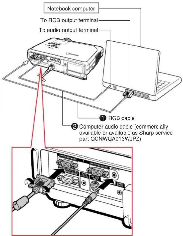
Connecting the thumbscrew cables
■Connect the thumbscrew cable making sure that it fits correctly into the terminal. Then, firmly secure the connectors by tightening the screws on both sides of the plug.
■Do not remove the ferrite core attached to the RGB cable.

"Plug and Play" function (when connecting to a 15-pin terminal)
This projector is compatible with VESA-standard DDC 1/DDC 2B. The projector and a VESA DDC compatible computer will communicate their setting requirements, allowing for quick and easy setup.
Before using the "Plug and Play" function, be sure to turn on the projector first and the connected computer last.

Note
- The DDC "Plug and Play" function of this projector operates only when used in conjunction with a VESA DDC compatible computer.
Connecting to Video Equipment
Connecting to Video Equipment Using an S-video, a Composite Video or an Audio Cable
Using an S-video, video, or audio cable, a VCR, laser disc player or other audio-visual equipment can be connected to INPUT 3, INPUT 4 and AUDIO (L/R) input terminals.
1 Connect the projector to the video equipment using an S-video cable or a composite video cable (both commercially available).
2 Connect the projector to the video equipment using an audio cable (commercially available).

Note
- The INPUT 4 (S-VIDEO) terminal uses a video signal system in which the picture is separated into color and luminance signals to realize a higher-quality image. To view a higher-quality image, use a commercially available S-video cable to connect the INPUT 4 terminal on the projector and the S-video output terminal on the video equipment.

Connecting to Component Video Equipment
Use a 3 RCA to 15-pin D-sub cable when connecting to the INPUT 1 or 2 terminal, component video equipment such as DVD players and DTV* decoders.
*DTV is the umbrella term used to describe the new digital television system in the United States.
1 Connect the projector to the video equipment using the 3 RCA to 15-pin D-sub cable.
2 Connect the projector to the video equipment using a φ 3.5 mm stereo minijack to RCA audio cable (commercially available).

Note
- When connecting the projector to the video equipment in this way, select "Component" for "Signal Type" in the "Picture" menu. See page 46.
- A 3.5 mm stereo minijack to RCA audio cable (commercially available) is required for audio input.
Optional cable
3RCA to 15-pin D-sub cable AN-C3CP (9'10" (3.0 m))

Connecting to an Amplifier
Connecting to an Amplifier or Other Audio Components
Using a φ 3.5 mm stereo minijack to RCA audio cable, an amplifier or other audio components can be connected to the AUDIO OUTPUT terminal.
Connect the projector to the amplifier using a 3.5 mm stereo minijack to RCA audio cable (commercially available).

Info
- By using external audio components, the volume can be amplified for better sound.
•The AUDIO OUTPUT terminal allows you to output audio to audio components from the selected AUDIO input terminal (for INPUT 1 and 2) or AUDIO (L/R) input terminals (for INPUT 3 and 4) connected to audiovisual equipment. - For details on Variable Audio Output (VAO) and Fixed Audio Output (FAO), see page 63.
- A 3.5 mm stereo minijack to RCA audio cable (commercially available) is required for audio input.

Controlling the Projector by a Computer
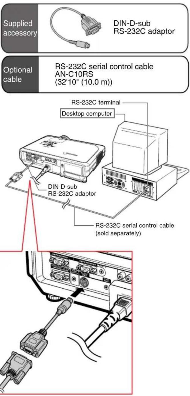
Connecting to a Computer Using a DIN-D-sub RS-232C Adaptor and an RS-232C Serial Control Cable
When the RS-232C terminal on the projector is connected to a computer with a DIN-D-sub RS-232C adaptor and an RS-232C serial control cable (cross type, sold separately), the computer can be used to control the projector and check the status of the projector. See page 89 for details.
1 Connect the supplied DIN-D-sub RS-232C adaptor to an RS-232C serial control cable (sold separately).
2 Use the above cables to connect the projector and the computer.

Note
- Do not connect or disconnect an RS-232C serial control cable to or from the computer while it is on. This may damage your computer.
- The RS-232C function may not operate if your computer terminal is not correctly set up. Refer to the operation manual of the computer for details.
• See page 88 for connection of an RS-232C serial control cable.
Connecting to a Monitor
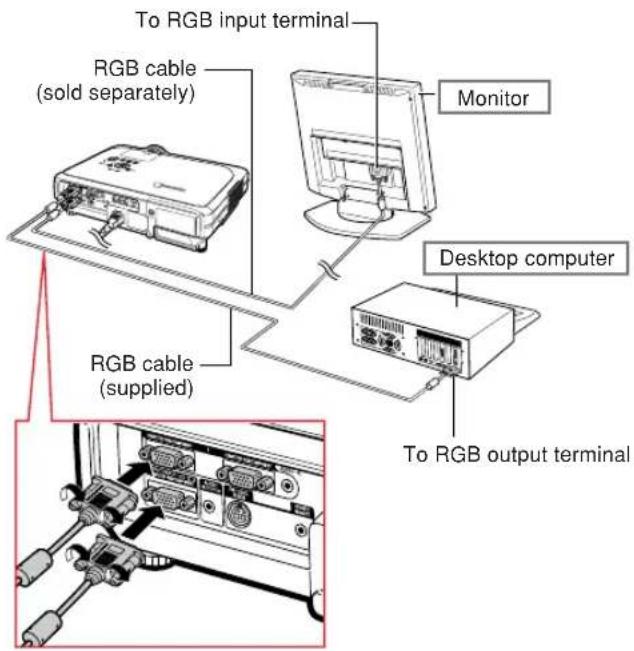
Watching Images on Both the Projector and a Monitor
You can display computer images on both the projector and a separate monitor using two sets of an RGB cable. An RGB cable is supplied with this projector. You need to buy another RGB cable for connecting the projector to a monitor.
1 Connect the projector to the computer and monitor using RGB cables (one is supplied, the other is sold separately).
2 In the “Options(1)” menu, select “Economy Mode”, “Mntr. out/RS232” and then “ON”. (see page 69.)

Note
- Analog RGB signals as well as Component signals can be output to the monitor.
Supplied accessory

RGB cable
Optional cable
Computer RGB cable AN-C10BM (32'10" (10.0 m))
Using as a Wired Remote Control
Connecting the Remote Control to the Projector
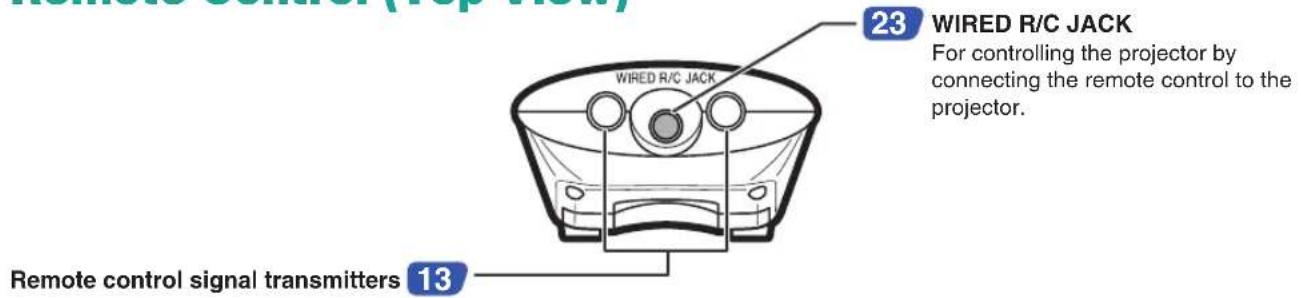
When the remote control cannot be used due to the range or positioning of the projector (rear projection, etc.), connect a 3.5 mm stereo or mono minijack cable (commercially available or available as Sharp service part QCNWGA013WJPZ) from the WIRED R/C JACK on the top of the remote control to the WIRED REMOTE control input terminal.

Note
• FORWARD/BACK presentation control cannot be used when the remote control is wired to the projector. To utilize this feature, disconnect the cable from the remote control.
WIRED REMOTE control input terminal

Using the Wireless Presentation Function of the Remote Control
By connecting the remote receiver to a computer, wireless presentation control is possible. BACK and FORWARD buttons on the remote control will emulate the [Page Up] and [Page Down] keys on your computer keyboard. This will allow you to remotely navigate applicable presentation programs such as Microsoft PowerPoint®.
Using the Wireless Presentation Function
1 Connect the remote receiver to the computer using the supplied USB cable.

Note
•This function only works with the Microsoft Windows OS and Mac OS. However, this function does not work with the following operation systems that do not support USB.
- Versions earlier than Windows 95.
- Versions earlier than Windows NT4.0.
- Versions earlier than Mac OS 8.5.
2 Press BACK or FORWARD while using presentation software on your computer.
- Press 📄 to move the page up.
- Press 📋 to move the page down.


Setup
Using the Adjustment Feet
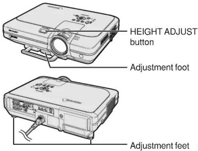
The height of the projector can be adjusted using the adjustment feet at the front and back of the projector when the surface the projector is placed on is uneven or when the screen is slanted.
The projection of the image can be made higher by adjusting the projector when it is in a location lower than the screen.
1 Press HEIGHT ADJUST.
2 Lift the projector to adjust its height and remove your finger from HEIGHT ADJUST.
3 Rotate the adjustment feet at the back of the projector for fine adjustment.

Note
- When returning the projector to its original position, hold the projector firmly, press HEIGHT ADJUST and then gently lower it.
- The projector is adjustable up to approximately 12 degrees on the front and 3 degrees on the back from the standard position.

Info
- Do not press HEIGHT ADJUST when the adjustment foot is extended without firmly holding the projector.
- Do not hold the lens when lifting or lowering the projector.
- When lowering the projector, be careful not to get your finger caught in the area between the adjustment foot and the projector.


Adjusting the Lens
The image is focused and adjusted to the desired size using the focus ring or zoom knob on the projector.
1 The focus is adjusted by rotating the focus ring.
2 Zooming is adjusted by moving the zoom knob.

Setting up the Screen
Position the projector perpendicular to the screen with all feet flat and level to achieve an optimal image.

Note
- The projector lens should be centered in the middle of the screen. If the horizontal line passing through the lens center is not perpendicular to the screen, the image will be distorted, making viewing difficult.
- For optimal image, position the screen so that it is not in direct sunlight or room light. Light falling directly on the screen washes out the colors, making viewing difficult. Close the curtains and dim the lights when setting up the screen in a sunny or bright room.
•A polarizing screen cannot be used with this projector.
Three optional lenses from Sharp are also available for specialized application. Contact your local Sharp Authorized Projector Dealer for details on the lens. (Refer to the lens installation manual when attaching a lens.)
Throw Distance
■The graph below is for 100 inches (254 cm) screen with 4:3 normal mode.
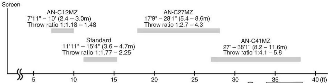
Standard Setup (Front Projection)
■Place the projector at the required distance from the screen according to the desired picture size. (See page 28.)
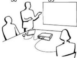
Example of Standard Setup
Side View
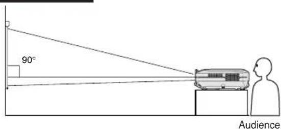
•The distance from the screen to the projector may vary depending on the size of the screen.
P.28
- The default setting can be used, when placing the projector in front of the screen. If the projected image is reversed or inverted, readjust the setting to "Front" in "PRJ Mode". P.71
Top View

- Place the projector so that an imaginary horizontal line that passes through the center of the lens is perpendicular to the screen.
Screen Size and Projection Distance

Standard Lens
Throw ratio
1:1.77 to 2.25
NORMAL Mode (4:3)
| Picture (Screen) size | Projection distance [L] | Distance from the lens center to the bottom of the image [H] | |||
| Diag. [x] | Width | Height | Maximum [L1] | Minimum [L2] | |
| 300" (762 cm) | 240" (610 cm) | 180"(457 cm) | 46' 4" (14.1 m) | 36' (11.0 m) | 17 11/16" (45.0 cm) |
| 250" (635 cm) | 200" (508 cm) | 50" (381 cm) | 38' 7" (11.8 m) | 30' (9.1 m) | 14 3/4" (37.5 cm) |
| 200" (508 cm) | 160" (406 cm) | 120" (305 cm) | 30'10" (9.4 m) | 24' (7.3 m) | 11 13/16" (30.0 cm) |
| 150" (381 cm) | 120" (305 cm) | 90" (229 cm) | 23' 1" (7.0 m) | 17'11" (5.5 m) | 8 7/8" (22.5 cm) |
| 100" (254 cm) | 80" (203 cm) | 60" (152 cm) | 15' 4" (4.7 m) | 11'11" (3.6 m) | 5 7/8" (15.0 cm) |
| 84" (213 cm) | 67" (170 cm) | 50" (127 cm) | 12'11" (3.9 m) | 10' (3.0 m) | 4 15/16" (12.6 cm) |
| 72" (183 cm) | 58" (147 cm) | 43" (109 cm) | 11' (3.4 m) | 8' 6" (2.6 m) | 4 1/4" (10.8 cm) |
| 60" (152 cm) | 48" (122 cm) | 36" (91 cm) | 9' 2" (2.8 m) | 7' 1" (2.2 m) | 3 9/16" (9.0 cm) |
| 40" (102 cm) | 32" (81 cm) | 24" (61 cm) | 6' 1" (1.8 m) | 4' 8" (1.4 m) | 2 3/8" (6.0 cm) |
The formula for picture size and projection distance
X: Picture size (diag.) (in)
[Feet, inches]
L1 (ft) = (0.0472x - 0.0517) / 0.3048
L2 (ft) = (0.0367x - 0.0529) / 0.3048
H (in) = (0.1499X - 0.0064) / 2.54
[m, cm]
L1 (m) = 0.0472x - 0.0517
L2 (m) = 0.0367× - 0.0529
H (cm) = 0.1499x - 0.0064
STRETCH Mode (16:9)
| Picture (Screen) size Projection distance [L] | Distance from the lens center to the bottom of the image [H] | |||||
| Diag. [x] | Width Height | Maximum [L1] | Minimum [L2] | |||
| 300" (762 cm) | 261" (663 cm) | 147" (373 cm) | 50' 6" (15.4 m) | 39' 3" (12.0 m) | -4 15 / 16"(-12.6 cm) | |
| 250" (635 cm) | 218" (554 cm) | 123" (312 cm) | 42' (12.8 m) | 32' 8" (10.0 m) | -4 1 / 8"(-10.5 cm) | |
| 225" (572 cm) | 196" (498 cm) | 110" (279 cm) | 37'10" (11.5 m) | 29' 5" (9.0 m) | -3 3 / 4" (-9.5 cm) | |
| 200" (508 cm) | 174" (442 cm) | 98" (249 cm) | 33' 7" (10.2 m) | 26' 1" (8.0 m) | -3 5 / 16"(-8.4 cm) | |
| 150" (381 cm) | 131" (333 cm) | 74" (188 cm) | 25' 2" (7.7 m) | 19' 7" (6.0 m) | -2 1 / 2" (-6.3 cm) | |
| 133" (338 cm) | 116" (295 cm) | 65" (165 cm) | 22' 3" (6.8 m) | 17' 4" (5.3 m) | -2 3 / 16"(-5.6 cm) | |
| 106" (269 cm) | 92" (234 cm) | 52" (132 cm) | 17' 9" (5.4 m) | 13' 9" (4.2 m) | -1 3 / 4" (-4.5 cm) | |
| 100" (254 cm) | 87" (221 cm) | 49" (124 cm) | 16' 9" (5.1 m) | 13' (4.0 m) | -1 5 / 8" (-4.2 cm) | |
| 92" (234 cm) | 80" (203 cm) | 45" (114 cm) | 15' 5" (4.7 m) | 11' 11" (3.6 m) | -1 9 / 16"(-3.9 cm) | |
| 84" (213 cm) | 73" (185 cm) | 41" (104 cm) | 14' (4.3 m) | 10' 11" (3.3 m) | -1 3 / 8" (-3.5 cm) | |
| 72" (183 cm) | 63" (160 cm) | 35" (89 cm) | 12' (3.7 m) | 9' 4" (2.8 m) | -1 3 / 16"(-3.0 cm) | |
| 60" (152 cm) | 52" (132 cm) | 29" (74 cm) | 10' (3.0 m) | 7' 9" (2.4 m) | -31 / 32"(-2.5 cm) | |
| 40" (102 cm) | 35" (89 cm) | 20" (51 cm) | 6' 7" (2.0 m) | 5' 2" (1.6 m) | -11 / 16"(-1.7 cm) | |
The formula for picture size and projection distance
X: Picture size (diag.) (in)
[Feet, inches]
L1 (ft) = (0.0514X - 0.0516) / 0.3048
L2 (ft) = (0.04X - 0.0523) / 0.3048
H (in) = (-0.0422X + 0.0018) / 2.54
[m, cm]
L1 (m) = 0.0514X - 0.0516
L2 (m) = 0.04x - 0.0523
H (cm) = -0.0422x + 0.0018
![SHARP XG-C55X - [m, cm] - 1](/content/2026/08/1623398/images/24208de95a6aa5bf144c389cbc139681155e8980487a0e4e5593fb3702c634a1.jpg)
Note
• There is an error of ± 3% in the formula above.
- Values with a minus (−) sign indicate the distance of the lens center below the bottom of the image.
AN-C41MZ (Optional accessory)
Throw ratio
1:4.1 to 5.8
NORMAL Mode (4:3)
| Picture (Screen) size | Projection distance [L] | Distance from the lens center to the bottom of the image [H] | |||
| Diag. [ ] | Width | Height | Maximum [L1] | Minimum [L2] | |
| 300" (762 cm) | 240" (610 cm) | 180" (457 cm) | 114' 6" (34.9 m) | 81' (24.7 m) | 17 7/8" (45.4 cm) |
| 250" (635 cm) | 200" (508 cm) | 150" (381 cm) | 94' 10" (28.9 m) | 67' 2" (20.5 m) | 14 7/8" (37.8 cm) |
| 200" (508 cm) | 160" (406 cm) | 120" (305 cm) | 75' 11" (23.1 m) | 53' 9" (16.4 m) | 11 59/64" (30.3 cm) |
| 150" (381 cm) | 120" (305 cm) | 90" (229 cm) | 57" (17.4 m) | 40' 5" (12.3 m) | 8 15/16" (22.7 cm) |
| 100" (254 cm) | 80" (203 cm) | 60" (152 cm) | 38' 1" (11.6 m) | 27' (8.2 m) | 5 15/16" (15.1 cm) |
| 84" (213 cm) | 67" (170 cm) | 50" (127 cm) | 32' 1" (9.8 m) | 22' 9" (6.9 m) | 5" (12.7 cm) |
| 72" (183 cm) | 58" (147 cm) | 43" (109 cm) | 27' 6" (8.4 m) | 19' 7" (6.0 m) | 4 19/64" (10.9 cm) |
| 60" (152 cm) | 48" (122 cm) | 36" (91 cm) | 23' (7.0 m) | 16' 4" (5.0 m) | 3 37/64" (9.1 cm) |
| 40" (102 cm) | 32" (81 cm) | 24" (61 cm) | 15' 5" (4.7 m) | 11' (3.4 m) | 2 23/64" (6.0 cm) |
The formula for picture size and projection distance
χ: Picture size (diag.) (in)
[Feet, inches]
L1 (ft) = (0.1158x + 0.0403) / 0.3048
L2 (ft) = (0.0818x + 0.0606) / 0.3048
H (in) = (0.1514X - 0.0071) / 2.54
[m, cm]
L1 (m) = 0.1158x + 0.0403
L2 (m) = 0.0818x + 0.0606
H (cm) =0.1514X - 0.0071
STRETCH Mode (16:9)
| Picture (Screen) size Projection distance [L] | Distance from the lens center to the bottom of the image [H] | |||||
| Diag. [X] | Width Height | Maximum [L1] Minimum [L2] | ||||
| 300" (762 cm) | 251"(663 cm) | 147" (373 cm) | 123' 10" (37.8 m) | 87' 9" (26.8 m) | -5 3/64"(-12.8 cm) | |
| 250" (635 cm) | 218"(554 cm) | 123" (312 cm) | 103' 3" (31.5 m) | 73' 2" (22.3 m) | -4 11/64"(-10.6 cm) | |
| 225" (572 cm) | 196"(498 cm) | 110" (279 cm) | 93' (28.3 m) | 65' 11" (20.1 m) | -3 25/32" (-9.6 cm) | |
| 200" (508 cm) | 174"(442 cm) | 98" (249 cm) | 82' 8" (25.2 m) | 58' 8" (17.9 m) | -3 11/32" (-8.5 cm) | |
| 150" (381 cm) | 131"(333 cm) | 74" (188 cm) | 62' 1" (18.9 m) | 44' (13.4 m) | -2 33/64" (-6.4 cm) | |
| 133" (338 cm) | 116"(295 cm) | 65" (165 cm) | 55' 1" (16.8 m) | 39' 1" (11.9 m) | -2 1/4" (-5.7 cm) | |
| 106" (269 cm) | 92' 523(432cm) | 44' (13.4 m) | 31' 2" (9.5 m) | -1 49/64" (-4.5 cm) | ||
| 100" (254 cm) | 87" (221 cm) | 49" (124 cm) | 41' 6" (12.7 m) | 29' 6" (9.0 m) | -1 11/16" (-4.3 cm) | |
| 92" (234 cm) | 80" (203 cm) | 45" (114 cm) | 38' 2" (11.6 m) | 27' 2" (8.3 m) | -1 17/32" (-3.9 cm) | |
| 84" (213 cm) | 78" (185 cm) | 41" (104 cm) | 34' 11" (10.6 m) | 24' 10" (7.6 m) | -1 27/64" (-3.6 cm) | |
| 72" (183 cm) | 68" 35"(189 cm) | 29' 11" (9.1 m) | 21' 4" (6.5 m) | -1 7/32" (-3.1 cm) | ||
| 60" (152 cm) | 52" 29"(179 cm) | 25' (7.6 m) | 17' 10" (5.4 m) | -1 1/32" (-2.6 cm) | ||
| 40" (102 cm) | 35"(89 cm) | 20" (51 cm) | 16' 10" (5.1 m) | 12' (3.7 m) | -43/64" (-1.7 cm) | |
The formula for picture size and projection distance
χ: Picture size (diag.) (in)
[Feet, inches]
L1 (ft) = (0.1255x + 0.0951) / 0.3048
L2 (ft) = (0.0888x + 0.0975) / 0.3048
H (in) = (-0.0425x - 0.001) / 2.54
[m, cm]
L1 (m) = 0.1255x + 0.0951
L2 (m) = 0.0888x + 0.0975
H (cm) = -0.0425 x - 0.001
![SHARP XG-C55X - [m, cm] - 1](/content/2026/08/1623398/images/3f42d01df5f75b7cd469a0633a27db9b7fbe386d7f2b7a4f4094275b40dd0aa9.jpg)
Note
•There is an error of ± 3% in the formula above.
- Values with a minus (−) sign indicate the distance of the lens center below the bottom of the image.
AN-C27MZ (Optional accessory)
Throw ratio
1:2.7 to 4.3
NORMAL Mode (4:3)
| Picture (Screen) size | Projection distance [L] | Distance from the lens center to the bottom of the image [H] | ||||
| Diag. [ ] | Width | Height | Maximum [L1] | Minimum [L2] | ||
| 300" (762 cm) | 240" (610 cm) | 180" (457 cm) | 85' 2" (26.0 m) | 54' 2" (16.5 m) | 17 63 / 64" (45.7 cm) | |
| 250" (635 cm) | 200" (508 cm) | 50" (381 cm) | 70' 11" (21.6 m) | 45' 1" (13.7 m) | 14 61 / 64" (38.0 cm) | |
| 200" (508 cm) | 160" (406 cm) | 120" (305 cm) | 56' 8" (17.3 m) | 36' (11.0 m) | 11 31 / 32" (30.4 cm) | |
| 150" (381 cm) | 120" (305 cm) | 90" (229 cm) | 42' 4" (12.9 m) | 26' 10" (8.2 m) | 8 31 / 32" (22.8 cm) | |
| 100" (254 cm) | 80" (203 cm) | 60" (152 cm) | 28' 1" (8.6 m) | 17' 9" (5.4 m) | 5 63 / 64" (15.2 cm) | |
| 84" (213 cm) | 67" (170 cm) | 50" (127 cm) | 23' 6" (7.2 m) | 14' 10" (4.5 m) | 5 3 / 64" (12.8 cm) | |
| 72" (183 cm) | 58" (147 cm) | 43" (109 cm) | 20' 1" (6.1 m) | 12' 8" (3.9 m) | 4 21 / 64" (11.0 cm) | |
| 60" (152 cm) | 48" (122 cm) | 36" (91 cm) | 16' 8" (5.1 m) | 10' 6" (3.2 m) | 3 37 / 64" (9.1 cm) | |
| 40" (102 cm) | 32" (81 cm) | 24" (61 cm) | 11' (3.4 m) | 6' 10" (2.1 m) | 2 13 / 32" (6.1 cm) | |
The formula for picture size and projection distance
X: Picture size (diag.) (in)
[Feet, inches]
L1 (ft) = (0.087x - 0.1353) / 0.3048
L2 (ft) = (0.0555x - 0.1377) / 0.3048
H (in) = (0.1522x - 0.002) / 2.54
[m, cm]
L1 (m) = 0.087x -0.1353
L2 (m) = 0.0555x - 0.1377
H (cm) =0.1522x - 0.002
STRETCH Mode (16:9)
| Picture (Screen) size Projection distance [L] | Distance from the lens center to the bottom of the image [H] | |||||
| Diag. [X] | Width | Height | Maximum [L1] Minimum [L2] | |||
| 300" (762 cm) | 261 " (663 cm) | 147" (373 cm) | 92' 8" (28.3 m) | 59' 1" (18.0 m) | -5" (-12.7 cm) | |
| 250" (635 cm) | 218 " (554 cm) | 123" (312 cm) | 77' 2" (23.5 m) | 49' 2" (15.0 m) | -4 11 / 64" (-10.6 cm) | |
| 225' (572 cm) | 196" (498 cm) | 110" (279 cm) | 69' 5" (21.2 m) | 44' 3" (13.5 m) | -3 47 / 64" (-9.5 cm) | |
| 200" (508 cm) | 174 " (442 cm) 98 | "(249 cm) | 61' 8" (18.8 m) | 39' 3" (12.0 m) | -3 11 / 32" (-8.5 cm) | |
| 150" (381 cm) | 131 " (333 cm) 74 | "(188 cm) | 46' 2" (14.1 m) | 29' 4" (8.9 m) | -2 33 / 64" (-6.4 cm) | |
| 133' (338 cm) | 116" (295 cm) 65 | "(165 cm) | 40' 10" (12.5 m) | 25' 11" (7.9 m) | -2 13 / 64" (-5.6 cm) | |
| 106' (269 cm) | 92" (234 cm) 52 | (132 cm) | 32' 6" (9.9 m) | 20' 7" (6.3 m) | -1 49 / 64" (-4.5 cm) | |
| 100' (254 cm) | 87" (221 cm) | 49" (124 cm) | 30' 7" (9.3 m) | 19' 5" (5.9 m) | -1 21 / 32" (-4.2 cm) | |
| 92" (234 cm) | 80" (203 cm) | 45" (114 cm) | 28' 1" (8.6 m) | 17' 10" (5.4 m) | -1 17 / 32" (-3.9 cm) | |
| 84" (213 cm) | 73" (185 cm) | 41" (104 cm) | 25' 7" (7.8 m) | 16' 2" (4.9 m) | -1 27 / 64" (-3.6 cm) | |
| 72" (183 cm) | 63" (160 cm) 35" (89 cm) | 21' 11" (6.7 m) | 13' 10" (4.2 m) | -1 7 / 32" (-3.1 cm) | ||
| 60" (152 cm) | 52" (132 cm) 29" (74 cm) | 18' 2" (5.5 m) | 11' 5" (3.5 m) | -63 / 64" (-2.5 cm) | ||
| 40" (102 cm) | 35" (89 cm) 20" (51 cm) | 12' (3.7 m) | 7' 6" (2.3 m) | -43 / 64" (-1.7 cm) | ||
The formula for picture size and projection distance
χ: Picture size (diag.) (in)
[Feet, inches]
L1 (ft) = (0.0946x - 0.1356) / 0.3048
L2 (ft) = (0.0605x - 0.1377) / 0.3048
H (in) = (-0.0424x + 0.0013) / 2.54
[m, cm]
L1 (m) = 0.0946x - 0.1356
L2 (m) = 0.0605x - 0.1377
H (cm)=-0.0424x+0.0013
![SHARP XG-C55X - [m, cm] - 1](/content/2026/08/1623398/images/29297c07324238071bf9e3e40db6d6788333cfd522506883f66666e0b3b87f8f.jpg)
Note
•There is an error of ± 3% in the formula above.
- Values with a minus (−) sign indicate the distance of the lens center below the bottom of the image.
AN-C12MZ (Optional accessory)
Throw ratio
1:1.18 to 1.48
NORMAL Mode (4:3)
| Picture (Screen) size | Projection distance [L] | Distance from the lens center to the bottom of the image [H] | |||
| Diag. [ ] | Width | Height | Maximum [L1] | Minimum [L2] | |
| 300" (762 cm) | 240" (610 cm) | 180" (457 cm) | 30' 5" (9.3 m) | 24' 3" (7.4 m) | 17 3/4" (45.1 cm) |
| 250" (635 cm) | 200" (508 cm) | 150" (381 cm) | 25' 4" (7.7 m) | 20' 2" (6.1 m) | 14 13/16" (37.6 cm) |
| 200" (508 cm) | 160" (406 cm) | 120" (305 cm) | 20' 3" (6.2 m) | 16' 1" (4.9 m) | 11 13/16" (30.0 cm) |
| 150" (381 cm) | 120" (305 cm) | 90" (229 cm) | 15' 2" (4.6 m) | 12' (3.7 m) | 8 7/8" (22.5 cm) |
| 100" (254 cm) | 80" (203 cm) | 60" (152 cm) | 10' (3.0 m) | 7' 11" (2.4 m) | 5 7/8" (15.0 cm) |
| 84" (213 cm) | 67" (170 cm) | 50" (127 cm) | 8' 4" (2.5 m) | 6' 8" (2.0 m) | 4 15/16" (12.6 cm) |
| 72" (183 cm) | 58" (147 cm) | 43" (109 cm) | 7' 2" (2.2 m) | 5' 8" (1.7 m) | 4 1/4" (10.8 cm) |
| 60" (152 cm) | 48" (122 cm) | 36" (91 cm) | 5'11" (1.8 m) | 4' 8" (1.4 m) | 3 9/16" (9.0 cm) |
| 40" (102 cm) | 32" (81 cm) | 24" (61 cm) | 3'11" (1.2 m) | 3' 1" (0.9 m) | 2 3/8" (6.0 cm) |
The formula for picture size and projection distance
X: Picture size (diag.) (in)
[Feet, inches]
L1 (ft) = (0.0311X - 0.0676) / 0.3048
L2 (ft) = (0.0248x - 0.0693) / 0.3048
H (in) = (0.1504X - 0.0328) / 2.54
[m, cm]
L1 (m) = 0.0311x - 0.0676
L2 (m) = 0.0248X - 0.0693
H (cm) = 0.1504X - 0.0328
STRETCH Mode (16:9)
| Picture (Screen) size Projection distance [L] | Distance from the lens center to the bottom of the image [H] | ||||||
| Diag. [x] | Width Height | Maximum [L1] Minimum [L2] | |||||
| 300" (762 cm) | 261 " (663 cm) | 147" (373 cm) | 33' 2" (10.1 m) 26' | 5" (8.0 m) -5" | (-12.7 cm) | ||
| 250" (635 cm) | 218 " (554 cm) | 123" (312 cm) | 27' 7" (8.4 m) | 22' (6.7 m) | -4 | 3 / 16"(-10.6 cm) | |
| 225" (572 cm) | 196" (498 cm) | 110" (279 cm) | 24'10" (7.6 m) | 19' 9" (6.0 m) | -3 | 3 / 4" (-9.5 cm) | |
| 200" (508 cm) | 174 " (442 cm) 98 | "(249 cm) | 22' 1" (6.7 m) | 17' 7" (5.3 m) | -3 | 3 / 8" (-8.5 cm) | |
| 150" (381 cm) | 31 " (333 cm) 74 | "(188 cm) | 16' 6" (5.0 m) | 13' 2" (4.0 m) | -2 | 1 / 2" (-6.4 cm) | |
| 133" (338 cm) | 116" (295 cm) 65 | "(165 cm) | 14' 7" (4.4 m) | 11' 7" (3.5 m) | -2 | 3 / 16"(-5.6 cm) | |
| 106" (269 cm) | 92" (234 cm) 52' | (132 cm) | 11' 7" (3.5 m) | 9' 3" (2.8 m) | -1 | 3 / 4" (-4.5 cm) | |
| 100" (254 cm) | 87" (221 cm) | 49" (124 cm) | 10'11" (3.3 m) | 8' 8" (2.6 m) | -1 | 5 / 8" (-4.2 cm) | |
| 92" (234 cm) | 80" (203 cm) | 45" (114 cm) | 10' 1" (3.1 m) | 8' (2.4 m) | -1 | 9 / 16"(-3.9 cm) | |
| 84" (213 cm) | 73" (185 cm) | 41" (104 cm) | 9' 2" (2.8 m) | 7' 3" (2.2 m) | -1 | 7 / 16"(-3.6 cm) | |
| 72" (183 cm) | 63" (160 cm) 35" (89 cm) | 7'10" (2.4 m) | 6' 3" (1.9 m) | -1 | 3 / 16"(-3.0 cm) | ||
| 60" (152 cm) | 52" (132 cm) 29" (74 cm) | 6' 6" (2.0 m) | 5' 2" (1.6 m) | -31 / 32"(-2.5 cm) | |||
| 40" (102 cm) | 35" (89 cm) 20' (51 cm) | 4' 3" (1.3 m) | 3' 4" (1.0 m) | -11 / 16"(-1.7 cm) | |||
The formula for picture size and projection distance
X: Picture size (diag.) (in)
[Feet, inches]
L1 (ft) = (0.0339x - 0.0669) / 0.3048
L2 (ft) = (0.027x - 0.0683) / 0.3048
H (in) = (-0.0424X + 0.0079) / 2.54
[m, cm]
L1 (m) = 0.0339x - 0.0669
L2 (m) = 0.027x - 0.0683
H (cm) = -0.0424X + 0.0079
![SHARP XG-C55X - [m, cm] - 1](/content/2026/08/1623398/images/f3c84958d87832e155363a34753030c692521062e904706c5fa91d33bfe7a5c2.jpg)
Note
- There is an error of ± 3% in the formula above.
- Values with a minus (−) sign indicate the distance of the lens center below the bottom of the image.
Projecting a Reversed/Inverted Image
Projection from behind the screen
■Place a translucent screen between the projector and the audience.
■ Reverse the image by setting "Rear" in "PRJ Mode". See page 71 for use of this function.

Projection using a mirror
■Place a mirror (normal flat type) in front of the lens.


Info
- When using a mirror, be sure to carefully position both the projector and the mirror so the light does not shine into the eyes of the audience.
Ceiling-mount setup
■It is recommended that you use the optional Sharp ceiling-mount bracket for this installation.
Before mounting the projector, contact your nearest Sharp Authorized Projector Dealer or Service Center to obtain the recommended ceiling-mount bracket (sold separately).
- AN-XGCM55 ceiling-mount bracket, its AN-EP101B extension tube and AN-JT200 universal bracket, adaptor for non-level ceiling installation (for U.S.A.).
- BB-M20T ceiling adaptor, its BB-NVHOLDER280, BB-NVHOLDER550, BB-NVHOLDER900 ceiling mount systems (for GERMANY).
• AN-60KT ceiling-mount bracket, its AN-TK201 and AN-TK202 extension tubes (for countries other than the U.S.A. and GERMANY).
■Be sure to adjust the position of the projector to match the distance (H) from the lens center position (see page 28) to the lower edge of the image, when mounting the projector on the ceiling.
■Invert the image by setting "Ceiling + Front" in "PRJ Mode". See page 71 for use of this function.

When using the default setting.
▼On-screen Display
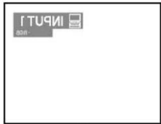

The image is reversed.
When using the default setting.
▼On-screen Display


The image is inverted.
Basic Operation
Basic Procedure
Connect the required external equipment to the projector before operating the following procedures.

Info
- The language preset at the factory is English. If you want to change the on-screen display to another language, reset the language according to the procedure on page 36.
1 Plug the power cord into the wall outlet.
- The power indicator illuminates red, and the projector enters the standby mode.
2 Press ON on the projector or on the remote control.
- The power indicator illuminates green. After the lamp indicator illuminates, the projector is ready to start operation.

Note
- The lamp indicator illuminates, indicating the status of the lamp. Green: The lamp is ready. Green blinking: The lamp is
Green blinking: The lamp is warming up or shutting down.
Red: The lamp should be replaced.
- If the projector is put into the standby mode and immediately turned on again, the lamp indicator may take time to illuminate.
- When controlling the projector using RS-232C commands from a computer, wait for at least 40 seconds after the power has been turned on, and then transmit the commands.
When "Anti-Theft" (see page 75) is set, the keycode input box will appear.
- Enter the keycode.

Note
- When entering the keycode, press the buttons previously set on the projector or the remote control.

Info
- When "Anti-Theft" is set, enter the keycode or the input display will not appear. Even when the signal is input, the display will not appear. (see page 75.)


▼Keycode input box

3
INPUT 1
INPUT 2
INPUT3
INPUT 4


the remote control to select the INPUT mode.
• After pressing 📋 once on the projector, use ⏻ select the desired input mode.

Note
- When no signal is received, "NO SIGNAL." will be displayed. When a signal that the projector is not pre-set to receive is received, "NOT REG." will be displayed.
- When "Auto Search" is "ON", the INPUT modes with signals can be selected. (see page 64.)
- The INPUT mode is not displayed when "OSD display" is set to "Level A" or "Level B". (see page 65.)
About the INPUT modes
| INPUT 1INPUT 2(RGB/Component) | Used for projecting images from equipment that sends RGB signals or component signals connected to the RGB input terminal. |
| INPUT 3(Video) | Used for projecting images from equipment connected to the VIDEO input terminal. |
| INPUT 4(S-Video) | Used for projecting images from equipment connected to the S-VIDEO input terminal. |
4


on the remote
control to adjust the volume.

Note
- Pressing ⏻ will lower the volume.
Pressing + will raise the volume. - On the projector, the volume can be
adjusted by pressing
on the projector operate buttons (\, |) when the en is active.


"On-screen Display (Example)"
![graph TD A["INPUT 1 mode"] --> B["Using RGB"] B --> C["INPUT 1 -RGB"] D["Using Component"] --> E["INPUT 1 -Component"] F["INPUT 2 mode"] --> G["Using RGB"] G --> H["INPUT 2 -RGB"] I["Using Component"] --> J["INPUT 2 -Component"] K["INPUT 3 mode"] --> L["Using Video"] M["INPUT 4 mode"] --> N["Using S…](/content/2026/08/1623398/images/b8f4908d8505446990db3a1f8646f8b32fb68fb5532ac5ac0d47130856c16454.jpg)

VOLUME
25


5
MUTE
Press to temporarily turn off the sound.

Note
- Pressing 📂 again will turn the sound back on.
Selecting the On-screen Display Language
The on-screen display language of the projector can be set to English, German, Spanish, Dutch, French, Italian, Swedish, Portuguese, Chinese, Korean or Japanese.
1
Press

•The menu will be displayed.
2
Press ◀ or ▶ to select “Language”.
3
Press ▲ or ▼ to select the desired language, and then press

4
Press
- The desired language will be set as the on-screen display.

MUTE

Turning the Power off
1
Press STANDBY on the projector or ON the remote control, then press that button again while the confirmation message is displayed, to put the projector into the standby mode.

Note
- If you accidentally pressed STANDBY or and do not want to put the projector into the standby mode, wait until the confirmation message disappears.
- The projector cannot be operated while a message "Shutting Down. Please Wait." is displayed.
2
Unplug the power cord from the AC outlet after the cooling fan stops.

Info
- Do not unplug the power cord during projection or cooling fan operation. This can cause damage due to the rise in internal temperature, as the cooling fan also stops.


Enter STANDBY mode?
Yes: Press Again No: Please Wait
Shutting Down. Please Wait.
Correcting Trapezoidal Distortion (Keystone Correction)
Correcting Trapezoidal Distortion
This function allows for Keystone (On-screen Trapezoidal Distortion) Correction.

Note
- When the image is projected either from top or from bottom towards the screen at an angle, the image becomes distorted trapezoidally.
The function for correcting trapezoidal distortion is called Keystone Correction.
• The Keystone Correction can be adjusted up to angle of approximately ±35 degrees.
1
Press

- Pressing 📋 again while the BORDER, STRETCH or SMART STRETCH screen is displayed will start the Digital Shift function. See page 39.
2
Press ▲, ▼, ◀ and ▶ to adjust the Keystone correction.
- If you want to make more detailed corrections, press ⚙️ to display the test pattern, and then press ▲, ▼, ◀ and ▶ to make the adjustments.

Note
- Since the trapezoidal distortion of the image can be corrected up to an angle of approximately ±35 degrees, the actual screen can be diagonally set up to that angle as well.
- Press UNDO to cancel Keystone Correction.
- When no signal is detected, the test pattern will be displayed without pressing
3
Press


Note
- You can use the same settings used in NORMAL mode 4:3 for 16:9.
- Straight lines or the edges of images may appear jagged while adjusting the image.

Test pattern

Digital Shift Setting
For easier viewing, this function shifts the entire image projected on the screen up or down when projecting 16:9 images from DVD players and DTV* decoders.
* DTV is the umbrella term used to describe the new digital television system in the United States.
![graph TD A["UNDO button"] --> B["Digital Shift"] A --> C["Control buttons"] B --> D["User Interface"] C --> E["User Interface"] D --> F["User Interface"] E --> G["User Interface"] F --> H["User Interface"] G --> I["User Interface"] H --> J["User Interface"] I --> K["User Interface"] J --> L["User In…](/content/2026/08/1623398/images/f0fc118d4a2203878f1d69f48087c2e2ccb2da2fb04144925ef9df2b0b4cdd7a.jpg)
Press ▲ to move the projected image upwards. Press UNDO to reset the image.
Press ▼ to move the projected image downwards. Press UNDO to reset the image.

Note
- The Digital Shift function works with BORDER, STRETCH or SMART STRETCH screen. For details, see page 53.
•To access Digital Shift function, press ☑ twice.
The Digital Shift menu will appear when a compatible 16:9 signal is displayed.
This list shows the items that can be set in the projector.
■ INPUT 1 / 2 Mode
![graph TD A["Main menu Sub menu"] --> B["Picture"] A --> C["C.M.S."] A --> D["Fine Sync"] B --> E["Contrast ←+30-30"] B --> F["Bright ←+30-30"] B --> G["Color ←+30-30"] B --> H["Tint ←+30-30"] B --> I["Sharp ←+30-30"] B --> J["Red ←+30-30"] B --> K["Blue ←+30-30"] B --> L["CLR Temp -3 ←+3"] B --> M["…](/content/2026/08/1623398/images/1eefc87e666266afeeb5d1c59b5a1997227c8ff7c6fdf6be589c5432a0e2f4db.jpg)

Note
- The resolution, vertical frequency and horizontal frequency figures displayed above are for example purposes only.
- Only when the signal type is set as "Component", in the "Picture" menu of INPUT 1 or 2 "Color", "Tint" and "Sharp" are displayed.
- Some items cannot be reset, even when "All Reset" in Options (2) has been selected. For details see page 77.
■ INPUT 3 / 4 Mode
![graph TD A["Main menu Sub menu Main menu Sub menu"] --> B["Picture"] B --> C1["Contrast ←+30-30"] B --> C2["Bright ←+30-30"] B --> C3["Color ←+30-30"] B --> C4["Tint ←+30-30"] B --> C5["Sharp ←+30-30"] B --> C6["Red ←+30-30"] B --> C7["Blue ←+30-30"] B --> C8["CLR Temp ←+3-3"] B --> C9["Reset"] B --…](/content/2026/08/1623398/images/14db32de9daead0470686e3f052f093d04a6da3237ea910cb6ecd1b4ed24035f.jpg)
Using the Menu Screen
This projector has two sets of menu screens that allow you to adjust the image and various projector settings.
You can operate the menus from the projector or remote control using the following procedure.
Menu screen for INPUT 1 or INPUT 2 RGB mode

Menu screen for INPUT 3 or INPUT 4 Mode

Menu Selections (Adjustments)
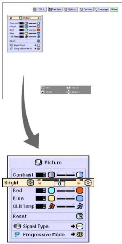
1 Press

•The menu screen is displayed.

Note
- The "Picture" menu screen for the selected input mode is displayed.
- The on-screen display shown on the lower right is displayed when the INPUT 1 or 2 mode is selected.


▼Menu Screen
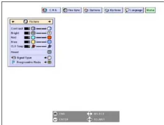
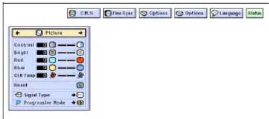
2 Press ◀ or ▶ to select the menu you want to adjust.

Note
- For details on the menus, see the tree charts on pages 40 and 41.
3 Press ▲▲r▼to select the item you want to adjust.

Note
- To display a single adjustment item, press ⏻ after selecting the item. Only the menu bar and the selected adjustment item will be displayed. Then if you press ▲ or ▼, the following item ("Red" is after "Bright") will be displayed.

- Press ☑ to return to the previous screen.
4 Press ◀ or ▶ to adjust the item selected.
•The adjustment is stored.
5
Press

•The menu screen will disappear.

Menu Selections (Settings)
1 Press

•The menu screen is displayed.

Note
- The "Picture" menu screen for the selected input mode is displayed.
- The on-screen display shown on the lower right is displayed when INPUT 1 or 2 mode is selected.
2
Press ◀ or ▶ to select the menu you want to adjust.

Note
- For details on the menus, see the tree charts on pages 40 and 41.
3
Press ▲▲r ▼▼o select the item you want to set.

Note
- Press ⏻ to return to the previous screen.
- In some menus, select the icon using “→”


▼ Menu screen


4
Press

•The cursor shifts to the sub menu.
5
Press ▲▲▼▼ to select the setting of the item displayed in the sub menu.
6
Press

•The item selected is set.

Note
- Some adjustment items will display a confirmation message.
When setting an item, press ◀ or
▶ to select "Yes" or "OK" and then press 📄.
7
Press

•The menu will disappear.


Adjusting the Picture
You can adjust the projector's picture to your preferences with the following picture settings.
| Selected Item | Description | ◀ button ▶ button | |
| Contrast | For adjusting the contrast level | For less contrast | For more contrast |
| Bright | For adjusting the brightness of an image | For less brightness | For more brightness |
| Color | For adjusting the color intensity of the image | For less color intensity | For more color intensity |
| Tint | For adjusting the tones of an image | Skin tones become purplish | Skin tones become greenish |
| Sharp | For making sharper or softer the contour of an image | For less sharpness | For more sharpness |
| Red | For adjusting the redness level | For weaker red | For stronger red |
| Blue | For adjusting the blue level | For weaker blue | For stronger blue |
| CLR Temp | For adjusting the color temperature of an image | Decreases color temperature for warmer, reddish, incandescent-like images. | Increases color temperature for cooler, bluish, fluorescent-like images. |

Picture

C.M.S.

Fine Sync

Options

Options

Language
Sta
Adjusting Image Preferences
Adjust the "Picture" menu on the menu screen.
→For operating the menu screen, see pages 42 to 45.

Note
- "Color", "Tint" and "Sharp" are not displayed when selecting INPUT 1 or 2 and the "Signal Type" is "RGB".
- The picture adjustments can be stored separately in each input mode.
- When the signal type in INPUT 1 or 2 has been set to Component, "Sharp" can be adjusted when 480I, 480P, 540P, 580I, 580P, 720P, 1035I or 1080I signals are connected.
- To reset all adjustment items, select "Reset" and press ⏻.
- "Red", "Blue" and "CLR Temp" cannot be adjusted when "Color Selected" on the C.M.S. menu is set to "sRGB".
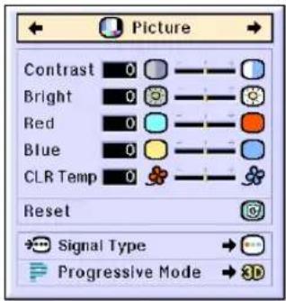
Selecting the Signal Type
This function allows you to select the input signal type RGB or Component for INPUT 1 or 2.
Select "Signal Type" in the "Picture" menu on the menu screen.
→ For operating the menu screen, see pages 42 to 45.

Note
•RGB
Set when RGB signals are received.
- Component
Set when Component signals are received.
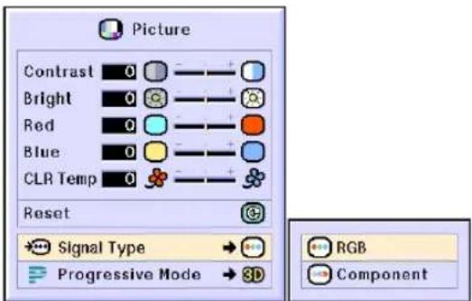
Progressive Mode
This function allows you to select the progressive display of a video signal. The progressive display projects a smoother video image.
Select "Progressive Mode" in the "Picture" menu on the menu screen.
→For operating the menu screen, see pages 42 to 45.

Note
• 2D Progressive
This function is useful to display fast-moving images such as sports and action films. This mode optimizes the image in a displayed frame.
• 3D 3D Progressive
This function is useful to display relatively slow-moving images such as drama and documentary more clearly.
This mode optimizes the image by estimating the movement of a number of preceding and succeeding frames.
• Film Mode
Reproduces the image of film source clearly. Displays the optimized image of film transformed with three-two pull down (NTSC and PAL60Hz) or two-two pull down (PAL50Hz and SECAM) enhancement to progressive mode images.
* The film source is a digital video recording with the original encoded as is at 24 frames/second. The projector can convert this film source to progressive video at 60 frames/second with NTSC and PAL60Hz or at 50 frames/second with PAL50Hz and SECAM to play back a high-definition image.
- When using progressive inputs, these inputs are directly displayed therefore 2D Progressive, 3D Progressive and Film Mode cannot be selected. These modes can be selected in interlace signals other than 1080I.
- In NTSC or PAL60Hz, even if the 3D Progressive mode has been set, the three-two pull down enhancement will be enabled automatically, when the film source has been entered.
- In PAL50Hz or SECAM, the two-two pull down enhancement will be enabled only in the Film Mode, when the film source has been entered.

Adjusting Computer Images
Use the Fine Sync function in case of irregularities such as vertical stripes or flickering in portions of the screen.
| Selected Item Description | |
| Clock | Adjusts vertical noise. |
| Phase | Adjusts horizontal noise (similar to tracking on your VCR). |
| H-Pos | Centers the on-screen image by moving it to the left or right. |
| V-Pos | Centers the on-screen image by moving it up or down. |

Picture

C.M.S.

Fine Sync

Options

Options

Language
Status
Computer Image Adjustment
When "Auto Sync" is set to OFF or when vertical stripes or flickering occur in portions of the screen even if "Auto Sync" is set to "Normal" or "High Speed", adjust "Clock", "Phase", "H-Pos" or "V-Pos" to obtain the best computer image.
Select "Clock", "Phase", "H-Pos" or "V-Pos" in the "Fine Sync" menu on the menu screen.
→ For operating the menu screen, see pages 42 to 45.

Note
- Computer image adjustments can be made easily by pressing AUTO SYNC. See page 50 for details.
Saving Adjustment Settings
This projector allows you to store up to seven adjustment settings for use with various computers.
Select "Save Setting" in the "Fine Sync" menu on the menu screen.
→ For operating the menu screen, see pages 42 to 45.
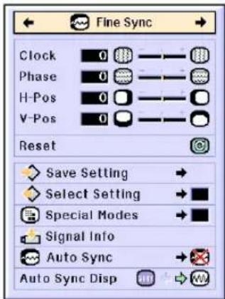

| Resolution | Vert Freq | |
| 1 | 1024 × 768 | 60 Hz |
| 2 | ||
| 3 | ||
| 4 | ||
| 5 | ||
| 6 | ||
| 7 |
Selecting Adjustment Settings
Adjustment settings stored in the projector can be easily accessed.
Select "Select Setting" in the "Fine Sync" menu on the menu screen.
→ For operating the menu screen, see pages 42 to 45.

Note
- If a memory has not been set, a resolution and frequency setting will not be displayed.
- When selecting a stored adjustment setting with "Select Setting", you can set the projector in the stored adjustments.
Special Mode Settings
Ordinarily, the type of input signal is detected and the correct resolution mode is automatically selected. However, for some signals, the optimal resolution mode in "Special Modes" on the "Fine Sync" menu screen may need to be selected to match the computer display mode.
Set the resolution by selecting "Special Modes" in the "Fine Sync" menu on the menu screen.
→ For operating the menu screen, see pages 42 to 45.

Note
- Avoid displaying computer patterns which repeat every other line (horizontal stripes). (Flickering may occur, making the image hard to see.)
- When a DVD player or Digital Video is connected, select 480P as the input signal.
- See "Checking the Input Signal" below for information on the currently selected input signal.
Checking the Input Signal
This function allows you to check the current input signal information.
Select "Signal Info" in the "Fine Sync" menu on the menu screen.
→ For operating the menu screen, see pages 42 to 45.

Note
•The projector will display the number of scanned lines available from audio-visual equipment such as a DVD player or Digital Video.


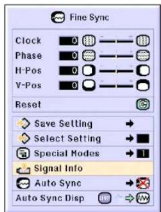

Auto Sync Adjustment
Used to automatically adjust a computer image.
Select "Auto Sync" in the "Fine Sync" menu on the menu screen.
→ For operating the menu screen, see pages 42 to 45.

Note
When setting to "Normal" or
"High Speed":
- Auto Sync adjustment will occur when the projector is turned on or when the inputs are switched, when connected to a computer.
Manual adjustments should be performed:
- When the optimum image cannot be achieved with Auto Sync adjustment. See page 48.
- Auto Sync adjustment may take some time to complete, depending on the image of the computer connected to the projector.
- When setting "Auto Sync" to "OFF" or "High Speed", and if AUTO SYNC is pressed Auto Sync will be executed in "High Speed" mode. If the button is pressed again within one minute, Auto Sync will be executed in "Normal" mode.
Auto Sync Display Function
Used to set the screen displayed during Auto Sync.
Select "Auto Sync Disp" in the "Fine Sync" menu on the menu screen.
→ For operating the menu screen, see pages 42 to 45.

Note
• The image set as a background image is projected.
• ..... The computer image being adjusted is displayed.

Screen display during Auto Sync
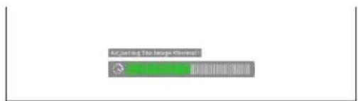

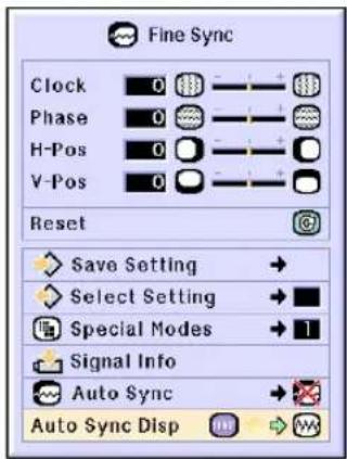
Easy to Use Functions

Selecting the Picture Display Mode
This function allows you to modify or customize the picture display mode to enhance the input image. Depending on the input signal, you can choose “NORMAL”, “FULL”, “DOT BY DOT”, “BORDER”, “STRETCH” or “SMART STRETCH” image.
Switching the Picture Display Using Different Input Signals

•Each time 📊 is pressed, the display changes as shown on page 52 and 53.

Info
- In the Dot by Dot Mode, images are displayed in the original resolution, therefore they will not be enlarged.
- To return to the standard image, press while "RESIZE" is displayed on the screen.

Screen display of the picture display mode

RESIZE
NORMAL
COMPUTER
| NORMAL | FULL | DOT BY DOT | ||
| 4:3 aspect ratio | SVGA (800 × 600) | 1024 × 768 | — | 800 × 600 |
| XGA (1024 × 768) | 1024 × 768 | — | — | |
| SXGA (1280 × 960) | 1024 × 768 | — | 1280 × 960 | |
| UXGA (1600 × 1200) | 1024 × 768 | — | 1600 × 1200 | |
| Other aspect ratios | SXGA (1280 × 1024) | 960 × 768 | 1024 × 768 | 1280 × 1024 |
- "NORMAL" is fixed when XGA (1024 × 768) signals are entered.
| Input Signal | Output screen image | |||
| NORMALProjects a full screen image while maintaining the aspect ratio. | FULLProjects a full screen image while ignoring the aspect ratio. | DOT BY DOTProjects the original resolution signal of the image. | ||
| Resolution lower than XGA |  4:3 aspect ratio 4:3 aspect ratio |  | —— |  |
| XGA |  4:3 aspect ratio 4:3 aspect ratio |  | —— | —— |
| Resolution higher than XGA |  4:3 aspect ratio 4:3 aspect ratio |  | —— |  |
| SXGA (1280 × 1024) |  |  | —— |  |
| NORMAL | FULL | BORDER | STRETCH | SMART STRETCH | ||
| 480I, 480P, 580I, 580P, NTSC, PAL, SECAM | 4:3 aspect ratio. Letter box, squeeze | 1024 × 768 | — | 768 × 576* | 1024 × 576* | 1024 × 576* |
| 540P | 16:9 aspect ratio | — | 1024 × 768 | — | — | |
| 720P, 1035I, 1080I | 16:9 aspect ratio | — | — | — | — | |
- "STRETCH" is fixed when 720P, 1035I or 1080I signals are entered.
* The Digital Shift function can be used with these images.
| Input Signal | Output screen image | |||||
| NORMALProjects a full screen image. | FULLProjects the center part in a 4:3 screen by enlarging 1.3 times toward the horizontal direction. | BORDERProjects 4:3 image fully in STRETCH (the following column) image. | STRETCHProjects 16:9 Image evenly over entire screen (top/bottom black bands). | SMART STRETCHProjects the image fully in a 16:9 screen by enlarging only the surrounding areas while keeping the aspect ratio in the middle part of the image at 4:3. | ||
| 480I, 480P,580I, 580P,NTSC, PAL, SECAM |  4:3 aspect ratio 4:3 aspect ratio | |||||
 Letter box Letter box | ||||||
 Squeeze Squeeze | ||||||
| 540P |  16:9 aspect ratio 16:9 aspect ratio | |||||
 16:9 aspect ratio(4:3 aspect ratio in 16:9 screen) 16:9 aspect ratio(4:3 aspect ratio in 16:9 screen) | ||||||
| 720P, 1035I, 1080I | 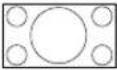 16:9 aspect ratio 16:9 aspect ratio | |||||
Displaying a Still Image
This function allows you to instantly freeze a moving image. This is useful when you want to display a still image from a computer or video, giving you more time to explain the image to the audience.
Freezing a Moving Image
1 Press

•The projected image is frozen.

▼On-screen Display
FREEZE ON
2
FREEZE Press again to return to the moving image from the currently connected device.
FREEZE OFF
Enlarging a Specific Portion of an Image
This function allows you to enlarge a specific portion of an image. This is useful when you want to display a detailed portion of the image.
Displaying an Enlarged Portion of an Image
1 Press

-Enlarges the image.
- Pressing 📄 📆 enlarges or reduces the projected image.

Note

- You can change the location of the enlarged image using ▲, ▼, ◀ and ▶.
- When an image with a resolution higher than SXGA is displayed, “×2” and “×3” cannot be selected.
2
Press Ⓤ to cancel the operation, then the magnification returns to ×1.

Note
In the following cases, the image will return to the normal size ( × 1).
- When switching the INPUT mode.
- When 📋 has been pressed.
- When the input signal is changed.
- When the input signal resolution and refresh rate (vertical frequency) change.
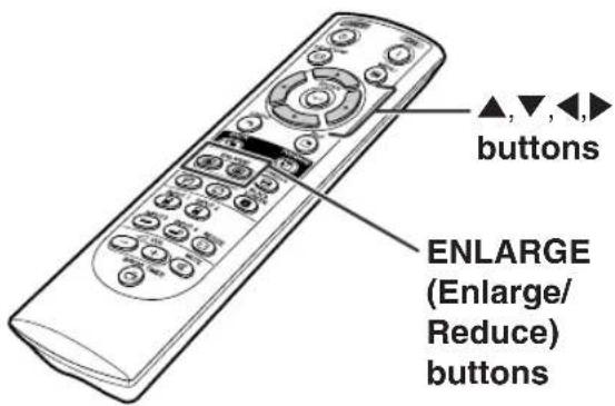
▼On-screen Display


Gamma Correction Function
Gamma is an image quality enhancement function that offers a richer image by brightening the darker portions of the image without altering the brightness of the brighter portions. When you are displaying images with frequent dark scenes, such as a film or concert, or when you are displaying images in a bright room, this feature makes the dark scenes easier to see and gives the impression of greater depth in the image.
| Selected Mode | Description |
| STANDARD | For Standard picture |
| PRESENTATION | Brightens darker portions of image for more enhanced presentations. |
| CINEMA | Gives greater depth to darker portions of image for a more exciting theater experience. |
| CUSTOM | Allows you to adjust gamma value using Sharp Advanced Presentation Software. |
Adjusting Gamma Correction
1 Press

•Each time is pressed, the gamma level toggles between the different types of gamma modes.
2 To return to the default settings, press ⏻ when “GAMMA” is displayed.

Note
- The Gamma mode does not operate for INPUT 1 or INPUT 2 when "Color Selected" on the C.M.S. menu is set to "sRGB".
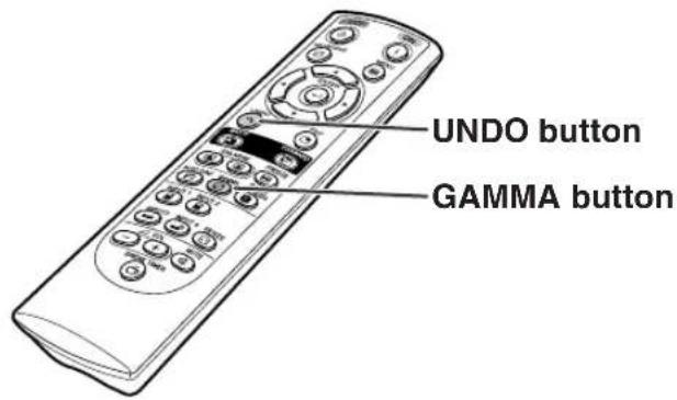
STANDARD CUSTOM

←


PRESENTATION CINEMA
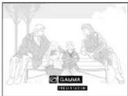
→

Displaying Dual Pictures (Pict in Pict)
Picture in Picture function allows you to display two pictures on the same screen. You can display the image input from INPUT 3 or 4 as an inset picture overlapping the main picture from INPUT 1 or 2.
Displaying the Inset Picture
1 Press

2 Press


control or 📋 on the projector to switch the image in the inset picture.
3 Press


to set the picture.
- Press ⏻ to stop the frame from moving or to make the frame disappear.
4 Press


ove the inset pic-
- The inset picture will be moved to the inset picture frame.

Note
- The inset picture can only be displayed with composite video (NTSC/PAL/SECAM) or S-Video signal.
- The Freeze function works only with the inset picture, when the Pict in Pict mode is in operation.
When the signal entered into INPUT 1 or 2 is as follows, Pict in Pict does not work:
- With a resolution that exceeds SXGA.
- When the input signal is 480I, 480P, 540P, 580I, 580P, 720P, 1035I or 1080I.
- When the input signal has changed to the Interlace mode using RGB signals.
- When the picture display mode is set to "DOT BY DOT".
- When no signals are sent to INPUT 1 or 2, or when the resolution or refresh rate (vertical frequency) is changed.
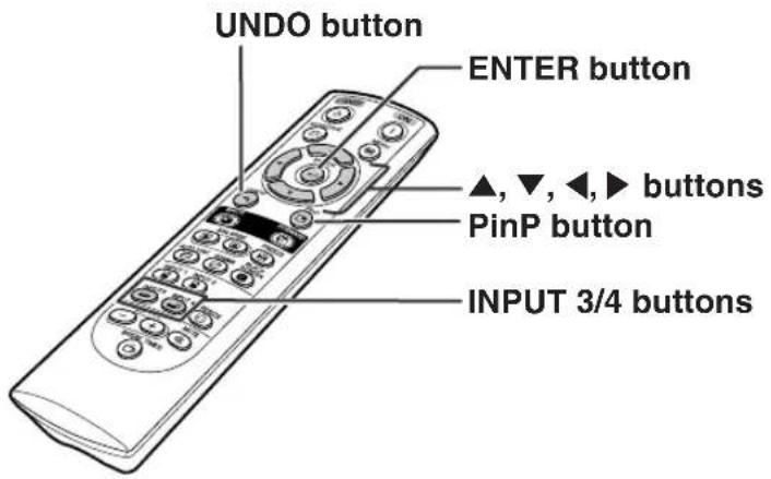
![graph TD A["Presentation slide"] --> B["Pleasebox"] B --> C["Presentation slide"]](/content/2026/08/1623398/images/1c708c5be4861b4ed7a54777d41676bb056e3f7778c1725939c2772ceb21f230.jpg)
This function can be used to display a black screen.
Blacking out the Projected Image
1 Press

- The screen turns black and "BLACK SCREEN" is displayed on the screen.
2 To return to the original projected image, press again.

▼ Projected Image

Displaying the Break Timer
This function can be used to show the remaining time for break during meeting.
Displaying and Setting the Break Timer
1 Press . The break timer starts to count down from 5 minutes.
2 When “💡” is displayed, press ▲▼▼▼ or ▶ to set the break timer.
- You can set anywhere between 1 and 60 minutes (in 1 minute units).
- The break timer starts to count down as soon as ▲, ▼, ◀ or ▶ is pressed.
3 Press UNDO to cancel the break timer.

Note
- Auto Power Off function will be temporarily disabled during the break timer. When no input signal is detected for more than 15 minutes, the projector will automatically enter the standby mode if the break timer has elapsed.
- The break timer will be displayed on the startup image. To change the screen displayed during the break timer, change the setting of "Startup Image" (see page 68).

▼On-screen Display

4:50
Color Management System (C. M. S.)
This function allows you individually adjust the display characteristics of six colors (R: Red, Y: Yellow, G: Green, C: Cyan, B: Blue, M: Magenta).

Picture

C.M.S

Fine Sync

Options

Options

Language
Status
Selecting the Color Reproduction Mode
Select "Color Selected" in the "C.M.S." menu on the menu screen.
→ For operating the menu screen, see pages 42 to 45.

Note
- For additional information about sRGB function, visit "http://www.srgb.com/".
- "sRGB" cannot be selected for "Color Selected" on the C.M.S. menu when "Component" is selected for "Signal Type" on the "Picture" menu.
- When "sRGB" is selected;
•The gamma correction cannot be set.
- "Red", "Blue" or "CLR Temp" in "Picture" cannot be adjusted.
- If "Standard" or "sRGB" is selected for "Color Selected", other items (e.g., Target) cannot be adjusted.

Info
- When "sRGB" is selected, the projected image may become dark; however, this does not indicate a malfunction.
Selecting the Target Color
Select "Target" in the "C.M.S." menu on the menu screen.
→ For operating the menu screen, see pages 42 to 45.
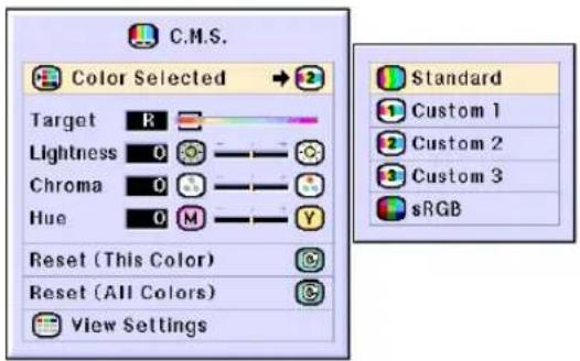
| Selected item | Description |
| Standard | Sharp default setting |
| Custom 1-3 | “Lightness”, “Chroma” and “Hue” can be adjusted for each of the six colors. |
| sRGB | The mode changes to sRGB |

| Red Cyan | ||
| Yellow Blue | ||
| Green Magenta |
Setting the Brightness of the Target Color
Select "Lightness" in the "C.M.S." menu on the menu screen.
→ For operating the menu screen, see pages 42 to 45.

Setting the Chromatic Value of the Target Color
Select "Chroma" in the "C.M.S." menu on the menu screen.
→ For operating the menu screen, see pages 42 to 45.

Setting the Hue of the Target Color
Select "Hue" in the "C.M.S." menu on the menu screen.
→ For operating the menu screen, see pages 42 to 45.
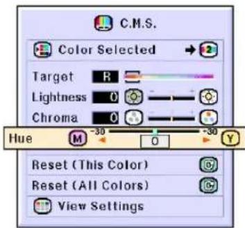
Resetting User-Defined Color Settings
Select "Reset (This Color)" or "Reset (All Colors)" in the "C.M.S." menu on the menu screen.
→ For operating the menu screen, see pages 42 to 45.
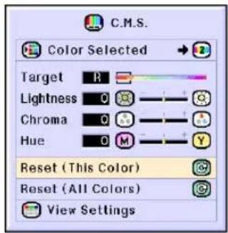
| Selected item | Description |
| Reset (This Color) | “Lightness”, “Chroma” and “Hue” of the color selected for “Target” are reset. |
| Reset (All Colors) | “Lightness”, “Chroma” and “Hue” of all colors are reset. |
Overview of All Color Settings
Select "View Settings" in the "C.M.S." menu on the menu screen.
→ For operating the menu screen, see pages 42 to 45.


Setting the Audio Output Type
This function allows you to set the audio output type.

Picture

C.M.S.

Fine Sync

Options

Options

Language
Status
| Selected Item | Description |
| FAO(Fixed audio output) | Audio output that does not vary in strength with the volume level of the source projector. |
| VAO(Variable audio output) | Audio output that varies in strength with the volume level of the source projector. |
Setting the Audio Output Type
Select "Audio Out" in the "Options (1)" menu on the menu screen.
→ For operating the menu screen, see pages 42 to 45.
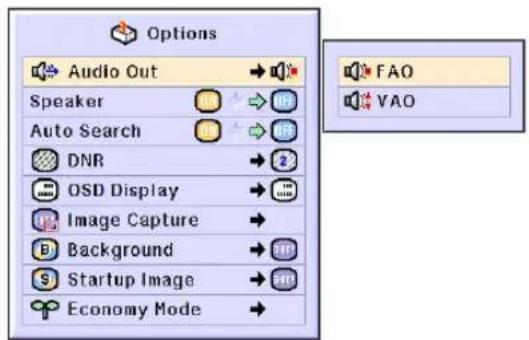
Setting on/off the Internal Speaker
This function allows you to set on/off the internal speaker.
Setting on/off the Internal Speaker
Select "Speaker" in the "Options (1)" menu on the menu screen.
→ For operating the menu screen, see pages 42 to 45.

Auto Search Function
This function automatically searches for and switches to the input mode in which signals are being received, when the projector is turned on, or when the INPUT button is pressed.

Picture

C.M.S.

Fine Sync

Options

Options

Language
Status
Using Auto Search
Select "Auto Search" in the "Options (1)" menu on the menu screen.
→ For operating the menu screen, see pages 42 to 45.

Note

Automatically switches to the input mode in which signals are being received, when turning on the projector or pressing Ⓗ on the projector.

For switching input modes manually in order by pressing ⏻ on the projector.
•To stop searching for the input mode, press 📄 on the projector, or 📄 on the remote control.

Info
- Even while this function is searching for input signals, whenever INPUT 1, INPUT 2, INPUT 3, or
on the remote control is pressed, the but mode is switched to the respective - Even while the function is searching for input signals, pressing Ⓞ on the projector returns to the previous input mode.


Video Digital Noise Reduction (DNR) System
Digital Noise Reduction (DNR) provides high quality images with minimal dot crawl and cross color noise.

Picture

C.M.S

Fine Sync

Options

Options

Language
Status
Reducing Image Noise
Select "DNR" in the "Options (1)" menu on the menu screen.
→ For operating the menu screen, see pages 42 to 45.

Note
- Set a level so as to view a clearer picture.
Make sure to set DNR to "OFF" in the following cases:
- When the image is blurry.
- When the contours and colors of moving images drag.
- When TV broadcasts with weak signals are projected.

Info
- This function is available with INPUT 1, 2 (480I, 480P, 580I and 580P signals) and INPUT 3, 4 (all signals).
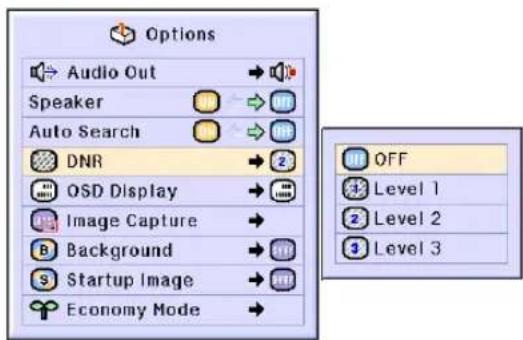
Setting On-screen Display
This function allows you to turn on or off the on-screen messages. When setting “Level A” or “Level B” in “OSD Display”, the input mode display (e.g. INPUT 1) will not appear, even if the INPUT button is pressed.
| Selected Item | Description |
| Normal | All On-screen Displays are displayed. |
| Level A | Input/Freeze/Enlarge/Auto Sync/Volume/Mute/Black Screen are not displayed. |
| Level B | All On-screen Displays are not displayed.(except Menu, On-Screen Displays displayed when the KEYSTONE button is pressed, and warning displays (Temp./Change The Lamp., etc.)) |
Turning Off the On-screen Display
Select "OSD Display" in the "Options (1)" menu on the menu screen.
→ For operating the menu screen, see pages 42 to 45.

Setting the Video System
The video input system mode is preset to "Auto"; however, a clear picture from the connected audio-visual equipment may not be received, depending on the video signal difference. In that case, switch the video signal.

Picture

C.M.S.

Options

Options

Language
Status
Setting the Video System
Select "Video System" in the "Options (1)" menu on the menu screen.
→ For operating the menu screen, see pages 42 to 45.

Note
- The video signal can only be set in INPUT 3 or INPUT 4 mode.
- In "Auto", images are displayed in PAL even if PAL-N or PAL-M input signals are received.

| PAL | When connected to PAL video equipment. |
| SECAM | When connected to SECAM video equipment. |
| NTSC4.43 | When reproducing NTSC signals in PAL video equipment. |
| NTSC3.58 | When connected to NTSC video equipment. |
Saving Projected Images
- This projector allows you to capture projected images (RGB signals) and set them as a startup image, or background image when no signals are being received.
- You can capture the images that are input using RGB signals.




Capturing the Image
Select "Image Capture" in the "Options (1)" menu on the menu screen.
→ For operating the menu screen, see pages 42 to 45.
1
Press ▲▲or ▼▼to select
"Save Image" and press
- The projected image is captured. It may take some time for capturing.
2
①Press ◀ or ▶ to select "Yes".
②Press ENTER.

Note
- Only images from XGA (1024 × 768) non-interlace signals in INPUT 1 or INPUT 2 mode can be captured.
• The saved image is reduced to 256 colors. - Images from equipment connected to INPUT 3 or INPUT 4 terminal cannot be captured.
- Only one image can be captured and saved.
- The color of images may differ before and after saving if an image is captured on which image adjustment has been performed using the "C.M.S." function.


Deleting the Captured Image
1
Select "Delete" and press

2
① Press ◀ or ▶ to select "OK".
② Press ENTER.
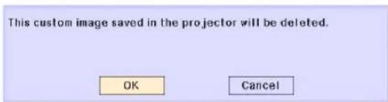
Setting a Background Image
This function allows you to select the image displayed when no signal is being sent to the projector.
| Selected Item | Description |
| Sharp | SHARP default image |
| Custom *1 | User customized image (e.g. company logo) |
| Blue | Blue screen |
| None | Black screen *2 |
*1 You can set a captured image as a background image by selecting "Custom".
*2 If the input signal has interference, the screen will be displayed with the interference.

Picture

C.M.S

Fine Sync

Options

Options

Language
Status
Selecting a Background Image
Select "Background" in the "Options (1)" menu on the menu screen.
→ For operating the menu screen, see pages 42 to 45.

Note
- When "Custom" is selected, an image saved using "Image Capture" can be displayed as a background image.
- A "Custom" image is preset as a black screen.


Selecting a Startup Image
This function allows you to specify the image to be displayed upon the projector's startup.
| Selected Item | Description |
| Sharp | SHARP default image |
| Custom * | User customized image (e.g. company logo) |
| None | Black screen |
* You can set a captured image as a startup image by selecting "Custom".
Selecting a Startup Image
Select "Startup Image" in the "Options (1)" menu on the menu screen.
→ For operating the menu screen, see pages 42 to 45.

Note
- When "Custom" is selected, an image saved using "Image Capture" can be displayed as a startup image.
- A "Custom" image is preset as a black screen.

Selecting the Economy Mode
These functions allow you to reduce the power consumption of the projector.



Setting the Power Save Mode
Select "Power Save" in "Economy Mode" under the "Options (1)" menu on the menu screen.
→ For operating the menu screen, see pages 42 to 45.

Note
- Although lamp life and noise are improved when "Power Save" is set to "ON", brightness decreases by 20%.
- "Power Save" mode is factory preset to "OFF".
Monitor Out/RS-232C Off Function
This projector consumes power when using a monitor connected to the OUTPUT (INPUT 1, 2) terminal and a computer connected to the RS-232C terminal. When not using these terminals, "Mntr.out/RS232" can be set to "OFF" to reduce standby power consumption.
Select "Mntr.out/RS232" in "Economy Mode" under the "Options (1)" menu on the menu screen.
→ For operating the menu screen, see pages 42 to 45.
| ON | Monitor Out/RS-232C connection is set to “ON”. |
| OFF | Monitor Out/RS-232C connection is set to “OFF”. |

Note
- Set "Mntr.out/RS232" to "ON" when using the Sharp Advanced Presentation Software.

| Status | Brightness | Power consumption (When using AC 100V) | Lamp Life |
| ON (Low power mode) | 80% | 325 W | 3,000 hours |
| OFF (Standard mode) | 100% | 400 W | 2,000 hours |

Auto Power Off Function
When no input signal is detected for more than 15 minutes, the projector will automatically enter the standby mode if set to "ON".
The Auto Power Off function will be disabled when it has been set to "OFF".
Select "Auto Power Off" in "Economy Mode" under the "Options (1)" menu on the menu screen.
→ For operating the menu screen, see pages 42 to 45.

Note
- When the Auto Power Off function is set to "ON", 5 minutes before the projector enters the standby mode, the message "Enter STANDBY mode in X min." will appear on the screen to indicate the remaining minutes.
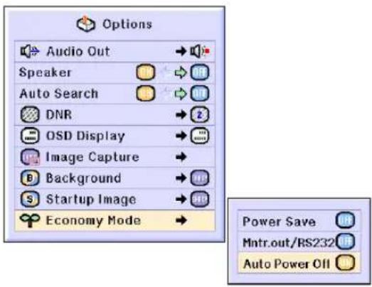
Enter STANDBY mode in 1 min.

Displaying the Remaining Lamp Life (Percentage)

Picture

C.M.S.

Fine Sync

Options

Options

Language
Status
Checking the Remaining Lamp Life (Percentage)
This function allows you to check the remaining lamp life (percentage).
Select the "Options (2)" menu on the menu screen.
→ For operating the menu screen, see pages 42 to 45.

Note
- It is recommended that the lamp be changed when the remaining lamp life becomes 5%.
For lamp replacement, contact your nearest Sharp Authorized Projector Dealer or Service Center. - The table at the right indicates rough estimates in the case of using only in each mode shown. Remaining lamp life changes within the range of the values shown depending on the frequency at which "Power Save" is switched "ON" and "OFF" (see page 69).
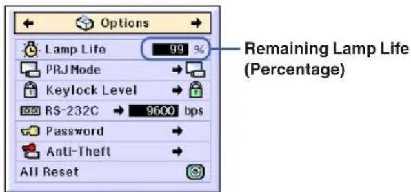
| Remaining lamp life | ||
| 100% 5% | ||
| Used with only “ON” on “Power Save” (Low power mode) | 3,000 hours | 150 hours |
| Used with only “OFF” on “Power Save” (Standard mode) | 2,000 hours | 100 hours |
Reversing/Inverting Projected Images
This projector is equipped with a reverse/invert image function that allows you to reverse or invert the projected image for various applications.
| Selected Item | Description |
| Front | Normal image |
| Ceiling + Front | Inverted image |
| Rear | Reversed image |
| Ceiling + Rear | Reversed and inverted image |

Picture

C.M.S.

Fine Sync

Options

Options

Language
Status
Setting the Projection Mode
Select "PRJ Mode" in the "Options (2)" menu on the menu screen.
→ For operating the menu screen, see pages 42 to 45.

Note
- If a password has been set, the password input box will be displayed when selecting the "PRJ Mode".
- This function is used for the reversed image and ceiling-mount setups. See page 32 for these setups.

Front Ceiling+Front Rear Ceiling+Rear
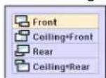
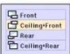
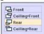



Locking the Operation Buttons on the Projector
This function can be used to lock the use of certain operation buttons on the projector. The following are the three keylock levels.
| Keylock Level | Description |
| Normal | All operation buttons are functional. |
| Level A | Only INPUT/VOLUME buttons on the projector are available. |
| Level B | All operation buttons on the projector are unavailable. |
Setting up the Keylock
Select "Keylock Level" in the "Options (2)" menu on the menu screen.
→ For operating the menu screen, see pages 42 to 45.

Note
- If a password has been set, the password input box will be displayed when selecting the "Keylock Level".

Canceling the Keylock Setting
When the Keylock Level is set to "Normal", all buttons are functional.
Select "Keylock Level" in the "Options (2)" menu on the menu screen and set "Normal".
→ For operating the menu screen, see pages 42 to 45.

Note
- When a password has been set, and "Keylock Level" is selected, the password input box will be displayed.
- If both a password and the Keylock Level have been set at the same time, the password will be necessary before changing the Keylock Level.
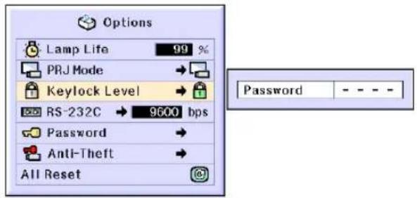
Selecting the Transmission Speed (RS-232C)
This menu allows you to adjust the transmission speed of the RS-232C connection by selecting the baud rate.

Picture

C.M.S.

Fine Sync

Options

Options

Language
Status
Selecting the Transmission Speed (RS-232C)
Select "RS-232C" in the "Options (2)" menu on the menu screen.
→ For operating the menu screen, see pages 42 to 45.

Note
- When a password has been set, and "RS-232C" is selected, the password input box will be displayed.
- Make sure that both the projector and computer are set for the same baud rate. Refer to the computer's operation manual for instructions for setting the computer's baud rate.
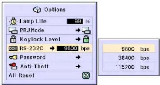
Setting up a Password
A password can be set by the user to prevent adjustments to certain settings on the “Options (2)” menu. Using a password together with the Keylock Level (page 71) is more effective.

Picture

C.M.S.

Fine Sync

Options

Options

Language
Status
Entering the Password
Select "Password" in the "Options (2)" menu on the menu screen.
→ For operating the menu screen, see pages 42 to 45.
1
Press ▲▲r ▼▼o select the desired number and then press ▶.
2
Enter the 3 remaining digits and press ENTER.
3
Enter the password again in "Reconfirm" and press ENTER.

Note
- When a password is set, you need to enter the password to change "PRJ Mode", "Keylock Level", "RS-232C", "Anti-Theft" and "All Reset" settings.


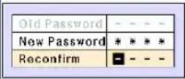
Changing the Password
Select "Password" in the "Options (2)" menu on the menu screen.
→ For operating the menu screen, see pages 42 to 45.
1 Press ▲, ▼ and ▶ to enter the password in "Old Password" and press ENTER.
2 Press ▲,▼ and ▶ to set the new password and press ENTER.
3 Enter the new 4-digit password again in “Reconfirm” and press ENTER.

Note
- If you do not want to set a password, leave the fields in procedures 2 and 3 blank and press 📄.
- To cancel the password settings, click 📋.
If You Forget Your Password
If you forget the password, delete it and set a new password using the following procedure.
![graph LR A["Press"] --> B["ON ON"] B --> C["ENTER"] C --> D["O"] D --> E["ENTER"] E --> F["O"] F --> G["Menu"]](/content/2026/08/1623398/images/86fe4268abfd9db0b0a91eb60e1a775bcc3d60d960b6bb3981aa8b51e9f9323d.jpg)


Setting the Anti-Theft
The anti-theft function prevents unauthorized use of the projector. You can choose to use this function or not. If you do not want to use this function, just do not enter the keycode. Once the anti-theft function is activated, users will need to enter the correct keycode each time the projector is turned on. Failure to enter the correct keycode will cause images not to be projected. The following procedures explain how to use this function.

Picture

C.M.S.

Fine Sync

Options

Options

Language
Status
Entering the Keycode
- "Anti-Theft" cannot be selected unless "Password" is set. (See page 73.)
- When "Anti-Theft" is selected, the password input box will appear. Enter the keycode after the right password is entered.
Select "Anti-Theft" in the "Options (2)" menu on the menu screen.
→ For operating the menu screen, see pages 42 to 45.

Info
- Once the function is activated, you must remember the correct keycode. We suggest you record the keycode in a safe place where only authorized users have access. If you lose or forget your keycode, you will need to contact your nearest Sharp Authorized Projector Dealer or Service Center (see page 96). You may need to bring your projector to them to restore the projector to original factory condition (password and keycode reset).
1 Press any button you like on the remote control or projector to set the first digit in "New Code".

Note
- The following buttons on the remote control and projector cannot be set as keycodes:
-ON button
•STANDBY button
- ENTER button
- UNDO button
- MENU button
•FORWARD button
- BACK button


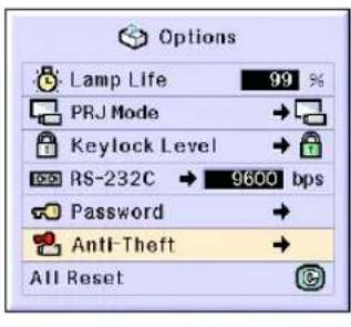

2 Enter the remaining 3 digits by pressing any buttons you like.
3 Enter the same keycode once more in "Reconfirm".

•The Keylock function will become temporarily disabled.
When "Anti-Theft" is set, the keycode inputting box appears after the power is turned on. When it appears, enter the right keycode.
- Press the buttons on the remote control if the buttons on the remote control are used for setting the keycode. In the same manner, press the buttons on the projector if the buttons on the projector are used for setting the keycode.
Changing the Keycode
- When "Anti-Theft" is selected, the password input box is displayed. After the password has been entered, you can change the keycode. Select "Anti-Theft" in the "Options (2)" menu on the menu screen. → For operating the menu screen, see pages 42 to 45.
1 Press the buttons on the remote control or the projector to enter the preset 4-digit keycode in "Old Code".
2 Press any button you like on the remote control or the projector to enter the new keycode.
3 Enter the same 4-digit keycode in "Reconfirm".

Note
- If you do not want to set a keycode, leave the keycode field blank in steps 2 and 3 and press 📄.
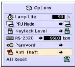
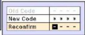


Initializing the Settings
This function allows you to initialize the settings you have made in the projector.

Picture

C.M.S.

Fine Sync

Options

Options

Language
Status
Returning to the Default Settings
Select "All Reset" in the "Options (2)" menu on the menu screen.
→ For operating the menu screen, see pages 42 to 45.

Note
- If a password has been set, the password input box will be displayed when selecting "All Reset".
The following items cannot be initialized.
•C. M. S.
- "Lightness", "Chroma" and "Hue" respectively saved for Custom 1-3 on the C.M.S. menu.
•Fine Sync
•Special Modes
•Signal Info
-Options
•Lamp Life
•Anti-Theft
•Language
- Image stored using "Image Capture"

Displaying the Adjustment Settings
This function can be used to display all the adjusted settings as a list on the screen.


Overview of All Menu Settings
Select the "Status" menu on the menu screen and press ENTER.
→ For operating the menu screen, see pages 42 to 45.
| Picture | C.M.S. | Fine Sync | Options | Options | Other |
| 90% | English | ||||
| Contrast | Color Selected | Clock | Audio Out | Lamp Life | Language |
| PRJ Mode | |||||
| Bright | Phase | Speaker | |||
| H-Pos | Auto Search | Keylock Level | |||
| Red | 115200bps | Standard | |||
| V Pos | DNR | RS 232C | Gamma | ||
| Blue | |||||
| Select Setting | OSO Display | Password | Normal | ||
| CLR Topp | Resize | ||||
| Special Modes | Background | Anti Theft | |||
| Signal Type | Auto Sync | Startup Image | |||
| Auto Sync Disp | Power Save | Serial Number | |||
| Radioout/RS232 | Auto Power Off | Firmware |
Appendix
Maintenance
Cleaning the projector
■Be sure to unplug the power cord before cleaning the projector.
■The cabinet as well as the operation panel is made of plastic. Avoid using benzene or thinner, as these can damage the finish on the cabinet.
■Do not use volatile agents such as insecticides on the projector.
Do not attach rubber or plastic items on the projector for long time.
The effects of some of the agents in the plastic may cause damage to the quality or finish of the projector.

■Wipe off dirt gently with a soft flannel cloth.

■When the dirt is hard to remove, soak a cloth in a neutral detergent diluted with water, wring the cloth well and then wipe the projector.
Strong cleaning detergents may discolor, warp or damage the coating on the projector.
Make sure to test on a small, inconspicuous area on the projector before using.
Cleaning the lens
■Use a commercially available blower or lens cleaning paper (for glasses and camera lenses) for cleaning the lens. Do not use any liquid type cleaning agents, as they may wear off the coating film on the surface of the lens.
■As the surface of the lens can easily get damaged, be sure not to scrape or hit the lens.
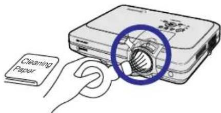
Cleaning the exhaust and intake vents
■Use a vacuum cleaner to clean dust from the exhaust vent and the intake vent.
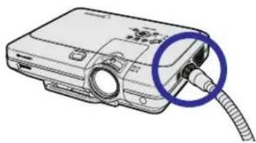
Replacing the Air Filter
- This projector is equipped with air filters to ensure the optimal operating condition of the projector.
- The air filters should be cleaned every 100 hours of use. Clean the filters more often when the projector is used in a dusty or smoky location.
- Ask your nearest Sharp Authorized Projector Dealer or Service Center to exchange the filter (PFILDA005WJZZ) when it is no longer possible to clean.
Cleaning and replacing the bottom air filter
1
Press STANDBY on the projector or on the remote control to put the projector into the standby mode.
- Wait until the cooling fan stops.
2
Disconnect the power cord.
- Unplug the power cord from the AC socket.
3
Remove the bottom filter cover.
- Turn over the projector. Grab the tab and slide open the filter cover in the direction of the arrow.
4
Remove the air filter.
- Pick the air filter up with your fingers and lift it out of the filter cover.

Air filter (not removable) Air filter
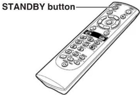


Replacing the Air Filter
5 Clean the air filter.
- Clean the dust off the air filter and cover with a vacuum cleaner extension hose.
6 Replace the air filter.
- Place the air filter underneath the tabs on the filter cover.
7 Replace the filter cover.
- Slide the filter cover in the direction of the arrow to close it.

Note
- Be sure the filter cover is securely installed. The power will not turn on unless it is correctly installed.
- If dust or dirt has collected inside the bottom air filter (not removable), clean the filter with a vacuum cleaner extension hose.

Maintenance Indicators
■The warning lights on the projector indicate problems inside the projector.
If a problem occurs, either the temperature warning indicator or the lamp indicator will illuminate red, and the projector will enter the standby mode. After the projector has entered the standby mode, follow the procedures given below.

About the temperature warning indicator
If the temperature inside the projector increases, due to blockage of the air vents, or the setting location, "TEMP." will blink in the lower left corner of the picture. If the temperature keeps on rising, the lamp will turn off and the temperature warning indicator will blink, the cooling fan will run for further 90 seconds, then the projector will enter the standby mode. After "TEMP." appears, be sure to perform the following measures.

About the lamp indicator

Change The Lamp.
■The lamp life becomes 0%, when used for approximately 3,000 hours with "ON" in "Power Save" or when used for approximately 2,000 hours with "OFF" in "Power Save" (see page 69).
When the remaining lamp life becomes 5% or less, “☒” will be displayed on the screen in yellow. When the percentage becomes 0%, “☒” will change to “☒ (red), the lamp will automatically turn off and then the projector will automatically enter the standby mode. At this time, the lamp indicator will illuminate in red.
If you try to turn on the projector a fourth time without replacing the lamp, the projector will not turn on.
| Maintenance indicator Condition | Problem Possible Solution | ||||
| Temperature warning indicator | Normal | Abnormal | The internal temperature is abnormally high. | • Blocked air intake | • Relocate the projector to an area with proper ventilation. |
| Off | Red on/ Standby | • Cooling fan break-down• Internal circuit failure• Clogged air intake | • Take the projector to your nearest Sharp Authorized Projector Dealer or Service Center (see page 96) for repair. | ||
| Lamp indicator | Green on Green blinks when the lamp is warming up or shutting down. | Red blinks/ Red on | Time to change the lamp | • Remaining lamp life becomes 5% or under. | • Carefully replace the lamp. (See page 86)• Take the projector to your nearest Sharp Authorized Projector Dealer or Service Center (see page 96) for repair.• Please exercise care when replacing the lamp. |
| Red on/ Standby | The lamp does not illuminate. | • Burnt-out lamp• Lamp circuit failure | |||
| Power indicator | Green on/ Red on | Red blinks | The power indicator blinks in red when the projector is on. | • The filter cover, lamp unit cover or lens cover is open. | • Securely install the covers.• If the power indicator blinks even when the filter cover is securely installed, contact your nearest Sharp Authorized Projector Dealer or Service Center for advice. |
Maintenance Indicators

Info
- If the temperature warning indicator illuminates, and the projector enters the standby mode, follow the possible solutions on the previous page and then wait until the projector has cooled down completely before plugging in the power cord and turning the power back on. (At least 5 minutes.)
- If the power is turned off for a brief moment due to power outage or some other cause while using the projector, and the power supply recovers immediately after that, the lamp indicator will illuminate in red and the lamp may not be lit. In this case, unplug the power cord from the AC outlet, replace the power cord in the AC outlet and then turn the power on again.
- If you want to clean the air vents during projector operation, be sure to put the projector into the standby mode. After the cooling fan has stopped, clean the vents.
- Do not unplug the power cord after the projector has entered the standby mode and while the cooling fan is running. The cooling fan runs for about 90 seconds.
Regarding the Lamp
Lamp
It is recommended that the lamp (sold separately) be replaced when the remaining lamp life becomes 5% or less, or when you notice a significant deterioration in the picture and color quality. The lamp life (percentage) can be checked with the on-screen display. See page 70.
■ For lamp replacement, please consult your nearest Sharp Authorized Projector Dealer or Service Center.
IMPORTANT NOTE TO U.S. CUSTOMERS:
The lamp included with this projector is backed by a 90-day parts and labor limited warranty. All service of this projector under warranty, including lamp replacement, must be obtained through a Sharp Authorized Projector Dealer or Service Center. For the name of the nearest Sharp Authorized Projector Dealer or Service Center, please call toll-free: 1-888-GO-SHARP (1-888-467-4277). U.S.A. ONLY
Caution Concerning the Lamp
This projector utilizes a pressurized mercury lamp. A loud sound may indicate lamp failure. Lamp failure can be attributed to numerous sources such as: excessive shock, improper cooling, surface scratches or deterioration of the lamp due to a lapse of usage time. The period of time up to failure largely varies depending on the individual lamp and/or the condition and the frequency of use. It is important to note that failure can often result in the bulb cracking.
■ When the lamp indicator and on-screen display icon are illuminated or flash, it is recommended that the lamp be replaced with a new one immediately, even if the lamp appears to be operating normally.
■ Should the lamp break, the glass particles may spread inside the lamp cage or gas contained in the lamp may be vented into the room from the exhaust vent. Because the gas in this lamp includes mercury, ventilate the room well if the lamp breaks and avoid all exposure to the released gas. In case of exposure to the gas, consult with a doctor as soon as possible.
■ Should the lamp break, there is also a possibility that glass particles may spread inside of the projector. In such a case, it is recommended you contact your nearest Sharp Authorized Projector Dealer or Service Center to remove the damaged lamp and assure safe operation.
Replacing the Lamp

Caution
- Do not remove the lamp unit immediately after operation of the projector. The lamp will be hot and touching it can lead to burn or injury.
- Wait at least one hour after the power cord is disconnected to allow the surface of the lamp unit to fully cool before removing the lamp unit.
If the new lamp does not light after replacement, take your projector to the nearest Sharp Authorized Projector Dealer or Service Center for repair. Purchase a replacement lamp unit of type BQC-XGC55X//1 from your nearest Sharp Authorized Projector Dealer or Service Center. Then carefully change the lamp by following the instructions described in this section. If you wish, you may have the lamp replaced at your nearest Sharp Authorized Projector Dealer or Service Center.
Removing and Install- ing the Lamp Unit

Info
- Be sure to remove the lamp unit by the handle. Be sure not to touch the glass surface of the lamp unit or the inside of the projector.
•To avoid injury to yourself and damage to the lamp, be sure to carefully follow the steps below. - Do not loosen other screws except for the lamp unit cover and lamp unit. (Only the silver screws are loosened).
- Please refer to the installation manual included with the lamp unit.
1
Press STANDBY on the projector or on the remote control to put the projector into the standby mode.
- Wait until the cooling fan stops.

Warning!
- Do not remove the lamp unit from the projector right after use. The lamp will be very hot and may cause burn or injury.
2
Disconnect the power cord.
- Unplug the power cord from the AC socket.
- Leave the lamp until it has fully cooled down (about 1 hour).
3
Change the air filter.
- Change the air filter whenever you install the lamp unit (see pages 81 and 82).
4
Remove the lamp unit cover.
- Loosen the user service screw that secures the lamp unit cover. Then open the cover in the direction of the arrow.
Lamp unit

BQC-XGC55X//1
STANDBY button


STANDBY button

User service screw


5
Remove the lamp unit.
- Loosen the securing screws from the lamp unit. Hold the lamp unit by the handle and pull it in the direction of the arrow.
6
Insert the new lamp unit.
- Press the lamp unit firmly into the lamp unit compartment. Fasten the securing screws.
7
Attach the lamp unit cover.
- Insert the tab of the lamp unit cover into the opening, and press the cover until it clicks in place.

Info
- If the lamp unit and lamp cover are not correctly installed, the power will not turn on, even if the power cord is connected to the projector.
Resetting the Lamp Timer
Reset the lamp timer after replacing the lamp.
1
Connect the power cord.
- Plug the power cord into the AC socket of the projector.
2
Reset the lamp timer.
- While pressing simultaneously Ⓗ, ⚫ and Ⓦ on the projector, press ⏻ on the projector.
- "LAMP 100%" is displayed, indicating that the lamp timer is reset.

Info
- Make sure to reset the lamp timer only when replacing the lamp. If you reset the lamp timer and continue to use the same lamp, this may cause the lamp to become damaged or explode.
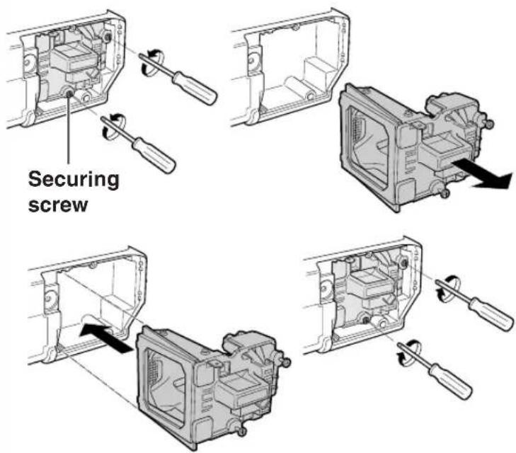
User service screw
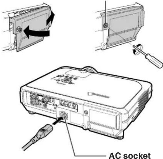
INPUT button ENTER button

Connecting Pin Assignments
INPUT 1/2 RGB and OUTPUT Signal Terminal: 15-pin Mini D-sub female connector
| RGB Input | Component Input |
| 1. Video input (red) | PR ( CR ) |
| 2. Video input (green/sync on green) | Y |
| 3. Video input (blue) | PB ( CB ) |
| 4. Reserve input 1 | Not connected |
| 5. Not connected | Not connected |
| 6. Earth (red) | Earth (Pr) |
| 7. Earth (green/sync on green) | Earth (Y) |
| 8. Earth (blue) | Earth (Pb) |
| 9. Not connected | Not connected |
| 10. GND | Not connected |
| 11. GND | Not connected |
| 12. Bi-directional data | Not connected |
| 13. Horizontal sync (Composite sync) | Not connected |
| 14. Vertical sync signal | Not connected |
| 15. Data clock | Not connected |
RS-232C Terminal: 9-pin Mini DIN female connector

Pin No. Signal Name I/O Reference
1 Output Not connected
2 RD Receive Data Input Connected to internal circuit
3 SD Send Data Output Connected to internal circuit
4 Input Not connected
5 SG Signal Ground Connected to internal circuit
6 Input Not connected
7 RS Output Connected to Pin 8
8 CS Input Connected to Pin 7
9
Output Not connected
9-pin D-sub male connector of the DIN-D-sub RS-232C adaptor
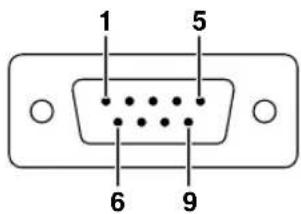
Pin No. Signal Name I/O Reference
1 CD Not connected
2 RD Receive Data Input Connected to internal circuit
3 SD Send Data Output Connected to internal circuit
4 ER Not connected
5 SG Signal Ground Connected to internal circuit
6 Not connected
7 RS Connected to internal circuit
8 CS Connected to internal circuit
9 CI Not connected

Note
- Pin 8(CS) and Pin 7(RS) are short circuited inside the projector.
RS-232C Cable recommended connection: 9-pin D-sub female connector

| Pin No. | Signal | Pin No. | Signal |
| 1 | CD | 1 | CD |
| 2 | RD | 2 | RD |
| 3 | SD | 3 | SD |
| 4 | ER | 4 | ER |
| 5 | SG | 5 | SG |
| 6 | DR | 6 | DR |
| 7 | RS | 7 | RS |
| 8 | CS | 8 | CS |
| 9 | CI | 9 | CI |

Note
- Depending on the controlling device used, it may be necessary to connect Pin 4 and Pin 6 on the controlling device (e.g. PC).

(RS-232C) Specifications and Command Settings
PC control
A computer can be used to control the projector by connecting an RS-232C serial control cable (cross type, sold separately) to the projector. (See page 22 for connection.)
Communication conditions
Set the serial port settings of the computer to match that of the table.
Signal format: Conforms to RS-232C standard. Parity bit: None
Baud rate: 9,600 bps Stop bit: 1 bit
Data length: 8 bits Flow control: None
Basic format
Commands from the computer are sent in the following order: command, parameter, and return code. After the projector processes the command from the computer, it sends a response code to the computer.
Command format
| C1 | C2 | C3 | C4 | P1 | P2 | P3 | P4 |
| Return code (0DH) |
Command 4-digit Parameter 4-digit
Response code format
Normal response
| O | KE |
ReturRcode (0DH)
Problem response (communication error or incorrect command)
Return code (0DH)

Info
- When more than one code is being sent, send each command only after the response code for the previous command from the projector is verified.
- To conserve power in STANDBY mode, the CPU in this model will enter Deep Sleep mode approximately 10 seconds after the last command is received. In the case of transmitting commands during Deep Sleep mode, it takes a maximum of 30 seconds until the response code is received. If subsequent commands are sent to the projector within 10 seconds, the projector will reply immediately. If no further commands are received within 10 seconds, the projector will again return to Deep Sleep mode. Please note that Deep Sleep mode is only activated in STANDBY mode. There is no delayed RS-232C response when the projector is in operation.
- Special commands, "POWR?????" and "TLPS__1" are available for applications that require continuous polling. These commands will not wake the CPU in Deep Sleep mode and the projector will provide immediate reply in STANDBY mode. "1" will indicate Power on, "0" will indicate STANDBY mode. When the power is turned on during standby with the "POWER ON" command, wait for at least 40 seconds after the power has been turned on, and then transmit the next command.
- We suggest disabling the AUTO SEARCH feature before initiating RS-232C communications. If AUTO SEARCH is enabled, it will be necessary to send the STANDBY mode command "POWR__0" two times to power down the projector. (The first "POWR__0" command cancels AUTO SEARCH and the second "POWR__0" command will put the projector into the standby mode.)

Note
- Do not repeatedly or periodically send any commands other than "POWR?????" and "TLPS____1" in STANDBY mode as it will cause problems.
- When the projector is put into the standby mode, a message "Shutting Down. Please Wait." is displayed for about 20 seconds. At that time, if the "POWR__1" command is being sent, "ERR" will be returned and this command is not received.
- When using the computer control function of the projector, the adjustment values cannot be read by the computer. Therefore, confirm the values by transmitting the display commands (e.g. "RARE__0") for each adjustment menu and checking the values with the on-screen display. If the projector receives adjustment/setting commands other than menu display commands, it will execute the commands without displaying the on-screen display.
Commands
Example:
- When "BRIGHT" of INPUT 1 image adjustment is set to -10.
| R | A | B | R | 1 | 0 | _ | ◀|− |
| CONTROL CONTENTS | COMMAND | PARAMETER | RETURN | ||||||
| POWER ON | P | D | W | R | — | — | — | 1 | OK OR ERR |
| STANDBY | P | D | W | R | — | — | — | 0 | OK OR ERR |
| POWER STATUS | P | D | W | R | ? | ? | ? | ? | 0:OFF, 1:ON |
| LAMP POWER STATUS | T | P | O | W | — | — | — | 1 | 0:OFF, 1:ON, 2:COOLING3:SHUTTING DOWN |
| VOLUME (0 - 60) | V | O | L | A | — | — | * | * | OK OR ERR |
| MUTE ON | M | U | T | E | — | — | — | 1 | OK OR ERR |
| MUTE OFF | M | U | T | E | — | — | — | 0 | OK OR ERR |
| KEYSTONE (-127 - +127) | K | E | Y | S | * | * | * | * | OK OR ERR |
| DIGITAL SHIFT (-95 - +96) | L | N | D | S | — | * | * | * | OK OR ERR |
ProjectorComputer
| O | K |
| CONTROLS CONTENTS | COMMAND | PARAMETER | RETURN | |||||||
| BUTTONS & REMOTE CONTROL KEY | BLACK SCREEN ON | I | M | B | K | — | — | — | 1 | OK OR ERR |
| BLACK SCREEN OFF | I | M | B | K | — | — | — | 0 | OK OR ERR | |
| INPUT 1 | I | R | G | B | — | — | — | 1 | OK OR ERR | |
| INPUT 2 | I | R | G | B | — | — | — | 2 | OK OR ERR | |
| INPUT 3 | I | V | E | D | — | — | — | 1 | OK OR ERR | |
| INPUT 4 | I | V | E | D | — | — | — | 2 | OK OR ERR | |
| INPUT CHECK | I | C | H | K | — | — | — | 0 | OK OR ERR | |
| FREEZE ON | F | R | E | Z | — | — | — | 1 | OK OR ERR | |
| FREEZE OFF | F | R | E | Z | — | — | — | 0 | OK OR ERR | |
| AUTO SYNC START | A | D | J | S | — | 1 | OK OR ERR | |||
| CONTROL CONTENTS | COMMAND | PARAMETER | RETURN CONTROL | |||||||
| BUTTONS & REMOTE CONTROL KEYPICTURE | INPUT 1 RESIZE : NORMAL | R | A | S | R | - | - | - | 1 | OK OR ERR |
| INPUT 1 RESIZE : FULL | R | A | S | R | - | - | - | 5 | OK OR ERR | |
| INPUT 1 RESIZE : DOT BY DOT | R | A | S | R | - | - | - | 3 | OK OR ERR | |
| INPUT 1 RESIZE : STRETCH | R | A | S | R | - | - | - | 2 | OK OR ERR | |
| INPUT 1 RESIZE : SMART STRETCH | R | A | S | R | - | - | - | 4 | OK OR ERR | |
| INPUT 2 RESIZE : NORMAL | R | B | S | R | - | - | - | 1 | OK OR ERR | |
| INPUT 2 RESIZE : FULL | R | B | S | R | - | - | - | 5 | OK OR ERR | |
| INPUT 2 RESIZE : DOT BY DOT | R | B | S | R | - | - | - | 3 | OK OR ERR | |
| INPUT 2 RESIZE : STRETCH | R | B | S | R | - | - | - | 2 | OK OR ERR | |
| INPUT 2 RESIZE : SMART STRETCH | R | B | S | R | - | - | - | 4 | OK OR ERR | |
| INPUT 3 RESIZE : NORMAL | R | A | S | V | - | - | - | 1 | OK OR ERR | |
| INPUT 3 RESIZE : BORDER | R | A | S | V | - | - | - | 3 | OK OR ERR | |
| INPUT 3 RESIZE : STRETCH | R | A | S | V | - | - | - | 2 | OK OR ERR | |
| INPUT 3 RESIZE : SMART STRETCH | R | A | S | V | - | - | - | 4 | OK OR ERR | |
| INPUT 4 RESIZE : NORMAL | R | B | S | V | - | - | - | 1 | OK OR ERR | |
| INPUT 4 RESIZE : BORDER | R | B | S | V | - | - | - | 3 | OK OR ERR | |
| INPUT 4 RESIZE : STRETCH | R | B | S | V | - | - | - | 2 | OK OR ERR | |
| INPUT 4 RESIZE : SMART STRETCH | R | B | S | V | - | - | - | 4 | OK OR ERR | |
| RGB GAMMA : STANDARD | G | A | MR | - | - | - | - | 1 | OK OR ERR | |
| RGB GAMMA : PRESENTATION | G | A | MR | - | - | - | - | 2 | OK OR ERR | |
| RGB GAMMA : CINEMA | G | A | MR | - | - | - | - | 3 | OK OR ERR | |
| RGB GAMMA : CUSTOM | G | A | MR | - | - | - | - | 4 | OK OR ERR | |
| VIDEO GAMMA : STANDARD | G | A | MV | - | - | - | - | 1 | OK OR ERR | |
| VIDEO GAMMA : PRESENTATION | G | A | MV | - | - | - | - | 2 | OK OR ERR | |
| VIDEO GAMMA : CINEMA | G | A | MV | - | - | - | - | 3 | OK OR ERR | |
| VIDEO GAMMA : CUSTOM | G | A | MV | - | - | - | - | 4 | OK OR ERR | |
| INPUT 1 CONTRAST (—30 - +30) | R | A | PI | - | - | - | - | * | OK OR ERR | |
| INPUT 1 BRIGHT (—30 - +30) | R | A | BR | - | - | - | - | * | OK OR ERR | |
| INPUT 1 RED (—30 - +30) | R | A | RD | - | - | - | - | * | OK OR ERR | |
| INPUT 1 BLUE (—30 - +30) | R | A | BE | - | - | - | - | * | OK OR ERR | |
| INPUT 1 COLOR (—30 - +30) | R | A | CO | - | - | - | - | * | OK OR ERR | |
| INPUT 1 TINT (—30 - +30) | R | A | TI | - | - | - | - | * | OK OR ERR | |
| INPUT 1 SHARP (—30 - +30) | R | A | SH | - | - | - | - | * | OK OR ERR | |
| INPUT 1 CLR TEMP (—3 - +3) | R | A | CT | - | - | - | - | * | OK OR ERR | |
| INPUT 1 DISPLAY | R | A | RE | - | - | - | - | 0 | OK OR ERR | |
| INPUT 1 ADJUSTMENT RESET | R | A | RE | - | - | - | - | 1 | OK OR ERR | |
| INPUT 2 CONTRAST (—30 - +30) | R | B | PI | - | - | - | - | * | OK OR ERR | |
| INPUT 2 BRIGHT (—30 - +30) | R | B | BR | - | - | - | - | * | OK OR ERR | |
| INPUT 2 RED (—30 - +30) | R | B | RD | - | - | - | - | * | OK OR ERR | |
| INPUT 2 BLUE (—30 - +30) | R | B | BE | - | - | - | - | * | OK OR ERR | |
| INPUT 2 COLOR (—30 - +30) | R | B | CO | - | - | - | - | * | OK OR ERR | |
| INPUT 2 TINT (—30 - +30) | R | B | TI | - | - | - | - | * | OK OR ERR | |
| INPUT 2 SHARP (—30 - +30) | R | B | SH | - | - | - | - | * | OK OR ERR | |
| INPUT 2 CLR TEMP (—3 - +3) | R | B | CT | - | - | - | - | * | OK OR ERR | |
| INPUT 2 DISPLAY | R | B | RE | - | - | - | - | 0 | OK OR ERR | |
| INPUT 2 ADJUSTMENT RESET | R | B | RE | - | - | - | - | 1 | OK OR ERR | |
| INPUT 1 SIGNAL TYPE : RGB | I | A | SI | - | - | - | - | 1 | OK OR ERR | |
| INPUT 1 SIGNAL TYPE : COMPONENT | I | A | SI | - | - | - | - | 2 | OK OR ERR | |
| INPUT 2 SIGNAL TYPE : RGB | I | B | SI | - | - | - | - | 1 | OK OR ERR | |
| INPUT 2 SIGNAL TYPE : COMPONENT | I | B | SI | - | - | - | - | 2 | OK OR ERR | |
| INPUT 1 2D PROGRESSIVE | R | A | IP | - | - | - | - | 0 | OK OR ERR | |
| INPUT 1 3D PROGRESSIVE | R | A | IP | - | - | - | - | 1 | OK OR ERR | |
| INPUT 1 FILM MODE | R | A | IP | - | - | - | - | 2 | OK OR ERR | |
| INPUT 2 2D PROGRESSIVE | R | B | IP | - | - | - | - | 0 | OK OR ERR | |
| INPUT 2 3D PROGRESSIVE | R | B | IP | - | - | - | - | 1 | OK OR ERR | |
| INPUT 2 FILM MODE | R | B | IP | - | - | - | - | 2 | OK OR ERR | |
| INPUT 3 CONTRAST (—30 - +30) | V | A | PI | - | - | - | - | * | OK OR ERR | |
| INPUT 3 BRIGHT (—30 - +30) | V | A | BR | - | - | - | - | * | OK OR ERR | |
| INPUT 3 RED (—30 - +30) | V | A | RD | - | - | - | - | * | OK OR ERR | |
| INTS | COMMAND | PARAMETER | RETURN | |||||||
| PICTUREFINE SYNC | INPUT 3 BLUE (—30 - +30) | V | A | B | E | _ | * | * | * | CK OR ERR |
| INPUT 3 COLOR (—30 - +30) | V | A | C | O | _ | * | * | * | CK OR ERR | |
| INPUT 3 TINT (—30 - +30) | V | A | T | I | _ | * | * | * | CK OR ERR | |
| INPUT 3 SHARP (—30 - +30) | V | A | S | H | _ | * | * | * | CK OR ERR | |
| INPUT 3 CLR TEMP (—3 - +3) | V | A | C | T | _ | _ | * | * | CK OR ERR | |
| INPUT 3 DISPLAY | V | A | R | E | _ | _ | _ | 0 | CK OR ERR | |
| INPUT 3 ADJUSTMENT RESET | V | A | R | E | 1 | CK OR ERR | ||||
| INPUT 4 CONTRAST (—30 - +30) | V | B | P | I | _ | * | * | * | CK OR ERR | |
| INPUT 4 BRIGHT (—30 - +30) | V | B | B | R | _ | * | * | * | CK OR ERR | |
| INPUT 4 RED (—30 - +30) | V | B | R | D | _ | * | * | * | CK OR ERR | |
| INPUT 4 BLUE (—30 - +30) | V | B | B | E | _ | * | * | * | CK OR ERR | |
| INPUT 4 COLOR (—30 - +30) | V | B | C | O | _ | * | * | * | CK OR ERR | |
| INPUT 4 TINT (—30 - +30) | V | B | T | I | _ | * | * | * | CK OR ERR | |
| INPUT 4 SHARP (—30 - +30) | V | B | S | H | _ | * | * | * | CK OR ERR | |
| INPUT 4 CLR TEMP (—3 - +3) | V | B | C | T | _ | _ | * | * | CK OR ERR | |
| INPUT 4 DISPLAY | V | B | R | E | _ | 0 | CK OR ERR | |||
| INPUT 4 ADJUSTMENT RESET | V | B | R | E | _ | 1 | CK OR ERR | |||
| INPUT 3 2D PROGRESSIVE | V | A | I | P | _ | 0 | CK OR ERR | |||
| INPUT 3 3D PROGRESSIVE | V | A | I | P | _ | 1 | CK OR ERR | |||
| INPUT 3 FILM MODE | V | A | I | P | _ | 2 | CK OR ERR | |||
| INPUT 4 2D PROGRESSIVE | V | B | I | P | _ | 0 | CK OR ERR | |||
| INPUT 4 3D PROGRESSIVE | V | B | I | P | _ | 1 | CK OR ERR | |||
| INPUT 4 FILM MODE | V | B | I | P | _ | 2 | CK OR ERR | |||
| C. M. S. | COLOR SELECTED : STANDARD | C | M | C | S | _ | _ | 0 | 0 | CK OR ERR |
| COLOR SELECTED : RGB | C | M | C | S | _ | 0 | 1 | CK OR ERR | ||
| COLOR SELECTED : CUSTOM 1 | C | M | C | S | _ | 1 | 1 | CK OR ERR | ||
| COLOR SELECTED : CUSTOM 2 | C | M | C | S | _ | 1 | 2 | CK OR ERR | ||
| COLOR SELECTED : CUSTOM 3 | C | M | C | S | _ | 1 | 3 | CK OR ERR | ||
| TARGET : RED | C | M | T | G | _ | 1 | CK OR ERR | |||
| TARGET : YELLOW | C | M | T | G | _ | 2 | CK OR ERR | |||
| TARGET : GREEN | C | M | T | G | _ | 3 | CK OR ERR | |||
| TARGET : CYAN | C | M | T | G | _ | 4 | CK OR ERR | |||
| TARGET : BLUE | C | M | T | G | _ | 5 | CK OR ERR | |||
| TARGET : MAGENTA | C | M | T | G | _ | 6 | CK OR ERR | |||
| LIGHTNESS (—30 - +30) | C | M | S | L | _ | * | * | * | CK OR ERR | |
| CHROMA (—30 - +30) | C | M | S | C | _ | * | * | * | CK OR ERR | |
| HUE (—30 - +30) | C | M | S | H | _ | * | * | * | CK OR ERR | |
| Reset (THIS COLOR) | C | M | R | E | _ | 1 | CK OR ERR | |||
| Reset (All COLORS) | C | M | R | E | _ | 2 | CK OR ERR | |||
| T | CLOCK (—150 - +150) | I | N | C | L | * | * | * | * | CK OR ERR |
| PHASE (—30 - +30) | I | N | P | H | _ | * | * | * | CK OR ERR | |
| H POSITION (—150 - +150) | I | A | H | P | * | * | * | * | CK OR ERR | |
| V POSITION (—60 - +60) | I | A | V | P | _ | * | * | * | CK OR ERR | |
| RGB INPUT DISPLAY | I | A | R | E | _ | 0 | CK OR ERR | |||
| RGB ADJUSTMENT RESET | I | A | R | E | _ | 1 | CK OR ERR | |||
| SAVE SETTING (1 - 7) | M | E | M | S | _ | * | CK OR ERR | |||
| SELECT SETTING (1 - 7) | M | E | M | L | _ | * | CK OR ERR | |||
| RGB HORIZONTAL FREQUENCY CHECK | T | F | R | Q | 1 | kHz (**, * OR_) | ||||
| RGB VERTICAL FREQUENCY CHECK | T | F | R | Q | _ | 2 | Hz (**, * OR_) | |||
| AUTO SYNC OFF | A | A | D | J | 0 | CK OR ERR | ||||
| AUTO SYNC : ON (NORMAL) | A | A | D | J | _ | 1 | CK OR ERR | |||
| AUTO SYNC : ON (HIGH SPEED) | A | A | D | J | 2 | CK OR ERR | ||||
| AUTO SYNC DISPLAY ON | I | M | A | S | 1 | CK OR ERR | ||||
| AUTO SYNC DISPLAY OFF | I | M | A | S | _ | 0 | CK OR ERR | |||
| CONTROLS CONTENTS | COMMAND | PARAMETER | RETURN | |||||||
| FAO | A | O | U | T | 1 | OK OR ERR | ||||
| VAO | A | O | U | T | 2 | OK OR ERR | ||||
| SPEAKER ON | A | S | P | K | 1 | OK OR ERR | ||||
| SPEAKER OFF | A | S | P | K | 0 | OK OR ERR | ||||
| PICT IN PICT : BOTTOM RIGHT | P | I | N | P | 1 | 1 | OK OR ERR | |||
| PICT IN PICT : BOTTOM LEFT | P | I | N | P | 1 | 2 | OK OR ERR | |||
| PICT IN PICT : UPPER RIGHT | P | I | N | P | 1 | 3 | OK OR ERR | |||
| PICT IN PICT : UPPER LEFT | P | I | N | P | 1 | 4 | OK OR ERR | |||
| PICT IN PICT OFF | P | I | N | P | 0 | OK OR ERR | ||||
| POWER SAVE: STANDARD | T | H | M | D | 0 | OK OR ERR | ||||
| POWER SAVE: LOW POWER | T | H | M | D | 1 | OK OR ERR | ||||
| DNR: OFF | 3 | D | N | R | 0 | OK OR ERR | ||||
| DNR: LEVEL 1 | 3 | D | N | R | 1 | OK OR ERR | ||||
| DNR: LEVEL 2 | 3 | D | N | R | 2 | OK OR ERR | ||||
| DNR: LEVEL 3 | 3 | D | N | R | 3 | OK OR ERR | ||||
| AUTO SEARCH: OFF | I | N | S | E | 0 | OK OR ERR | ||||
| AUTO SEARCH: ON | I | N | S | E | 1 | OK OR ERR | ||||
| OSD DISPLAY NORMAL | I | M | D | I | 1 | OK OR ERR | ||||
| OSD DISPLAY LEVEL A | I | M | D | I | 2 | OK OR ERR | ||||
| OSD DISPLAY LEVEL B | I | M | D | I | 0 | OK OR ERR | ||||
| BLACK SCREEN DISPLAY ON | I | M | B | K | 1 | OK OR ERR | ||||
| BLACK SCREEN DISPLAY OFF | I | M | B | K | 0 | OK OR ERR | ||||
| VIDEO SYSTEM SELECTION : AUTO | ME | S | Y | 1 | OK OR ERR | |||||
| VIDEO SYSTEM SELECTION : PAL (50/60 Hz) | ME | S | Y | 2 | OK OR ERR | |||||
| VIDEO SYSTEM SELECTION : SECAM | ME | S | Y | 3 | OK OR ERR | |||||
| VIDEO SYSTEM SELECTION : NTSC4.43 | ME | S | Y | 4 | OK OR ERR | |||||
| VIDEO SYSTEM SELECTION : NTSC3.58 | ME | S | Y | 5 | OK OR ERR | |||||
| VIDEO SYSTEM SELECTION : PAL_M | ME | S | Y | 6 | OK OR ERR | |||||
| VIDEO SYSTEM SELECTION : PAL_N | ME | S | Y | 7 | OK OR ERR | |||||
| BACKGROUND SELECTION : SHARP | I | M | B | G | 1 | OK OR ERR | ||||
| BACKGROUND SELECTION : CUSTOM | I | M | B | G | 2 | OK OR ERR | ||||
| BACKGROUND SELECTION : BLUE | I | M | B | G | 3 | OK OR ERR | ||||
| BACKGROUND SELECTION : NONE | I | M | B | G | 4 | OK OR ERR | ||||
| STARTUP IMAGE SELECTION : SHARP | I | M | S | I | 1 | OK OR ERR | ||||
| STARTUP IMAGE SELECTION : CUSTOM | I | M | S | I | 2 | OK OR ERR | ||||
| STARTUP IMAGE SELECTION : NONE | I | M | S | I | 3 | OK OR ERR | ||||
| AUTO POWER OFF : NO USE | A | P | O | W | 0 | OK OR ERR | ||||
| AUTO POWER OFF : USE | A | P | O | W | 1 | OK OR ERR | ||||
| OPTIONS (2)LANGUAGE | CONTROL CONTENTS | COMMAND | PARAMETER | RETURN | ||||||
| LAMP LIFE (PERCENTAGE) | T | L | T | L | — | — | — | 1 | 0-100 (INTEGER) | |
| LAMP STATUS | T | L | P | S | — | — | — | 1 | 0:OFF, 1:ON, 2:RETRY,3:WAITING, 4:LAMP ERROR | |
| PRJ MODE : REVERSE OFF | I | M | R | E | — | — | — | 0 | OK OR ERR | |
| PRJ MODE : REVERSE ON | I | M | R | E | — | — | — | 1 | OK OR ERR | |
| PRJ MODE : INVERT OFF | I | M | I | N | — | — | — | 0 | OK OR ERR | |
| PRJ MODE : INVERT ON | I | M | I | N | — | — | — | 1 | OK OR ERR | |
| KEYLOCK LEVEL : NORMAL | K | E | Y | L | — | — | — | 0 | OK OR ERR | |
| KEYLOCK LEVEL : LEVEL A | K | E | Y | L | — | — | — | 1 | OK OR ERR | |
| KEYLOCK LEVEL : LEVEL B | K | E | Y | L | — | — | — | 2 | OK OR ERR | |
| LANGUAGE SELECTION : ENGLISH | M | E | L | A | — | — | — | 1 | OK OR ERR | |
| LANGUAGE SELECTION : DEUTSCH | M | E | L | A | — | — | — | 2 | OK OR ERR | |
| LANGUAGE SELECTION : ESPAÑOL | M | E | L | A | — | — | — | 3 | OK OR ERR | |
| LANGUAGE SELECTION : NEDERLANDS | M | E | L | A | — | — | — | 4 | OK OR ERR | |
| LANGUAGE SELECTION : FRANÇAIS | M | E | L | A | — | — | — | 5 | OK OR ERR | |
| LANGUAGE SELECTION : ITALIANO | M | E | L | A | — | — | — | 6 | OK OR ERR | |
| LANGUAGE SELECTION : SVENSKA | M | E | L | A | — | — | — | 7 | OK OR ERR | |
| LANGUAGE SELECTION : 日本語 | M | E | L | A | — | — | — | 8 | OK OR ERR | |
| LANGUAGE SELECTION : PORTUGUÊS | M | E | L | A | — | — | — | 9 | OK OR ERR | |
| LANGUAGE SELECTION : 汉语 | M | E | L | A | — | — | 1 | 0 | OK OR ERR | |
| LANGUAGE SELECTION : 한국어 | M | E | L | A | — | — | 1 | 1 | OK OR ERR | |
| MODEL NAME CHECK | M | N | R | D | — | — | — | 1 | MODEL NAME | |
| SERIAL NO. CHECK 2 | S | N | R | D | — | — | — | 1 | SERIAL NO. | |
| PROJECTOR NAME SETTING 1(First four characters) | P | J | N | 1 | * | * | * | * | OK OR ERR | |
| PROJECTOR NAME SETTING 2(Middle four characters) | P | J | N | 2 | * | * | * | * | OK OR ERR | |
| PROJECTOR NAME SETTING 3(Last four characters) | P | J | N | 3 | * | * | * | * | OK OR ERR | |
| PROJECTOR NAME CHECK | P | J | N | 0 | — | — | — | 1 | PROJECTOR NAME | |

Note
- If an underbar (_) appears in the parameter column, enter a space. If an asterisk (*) appears, enter a value in the range indicated in brackets under CONTROL CONTENTS.
- 1 FINE SYNC can only be set in the displayed RGB mode.
- ^2 SERIAL NO. CHECK command is used to read out the 12 digits of serial No..
Wired Remote Control Terminal Specifications
Specifications of wired remote control input
- 03.5 mm minijack
•External: +5 V (1 A) - Internal: GND
Function and transmission codes
| CONTROLITEM | SYSTEM CODE | DATA CODE | EXTERNALCODE | ||||||||||||
| C1 | C2 | C3 | C4 | C5 | C6 | C7 | C8 | C9 | C10 | C11 | C12 | C13 | C14 | C15 | |
| ON | 1 | 0 | 1 | 1 | 0 | 0 | 1 | 1 | 0 | 1 | 0 | 1 | 0 | 1 | 0 |
| STANDBY | 1 | 0 | 1 | 1 | 0 | 0 | 1 | 1 | 0 | 1 | 0 | 0 | 1 | 1 | 0 |
| VOLUME + | 1 | 0 | 1 | 1 | 0 | 0 | 0 | 1 | 0 | 1 | 0 | 0 | 0 | 1 | 0 |
| VOLUME - | 1 | 0 | 1 | 1 | 0 | 1 | 0 | 1 | 0 | 1 | 0 | 0 | 0 | 1 | 0 |
| MUTE | 1 | 0 | 1 | 1 | 0 | 1 | 1 | 1 | 0 | 1 | 0 | 0 | 0 | 1 | 0 |
| MENU | 1 | 0 | 1 | 1 | 0 | 0 | 0 | 1 | 0 | 0 | 0 | 1 | 1 | 1 | 0 |
| KEYSTONE | 1 | 0 | 1 | 1 | 0 | 1 | 1 | 0 | 1 | 0 | 0 | 0 | 1 | 1 | 0 |
| BLACK SCREEN | 1 | 0 | 1 | 1 | 0 | 1 | 0 | 0 | 1 | 0 | 1 | 1 | 0 | 1 | 0 |
| ENTER | 1 | 0 | 1 | 1 | 0 | 1 | 1 | 1 | 0 | 1 | 0 | 1 | 0 | 1 | 0 |
| RESIZE | 1 | 0 | 1 | 1 | 0 | 0 | 1 | 1 | 1 | 1 | 0 | 1 | 0 | 1 | 0 |
| UNDO | 1 | 0 | 1 | 1 | 0 | 1 | 0 | 0 | 1 | 1 | 0 | 1 | 0 | 1 | 0 |
| FREEZE | 1 | 0 | 1 | 1 | 0 | 1 | 0 | 1 | 1 | 0 | 0 | 0 | 1 | 1 | 0 |
| ENLARGE (+) | 1 | 0 | 1 | 1 | 0 | 1 | 0 | 1 | 1 | 0 | 1 | 1 | 0 | 1 | 0 |
| ENLARGE (-) | 1 | 0 | 1 | 1 | 0 | 1 | 0 | 1 | 1 | 0 | 1 | 0 | 1 | 1 | 0 |
| CONTROLITEM | SYSTEM CODE | DATA CODE | EXTERNALCODE | ||||||||||||
| C1 | C2 | C3 | C4 | C5 | C6 | C7 | C8 | C9 | C10 | C11 | C12 | C13 | C14 | C15 | |
| AUTO SYNC | 1 | 0 | 1 | 1 | 0 | 0 | 1 | 0 | 1 | 1 | 1 | 1 | 1 | 1 | 0 |
| ▲ | 1 | 0 | 1 | 1 | 0 | 0 | 0 | 1 | 1 | 1 | 0 | 0 | 1 | 1 | 0 |
| ▼ | 1 | 0 | 1 | 1 | 0 | 1 | 0 | 1 | 1 | 1 | 0 | 0 | 1 | 1 | 0 |
| ◀ | 1 | 0 | 1 | 1 | 0 | 0 | 0 | 0 | 0 | 1 | 0 | 1 | 0 | 1 | 0 |
| ▶ | 1 | 0 | 1 | 1 | 0 | 1 | 1 | 1 | 1 | 0 | 0 | 1 | 0 | 1 | 0 |
| GAMMA | 1 | 0 | 1 | 1 | 0 | 0 | 0 | 0 | 0 | 0 | 0 | 1 | 0 | 1 | 0 |
| PinP | 1 | 0 | 1 | 1 | 0 | 1 | 1 | 1 | 1 | 1 | 1 | 1 | 1 | 1 | 0 |
| BACK | 1 | 0 | 1 | 1 | 0 | 0 | 1 | 1 | 1 | 0 | 1 | 0 | 1 | 1 | 0 |
| FORWARD | 1 | 0 | 1 | 1 | 0 | 1 | 1 | 1 | 1 | 0 | 1 | 0 | 1 | 1 | 0 |
| BREAK TIMER | 1 | 0 | 1 | 1 | 0 | 0 | 0 | 1 | 0 | 1 | 1 | 0 | 1 | 1 | 0 |
| INPUT 1 | 1 | 0 | 1 | 1 | 0 | 1 | 0 | 1 | 0 | 1 | 1 | 0 | 0 | 1 | 0 |
| INPUT 2 | 1 | 0 | 1 | 1 | 0 | 0 | 1 | 1 | 0 | 1 | 1 | 0 | 0 | 1 | 0 |
| INPUT 3 | 1 | 0 | 1 | 1 | 0 | 0 | 1 | 0 | 0 | 1 | 1 | 0 | 0 | 1 | 0 |
| INPUT 4 | 1 | 0 | 1 | 1 | 0 | 1 | 1 | 0 | 0 | 1 | 1 | 0 | 0 | 1 | 0 |
Wired remote control function code
LSB MSB
| C1←System Code→C5 | C6←Data Code→C13 | C14 | C15 | ||||||||||||
| 1 | 0 | 1 | 1 | 0 | * | * | * | * | * | * | * | * | 1 | 0 | |
- System codes C1 to C5 are fixed at "10110".
- Codes C14 and C15 are reverse confirmation bits, with "10" indicating "Front" and "01" indicating "Rear".
Sharp remote control signal format
Transmission format: 15-bit format

Wave form of output signal: Output using Pulse Position Modulation

•t = 264 μs •Pulse carrier frequency = 455/12 kHz
• T 0 = 1.05 ms • Duty ratio = 1:1
•T 1 = 2.10 ms
Transmission control code
15 bit Example of Reverse D to D
| C1 C2 C3 C4 C5 C6 C7 C8 C9 C10 C11 C12 C13 C14 | C15 | ||||||
| System Address | Function Key Data Bit | Data Expansion | Mask | Data Determination | |||
| D to D Common Data Bit Reverse-in-D | - | ||||||
| D | C1 | C2 | C3 | C4 | C5 | C6 | C7 | C8 | C9 | C10 | C11 | C12 | C13 | C14 | C15 |
| 1 | 0 | 1 | 1 | 0 | 1 | 0 | 0 | 0 | 0 | 0 | 0 | 0 | 1 | 0 |
Computer Compatibility Chart
Computer
•Multiple signal support
Horizontal Frequency: 15–126 kHz, Vertical Frequency: 43–200 Hz*, Pixel Clock: 12–230 MHz
- Compatible with sync on green and composite sync signals
- UXGA and SXGA compatible in advanced intelligent compression
•AICS (Advanced Intelligent Compression and Expansion System) resizing technology
The following is a list of modes that conform to VESA. However, this projector supports other signals that are not VESA standards.
| PC/MAC/WS | Resolution | Horizontal Frequency (kHz) | Vertical Frequency (Hz) | VESA Standard | Display | |
| PC | VGA | 640×350 | 27.0 60 | Upscale | ||
| 31.5 | 70 | |||||
| 37.9 | 85 | ✓ | ||||
| 720×350 | 27.0 | 60 | ||||
| 31.5 | 70 | |||||
| 640×400 | 27.0 | 60 | ||||
| 31.5 | 70 | |||||
| 37.9 | 85 | ✓ | ||||
| 720×400 | 27.0 | 60 | ||||
| 31.5 | 70 | |||||
| 37.9 | 85 | ✓ | ||||
| 640×480 | 26.2 | 50 | ||||
| 31.5 | 60 | |||||
| 34.7 | 70 | |||||
| 37.9 | 72 | ✓ | ||||
| 37.5 | 75 | ✓ | ||||
| 43.3 | 85 | ✓ | ||||
| 47.9 | 90 | |||||
| 53.0 | 100 | |||||
| 61.8 | 120 | |||||
| 78.5 | 150 | |||||
| 80.9 | 160 | |||||
| 100.4 | 200 | |||||
| SVGA | 800×600 | 31.4 | 50 | |||
| 35.1 | 56 | ✓ | ||||
| 37.9 | 60 | ✓ | ||||
| 44.5 | 70 | |||||
| 48.1 | 72 | ✓ | ||||
| 46.9 | 75 | ✓ | ||||
| 53.7 | 85 | ✓ | ||||
| 56.8 | 90 | |||||
| 64.0 | 100 | |||||
| 77.2 | 120 | |||||
| 98.3 | 150 | |||||
| 102.1 | 160 | |||||
| 125.6 | 200 | |||||
| XGA | 1,024×768 | 35.5 | 43 | True | ||
| 40.3 | 50 | |||||
| 48.4 | 60 | ✓ | ||||
| 56.5 | 70 | ✓ | ||||
| 58.1 | 72 | |||||
| 60.0 | 75 | ✓ | ||||
| 68.7 | 85 | ✓ | ||||
| 73.5 | 90 | |||||
| 77.2 | 96 | |||||
| 80.6 | 100 | |||||
| 98.8 | 120 | |||||
| 113.2 | 140 | |||||
| PC/MAC/WS | Resolution | Horizontal Frequency (kHz) | Vertical Frequency (Hz) | VESA Standard | Display | |
| PC | SXGA | 1,152 × 864 | 54.3 | 60 | Advanced Intelligent Compression | |
| 64.0 | 70 | |||||
| 64.1 | 72 | |||||
| 67.5 | 75 | √ | ||||
| 75.7 80 | ||||||
| 77.3 | 85 | |||||
| 90.2 | 100 | |||||
| 1,152 × 882 | 54.8 | 60 | ||||
| 65.9 | 72 | |||||
| 67.4 | 74 | |||||
| 1,280×1,024 | 64.0 | 60 | √ | |||
| 74.6 | 70 | |||||
| 78.1 74 | ||||||
| 80.0 75 | √ | |||||
| 91.1 85 | √ | |||||
| 108.4 100 | ||||||
| SXGA | 1,400 × 1,050 | 64.0 60 | ||||
| UXGA | 1,600×1,200 | 74.7 52 | ||||
| 75.0 60 | √ | |||||
| 81.3 65 | √ | Intelligent Compression | ||||
| 87.5 70 | √ | |||||
| 90.1 72 | ||||||
| 93.8 75 | √ | |||||
| 106.3 85 | √ | |||||
| PC/MAC 13" | VGA | 640 × 480 | 34.9 67 | Upscale | ||
| PC/MAC 19" | XGA | 1,024 × 768 | 48.4 60 | √ | True | |
| 60.0 75 | √ | |||||
| PC/MAC 21" | SXGA | 1,280×1,024 | 80.0 75 | √ | Advanced Intelligent Compression | |
| MAC 16" | SVGA | 800 × 600 | 46.8 75 | Upscale | ||
| 832 × 624 | 49.6 75 | |||||
| SXGA | 1,152 × 870 | 68.5 75 | Advanced Intelligent Compression | |||
| HP (WS) | SXGA | 1,280×1,024 | 78.1 72 | |||
| PC (WS) | 1,280 × 960 | 60.0 60 | √ | |||
| WS | 85.9 85 | |||||
| SGI (WS) | 1,280×1,024 | 53.5 50 | ||||
| 76.8 72 | ||||||
| SUN (WS) | 1,152 × 900 | 60.9 66 | ||||
| 71.9 76 | ||||||
* Temporary noise may be visible with vertical frequencies above 100Hz if OSD functions are activated.

Note
- This projector may not be able to display images from notebook computers in simultaneous (CRT/LCD) mode. Should this occur, turn off the LCD display on the notebook computer and output the display data in "CRT only" mode. Details on how to change display modes can be found in your notebook computer's operation manual.
- When this projector receives 640 × 350 VESA format VGA signals, "640 × 400" appears on the screen.
- When receiving 1,600 × 1,200 VESA format signals, sampling occurs and part of the image may be cut as the image is displayed in 1,024 lines.
DTV
| Signal | Horizontal Frequency (kHz) | Vertical Frequency (Hz) |
| 480I | 15.7 | 60 |
| 480P | 31.5 | 60 |
| 540P | 33.8 | 60 |
| 580I | 15.6 | 50 |
| 580P | 31.3 | 50 |
| 720P | 45.0 | 60 |
| 1035I | 33.8 | 60 |
| 1080I | 33.8 | 60 |
| 1080I | 28.1 | 50 |
| Problem | Check | Page |
 No picture and no sound or projector does not start. No picture and no sound or projector does not start. | •Projector power cord is not plugged into the wall outlet. | 17 |
| •Power to the external connected devices is off. | — | |
| •The selected input mode is wrong. | 35 | |
| •Cables incorrectly connected to rear panel of the projector. | 17 | |
| •Remote control batteries have run out. | 13 | |
| •External output has not been set when connecting notebook computer. | 17 | |
| •The cover of the lamp unit is not installed correctly. | 87 | |
 Sound is heard but no picture appears. Sound is heard but no picture appears. | •Cables incorrectly connected to the rear panel of the projector. | 17 |
| “Bright” is set to minimum position. | 46 | |
 Color is faded or poor. Color is faded or poor. | •Picture adjustments are incorrectly set. | 46 |
| (Video Input only)•Video input system is incorrectly set.(INPUT 1 and 2 only)•Input signal type (RGB/Component) is incorrectly set. | 6646 | |
 Picture is blurred; noise appears. Picture is blurred; noise appears. | •Adjust the focus. | 26 |
| •The projection distance exceeds the focus range. | 27 | |
| (Computer Input only)•Perform “Fine Sync” Adjustments (“Clock” Adjustment)•Perform “Fine Sync” Adjustments (“Phase” Adjustment)•Noise will appear depending on the computer. | 4848— | |
| •The “DNR” (Digital Noise Reduction) setting is not correct. | 65 | |
 Picture appears but no sound is heard. Picture appears but no sound is heard. | •Cables incorrectly connected to rear panel of projector. | 17 |
| •Volume is set to minimum.•The MUTE display appears. | 3536 | |
| An unusual sound is occasionally heard from the cabinet. | •If the picture is normal, the sound is due to cabinet shrinkage caused by a room temperature changes. This will not affect operation or performance. | — |
| Maintenance indicator illuminates. | •See “Maintenance Indicators”. | 83 |
| Image cannot be captured. | •The signal in INPUT 1 or 2 is not an RGB XGA (1024 × 768) signal. Images cannot be captured if the signals are different from the above.CheckProblem Page | 67 |
| Pict in Pict does not work. | The signal in INPUT 1 or 2 is set to a resolution that exceeds SXGA.The signal in INPUT 1 or 2 is sending Component signals 480I, 480P, 540P, 580I, 580P, 720P, 1035I or 1080I.The signal in INPUT 1 or 2 is set to interlace mode using RGB signals. | 57 |
| The projector cannot be turned on or put into the standby mode using the ON or STANDBY button on the projector. | The Keylock level is set.If the Keylock level is set to Level B, all the buttons are locked.If the Keylock level is set to Level A, only the INPUT and VOLUME buttons are functional. | 71 |
| Picture is green on INPUT 1 or 2 COMPONENT. | Change the input signal type setting. | 46 |
| Picture is pink (no green) on INPUT 1 or 2 RGB. | ||
| Picture is dark. | The lamp indicator is blinking in red. Replace the lamp. | 83 |
| Picture is too bright and whitish. | Picture adjustments are incorrectly set. | 46 |
| The VOLUME buttons on the projector do not work. | The VOLUME buttons do not work when: (try the VOL+/− on the remote control)when the menu is displayedwhen the lens menu is displayedwhen Pict in Pict is workingduring Enlarge (More than double size)a dot by dot screen resolution larger the panel resolution | — |
| A response code cannot be received when the projector was attempted to be controlled using RS-232C commands from a computer during standby. | In the case of transmitting RS-232C commands from a computer during standby, it takes a maximum of 30 seconds for the computer to receive the response code. Set the response code waiting time of the computer to 30 seconds or more. | 89 |
If you encounter any problems during setup or operation of this projector, first refer to the "Troubleshooting" section on pages 94 and 95. If this operation manual does not answer your question, please contact the SHARP Service departments listed below.
U.S.A. Sharp Electronics Corporation
1-888-GO-SHARP (1-888-467-4277)
lcdsupport@sharpsec.com
http://www.sharplcd.com
Canada Sharp Electronics of Canada Ltd.
(905) 568-7140
http://www.sharp.ca
Mexico Sharp Electronics Corporation Mexico
Branch
(525) 716-9000
http://www.sharp.com.mx
Latin America Sharp Electronics Corp. Latin American
Group
(305) 264-2277
www.servicio@sharpsec.com
http://www.siempresharp.com
Germany Sharp Electronics (Europe) GMBH
01805-234675
http://www.sharp.de
U.K. Sharp Electronics (U.K.) Ltd.
0161-205-2333
custinfo@sharp-uk.co.uk
http://www.sharp.co.uk
Italy Sharp Electronics (Italy) S.P.A.
(39) 02-89595-1
http://www.sharp.it
France Sharp Electronics France
01 49 90 35 40
hotlineced@sef.sharp-eu.com
http://www.sharp.fr
Spain Sharp Electronica Espana, S.A.
93 5819700
sharpcd@sees.sharp-eu.com
http://www.sharp.es
Switzerland Sharp Electronics (Schweiz) AG
0041 1 846 63 11
cattaneo@sez.sharp-eu.com
http://www.sharp.ch
Sweden Sharp Electronics ( Nordic ) AB
(46) 8 6343600
vision.support@sen.sharp-eu.com
http://www.sharp.se
Austria Sharp Electronics Austria (Ges.m.b.H.)
0043 1 727 19 123
pogats@sea.sharp-eu.com
http://www.sharp.at
Benelux SHARP Electronics Benelux BV
0900-SHARPCE (0900-7427723)
Nederland
9900-0159 Belgium
http://www.sharp.nl
http://www.sharp.be
http://www.sharp.lu
Australia Sharp Corporation of Australia
Pty. Ltd.
1300-135-022
http://www.sharp.net.au
New Zealand Sharp Corporation of New Zealand
(09) 634-2059, (09) 636-6972
http://www.sharpnz.co.nz
Singapore Sharp-Roxy Sales (S) Pte. Ltd.
65-226-6556
ckng@srs.global.sharp.co.jp
http://www.sharp.com.sg
Hong Kong Sharp-Roxy (HK) Ltd.
(852) 2410-2623
dcmktg@srh.global.sharp.co.jp
http://www.sharp.com.hk
Taiwan Sharp Corporation (Taiwan)
0800-025111
http://www.sharp-scot.com.tw
Malaysia Sharp-Roxy Sales & Service Co.
(60) 3-5125678
U.A.E. Sharp Middle East Fze
971-4-81-5311
helpdesk@smef.global.sharp.co.jp
Thailand Sharp Thebnakorn Co. Ltd.
02-236-0170
svc@stcl.global.sharp.co.jp
http://www.sharp-th.com
Korea Sharp Electronics Incorporated of
Korea
(82) 2-3660-2002
lcd@sharp-korea.co.kr
http://www.sharpkorea.co.kr
India Sharp Business Systems (India)
Limited
(91) 11-6431313
service@sharp-oa.com
Specifications
| Product type | LCD Projector |
| Model | XG-C55X |
| Video system | NTSC 3.58/NTSC 4.43/PAL/PAL-M/PAL-N/PAL 60/SECAM/DTV480I/DTV480P/DTV540P/DTV580I/DTV580P/DTV720P/DTV1035I/DTV1080I |
| Display method | LCD panel · 3, RGB optical shutter method |
| LCD panel | Panel size: 0.99" (25.1 mm) (15 [H] · 20 [W] mm)No. of dots: 786,432 dots (1,024 [H] · 768 [V]) |
| Standard lens | 1-1.27 · zoom lens, F1.7-2.2, f = 36.5-46.3 mm |
| Projection lamp | SHP 300 W |
| Component input signal(INPUT1/2) | 15-pin mini D-sub connectorY: 1.0 Vp-p, sync negative, 75 Ω terminatedPB: 0.7 Vp-p, 75 Ω terminatedPR: 0.7 Vp-p, 75 Ω terminated |
| Horizontal resolution | 750 TV lines (DTV720P) |
| Computer RGB input signal(INPUT 1/2) | 15-pin mini D-sub connectorRGB separate/sync on green type analog input: 0-0.7 Vp-p, positive, 75 Ω terminatedHORIZONTAL SYNC. SIGNAL: TTL level (positive/negative)VERTICAL SYNC. SIGNAL: Same as above |
| Video input signal(INPUT 3) | RCA connector: VIDEO, composite video, 1.0 Vp-p, sync negative, 75 Ωterminated |
| S-video input signal(INPUT 4) | 4-pin mini DIN connectorY (luminance signal): 1.0 Vp-p, sync negative, 75 Ω terminatedC (chrominance signal): Burst 0.286 Vp-p, 75 Ω terminated |
| Computer control signal (RS-232C) | 9-pin mini DIN connector |
| Pixel clock | 12-230 MHz |
| Vertical frequency | 43-200 Hz* |
| Horizontal frequency | 15-126 kHz |
| Audio input signal | ø3.5 mm minijack: AUDIO, 0.5 Vrms, more than 47 kΩ (stereo) |
| Audio output | 3.0 W (monaural) |
| Speaker system | 4 cm · 7 cm |
| Rated voltage | AC 100-240 V |
| Input current | 4.0 A |
| Rated frequency | 50/60 Hz |
| Power consumption | 400 W (Standard mode)/325 W (Low power mode) with AC 100 V |
| 380 W (Standard mode)/310 W (Low power mode) with AC 240 V | |
| Power consumption (standby) | 0.5 W (AC 100 V) - 0.8 W (AC 240 V) (When "Mntr.out/RS232" is set to "OFF") |
| Heat dissipation | 1,505 BTU/hour (Standard mode)/1,220 BTU/hour (Low power mode) with AC 100 V |
| 1,430 BTU/hour (Standard mode)/1,165 BTU/hour (Low power mode) with AC 240 V | |
| Operating temperature | 41°F to 104°F (+5°C to +40°C) |
| Storage temperature | -4°F to 140°F (-20°C to +60°C) |
| Cabinet | Plastic |
| I/R carrier frequency | 38 kHz |
| Dimensions (approx.) | 15 3/8" · 3 7/8" · 11 9/16" (390 (W) · 99 (H) · 294 (D) mm) (main body only) |
| 15 1/2" · 4 7/16" · 11 5/8" (393 (W) · 114 (H) · 303 (D) mm) (including adjustment foot and projecting parts) | |
| Weight (approx.) | 11.3 lbs. (5.1 kg) |
| Supplied accessories | Remote control, Two R-6 batteries, Power cord for U.S., Canada etc. (11'10", 3.6 m), Power cord for Europe, except U.K. (6', 1.8 m), Power cord for U.K., Hong Kong and Singapore (6', 1.8 m), Power cord for Australia, New Zealand and Oceania (6', 1.8 m), RGB cable (9'10", 3 m), USB cable (3'3", 1 m), DIN-D-sub RS-232C adaptor (5 5/64", 15 cm), Remote receiver, Extra air filter, Lens cap (attached), Projector manual and technical reference CD-ROM, Sharp Advanced Presentation Software CD-ROM, Sharp Advanced Presentation Software quick installation guide, Quick guide label, Operation manual |
| Replacement parts | Lamp unit (Lamp/cage module) (BQC-XGC55X//1), Remote control (RRMCGA176WJSA), Two R-6 batteries ("AA" size, UM/SUM-3, HP-7, or similar), Power cord for U.S., Canada etc. (QACCDA010WJPZ), Power cord for Europe, except U.K. (QACCVA011WJPZ), Power cord for U.K., Hong Kong and Singapore (QACCBA012WJPZ), Power cord for Australia, New Zealand and Oceania (QACCLA014WJPZ), RGB cable (QCNWGA012WJPZ), USB cable (QCNWG0007CEPZ), DIN-D-sub RS-232C adaptor (QCNWGA015WJPZ), Remote receiver (RUNTKA061WJZZ), Air filter (PFILDA005WJZZ), Lens cap (PCAPHA003WJSA), Projector manual and technical reference CD-ROM (UDSKAA035WJZZ), Sharp Advanced Presentation Software CD-ROM (UDSKAA036WJZZ), Sharp Advanced Presentation Software quick installation guide (TINS-A867WJZZ), Quick guide label (TLABZA364WJZZ), Operation manual (TINS-A812WJZZ) |
* Temporary noise may be visible with vertical frequencies above 100Hz if OSD functions are activated.
As a part of policy of continuous improvement, SHARP reserves the right to make design and specification changes for product improvement without prior notice. The performance specification figures indicated are nominal values of production units. There may be some deviations from these values in individual units.
Dimensions
Units: inches (mm)


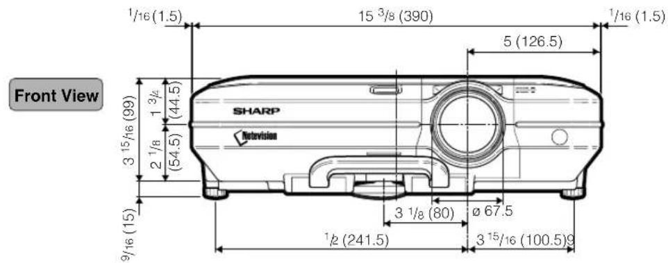

Glossary
Advanced intelligent compression
High quality resizing of lower and higher resolution images to fit the projector's native resolution.
Anti-theft
If the "Keycode" set in the projector is not correctly entered, the projector will not operate even if signals are entered.
Aspect Ratio
Width and height ratio of an image. The normal aspect ratio of a computer and video image is 4:3. There are also wide images with an aspect ratio of 16:9 and 21:9.
Auto Sync
Optimizes projected computer images by automatically adjusting certain characteristics.
Background
Initial setting image projected when no signal is being output.
Border
Projects a 4:3 image fully within a 16:9 screen by keeping the aspect ratio at 4:3.
Clock
Clock adjustment is used to adjust vertical noise when clock level is incorrect.
CLR Temp (Color temperature)
Function that can be used to adjust the color temperature to suit the type of image input to the projector. Decrease the color temperature to create warmer, reddish images for natural flesh tones, or increase to create cooler, bluish images for a brighter picture.
C.M.S. (Color Management System)
Function allows you individually adjust the display characteristics of six colors (R: Red, Y: Yellow, G: Green, C: Cyan, B: Blue, M: Magenta)
Digital Shift Setting
Shifts image up or down easily by ▲, ▼ buttons when RESIZE mode of input image is BORDER, STRETCH or SMART STRETCH of the video or the DTV signals.
Dot by dot
Mode that projects images in their native resolution.
Gamma
Image quality enhancement function that offers a richer image by brightening the darker portions of the image without altering the brightness of the brighter portions. You can select four different modes: STANDARD, PRESENTATION, CINEMA and CUSTOM.
Keylock Level
Mode that can lock the operation of projector buttons to prevent mischief.
Keystone correction
Function to digitally correct a distorted image when the projector is set up at an angle, smoothens out jaggies on keystone images and compresses the image not only horizontally but vertically keeping the 4:3 aspect ratio.
Notevision Lock Down
A new ceiling mounting mechanism that is effective in anti-theft and realizing improved installation strength.
Password
A password is set so that changes cannot be made in the settings of the "Options (2)" menu.
Phase
Phase shift is a timing shift between isomorphic signals with the same resolution. When phase level is incorrect, the projected image typically displays horizontal flicker.
Picture in Picture
Allows you to add video images onto a data screen image, providing you with even more effective presentations.
Progressive Mode
The progressive display projects a smoother video image. You can select three different modes: 2D Progressive, 3D Progressive and Film Mode.
Resize
Allows you to modify or customize the picture display mode to enhance the input image. You can select six different modes: NORMAL, FULL, DOT BY DOT, BORDER, STRETCH and SMART STRETCH.
Smart Stretch
Projects the image fully in a 16:9 screen by enlarging only the surrounding areas while keeping the aspect ratio in the middle part of the image at 4:3.
sRGB
An international standard of color reproduction regulated by the IEC (International Electrotechnical Commission). As the fixed color area has been decided by the IEC, the color changes according to LCD features, so that the images are displayed in a natural tint based on an original image, when switching to the "sRGB" mode.
Stretch
Mode that stretches the 4:3 image horizontally to display it fully on a 16:9 screen.
2D Progressive 47
3D Progressive 47
AC socket 17
Adjusting Computer Images 48
Adjusting the Lens 26
Adjusting the Picture 46
Adjustment buttons 42
Adjustment feet 25
Air filter 81
All Reset 77
Anti-Theft 75
Aspect ratio 52
AUDIO input 1, 2 terminal.... 17
AUDIO (L/R) input 3, 4 terminals.... 19
AUDIO OUTPUT terminal 21
Auto Power off....70
Auto Search 64
Auto Sync adjustment 50
AUTO SYNC button 50
Auto Sync Disp 50
BACK button 12
Background 68
Batteries 13
BLACK SCREEN button 58
BORDER 53
BREAK TIMER button 59
Carrying handle 10
Ceiling-mount setup 32
Chroma 61
Clock 48
CLR Temp (Color Temperature) 46
C.M.S. 60
Color Selected 60
Computer audio cable 17
Digital Shift Setting 39
DIN-D-sub RS-232C adaptor 22
DNR 65
DOT BY DOT 52
ENLARGE buttons 55
ENTER button 42
Exhaust vent 80
FAO 63
Film Mode 47
Fine Sync 48
Focus ring 26
FORWARD button 12
FREEZE button.... 54
FULL 52
GAMMA button 56
Keystone correction 38
Lamp 85
Lamp indicator 83
Lamp Life 70
Lens cap 10
Lightness 61
MENU button 42
MUTE button 36
NORMAL 52
ON button 34
Optional cables 14
OSD Display 65
OUTPUT (INPUT 1, 2) terminal 69
Password 73
PDF 9
Phase 48
Pict in Pict 57
PinP button 57
Power cord 17
Power indicator 34
Power Save 69
PRJ mode 71
Progressive Mode 47
Remote control 12
Remote control sensor 13
Remote receiver 24
Replacing the lamp 85
RESIZE button 52
Reversing/Inverting Projected Images 71
RGB cable 17
RS-232C terminal 22
Save Setting 48
Select Setting.... 49
Selecting the on-screen display language ...... 36
Signal Info 49
Signal Type 46
SMART STRETCH 53
Speaker 63
Special Modes 49
sRGB 60
STANDBY button 37
Startup image 68
Status 78
STRETCH 53
Supplied accessories.... 14
Target 60
Temperature warning indicator 83
UNDO button 39
USB cable 24
VAO 63
Video System 66
VOLUME buttons 35
WIRED R/C JACK.... 23
WIRED REMOTE control input terminal 23
Zoom knob 26
SHARP®
SHARP CORPORATION
- LCD PROJECTOR
- IMPORTANT
- DANGER
- INTRODUCTION
- ENGLISH
- WARRANTY
- CONSUMER PRODUCT SAFETY ACT
- WARNING
- INFORMATION
- PRODUCT DISPOSAL
- CAUTION CONCERNING THE LAMP REPLACEMENT
- LAMP REPLACEMENT CAUTION
- PRECAUTIONS A OBSERVER LORS DU REMPLACEMENT DE LA LAMPE
- WHEN ATTACHING THE "QUICK GUIDE" LABEL
- OUTSTANDING FEATURES
- ULTRA HIGH BRIGHTNESS FROM A COMPACT PROJECTOR
- SIMPLE & EASY OPERATION
- SUPERIOR PC COMPATIBILITY
- ADVANCED COMPUTER & VIDEO INTEGRATED COMPOSER TECHNOLOGY
- THEFT DETERRENT AND SECURITY
- CONNECTIONS AND SETUP
- BASIC OPERATION
- EASY TO USE FUNCTIONS
- SELECTING THE TRANSMISSION SPEED
- SETTING UP A PASSWORD
- SETTING THE ANTI-THEFT
- INITIALIZING THE SETTINGS
- DISPLAYING THE ADJUSTMENT SETTINGS
- APPENDIX
- REGARDING THE LAMP
- CONNECTING PIN ASSIGNMENTS
- (RS-232C) SPECIFICATIONS AND
- WIRED REMOTE CONTROL TERMINAL
- IMPORTANT SAFEGUARDS
- CAUTION: PLEASE READ ALL OF THESE INSTRUCTIONS BEFORE YOU OPERATE THIS PRODUCT AND SAVE THESE INSTRUCTIONS FOR LATER USE
- READ INSTRUCTIONS
- RETAIN INSTRUCTIONS
- HEED WARNINGS
- FOLLOW INSTRUCTIONS
- CLEANING
- ATTACHMENTS
- WATER AND MOISTURE
- ACCESSORIES
- TRANSPORTATION
- VENTILATION
- POWER SOURCES
- GROUNDING OR POLARIZATION
- POWER-CORD PROTECTION
- LIGHTNING
- OVERLOADING
- OBJECT AND LIQUID ENTRY
- SERVICING
- DAMAGE REQUIRING SERVICE
- REPLACEMENT PARTS
- SAFETY CHECK
- WALL OR CEILING MOUNTING
- HEAT
- INTELLECTUAL PROPERTY RIGHTS
- READ BEFORE USING THE PRODUCT
- BE SURE TO READ THE FOLLOWING SAFEGUARDS WHEN SETTING UP YOUR PROJECTOR
- CAUTION CONCERNING THE LAMP UNIT
- CAUTIONS CONCERNING THE SETUP OF THE PROJECTOR
- DO NOT SET UP THE PROJECTOR IN PLACES EXPOSED TO DIRECT SUNLIGHT OR BRIGHT LIGHT
- THE PROJECTOR MAY SAFELY BE TILTED TO A MAXIMUM ANGLE OF 12 DEGREES
- DO NOT SUBJECT THE PROJECTOR TO HARD IMPACT AND/OR VIBRATION
- REST YOUR EYES OCCASIONALLY
- AVOID LOCATIONS WITH HIGH OR LOW TEMPERATURE
- DO NOT BLOCK THE EXHAUST AND INTAKE VENTS
- CAUTIONS REGARDING THE TRANSPORTATION OF THE PROJECTOR
- OTHER CONNECTED EQUIPMENT
- USING THE PROJECTOR IN OTHER COUNTRIES
- TEMPERATURE MONITOR FUNCTION
- INFO
- HOW TO ACCESS THE PDF OPERATION MANUALS (WINDOWS, MACINTOSH)
- TO INSTALL ACROBAT READER FROM THE CD-ROM
- FOR WINDOWS
- FOR MACINTOSH
- FOR OTHER OPERATING SYSTEMS
- FOR OTHER LANGUAGES
- ACCESSING THE PDF MANUALS
- NOTE
- PART NAMES
- PROJECTOR (FRONT AND TOP VIEW)
- PROJECTOR (REAR VIEW)
- USING THE KENSINGTON LOCK
- CARRYING THE PROJECTOR
- USING THE REMOTE CONTROL
- AVAILABLE RANGE OF THE REMOTE CONTROL
- WHEN USING THE REMOTE CONTROL
- INSERTING THE BATTERIES
- INCORRECT USE OF THE BATTERIES MAY CAUSE THEM TO LEAK OR EXPLODE. PLEASE FOLLOW THE PRECAUTIONS BELOW
- CAUTION
- SUPPLIED ACCESSORIES
- OPTIONAL CABLES
- CONNECTING THE PROJECTOR TO OTHER DEVICES
- BEFORE CONNECTING
- THIS PROJECTOR CAN BE CONNECTED TO
- A COMPUTER USING
- COMPONENT VIDEO OR AUDIO-VISUAL EQUIPMENT
- AN AMPLIFIER OR AUDIO COMPONENTS USING
- A MONITOR USING
- CONNECTING THE POWER CORD
- CONNECTING THE PROJECTOR TO A COMPUTER
- CONNECTING TO A COMPUTER USING THE RGB CABLE
- CONNECTING THE THUMBSCREW CABLES
- PLUG AND PLAY" FUNCTION (WHEN CONNECTING TO A 15-PIN TERMINAL)
- CONNECTING TO VIDEO EQUIPMENT
- CONNECTING TO VIDEO EQUIPMENT USING AN S-VIDEO, A COMPOSITE VIDEO OR AN AUDIO CABLE
- CONNECTING TO COMPONENT VIDEO EQUIPMENT
- CONNECTING TO AN AMPLIFIER
- CONNECTING TO AN AMPLIFIER OR OTHER AUDIO COMPONENTS
- CONTROLLING THE PROJECTOR BY A COMPUTER
- CONNECTING TO A COMPUTER USING A DIN-D-SUB RS-232C ADAPTOR AND AN RS-232C SERIAL CONTROL CABLE
- CONNECTING TO A MONITOR
- WATCHING IMAGES ON BOTH THE PROJECTOR AND A MONITOR
- USING AS A WIRED REMOTE CONTROL
- CONNECTING THE REMOTE CONTROL TO THE PROJECTOR
- USING THE WIRELESS PRESENTATION FUNCTION OF THE REMOTE CONTROL
- USING THE WIRELESS PRESENTATION FUNCTION
- SETUP
- USING THE ADJUSTMENT FEET
- ADJUSTING THE LENS
- SETTING UP THE SCREEN
- THROW DISTANCE
- STANDARD SETUP (FRONT PROJECTION)
- EXAMPLE OF STANDARD SETUP
- SCREEN SIZE AND PROJECTION DISTANCE
- STANDARD LENS
- THROW RATIO
- TO
- [FEET, INCHES]
- [M, CM]
- AN-C41MZ (OPTIONAL ACCESSORY)
- AN-C27MZ (OPTIONAL ACCESSORY)
- AN-C12MZ (OPTIONAL ACCESSORY)
- PROJECTING A REVERSED/INVERTED IMAGE
- PROJECTION FROM BEHIND THE SCREEN
- PROJECTION USING A MIRROR
- CEILING-MOUNT SETUP
- BASIC PROCEDURE
- PLUG THE POWER CORD INTO THE WALL OUTLET
- PRESS ON ON THE PROJECTOR OR ON THE REMOTE CONTROL
- VOLUME
- SELECTING THE ON-SCREEN DISPLAY LANGUAGE
- TURNING THE POWER OFF
- CORRECTING TRAPEZOIDAL DISTORTION (KEYSTONE CORRECTION)
- CORRECTING TRAPEZOIDAL DISTORTION
- PRESS
- PRESS ▲, ▼, ◀ AND ▶ TO ADJUST THE KEYSTONE CORRECTION
- DIGITAL SHIFT SETTING
- INPUT 3 / 4 MODE
- USING THE MENU SCREEN
- MENU SELECTIONS (ADJUSTMENTS)
- PRESS ◀ OR ▶ TO SELECT THE MENU YOU WANT TO ADJUST
- PRESS ▲▲R▼TO SELECT THE ITEM YOU WANT TO ADJUST
- PRESS ◀ OR ▶ TO ADJUST THE ITEM SELECTED
- MENU SELECTIONS (SETTINGS)
- ADJUSTING THE PICTURE
- ADJUSTING IMAGE PREFERENCES
- SELECTING THE SIGNAL TYPE
- PROGRESSIVE MODE
- D PROGRESSIVE
- D 3D PROGRESSIVE
- FILM MODE
- ADJUSTING COMPUTER IMAGES
- COMPUTER IMAGE ADJUSTMENT
- SAVING ADJUSTMENT SETTINGS
- SELECTING ADJUSTMENT SETTINGS
- SPECIAL MODE SETTINGS
- CHECKING THE INPUT SIGNAL
- AUTO SYNC ADJUSTMENT
- AUTO SYNC DISPLAY FUNCTION
- SELECTING THE PICTURE DISPLAY MODE
- SWITCHING THE PICTURE DISPLAY USING DIFFERENT INPUT SIGNALS
- DISPLAYING A STILL IMAGE
- FREEZING A MOVING IMAGE
- ENLARGING A SPECIFIC PORTION OF AN IMAGE
- DISPLAYING AN ENLARGED PORTION OF AN IMAGE
- GAMMA CORRECTION FUNCTION
- ADJUSTING GAMMA CORRECTION
- TO RETURN TO THE DEFAULT SETTINGS, PRESS ⏻ WHEN “GAMMA” IS DISPLAYED
- DISPLAYING DUAL PICTURES (PICT IN PICT)
- DISPLAYING THE INSET PICTURE
- BLACKING OUT THE PROJECTED IMAGE
- TO RETURN TO THE ORIGINAL PROJECTED IMAGE, PRESS AGAIN
- DISPLAYING THE BREAK TIMER
- DISPLAYING AND SETTING THE BREAK TIMER
- COLOR MANAGEMENT SYSTEM (C. M. S.)
- SELECTING THE COLOR REPRODUCTION MODE
- SELECTING THE TARGET COLOR
- SETTING THE BRIGHTNESS OF THE TARGET COLOR
- SETTING THE CHROMATIC VALUE OF THE TARGET COLOR
- SETTING THE HUE OF THE TARGET COLOR
- RESETTING USER-DEFINED COLOR SETTINGS
- OVERVIEW OF ALL COLOR SETTINGS
- SETTING THE AUDIO OUTPUT TYPE
- SETTING ON/OFF THE INTERNAL SPEAKER
- AUTO SEARCH FUNCTION
- USING AUTO SEARCH
- VIDEO DIGITAL NOISE REDUCTION (DNR) SYSTEM
- REDUCING IMAGE NOISE
- SETTING ON-SCREEN DISPLAY
- TURNING OFF THE ON-SCREEN DISPLAY
- SETTING THE VIDEO SYSTEM
- SAVING PROJECTED IMAGES
- CAPTURING THE IMAGE
- DELETING THE CAPTURED IMAGE
- SETTING A BACKGROUND IMAGE
- SELECTING A BACKGROUND IMAGE
- SELECTING A STARTUP IMAGE
- SELECTING THE ECONOMY MODE
- SETTING THE POWER SAVE MODE
- MONITOR OUT/RS-232C OFF FUNCTION
- AUTO POWER OFF FUNCTION
- DISPLAYING THE REMAINING LAMP LIFE (PERCENTAGE)
- CHECKING THE REMAINING LAMP LIFE (PERCENTAGE)
- REVERSING/INVERTING PROJECTED IMAGES
- SETTING THE PROJECTION MODE
- LOCKING THE OPERATION BUTTONS ON THE PROJECTOR
- SETTING UP THE KEYLOCK
- CANCELING THE KEYLOCK SETTING
- SELECTING THE TRANSMISSION SPEED (RS-232C)
- ENTERING THE PASSWORD
- CHANGING THE PASSWORD
- IF YOU FORGET YOUR PASSWORD
- ENTERING THE KEYCODE
- PRESS ANY BUTTON YOU LIKE ON THE REMOTE CONTROL OR PROJECTOR TO SET THE FIRST DIGIT IN "NEW CODE
- CHANGING THE KEYCODE
- RETURNING TO THE DEFAULT SETTINGS
- OVERVIEW OF ALL MENU SETTINGS
- MAINTENANCE
- CLEANING THE PROJECTOR
- CLEANING THE LENS
- CLEANING THE EXHAUST AND INTAKE VENTS
- REPLACING THE AIR FILTER
- CLEANING AND REPLACING THE BOTTOM AIR FILTER
- CLEAN THE AIR FILTER
- REPLACE THE AIR FILTER
- REPLACE THE FILTER COVER
- MAINTENANCE INDICATORS
- ABOUT THE TEMPERATURE WARNING INDICATOR
- ABOUT THE LAMP INDICATOR
- LAMP
- IMPORTANT NOTE TO U.S. CUSTOMERS
- CAUTION CONCERNING THE LAMP
- REPLACING THE LAMP
- REMOVING AND INSTALL- ING THE LAMP UNIT
- REMOVE THE LAMP UNIT
- INSERT THE NEW LAMP UNIT
- ATTACH THE LAMP UNIT COVER
- RESETTING THE LAMP TIMER
- CONNECT THE POWER CORD
- RESET THE LAMP TIMER
- PIN NO. SIGNAL NAME I/O REFERENCE
- (RS-232C) SPECIFICATIONS AND COMMAND SETTINGS
- PC CONTROL
- COMMUNICATION CONDITIONS
- BASIC FORMAT
- COMMANDS
- EXAMPLE
- WIRED REMOTE CONTROL TERMINAL SPECIFICATIONS
- SPECIFICATIONS OF WIRED REMOTE CONTROL INPUT
- SHARP REMOTE CONTROL SIGNAL FORMAT
- TRANSMISSION CONTROL CODE
- COMPUTER COMPATIBILITY CHART
- COMPUTER
- U.S.A. SHARP ELECTRONICS CORPORATION
- CANADA SHARP ELECTRONICS OF CANADA LTD
- MEXICO SHARP ELECTRONICS CORPORATION MEXICO
- LATIN AMERICA SHARP ELECTRONICS CORP. LATIN AMERICAN
- GERMANY SHARP ELECTRONICS (EUROPE) GMBH
- U.K. SHARP ELECTRONICS (U.K.) LTD
- ITALY SHARP ELECTRONICS (ITALY) S.P.A
- FRANCE SHARP ELECTRONICS FRANCE
- SPAIN SHARP ELECTRONICA ESPANA, S.A
- SWITZERLAND SHARP ELECTRONICS (SCHWEIZ) AG
- SWEDEN SHARP ELECTRONICS ( NORDIC ) AB
- AUSTRIA SHARP ELECTRONICS AUSTRIA (GES.M.B.H.)
- BENELUX SHARP ELECTRONICS BENELUX BV
- AUSTRALIA SHARP CORPORATION OF AUSTRALIA
- NEW ZEALAND SHARP CORPORATION OF NEW ZEALAND
- SINGAPORE SHARP-ROXY SALES (S) PTE. LTD
- HONG KONG SHARP-ROXY (HK) LTD
- TAIWAN SHARP CORPORATION (TAIWAN)
- MALAYSIA SHARP-ROXY SALES & SERVICE CO
- U.A.E. SHARP MIDDLE EAST FZE
- THAILAND SHARP THEBNAKORN CO. LTD
- KOREA SHARP ELECTRONICS INCORPORATED OF
- INDIA SHARP BUSINESS SYSTEMS (INDIA)
- SPECIFICATIONS
- DIMENSIONS
- GLOSSARY
- ADVANCED INTELLIGENT COMPRESSION
- ANTI-THEFT
- ASPECT RATIO
- AUTO SYNC
- BACKGROUND
- BORDER
- CLOCK
- CLR TEMP (COLOR TEMPERATURE)
- C.M.S. (COLOR MANAGEMENT SYSTEM)
- DOT BY DOT
- GAMMA
- KEYLOCK LEVEL
- KEYSTONE CORRECTION
- NOTEVISION LOCK DOWN
- PASSWORD
- PHASE
- PICTURE IN PICTURE
- RESIZE
- SMART STRETCH
- SRGB
- STRETCH
- SHARP®
- SHARP CORPORATION
Brand : SHARP
Model : XG-C55X
Category : Projector