AX11 - Uncategorized Verkada - Free user manual and instructions
Find the device manual for free AX11 Verkada in PDF.


| Product Type | Cloud-Managed Access Control Unit |
| Model | AX11 |
| Brand | Verkada |
| Door Support | Up to 1 door |
| Reader Ports | 2 ports for Wiegand/OSDP readers |
| Power Input | Power over Ethernet (PoE 802.3af) or 12V DC |
| Dimensions | 30.5 x 21.6 x 5.1 cm (12.0 x 8.5 x 2.0 in) |
| Weight | 1.5 kg (3.3 lb) |
| Operating Temperature | 0°C to 40°C (32°F to 104°F) |
| Remote Management | Verkada Command cloud platform |
| Security Protocol | AES-256 encryption, TLS 1.2, secure boot |
| Installation | DIN rail or wall mountable |
| Maintenance | Automatic cloud firmware updates |
| Compatibility | Any Wiegand or OSDP card reader |
| Lock Output | 12V DC lock output with built-in fail-safe/fail-secure |
| Inputs/Outputs | Door contact input, request-to-exit input |
| Certifications | UL 294, FCC, CE |
| Spare Parts | Customer-replaceable; contact Verkada Support |
Frequently Asked Questions - AX11 Verkada
User questions about AX11 Verkada
0 question about this device. Answer the ones you know or ask your own.
Ask a new question about this device
Download the instructions for your Uncategorized in PDF format for free! Find your manual AX11 - Verkada and take your electronic device back in hand. On this page are published all the documents necessary for the use of your device. AX11 by Verkada.
USER MANUAL AX11 Verkada
Introduction
Document Details
Note
This equipment has been tested and found to comply with the limits for a Class A digital device, pursuant to part 15 of the FCC rules. These limits are designed to provide reasonable protection against harmful interference when the equipment is operated in a commercial environment.
This equipment generates, uses and can radiate radio frequency energy and, if not installed and used in accordance with the instruction manual, may cause harmful interference to radio communications. Operation of this equipment in a residential area is likely to cause harmful interference in which case the user will be required to correct the interference at his own expense.
This equipment is for use in a restricted access area.
Warning
Ensure power is disconnected from the AX11 before servicing the product or connecting/disconnecting peripherals.
Document revision
V1.2
Levels of Access Control
- Attack Level/Grade: Level I
• Endurance Level/Grade: Level I
• Line Security Level/Grade: Level I
• Standby Power Level/Grade: Level I
Firmware
Firmware version can be verified and upgraded in the Command dashboard at command.verkada.com.
Introduction
AX11 Overview
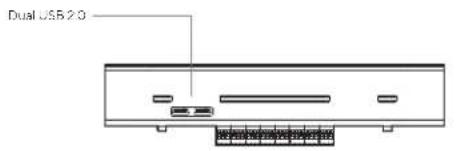


AX11 Recommended Testing
To ensure ongoing functionality of AX11, it is recommended to check the following interfaces every 6 months:
- Short each input to its adjacent COM port and verify LED illuminates
- Use multimeter to confirm expected impedance across relay outputs
- Short across NC and COM
- Open across NO and COM
- Use multimeter to verify aux voltage is supplied at 12V outputs

AX11 Status LED Behavior

Solid Orange
Controller is on and booting up

Flashing Orange
Controller is updating firmware

Flashing Blue
Controller is managing inputs and outputs but cannot reach the server

Solid Blue
Controller is managing inputs and outputs and is connected to the server
AX11 AC Power LED Behavior

Solid Green
AC power supplied to controller
AX11 Technical Specifications
| Power Consumption | 60W Max | |
| AC Power Input | 110-240VAC50-60Hz | |
| Inputs | 16 Dry InputsNominal 5VDC | |
| Relay Outputs | 16 Dry Relays1A/24VDC Contacts | |
| AUX Power | 2 External Outputs1A/12V Power Each2A Combined Max | |
| Dimensions | With Mount415.6mm (L) x 319.6mm (W) x 111.74 (H) | Without Mount415.6mm (L) x 319.6mm (W) x 105.74 (H) |
| Weight 8.3kg | ||
| Operating Temperature | 0°C - 50°C 5-90% Humidity | |
| Compliance | FCC, CE, UL 294, UL 62368-1/CSAC22.2, CAN/ULC-60839-11-1:2016, NDAA | |
| Connectivity | Ethernet: 100/1000Mbps RJ-45 cable connector for network connectionUSB 2.0 | |
| Included Accessories | Quick start guide, Install kit | |
| Mounting Options | Drywall anchors (M8) and screws (M5) |
Installation
Mounting
To remove the mounting plate, unscrew the two security torx screws from the inside.

Once the security screws are fully removed, slide the mounting plate down and away from the main enclosure.

Installation
Mounting
Drill four 5/16" ∅ holes into the wall. Insert the drywall anchors into the holes. Fasten the mounting plate onto the wall by installing the mounting screws into the wall anchors.
Drill four 5/32" ∅ holes into the wall. Fasten the mounting plate onto the wall by installing the mounting screws into the pilot holes.

Place the sheet metal enclosure over and onto the mounting plate tabs.

Fasten the two security torx screws to secure the enclosure to the mounting plate.

Wiring
Recommended Wiring
The AX11 card reader interface is capable of supporting Verkada Readers over RS-485 and standard Wiegand readers. The following table shows the wire types that are recommended for use with AX11.
| Signal AWG Twisted Pair Conductor Shielded Max Length | ||||
| Reader Option 1(Wiegand or AD31) | 22 Yes Yes 250ft | |||
| Reader Option 2(Wiegand or AD31) | 20 Yes Yes 300ft | |||
| Reader Option 3(Wiegand or AD31) | 18 Yes Yes 500ft | |||
| 12V Power (22 Gauge) 22 Yes Yes 600ft | ||||
| 12V Power (18 Gauge) | 18 | Yes | Yes | 1500ft |
| Inputs | 22 Yes Yes 1000ft | |||
| Dry Relay Output | 18 | Yes | Yes | 1500ft |
We recommend using one twisted pair for GND and Vin (power) and one twisted pair for the data (D0/D1 or A/B).
Wiring methods shall be in accordance with National Electrical Code, ANSI/NFPA 70.

Shield Wiring and Grounding
With the AX11, you must use shield wiring.
Drain wire of the cable should be secure to the nearest grounding point, indicated with ⏻ on the controller, with a conductive M4 screw.
Required Network Settings
An Ethernet connection with DHCP must be used to connect the AX11 to the Local Area Network (LAN). You also need to configure firewall settings to communicate with the AX11.
- TCP port 443
• UDP port 123 (NTP time synchronization)
Installation
Connecting Peripherals
Current Limiting Resistor
If a powered peripheral has inrush current over 10A, an in-line current limiting power resistor of 10Ω should be used to ensure peripheral does not exceed max power draw, which may disrupt normal operation.
Max Line Resistance
The maximum line resistance for input wire runs should be less than 100Ω , exclusive of end-of-line supervision resistors.
12V Power
12V Output terminals support up to 2A combined max.

Battery Backup
Battery should be sized to provide at least 4 hours of operation. The AX11 consumes 8.6W with no load (i.e., no inputs, outputs, or readers connected).
AC Field Wiring
If AC power is brought in via conduit, cut and splice wire going from AC inlet to PSU.
Inputs
AX11 has 16 Dry Contact Inputs. Nominal 5VDC. Line resistance should be less than 100Ω exclusive of EOL resistor.
![graph LR IN1 --> COM1["NO or NC"] GND --> COM1 GND --> NO2["NO or NC"] IN2 --> COM2["NO or NC"] IN2 --> NO2 COM1 --> Input1["Input 1"] COM2 --> Input2["Input 2"]](/content/2026/08/1621515/images/2d187f2888397c55c3d9de4b7457adb0a31b0c2e6ff2505adfd09a40784655aa.jpg)
Inputs 3 - 16 omitted from diagram, as wiring is identical for all inputs.
Relay Outputs
AX11 comes equipped with 16 Form C relays that can be driven dry. Max DC load: 24V @ 1A, Max DC current = 1A, Max DC voltage = 60VDC.
Installation
Connecting an Output
Warning
Ensure power is disconnected from the AX11 before plugging in or unplugging any of the terminal blocks. Failure to do so may damage the AX11
Wiring a Powered Lock
It is recommended to interface with an Access Power Controller (APC) to provide power to the accessory. If the APC detects the AX11 relay is triggered, it will trigger its own relay.
Fail Secure
Access Power ControllerAX11 Relay Output Lock

Fail Safe
Access Power ControllerAX11 Relay Output Lock

Depending on your APC and lock, your configuration may vary from the above.
Installation
Connecting a Reader
Wiring a Verkada or Wiegand Reader
The AX11 is rated to power readers at 12V up to 250mA via the + Vin and - GND connection. The drain wire of the shielded cable should be secured to nearest AX11 chassis ground.
Verkada Reader

Wiegand Reader

Verkada Reader
| Wire Color Signal | |
| Red 12V Power + | |
| Black 12V Power - | |
| Purple A | |
| Blue B |
Wiegand Reader
| Wire Color Signal | |
| Red 12V Power + | |
| Black 12V Power - | |
| Green Data 0 | |
| White/Gray Data 1 | |
| Brown Red LED | |
| Orange Green LED |
Installation
Battery Backup
Battery Backup
A 12V Battery can be connected to the F2 connectors located at the bottom of the AX11. You can fit one or two batteries at the bottom of the AX11.
We recommend and sell a 12 Volt 4.5 Ah Sealed Lead Acid Rechargeable battery.
If you are using two batteries, ensure they are wired in parallel.

![graph TD A["AX11 Battery Leads"] -->|+| B["Battery 1 12V 4.5 Ah"] A -->|-| C["Battery 1 12V 4.5 Ah"] B -->|+| D["+"] C -->|-| E["-"]](/content/2026/08/1621515/images/5c84ee45dd5a988d3422cf2d4cfb458d7da4a2e508be79e7e94deb2cfe526d4e.jpg)
Connect
Connect the AX11 to your network using either of the Ethernet ports located at the bottom of the controller. If you are installing multiple controllers, you can connect up to 4 additional controllers via the spare Ethernet port on each controller.
Connect the AX11 power supply to your standard power outlet (110VAC - 240VAC).
Appendix
Support
Thank you for purchasing this Verkada product. If for any reason things don't work right, or you need assistance, please contact us immediately.
verkada.com/support Sincerely, The Verkada Team
- DOCUMENT DETAILS
- NOTE
- WARNING
- DOCUMENT REVISION
- LEVELS OF ACCESS CONTROL
- FIRMWARE
- AX11 OVERVIEW
- AX11 RECOMMENDED TESTING
- AX11 STATUS LED BEHAVIOR
- AX11 AC POWER LED BEHAVIOR
- MOUNTING
- INSTALLATION
- WIRING
- RECOMMENDED WIRING
- SHIELD WIRING AND GROUNDING
- REQUIRED NETWORK SETTINGS
- CONNECTING PERIPHERALS
- CURRENT LIMITING RESISTOR
- MAX LINE RESISTANCE
- V POWER
- BATTERY BACKUP
- AC FIELD WIRING
- INPUTS
- RELAY OUTPUTS
- CONNECTING AN OUTPUT
- WIRING A POWERED LOCK
- FAIL SECURE
- FAIL SAFE
- CONNECTING A READER
- WIRING A VERKADA OR WIEGAND READER
- CONNECT
- SUPPORT
Brand : Verkada
Model : AX11
Category : Uncategorized