
L9071 - Uncategorized Schlage - Free user manual and instructions
Find the device manual for free L9071 Schlage in PDF.


| Product Type | Commercial Grade 2 Heavy-Duty Cylindrical Lever Lock |
| Model Number | L9071 |
| Series | Schlage L Series |
| Function | Keyed Entry (key outside, lever inside) |
| Grade | ANSI/BHMA Grade 2 |
| Door Thickness | Fits standard 1-3/8" to 1-3/4" doors |
| Backset | Adjustable 2-3/8" or 2-3/4" |
| Lever Style | Heavy-duty die-cast zinc curved lever |
| Cylinder Type | 6-pin Schlage C keyway |
| Strike Included | Adjustable latch strike plate |
| Latch Bolt | Stainless steel, 1/2" throw |
| Material | Die-cast zinc chassis and lever |
| Finish Options | Satin chrome, bright brass, oil-rubbed bronze |
| Dimensions | 5.2" H x 3.1" W x 2.6" D (approx.) |
| Weight | 5.6 lb (2.54 kg) |
| Security Features | Anti-pick security pins, free-spinning collar, hardened steel insert |
| Certifications | UL/cUL listed, ADA compliant |
| Warranty | Limited lifetime mechanical warranty |
| Installation | Fits standard 2-1/8" door prep, template included |
| Maintenance | Wipe with damp cloth, lubricate with graphite powder |
| Repairability | Replacement parts available: cylinders, levers, springs |
| Package Includes | Lockset, strike plate, mounting screws, template, user guide |
Frequently Asked Questions - L9071 Schlage
User questions about L9071 Schlage
0 question about this device. Answer the ones you know or ask your own.
Ask a new question about this device
Download the instructions for your Uncategorized in PDF format for free! Find your manual L9071 - Schlage and take your electronic device back in hand. On this page are published all the documents necessary for the use of your device. L9071 by Schlage.
USER MANUAL L9071 Schlage
L-Series Service Manual

Contents
Introduction....1
Standard Features * 1
Lock Assembly Drawing Index 3
Trim Assemblies 15-34
Single Dummy Trim: L0170 15
Double Dummy Trim: L0172....16
L400-Series Deadbolt Trim: L460, L462, L463, L464, L480, L496 17
Passage Latch Trim: L9010....18
Emergency Button x Turn Trim: L9040, LV9040, L9440, LV9440....19
Privacy x Turns Both Sides Trim: L9040 x XL11-446, LV9040 x XL11-446....20
Coin Turn Outside x Turn Trim: L9044, LV9044, L9444, LV9444....21
Cylinder x Turn Trim: L9050, LV9050, L9056, LV9056, L9453, LV9453, L9456, LV9456, L9473 22
Double Cylinder Trim: L9060, LV9060, L9071, LV9071, L9077, LV9077, L9082, LV9082, L9457, LV9457, L9462 x XL11-886, L9466 23
Cylinder Outside Trim: L9070, LV9070, L9076, LV9076, L9080, LV9080, L9080EL/EU, LV9080EL/EU, L9080EL/EU-RX, L9464 x XL11-886, L9465....24
Electrically Locked/Unlocked Both Sides Trim: L9082EL/EU 25
Active Double Dummy Trim: L9110 x XL11-741....26
Single Dummy with Case Trim: L9175, L9177 (Discontinued)....27
Double Dummy with Case Trim: L9176, L9178 (Discontinued)....28
L9000-Series Deadbolt Trim: L9460, L9462, L9463, L9464 ....29
Deadbolt with Fixed Double Dummy Trim: L9460 x XL11-635....30
Fixed Outside x Turn Trim: L9460 x XL11-886, L9480, LV9480, L9485, LV9485 31
Institution Deadbolt Trim: L9482 x XL11-543, LV9482 x XL11-543....32
Prison Lock Trim: L9485 x XL11-557 33
Hotel with Indicator Trim: L9486, LV9486, L9486 x L583-375, LV9486 x L583-375, L9496, LV9496....34
Trim Assemblies Chart.... 36-47
Lock Case Assemblies 48-85
L460, L462, L463, L464, L480, L496....48
L9010....49
L9040, L9040 x XL11-446, L9044 ....50
LV9040, LV9040 x XL11-446, LV9044 ....51
L9050, L9060, L9070, L9071....52
LV9050, LV9060, LV9070, LV9071....53
L9056....54
LV9056....55
L9076, L9077....56
LV9076, LV9077 57
L9080....58
LV9080....59
L9080EL, L9080EL-RX....60
LV9080EL 61
L9080EU, L9080EU-RX....62
LV9080EU....63
L9082....64
LV9082....65
L9082EL 66
L9082EU 67
L9110 x XL11-741 68
L9175....69
L9176....70
L9440, L9444....71
LV9440, LV9444....72
L9453....73
LV9453....74
L9456, L9457, L9496....75
LV9456, LV9457, LV9496 76
L9460, L9462, L9463, L9464....77
L9460 x XL11-635 78
L9460 x XL11-886, L9462 x XL11-886, L9464 x XL11-886....79
L9465, L9466, L9473....80
L9480, L9485, L9486, L9486 x L583-375....81
LV9480, LV9485, LV9486, LV9486 x L583-375....82
L9482 x XL11-543 83
LV9482 x XL11-543 84
L9485 x XL11-557 85
Lock Case Assembly Compatibility 86
Assembly of Lock Case Parts....87-88
Trim Options....89
Cast or Forged Lever Designs....89
Rose Trim A or B 91
L Escutcheon Trim 92
N Escutcheon Trim....94
Decorative Trim 95
danmark Stainless Steel Levers 96
Trim Options....97
Coin Turn....97
Coin Turn and Plug 97
"Do Not Disturb" Indicator....97
"Occupied" Indicator 97
Thumbturn 97
ADA Cylinder Turn 97
Cylinder Turn....97
"EZ" Thumbturn (ADA) for Rose Trim....97
"EZ" Thumbturn (ADA) x Knob/Lever with L or N Escutcheon....97
"EZ" Thumbturn (ADA) x Blank with L Escutcheon....97
Emergency Turn....98
Emergency Button 98
Modifi ed Inside and Outside 03 Lever for Folger Adam Co® Lever Trak™ 98
Tactile Warning (Knurling)....98
Trim Assembly Parts....99
Escutcheon Thru-Bolt/Screws....99
Standard Screw Packs....99
Tamper Resistant Torx Screw Packs....99
Drivers to Operate Occupancy Indicator....99
Mounting Posts 100
Spindles and Springs....100
Mounting Plate for Trim One Side Only....100
Armor Fronts....101
Strikes 102
Cylinder Specifications ....103
Full Face Cylinders....104
Concealed Cylinders 106
Full Size Interchangeable Cores....108
Small Format Interchangeable Core 111
Blocking and Compression Rings 113
Dimensions for Blocking Rings 113
Full Size Core Blocking Ring Requirements, L-Series and LV-Series 113
SFIC Blocking Ring Requirements, L-Series and LV-Series....113
Special Options....114
Solid Latchbolt 114
Armor Front with Deadbolt Hole 114
L9000 Lead Lining XL11-515....114
L400 Lead Lining XL12-216....114
Anti-Ligature Knob Trim 114
Anti-Ligature Thumbturn 114
Anti-Ligature Conversion Kits 114
Special Cylinder Applications ....114
Installation Tools and Kits....115
40-054 Maintenance Kit Contents ....115
Electrically Locking 116
L9080 EL Electrically Locked (Fail Safe): 116
L9080 EU Electrically Unlocked (Fail Secure): 116
Request to Exit (RX) Feature*: 116
L9082 EL or EU Electrically Locked or Unlocked Both Sides:....116
Replacement Kit: 116
Electrical Requirements: 116
Typical Installation:....116
Lubrication Specifications....117
Door Handing....118
Changing the Lock Hand 118
Changing Cylinder Turn Hand....118
L9000-Series Installation Sheet—Page 1 119-134
L400-Series Installation Sheet–Page 1 135-136
Ordering Procedures 137
Finishes 138
Finish Codes and Descriptions....138
Limited Warranty 139
Introduction
This manual contains a complete listing of parts and assemblies for L-Series mortise locks manufactured by Schlage Lock Company. This edition lists components of L-Series locks manufactured after June, 2001. All lock case covers are labeled with dates to identify year of manufacture. Example: 12507 = the 125th day of 2007.
Exploded views of each lock function and trim assembly are provided with accompanying charts to identify parts for replacement purposes. Exploded views of trim are shown with parts for standard size doors. In addition, this manual provides lock trim ordering procedures, cylinder length charts by door range, and all auxiliary components of the L-9000/LV-9000 and L400-Series mortise locks.
Standard Features*
| Certifi cations L/LV9000: ANSI A156.13, 1994, Series 1000, Grade 1 Operational, Grade 1 Security, UL Listed for 3 hour fi re door (except L9076 and L9077). With Interchangeable Core Cylinders: Grade 2 Security L400: ANSI A156.5, 2001, Grade 1, UL Listed for 3 hour fi re door. | |
| Case Size | 47/16 " x 61/16 " x 1"; L400: 47/16 " x 35/8 " x 1" |
| Armor Front | L/LV9000: 11/4 " x 8"; L400: 11/4 " x 519/32 " |
| Deadbolt 1" Throw stainless steel | |
| Latchbolt | 1/2 " Throw stainless steel with anti-friction tongue |
| Strike | L/LV9000: 11/4 " x 47/8 ", Square corner, 13/16 " lip, box; L400: 11/8 " x 35/8 ", Square corner, box |
| Backset | 23/4 " |
| Cylinder 6-Pin solid brass, keyed 6-pin, C123 keyway, keyed different (KD)* | |
| Door Range | 13/4 " and up |
| Keys Two nickel silver cut keys per lock, 6-pin, C123 section* | |
* Items specified in C keyway will be furnished with cylinders keyed 5-pin and with 5-pin keys unless otherwise specified.
NOTE: Locks are furnished with standard features unless otherwise specified.

Introduction
Dot Charts
• = (1) Part
2 = (2) Parts
Example:
| P/N Description | L9110/XL11-741 | L9175 | L9176 | L9177 (disc) | L9178 (disc) | L9410 (disc) | L9440 | LV9440 | L9444* | LV9444* | L9453 | LV9453 | L9456 | LV9456 | L9457 | LV9457 | L9460 | L9460/XL11-635 | L9460/XL11-886 | L9462 | L9462/XL11-886 | L9463 | L9464 | L9464/XL11-886 | L9465 | L9466 | L9473 | L9480 | LV9480 | L9482/XL11-543 | LV9482/XL11-543 | L9485 | LV9485 | L9485/XL11-557** | LV9485/XL11-557 | L9486***z | LV9486***z | L9496 | LV9496 | |
| 30-001 Cl | Classic Mortise Cylinder | • | • | • | • | • | 2 | 2 | • | • | • | 2 | 2 | • | • | • | • | 2 | • | • | • | 2 | 2 | • | • | • | • | |||||||||||||
All parts shown in dot charts are standard. Additional options may be available. See current Schlage Price Book for available options, pricing and ordering procedures.
Lock Assembly Drawing Index
The Lock Assembly Drawing Index provides representations and descriptions of available functions. Page numbers for full trim and chassis drawings are referenced.
![graph TD A["Emergency Turn"] --> B["Auxiliary Latch"] C["Coin Turn"] --> B D["Cylinder"] --> B B --> E["Electrified"] E --> F["Deadbolt"] F --> G["Latchbolt"] G --> H["RX"] H --> I["Two-piece Spindle"] H --> J["Solid Spindle"] H --> K["One-piece Outside Spindle"] L["Inside"] --> M["Thumbturn"] N["Cy…](/content/2026/08/1618939/images/41f231db59a3786c02465106e42b441a23787347dbac017a62187c459776e554.jpg)
Lock Assembly Drawing Index
| FUNCTIONSANSI/BHMA A156.13, 1994, Series 1000, Grade 1 | Trim Assembly Page Number | Lock Assembly Page Number | Lock Case Page Number | |
| Non-Keyed LocksSCHLAGE ANSIL0170 | ||||
 | Single Dummy TrimKnob/lever on one side is fi xed by mounting bar. | 15 - - | ||
| L0172 | ||||
 | Double Dummy TrimKnob/lever on both sides is fi xed by mounting bar. | 16 | - | - |
| L9010 F01 | ||||
 | Passage Latch %Latchbolt is always retracted by knob/lever from either side. | 18 49 L283-131 | ||
| L9040 F22 | ||||
 | Bath/Bedroom Privacy LockLatchbolt is retracted by knob/lever from either side unless outside is locked by inside thumbturn. Turning inside knob/lever or closing door unlocks outside knob/lever. To unlock from outside, remove emergency button, insert emergency turn in access hole and rotate. | 19 50 L283-132 | ||
| LV9040 | ||||
 | Bath/Bedroom Privacy Lock with Vandlgard®Latchbolt is retracted by knob/lever from either side unless outside is locked by inside thumbturn. Turning inside knob/lever or closing door unlocks outside knob/lever. To unlock from outside, remove emergency button, insert emergency turn in access hole and rotate. Vandlgard function allows exterior lever to rotate freely down while remaining securely locked. | 19 51 L283-171+ | ||
| L9040 x XL11-446 | ||||
 | Privacy with Turns Both SidesLatchbolt is retracted by knob/lever from either side unless outside is locked by inside or outside thumbturn. Turning inside knob/lever or closing door unlocks outside knob/lever. Specify per XL11-446. | 20 50 L283-132 | ||
| LV9040 x XL11-446 | ||||
 | Privacy with Turns Both Sides with Vandlgard®Latchbolt is retracted by knob/lever from either side unless outside is locked by inside or outside thumbturn. Turning inside knob/lever or closing door unlocks outside knob/lever. Vandlgard function allows exterior lever to rotate freely down while remaining securely locked. Specify per XL11-446. | 19 51 L283-171+ | ||
| L9044 | ||||
 | Privacy with Coin Turn OutsideLatchbolt is retracted by knob/lever from either side unless outside is locked by inside thumbturn or outside coin turn. Operating inside knob/lever, closing door, rotating inside thumbturn or outside coin turn unlocks outside knob/lever. Available in rose trim only. Specify per L283-056 for Torx screws. (Previously XL11-868). | 21 50 L283-132 | ||
- Not sold separately as a part.
※ Available with Request to Exit feature.
| FUNCTIONSANSI/BHMA A156.13, 1994, Series 1000, Grade 1 | TrimAssemblyPage Number | LockAssemblyPage Number | Lock CasePage Number | |
| Non-Keyed LocksSCHLAGE ANSILV9044 | ||||
 Privacy with Coin Turn Outside with Vandlgard®Latchbolt is retracted by knob/lever from either side unless outside is locked by inside thumbturn. Operating inside knob/lever, closing door, rotating inside thumbturn or outside coin turn unlocks outside knob/lever. Available with rose trim only. Vandlgard function allows exterior lever to rotate freely down while remaining securely locked. Specify per L283-056 for Torx screws. Privacy with Coin Turn Outside with Vandlgard®Latchbolt is retracted by knob/lever from either side unless outside is locked by inside thumbturn. Operating inside knob/lever, closing door, rotating inside thumbturn or outside coin turn unlocks outside knob/lever. Available with rose trim only. Vandlgard function allows exterior lever to rotate freely down while remaining securely locked. Specify per L283-056 for Torx screws. | 21 51 L283-171+ | |||
| L9110 x XL11741 | ||||
| Double Dummy with Active TrimKnob/lever is always active on both sides. Includes lock case and armor front. Specify XL11-741 for use on active door, or specify XL11-743 for use on inactive door (furnished with armor front with cutout to receive deadbolt). | 26-- | |||
| L9175 | ||||
| Single Dummy with Lock CaseInoperable knob/lever on one side. Includes lock case and armor front. | 27 69 L283-144 | |||
| L9176 | ||||
| Double Dummy with Lock CaseInoperable knob/lever on both sides. Includes lock case and armor front. | 28 70 L283-145 | |||
| L9440 | ||||
| Privacy with DeadboltLatchbolt is retracted by knob/lever from either side. Deadbolt is thrown or retracted by inside thumbturn. Throwing deadbolt locks outside knob/lever. Rotating inside knob/lever simultaneously retracts deadbolt and latchbolt and unlocks outside knob/lever. To unlock from outside, remove emergency button, insert thumbturn in access hole and rotate. (Previously XL11-761). | 19 71 L283-062 | |||
| LV9440 | ||||
| Privacy with Deadbolt with Vandlgard®Latchbolt retracted by knob/lever from either side. Deadbolt is thrown or retracted by inside thumbturn. Throwing deadbolt locks outside knob/lever. Rotating inside knob/lever simultaneously retracts deadbolt and latchbolt and unlocks outside knob/lever. To unlock from outside, remove emergency button, insert thumbturn in access hole and rotate. Vandlgard function allows exterior lever to rotate freely down while remaining securely locked. | 19 72 L283-181+ | |||
| L9444 | ||||
| Privacy with Deadbolt and Coin TurnLatchbolt is retracted by knob/lever from either side. Deadbolt is thrown or retracted by inside thumbturn or outside coin turn. Throwing deadbolt locks outside knob/lever. Rotating inside knob/lever simultaneously retracts deadbolt and latchbolt and unlocks outside knob/lever. Rotating outside coin turn retracts deadbolt and unlocks outside knob/lever. Available with rose trim only. Specify per L283-056 for Torx screws. (Previously XL11-868). | 21 71 L283-062 | |||
Not sold separately as a part.
| FUNCTIONSANSI/BHMA A156.13, 1994, Series 1000, Grade 1 | Trim Assembly Page Number | Lock Assembly Page Number | Lock Case Page Number | |
| Keyed LocksSCHLAGE ANSILV9444 | ||||
 | Privacy with Deadbolt and Coin Turn with Vandlgard®Latchbolt is retracted by knob/lever from either side. Deadbolt is thrown or retracted by inside thumbturn or outside coin turn. Throwing deadbolt locks outside knob/lever. Rotating inside knob/lever simultaneously retracts deadbolt and latchbolt and unlocks outside knob/lever. Rotating outside coin turn retracts deadbolt and unlocks outside knob/lever. Available with rose trim only. Vandlgard function allows exterior lever to rotate freely down while remaining securely locked. Specify per L283-056 for Torx screws. | 21 72 L283-181+ | ||
| L9050 F04 | ||||
 | Offi ce and Inner Entry Lock %Latchbolt is retracted by knob/lever from either side unless outside is made inoperative by key outside or inside thumbturn. When outside is locked, latchbolt is retracted by key outside or by knob/lever inside. Outside knob/lever remains locked until thumbturn is returned to vertical position or unlocked by key. Auxiliary latch deadlocks latchbolt when door is closed. Inside knob/lever is always free for immediate exit. | 22 52 | L283-133 | |
| LV9050 | ||||
 | Offi ce and Inner Entry Lock with Vandlgard® %Latchbolt is retracted by knob/lever from either side unless outside is made inoperative by key outside or inside thumbturn. When outside is locked, latchbolt is retracted by key outside or by knob/lever inside. Outside knob/lever remains locked until thumbturn is returned to vertical position or unlocked by key. Auxiliary latch deadlocks latchbolt when door is closed. Inside knob/lever is always free for immediate exit. Vandlgard function allows exterior lever to rotate freely down while remaining securely locked. | 22 | 53 | L283-170+ |
| L9056 | ||||
 | L9050 with Automatic Unlocking %Latchbolt is retracted by knob/lever from either side unless outside is made inoperative by key outside or inside thumbturn. Outside knob/lever is unlocked by key outside or thumbturn. Rotating inside knob/lever simultaneously retracts latchbolt and unlocks outside knob/lever. Auxiliary latch deadlocks latchbolt when door is closed. Inside knob/lever is always free for immediate exit. (Previously XL11-776). | 22 54 L283-126 | ||
| LV9056 | ||||
 | LV9050 with Automatic Unlocking with Vandlgard® %Latchbolt is retracted by knob/lever from either side unless outside is made inoperative by key outside or inside thumbturn. Outside knob/lever is unlocked by key outside or thumbturn. Rotating inside knob/lever simultaneously retracts latchbolt and unlocks outside knob/lever. Auxiliary latch deadlocks latchbolt when door is closed. Inside knob/lever is always free for immediate exit. Vandlgard function allows exterior lever to rotate freely down while remaining securely locked. | 22 55 L283-180+ | ||
| L9060 F09 | ||||
 | Apartment Entrance Lock %Latchbolt is retracted by knob/lever from either side unless outside is locked by key from inside. When locked, latchbolt is retracted by key outside or knob/lever inside. Auxiliary latch deadlocks when door is closed. Inside knob/lever is always free for immediate exit. | 23 | 52 | L283-133 |
Not sold separately as a part.
※ Available with Request to Exit feature.
| FUNCTIONSANSI/BHMA A156.13, 1994, Series 1000, Grade 1 | Trim Assembly Page Number | Lock Assembly Page Number | Lock Case Page Number | |
| Keyed LocksSCHLAGE ANSILV9060 | ||||
| Apartment Entrance Lock with Vandlgard® Latchbolt is retracted by knob/lever from either side unless outside is locked by key from inside. When locked, latchbolt is retracted by key outside or knob/lever inside. Auxiliary latch deadlocks when door is closed. Inside knob/lever is always free for immediate exit. Vandlgard function allows exterior lever to rotate freely down while remaining securely locked. | 23 | 53 | L283-170+ | |
| L9070 F05 | ||||
| Classroom Lock Latchbolt is retracted by knob/lever from either side unless outside is locked by key. Outside is unlocked by key. Inside knob/lever is always free for immediate exit. Auxiliary latch deadlocks latchbolt when door is closed. | 24 | 52 | L283-133 | |
| LV9070 | ||||
| Classroom Lock with Vandlgard® Latchbolt is retracted by knob/lever from either side unless outside is locked by key. Outside is unlocked by key. Inside knob/lever is always free for immediate exit. Auxiliary latch deadlocks latchbolt when door is closed. Vandlgard function allows exterior lever to rotate freely down while remaining securely locked. | 24 | 53 | L283-170+ | |
| L9071 | ||||
| Classroom Security Lock Latchbolt is retracted by knob/lever from either side unless locked by key from either side. When locked, latchbolt is retracted by key outside or knob/lever inside. Inside knob/lever is always free for immediate exit. Auxiliary latch deadlocks latchbolt when door is closed. | 23 | 52 | L283-133 | |
| LV9071 | ||||
| Classroom Security Lock with Vandlgard® Latchbolt is retracted by knob/lever from either side unless locked by key from either side. When locked, latchbolt is retracted by key outside or knob/lever inside. Inside knob/lever is always free for immediate exit. Auxiliary latch deadlocks latchbolt when door is closed. Vandlgard function allows exterior lever to rotate freely down while remaining securely locked. | 23 | 53 | L283-170+ | |
| L9076 F06 | ||||
| Classroom Holdback Lock* Latchbolt is retracted by knob/lever from either side unless locked by key outside. When locked, latchbolt is retracted by key outside or knob/lever inside. Inside knob/lever is always free for immediate exit. Auxiliary latch deadlocks latchbolt when door is closed. Turn/depress inside knob/lever and turn key 360° for holdback feature. | 24 56 L283-039 | |||
| LV9076 | ||||
| Classroom Holdback Lock* with Vandlgard® Latchbolt is retracted by knob/lever from either side unless locked by key outside. When locked, latchbolt is retracted by key outside or knob/lever inside. Inside lever is always free for immediate exit. Auxiliary latch deadlocks latchbolt when door is closed. Turn/depress inside knob/lever and turn key 360° for holdback feature. Vandlgard function allows exterior lever to rotate freely down while remaining securely locked. | 24 57 L283-172+ | |||
* Locks with holdback feature are not UL listed. Installation should be in accordance with existing codes only.
Not sold separately as a part.
※ Available with Request to Exit feature.
| FUNCTIONSANSI/BHMA A156.13, 1994, Series 1000, Grade 1 | Trim Assembly Page Number | Lock Assembly Page Number | Lock Case Page Number | |
| Keyed LocksSCHLAGE ANSIL9077 | ||||
 -- -- | Classroom Security Holdback Lock* %Latchbolt is retracted by knob/lever from either side unless locked by key from either side. When locked, latchbolt is retracted by key outside or knob/lever inside. Auxiliary latch deadlocks latchbolt when door is closed. Turn/depress inside knob/lever and turn key 360° for holdback feature. | 23 56 L283-039 | ||
| LV9077 | ||||
 | Classroom Security Holdback Lock* with Vandlgard® %Latchbolt is retracted by knob/lever from either side unless locked by key from either side. When locked, latchbolt is retracted by key outside or knob/lever inside. Auxiliary latch deadlocks latchbolt when door is closed. Turn/depress inside knob/lever and turn key 360° for holdback feature. Vandlgard function allows exterior lever to rotate freely down while remaining securely locked. | 23 57 L283-172+ | ||
| L9080 F07 | ||||
 -- -- | Storeroom Lock %Latchbolt is retracted by key outside or by knob/lever inside. Outside knob/lever is always inoperative. Auxiliary latch deadlocks latchbolt when door is closed. Inside knob/lever is always free for immediate exit. | 24 58 L283-134 | ||
| LV9080 | ||||
 -- -- | Storeroom Lock with Vandlgard® %Latchbolt is retracted by key outside or by knob/lever inside. Outside knob/lever is always inoperative. Auxiliary latch deadlocks latchbolt when door is closed. Inside knob/lever is always free for immediate exit. Vandlgard function allows exterior lever to rotate freely down while remaining securely locked. | 24 59 L283-173+ | ||
| L9080EL | ||||
 | Electrically Locked (Fail Safe) %Outside knob/lever is continuously locked. Latchbolt is retracted by key outside or by knob/lever inside. Switch or power failure allows outside knob/lever to retract latchbolt. Auxiliary latch deadlocks latchbolt when door is closed. Inside knob/lever is always free for immediate exit. | 24 60 L283-142 | ||
| LV9080EL | ||||
 | Electrically Locked (Fail Safe) with Vandlgard® %Outside knob/lever is continuously locked. Latchbolt is retracted by key outside or by knob/lever inside. Switch or power failure allows outside knob/lever to retract latchbolt. Auxiliary latch deadlocks latchbolt when door is closed. Inside knob/lever is always free for immediate exit. Vandlgard function allows exterior lever to rotate freely down while remaining securely locked. | 24 61 L283-174+ | ||
| L9080EU | ||||
 | Electrically Unlocked (Fail Secure) %Outside knob/lever is continuously unlocked. Latchbolt is retracted by key outside or by knob/lever inside. Inside knob/lever is always free for immediate exit. Auxiliary latch deadlocks latchbolt when door is closed. | 24 62 L283-143 | ||
Not sold separately as a part.
※ Available with Request tho Exit feature.
| FUNCTIONSANSI/BHMA A156.13, 1994, Series 1000, Grade 1 | Trim Assembly Page Number | Lock Assembly Page Number | Lock Case Page Number | ||
| Keyed LocksSCHLAGE ANSI | |||||
| LV9080EU | |||||
 | Electrically Unlocked (Fail Secure) with Vandlgard®※Outside knob/lever is continuously unlocked. Latchbolt is retracted by key outside or by knob/lever inside. Inside knob/lever is always free for immediate exit. Auxiliary latch deadlocks latchbolt when door is closed. Vandlgard function allows exterior lever to rotate freely down, while remaining securely locked. | 24 63 L283-175+ | |||
| L9080EL-RX | |||||
 | Request to Exit Electrically Locked (Fail Safe)Same as L9080EL function. In addition, a microswitch positioned inside the lock case is activated when either inside or outside knob/lever is rotated. The switch signals the use of that opening to security systems, allowing a non-disruptive means of immediate exit. Specify L283-263.(Previously XL11-807) | 24 60 L283-142 | per L283-263 | ||
| L9080EU-RX | |||||
 | Request to Exit Electrically Unlocked (Fail Secure)Same as L9080EU function. In addition, a microswitch positioned inside the lock case is activated when either inside or outside knob/lever is rotated. The switch signals the use of that opening to security systems, allowing a non-disruptive means of immediate exit. Specify L283-263. (Previously XL11-807). | 24 62 L283-143 | per L283-263 | ||
| L9082 | |||||
 | Institution Lock*Latchbolt is retracted by key on either side. Knob/lever on both sides is always inoperative. Auxiliary latch deadlocks latchbolt when door is closed. | 23 64 L283-146 | |||
| LV9082 | |||||
 | Institution Lock* with Vandlgard®Latchbolt is retracted by key on either side. Inside and outside knob/lever are always inoperative. Auxiliary latch deadlocks latchbolt when door is closed. Vandlgard function allows exterior lever to rotate freely down while remaining securely locked. | 23 65 L283-182+ | |||
| L9082EL | |||||
 | Electrically Locked (Fail Safe) Both Sides※Outside and inside knob/lever are continuously locked. Latchbolt is retracted by key on either side. Switch or power failure allows inside and outside knob/lever to retract latchbolt. Auxiliary latch deadlocks latchbolt when door is closed. (Previously XL11-452). | 25 66 L283-085 | |||
| L9082EU | |||||
 | Electrically Unlocked (Fail Secure) Both Sides*※Outside and inside knob/lever are continuously unlocked. Latchbolt is retracted by key on either side. Switch or power failure prevents retraction of latchbolt by inside and outside knob/lever. (Previously XL11-452). | 25 67 L283-086 | |||
| L9453 F20 | |||||
 | Entrance Lock※Latchbolt is retracted by knob/lever from either side unless outside is locked by 20° rotation of thumbturn. Deadbolt is thrown or retracted by 90° rotation of thumbturn. When locked, key outside or knob/lever inside retracts deadbolt and latchbolt simultaneously. Outside knob/lever remains locked until thumbturn is returned to vertical position. Throwing deadbolt automatically locks outside knob/lever. Auxiliary latch deadlocks latchbolt when door is closed. Inside knob/lever is always free for immediate exit. | 22 73 L283-137 | |||
*Caution: Double cylinder locks on residences—or on any door in any structure which are used for egress—are a life safety hazard in times of emergency, and their use is not recommended. Installation should be in accordance with existing codes only.
Not sold separately as a part.
※ Available with Request to Exit feature.
| FUNCTIONSANSI/BHMA A156.13, 1994, Series 1000, Grade 1 | Trim Assembly Page Number | Lock Assembly Page Number | Lock Case Page Number | |
| Keyed LocksSCHLAGE ANSILV9453 | ||||
 | Entrance Lock with Vandlgard® Latchbolt is retracted by knob/lever from either side unless outside is locked by key outside or 20° rotation of thumbturn. Deadbolt is thrown or retracted by 90° rotation of thumbturn. When locked, key outside or knob/lever inside retracts deadbolt and latchbolt simultaneously. Outside knob/lever remains locked until thumbturn is returned to vertical position. Throwing deadbolt automatically locks outside knob/lever. Auxiliary latch deadlocks latchbolt when door is closed. Vandlgard function allows exterior lever to rotate freely down while remaining securely locked. | 22 74 L283-176+ | ||
| L9456 F13 | ||||
 | Corridor Lock Latchbolt is retracted by knob/lever from either side. Deadbolt is operated by key outside or inside thumbturn. Throwing deadbolt locks outside knob/lever. Turning inside knob/lever simultaneously retracts deadbolt and latchbolt and unlocks outside knob/lever. Inside knob/lever is always free for immediate exit. | 22 75 L283-138 | ||
| LV9456 | ||||
 | Corridor Lock with Vandlgard® Latchbolt is retracted by knob/lever from either side. Deadbolt is operated by key outside or inside thumbturn. Throwing deadbolt locks outside knob/lever. Turning inside knob/lever simultaneously retracts deadbolt and latchbolt and unlocks outside knob/lever. Inside knob/lever is always free for immediate exit. Vandlgard function allows exterior lever to rotate freely down while remaining securely locked. | 22 76 L283-177+ | ||
| L9457 | ||||
 | Classroom Security Lock Latchbolt is retracted by knob/lever from either side. Deadbolt is operated by key from either side. Throwing deadbolt locks outside knob/lever. Turning inside knob/lever simultaneously retracts deadbolt and latchbolt and unlocks outside knob/lever. Inside knob/lever is always free for immediate exit. | 23 75 L283-138 | ||
| LV9457 | ||||
 | Classroom Security Lock with Vandlgard® Latchbolt is retracted by knob/lever from either side. Deadbolt is operated by key from either side. Throwing deadbolt locks outside knob/lever. Turning inside knob/lever simultaneously retracts deadbolt and latchbolt and unlocks outside knob/lever. Inside knob/lever is always free for immediate exit. Vandlgard function allows exterior lever to rotate freely down while remaining securely locked. | 23 76 L283-177+ | ||
| L9460 x XL11-635 | ||||
 | L9460 with Fixed Dummy Trim Knob/lever is always fixed on both sides. Deadbolt is operated by key outside or thumbturn inside. Specify per XL11-635. | 30 78 XL11-635+ | ||
| L9460 x XL11-886 | ||||
 | Deadbolt with Retraction by Inside Knob/Lever Deadbolt is operated by key outside or thumbturn inside. Rotating inside knob/lever retracts deadbolt. Outside knob/lever is always fixed. Specify per XL11-886. | 31 79 - | ||
- Not sold separately as a part.
※ Available with Request to Exit feature.
| FUNCTIONSANSI/BHMA A156.13, 1994, Series 1000, Grade 1 | Trim Assembly Page Number | Lock Assembly Page Number | Lock Case Page Number | |
| Keyed LocksSCHLAGE ANSIL9462 x XL11-886 | ||||
| Double Cylinder Deadbolt with Retraction by Inside Knob/LeverDeadbolt is operated by key on either side. Rotating inside knob\lever retracts deadbolt. Outside knob/lever is always fi xed. Specify per XL11-886. | 23 79 – | |||
| L9464 x XL11-886 | ||||
| Single Cylinder Deadbolt with Retraction by Inside Knob/LeverDeadbolt is operated by key outside. Rotating inside knob/lever retracts deadbolt. Outside knob/lever is always fi xed. Specify per XL11-886. | 24 79 – | |||
| L9465 | ||||
| Closet/Storeroom LockLatchbolt is operated by knob/lever from either side. Deadbolt is operated by key outside. | 24 80 L283-140 | |||
| L9466 | ||||
| Storeroom/Utility Room Lock*Latchbolt is operated by knob/lever from either side. Deadbolt is operated by key from either side. | 23 80 L283-140 | |||
| L9473 | ||||
| Dormitory/Bedroom LockLatchbolt is operated by knob/lever from either side. Deadbolt is operated by key outside or thumbturn inside. | 22 80 L283-140 | |||
| L9480 | ||||
| Storeroom Lock with DeadboltLatchbolt is operated by key outside or by knob/lever inside. Outside knob/lever is always fi xed. Deadbolt is operated by key outside or thumbturn inside. Turning inside knob/lever simultaneously retracts both deadbolt and latchbolt. Auxiliary latch deadlocks latchbolt when door is closed. Inside knob/lever is always free for immediate exit. (Previously XL11-591). | 31 81 L283-141 | |||
| LV9480 | ||||
| Storeroom Lock with Deadbolt with Vandlgard®Latchbolt is operated by key outside or by knob/lever inside. Outside knob/lever is always inoperative. Deadbolt is operated by key outside or thumbturn inside. Turning inside knob/lever simultaneously retracts both deadbolt and latchbolt. Auxiliary latch deadlocks latchbolt when door is closed. Inside knob/lever is always free for immediate exit. Vandlgard function allows exterior lever to rotate freely down while remaining securely locked. (Previously XL11-591). | 31 82 L283-178+ | |||
| L9482 x XL11-543 | ||||
| Institution Lock with Deadbolt*Latchbolt is operated by key from either side. Knob/lever on both sides is always fi xed. Deadbolt is operated by key on either side. Auxiliary latch deadlocks latchbolt when door is closed. Specify per XL11-543. | 32 83 – | |||
*Caution: Double cylinder locks on residences—or on any door in any structure which are used for egress—are a life safety hazard in times of emergency, and their use is not recommended. Installation should be in accordance with existing codes only.
Not sold separately as a part.
| FUNCTIONSANSI/BHMA A156.13, 1994, Series 1000, Grade 1 | Trim Assembly Page Number | Lock Assembly Page Number | Lock Case Page Number | |
| Keyed LocksSCHLAGE ANSILV9482 x XL11-543 | ||||
 --- --- | Institution Lock with Deadbolt* with Vandlgard®Latchbolt is operated by key from either side. Inside and outside knob/lever are always inoperative. Deadbolt is thrown or retracted by key on either side. Auxiliary latch deadlocks latch-bolt when door is closed. Vandlgard function allows exterior lever to rotate freely down while remaining securely locked. Specify per XL11-543. | 32 84 - | ||
| L9485 | ||||
 --- --- | Hotel or Restroom LockLatchbolt is operated by key outside or by knob/lever inside. Outside knob/lever is always fi xed. Deadbolt is thrown or retracted by inside thumbturn. When deadbolt is thrown all keys become inoperative except emergency keys. Turning inside knob/lever simultaneously retracts both deadbolt and latchbolt. Auxiliary latch deadlocks latchbolt when door is closed. | 31 81 L283-141 | ||
| LV9485 | ||||
 | Hotel or Restroom Lock with Vandlgard®Latchbolt is retracted by key outside or by knob/lever inside. Outside knob/lever is always inoperative. Deadbolt is thrown or retracted by inside thumbturn. When deadbolt is thrown, all keys become inoperative except emergency or display keys. Turning inside knob/lever simultaneously retracts both deadbolt and latchbolt. Auxiliary latch deadlocks latchbolt when door is closed. Vandlgard function allows exterior lever to rotate freely down while remaining securely locked. | 31 82 L283-178+ | ||
| L9485 x XL11-557 | ||||
 --- --- | Prison LockLatchbolt is operated by key outside or by knob inside. Outside knob is always free spinning. Inside knob is fi xed when deadbolt is thrown. Deadbolt is thrown or retracted by guard's key. Prisoner's key retracts latchbolt. Furnished with tamper-resistant Torx screws. Specify per XL11-557. | 33 85 - | ||
| L9486 F15 | ||||
 | Hotel Lock with “Do Not Disturb” IndicatorLatchbolt is operated by key outside or by knob/lever inside. Outside knob/lever is always fi xed. Deadbolt is thrown or retracted by inside thumbturn. When deadbolt is thrown, “DO NOT DISTURB” plate is displayed. Deadbolt thrown by inside thumbturn shuts out all keys except emergency keys. Inside knob/lever simultaneously retracts both deadbolt and latchbolt. Auxiliary latch deadlocks latchbolt when door is closed. | 34 81 L283-141 | ||
| LV9486 | ||||
 --- --- | Hotel Lock with “Do Not Disturb” Indicator with Vandlgard®Latchbolt is operated by key outside or by knob/lever inside. Outside knob/lever is always inoperative. Deadbolt is thrown or retracted by inside thumbturn. When deadbolt is thrown, “DO NOT DISTURB” plate is displayed. Deadbolt thrown by inside thumbturn shuts out all keys except emergency keys. Inside knob/lever simultaneously retracts both deadbolt and latchbolt. Vandlgard function allows exterior lever to rotate freely down while remaining securely locked. | 34 82 L283-178+ | ||
*Caution: Double cylinder locks on residences—or on any door in any structure which are used for egress—are a life safety hazard in times of emergency, and their use is not recommended. Installation should be in accordance with existing codes only.
+ Not sold separately as a part.
| FUNCTIONSANSI/BHMA A156.13, 1994, Series 1000, Grade 1 | Trim Assembly Page Number | Lock Assembly Page Number | Lock Case Page Number | |
| Keyed LocksSCHLAGE ANSIL9486 x L583-375 | ||||
 | Hotel Lock with “Occupied” IndicatorLatchbolt is operated by key outside or by knob/lever inside. Outside knob/lever is always inoperative. Deadbolt is thrown or retracted by inside thumbturn. When deadbolt is thrown, “OCCUPIED” plate is displayed. Deadbolt thrown by inside thumbturn shuts out all keys except emergency keys. Inside knob/lever simultaneously retracts both deadbolt and latchbolt. Auxiliary latch deadlocks latchbolt when door is closed. Specify per L583-375. (Previously XL11-580). | 34 81 L283-141 | ||
| LV9486 x L583-375 | ||||
 | Hotel Lock with “Occupied” Indicator with Vandlgard®Latchbolt is operated by key outside or by knob/lever inside. Outside knob/lever is always inoperative. Deadbolt is thrown or retracted by inside thumbturn. When deadbolt is thrown, “OCCUPIED” plate is displayed. Deadbolt thrown by inside thumbturn shuts out all keys except emergency keys. Inside knob/lever simultaneously retracts both deadbolt and latchbolt. Auxiliary latch deadlocks latchbolt when door is closed. Vandlgard function allows exterior lever to rotate freely down while remaining securely locked. Specify per L583-375. | 34 82 L283-178+ | ||
| L9496 | ||||
 | Privacy Lock with “Occupied” Indicator ✗Latchbolt is operated by knob/lever on either side. Deadbolt is thrown or retracted by key outside (retraction by key required in the event of an emergency) or inside thumbturn. Throwing deadbolt locks outside knob/lever and displays “OCCUPIED” plate. Rotating inside knob/lever simultaneously retracts both deadbolt and latchbolt and unlocks outside knob/lever. (Previously XL11-885). | 34 75 L283-138 | ||
| LV9496 | ||||
 | Privacy Lock with “Occupied” Indicator ✗Latchbolt is operated by knob/lever on either side. Deadbolt is thrown or retracted by key outside (retraction by key required in the event of an emergency) or inside thumbturn. Throwing deadbolt locks outside knob/lever and displays “OCCUPIED” plate. Rotating inside knob/lever simultaneously retracts both deadbolt and latchbolt and unlocks outside knob/lever. Vandlgard function allows exterior lever to rotate freely down while remaining securely locked. | 34 76 L283-177+ | ||
Not sold separately as a part.
※ Available with Request to Exit feature.
| FUNCTIONSANSI/BHMA A156.13, 1994, Series 1000, Grade 1 | Trim Assembly Page Number | Lock Assembly Page Number | Lock Case Page Number | |
| Keyed L9000-Series DeadboltsSCHLAGE ANSI | ||||
| L9460 F17 | ||||
 | Cylinder by Thumbturn LockDeadbolt is operated by key outside or thumbturn inside. | 29 77 | L283-139 | |
| L9462 F16 | ||||
 | Double Cylinder Lock*Deadbolt is operated by key on either side. | 29 77 | L283-139 | |
| L9463 | ||||
 | Classroom LockDeadbolt is operated by key on outside. Inside cylinder turn retracts deadbolt but cannot extend it. | 29 77 | L283-139 | |
| L9464 F18 | ||||
 | Cylinder LockDeadbolt is operated by key on one side. No trim on opposite side. Available with rose trim only. | 29 77 | L283-139 | |
*Caution: Double cylinder locks on residences—or on any door in any structure which are used for egress—are a life safety hazard in times of emergency, and their use is not recommended. Installation should be in accordance with existing codes only.
| FUNCTIONSANSI/BHMA A156.13, 1994, Series 1000, Grade 1 | Trim Assembly Page Number | Lock Assembly Page Number | Lock Case Page Number | |
| Keyed L400-Series SCHLAGE ANSI | ||||
L460 E06071 | Cylinder by Thumbturn LockDeadbolt is operated by key outside or thumbturn inside. | 17 48 | L283-099 | |
L462 E06061 | Double Cylinder Lock*Deadbolt is operated by key on either side. | 17 48 | L283-099 | |
L463 E06091 | Classroom LockDeadbolt is operated by key on outside. Inside cylinder turn retracts deadbolt but cannot extend it. | 17 48 | L283-099 | |
L464 E06081 | Cylinder LockDeadbolt is operated by key on one side. No trim on opposite side. Available with rose trim only. | 17 48 | L283-099 | |
L496 | Deadbolt with “Occupied” IndicatorDeadbolt is operated by key outside or thumbturn inside.Furnished with 09-611 per L583-375 indicator. When deadbolt is thrown “OCCUPIED” plate is displayed. Available with rose trim only. (Previously XL11-911). | 17 48 | L283-099 | |
| Non-Keyed L400-Series SCHLAGE ANSI L480 F14 | ||||
| Door BoltDeadbolt is operated by thumbturn on one side. No trim on opposite side. | 17 48 | L283-099 | ||
*Caution: Double cylinder locks on residences—or on any door in any structure which are used for egress—are a life safety hazard in times of emergency, and their use is not recommended. Installation should be in accordance with existing codes only.
Trim Assemblies
Single Dummy Trim: L0170


NOTE: Reinforcement required for metal door applications. See Schlage Door Preparation Manual & Template Guide.
Trim Assemblies
Double Dummy Trim: L0172
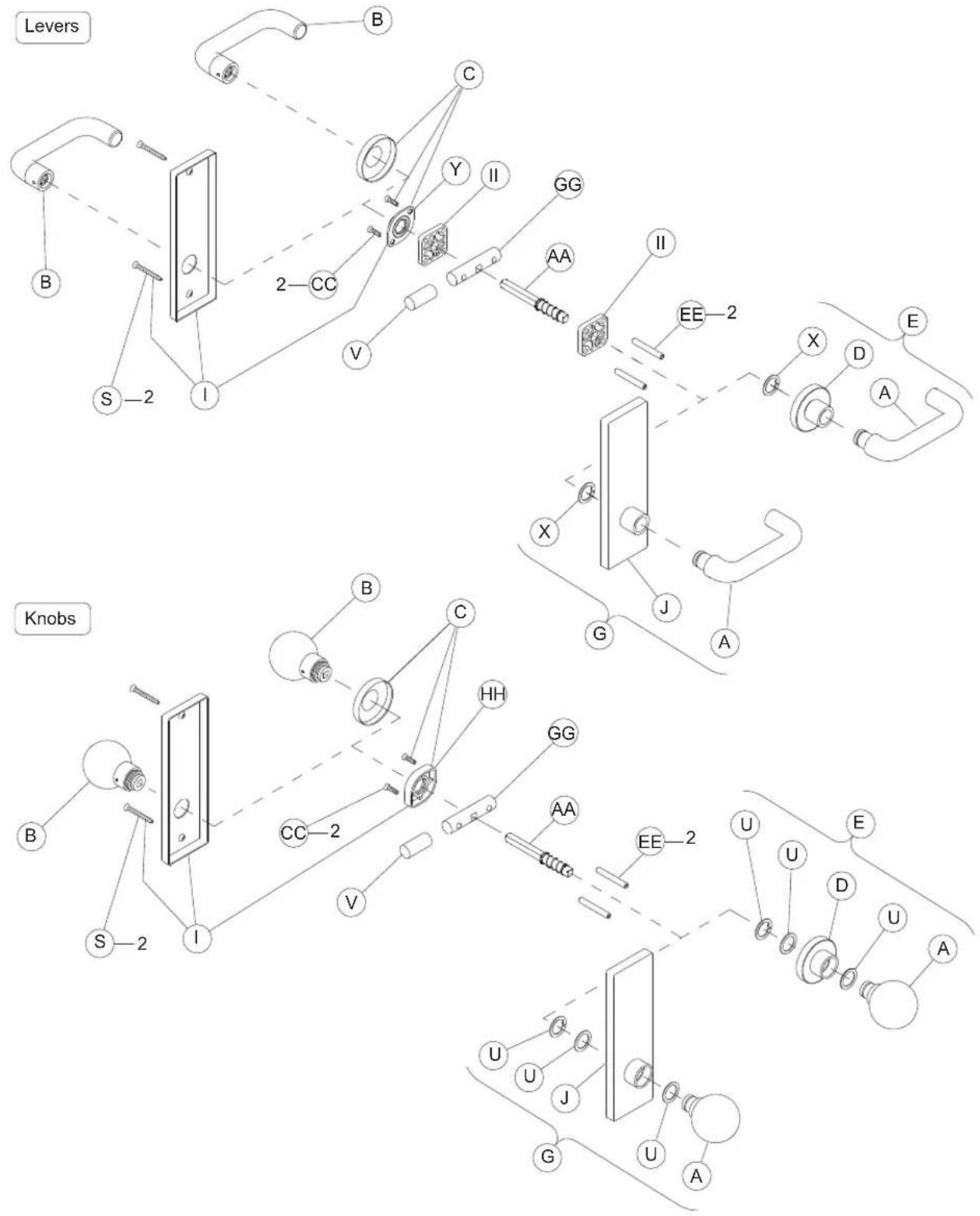
NOTE: Reinforcement required for metal door applications. See Schlage Door Preparation Manual & Template Guide.
Trim Assemblies
L400-Series Deadbolt Trim: L460, L462, L463, L464, L480, L496
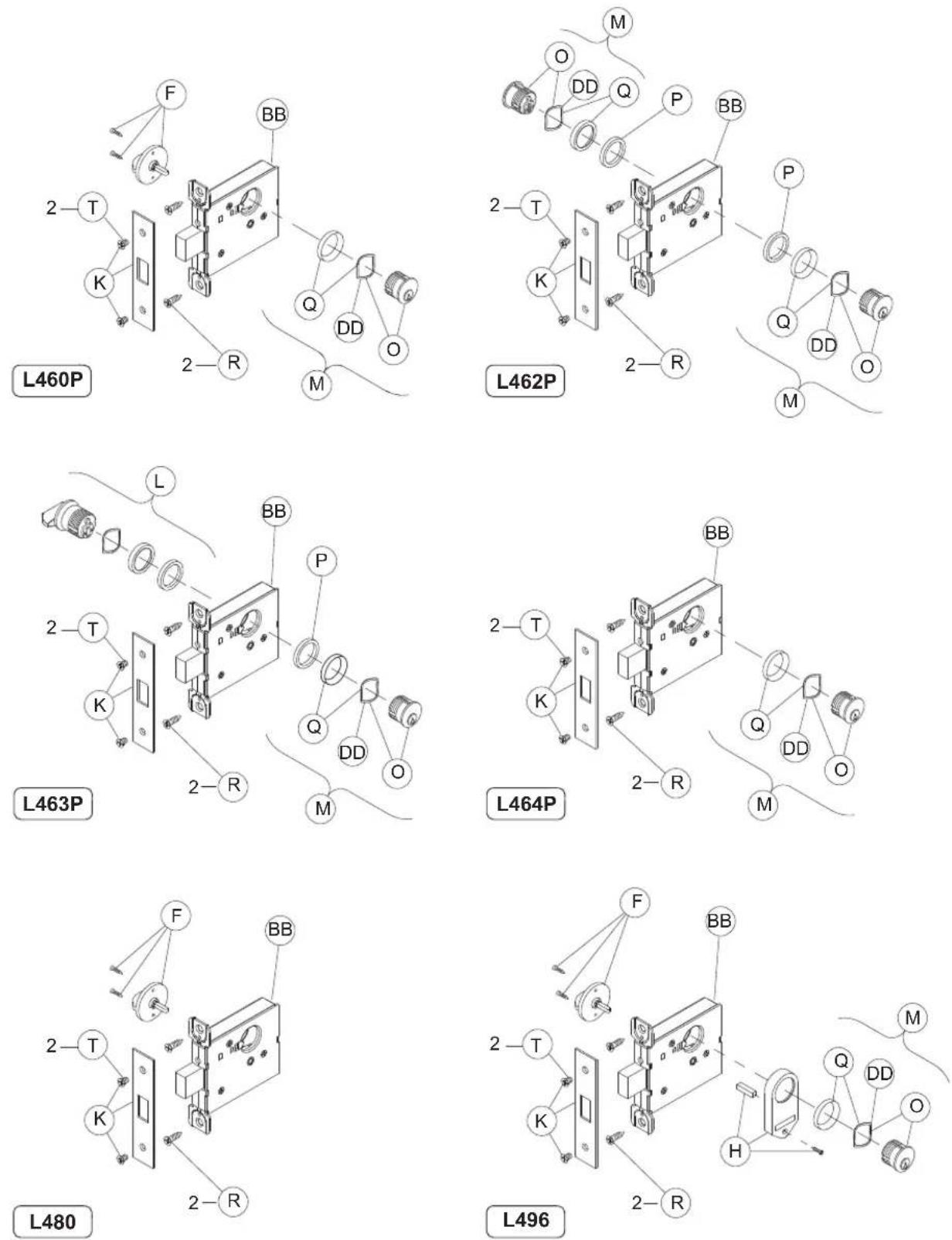
NOTE: Standard full face mortise cylinder shown.
Trim Assemblies
Passage Latch Trim: L9010

Trim Assemblies
Emergency Button x Turn Trim: L9040, LV9040, L9440, LV9440

NOTE: L9440 and LV9440 lock functions have latch and deadbolt. Lock case and armor front shown with latch only.
Trim Assemblies
Privacy x Turns Both Sides Trim: L9040 x XL11-446, LV9040 x XL11-446

Trim Assemblies
Coin Turn Outside x Turn Trim: L9044, LV9044, L9444, LV9444
Levers

Knobs

NOTE: L9444 and LV9444 lock functions have latch and deadbolt. Lock case and armor front shown with latch only.
Trim Assemblies
Cylinder x Turn Trim: L9050, LV9050, L9056, LV9056, L9453, LV9453, L9456, LV9456, L9473

NOTES: L9456, LV9456, and L9473 lock functions have a latch and deadbolt. Lock case and armor front shown with latch and auxiliary latch. L/LV9453 lock functions have a latch, auxiliary latch, and deadbolt. Lock case and armor front shown with latch and auxiliary latch only. Standard full face mortise cylinder shown.
Trim Assemblies
Double Cylinder Trim: L9060, LV9060, L9071, LV9071, L9077, LV9077, L9082, LV9082, L9457, LV9457, L9462 x XL11-886, L9466

NOTES: L9457, LV9457, and L9466 lock functions have a latch and deadbolt. Lock case and armor front shown with latch and auxiliary latch. L9462 x XL11-886 lock function has deadbolt only. Lock case and armor front shown with latch & auxiliary latch. Standard full face mortise cylinder shown.
Trim Assemblies
Cylinder Outside Trim: L9070, LV9070, L9076, LV9076, L9080, LV9080, L9080EL/EU, LV9080EL/EU, L9080EL/EU-RX, L9464 x XL11-886, L9465

NOTES: L9465 lock function has a latch and deadbolt. Lock case and armor front shown with latch and auxiliary latch. L9464 x XL11-886 lock function has deadbolt only. Lock case and armor front shown with latch and auxiliary latch. Standard full face mortise cylinder shown.
Trim Assemblies
Electrically Locked/Unlocked Both Sides Trim: L9082EL/EU

NOTE: Standard full face mortise cylinder shown.
Trim Assemblies
Active Double Dummy Trim: L9110 x XL11-741

Trim Assemblies
Single Dummy with Case Trim: L9175, L9177 (Discontinued)


Trim Assemblies
Double Dummy with Case Trim: L9176, L9178 (Discontinued)

Trim Assemblies
L9000-Series Deadbolt Trim: L9460, L9462, L9463, L9464

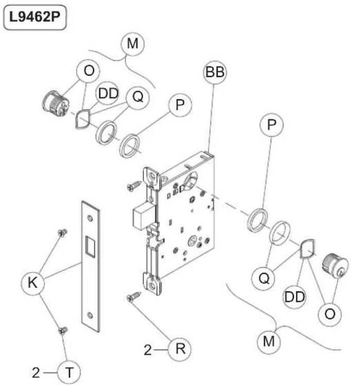


NOTE: Standard full face mortise cylinder shown.
Trim Assemblies
Deadbolt with Fixed Double Dummy Trim: L9460 x XL11-635

NOTE: Standard full face mortise cylinder shown.
Trim Assemblies
Fixed Outside x Turn Trim: L9460 x XL11-886, L9480, LV9480, L9485, LV9485

NOTES: L9460 x XL11-886 lock function has a deadbolt only. Lock case and armor front shown with latch, auxiliary latch, and deadbolt. Standard full face mortise cylinder shown
Trim Assemblies
Institution Deadbolt Trim: L9482 x XL11-543, LV9482 x XL11-543

NOTE: Standard full face mortise cylinder shown.
Trim Assemblies
Prison Lock Trim: L9485 x XL11-557

NOTE: Standard full face mortise cylinder shown.
Trim Assemblies
Hotel with Indicator Trim: L9486, LV9486, L9486 x L583-375, LV9486 x L583-375, L9496, LV9496

NOTES: L9496 and LV9496 lock functions have a latch and deadbolt. Lock case and armor front shown with latch, auxiliary latch, and deadbolt. Standard full face mortise cylinder shown.
Blank
Trim Assemblies Chart
† Not sold separately as a part.
* Available with rose trim only.
** Not available with N escutcheon.
NOTE: Standard cylinder part numbers are shown for cylinder function locks. See page 103-112 for other cylinder options.
Trim Assemblies Chart
† Not sold separately as a part.
* Available with rose trim only.
** Available with knob x rose trim only.
*** Not available with N escutcheon.
L9486 and LV9486 available with "Occupied" indicator option. Specify 09-611 x L583-375.
NOTE: Standard cylinder part numbers are shown for cylinder function locks. See page 103-112 for other cylinder options.
Trim Assemblies Chart
| P/N | Description | L0170 | L0172 | L460 | L462 | L463 | L464 | L480 | L496 | L9010 | L9040 | LV9040 | L9040/XL11-446** | LV9040/XL11-446** | L9044* | LV9050 | LV9050 | L9056 | LV9056 | L9060 | LV9060 | L9070 | LV9070 | L9071 | LV9071 | L9076 | LV9076 | L9077 | LV9077 | L9080 | LV9080 | L9080EL | LV9080EL | L9080EU | LV9080EU | L9080EL-RX | L9080EU-RX | L9082 | LV9082 | L9082EL | L9082EU | ||
| J | Outside Escutcheon & Bushing x Knob/Lever Except 93 Lever: | ||||||||||||||||||||||||||||||||||||||||||
| 09-636 L | & N x blank | • | • | ||||||||||||||||||||||||||||||||||||||||
| 09-636/XL-446 | L x thumbturn† | • | • | ||||||||||||||||||||||||||||||||||||||||
| 09-637 | L & N x emergency button | • | • | ||||||||||||||||||||||||||||||||||||||||
| 09-639 | L & N x full face cylinder | • | • | • | • | • | • | • | • | • | • | • | • | • | • | • | • | • | • | • | • | • | • | • | • | • | • | ||||||||||||||||
| 09-640 | L x concealed cylinder/ind. | ||||||||||||||||||||||||||||||||||||||||||
| 09-641 | L x full face cylinder, indicator | ||||||||||||||||||||||||||||||||||||||||||
| Outside N Escutcheon & Bushing x 93 Lever: | |||||||||||||||||||||||||||||||||||||||||||
| 09-650 | Blank | • | • | ||||||||||||||||||||||||||||||||||||||||
| 09-651 | Emergency button | • | • | • | • | ||||||||||||||||||||||||||||||||||||||
| 09-652 | Full face cylinder | • | • | • | • | • | • | • | • | • | • | • | • | • | • | • | • | • | • | • | • | • | • | • | • | • | • | ||||||||||||||||
| K | 11⁄4" Armor Front x Schlage Logo: | ||||||||||||||||||||||||||||||||||||||||||
| 09-661 | Blank | ||||||||||||||||||||||||||||||||||||||||||
| 09-662 | Latch | • | • | • | • | • | • | ||||||||||||||||||||||||||||||||||||
| 09-663 | Latch & aux. latch | • | • | • | • | • | • | • | • | • | • | • | • | • | • | • | • | • | • | • | • | • | • | • | • | • | • | ||||||||||||||||
| 09-664 | Latch & deadbolt | ||||||||||||||||||||||||||||||||||||||||||
| 09-665 | Deadbolt | ||||||||||||||||||||||||||||||||||||||||||
| 09-666 | Latch, aux. latch and deadbolt | ||||||||||||||||||||||||||||||||||||||||||
| 09-713 | Latch, aux. latch less UL stamp | • | • | • | • | • | • | • | • | • | • | • | • | • | • | • | • | ||||||||||||||||||||||||||
| 09-717 | L400-Series deadbolt | • | • | • | • | • | • | ||||||||||||||||||||||||||||||||||||
| L 09-905 | Classroom Turn & 11⁄2" blocking ring | • | |||||||||||||||||||||||||||||||||||||||||
| M | Full Face Cylinder with Compression Ring and Spring: | ||||||||||||||||||||||||||||||||||||||||||
| 20-001 | Straight cam | • | • | ||||||||||||||||||||||||||||||||||||||||
| 30-001 | Clover leaf cam | • | 2 | • | • | • | • | • | • | • | • | • | 2 | 2 | • | • | 2 | 2 | • | • | • | • | • | • | • | • | • | • | 2 | 2 | • | • | • | • | • | • | • | • | |||||
| 30-002 | Hotel (handed) | ||||||||||||||||||||||||||||||||||||||||||
† Not sold separately as a part.
* Available with rose trim only.
** Not available with N escutcheon.
NOTE: Standard cylinder part numbers are shown for cylinder function locks. See page 103-112 for other cylinder options.
Trim Assemblies Chart
| P/N Description | L9110/XL11-741 | L9175 | L9176 | L9177 (disc) | L9178 (disc) | L9440 | LV9440 | L9444* | LV9444* | L9453 | LV9453 | L9456 | LV9456 | L9457 | LV9457 | L9460 | L9460/XL11-635 | L9460/XL11-886 | L9462 | L9462/XL11-886 | L9463 | L9464 | L9464/XL11-886 | L9465 | L9466 | L9473 | L9480 | LV9480 | L9482/XL11-543 | LV9482/XL11-543 | L9485 | LV9485 | L9485/XL11-557** | L9486***% | LV9486***% | L9496 | LV9496 | ||
| J | Outside Escutcheon & Bushing x Knob/Lever Except 93 Lever: | ||||||||||||||||||||||||||||||||||||||
| 09-636 L | & N x blank | • | • | • | |||||||||||||||||||||||||||||||||||
| 09-636/XL-446 | L x thumbturn† | ||||||||||||||||||||||||||||||||||||||
| 09-637 | L & N x emergency button | • | • | ||||||||||||||||||||||||||||||||||||
| 09-639 | L & N x full face cylinder | • | • | • | • | • | • | • | • | • | • | • | • | • | • | • | • | • | • | ||||||||||||||||||||
| 09-640 | L x concealed cylinder/ind. | ||||||||||||||||||||||||||||||||||||||
| 09-641 | L x full face cylinder, indicator | • | • | • | • | ||||||||||||||||||||||||||||||||||
| Outside N Escutcheon & Bushing x 93 Lever: | |||||||||||||||||||||||||||||||||||||||
| 09-650 B | blank | • | • | ||||||||||||||||||||||||||||||||||||
| 09-651 | Emergency button | • | • | ||||||||||||||||||||||||||||||||||||
| 09-652 | Full face cylinder | • | • | • | • | • | • | • | • | • | • | • | • | • | |||||||||||||||||||||||||
| K | 11⁄4" Armor Front x Schlage Logo: | ||||||||||||||||||||||||||||||||||||||
| 09-661 B | blank | • | • | • | |||||||||||||||||||||||||||||||||||
| 09-662 L | latch | ||||||||||||||||||||||||||||||||||||||
| 09-663 | Latch & aux. latch | ||||||||||||||||||||||||||||||||||||||
| 09-664 | Latch & deadbolt | • | • | • | • | • | • | • | • | • | • | • | • | • | |||||||||||||||||||||||||
| 09-665 D | Deadbolt | • | • | • | • | • | • | • | • | ||||||||||||||||||||||||||||||
| 09-666 | Latch, aux. latch and deadbolt | • | • | • | • | • | • | • | • | • | • | • | |||||||||||||||||||||||||||
| 09-713 | Latch, aux. latch less UL stamp | ||||||||||||||||||||||||||||||||||||||
| 09-717 | L400-Series deadbolt | ||||||||||||||||||||||||||||||||||||||
| L O | 09-905 | Classroom Turn & 11⁄2" blocking ring | • | ||||||||||||||||||||||||||||||||||||
| M | Full Face Cylinder with Compression Ring and Spring: | ||||||||||||||||||||||||||||||||||||||
| 20-001 S | Straight cam | ||||||||||||||||||||||||||||||||||||||
| 30-001 C | over leaf cam | • | • | • | • | 2 | 2 | • | • | • | 2 | 2 | • | • | • | • | 2 | • | • | • | 2 | 2 | • | • | • | • | |||||||||||||
| 30-002 H | hotel (handed) | • | • | • | |||||||||||||||||||||||||||||||||||
† Not sold separately as a part.
* Available with rose trim only.
** Available with knob x rose trim only.
*** Not available with N escutcheon.
L9486 and LV9486 available with "Occupied" indicator option. Specify 09-611 x L583-375.
NOTE: Standard cylinder part numbers are shown for cylinder function locks. See page 103-112 for other cylinder options.
Trim Assemblies Chart
† Not sold separately as a part.
* Available with rose trim only.
** Not available with N escutcheon.
NOTE: Standard cylinder part numbers are shown for cylinder function locks. See page 103-112 for other cylinder options.
Trim Assemblies Chart
† Not sold separately as a part.
* Available with rose trim only.
** Available with knob x rose trim only.
*** Not available with N escutcheon.
L9486 and LV9486 available with "Occupied" indicator option. Specify 09-611 x L583-375.
NOTE: Standard cylinder part numbers are shown for cylinder function locks. See page 103-112 for other cylinder options.
Trim Assemblies Chart
| P/N Description | L0170 | L0172 | L460 | L462 | L463 | L464 | L480 | L496 | L9010 | L9040 | LV9040 | L9040/XL 11-446** | LV9040/XL 11-446** | L9044* | LV9044 | L9050 | LV9050 | L9056 | LV9056 | L9060 | LV9060 | L9070 | LV9070 | L9071 | LV9071 | L9076 | LV9076 | L9077 | LV9077 | L9080 | LV9080 | L9080EL | LV9080EL | L9080EU | LV9080EU | L9080EL-RX*** | L9080EU-RX*** | L9082 | LV9082 | L9082EL | L9082EU | |||
| BB | Assembled Lock Case: | |||||||||||||||||||||||||||||||||||||||||||
| L283-039 | Classroom holdback | • | • | |||||||||||||||||||||||||||||||||||||||||
| L283-062 | Privacy w/ deadbolt | |||||||||||||||||||||||||||||||||||||||||||
| L283-085 | L9082 EL | |||||||||||||||||||||||||||||||||||||||||||
| L283-086 | L9082 EU | • | ||||||||||||||||||||||||||||||||||||||||||
| L283-099 | L400 deadbolt | • | • | • | • | • | • | • | ||||||||||||||||||||||||||||||||||||
| L283-126 | Offi ce with simultaneous retraction | • | ||||||||||||||||||||||||||||||||||||||||||
| L283-131 | Passage | • | ||||||||||||||||||||||||||||||||||||||||||
| L283-132 | Privacy, L | • | • | • | ||||||||||||||||||||||||||||||||||||||||
| L283-133 | Offi ce, classroom, apartment security | • | • | • | • | |||||||||||||||||||||||||||||||||||||||
| L283-134 | Storeroom | • | ||||||||||||||||||||||||||||||||||||||||||
| L283-137 | Entrance | |||||||||||||||||||||||||||||||||||||||||||
| L283-138 | Corridor, classroom security x deadbolt | |||||||||||||||||||||||||||||||||||||||||||
| L283-139 | L9000 deadbolt | |||||||||||||||||||||||||||||||||||||||||||
| L283-140 | Closet, storeroom and dormitory | |||||||||||||||||||||||||||||||||||||||||||
| L283-141 | Hotel/Hotel x indicator | |||||||||||||||||||||||||||||||||||||||||||
| L283-142 | Electrically locked | • | • | |||||||||||||||||||||||||||||||||||||||||
| L283-143 | Electrically unlocked | • | • | |||||||||||||||||||||||||||||||||||||||||
| L283-144 | Single dummy with case | |||||||||||||||||||||||||||||||||||||||||||
| L283-145 | Double dummy with case | |||||||||||||||||||||||||||||||||||||||||||
| L283-146 | Institution | • | ||||||||||||||||||||||||||||||||||||||||||
| L283-170 | Offi ce, classroom, apartment security, LV† | • | • | • | • | • | • | • | • | • | • | • | • | • | • | • | • | • | • | • | • | • | • | • | • | • | ||||||||||||||||||
| L283-171 | Privacy, LV† | • | • | • | • | • | • | • | • | • | • | • | • | • | • | • | • | • | • | • | • | • | • | • | • | • | • | • | • | • | • | • | • | • | ||||||||||
| L283-172 | Classroom holdback, LV† | • | • | • | • | • | • | • | • | • | • | • | • | • | • | • | • | • | • | • | ||||||||||||||||||||||||
† Not sold separately as a part.
* Available with rose trim only.
** Available with knob x rose trim only.
*** Not available with N escutcheon.
NOTE: Standard cylinder part numbers are shown for cylinder function locks. See page 103-112 for other cylinder options.
Trim Assemblies Chart
| P/N Description | L9110/XL11-741 | L9175 | L9176 | L9177 (disc) | L9178 (disc) | L9440 | LV9440 | L9444* | LV9444* | L9453 | LV9453 | L9456 | LV9456 | L9457 | LV9457 | L9460 | L9460/XL11-635 | L9460/XL11-886 | L9462 | L9462/XL11-886 | L9463 | L9464 | L9464/XL11-886 | L9465 | L9466 | L9473 | L9480 | LV9480 | L9482/XL11-543 | LV9482/XL11-543 | L9485 | LV9485 | L9485/XL11-557** | L9486***% | LV9486***% | L9496 | LV9496 | |||
| BB | Assembled Lock Case: | |||||||||||||||||||||||||||||||||||||||
| L283-039 | Classroom holdback | |||||||||||||||||||||||||||||||||||||||
| L283-062 | Privacy w/ deadbolt | • | • | |||||||||||||||||||||||||||||||||||||
| L283-085 | L9082 EL | |||||||||||||||||||||||||||||||||||||||
| L283-086 | L9082 EU | |||||||||||||||||||||||||||||||||||||||
| L283-099 | L400 deadbolt | |||||||||||||||||||||||||||||||||||||||
| L283-126 | Offi ce with simultaneous retraction | |||||||||||||||||||||||||||||||||||||||
| L283-131 | Passage | |||||||||||||||||||||||||||||||||||||||
| L283-132 | Privacy, L | |||||||||||||||||||||||||||||||||||||||
| L283-133 | Offi ce, classroom, apartment security | |||||||||||||||||||||||||||||||||||||||
| L283-134 | Storeroom | |||||||||||||||||||||||||||||||||||||||
| L283-137 | Entrance | • | ||||||||||||||||||||||||||||||||||||||
| L283-138 | Corridor, classroom security x deadbolt | • | • | • | ||||||||||||||||||||||||||||||||||||
| L283-139 | L9000 deadbolt | • | • | • | • | |||||||||||||||||||||||||||||||||||
| L283-140 | Closet, storeroom and dormitory | • | • | • | ||||||||||||||||||||||||||||||||||||
| L283-141 | Hotel/Hotel x indicator | • | • | • | • | • | ||||||||||||||||||||||||||||||||||
| L283-142 | Electrically locked | |||||||||||||||||||||||||||||||||||||||
| L283-143 | Electrically unlocked | |||||||||||||||||||||||||||||||||||||||
| L283-144 | Single dummy with case | • | • | |||||||||||||||||||||||||||||||||||||
| L283-145 | Double dummy with case | • | • | |||||||||||||||||||||||||||||||||||||
| L283-146 | Institution | |||||||||||||||||||||||||||||||||||||||
| L283-170 | Offi ce, classroom, apartment / security, LV f† | |||||||||||||||||||||||||||||||||||||||
| L283-171 | Privacy, LV f | L283-172 | Classroom holdback, LV f | L283-172 | Classroom holdback, LV f | L283-172 | Classroom holdback, LV f | L283-172 | Classroom holdback, LV f | L283-172 | Classroom holdback, LV f | L283-172 | Classroom holdback, LV f | L283-172 | Class room holdback, LV f | L283-172 | Classroom holdback, LV f | L283-172 | Classroom holdback, LV f | L283-172 | Classroom holdback, LV f | L283-172 | Classroom holdback, LV f | L283-172 | Classroom holdback, LV f | L283-172 | ||||||||||||||
† Not sold separately as a part.
* Available with rose trim only.
** Available with knob x rose trim only.
*** Not available with N escutcheon.
※ L9486 and LV9486 available with "Occupied" indicator option. Specify 09-611 x L583-375.
NOTE: Standard cylinder part numbers are shown for cylinder function locks. See page 103-112 for other cylinder options.
Trim Assemblies Chart
| P/N Description | L0170 | L0172 | L460 | L462 | L463 | L464 | L480 | L496 | L9010 | L9040 | LV9040 | L9040/XL11-446** | LV9040/XL11-446** | L9044* | LV9044 | L9050 | LV9050 | L9056 | LV9056 | L9060 | LV9060 | L9070 | LV9070 | L9071 | LV9071 | L9076 | LV9076 | L9077 | LV9077 | L9080 | LV9080 | L9080EL | LV9080EL | L9080EU | LV9080EU | L9080EL-RX*** | L9080EU-RX*** | L9082 | LV9082 | L9082EL | L9082EU | ||
| BB | Assembled Lock Case: | ||||||||||||||||||||||||||||||||||||||||||
| L283-173 | Storeroom, LV† | • | |||||||||||||||||||||||||||||||||||||||||
| L283-174 | Electrically locked, LV† | • | |||||||||||||||||||||||||||||||||||||||||
| L283-175 | Electrically unlocked, LV† | • | |||||||||||||||||||||||||||||||||||||||||
| L283-176 | Entrance, LV† | ||||||||||||||||||||||||||||||||||||||||||
| L283-177 | Corridor, classroom security x deadbolt, LV† | ||||||||||||||||||||||||||||||||||||||||||
| L283-178 | Hotel/Hotel x indicator, LV† | ||||||||||||||||||||||||||||||||||||||||||
| L283-180 | Offi ce with simultaneous retraction, LV† | • | |||||||||||||||||||||||||||||||||||||||||
| L283-181 | Privacy with deadbolt, LV† | ||||||||||||||||||||||||||||||||||||||||||
| L283-182 | Institution, LV† | • | |||||||||||||||||||||||||||||||||||||||||
| L283-183 | Institution deadbolt, LV† | ||||||||||||||||||||||||||||||||||||||||||
| L283-146 | Institution deadbolt† | ||||||||||||||||||||||||||||||||||||||||||
| XL11-557 | Prison† | ||||||||||||||||||||||||||||||||||||||||||
| L283-139 | Deadbolt with fi xed trim† | ||||||||||||||||||||||||||||||||||||||||||
| XL11-741 | Double dummy with active knob/ lever† | ||||||||||||||||||||||||||||||||||||||||||
| L283-139 | Deadbolt retract x inside knob/lever† | ||||||||||||||||||||||||||||||||||||||||||
† Not sold separately as a part.
* Available with rose trim only.
** Available with knob x rose trim only.
*** Not available with N escutcheon.
NOTE: Standard cylinder part numbers are shown for cylinder function locks. See page 103-112 for other cylinder options.
Trim Assemblies Chart
| P/N Description | L9110/XL11-741 | L9175 | L9176 | L9177 (disc) | L9178 (disc) | L9440 | LV9440 | L9444* | LV9444* | L9453 | LV9453 | L9456 | LV9456 | L9457 | LV9457 | L9460 | L9460/XL11-635 | L9460/XL11-886 | L9462 | L9462/XL11-886 | L9463 | L9464 | L9464/XL11-886 | L9465 | L9466 | L9473 | L9480 | LV9480 | L9482/XL11-543 | LV9482/XL11-543 | L9485 | LV9485 | L9485/XL11-557** | L9486***% | LV9486***% | L9496 | LV9496 | ||
| BB | Assembled Lock Case: | ||||||||||||||||||||||||||||||||||||||
| L283-173 | Storeroom, LV† | ||||||||||||||||||||||||||||||||||||||
| L283-174 | Electrically locked, LV† | ||||||||||||||||||||||||||||||||||||||
| L283-175 | Electrically unlocked, LV† | ||||||||||||||||||||||||||||||||||||||
| L283-176 | Entrance, LV† | • | |||||||||||||||||||||||||||||||||||||
| L283-177 | Corridor, classroom security x deadbolt, LV† | • | • | • | |||||||||||||||||||||||||||||||||||
| L283-178 | Hotel/Hotel x indicator, LV† | • | • | • | |||||||||||||||||||||||||||||||||||
| L283-180 | Offi ce with simultaneous retraction, LV† | ||||||||||||||||||||||||||||||||||||||
| L283-181 | Privacy with deadbolt, LV† | • | • | ||||||||||||||||||||||||||||||||||||
| L283-182 | Institution, LV† | ||||||||||||||||||||||||||||||||||||||
| L283-183 | Institution deadbolt, LV† | • | |||||||||||||||||||||||||||||||||||||
| L283-146 | Institution deadbolt† | • | |||||||||||||||||||||||||||||||||||||
| XL11-557 | Prison† | • | |||||||||||||||||||||||||||||||||||||
| L283-139 | Deadbolt with fi xed trim† | • | |||||||||||||||||||||||||||||||||||||
| XL11-741 | Double dummy with active knob/ lever† | • | |||||||||||||||||||||||||||||||||||||
| L283-139 | Deadbolt retract x inside knob/lever† | • | • | • | |||||||||||||||||||||||||||||||||||
† Not sold separately as a part.
* Available with rose trim only.
** Available with knob x rose trim only.
*** Not available with N escutcheon.
※ L9486 and LV9486 available with "Occupied" indicator option. Specify 09-611 x L583-375.
NOTE: Standard cylinder part numbers are shown for cylinder function locks. See page 103-112 for other cylinder options.
Trim Assemblies Chart
| P/N Description | L0170 | L0172 | L460 | L462 | L463 | L464 | L480 | L496 | L9010 | L9040 | LV9040 | L9040/XL11-446** | LV9040/XL11-446** | L9044* | LV9044 | L9050 | LV9050 | L9056 | LV9056 | L9060 | LV9060 | L9070 | LV9070 | L9071 | LV9071 | L9076 | LV9076 | L9077 | LV9077 | L9080 | LV9080 | L9080EL | LV9080EL | L9080EU | LV9080EU | L9080EL-RX*** | L9080EU-RX*** | L9082 | LV9082 | L9082EL | L9082EU | ||
| CC | Assembled Lock Case: | ||||||||||||||||||||||||||||||||||||||||||
| F506-237 | Wood doors x L escutcheon | 2 | |||||||||||||||||||||||||||||||||||||||||
| L583-066 | Wood/metal doors x rose/ Escutcheon x knob/lever except single dummy | 2 | 2 | 2 | 2 | 2 | 2 | 2 | 2 | 2 | 2 | 2 | 2 | 2 | 2 | 2 | 2 | 2 | 2 | 2 | |||||||||||||||||||||||
| L583-290 | Wood/metal doors x rose/ Escutcheon x lever | 2 | |||||||||||||||||||||||||||||||||||||||||
| L583-291 | Wood/metal doors x rose/ Escutcheon x knob | 2 | |||||||||||||||||||||||||||||||||||||||||
| DD L | 583-195 | Compression spring | • | 2 | • | • | • | • | • | • | • | 2 | 2 | • | • | 2 | 2 | • | • | 2 | 2 | • | • | • | • | • | • | • | • | 2 | 2 | 2 | 2 | ||||||||||
| EE | L583-212 | Mounting posts, L | 2 | 2 | 2 | 2 | 2 | 2 | 2 | 2 | 2 | 2 | 2 | 2 | 2 | 2 | 2 | 2 | 2 | 2 | 2 | ||||||||||||||||||||||
| L583-497 | Mounting posts, LV | 2 | 2 | 2 | 2 | 2 | 2 | 2 | 2 | 2 | 2 | 2 | 2 | 2 | 2 | ||||||||||||||||||||||||||||
| FF L | 583-233 | Emergency turn | • | • | |||||||||||||||||||||||||||||||||||||||
| GG L | 583-286 | Dummy mounting bar | • | • | |||||||||||||||||||||||||||||||||||||||
| HH L | 583-321 | I/S Knob mounting plate | • | • | • | • | • | • | • | • | • | • | • | • | • | • | • | • | • | • | • | ||||||||||||||||||||||
| II L | 583-322 Lever spacer | • | 2 | • | 2 | ||||||||||||||||||||||||||||||||||||||
| JJ | 10-091 | Armor strike | |||||||||||||||||||||||||||||||||||||||||
* Available with rose trim only.
** Available with knob x rose trim only.
*** Not available with N escutcheon.
NOTE: Standard cylinder part numbers are shown for cylinder function locks. See page 103-112 for other cylinder options.
Trim Assemblies Chart
| P/N Description | L9110/XL11-741 | L9175 | L9176 | L9177 (disc) | L9178 (disc) | L9440 | LV9440 | L9444* | LV9444* | L9453 | LV9453 | L9456 | LV9456 | L9457 | LV9457 | L9460 | L9460/XL11-635 | L9460/XL11-886 | L9462 | L9462/XL11-886 | L9463 | L9464 | L9464/XL11-886 | L9465 | L9466 | L9473 | L9480 | LV9480 | L9482/XL11-543 | LV9482/XL11-543 | L9485 | LV9485 | L9485/XL11-557** | L9486***% | LV9486***% | L9496 | LV9496 | ||
| CC | Mounting Plate Screws: | ||||||||||||||||||||||||||||||||||||||
| F506-237 | Wood doors x L escutcheon | ||||||||||||||||||||||||||||||||||||||
| L583-066 | Wood/metal doors x rose/ Escutcheon x knob/lever except single dummy | 2 | 2 | 2 | 2 | 2 | 2 | 2 | 2 | 2 | 2 | 2 | 2 | 2 | 2 | 2 | 2 | 2 | 2 | 2 | 2 | 2 | 2 | ||||||||||||||||
| L583-290 | Wood/metal doors x rose/ Escutcheon x lever | 2 | 2 | ||||||||||||||||||||||||||||||||||||
| L583-291 | Wood/metal doors x rose/ Escutcheon x knob | 2 | 2 | ||||||||||||||||||||||||||||||||||||
| DD | L583-195 | Compression spring | • | • | • | • | 2 | 2 | • | • | • | 2 | 2 | • | • | • | • | 2 | • | • | • | 2 | 2 | • | • | • | • | • | • | ||||||||||
| EE | L583-212 | Mounting posts, L | 2 | 2 | 2 | 2 | 2 | 2 | 2 | 2 | 2 | 2 | 2 | 2 | 2 | 2 | 2 | 2 | 2 | 2 | 2 | ||||||||||||||||||
| L583-497 | Mounting posts, LV | 2 | 2 | 2 | 2 | 2 | 2 | 2 | 2 | 2 | 2 | ||||||||||||||||||||||||||||
| FF | L583-233 | Emergency turn | • | • | |||||||||||||||||||||||||||||||||||
| GG | L583-286 | Dummy mounting bar | |||||||||||||||||||||||||||||||||||||
| HH | L583-321 | I/S Knob mounting plate | • | • | • | • | • | • | • | • | • | • | • | • | • | • | • | • | • | • | • | • | • | • | • | • | • | • | |||||||||||
| II L5 | 83-322 Lever spacer | • | 2 | • | 2 | 2 | • | • | • | • | 2 | • | 2 | • | • | ||||||||||||||||||||||||
| JJ | 10-091 | Armor strike | • | • | |||||||||||||||||||||||||||||||||||
* Available with rose trim only.
** Available with knob x rose trim only.
*** Not available with N escutcheon.
L9486 and LV9486 available with "Occupied" indicator option. Specify 09-611 x L583-375.
NOTE: Standard cylinder part numbers are shown for cylinder function locks. See page 103-112 for other cylinder options.
Lock Case Assemblies
L460, L462, L463, L464, L480, L496
Assembled Lock Case L283-099

| Number | Description Part | Number |
| 3 | Deadbolt L283-003 | |
| 10 | Cylinder Plate & Screw L283-055 | |
| 14 | L400 Lock Case L283-128 | |
| 27 | Turn Hub L583-029 | |
| 30 | Turn Hub Spring L583-035 | |
| 51 | 1 1/4 " Faceplate Tab | L583-426 |
| 52 | Case Cover Screws L583-454 | |
| 53 | Cylinder Retainer Screw L583-481 | |
| 55 | Cylinder Retainer L583-490 | |
| 56 | Screw Plate L583-492 | |
| 57 | Lock Case Cover | L583-494 |


NOTE: Lock case assembly shown for LH and LHR doors.
Lock Case Assemblies
L9010
Assembled Lock Case L283-131

| Number | Description | Part Number |
| 6 | Latchbolt L283-008 | |
| 13 | L9000 Lock Case L283-112 | |
| 17 | Retractor Hub L583-019 | |
| 18 | Hub Spacer L583-020 | |
| 19 | Retractor Lever L583-021 | |
| 20 | Retractor Rocker L583-022 | |
| 21 | Blocking Plate L583-023 | |
| 22 | Retractor Link L583-024 | |
| 23 | Retractor Crank L583-025 | |
| 24 | Hub Spring L583-026 | |
| 25 | Fire Door Fuse L583-027 | |
| 26 | Fire Door Catch L583-028 | |
| 31 | Aux liary Bar Guide L583-038 | |
| 51 | 1 1/4 " Faceplate Tab | L583-426 |
| 52 | Case Cover Screws | L583-454 |
| 58 | Lock Case Cover | L583-496 |

** See "Assembly of Lock Case Parts" on page 87.
NOTE: Lock case assembly shown for LH and LHR doors.
Lock Case Assemblies
L9040, L9040 x XL11-446, L9044
Assembled Lock Case L283-132

| Number | Description | Part Number |
| 6 | Latchbolt L283-008 | |
| 13 | L9000 Lock Case L283-112 | |
| 17 | Retractor Hub L583-019 | |
| 18 | Hub Spacer L583-020 | |
| 19 | Retractor Lever L583-021 | |
| 20 | Retractor Rocker L583-022 | |
| 21 | Blocking Plate L583-023 | |
| 22 | Retractor Link L583-024 | |
| 23 | Retractor Crank L583-025 | |
| 24 | Hub Spring L583-026 | |
| 25 | Fire Door Fuse L583-027 | |
| 26 | Fire Door Catch L583-028 | |
| 27 | Turn Hub L583-029 | |
| 30 | Turn Hub Spring L583-035 | |
| 31 | Auxiliary Bar Guide L583-038 | |
| 34 | Locking Catch L583-045 | |
| 36 | Locking Link L583-048 | |
| 38 | Link Pin L583-050 | |
| 43 | Simultaneous Retractor L583-058 | |
| 51 | 11/4 " Faceplate Tab | L583-426 |
| 52 | Case Cover Screws L583-454 | |
| 54 | Lock Handing Screw L583-485 | |
| 58 | Lock Case Cover L583-496 |

** See "Assembly of Lock Case Parts" on page 87.
NOTE: Lock case assembly shown for LH and LHR doors. See page 118 for instructions on changing the lock hand.
Lock Case Assemblies
LV9040, LV9040 x XL11-446, LV9044
Assembled Lock Case L283-171

| Number | Description | Part Number |
| 6 Latchbolt L283-008 | ||
| 13 L9000 Lock Case L283-112 | ||
| 22 Retractor Link L583-024 | ||
| 24 Hub Spring L583-026 | ||
| 25 Fire Door Fuse L583-027 | ||
| 26 Fire Door Catch L583-028 | ||
| 27 Turn Hub L583-029 | ||
| 30 Turn Hub Spring L583-035 | ||
| 31 Auxiliary Bar Guide L583-038 | ||
| 36 Locking Link L583-048 | ||
| 38 Link Pin L583-050 | ||
| 43 Simultaneous Retractor L583-058 | ||
| 51 1 1/4 " Faceplate Tab L583-426 | ||
| 52 Case Cover Screws L583-454 | ||
| 54 Lock Handing Screw L583-485 | ||
| 58 Lock Case Cover L583-496 | ||
| 60 Retractor Lever Assy L283-147 | ||
| 61 Crank Retractor L583-383 | ||
| 62 Bottom Hub L583-386 | ||
| 63 Top Hub L583-387 | ||
| 64 Retractor Catch L583-345 | ||

** See "Assembly of Lock Case Parts" on page 87.
NOTE: Lock case assembly shown for RH and RHR doors. See page 118 for instructions on changing the lock hand.
Lock Case Assemblies
L9050, L9060, L9070, L9071
Assembled Lock Case L283-133

| Number | Description | Part Number |
| 5 | Auxiliary Latchbolt L283-006 | |
| 6 | Latch bolt L283-008 | |
| 10 | Cylinder Plate & Screw L283-055 | |
| 13 | L9000 Lock Case L283-112 | |
| 17 | Retractor Hub L583-019 | |
| 18 | Hub Spacer L583-020 | |
| 19 | Retractor Lever L583-021 | |
| 20 | Retractor Rocker L583-022 | |
| 21 | Blocking Plate L583-023 | |
| 22 | Retractor Link L583-024 | |
| 23 | Retractor Crank L583-025 | |
| 24 | Hub Spring L583-026 | |
| 25 | Fire Door Fuse L583-027 | |
| 26 | Fire Door Catch L583-028 | |
| 27 | Turn Hub L583-029 | |
| 30 | Turn Hub Spring L583-035 | |
| 33 | Stop Spring L583-044 | |
| 34 | Locking Catch L583-045 | |
| 36 | Locking Link L583-048 | |
| 38 | Link Pin L583-050 | |
| 39 | Transfer Lever L583-051 | |
| 47 | Transfer Lifter L583-156 | |
| 50 | Auxiliary Stop L583-196 | |
| 51 | 1 1/4 " Faceplate Tab L583-426 | |
| 52 | Case Cover Screws L583-454 | |
| 53 | Cylinder Retainer Screw L583-481 | |
| 54 | Lock Handing Screw L583-485 | |
| 55 | Cylinder Retainer L583-490 | |
| 56 | Screw Plate L583-492 | |
| 58 | Lock Case Cover L583-496 |

** See "Assembly of Lock Case Parts" on page 87.
NOTE: Lock case assembly shown for LH and LHR doors. See page 118 for instructions on changing the lock hand.
Lock Case Assemblies
LV9050, LV9060, LV9070, LV9071
Assembled Lock Case L283-170

** See "Assembly of Lock Case Parts" on page 87.
NOTE: Lock case assembly shown for RH and RHR doors. See page 118 for instructions on changing the lock hand.
Lock Case Assemblies
L9056
Assembled Lock Case L283-126

| Number | Description | Part Number |
| 5 | Auxiliary Latchbolt L283-006 | |
| 6 | Latchbolt L283-008 | |
| 10 | Cylinder Plate & Screw L283-055 | |
| 13 | L9000 Lock Case L283-112 | |
| 17 | Retractor Hub L583-019 | |
| 18 | Hub Spacer L583-020 | |
| 19 | Retractor Lever L583-021 | |
| 20 | Retractor Rocker L583-022 | |
| 21 | Blocking Plate L583-023 | |
| 22 | Retractor Link L583-024 | |
| 23 | Retractor Crank L583-025 | |
| 24 | Hub Spring L583-026 | |
| 25 | Fire Door Fuse L583-027 | |
| 26 | Fire Door Catch L583-028 | |
| 27 | Turn Hub L583-029 | |
| 30 | Turn Hub Spring L583-035 | |
| 33 | Stop Spring L583-044 | |
| 34 | Locking Catch L583-045 | |
| 36 | Locking Link L583-048 | |
| 38 | Link Pin L583-050 | |
| 39 | Transfer Lever L583-051 | |
| 43 | Simultaneous Retractor L583-058 | |
| 47 | Transfer Lifter L583-156 | |
| 50 | Auxiliary Stop L583-196 | |
| 51 | 11/4 " Faceplate Tab L583-426 | |
| 52 | Case Cover Screws L583-454 | |
| 53 | Cylinder Retainer Screw L583-481 | |
| 54 | Lock Handing Screw L583-485 | |
| 55 | Cylinder Retainer L583-490 | |
| 56 | Screw Plate L583-492 | |
| 58 | Lock Case Cover L583-496 |

** See "Assembly of Lock Case Parts" on page 87.
NOTE: Lock case assembly shown for LH and LHR doors. See page 118 for instructions on changing the lock hand.
Lock Case Assemblies
LV9056
Assembled Lock Case L283-180

| Number | Description | Part Number |
| 5 | Auxiliary Latchbolt L283-006 | |
| 6 | Latch bolt L283-008 | |
| 10 | Cylinder Plate & Screw L283-055 | |
| 13 | L9000 Lock Case L283-112 | |
| 22 | Retractor Link L583-024 | |
| 24 | Hub Spring L583-026 | |
| 25 | Fire Door Fuse L583-027 | |
| 26 | Fire Door Catch L583-028 | |
| 27 | Turn Hub L583-029 | |
| 30 | Turn Hub Spring L583-035 | |
| 33 | Stop Spring L583-044 | |
| 36 | Locking Link L583-048 | |
| 38 | Link Pin L583-050 | |
| 39 | Transfer Lever L583-051 | |
| 43 | Simultaneous Retractor L583-058 | |
| 47 | Transfer Lifter L583-156 | |
| 50 | Auxiliary Stop L583-196 | |
| 51 | 11/4 " Faceplate Tab L583-426 | |
| 52 | Case Cover Screws L583-454 | |
| 53 | Cylinder Retainer Screw L583-481 | |
| 54 | Lock Handing Screw L583-485 | |
| 55 | Cylinder Retainer L583-490 | |
| 56 | Screw Plate L583-492 | |
| 58 | Lock Case Cover L583-496 | |
| 60 | Retractor Lever Assy L283-147 | |
| 61 | Crank Retractor L583-383 | |
| 62 | Bottom Hub L583-386 | |
| 63 | Top Hub L583-387 | |
| 64 | Retractor Catch L583-345 |

** See "Assembly of Lock Case Parts" on page 87.
NOTE: Lock case assembly shown for RH and RHR doors. See page 118 for instructions on changing the lock hand.
Lock Case Assemblies
L9076, L9077
Assembled Lock Case L283-039

| Number | Description | Part Number |
| 5 | Auxiliary Latchbolt L283-006 | |
| 7 | Locking Link L283-010 | |
| 8 | Latchbolt L283-049 | |
| 10 | Cylinder Plate & Screw L283-055 | |
| 13 | L9000 Lock Case L283-112 | |
| 17 | Retractor Hub L583-019 | |
| 18 | Hub Spacer L583-020 | |
| 19 | Retractor Lever L583-021 | |
| 20 | Retractor Rocker L583-022 | |
| 21 | Blocking Plate L583-023 | |
| 22 | Retractor Link L583-024 | |
| 23 | Retractor Crank L583-025 | |
| 24 | Hub Spring L583-026 | |
| 25 | Fire Door Fuse L583-027 | |
| 26 | Fire Door Catch L583-028 | |
| 27 | Turn Hub L583-029 | |
| 30 | Turn Hub Spring L583-035 | |
| 33 | Stop Spring L583-044 | |
| 34 | Locking Catch L583-045 | |
| 38 | Link Pin L583-050 | |
| 39 | Transfer Lever L583-051 | |
| 47 | Transfer Lifter L583-156 | |
| 48 | Holdback Dog L583-174 | |
| 49 | Dog Spring L583-192 | |
| 50 | Auxiliary Stop L583-196 | |
| 51 | 1 1/4 " Faceplate Tab L583-426 | |
| 52 | Case Cover Screws L583-454 | |
| 53 | Cylinder Retainer Screw L583-481 | |
| 54 | Lock Handing Screw L583-485 | |
| 55 | Cylinder Retainer L583-490 | |
| 56 | Screw Plate L583-492 | |
| 58 | Lock Case Cover L583-496 |

** See "Assembly of Lock Case Parts" on page 87.
NOTE: Lock case assembly shown for LH and LHR doors. See page 118 for instructions on changing the lock hand.
Lock Case Assemblies
LV9076, LV9077
Assembled Lock Case L283-172
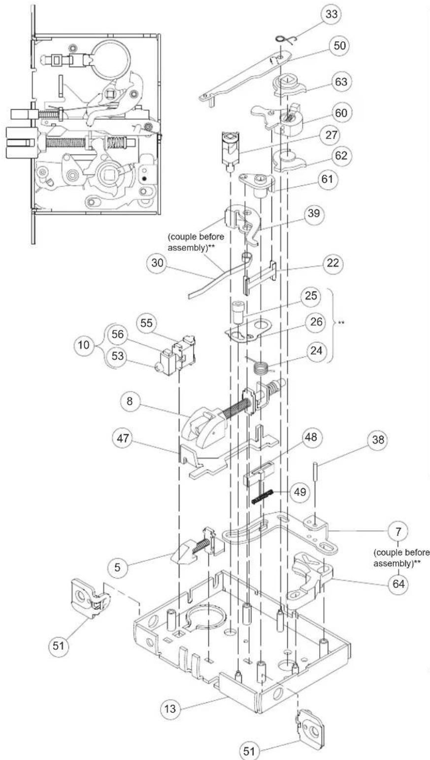
| Number | Description | Part Number |
| 5 | Auxiliary Latchbolt L283-006 | |
| 7 | Locking Link L283-010 | |
| 8 | Latchbolt L283-049 | |
| 10 | Cylinder Plate & Screw L283-055 | |
| 13 | L9000 Lock Case L283-112 | |
| 22 | Retractor Link L583-024 | |
| 24 | Hub Spring L583-026 | |
| 25 | Fire Door Fuse L583-027 | |
| 26 | Fire Door Catch L583-028 | |
| 27 | Turn Hub L583-029 | |
| 30 | Turn Hub Spring L583-035 | |
| 33 | Stop Spring L583-044 | |
| 38 | Link Pin L583-050 | |
| 39 | Transfer Lever L583-051 | |
| 47 | Transfer Lifter L583-156 | |
| 48 | Holdback Dog L583-174 | |
| 49 | Dog Spring L583-192 | |
| 50 | Auxiliary Stop L583-196 | |
| 51 | 11/4 " Faceplate Tab L583-426 | |
| 52 | Case Cover Screws L583-454 | |
| 53 | Cylinder Retainer Screw L583-481 | |
| 54 | Lock Handing Screw L583-485 | |
| 55 | Cylinder Retainer L583-490 | |
| 56 | Screw Plate L583-492 | |
| 58 | Lock Case Cover L583-496 | |
| 60 | Retractor Lever Assy L283-147 | |
| 61 | Crank Retractor L583-383 | |
| 62 | Bottom Hub L583-386 | |
| 63 | Top Hub L583-387 | |
| 64 | Retractor Catch L583-345 |

** See "Assembly of Lock Case Parts" on page 87.
NOTE: Lock case assembly shown for RH and RHR doors. See page 118 for instructions on changing the lock hand.
Lock Case Assemblies
L9080
Assembled Lock Case L283-134

| Number | Description | Part Number |
| 5 | Auxiliary Latchbolt L283-006 | |
| 6 | Latchbolt L283-008 | |
| 10 | Cylinder Plate & Screw L283-055 | |
| 13 | L9000 Lock Case L283-112 | |
| 15 | Standoff Post L583-004 | |
| 17 | Retractor Hub L583-019 | |
| 18 | Hub Spacer L583-020 | |
| 19 | Retractor Lever L583-021 | |
| 20 | Retractor Rocker L583-022 | |
| 21 | Blocking Plate L583-023 | |
| 22 | Retractor Link L583-024 | |
| 23 | Retractor Crank L583-025 | |
| 24 | Hub Spring L583-026 | |
| 25 | Fire Door Fuse L583-027 | |
| 26 | Fire Door Catch L583-028 | |
| 33 | Stop Spring L583-044 | |
| 34 | Locking Catch L583-045 | |
| 39 | Transfer Lever L583-051 | |
| 41 | Catch Pin L583-056 | |
| 50 | Auxiliary Stop L583-196 | |
| 51 | 11/4" Faceplate Tab L583-426 | |
| 52 | Case Cover Screws L583-454 | |
| 53 | Cylinder Retainer Screw L583-481 | |
| 54 | Lock Handing Screw L583-485 | |
| 55 | Cylinder Retainer L583-490 | |
| 56 | Screw Plate L583-492 | |
| 58 | Lock Case Cover L583-496 |

** See "Assembly of Lock Case Parts" on page 87.
NOTE: Lock case assembly shown for LH and LHR doors. See page 118 for instructions on changing the lock hand.
Lock Case Assemblies
LV9080
Assembled Lock Case L283-173

| Number | Description | Part Number |
| 5 | Auxiliary Latchbolt L283-006 | |
| 6 | Latchbolt L283-008 | |
| 10 | Cylinder Plate & Screw L283-055 | |
| 13 | L9000 Lock Case L283-112 | |
| 15 | Standoff Post L583-004 | |
| 22 | Retractor Link L583-024 | |
| 24 | Hub Spring L583-026 | |
| 25 | Fire Door Fuse L583-027 | |
| 26 | Fire Door Catch L583-028 | |
| 33 | Stop Spring L583-044 | |
| 39 | Transfer Lever L583-051 | |
| 41 | Catch Pin L583-056 | |
| 50 | Auxiliary Stop L583-196 | |
| 51 | 1 1/4 " Faceplate Tab L583-426 | |
| 52 | Case Cover Screws L583-454 | |
| 53 | Cylinder Retainer Screw L583-481 | |
| 54 | Lock Handing Screw L583-485 | |
| 55 | Cylinder Retainer L583-490 | |
| 56 | Screw Plate L583-492 | |
| 58 | Lock Case Cover L583-496 | |
| 60 | Retractor Lever Assy L583-147 | |
| 61 | Crank Retractor L583-383 | |
| 62 | Bottom Hub L583-386 | |
| 63 | Top Hub L583-387 | |
| 64 | Retractor Catch L583-345 |

** See "Assembly of Lock Case Parts" on page 87.
NOTE: Lock case assembly shown for RH and RHR doors. See page 118 for instructions on changing the lock hand.
Lock Case Assemblies
L9080EL, L9080EL-RX
Assembled Lock Case L283-142

| Number Description | Part Number | |
| 1 Lock | O-Ring 36-080 | |
| 2 Lock | Bushing K510-842 | |
| 5 Auxiliary Latchbolt L283-006 | ||
| 6 Latchbolt L283-008 | ||
| 9 Solenoid & Driver L283-053 | ||
| 10 Cylinder Plate & Screw L283-055 | ||
| 13 L9000 Lock Case L283-112 | ||
| 15 Standoff Post L583-004 | ||
| 17 Retractor Hub L583-019 | ||
| 18 Hub | Spacer L583-020 | |
| 19 Retractor Lever | L583-021 | |
| 20 Retractor Rocker | L583-022 | |
| 21 Blocking Plate | L583-023 | |
| 22 Retractor Link L583-024 | ||
| 23 Retractor Crank | L583-025 | |
| 24 Hub | Spring L583-026 | |
| 25 Fire | Door Fuse L583-027 | |
| 26 Fire | Door Catch L583-028 | |
| 32 Locking Catch | L583-043 | |
| 33 Stop | Spring L583-044 | |
| 38 Link | Pin L583-050 | |
| 39 Transfer Lever | L583-051 | |
| 44 Spring Retainer | L583-063 | |
| 45 Solenoid Spring | L583-064 | |
| 46 Electrified Link | L583-065 | |
| 50 Auxiliary Stop | L583-196 | |
| 51 | 1 1/4 " Faceplate Tab | L583-426 |
| 52 Case | Cover Screws L583-454 | |
| 53 Cylinder Retainer Screw | L583-481 | |
| 54 Lock | Handing Screw L583-485 | |
| 55 Cylinder Retainer | L583-490 | |
| 56 Screw Plate | L583-492 | |
| 58 Lock | Case Cover L583-496 | |
| 59 Lock | Case with Microswitch* n/a | |

* See "Request to Exit (RX) Feature" on page 116.
** See "Assembly of Lock Case Parts" on page 87.
NOTE: Lock case assembly shown for LH and LHR doors. See page 118 for instructions on changing the lock hand.
Lock Case Assemblies
LV9080EL
Assembled Lock Case L283-174

| Number Description | Part Number | |
| 1 EL Lock O-Ring 36-080 | ||
| 2 EL Lock Bushing K510-842 | ||
| 5 Auxiliary Latchbolt L283-006 | ||
| 6 Latchbolt L283-008 | ||
| 9 Solenoid & Driver L283-053 | ||
| 10 Cylinder Plate & Screw L283-055 | ||
| 13 L9000 Lock Case L283-112 | ||
| 15 Standoff Post L583-004 | ||
| 22 Retractor Link L583-024 | ||
| 24 Hub Spring L583-026 | ||
| 25 Fire Door Fuse L583-027 | ||
| 26 Fire Door Catch L583-028 | ||
| 33 Stop Spring L583-044 | ||
| 38 Link Pin L583-050 | ||
| 39 Transfer Lever L583-051 | ||
| 44 Spring Retainer L583-063 | ||
| 45 Solenoid Spring L583-064 | ||
| 46 Electrified Link L583-065 | ||
| 50 Auxiliary Stop L583-196 | ||
| 51 11/4 " Faceplate Tab | L583-426 | |
| 52 Case Cover Screws L583-454 | ||
| 53 Cylinder Retainer Screw L583-481 | ||
| 54 Lock Handing Screw L583-485 | ||
| 55 Cylinder Retainer L583-490 | ||
| 56 Screw Plate L583-492 | ||
| 58 Lock Case Cover L583-496 | ||
| 60 Retractor Lever Assy L283-147 | ||
| 61 Crank Retractor L583-383 | ||
| 62 Bottom Hub L583-386 | ||
| 63 Top Hub L583-387 | ||
| 64 Retractor Catch L583-345 | ||

** See "Assembly of Lock Case Parts" on page 87.
NOTE: Lock case assembly shown for RH and RHR doors. See page 118 for instructions on changing the lock hand.
Lock Case Assemblies
L9080EU, L9080EU-RX
Assembled Lock Case L283-143

* See "Request to Exit (RX) Feature" on page 116.
** See "Assembly of Lock Case Parts" on page 87.
NOTE: Lock case assembly shown for LH and LHR doors. See page 118 for instructions on changing the lock hand.
| Number | Description | Part Number |
| 1 Lock | O-Ring 36-080 | |
| 2 Lock | Bushing K510-842 | |
| 5 Auxiliary Latchbolt L283-006 | ||
| 6 Latchbolt L283-008 | ||
| 9 Solehoid & Driver L283-053 | ||
| 10 Cylinder Plate & Screw L283-055 | ||
| 13 L9000 Lock Case L283-112 | ||
| 15 Standoff Post L583-004 | ||
| 17 Retractor Hub L583-019 | ||
| 18 Hub Spacer L583-020 | ||
| 19 Retractor Lever L583-021 | ||
| 20 Retractor Rocker | L583-022 | |
| 21 Blocking Plate | L583-023 | |
| 22 Retractor Link L583-024 | ||
| 23 Retractor Crank | L583-025 | |
| 24 Hub Spring | L583-026 | |
| 25 Fire Door Fuse | L583-027 | |
| 26 Fire Door Catch | L583-028 | |
| 32 Locking Catch | L583-043 | |
| 33 Stop Spring | L583-044 | |
| 38 Link Pin | L583-050 | |
| 39 Transfer Lever | L583-051 | |
| 44 Spring Retainer | L583-063 | |
| 45 Solenoid Spring | L583-064 | |
| 46 Electrified Link | L583-065 | |
| 50 Auxiliary Stop | L583-196 | |
| 51 | 11/4" Faceplate Tab | L583-426 |
| 52 Case Cover Screws | L583-454 | |
| 53 Cylinder Retainer Screw | L583-481 | |
| 54 Lock Handing Screw | L583-485 | |
| 55 Cylinder Retainer | L583-490 | |
| 56 Screw Plate | L583-492 | |
| 58 Lock Case Cover | L583-496 | |
| 59 Lock Case with Microswitch* n/a | ||

Lock Case Assemblies
LV9080EU
Assembled Lock Case L283-175

** See "Assembly of Lock Case Parts" on page 87.
NOTE: Lock case assembly shown for RH and RHR doors. See page 118 for instructions on changing the lock hand.
Lock Case Assemblies
L9082
Assembled Lock Case L283-146

| Number | Description | Part Number |
| 5 | Auxiliary Latchbolt L283-006 | |
| 6 | Latchbolt L283-008 | |
| 10 | Cylinder Plate & Screw L283-055 | |
| 13 | L9000 Lock Case L283-112 | |
| 15 | Standoff Post L583-004 | |
| 33 | Stop Spring L583-044 | |
| 39 | Transfer Lever L583-051 | |
| 42 | Spindle Anchor L583-057 | |
| 50 | Auxiliary Stop L583-196 | |
| 51 | 1 1/4 " Faceplate Tab | L583-426 |
| 52 | Case Cover Screws | L583-454 |
| 53 | Cylinder Retainer Screw | L583-481 |
| 55 | Cylinder Retainer | L583-490 |
| 56 | Screw Plate | L583-492 |
| 58 | Lock Case Cover | L583-496 |

NOTE: Lock case assembly shown for LH and LHR doors.
Lock Case Assemblies
LV9082
Assembled Lock Case L283-182

| Number | Description | Part Number |
| 5 | Auxiliary Latchbolt L283-006 | |
| 6 | Latchbolt L283-008 | |
| 10 | Cylinder Plate & Screw L283-055 | |
| 13 | L9000 Lock Case L283-112 | |
| 15 | Standoff Post L583-004 | |
| 33 | Stop Spring L583-044 | |
| 39 | Transfer Lever L583-051 | |
| 50 | Auxiliary Stop L583-196 | |
| 51 | 11/4 " Faceplate Tab | L583-426 |
| 52 | Case Cover Screws | L583-454 |
| 53 | Cylinder Retainer Screw | L583-481 |
| 55 | Cylinder Retainer | L583-490 |
| 56 | Screw Plate | L583-492 |
| 58 | Lock Case Cover | L583-496 |
| 62 | Bottom Hub | L583-386 |
| 63 | Top Hub | L583-387 |
| 65 | Spacer | L583-346 |

NOTE: Lock case assembly shown for RH and RHR doors.
Lock Case Assemblies
L9082EL
Assembled Lock Case L283-085

| Number | Description | Part Number |
| 1 Lock | O-Ring 36-080 | |
| 2 Lock | Bushing K510-842 | |
| 5 Auxiliary Latchbolt L283-006 | ||
| 6 Latchbolt L283-008 | ||
| 9 Solenoid & Driver L583-053 | ||
| 10 Cylinder Plate & Screw L283-055 | ||
| 13 L9000 Lock Case L283-112 | ||
| 15 Standoff Post L583-004 | ||
| 17 Retractor Hub L583-019 | ||
| 18 Hub | Spacer L583-020 | |
| 19 Retractor Lever | L583-021 | |
| 20 Retractor Rocker | L583-022 | |
| 22 Retractor Link L583-024 | ||
| 23 Retractor Crank | L583-025 | |
| 24 Hub | Spring L583-026 | |
| 25 Fire | Door Fuse L583-027 | |
| 26 Fire | Door Catch L583-028 | |
| 32 Locking Catch | L583-043 | |
| 33 Stop | Spring L583-044 | |
| 38 Link | Pin L583-050 | |
| 39 Transfer Lever L583-051 | ||
| 44 Spring Retainer | L583-063 | |
| 45 Solenoid Spring | L583-064 | |
| 46 Electrified Link | L583-065 | |
| 50 Auxiliary Stop | L583-196 | |
| 51 | 1 1/4 " Faceplate Tab | L583-426 |
| 52 Case Cover Screws | L583-454 | |
| 53 Cylinder Retainer Screw | L583-481 | |
| 54 Lock Handing Screw | L583-485 | |
| 55 Cylinder Retainer | L583-490 | |
| 56 Screw Plate | L583-492 | |
| 58 Lock Case Cover | L583-496 | |
| 59 Lock Case w/Microswitch | n/a | |

* See "Request to Exit (RX) Feature" on page 116.
** See "Assembly of Lock Case Parts" on page 87.
NOTE: Lock case assembly shown for LH and LHR doors. See page 118 for instructions on changing the lock hand.
Lock Case Assemblies
L9082EU
Assembled Lock Case L283-086

| Number Description | Part Number | |
| 1 Lock | O-Ring 36-080 | |
| 2 Lock | Bushing K510-842 | |
| 5 Auxiliary Latchbolt L283-006 | ||
| 6 Latchbolt L283-008 | ||
| 9 Solenoid & Driver L583-053 | ||
| 10 Cylinder Plate & Screw L283-055 | ||
| 13 L9000 Lock Case L283-112 | ||
| 15 Standoff Post L583-004 | ||
| 17 Retractor Hub L583-019 | ||
| 18 Hub | Spacer L583-020 | |
| 19 Retractor Lever | L583-021 | |
| 20 Retractor Rocker | L583-022 | |
| 22 Retractor Link L583-024 | ||
| 23 Retractor Crank | L583-025 | |
| 24 Hub | Spring L583-026 | |
| 25 Fire | Door Fuse L583-027 | |
| 26 Fire | Door Catch L583-028 | |
| 32 Locking | Catch L583-043 | |
| 33 Stop | Spring L583-044 | |
| 38 Link | Pin L583-050 | |
| 39 Transfer Lever | L583-051 | |
| 44 Spring Retainer | L583-063 | |
| 45 Solehoid Spring | L583-064 | |
| 46 Electrified Link | L583-065 | |
| 50 Auxiliary Stop | L583-196 | |
| 51 | 1 1/4 " Faceplate Tab | L583-426 |
| 52 Case | Cover Screws L583-454 | |
| 53 Cylinder Retainer Screw | L583-481 | |
| 54 Lock | Handing Screw L583-485 | |
| 55 Cylinder Retainer | L583-490 | |
| 56 Screw Plate | L583-492 | |
| 58 Lock | Case Cover L583-496 | |
| 59 Lock | Case w/Microswitch n/a | |

* See "Request to Exit (RX) Feature" on page 116.
** See "Assembly of Lock Case Parts" on page 87.
NOTE: Lock case assembly shown for LH and LHR doors. See page 118 for instructions on changing the lock hand.
Lock Case Assemblies
L9110 x XL11-741
Assembled Lock Case XL11-741
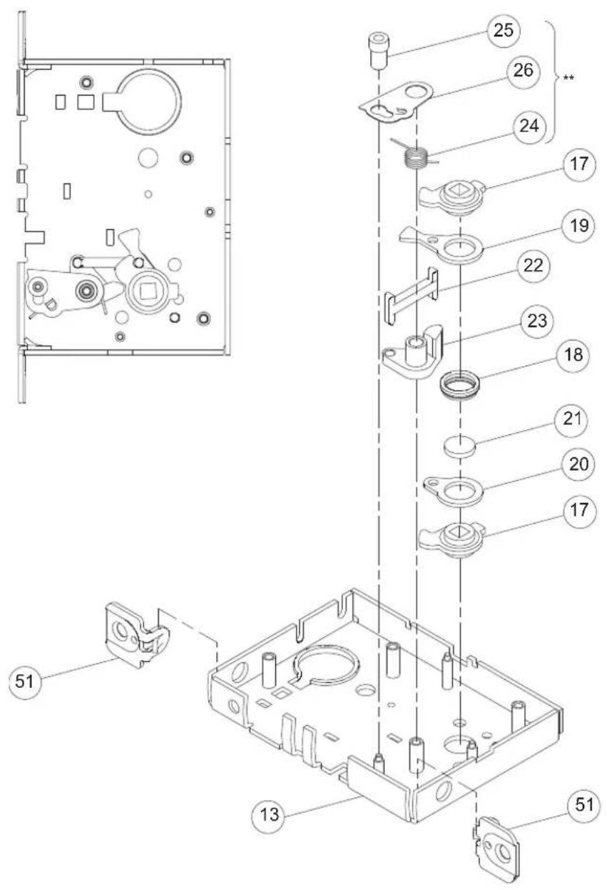
| Number | Description | Part Number |
| 13 | L9000 Lock Case L283-112 | |
| 17 | Retractor Hub L583-019 | |
| 18 | Hub Spacer L583-020 | |
| 19 | Retractor Lever L583-021 | |
| 20 | Retractor Rocker L583-022 | |
| 21 | Blocking Plate L583-023 | |
| 22 | Retractor Link L583-024 | |
| 23 | Retractor Crank L583-025 | |
| 24 | Hub Spring L583-026 | |
| 25 | Fire Door Fuse L583-027 | |
| 26 | Fire Door Catch L583-028 | |
| 51 | 1 1/4 " Faceplate Tab | L583-426 |
| 52 | Case Cover Screws L583-454 | |
| 58 | Lock Case Cover L583-496 | |

** See "Assembly of Lock Case Parts" on page 87.
NOTE: Lock case assembly shown for LH and LHR doors.
Lock Case Assemblies
L9175
Assembled Lock Case L283-144

| Number | Description | Part Number |
| 11 | Spindle Anchor Single L583-468 | |
| 13 | L9000 Lock Case L283-112 | |
| 51 | 1 1/4 " Faceplate Tab | L583-426 |
| 52 | Case Cover Screws L583-454 | |
| 58 | Lock Case Cover L583-496 |

NOTE: Lock case assembly shown for LH and LHR doors.
Lock Case Assemblies
L9176
Assembled Lock Case L283-145

| Number | Description | Part Number |
| 13 | L9000 Lock Case L283-112 | |
| 42 | Spindle Anchor L583-057 | |
| 51 | 1 1/4 " Faceplate Tab | L583-426 |
| 52 | Case Cover Screws L583-454 | |
| 58 | Lock Case Cover L583-496 |
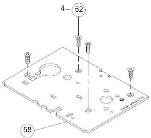
NOTE: Lock case assembly shown for LH and LHR doors.
Lock Case Assemblies
L9440, L9444
Assembled Lock Case L283-062

| Number | Description | Part Number |
| 3 | Deadbolt L283-003 | |
| 6 | Latchbolt L283-008 | |
| 13 | L9000 Lock Case L283-112 | |
| 17 | Retractor Hub L583-019 | |
| 18 | Hub Spacer L583-020 | |
| 19 | Retractor Lever L583-021 | |
| 20 | Retractor Rocker L583-022 | |
| 21 | Blocking Plate L583-023 | |
| 22 | Retractor Link L583-024 | |
| 23 | Retractor Crank L583-025 | |
| 24 | Hub Spring L583-026 | |
| 25 | Fire Door Fuse L583-027 | |
| 26 | Fire Door Catch L583-028 | |
| 27 | Turn Hub L583-029 | |
| 30 | Turn Hub Spring L583-035 | |
| 31 | Auxiliary Bar Guide L583-038 | |
| 34 | Locking Catch L583-045 | |
| 36 | Locking Link L583-048 | |
| 38 | Link Pin L583-050 | |
| 39 | Transfer Lever L583-051 | |
| 43 | Simultaneous Retractor L583-058 | |
| 51 | 1 1/4 " Faceplate Tab L583-426 | |
| 52 | Case Cover Screws L583-454 | |
| 53 | Cylinder Retainer Screw L583-481 | |
| 54 | Lock Handing Screw L583-485 | |
| 55 | Cylinder Retainer L583-490 | |
| 56 | Screw Plate L583-492 | |
| 58 | Lock Case Cover L583-496 |

** See "Assembly of Lock Case Parts" on page 87.
NOTE: Lock case assembly shown for LH and LHR doors. See page 118 for instructions on changing the lock hand.
Lock Case Assemblies
LV9440, LV9444
Assembled Lock Case L283-181

| Number | Description | Part Number |
| 3 | Deadbolt L283-003 | |
| 6 | Latchbolt L283-008 | |
| 10 | Cylinder Plate & Screw L283-055 | |
| 13 | L9000 Lock Case L283-112 | |
| 22 | Retractor Link L583-024 | |
| 24 | Hub Spring L583-026 | |
| 25 | Fire Door Fuse L583-027 | |
| 26 | Fire Door Catch L583-028 | |
| 27 | Turn Hub L583-029 | |
| 30 | Turn Hub Spring L583-035 | |
| 31 | Auxiliary Bar Guide L583-038 | |
| 36 | Locking Link L583-048 | |
| 38 | Link Pin L583-050 | |
| 39 | Transfer Lever L583-051 | |
| 43 | Simultaneous Retractor L583-058 | |
| 51 | 11/4 " Faceplate Tab L583-426 | |
| 52 | Case Cover Screws L583-454 | |
| 53 | Cylinder Retainer Screw L583-481 | |
| 54 | Lock Handing Screw L583-485 | |
| 55 | Cylinder Retainer L583-490 | |
| 56 | Screw Plate L583-492 | |
| 58 | Lock Case Cover L583-496 | |
| 60 | Retractor Lever Assy L283-147 | |
| 61 | Crank Retractor L583-383 | |
| 62 | Bottom Hub L583-386 | |
| 63 | Top Hub L583-387 | |
| 64 | Retractor Catch L583-345 |

** See "Assembly of Lock Case Parts" on page 87.
NOTE: Lock case assembly shown for RH and RHR doors. See page 118 for instructions on changing the lock hand.
Lock Case Assemblies
L9453
Assembled Lock Case L283-137

| Number | Description | Part Number |
| 4 | Entrance Deadbolt L283-004 | |
| 5 | Auxiliary Latchbolt L283-006 | |
| 6 | Latchbolt L283-008 | |
| 10 | Cylinder Plate & Screw L283-055 | |
| 13 | L9000 Lock Case L283-112 | |
| 17 | Retractor Hub L583-019 | |
| 18 | Hub Spacer L583-020 | |
| 19 | Retractor Lever L583-021 | |
| 20 | Retractor Rocker L583-022 | |
| 21 | Blocking Plate L583-023 | |
| 22 | Retractor Link L583-024 | |
| 23 | Retractor Crank L583-025 | |
| 24 | Hub Spring L583-026 | |
| 25 | Fire Door Fuse L583-027 | |
| 26 | Fire Door Catch L583-028 | |
| 28 | Entrance Hub L583-030 | |
| 29 | Cam Follower L583-031 | |
| 30 | Turn Hub Spring L583-035 | |
| 33 | Stop Spring L583-044 | |
| 34 | Locking Catch L583-045 | |
| 35 | Catch Spring L583-047 | |
| 37 | Entrance Link L583-049 | |
| 38 | Link Pin L583-050 | |
| 39 | Transfer Lever L583-051 | |
| 40 | Simultaneous Retractor L583-053 | |
| 50 | Auxiliary Stop L583-196 | |
| 51 | 1 1/4 " Faceplate Tab | L583-426 |
| 52 | Case Cover Screws L583-454 | |
| 53 | Cylinder Retainer Screw L583-481 | |
| 54 | Lock Handing Screw L583-485 | |
| 55 | Cylinder Retainer L583-490 | |
| 56 | Screw Plate L583-492 | |
| 58 | Lock Case Cover L583-496 |

** See "Assembly of Lock Case Parts" on page 87.
NOTE: Lock case assembly shown for LH and LHR doors. See page 118 for instructions on changing the lock hand.
Lock Case Assemblies
LV9453
Assembled Lock Case L283-176
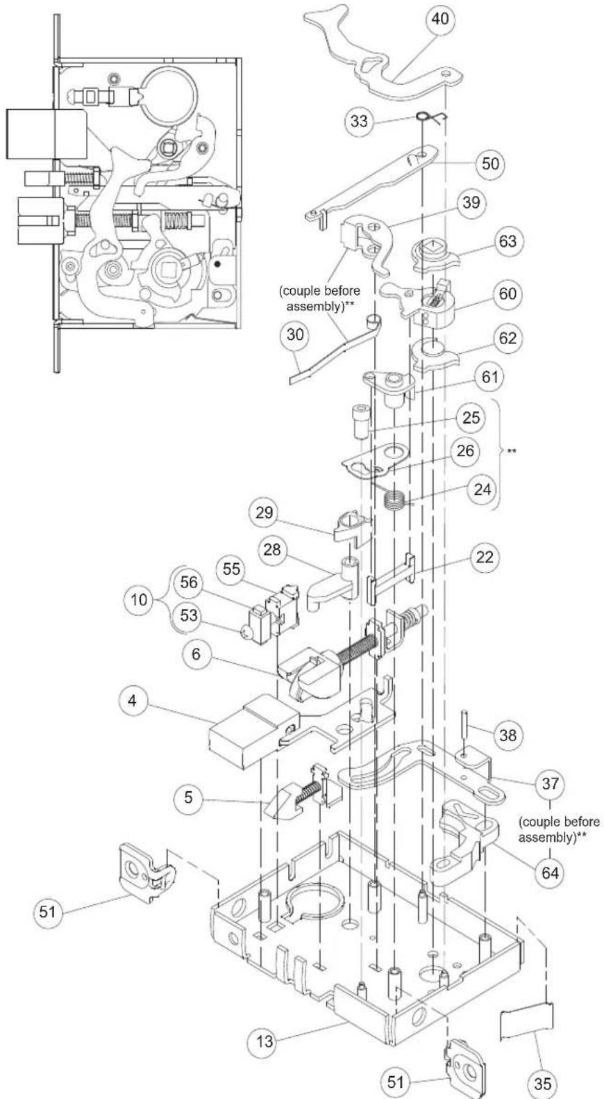
| Number | Description | Part Number |
| 4 | Entrance Deadbolt L283-004 | |
| 5 | Auxiliary Latchbolt L283-006 | |
| 6 | Latchbolt L283-008 | |
| 10 | Cylinder Plate & Screw L283-055 | |
| 13 | L9000 Lock Case L283-112 | |
| 22 | Retractor Link L583-024 | |
| 24 | Hub Spring L583-026 | |
| 25 | Fire Door Fuse L583-027 | |
| 26 | Fire Door Catch L583-028 | |
| 28 | Entrance Hub L583-030 | |
| 29 | Cam Follower L583-031 | |
| 30 | Turn Hub Spring L583-035 | |
| 33 | Stop Spring L583-044 | |
| 35 | Catch Spring L583-047 | |
| 37 | Entrance Link L583-049 | |
| 38 | Link Pin L583-050 | |
| 39 | Transfer Lever L583-051 | |
| 40 | Simultaneous Retractor L583-053 | |
| 50 | Auxiliary Stop L583-196 | |
| 51 | 11/4 " Faceplate Tab L583-426 | |
| 52 | Case Cover Screws L583-454 | |
| 53 | Cylinder Retainer Screw L583-481 | |
| 54 | Lock Handing Screw L583-485 | |
| 55 | Cylinder Retainer L583-490 | |
| 56 | Screw Plate L583-492 | |
| 58 | Lock Case Cover L583-496 | |
| 60 | Retractor Lever Assy L283-147 | |
| 61 | Crank Retractor L583-383 | |
| 62 | Bottom Hub L583-386 | |
| 63 | Top Hub L583-387 | |
| 64 | Retractor Catch L583-345 |

** See "Assembly of Lock Case Parts" on page 87.
NOTE: Lock case assembly shown for RH and RHR doors. See page 118 for instructions on changing the lock hand.
Lock Case Assemblies
L9456, L9457, L9496
Assembled Lock Case L283-138

| Number Description | Part Number |
| 3 Dead bolt L283-003 | |
| 6 Latch bolt L283-008 | |
| 10 Cylinder Plate & Screw L283-055 | |
| 13 L9000 Lock Case L283-112 | |
| 17 Retractor Hub L583-019 | |
| 18 Hub Spacer L583-020 | |
| 19 Retractor Lever L583-021 | |
| 20 Retractor Rocker L583-022 | |
| 21 Blocking Plate L583-023 | |
| 22 Retractor Link L583-024 | |
| 23 Retractor Crank L583-025 | |
| 24 Hub Spring L583-026 | |
| 25 Fire Door Fuse L583-027 | |
| 26 Fire Door Catch L583-028 | |
| 27 Turn Hub L583-029 | |
| 30 Turn Hub Spring L583-035 | |
| 31 Auxiliary Bar Guide L583-038 | |
| 34 Locking Catch L583-045 | |
| 36 Locking Link L583-048 | |
| 38 Link Pin L583-050 | |
| 39 Transfer Lever L583-051 | |
| 40 Simultaneous Retractor L583-053 | |
| 51 1 1/4 " Faceplate Tab | L583-426 |
| 52 Case Cover Screws L583-454 | |
| 53 Cylinder Retainer Screw L583-481 | |
| 54 Lock Handing Screw L583-485 | |
| 55 Cylinder Retainer L583-490 | |
| 56 Screw Plate L583-492 | |
| 58 Lock Case Cover L583-496 |

** See "Assembly of Lock Case Parts" on page 87.
NOTE: Lock case assembly shown for LH and LHR doors. See page 118 for instructions on changing the lock hand.
Lock Case Assemblies
LV9456, LV9457, LV9496
Assembled Lock Case L283-177

| Number | Description | Part Number |
| 3 | Deadbolt L283-003 | |
| 6 | Latchbolt L283-008 | |
| 10 | Cylinder Plate & Screw L283-055 | |
| 13 | L9000 Lock Case L283-112 | |
| 22 | Retractor Link L583-024 | |
| 24 | Hub Spring L583-026 | |
| 25 | Fire Door Fuse L583-027 | |
| 26 | Fire Door Catch L583-028 | |
| 27 | Turn Hub L583-029 | |
| 30 | Turn Hub Spring L583-035 | |
| 31 | Auxiliary Bar Guide L583-038 | |
| 36 | Locking Link L583-048 | |
| 38 | Link Pin L583-050 | |
| 39 | Transfer Lever L583-051 | |
| 40 | Simultaneous Retractor L583-053 | |
| 51 | 11/4" Faceplate Tab L583-426 | |
| 52 | Case Cover Screws L583-454 | |
| 53 | Cylinder Retainer Screw L583-481 | |
| 54 | Lock Handing Screw L583-485 | |
| 55 | Cylinder Retainer L583-490 | |
| 56 | Screw Plate L583-492 | |
| 58 | Lock Case Cover L583-496 | |
| 60 | Retractor Lever Assy L583-147 | |
| 61 | Crank Retractor L583-383 | |
| 62 | Bottom Hub L583-386 | |
| 63 | Top Hub L583-387 | |
| 64 | Retractor Catch L583-345 |

** See "Assembly of Lock Case Parts" on page 87.
NOTE: Lock case assembly shown for RH and RHR doors. See page 118 for instructions on changing the lock hand.
Lock Case Assemblies
L9460, L9462, L9463, L9464
Assembled Lock Case L283-139
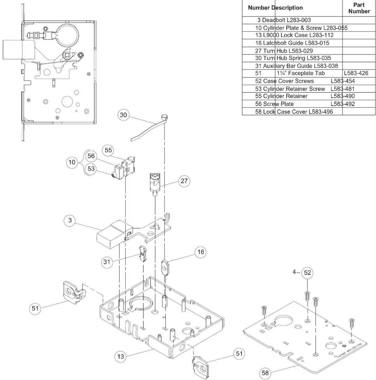
NOTE: Lock case assembly shown for LH and LHR doors.
Lock Case Assemblies
L9460 x XL11-635
Assembled Lock Case XL11-661

| Number | Description | Part Number |
| 3 | Deadbolt L283-003 | |
| 10 | Cylinder Plate & Screw L283-055 | |
| 13 | L9000 Lock Case L283-112 | |
| 16 | Latchbolt Guide L583-015 | |
| 27 | Turn Hub L583-029 | |
| 30 | Turn Hub Spring L583-035 | |
| 31 | Auxiliary Bar Guide L583-038 | |
| 42 | Spindle Anchor L583-057 | |
| 51 | 1 1/4 " Faceplate Tab | L583-426 |
| 52 | Case Cover Screws | L583-454 |
| 53 | Cylinder Retainer Screw | L583-481 |
| 55 | Cylinder Retainer | L583-490 |
| 56 | Screw Plate | L583-492 |
| 58 | Lock Case Cover L583-496 |


NOTE: Lock case assembly shown for LH and LHR doors.
Lock Case Assemblies
L9460 x XL11-886, L9462 x XL11-886, L9464 x XL11-886
Assembled Lock Case XL11-886

** See "Assembly of Lock Case Parts" on page 87.
NOTE: Lock case assembly shown for LH and LHR doors. See page 118 for instructions on changing the lock hand.
Lock Case Assemblies
L9465, L9466, L9473
Assembled Lock Case L283-140

| Number | Description | Part Number |
| 6 | Latchbolt L283-008 | |
| 10 | Cylinder Plate & Screw L283-055 | |
| 12 | Deadbolt L583-075 | |
| 13 | L9000 Lock Case L283-112 | |
| 17 | Retractor Hub L583-019 | |
| 18 | Hub Spacer L583-020 | |
| 19 | Retractor Lever L583-021 | |
| 20 | Retractor Rocker L583-022 | |
| 21 | Blocking Plate L583-023 | |
| 22 | Retractor Link L583-024 | |
| 23 | Retractor Crank L583-025 | |
| 24 | Hub Spring L583-026 | |
| 25 | Fire Door Fuse L583-027 | |
| 26 | Fire Door Catch L583-028 | |
| 27 | Turn Hub L583-029 | |
| 30 | Turn Hub Spring L583-035 | |
| 31 | Auxiliary Bar Guide L583-038 | |
| 51 | 11/4 " Faceplate Tab | L583-426 |
| 52 | Case Cover Screws L583-454 | |
| 53 | Cylinder Retainer Screw L583-481 | |
| 55 | Cylinder Retainer L583-490 | |
| 56 | Screw Plate L583-492 | |
| 58 | Lock Case Cover L583-496 |
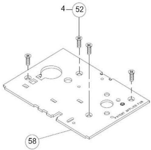
** See "Assembly of Lock Case Parts" on page 87.
NOTE: Lock case assembly shown for LH and LHR doors.
Lock Case Assemblies
L9480, L9485, L9486, L9486 x L583-375
Assembled Lock Case L283-141

| Number | Description | Part Number |
| 3 | Deadbolt L283-003 | |
| 5 | Auxiliary Latchbolt L283-006 | |
| 6 | Latchbolt L283-008 | |
| 10 | Cylinder Plate & Screw L283-055 | |
| 13 | L9000 Lock Case L283-112 | |
| 17 | Retractor Hub L583-019 | |
| 18 | Hub Spacer L583-020 | |
| 19 | Retractor Lever L583-021 | |
| 20 | Retractor Rocker L583-022 | |
| 21 | Blocking Plate L583-023 | |
| 22 | Retractor Link L583-024 | |
| 23 | Retractor Crank L583-025 | |
| 24 | Hub Spring L583-026 | |
| 25 | Fire Door Fuse L583-027 | |
| 26 | Fire Door Catch L583-028 | |
| 27 | Turn Hub L583-029 | |
| 30 | Turn Hub Spring L583-035 | |
| 33 | Stop Spring L583-044 | |
| 34 | Locking Catch L583-045 | |
| 39 | Transfer Lever L583-051 | |
| 40 | Simultaneous Retractor L583-053 | |
| 41 | Catch Pin L583-056 | |
| 50 | Auxiliary Stop L583-196 | |
| 51 | 11/4 " Faceplate Tab L583-426 | |
| 52 | Case Cover Screws L583-454 | |
| 53 | Cylinder Retainer Screw L583-481 | |
| 54 | Lock Handing Screw L583-485 | |
| 55 | Cylinder Retainer L583-490 | |
| 56 | Screw Plate L583-492 | |
| 58 | Lock Case Cover L583-496 |

** See "Assembly of Lock Case Parts" on page 87.
NOTE: Lock case assembly shown for LH and LHR doors. See page 118 for instructions on changing the lock hand.
Lock Case Assemblies
LV9480, LV9485, LV9486, LV9486 x L583-375
Assembled Lock Case L283-178

| Number | Description | Part Number |
| 3 | Deadbolt L283-003 | |
| 5 | Auxiliary Latchbolt L283-006 | |
| 6 | Latchbolt L283-008 | |
| 10 | Cylinder Plate & Screw L283-055 | |
| 13 | L9000 Lock Case L283-112 | |
| 22 | Retractor Link L583-024 | |
| 24 | Hub Spring L583-026 | |
| 25 | Fire Door Fuse L583-027 | |
| 26 | Fire Door Catch L583-028 | |
| 27 | Turn Hub L583-029 | |
| 30 | Turn Hub Spring L583-035 | |
| 33 | Stop Spring L583-044 | |
| 39 | Transfer Lever L583-051 | |
| 40 | Simultaneous Retractor L583-053 | |
| 41 | Catch Pin L583-056 | |
| 50 | Auxiliary Stop L583-196 | |
| 51 | 11/4 " Faceplate Tab L583-426 | |
| 52 | Case Cover Screws L583-454 | |
| 53 | Cylinder Retainer Screw L583-481 | |
| 54 | Lock Handing Screw L583-485 | |
| 55 | Cylinder Retainer L583-490 | |
| 56 | Screw Plate L583-492 | |
| 58 | Lock Case Cover L583-496 | |
| 60 | Retractor Lever Assy L283-147 | |
| 61 | Crank Retractor L583-383 | |
| 62 | Bottom Hub L583-386 | |
| 63 | Top Hub L583-387 | |
| 64 | Retractor Catch L583-345 |

** See "Assembly of Lock Case Parts" on page 87.
NOTE: Lock case assembly shown for RH and RHR doors. See page 118 for instructions on changing the lock hand.
Lock Case Assemblies
L9482 x XL11-543
Assembled Lock Case L283-146 x XL11-543

| Number | Description | Part Number |
| 3 | Deadbolt L283-003 | |
| 5 | Auxiliary Latchbolt L283-006 | |
| 6 | Latchbolt L283-008 | |
| 10 | Cylinder Plate & Screw L283-055 | |
| 13 | L9000 Lock Case L283-112 | |
| 27 | Turn Hub L583-029 | |
| 30 | Turn Hub Spring L583-035 | |
| 33 | Stop Spring L583-044 | |
| 39 | Transfer Lever L583-051 | |
| 42 | Spindle Anchor L583-057 | |
| 50 | Auxiliary Stop L583-196 | |
| 51 | 1 1/4 " Faceplate Tab L583-426 | |
| 52 | Case Cover Screws L583-454 | |
| 53 | Cylinder Retainer Screw L583-481 | |
| 55 | Cylinder Retainer L583-490 | |
| 56 | Screw Plate L583-492 | |
| 58 | Lock Case Cover L583-496 |

** See "Assembly of Lock Case Parts" on page 87.
NOTE: Lock case assembly shown for LH and LHR doors.
Lock Case Assemblies
LV9482 x XL11-543
Assembled Lock Case L283-183

| Number | Description | Part Number |
| 3 | Deadbolt L283-003 | |
| 5 | Auxiliary Latchbolt L283-006 | |
| 6 | Latchbolt L283-008 | |
| 10 | Cylinder Plate & Screw L283-055 | |
| 13 | L9000 Lock Case L283-112 | |
| 27 | Turn Hub L583-029 | |
| 30 | Turn Hub Spring L583-035 | |
| 33 | Stop Spring L583-044 | |
| 39 | Transfer Lever L583-051 | |
| 50 | Auxiliary Stop L583-196 | |
| 51 | 11/4" Faceplate Tab | L583-426 |
| 52 | Case Cover Screws L583-454 | |
| 53 | Cylinder Retainer Screw L583-481 | |
| 55 | Cylinder Retainer L583-490 | |
| 56 | Screw Plate L583-492 | |
| 58 | Lock Case Cover L583-496 | |
| 62 | Bottom Hub L583-386 | |
| 63 | Top Hub L583-387 | |
| 65 | Spacer L583-346 |

** See "Assembly of Lock Case Parts" on page 87. NOTE: Lock case assembly shown for RH and RHR doors.
Lock Case Assemblies
L9485 x XL11-557
Assembled Lock Case XL11-557

** See "Assembly of Lock Case Parts" on page 87.
NOTE: Lock case assembly shown for LH and LHR doors. See page 118 for instructions on changing the lock hand.
Lock Case Assembly Compatibility
| Lock Case (7-15-94) | L283-130 | Lock Case (4-1-94) | Lock Case Cover | L583-484 | Faceplate Tab | L583-426 | Lock Handing Screw | L583-485 | Cylinder Retainer Assembly | L583-480/481/482 | Lock Case | L283-080 | Lock Case Cover | L583-452 | Faceplate Tab | L583-006 | Faceplate Tab Screw | L583-046 | Lock Handing Screw | L583-046 | Cylinder Anchor Assembly | L283-005 |
| • | • | L283-005Cylinder Anchor Assembly | ||||||||||||||||||||
| • | • | L583-046Lock Handing Screw | ||||||||||||||||||||
| • | • | • | L583-046Faceplate Tab Screw | |||||||||||||||||||
| • | • | • | L583-006, L583-007Faceplate Tab | |||||||||||||||||||
| • | • | • | • | L583-452Lock Case Cover | ||||||||||||||||||
| • | • | • | • | • | • | • | • | • | • | L283-080Lock Case | ||||||||||||
| • | • | • | • | L583-480/481/482Cylinder Retainer Assembly | ||||||||||||||||||
| • | • | L583-485Lock Handing Screw | ||||||||||||||||||||
| • | • | L583-426, L583-427Faceplate Tab | ||||||||||||||||||||
| • | • | • | • | • | L583-484Lock Case Cover | |||||||||||||||||
| • | • | • | • | • | • | • | L283-130Lock Case (April 1, 1994) | |||||||||||||||
| • | • | • | • | L283-130Lock Case (July 15, 1994) |
Use this table to determine compatibility between parts for lock manufactured in 1994.
Assembly of Lock Case Parts
Turn Hub Spring and Transfer Lever

Locking Catch / Retractor Catch and Locking Link

Assembly of Lock Case Parts
L FUNCTIONS ONLY Fire Door Fuse, Fire Door Catch and Hub Spring

LV FUNCTIONS ONLY Fire Door Fuse, Fire Door Catch and Hub Spring


Trim Options
Cast or Forged Lever Designs
Levers are available in forged brass or bronze, and cast stainless steel. Levers are shown with rose trim A or B. Also available with L or N escutcheon. See escutcheon options on page 92-94.

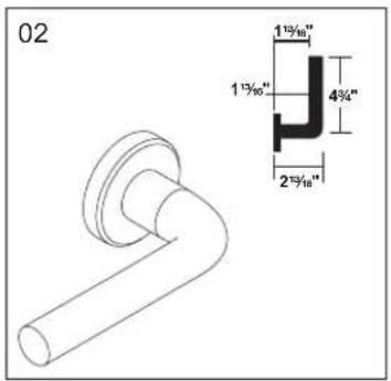


Inside Lever Assembly Outside Lever Assembly


NOTE: See Schlage Commercial Price Book for available finishes.
Trim Options
Wrought Knob Designs
Knobs shown with rose trim A or B. Also available with L or N escutcheons. See escutcheon options on page 92-94.


Inside Knob Assembly Outside Knob Assembly


Rose Trim A or B Inside Rose Blank Outside Rose
09-503 09-508
Rose Design A- 21/8 dia. x 13/32
Rose Design B- 29/16 " dia. x 13/32 "

Furnished with mounting plate and screws. For decorative trim, see page 95.
Rose Design A- 21/8 " dia. x 13/32 " Rose Design B- 29/16 " dia. x 13/32 "

Furnished with mounting plate, screws, and plug. Used to mount inside rose trim on doors prepared for trim both sides.
Outside Rose Dimensions
09-404 (bushing attached at factory) or 09-506 with knob or lever.


L Escutcheon Trim
Outside Escutcheon Dimensions
Knob/Lever Design
(8" x 1 3/4 " x 7/16 " Cold forged brass, bronze, or stainless steel base material – Bushing attached at factory)
41, 42 01, 02, 03, 05, 06, 07, 12, 17, 18 A

CC, AST, MER, OME, STA


Outside Escutcheons
09-636 Outside Blank x Knob/Lever

Specify 09-636 or 09-550 with knob/lever.
09-637 Emergency Turn x Knob/Lever

Specify 09-637 or 09-551 with knob/lever.
09-638 Concealed Cylinder x Knob/Lever

Specify 09-638 or 09-552 with knob/lever.
09-639 Full Face Cylinder x Knob/Lever

Specify 09-639 or 09-553 with knob/lever.
09-640 Concealed Cylinder with Indicator x Knob/Lever

Specify 09-636 or 09-550 with knob/lever. Specify L583-375 for "Occupied".
09-641 Full Face Cylinder with Indicator x Knob/Lever

Specify 09-636 or 09-550 with knob/lever. Specify L583-375 for "Occupied".
XL11-636 Blank Outside 09-639

Specify XL11-636 OOL. For L9040 x XL11-446

function. Not sold separately.
NOTES: When ordering trim parts, specify the complete design and fi nish (e.g. 09-402 01A 605). See Schlage Commercial Price Book for available fi nishes.
L Escutcheon Trim
Inside Escutcheons
09-632 Blank x Knob/Lever 09-633 Thumbturn x Knob/Lever 09-634 Thumbturn x Blank


Specify door thickness: 1 3/8 " or 1 3/4 " Available with EZ Turn (ADA). (See "Trim Options" on page 97.)
Specify door thickness: 1 3/8 " or 1 3/4 " Available with EZ Turn (ADA). (See "Trim Options" on page 97.)


NOTES: When ordering trim parts, specify the complete design and fi nish (e.g. 09-632 01L 605). See Schlage Commercial Price Book for available fi nishes.
N Escutcheon Trim
Outside Escutcheon Dimensions
Knob/Lever Design
(8" x 2 9/16 " x 7/16" Heavy wrought reinforced brass, bronze, or stainless steel base material – Bushing attached at factory)


Outside Escutcheons

Specify 09-636 or 09-550 with knob/lever.

Specify 09-637 or 09-551 with knob/lever.

Specify 09-639 or 09-553 with knob/lever.

Specify XL11-636 00N and fi nish.
Inside Escutcheons
(Includes two (2) screws and mounting plate)


NOTES: When ordering trim parts, specify the complete design and fi nish (e.g. 09-402 03N 605). See Schlage Commercial Price Book for available fi nishes.
Decorative Trim
Decorative Levers

Decorative Roses

2½" diameter

2 9/16 " diameter

2 5/8 " diameter

2 5/8 " diameter
Inside Lever Assembly
(Bushing attached at factory)

Outside Lever Assembly

Furnished with spanner wrench. Furnished with retainer seating tool.
NOTE: See Schlage Commercial Price Book for available finishes.
danmark Stainless Steel Levers
630 Satin Stainless Steel Finish

2½" diameter
Trim Options
Coin Turn Coin Turn and Plug

Coin turn for rose trim.
Specify fi nish and door
thickness. Available with Torx
screws, specify L283-065.
Specify dimension, fi nish and door hand. If handing is not required, specify NH (non-handed).
"Do Not Disturb" Indicator

"Occupied" Indicator

Thumbturn ADA Cylinder Turn Cylinder Turn

Thumbturn for deadbolt functions and privacy locks with rose trim. Specify fi nish and door thickness.
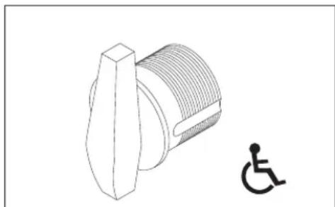
Available with L463 and L9463 locks. Specify per XB11-720, dimension, fi nish and door hand. If handing is not required, specify NH (non-handed). When ordered alone, specify either 09-900, 09-904, 09-905 or 09-907 per XB11-720.

09-900 through 09-907 Cylinder Classroom turns are furnished with L463 and L9463 locks. Specify dimension, fi nish and door hand. If handing is not required, specify NH (non-handed). For handing instructions, see page 118.
"EZ" Thumbturn (ADA) for Rose Trim

Not available for L463 or L9463 functions.
"EZ" Thumbturn (ADA) x Knob/Lever with L or N Escutcheon

Not available for L9463 functions.
"EZ" Thumbturn (ADA) x Blank with L Escutcheon

Not available for L9463 functions.
* EZ Turn is not available on doors less than 1 5/8 " thick.
NOTE: When ordering trim parts, specify the complete design and finish (e.g. 09-633-03L 605).
Trim Options
Emergency Turn
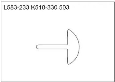
Furnished with L9040 and L9440. Furnished with L9040 and L9440. Specify fi nish.
Emergency Button

Modifi ed Inside and Outside 03 Lever for Folger Adam Co.® Lever Trak™

09-401, 09-402, or 09-506 per 503 Available for rose trim only. Lever Trak is not included.
Tactile Warning (Knurling)
Applied to outside knob/lever only unless otherwise specified. Not available on stainless steel levers.

Milling pattern for backside of 01, 06, 07, 17, and 18 levers.

Knurling pattern for 02 lever.

Knurling pattern for 03 lever.

Milling pattern for backside of 05 lever. Milling pattern for underside of 12 lever. Specify door hand.


Knurling pattern for 42 knob. Tactile warning is available for 41 and 42 knobs except for 629 and 630 fi nish.
NOTE: To specify knurling, place the number 8 in front of the lever design code (e.g. 801 for lever design 01 with knurling).
Trim Assembly Parts
Escutcheon Thru-Bolt/Screws
Two required per lock
| Part Number | Specify Finish Description Door Thickness | |
| L583-119 • L Escutcheon Thru-Bolts | Screws | 13/8" |
| L583-120 • | 13/4" | |
| L583-121 • 2" | ||
| L583-122 • | 21/4" | |
| L583-123 • | 21/2" | |
| K510-389 • N Escutcheon Thru-Bolts | Screws | 13/4" |
| K510-390 • | 2-21/4" | |
| L583-287 • L Escutcheon Thru-Bolts | Screws, L0170 Single | – |
| L583-133 • N Escutcheon Thru-Bolts | Screws, L0170 Single | – |
Standard Screw Packs
| Part Number | Specify Finish Description Contents | ||
| C203-736 455 Lock Case Mounting | Screws (2) C603-256, #12-24 WMS PFH | ||
| C203-736 • Strike Screws | (2) C603-256, #12-24 WMS PFH | ||
| K110-020 • Armor Mounting Screws | (2) K510-210, #8-32 x 1/4 " PFHMS | ||
| K110-947 • Rose Trim Thumbturn Screws | (2) K510-445, #4 x 1/2 " POH AB | ||
| L283-100 | Trim Mounting Screws and Posts, 13/4 " Doors | (2) L583-066, #8-32 x 5/8 " PFH(2) L583-212, 13/4 " Ferrule | |
| L283-101 • | L Escutcheon Thru-Bolts, 13/4 " Doors | (2) L583-120 | |
Tamper Resistant Torx Screw Packs
| Part Number | Specify Finish Description Contents | ||
| L283-121 | • Rose Trim without Thumbturn | (2) Armor screws, L583-370, #8-32 x 1/4" (T-15)(2) Strike screws, L583-371, #12-24 x 1/2" (T-20) | |
| L283-123 | • | L Escutcheon Trim for 13⁄4" Doors | (2) Armor screws, L583-370, #8-32 x 1/4" (T-15)(2) Strike screws, L583-371, #12-24 x 1/2" (T-20)(2) Esc. mtg. screws, L583-373, 1/4-28 x 21/8" (T-30) |
| L283-122 | • Rose Trim with Thumbturn | (2) Armor screws, L583-370, #8-32 x 1/4" (T-15)(2) Strike screws, L583-371, #12-24 x 1/2" (T-20)(2) Thumbturn screws, L583-372, #4 x 21/2" (T-8) | |
| XL11-848 | • | N Escutcheon Trim for 13⁄4" Doors | (2) Armor screws, L583-370, #8-32 x 1/4" (T-15)(2) Strike screws, L583-371, #12-24 x 1/2" (T-20)(2) Esc. mtg. screws, L583-373, 1/4 -28 x 21/8" (T-30) |
NOTE: Torx screw packs are furnished with appropriate T-xx installation tools.
Drivers to Operate Occupancy Indicator
(L496, L/LV9486 and L/LV9496 functions)

Trim Assembly Parts
Mounting Posts Spindles and Springs
Two required per lock Two required per lock
| L Functions LV Functions Part Number Description | |||
| Part Number Door Thickness Part Number Door Thickness | |||
| L583-211 | 13/8" | N/A | 13/8" |
| L583-212 | 13/4" | L583-497 | 13/4" |
| L583-213 | 2" | L583-498 | 2" |
| L583-215 | 21/2" | L583-500 | 21/2" |
| L583-216 | 23/4" | L583-501 | 23/4" |
| L583-217 | 3" | L583-502 | 3" |
| L583-218 | 31/4" | L583-503 | 31/4" |
| L583-219 | 31/2" | L583-504 | 31/2" |
| L283-060 | 13/8 ′′– 17/8 ′′ doors |
| L283-061 | 2 ′′– 31/2 ′′ doors |
| L283-064* | L0172 double dummyL9082 EL/EU |
| L283-065* | L0170 single dummy |
Mounting Plate for Trim One Side Only
DOOR DETAIL
For location of cylinder and/or thumbturn holes, as well as all other dimensions, see appropriate lock function template.

SCHLAGE®
Installation Instructions
L-Series
Mounting plate for trim one side

©2001 Schlage Lock Company
Printed in U.S.A.
P513-301 Rev. 01/01
IR Security & Safety
L283-150 Mounting Plate and Posts for rose trim on one side of door. For lever use with Spring Cage L283-031, for knob use with Mounting Plate L583-321.
ANSI A115.1 1990 Hollow Steel Door Installations
L283-029 For 1 3/4 " thick hollow steel doors prepared per ANSI A115.1 1990.
Install two spacers between the spring cage (or knob mounting plate) and lock chassis as shown. Spacers are required for both the inside and outside escutcheons.
NOTE: L-design escutcheons are not applicable for ANSI A115.1 door preparations.
Spring cage (lever applications) OR
Mounting plate (knob applications)

Armor Fronts
| 11⁄4" Square Corner | 11⁄16" Square Corner* | Function and Description | 11⁄4" Square Corner | 11⁄16" Square Corner* | Function and Description |
09-661 09-667 09-665 09-671 |  | Blank DeadboltL9110L9175L9176 |  |  | L9460L9462L9463L9464 |
09-662 09-668 09-666 09-672 |  | Latch Latch x Aux Latch x DeadboltUL ULL9010L9040LV9040L9044LV9044 |  |  | L9453 LV9482LV9453 L9485L9480 LV9485LV9480 L9486L9482 LV9486 |
09-663 09-669 09-713 — |  | Latch x Auxiliary Latch Latch xAuxiliary Latch (holdback)UL L9076L9050 LV9070LV9050 L9071L9056 LV9071LV9056 L9080L9060 L9082LV9060 LV9082L9070 |  | LV9076L9077LV9077 | |
09-664 09-670 09-717 — |  | Latch x Deadbolt DeadboltUL L460L9440 LV9457LV9440 L9465L9444 L9466LV9444 L9473L9456 L9496LV9456 LV9496L9457 |  | L462L463L464L480L496 |
For use with 1 3/8 " thick doors. Use with 1 1/16 " Faceplate Tab, L583-427.
Strikes
Square Corner 10-072 Square

Corner 10-072 Square Corner

10-073 Square Corner 10-075


Square Corner 10-078 Square

Corner 10-079 Square Corner

10-091 Square Corner 10-091


Square Corner XL11-820 Squa

re Corner XL11-821 Strike Re

nforcer 37-015 Strike Box K510-066


Strike Dimensions and Components
| Part Number Lip Lock Series Door | Range Box Screw 2 ea. | ||||
| 10-072* | 1" | L9010 to L9496 | 2" K510-066 | C603-256 | |
| 13/16" 13/8" - 17/8" | K510-066 C603-256 | ||||
| 11/2" | 17/8" - 21/8" | K510-066 C603-256 | |||
| 13/4" | 21/8" - 25/8" | K510-066 C603-256 | |||
| 2" | 25/8" - 31/8" | K510-066 C603-256 | |||
| 7/8" | — K510-066 | C603-256 | |||
| 10-073 | — | — K510-066 | C603-256 | ||
| 10-075*** | — | L9000 Series | — | — | C603-256 |
| 10-078 | — | L400 Series | — K510-066 | C603-256 | |
| 10-079 | — | — K510-053 | C603-256 | ||
| 10-091** | 13/16" | L9175, L9176 | 13/8" - 17/8" | — | K510-210 |
| XL11-820**, XL11-821** | 13/16" | L9000 Non-Deadbolt Functions | 13/8" - 17/8" | K510-066 C603-256 | |
| 37-015 | — | L9000 | — | — | — |
Cylinder Specifications
How to Measure Cylinder Lengths

Full Face and Interchangeable Core Concealed

Cylinder Length Dimension Chart
| Cylinder Length Dimension | |
| 11/8" | 118 |
| 11/4" | 114 |
| 13/8" | 138 |
| 11/2" | 112 |
| 15/8" | 158 |
| 13/4" | 134 |
L-Series and LV-Series Cylinder and Length Requirements
| Function Trim Cylinder | Door Thickness | |||||
| 13/8 " | 13/4 " | 2" | 21/4 " | |||
| Dimension | ||||||
| L9050, L9056, L9070, L9076, L9080, L9453, L9456, L9460 per XL11-635/886, L9464 per XL11-886, L9465, L9473, L9480 | Rose 30-001 118 1 | 18 118 118 | ||||
| Escutcheon 30-021 | 118 114 138 | 112 | ||||
| Concealed 30-004 | 118 114 138 | 112 | ||||
| L9485 | Rose 30-002 — 118 | 118 118 | ||||
| Escutcheon 30-022 | — 114 138 | 112 | ||||
| Concealed 30-005 | — 114 138 | 112 | ||||
| L9486 | Rose 30-002 114 1 | 38 112 158 | ||||
| Escutcheon 30-022 | 118 114 138 | 112 | ||||
| Concealed 30-005 | 118 114 138 | 112 | ||||
| L9496 | Rose 30-001 114 1 | 38 112 158 | ||||
| Escutcheon 30-021 | 118 114 138 | 112 | ||||
| Concealed 30-004 | 118 114 138 | 112 | ||||
| L9060 Inside, L9071, L9077, L9082, L9082EL/EU, L9457, L9462 per XL11-886, L9464, L9466, L9482 | Rose 30-001 118 1 | 18 118 118 | ||||
| Escutcheon | 30-001 114 — — — | |||||
| 30-021 — | 118 114 138 | |||||
| Concealed 30-004 | — 118 114 118 | |||||
| L9060 Outside | Rose 20-001 118 1 | 18 118 118 | ||||
| Escutcheon | 20-001 114 — — — | |||||
| 26-021 — | 118 114 138 | |||||
| Concealed 26-023 | — 118 114 138 | |||||
| L460, L462, L463, L464, L496, L9460, L9462, L9463, L9464 | Rose Trim Only | 30-001 118 | 118 118 118 | |||
NOTE: Blocking ring and/or compression rings may be required and must be ordered separately.
Full Face Cylinders
Exploded View—Everest® Modular Mortise Cylinder

Exploded View—Classic Mortise Cylinder

Exploded View—Hotel Mortise Cylinder

Full Face Cylinders


Front Cylinder Only Cylinder with Compression Ring & Spring
L-Series and LV-Series (except L9060/LV9060 Outside)
| Description Cylinder Mechanism Complete Cylinder Cams | |||
| Cylinder Only:L & N Escutcheons | Conventional 30-021 | Traditional Cams | |
| Primus®Controlled Access 20-793 L583-254 | L583-153Classic Conventional Everest® and Primus®  | ||
| Primus®XP Controlled Access 20-793-XP | |||
| Primus®UL437 20-593 | |||
| Primus®XP UL437 20-593-XP | |||
| Hotel Function 30-022* | |||
| Cylinder with CompressionRing & Spring:Rose Trim | Conventional | 30-001 | |
| Primus®Controlled Access 20-787 | |||
| Primus®XP Controlled Access 20-787-XP | Modular Cams | ||
| Primus®UL437 20-587 L583-474 | L583-475 | ||
| Primus®XP UL437 20-587-XP | |||
| Primus®Lockout | 20-717 | ||
| Primus®XP Lockout 20-717-XP | |||
| Primus®UL437 Lockout | 20-517 | ||
| Primus®XP UL437 Lockout | 20-517-XP | ||
| Hotel Function 30-002* | |||
L-Series and LV-Series L9060/LV9060 Outside
| Description | Cylinder Mechanism | Complete Cylinder | Cams | |
| Cylinder Only:L & N Escutcheons | Conventional 26-021 | Traditional Cams | ||
| Primus®Controlled Access 20-701 | B502-191 Conventional | B502-948 Everest®and Primus® | ||
| Primus®XP Controlled Access 20-701-XP | ||||
| Primus®UL437 20-501 |  |  | ||
| Primus®XP UL437 20-501-XP | ||||
| Cylinder with Compression Ring & Spring:Rose Trim | Conventional | 20-001 | ||
| Primus®Controlled Access 20-700 | ||||
| Primus®XP Controlled Access 20-700-XP | ||||
| Primus®UL437 20-500 | Modular Cams | |||
| Primus®XP UL437 20-500-XP | L583-476 | L583-477 | ||
| Primus®Lockout | 20-715 | |||
| Primus®XP Lockout 20-715-XP |  |  | ||
| Primus®UL437 Lockout | 20-515 | |||
| Primus®XP UL437 Lockout | 20-515-XP | |||
| Cylinder with Compression Ring & 1⁄8” Blocking Ring | Conventional 20-002 | |||
* Specify hand for hotel function cylinders. Not available in Primus®. Furnished 0-bitted; emergency keys must be ordered separately. NOTES: Lockout keys are not furnished with cylinders and must be ordered separately. Lockout cylinders will not be master keyed by Schlage.
Concealed Cylinders
Exploded View—Everest® Mortise Cylinder

Exploded View—Classic Mortise Cylinder

Exploded View—Hotel Mortise Cylinder

Concealed Cylinders

L-Series and LV-Series (except L9060/LV9060 Outside)
| Description Cylinder | Mechanism Complete Cylinder Cam | ||
| Cylinder Only:L Escutcheon | Conventional 30-004 | L583-254 Conventional  L583-153 Everest® and Primus® L583-153 Everest® and Primus® | |
| Primus® Controlled Access 20-789 | |||
| Primus® XP Controlled Access 20-789-XP | |||
| Primus® UL437 20-589 | |||
| Primus® XP UL437 20-589-XP | |||
| Hotel Function 30-005* | |||
L-Series and LV-Series L9060/LV9060 Outside
| Description Cylinder | Mechanism Complete Cylinder Cam | |||
| Cylinder Only:L Escutcheon | Conventional 26-023 | B502-191 Conventional | B502-948 Everest® and Primus® | |
| Primus® Controlled Access | 24-767 | |||
| Primus® XP Controlled Access | 24-767-XP |  |  | |
| Primus® UL437 | 24-567 | |||
| Primus® XP UL437 | 24-567-XP | — | — | |
* Specify hand for hotel function cylinders. Not available in Primus®. Emergency keys must be ordered separately.
NOTES: 1) Everest® hotel function cylinders are available in 1 1/8 , 1 1/4 , and 1 3/8 only.
2) 1 1/8 " (Dim=118) cylinders are furnished unless otherwise specified. Cylinder length depends on function, trim and door thickness.
3) Finishes: 606 and 626.
4) Specify LKB if 0-bitted Primus cylinders are required less key blanks.
5) Extended lengths are available.
Full Size Interchangeable Cores
Exploded View–Full Size Classic

Exploded View–Full Size Hotel Classic

Full Size Interchangeable Cores

L-Series and LV-Series (except L9060/LV9060 Outside)
| Description Cylinder Mechanism Complete Cylinder Cam | |||
| Cylinder Only:L & N Escutcheons | Housing Less Core 30-016 |  | |
| Cylinder with Compression Ring& Spring: L & N Escutcheons | Conventional Core 30-008* L583-489 | ||
| Primus®Core 20-798 | |||
| Primus®XP Core 20-798-XP | |||
| Hotel Function 30-010** | |||
| Housing Less Core 30-007 | |||
| Cylinder with CompressionRing, Compression Spring and 3/8" Blocking Ring: Rose Trim | Conventional Core 30-138* | ||
| Primus®Core 20-776 | |||
| Primus®XP Core 20-776-XP | |||
| Hotel Function Core 30-140** | |||
| Housing Less Core 30-137 | |||
L-Series and LV-Series L9060/LV9060 Outside
| Description Cylinder Mechanism Complete Cylinder Cam | |||
| Cylinder Only:L & N Escutcheons | Housing Less Core 30-032 | K510-680 | |
| Cylinder with Compression Ring & Spring:L & N Escutcheons | Conventional Core | 30-030* | |
| Primus®Core | 20-782 | ||
| Primus®XP Core 20-782-XP | |||
| Cylinder with Compression Ring, Compression Spring and 1⁄2" Blocking Ring: Rose Trim*** | Primus®Core | 20-783 | |
| Primus®XP Core 20-783-XP | |||
* Can be ordered with construction core.
** Specify hand for hotel function cylinders. Not available in Primus®. Emergency key must be ordered separately.
*** For this configuration with conventional core, order 30-030 cylinder and 36-082-050 blocking ring.
Full Size Interchangeable Cores


Full Size Cores
| Part Number Description | |
| 23-030 Conventional Core | |
| 23-031 Conventional Core less logo | |
| 20-740 Primus | ® Core |
| 20-740-XP Primus | ® XP Core |
| 20-741 Primus | ® Core less logo |
| 20-741-XP Primus | ® XP Core less logo |
| 30-120* Hotel Function Conventional Core for L9485 and L9486 | |
| 30-121* Hotel Function Conventional Core, less logo, for L9485 and L9486 | |
Full Size Core Parts
| Part Number Description | |
| C503-115 Cap Pin | Spring (Order in multiples of 100) |
| C503-118 Retainer | Cap (Order in multiples of 25) |
| C603-347** Cap Pin | (Order in multiples of 100) |
| C603-827 Cap Pin | (Order in multiples of 100) |
| C603-956 Actuating Ring | |
| C603-964 Actuating Pin | (Control top pin) |
| C603-967 Control Bottom Pin | (Order in multiples of 100) |
* Specify hand for hotel function cores. Emergency keys must be ordered separately.
** For cores manufactured before November 1997.
NOTES: 1) Control keys must be ordered separately.
2) Finishes: 606 and 626.
3) Full size cores, conventional and Primus ® , can be integrated into any Schlage key system with compatible Everest ® or
Classic keyways.
4) ® Boirensusan be integrated into any Schlage 6-pin key system with compatible Primus keyways.
5) ® Boires are Controlled Access. Specify LKB if 0-bitted Primus cores are required less key blanks.
Small Format Interchangeable Core
Exploded View – Small Format Everest® Keyways

Everest® Patented Keyway Cores
| Part Number Description | 80-036/80-037 | |
| 80-037 Everest | ® Combinated Core, includes master keying | |
| 80-036 | Everest® Uncombinated Core | |
NOTES: 1) Finishes: 606, 613, and 626.
2) ® By aesily keyways are restricted.
3) Key symbol must be specified for combined cores.
4) Uncombinated cores are furnished less keys, pins, and springs.
5) Control keys must be ordered separately.
6) Specify 80-035 for construction cores.
Small Format Interchangeable Core

L-Series and LV-Series (except L9060/LV9060 Outside)
| Description Cylinder Mechanism Complete Cylinder Cam | ||||
| Cylinder withCompression Ring &Spring:L & N Escutcheons | Everest® Restricted Combinated Core 80-308 L583-255 | [308 L583-255] | ||
| ConstructionCore | Disposable 80-115 | |||
| Keyed 80-138 | ||||
| Housing Less Core 80-108 | ||||
| Cylinder withCompression Ring,Compression Spring and 1/4 " Blocking Ring:Rose Trim | Everest® Restricted Combinated Core 80-301 | |||
| ConstructionCore | Disposable 80-109 | |||
| Keyed 80-131 | ||||
| Housing Less Core 80-101 | ||||
L-Series and LV-Series L9060/LV9060 Outside
| Description Cylinder Mechanism Complete Cylinder Cam | ||||
| Cylinder with Compression Ring & Spring: L & N Escutcheons* | Everest® Restricted Combinated Core 80-304 | 304 | K510-680 | |
| ConstructionCore | Disposable 80-112 | |||
| Keyed 80-134 | ||||
| Housing Less Core 80-104 | ||||
Other Straight Cam Applications
| Description Cylinder Mechanism Complete Cylinder Cam | ||||
| Cylinder with Compression Ring, Compression Spring and 1⁄4" Blocking Ring | Everest® Restricted Combinated Core 80-302 | K510-730 | ||
| ConstructionCore | Disposable 80-110 | |||
| Keyed 80-132 | ||||
| Housing Less Core 80-102 | ||||
* For rose trim also order 36-082-050 blocking ring.
Blocking and Compression Rings

Specify dimension. Not to be used with 36-083.
Specify dimension.
Use with 36-083.

Dimensions for Blocking Rings
| Blocking Ring Length Dimension Blocking Ring Length | |
| 1/8" | 012 |
| 3/16" | 018 |
| 1/4" | 025 |
| 5/16" | 031 |
| Dimension | |
| 3/8" | 037 |
| 7/16" | 043 |
| 1/2" | 050 |
Full Size Core Blocking Ring Requirements, L-Series and LV-Series
| Function Trim | Door Thickness | ||||
| 13/8 " | 13/4 " | 2 | 21/4 " | ||
| Dimension | |||||
| L9050, L9056, L9070, L9076, L9080, L9080EL/EU L9453, L9456, L9460 per XL11-635 or XL11-886, L9464 per XL11-886, L9465, L9473, L9480 | Rose 050 037 | 025 025 | |||
| Escutcheon 025 012 N/R N/R | |||||
| L9485 | Rose — 037 025 025 | ||||
| Escutcheon — 012 N/R N/R | |||||
| L9486, L9496 | Rose 012 N/R N/R N/R | ||||
| Escutcheon 025 012 N/R N/R | |||||
| L9060*, L9071*, L9077*, L9082*, L9457*, L9462 per XL11-886*, L9466*, L9482* | Rose — 050 043 031 | ||||
| Escutcheon 025 012 N/R N/R | |||||
| L460, L464, L496, L9460, L9464 | Rose 050 037 | 025 025 | |||
| L462*, L463*, L9462*, L9463* | Rose — 050 043 031 | ||||
SFIC Blocking Ring Requirements, L-Series and LV-Series
| Function Trim | Door Thickness | ||||
| 13/8 " | 13/4 " | 2" | 21/4 " | ||
| Dimension | |||||
| L9050, L9056, L9070, L9076, L9080, L9080EL/EU, L9453, L9456, L9460 per XL11-886 or XL11-635, L9464 per XL11-886, L9465, L9473, L9480, L9485, L9485 per XL11-557 | Rose 037 025 | 012 N/R | |||
| Escutcheon N | N/R | N/R | N/R N/R | ||
| L9060*, L9071*, L9077*, L9082*, L9082EL/EU*, L9457*, L9462 per XL11-886*, L9464*, L9466*, L9482* | Rose — 050 037 025 | ||||
| Escutcheon 018 N/R | N/R N/R | ||||
| L9496 | Rose 025 012 | N/R N/R | |||
| Escutcheon N | N/R | N/R | N/R N/R | ||
| L460, L464, L496, L9460, L9464 | Rose 037 025 | 012 N/R | |||
| L462*, L463*, L9462*, L9463* | Rose — 050 037 025 | ||||
* Two (2) Blocking Rings required.
N/R = None required.
Special Options
Solid Latchbolt Armor Front with

For use with electric strikes. The anti-friction tongue is replaced by a nylon insert to prevent interference with the strike gate.
For use with dummy functions or inactive doors. Specify dummy function per XL11-743.
L9000 Lead Lining
XL11-515

L400 Lead Lining
XL12-216

Lead plate installed on case cover. Buyer should verify that the preparation meets local installation requirements or regulations. Specify door hand.
Anti-Ligature Knob Trim Anti-Ligature Thumbturn Anti-Ligature Conversion Kits

Specify SK1 trim per XL11-000. NOTES: 1) For knob only.
| Part Number Functions | |
| 09-155 | L9010, L9176, L9070,L9076, L9080, L9080EL,L9080EU, L9465, L9060,L9071, L9077, L9082,L9082EL, L9082EU,L9482, L9457, L9466 |
| 09-156 | L9412, L9050, L9056,L9453, L9456, L9473,L9480, L9485,L9460 with pull |
| 09-157 L9464, L464, L9462, L462 | |
| 09-158 L480, L9460, L460 | |
| 09-159 L9040, L9440 | |
2) For 1 3/4 " doors.
3) Available in 630 fi nish only. (For conversion from non-630 fi nish, order armor front, strike and
cylinder separately.)
Special Cylinder Applications
| “X” Number | Description |
| XB03-418 | Extended mortise cylinder (20-001, 30-001 or 30-004), 17/8 ”—5” long, Classic or Everest® |
| XB11-475* | Full size IC extended mortise cylinder (26-091 or 30-008), 21/4 ”—5” long, Classic or Everest® |
| Primus® full size IC extended mortise cylinder (20-763 or 20-798), 21/4 ”—5” long | |
| Full size IC mortise cylinder housing less core (20-059 or 30-007) 21/4 ”—5” long | |
| XB11-638 | Primus® mortise cylinder (20-700, 20-787, or 20-789), 17/8 ”—5” long |
* Available in 1/4" increments. Order collars or blocking rings separately to fill gaps.
NOTES: 1) Specify complete cylinder as required, then "X" number (e.g. 20-001-118-P per XB11-475).
2) Primus cylinders are Controlled Access. Specify LKB if 0-bitted Primus® cylinders are required less key blanks.
3) Specify fi nish and dim code.
Installation Tools and Kits
40-149 Universal Clamp 40-158

Mortise Pocket Filler (edge)

40-155 L-Series Template (front side)

40-157 L-Series Template (reverse side)

40-054 Maintenance Kit 40-160

Mortise Lock Jig

Includes 1 each: Case, jig, long boring shaft, 7/8 " wood cutter bit, 1" wood cutter bit, 11/4 " wood cutter bit, instruction booklet.
40-054 Maintenance Kit Contents
| # | Part No. Desc. | Qty # Part No. | Desc. | Qty # | Part No. Desc. | Qty # Part No. | Desc. | Qty | |||||||
| 1 | C603-256-455 | Screws, Mtg 6 | 9 | L583-066-604 | Screws, Mtg Post | 6 | 17 | L583-492-604 | plate, Screw 2 | 24 | K510-310-STL | Tru-Arc Ring, Knob | 25 | ||
| L583-035-STL | Spring, Turn Hub | 6 L583-21 | 2-604 | Mtg Post 134 Dr | 6 L583-49 | 0-604 Retainer | 2 K510-239-PLA | Washer, Thrust | 50 | ||||||
| L583-053-604 | Retractor, Simultaneous | 3 | 10 | L583-029-604 | Hub, Turn | 3 | 18 | L583-485-604 | Screw, Catch | 6 | 25 | K110-550-STL | Tru-Arc Ring & Spacer | 12 | |
| L283-040-604 | Spring, Cage | 6 | 11 | L283-030-604 | Tru-Arc Ring | 1 | L583-047-MW | Spring, Catch | 2 | 26 | L583-322-428 | Spacer, Lever | 6 | ||
| 2 | L583-321-428 | Plate, Mtg, IS, Knob | 3 | 12 | L583-214-604 | Mtg Post | 6 | 19 | L583-038-604 | Guide, Aux. Bar | 3 | 1 | L583-032-455 | Deadbolt | 3 |
| L283-031-604 | Plate, Mtg, IS, Lever | 3 | L583-020-604 | Spacer 3 L283-006-455 | Latch, Aux. 3 L583-033-604 Bar, Deadbolt | ||||||||||
| 3 | L583-454-604 | Screw, Case | 12 | L583-021-604 | Lever, Retractor | 3 | 207-PLA | L583-026-MW | Spring, Hub | 3 | L583-034-604 | Bar, Entrance | 1 | ||
| 4 | L583-049-604 | Link, Entrance | 2 L583-02 | 2-604 | Rocker, Retractor | 3 L583-02 | Fuse, Fire Door | 3 L583-14 | 6-604 Bar, Deadbolt | 1 | |||||
| L583-051-604 | Lever, Transfer | 3 L583-02 | 3-604 | Plate, Blocking | 3 L583-02 | Catch, Fire Door | 3 L583-12 | 6-604 | Faceplate, Tab 1 1/4 " | 2 | |||||
| 5 | L583-056-604 | Pin, Catch | 3 | 14 | L583-019-604 | Hub, Retractor | 6 | 21 | L583-024-604 | Link, Retractor | 3 L583-12 | 7-604 | Faceplate, Tab 1 1/16 " | 2 | |
| 6 | L583-050-604 | Pin, Link | 3 | L583-101-639 | Bolts, Esc. | 1 L583-025 | 604 | Crank, Retractor | 3 L583-04 | 8-604 Link, Locking | 2 | ||||
| 36-080 O-Ring | 5 L283-101-640 Bolts, Esc. | ||||||||||||||
| 7 | K110-020-455 | Screw Pack | 1 | 1 | 22 | L583-030-604 | Hub, Entrance | 2 L583-04 | 5-604 | Catch, Locking | 3 | ||||
| L283-101-652 | Bolts, Esc. | 1 | L583-031-604 | Cam, Follower | 2 L283-06 | 0-604 Spindles | 6 | ||||||||
| K110-020-637 | Screw Pack | 1 | 16 | L583-196-604 | Stop, Deadlatch | 3 | 23 | K110-953-455 | Screw Pack, Mtg, Esc. | 3 40-053 | Kit, Trim, Replacement | 4 | |||
| K110-020-640 | Screw Pack | 1 L583-04 | 4-STL Spring, Stop 3 K110-953-498 | Screw Pack, Mtg, Esc. | 3 40-127 | Tru-Arc Plier 1 | |||||||||
| 8 | L583-144-PLA | Washer, Lever | 25 17 | L583-481-603 | Screw, Retainer | 3 K110-953-613 | Screw Pack, Mtg, Esc. | 3 | Top | P509-491 | Sheet, Parts 1 | ||||
Electrically Locking
L9080 EL Electrically Locked (Fail Safe):
Outside trim is continuously locked electrically. The latchbolt is retracted by a key outside or by the knob/lever inside. Switch or power failure allows the outside knob/lever to retract the latchbolt. The auxiliary latch deadlocks the latchbolt when the door is closed. The inside knob/lever is always free for immediate exit.
L9080 EU Electrically Unlocked (Fail Secure):
Outside trim is unlocked electrically. The latchbolt is retracted by a key outside or by knob/lever inside. The auxiliary latch deadlocks the latchbolt when the door is closed. The inside knob/lever is always free for immediate exit.
Request to Exit (RX) Feature*:
A microswitch inside the lock case is activated when the knob/lever is rotated. The switch signals the use of that opening to security systems allowing a non-disruptive means of immediate egress. Specify L-Series lock case with L283-263, or LV-Series lock case with L283-239.
L-Series RX Switch

LV-Series RX Switch

Note: Locks shipped prior to mid-2010 are configured with two-wire switches: L283-059 for normally closed or L283-125 for normally open L-Series, and L283-197 for normally closed or L283-196 for normally open LV-Series.
*Available on L and LV Series: L9080EL/EU, L9010, L9050, L9060, L9070, L9071, L9076, L9077, L9080, L9056, L9496, L9453, L9456, L9457, L9082 EL/EU
L9082 EL or EU Electrically Locked or Unlocked Both Sides:
The same as L9080EL/EU, except both knobs/levers are locked or unlocked simultaneously. (Previously XL11-452).
Cylinders:
All Schlage cylinders are available with the previously mentioned locks. Specify the locks with the required cylinder code, e.g. L9080PEL (code P) for classic and full size Everest cylinders. For a complete list of order codes, see "Ordering Procedures" on page 137.
Replacement Kit:
L283-053 Solenoid and Driver, EL or EU.
Electrical Requirements:
Voltage: 24V AC or 24V DC (max. 26V, min. 22V).
Peak Current: 1.3 Amps at 5 to 10 second intervals. Holding Current: .135 Amps between peak current intervals.
Operating Temperature: Max +151°F, Min. -31°F.
RX Microswitch: 5 Amps, normally closed circuit.
Typical Installation:
All installations should be in accordance with local electrical codes and National Electrical Code NFPA #70. It is recommended that each lock have its own 24 volt transformer. Two or more locks may be operated in parallel from a single transformer provided it has the necessary current rating. DO NOT connect locks in series from a higher voltage rated transformer. Damage to locks may occur if they connect to a supply circuit that also contains electromagnetic devices. The transient voltage must be suppressed at the equipment producing them before connecting the locks to a circuit. A varistor rate at 35 volts (at peak current) may be used for transient voltage protection.

Lubrication Specifications
| Lock Function Area | ||||
| L9010 | LV9080 | LV9082 A | ||
| L9080 | L9082 | |||
| L460 | L480 | L9462 | B | |
| L462 | L496 | L9463 | ||
| L463 | L9460 | L9464 | ||
| L9465 L9466 L9473 A, B | ||||
| L9040 | LV9060 | L9077 | LV9080EL | A,C |
| LV9040 | L9071 | LV9077 | L9080EU | |
| L9050 | LV9071 | L9080 | LV9080EU | |
| LV9050 | L9076 | LV9080 | L9082EL | |
| L9060 | LV9076 | L9080EL | L9082EU | |
| L9440 | L9453 | L9457 | L9486 | A, B, C |
| LV9440 | LV9453 | LV9457 | LV9486 | |
| L9444 | L9456 | L9485 | L9496 | |
| LV9444 | LV9456 | LV9485 | LV9496 | |
Case and Cover: 150 Milligrams minimum in each area A,B, and C


Latchbolt: 100 milligrams minimum at E, 50 milligrams at F

Aux. latchbolt: 100 milligrams at G

Holdback dog: 150 milligrams at H (viewed from bottom)


L583-019 L583-020 L583-024 L583-029 L583-030 L583-031


L583-025 L583-045 L583-051 L583-345


L583-346 L583-383 L583-386 L583-387 L283-147 Assembly
NOTE: Parts shown above must be barrel lubricated to obtain approximately .3 millimeters of film thickness prior to assembly.
Door Handing
The hand of a door refers to the position of the lock relative to the side and direction of the door hinge.
There are four possible 'handings' based on whether the hinge is on the right or left side of the door and whether it swings to the inside or outside (see diagram).

Changing the Lock Hand
There are two steps to changing the hand of any L-Series lock:
- Pull and Rotate Latchbolt. With the lock case removed from the door, pull the latchbolt away from the lockcase and rotate 180° .
- Change Lock Handing Screw. Remove the lock handing screw from one side of the chassis and install it on the opposite side. The lock handing screw should always be on the interior side of the door for L-Series locks, and on the exterior side of the door for LV-Series locks.

Changing Cylinder Turn Hand
- Remove cam.
- Move ball and spring to appropriate hole.


L9000-Series Installation Sheet—Page 1
Lever and Rose
A Lockcase and mounting screws
B Spindle and spring
C Outside lever and rose
D Mounting posts
E Spring cage or spacer
F Occupancy indicator
G Inside mounting plate & screws
H Inside lever
J Inside thumbturn
K Cylinder, compression ring and spring
L Inside rose
N Emergency turn and button
P Coin turn
Q Armor front and screws
Z Blocking ring
IMPORTANT: Before installation of any L/LV Series lock, check lock handing. (See door handing section.)

1 All functions

2 All functions

3 All functions
IMPORTANT: If spacer is supplied, install now.
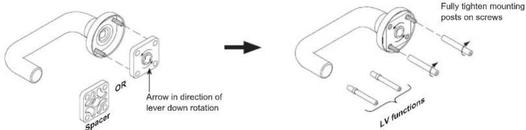
L9000-Series Installation Sheet—Page 2
4
All functions

OR
For Functions:
9486
9496

5
For Functions:
9040
9440

OR
For Functions:
9050
9056
9060
9070
9071
9076
9077
9080
9082
9453
9456
9457
9465
9466
9473
9480
9485
9486
9496

OR
For Functions:
9044
9444


L9000-Series Installation Sheet–Page 3
6 All functions

7 All functions


8 For Functions:

OR For Functions:

L9000-Series Installation Sheet—Page 4
9
All functions

10
All functions

Door Handing
IMPORTANT: Move handing screw to inside of door for L locks and outside of door for LV locks.

L9000-Series Installation Sheet—Page 5
Lever and Escutcheon
A Lockcase and mounting screws
B Spindle and spring
D Mounting posts
E Spring cage or spacer
G Inside mounting plate and screws
H Inside lever
K Cylinder and spring
N Emergency button and turn
Q Armor front and screws
R Outside lever and escutcheon
T Inside escutcheon and screws
IMPORTANT: Before installation of any L/LV Series lock, check lock handing. (See door handing section.)

1 All functions

2 All functions

3 All functions IMPORTANT: If spacer is supplied, install now.

L9000-Series Installation Sheet—Page 6
4
IMPORTANT: For concealed cylinder option, install cylinder(s) BEFORE installing escutcheon(s).

OR
For Functions:

5
For Functions:
9010
9176

OR
9070
9071
9076
9077
9080
9082
9453
9456
9457
9465
9466
9473
9480
For Functions:
9050 9485
9056 9486
9060 9496

OR
For Functions:
9040 9440

6
All functions

L9000-Series Installation Sheet–Page 7


L9000-Series Installation Sheet—Page 8
10
All functions

Door Handing
IMPORTANT: Move handing screw to inside of door for L locks and outside of door for LV locks.

11
All functions

L9000-Series Installation Sheet—Page 9
Knob and Rose
A Lockcase and mounting screws
B Spindle and spring
D Mounting posts
F Occupancy indicator
J Inside thumbturn
K Cylinder, compression ring and spring
L Inside rose
M Outside knob and rose
N Emergency turn and button
P Coin turn
Q Armor front and screws
V Knob mounting plate
W Inside knob
Z Blocking ring
IMPORTANT: Before installation of any L/LV Series lock, check lock handing. (See door handing section.)

1 All functions

3 All functions

2 All functions

4 All functions

L9000-Series Installation Sheet–Page 10
5
For Functions:
9040 9440

OR
For Functions:
9044
9444

OR
For Functions:
9486
9496

OR
For Functions:
9050
9056
9060
9070
9071
9076
9077
9080
9082
9453
9456
9457
9465
9466
9473
9480
9485
9486
9496


6
All functions

L9000-Series Installation Sheet—Page 11
7 All functions

OR For Functions:

8 For Functions:

9 All functions

L9000-Series Installation Sheet—Page 12
10
All functions

Door Handing
IMPORTANT: Move handing screw to inside of door.
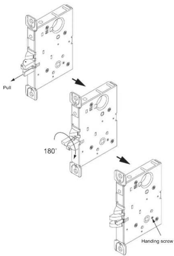
L9000-Series Installation Sheet–Page 13
Knob and Escutcheon
A Lockcase and mounting screws
B Spindle and spring
D Mounting posts
K Cylinder and spring
N Emergency button and turn
Q Armor front and screws
S Outside knob and escutcheon
T Inside escutcheon and screws
V Knob mounting plate
W Inside knob
IMPORTANT: Before installation of any L/LV Series lock, check lock handing. (See door handing section.)

1 All functions

3 All functions

2 All functions

4 IMPORTANT: For concealed cylinder option, install cylinder(s) BEFORE installing escutcheon(s).

L9000-Series Installation Sheet—Page 14
5
For Functions:
9010 9110 9176

OR
For Functions:
9040 9440

OR
For Functions:
9486
9496

OR
For Functions:
9050
9056
9060
9070
9071
9076
9077
9080
9082
9453
9456
9457
9465
9466
9473
9480
9485
9486
9496

6
All functions

L9000-Series Installation Sheet—Page 15
| 7 | For Functions: | ||||
| 9010 | 9071 | 9080 | 9175 | 9465 | |
| 9060 | 9076 | 9082 | 9176 | 9466 | |
| 9070 | 9077 | 9110 | 9457 | ||

| 8 | For Functions: | ||||
| 9050 | 9071 | 9082 | 9465 | 9485 | |
| 9056 | 9076 | 9453 | 9466 | 9486 | |
| 9060 | 9077 | 9456 | 9473 | 9496 | |
| 9070 | 9080 | 9457 | 9480 | ||

| OR | For Functions: | |
| 9040 | 9453 9485 | |
| 9050 | 9456 9486 | |
| 9056 | 9473 9496 | |
| 9440 | 9480 | |


L9000-Series Installation Sheet—Page 16
10
All functions

Door Handing
IMPORTANT: Move handing screw to inside of door.

11
All functions

L400-Series Installation Sheet—Page 1
Small Case Mortise Locks
A Lockcase and mounting screws
B Occupancy indicator
C Cylinder compression ring and spring
D Inside thumbturn
E Blocking ring
F Armor front and screws

1 All functions

OR For Functions:
L460
L462
L463
L464
L496

2 For Function: L496


L400-Series Installation Sheet—Page 2
3
For Functions:
L460
L480
L496

4
All functions

OR
For Function:
L462

5
All functions

OR
For Function:
L463

Ordering Procedures
To order Schlage products, descriptive data should be in the same sequence as shown:
| Line Item | Qty P | Product | Outside Inside | Hand L | Latch Strike | DR THK | EXT DIM | Additional Details | |||
| DES FIN DES FIN | |||||||||||
| 1 2 3 | 4 5 6 7 | 8 9 | 10 11 | 12 13 | 14 | ||||||
- Line Item: Line item number
- Qty: Quantity
- Product: Complete lock product or part number
- Outside DES: Outside design code
- Outside FIN: Outside finish code
- Inside DES: Inside design code: Leave blank if same as outside design code.
- Inside FIN: Inside finish code: Leave blank if same as outside finish code.
- Hand: Hand of door: Only one hand allowed per line item. Example: RH=Right Hand, LH=Left Hand, RR=Right Reverse, LR=Left Reverse
- Latch: Latch: Leave blank for standard or specify part number if non-standard latch is required. LLL=Less Latch.
- Strike: Strike: Leave blank for standard or specify part number if non-standard strike is required. LLL=Less Strike.
- DR THK: Door thickness: Enter door thickness if non-standard. Example: 138=13/8 , 214=21/4 , 212=21/2 .
- EXT: Extension: Enter one of the following when doors 2" thick or greater are specified: EE=Extended Equally, EI=Extended Inside, EO=Extended Outside, ED=Extended Differently. EI or EO assumes the latch with be centered on 13/4 " door, to which material has been added.
- DIM: Dimension: Enter dimension for non-standard strike lip length and mortise cylinder or blocking ring length.
0 1 2 = 1/8" 1 1 8 = 1 1/8"
0 1 8 = ^ 3 / 1 6" 1 1 4 = 1 ^ 1 / 4"
0 2 5 = 1 / 4" 1 3 8 = 1 ^ 3 / 8"
0 3 1 = ^ 5 / 1 6" 1 1 2 = 1 ^ 1 / 2"
0 3 7 = ^ 3 / 8" 1 5 8 = 1 ^ 5 / 8"
0 5 0 = 1 / 2 ^ 1 3 4 = 1 ^ 3 / 4
0 7 8 = 7 / 8 ^ 2 0 0 = 2 ^
1 0 0 = 1 ^ 4 0 0 = 4 ^
- Additional Details: Enter detail for keying information and for special requirements.
- Examples:
| Line Item | Qty | Product | Outside Inside | Hand L | Latch Strike | DR THK | EXT | DIM Additional Details | ||||
| DES FIN DES FIN | ||||||||||||
| One mortise cylinder, 1 1/4 " long, which will operate a Von Duprin exit device. | ||||||||||||
| 17 | 1 | 20-001 | 626 | 114 | ||||||||
| One hotel function L-Series lock with 17B trim in 625 for left hand door. | ||||||||||||
| 18 | 1 | L9485P | 17B | 625 | LH | 114 | ||||||
| Five replacement inside L escutcheons with “EZ” turn, in satin stainless steel, to be used with 06 lever on 13/4 ” doors. | ||||||||||||
| 19 | 5 | 09-633 | 06L | 630 | 134 | with EZ turn per L583-363 | ||||||
Finishes
Schlage Lock products are available in a range of durable, top quality finishes. Most are available with a clear coating that protects against damaging environmental factors, including sea air, high humidity, or corrosive vapors.
Cleaning and care varies by fi nish. Clear-coated or oil rubbed fi nishes can be cleaned periodically with a mild non-abrasive soap and buffed lightly with a clean cloth. Non-clear coated fi nishes should not be cleaned with soaps or solvents. They require cleaning with a clean, soft, damp cloth.
Finishes are coded according to the Builders Hardware Manufacturers Association (BHMA). The nearest old U.S. equivalent code designations are shown in parentheses.
Finish Codes and Descriptions
| Code Description | |
| 605 (US 3) Bright Brass, clear coated | |
| 606 (US 4) Satin Brass, clear coated | |
| 609 (US 5) Antique Brass, clear coated | |
| 612 (US 10) Satin Bronze, clear coated | |
| 613 (US 10B) Oil Rubbed Bronze, no coating | |
| 619 (US 15) Satin Nickel, clear coated | |
| 625 (US 26) Bright Chromium Plated, no coating | |
| 626 (US 26D) Satin Chromium Plated, no coating | |
| 626AM Satin Chromium Plated, Anti-Microbial coating | |
| 629 (US 32) Bright Stainless Steel, no coating | |
| 630 (US 32D) Satin Stainless Steel, no coating | |
| 630AM Satin Stainless Steel, Anti-Microbial coating | |
| 643e (US 11) Commercial Aged Bronze |
For fi nish availability refer to Schlage Commercial Price Book.
Limited Warranty
COMMERCIAL APPLICATION
3-Year Limited Warranty
Schlage Lock Company (the “Company”) extends a three-year limited warranty from the original date of purchase to the Original User of the products manufactured by the Company (the “Product”) against defects in material and workmanship. Certain Products contain restrictions to this limited warranty, additional warranties or different warranty periods. Please see below for specific Product warranty information.
The provisions of this warranty do not apply to Products: (i) used for purposes for which they are not designed or intended; (ii) which have been subjected to alteration, abuse, misuse, negligence or accident; (iii) which have been improperly stored, installed, maintained or operated; (iv) which have been used in violation of written instructions provided by Schlage; (v) which have been subjected to improper temperature, humidity or other environmental conditions (i.e., corrosion); or (vi) which, based on Schlage's examination, do not disclose to Schlage's satisfaction non-conformance to the warranty. Additionally, Schlage will not warrant ANSI A156.2 Grade 2 lever Product installed in educational facilities and student housing.
SPECIFIC PRODUCT WARRANTY RESTRICTIONS / ADDITIONAL WARRANTIES
Portable Security Products Warranty: A limited lifetime warranty is provided to the Original User, subject to the restrictions of this limited warranty, except that the Company's sole obligation under this warranty is to replace the Product.
ND-Series Levers 7-Year Mechanical Warranty: A limited warranty is provided to the Original User for seven (7) years from original date of purchase, subject to the restrictions of this limited warranty.
Small Format Interchangeable Core (SFIC) Warranty: This limited warranty also applies to Schlage locks and housings when used with another manufacturer's cores, or to Schlage cores (i.e. SFIC) when used in another manufacturer's locks and housings. The use of unauthorized cylinder cams or other components with the Products shall void this warranty.
Everest® Primus® Limited Lifetime Key Breakage Warranty: A limited lifetime warranty is provided to the Original User against key breakage, subject to the restrictions of this limited warranty.
Cobra, CM and PRO-Series 1-Year Electronic Lock Warranty: A limited warranty is provided to the Original User for one (1) year from original date of purchase, subject to the restrictions of this limited warranty.

Ingersoll Rand
Security Technologies
Ingersoll Rand's Security Technologies Sector is a leading global provider of products and services that make environments safe, secure and productive. The Sector's market-leading products include electronic and biometric access control systems; time and attendance and personnel scheduling systems; mechanical locks and portable security, door closers and exit devices, steel doors and frames, architectural hardware and technologies and services for global security markets.
877.671.7011 www.schlage.com www.ingersollrand.com


- L-SERIES SERVICE MANUAL
- CONTENTS
- INTRODUCTION
- LOCK ASSEMBLY DRAWING INDEX
- TRIM ASSEMBLIES
- BLANK
- LOCK CASE ASSEMBLIES
- LV9080EL
- LV9080EU
- L9082EU
- LV
- ASSEMBLY OF LOCK CASE PARTS
- TURN HUB SPRING AND TRANSFER LEVER
- LOCKING CATCH / RETRACTOR CATCH AND LOCKING LINK
- TRIM OPTIONS
- CAST OR FORGED LEVER DESIGNS
- WROUGHT KNOB DESIGNS
- ROSE TRIM A OR B INSIDE ROSE BLANK OUTSIDE ROSE
- OUTSIDE ROSE DIMENSIONS
- L ESCUTCHEON TRIM
- OUTSIDE ESCUTCHEON DIMENSIONS
- KNOB/LEVER DESIGN
- OUTSIDE ESCUTCHEONS
- INSIDE ESCUTCHEONS
- N ESCUTCHEON TRIM
- (INCLUDES TWO (2) SCREWS AND MOUNTING PLATE)
- DECORATIVE TRIM
- DECORATIVE LEVERS
- DECORATIVE ROSES
- INSIDE LEVER ASSEMBLY
- OUTSIDE LEVER ASSEMBLY
- DANMARK STAINLESS STEEL LEVERS
- TACTILE WARNING (KNURLING)
- TRIM ASSEMBLY PARTS
- ESCUTCHEON THRU-BOLT/SCREWS
- DRIVERS TO OPERATE OCCUPANCY INDICATOR
- MOUNTING POSTS SPINDLES AND SPRINGS
- MOUNTING PLATE FOR TRIM ONE SIDE ONLY
- SCHLAGE®
- INSTALLATION INSTRUCTIONS
- ANSI A115.1 1990 HOLLOW STEEL DOOR INSTALLATIONS
- STRIKES
- CYLINDER SPECIFICATIONS
- HOW TO MEASURE CYLINDER LENGTHS
- FULL FACE CYLINDERS
- CONCEALED CYLINDERS
- FULL SIZE INTERCHANGEABLE CORES
- SMALL FORMAT INTERCHANGEABLE CORE
- EXPLODED VIEW – SMALL FORMAT EVEREST® KEYWAYS
- BLOCKING AND COMPRESSION RINGS
- SPECIAL OPTIONS
- INSTALLATION TOOLS AND KITS
- ELECTRICALLY LOCKING
- L9080 EL ELECTRICALLY LOCKED (FAIL SAFE)
- L9080 EU ELECTRICALLY UNLOCKED (FAIL SECURE)
- REQUEST TO EXIT (RX) FEATURE
- L9082 EL OR EU ELECTRICALLY LOCKED OR UNLOCKED BOTH SIDES
- CYLINDERS
- REPLACEMENT KIT
- ELECTRICAL REQUIREMENTS
- TYPICAL INSTALLATION
- DOOR HANDING
- CHANGING THE LOCK HAND
- CHANGING CYLINDER TURN HAND
- L9000-SERIES INSTALLATION SHEET—PAGE
- LEVER AND ROSE
- L9000-SERIES INSTALLATION SHEET–PAGE
- LEVER AND ESCUTCHEON
- KNOB AND ROSE
- KNOB AND ESCUTCHEON
- L400-SERIES INSTALLATION SHEET—PAGE
- SMALL CASE MORTISE LOCKS
- ORDERING PROCEDURES
- FINISHES
- LIMITED WARRANTY
- COMMERCIAL APPLICATION
- YEAR LIMITED WARRANTY
- SPECIFIC PRODUCT WARRANTY RESTRICTIONS / ADDITIONAL WARRANTIES
- INGERSOLL RAND
Brand : Schlage
Model : L9071
Category : Uncategorized