
P621U-W - Projector SHARP - Free user manual and instructions
Find the device manual for free P621U-W SHARP in PDF.


| Product Type | Projector |
| Brand | Sharp |
| Model | P621U-W |
| Display Technology | DLP |
| Native Resolution | 1024 x 768 (XGA) |
| Brightness | 3200 ANSI lumens |
| Contrast Ratio | 2000:1 |
| Lamp Life | 3000 hours (up to 4000 in eco mode) |
| Projection Ratio | 1.5 - 1.8:1 |
| Keystone Correction | Automatic vertical correction |
| Zoom | Optical zoom 1.2x |
| Connections | VGA, S-Video, composite, audio in/out |
| Input Power | AC 100-240V, 50/60Hz |
| Power Consumption | 310W (standby 0.5W) |
| Dimensions (W x D x H) | 350 x 250 x 110 mm |
| Weight | 3.5 kg |
| Cleaning | Lens and air filter maintenance |
| Security | Kensington lock slot and password protection |
| Spare Parts | Replacement lamp and air filter available |
| General Information | User manual in English, 132 pages |
Frequently Asked Questions - P621U-W SHARP
User questions about P621U-W SHARP
0 question about this device. Answer the ones you know or ask your own.
Ask a new question about this device
Download the instructions for your Projector in PDF format for free! Find your manual P621U-W - SHARP and take your electronic device back in hand. On this page are published all the documents necessary for the use of your device. P621U-W by SHARP.
USER MANUAL P621U-W SHARP
1. Check the product overview, supplied items and part names .... 1
1-1. Introduction to the Projector .... 1
1-2. What's in the Box? 4
1-3. Part Names of the Projector .... 5
1-4. Part Names of the Remote Control 11
2. Projecting an Image (Basic Operation) 17
2-1. Flow of Projecting an Image 17
2-2. Connecting Your Computer/Connecting the Power Cord 18
2-3. Turning on the Projector 20
2-4. Selecting a Source 22
2-5. Adjusting the Picture Size and Position 23
2-6. Adjusting for Trapezoidal Distortion (Keystone Correction) 29
2-7. Adjusting the unit's volume 32
2-8. Turning off the Projector 33
2-9. When Moving the Projector 34
3. Convenient Features ...... 35
3-1. Muting the picture and sound (AV-MUTE) 35
3-2. Freezing a movie (still image) 35
3-3. Zooming part of the picture (Partial Zoom) 36
3-4. Adjusting the luminance (brightness) (Light mode) 37
4. Using the Viewer (USB-A) 39
4-1. What you can do with the Viewer 39
4-2. Projecting images stored on USB flash drives (basic operation) 40
5. Using On-Screen Menu 42
5-1. Basic Operations of the On-Screen Menu 42
5-2. On-screen menu list 45
5-3. PICTURE 48
5-4. IMAGE OPTIONS 50
5-5. SETUP (1) 53
5-6. SETUP(2) 57
5-7. USB-A 69
5-8. INFORMATION 70
6. Making Connections ...... 71
6-1. Connecting to Computers and Video Devices 71
6-2. Connecting to a Wired LAN 72
6-3. Connecting to a HDBaseT transmission device (sold commercially) 73
6-4. Portrait projection (vertical orientation) 75
7. Connecting to a Network 78
7-1. What You Can Do by Connecting to a Network 78
7-2. Enabling the projector's wired LAN function 78
7-3. Connecting to the projector's HTTP server 80
7-4. Registering the Background Logo 84
8. Maintenance 85
8-1. Cleaning the Lens 85
8-2. Cleaning the Cabinet 86
9. Appendix 87
9-1. Setting Up the Screen and the Projector 87
9-2. Compatible Input Signal List 91
9-3. Specifications 92
9-4. Cabinet Dimensions 95
9-5. Pin assignments and signal names of main terminals 96
9-6. PC Control Codes and Cable Connection 98
9-7. About the ASCII Control Command 100
9-8. Troubleshooting 102
9-9. Indicator Message 104
9-10. Troubleshooting Check List 107
Introduction
Thank you for purchasing the projector.
This projector can be connected to computers, video devices, etc. to project images sharply onto a screen.
Please read this manual carefully before using your projector.
Read this manual if you have any doubts about operation or if you believe the projector may be faulty.
NOTES
(1) The contents of this manual may not be reprinted in part or whole without permission.
(2) The contents of this manual are subject to change without notice.
(3) Great care has been taken in the preparation of this manual; however, should you notice any questionable points, errors or omissions, please contact us.
(4) The image shown in this manual is indicative only. If there is inconsistency between the image and the actual product, the actual product shall govern.
(5) Notwithstanding article (3) and (4), we will not be responsible for any claims on loss of profit or other matters deemed to result from using this device.
(6) This manual is commonly provided to all regions so they may contain descriptions that are pertinent for other countries.
FCC Information (for USA only)
Supplier's Declaration of Conformity
This device complies with Part 15 of the FCC Rules. Operation is subject to the following two conditions: (1) This device may not cause harmful interference, and (2) this device must accept any interference received, including interference that may cause undesired operation.
Responsible Party: SHARP ELECTRONICS CORPORATION
100 Paragon Drive, Montvale, NJ 07645
TEL: 1-888-GO-SHARP / 1-888-467-4277 www.sharpusa.com
WARNING:
FCC Regulations state that any unauthorized changes or modifications to this equipment not expressly approved by the manufacturer could void the user's authority to operate this equipment.
NOTE:
This equipment has been tested and found to comply with the limits for a Class A digital device, pursuant to Part 15 of the FCC Rules. These limits are designed to provide reasonable protection against harmful interference when the equipment is operated in a commercial environment. This equipment generates, uses, and can radiate radio frequency energy and, if not installed and used in accordance with the instruction manual, may cause harmful interference to radio communications.
Operation of this equipment in a residential area is likely to cause harmful interference in which case the user will be required to correct the interference at his own expense.
U.S.A. ONLY
Cable information
Use shielded cables to prevent interference with radio or television reception.
Notice Concerning Electromagnetic Interference (EMI) (For other regions)
WARNING:
Operation of this equipment in a residential environment could cause radio interference.
(For Customers in U.K.)
IMPORTANT
- The wires in this mains lead are coloured in accordance with the following code:
GREEN-AND-YELLOW: "Earth"
BLUE: "Neutral"
BROWN: "Live"
- As the colours of the wires in the mains lead of this apparatus may not correspond with the coloured markings identifying the terminals in your plug proceed as follows:
- The wire which is coloured GREEN-AND-YELLOW must be connected to the terminal in the plug which is marked by the letter E or by the safety earth symbol 1/2 or coloured green or green-and-yellow.
- The wire which is coloured BLUE must be connected to the terminal which is marked with the letter N or coloured black.
- The wire which is coloured BROWN must be connected to the terminal which is marked with the letter L or coloured red.
- Ensure that your equipment is connected correctly. If you are in any doubt consult a qualified electrician.
"WARNING: THIS APPARATUS MUST BE EARTHED."

Information on the Disposal of this Equipment and its Batteries
IF YOU WISH TO DISPOSE OF THIS EQUIPMENT OR ITS BATTERIES, DO NOT USE THE ORDINARY WASTE BIN, AND DO NOT PUT THEM INTO A FIREPLACE!
Used electrical and electronic equipment and batteries should always be collected and treated SEPARATELY in accordance with local law.
Separate collection promotes an environment-friendly treatment, recycling of materials, and minimizing final disposal of waste. IMPROPER DISPOSAL can be harmful to human health and the environment due to certain substances! Take USED EQUIPMENT to a local, usually municipal, collection facility, where available.
Remove USED BATTERIES from equipment, and take them to a battery collection facility; usually a place where new batteries are sold.
If in doubt about disposal, contact your local authorities or dealer and ask for the correct method of disposal.
ONLY FOR USERS IN THE EUROPEAN UNION, AND SOME OTHER COUNTRIES; FOR INSTANCE NORWAY AND SWITZERLAND: Your participation in separate collection is requested by law.
The symbol shown above appears on electrical and electronic equipment and batteries (or the packaging) to remind users of this. If 'Hg' or 'Pb' appears below the symbol, this means that the battery contains traces of mercury (Hg) or lead (Pb), respectively.
Users from PRIVATE HOUSEHOLDS are requested to use existing return facilities for used equipment and batteries.
Batteries are collected at points of sale. Return is free of charge.
If the equipment has been used for BUSINESS PURPOSES, please contact your SHARP dealer who will inform you about take-back. You might be charged for the costs arising from take-back.
Small equipment (and small quantities) might be taken back by your local collection facility.
For Spain: Please contact the established collection system or your local authority for take-back of your used products.
(for Germany only)
Machine Noise Information Regulation - 3. GPSGV,
The highest sound pressure level is less than 70 dB (A) in accordance with EN ISO 7779.
Information of the AUDIO OUT mini jack
The AUDIO OUT mini jack does not support earphone/headphone terminal.
Laser Safety Caution

WARNING
CLASS 1 LASER PRODUCT [IEC 60825-1:2014]
CLASS 1 CONSUMER LASER PRODUCT OF EN 60825-1:2014+A11:2021 (For EU and UK)
- The laser module is equipped in this product. Use of controls or adjustments of procedures other than those specified herein may result in hazardous radiation exposure.
Laser energy exposure near aperture may cause burns.
• This product is classified as Class 1 of IEC 60825-1:2014.
- For EU and UK, EN 60825-1:2014+A11:2021 and EN 50689:2021 are also conformed.
- Obey the laws and regulations of your country in relation to the installation and management of the device.
For USA
Complies with 21 CFR 1040.10 and 1040.11 except for conformance as a Risk Group 2 LIP as defined in IEC 62471-5:Ed. 1.0. For more information see Laser Notice No. 57, dated May 8, 2019.

WARNING
- Do not allow to look into the projector beam at any distance from the projector. An adult should supervise the children to prevent exposure risks.
- Check that there is no one looking at the lens, when using the remote control for starting the projector.
- Do not look at the projected light using optical devices(binoculars, telescopes, magnifying glasses, reflectors, etc).
- [WARNING: MOUNT ABOVE THE HEADS OF CHILDREN.]
The use of a ceiling mount is recommended with this product to place it above the eyes of children.
- Outline of laser emitted from the built-in light module:
- Wave length: 449 - 461 nm
- Maximum power: 180 W (P701U-W), 129 W (P621U-W)
Light Module
- A light module containing multiple laser diodes is equipped in the product as the light source.
- These laser diodes are sealed in the light module. No maintenance or service is required for the performance of the light module.
- End user is not allowed to replace the light module.
- Contact qualified distributor for light module replacement and further information.
Risk groups
This projector is classified as risk group 2 of IEC/EN 62471-5:2015.

WARNING
As with any bright light source, do not stare into the beam, RG2 IEC/EN 62471-5:2015.
About the symbols
To ensure safe and proper use of the product, this manual uses a number of symbols to prevent injury to you and others as well as damage to property.
The symbols and their meanings are described below. Be sure to understand them thoroughly before reading this manual.
 WARNING WARNING | Failing to heed this symbol and handling the product erroneously could result in accidents leading to death or major injury. |
 CAUTION CAUTION | Failing to heed this symbol and handling the product erroneously could result in personal injury or damage to surrounding property. |
Examples of symbols
 | This symbol indicates you should be careful of electric shocks. |
 | This symbol indicates you should be careful of high temperatures. |
 | This symbol indicates something that must be prohibited. |
 | This symbol indicates something that must not be got wet. |
 | This symbol indicates you should not touch with wet hands. |
 | This symbol indicates something that must not be disassembled. |
 | This symbol indicates things you must do. |
 | This symbol indicates that the power cord should be unplugged from the power outlet. |
Safety Cautions

WARNING
Projected light

PROHIBITED
Projected light and the pictogram/label indicated on the cabinet
- Do not look into the projector's lens.
Strong light that could damage your vision is projected when the projector is operating. Laser energy exposure near aperture may cause burns. Be especially careful when children are around. - Do not look at the projected light using optical devices (magnifying glasses, reflectors, etc.). Doing so could result in vision impairment.
- Check that there is no one looking at the lens within the projection range before turning on the projector.
- Do not allow children to operate the projector alone. When a child is operating the projector an adult should always be present and watch the child carefully.
- The below pictogram, that is indicated near the lens on the cabinet, describes looking into the projector is prohibited.

Continue to next page

WARNING
• The following labels are stuck on the projector.
Label 1
Laser explanatory label
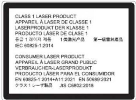
Label 2
FDA additional warning label (For USA only)


Label 2

| WARNING | |
| Power supply | |
 REQUIRED REQUIRED | Use a suitable voltage power supply.This projector is designed to be used with a 100–240 VAC, 50/60 Hz power supply. Before using the projector, check that the power supply to which the projector is to be connected meets these requirements.Use a power outlet as the projector's power supply. Do not connect the projector directly to electrical light wiring. Doing so is dangerous. |
 MUST BE EARTHED MUST BE EARTHED | Connecting the power cord to earthThis equipment is designed to be used in the condition of the power cord connected to earth. If the power cord is not connected to the earth, it may cause electric shock. Please make sure the power cord is connected to the wall outlet directly and earthed properly.Do not use a 2-pin plug converter adapter.Be sure to connect the projector and the computer (signal source) to the same earth point. If the projector and the computer (signal source) will be connected to different earth points, fluctuations in the earth potential may cause fire or smoke. |
 REQUIRED REQUIRED | Handling the power cordPlease use the power cord supplied with this projector. If the supplied power cord does not satisfy requirements of your country's safety standard, and voltage and current for your region, make sure to use the power cord that conforms to and satisfies them. The power cord you use must be approved by and comply with the safety standards of your country. Please refer to the page 93 about the power cord specification.For selecting an appropriate power cord, please check rated voltage for your region by yourself. The power cord you use must be approved by and comply with the safety standards of your country. Please refer to the page 93 about the power cord specification.For selecting an appropriate power cord, please check rated voltage for your region by yourself. |
 PROHIBITED PROHIBITED | The power cord included with this projector is exclusively for use with this projector. For safety, do not use it with other devices. |
 HAZARDOUS VOLTAGE HAZARDOUS VOLTAGE DO NOT TOUCH WITH WET HANDS DO NOT TOUCH WITH WET HANDS | · Handle the power cord with care. Damaging the cord could lead to fire or electric shock.- Do not place heavy objects on the cord.- Do not place the cord under the projector.- Do not cover the cord with a rug, etc.- Do not scratch or modify the cord.- Do not bend, twist or pull the cord with excessive force.- Do not apply heat to the cord.Should the cord be damaged (exposed core wires, broken wires, etc.), ask your dealer to replace it.· Do not touch the power plug should you hear thunder. Doing so could result in electric shock.· Do not connect or disconnect the power cord with wet hands. Doing so could result in electric shock. |
| Installation | |
 PROHIBITED PROHIBITED DO NOT WET DO NOT WET UNPLUG THE POWER CORD UNPLUG THE POWER CORD | Do not use in places such as those described below.· Do not use in places such as those described below. Doing so could lead to fire or electric shock.- Shaky tables, inclined surfaces or other unstable places.- Poorly ventilated spaces.- Near a radiator, other heat sources, or in direct sunshine.- Continual vibration areas.- Humid, dusty, steamy, or oily areas.- An environment where there are corrosive gases (sulfur dioxide, hydrogen sulfide, nitrogen dioxide, chlorine, ammonia, ozone, etc.).- Outdoors.- High-temperature environment where humidity changes rapidly and condensation is likely to occur.· Do not use in places such as those described below where the projector could get wet. Doing so could lead to fire or electric shock.- Do not use in the rain or snow, on a seashore or waterfront, etc.- Do not use in a bathroom or shower room.- Do not install under equipment that discharges water, such as air conditioners.- Do not place vases or potted plants on the projector.- Do not place cups, cosmetics or medicines on the projector.Should water, etc. get inside the projector, first turn off the projector's power, then unplug the power cord from the power outlet and contact your dealer. |
 CAUTION CAUTION | Installing suspended from the ceilingConsult your dealer for installing the projector on the ceiling. Special skills are required for ceiling installation.DO NOT perform installation work by people other than installers. Doing so may result in the projector falling and causing injury.We are not liable for any accident or/and damage resulting from improper installation or handling, misuse, modification, or natural disasters.When installed suspended from the ceiling, etc. do not hang from the projector. The projector could drop and cause injury.When installing suspended from the ceiling, use a power outlet that is within reach so the power cord can be easily plugged and unplugged. |
| On use | |
 PROHIBITED PROHIBITED UNPLUG THE POWER CORD UNPLUG THE POWER CORD | Do not place objects inside the projector.Do not insert or drop metal or combustible objects or other foreign materials into the projector from the vents. Doing so could lead to fire or electric shock. Be particularly careful if there are children in the home. Should a foreign object get inside the projector, first turn off the projector's power, then unplug the power cord from the power outlet and contact your dealer. |
 UNPLUG THE POWER CORD UNPLUG THE POWER CORD | Unplug the power cord if the projector malfunctions.Should the projector emit smoke or strange odors or sounds, or if the projector has been dropped or the cabinet broken, turn off the projector's power, then unplug the power cord from the power outlet. Otherwise it may cause not only fire or electric shock but also serious damage to your eyesight or burns. Contact your dealer for repairs.Never try to repair the projector on your own. Doing so is dangerous. |
 DO NOT DISASSEMBLE DO NOT DISASSEMBLE | Do not disassemble the projector.Do not remove or open the projector's cabinet.Also, do not modify the projector. There are high voltage areas in the projector. It may cause fire, electric shock, or laser light leakage, resulting in serious damage to your eyesight or burns.Have qualified service personnel perform inspection, adjustments and repairs of the interior. |
  | |
| PROHIBITEDCAUTION FOR HIGH TEMPERATURE | Do not place objects in front of the lens while the projector is operating.Do not leave the lens cap on the lens while the projector is operating. The lens cap could get hot and be warped.Do not place objects in front of the lens that obstruct the light while the projector is operating. The object could get hot and be broken or catch fire.The below pictogram indicated on the cabinet means the precaution for avoiding to place objects in front of the projector lens.[IMAGE] |
| PROHIBITED | When cleaning the projectorDo not use flammable gas sprays to remove dust from the lens, cabinet, etc. Doing so could lead to fire. |
| PROHIBITED | Do not use in high security locations.Usage of the product must not be accompanied by fatal risks or dangers that, could lead directly to death, personal injury, severe physical damage or other loss, including nuclear reaction control in nuclear facility, medical life support system, and missile launch control in a weapon system. |
| CAUTION | |
| Power cord | |
 REQUIRED REQUIRED | Handling the power cordThe projector should be installed close to an easily accessible power outlet.When connecting the power cord to the projector's AC IN terminal, make sure the connector is fully and firmly inserted. Loose connection of the power cord could lead to fire or electric shock. |
 REQUIRED REQUIRED UNPLUG THE POWER CORD UNPLUG THE POWER CORD | Handling the power cord by following below to avoid fire or electric shockWhen disconnecting the power cord, pull the power cord out by holding onto its plug.Unplug the power cord from the power outlet before cleaning the product or when not planning to use the product for an extended time.When the power cord or plug is heat or damaged, unplug the power cord from the power outlet, and contact your dealer. |
 REQUIRED REQUIRED | Periodically clean dust and other debris from the power plugFailure to do so could result in fire or electric shock. |
 REQUIRED REQUIRED | Disconnect power cords and other cables before moving the projectorBefore moving the product, make sure the product power is off, then unplug the power cord from the power outlet and check that all cables connecting the product to other devices are disconnected. |
 PROHIBITED PROHIBITED | Do not use the power cord with a power tapAdding an extension cord may lead to fire as a result of overheating. |
| On use | |
 PROHIBITED PROHIBITED | Do not use on networks subject to overvoltage.·Connect the projector's HDBaseT port and LAN port to a network for which there is no risk of overvoltage being applied.Overvoltage applied to the HDBaseT or LAN port could result in electric shock. |
 REQUIRED REQUIRED | Lens shift, focus and zoom operations·When shifting the lens or adjusting the focus or zoom, do so from either behind or the side of the projector. If adjustments are performed from the front, your eyes could be exposed to strong light and get injured.·Keep your hands away from the lens area when performing the lens shift operation. If not, your fingers could get caught in the gap between the cabinet and the lens. |
 PROHIBITED PROHIBITED | Handling batteriesIncorrect usage of batteries can result in leaks or bursting.·Use the specified batteries only.·Insert batteries matching the (+) and (−) signs on each battery to the (+) and (−) signs of the battery compartment.·Do not mix battery brands.·Do not combine new and old batteries. This can shorten battery life or cause liquid leakage of batteries.·Remove dead batteries immediately to prevent battery acid from leaking into the battery compartment.If leaked battery fluid gets on your skin or clothing, rinse immediately and thoroughly. If it gets into your eye, bathe your eye well rather than rubbing and seek medical treatment immediately. Leaked battery fluid that gets into your eye or your clothing may cause a skin irritation or damage your eye.·If you will not use the remote control for a long time, remove the batteries.·Leaving a battery in an extremely high temperature surrounding environment, or a battery subject to extremely low air pressure, that can result in an explosion or the leakage of flammable liquid or gas.·Properly dispose of depleted batteries. Disposal of a battery into water, fire, or a hot oven, or mechanically crushing, cutting, or modifying a battery can result in an explosion.·Do not short-circuit the batteries.·Do not charge the batteries. The batteries provided are not rechargeable.·Contact your dealer or local authorities when disposing of batteries. |
 PROHIBITED PROHIBITED CAUTION FOR HIGH TEMPERATURE CAUTION FOR HIGH TEMPERATURE | About the ventsDo not obstruct the projector's vents. Also, do not place such soft objects as paper or cloths underneath the projector. Doing so could lead to fire.Leave sufficient space between the place where the projector is installed and its surroundings. (→ page xxi)Do not touch the exhaust vent area while projecting or immediately after projecting images. The exhaust vent area may be hot at this time and touching it could cause burns. |
 PROHIBITED PROHIBITED | Moving the projectorWhen moving the projector, do not hold the lens section. The focus ring could turn, causing the projector to drop and resulting in injury. Also, if you put your hand on the gap between the cabinet and the lens, the projector may be damaged, falling and causing injury.Do not put your hand into the recess of the connection terminal. The projector could be damaged or fall down, resulting in injuries. |
 PROHIBITED PROHIBITED | Do not push or climb on the product. Do not grab or hang onto the product. Do not rub or tap the product with hard objects.The product may fall, causing damage to the product or personal injury. |
 REQUIRED REQUIRED | Avoid locations with extreme temperatures and humidityFailure to do so could lead to fire or electric shock or damage to the projector. The usage environment for this projector is as follows:The operating temperature: 0°C to 45°C / 32°F to 113°F / humidity: 20 to 80% (without condensation)- The storage temperature: -10°C to 50°C / 14°F to 122°F / humidity: 20 to 85% (without condensation) |
| Inspections and Cleaning | |
 REQUIRED REQUIRED | Inspecting the projector and cleaning the insideConsult with your dealer about once per year for cleaning of the inside of the projector. Dust could accumulate inside of the projector if it is not cleaned for extended periods of time, leading to fires or malfunction. |
Notes on installation and maintenance
Do not install or store in such places as those described below.
- Locations that amplify vibrations and impacts
If installed in places where the vibrations from power sources and the like are conveyed, or in vehicles or on vessels, etc. the projector could be affected by vibrations or shocks that may damage internal parts and lead to malfunction. - Close to high voltage power lines and power sources
It could disrupt the unit. - Places where strong magnetic fields are generated
Doing so could lead to malfunction. - Outdoors and places with humid or dust
Places exposed to oil smoke or steam
Places where corrosive gases are generated
Attached substances such as oil, chemicals and moisture may cause deformation or cracks of the cabinet, corrosion of the metal parts, or malfunction.
Precautions when installing on the ceiling (To the dealer and the installer)
- To prevent the projector from falling, install it on the ceiling in a way with sufficient strength to withstand the combined weight of the projector and the ceiling mount unit for an extended period of time.
- When installing the projector on the ceiling, be sure to do so correctly in accordance with the installation manual for the Ceiling Mount Unit. Be sure to use the fixed metal fittings and to tighten the screws securely.
- To prevent the projector from falling, use fall prevention wires.
- Use commercially available metal fittings to join the robust part of a building or construction and the security bar of the projector with the fall prevention wires.
- Use commercially available metal fittings and fall prevention wires that have sufficient strength to withstand the combined weight of the projector and the ceiling mount unit.
- Slightly slack off the fall prevention wires so as not to put a load on the projector.
- Refer to the "Part Names of the Projector" for the location of the security bar. (→ page 5)
Securing personal information
Personally identifiable information, such as IP addresses, may be saved on the projector.
Before transferring or disposing of the projector, clear this data by performing [RESTORE FACTORY SETTINGS] on the on-screen menu.
Cautions for ensuring the projector's performance
- If intense light like laser beams enters from the lens, it could lead to malfunction.
- Consult your dealer before using in places where much cigarette smoke or dust is present.
- When the same still image is projected for a long period of time with a computer, etc. the pattern of the image may remain on the screen after the projection is stopped, but it will disappear after a while. This happens due to the properties of liquid crystal panels, and is not a malfunction. We recommend using a screensaver on the computer side.
- When using the projector at altitudes of about 5500 feet/ 1600 meters or higher, be sure to set the [FAN MODE] to [HIGH ALTITUDE]. If not, the inside of the projector may get hot, leading to malfunction.
- When the projector is used at high altitudes (places where the atmospheric pressure is low), it may be necessary to replace the optical parts sooner than usual.
- About moving the projector
- Be sure to mount the included lens cap to protect the lens from scratches.
- Do not subject the projector to vibrations or strong shocks.
The projector could be damaged otherwise.
- Do not use the tilt feet for purposes other than adjusting the projector's tilt.
Improper handling, such as carrying the projector by the tilt feet or using it leaned against a wall, could lead to malfunction. - Do not touch the surface of the projection lens with bare hands.
Fingerprints or dirt on the surface of the projection lens will be enlarged and projected on the screen. Do not touch the surface of the projection lens. - Do not unplug the power cord from the projector or the power outlet while projecting. Doing so could cause deterioration of the projector's AC IN terminal or power plug contact. To interrupt the AC power supply while images are being projected, use a breaker, etc.
-
About handling of the remote control
-
The remote control will not work if the projector's remote signal sensor or the remote control's signal transmitter is exposed to strong light or if there are obstacles between them that obstruct the signals.
- Operate the remote control from within 23 feet / 7 meters from the projector, pointing it at the projector's remote signal sensor.
- Do not drop the remote control or handle it improperly.
- Do not let water or other liquids get on the remote control. Should the remote control get wet, wipe it off immediately.
- Avoid using in hot and humid places as far as possible.
• Take measures to prevent external light from shining on the screen.
Make sure only the light from the projector shines on the screen. The less external light on the screen, the higher the contrast and the more beautiful the images.
- About screens
Images will not be clear if there is dirt, scratches, discoloration, etc. on your screen. Handle the screen with care, protecting it from volatile substances, scratches and dirt.
Clearance for Installing the Projector
- When installing the projector, keep sufficient space around it, as described below. If not, the hot exhaust emitted from the projector may be taken back in.
Also, make sure no wind from an air-conditioner hits the projector.
The projector's heat control system may detect an abnormality (temperature error) and automatically shut off the power.

a: Exhaust vent / b: 20 cm/8" or greater
NOTE:
- In the above figure, it is assumed that there is sufficient space above the projector. There is also an intake vent on the back. Leave about 10 cm or more space behind, and even more space for installing the cables.
About Copyright of original projected pictures:
Please note that using this projector for the purpose of commercial gain or the attraction of public attention in a venue such as a coffee shop or hotel and employing compression or expansion of the screen image with the following functions may raise concern about the infringement of copyrights which are protected by copyright law.
[ASPECT RATIO], [KEYSTONE], Magnifying feature and other similar features.
Power management function
The projector has power management functions. To reduce power consumption, the power management functions (1 and 2) are factory preset as shown below. To control the projector from an external device via a LAN or serial cable connection, use the on-screen menu to change the settings for 1 and 2.
1. STANDBY MODE (Factory preset: NORMAL)
To control the projector from an external device, select [NETWORK STANDBY] or [SLEEP] for [STANDBY MODE].
2. POWER MANAGEMENT (Factory preset: READY)
To control the projector from an external device, select [OFF] for [POWER MANAGEMENT].
NOTE:
- If [POWER MANAGEMENT] mode is set to [READY] or [SHUT DOWN], the projector will automatically turn off if no input signal is received or the projector is not operated within the time set for [TIMER] and [READY COUNTDOWN] in the same settings.
REGISTER YOUR PROJECTOR! (for residents in the United States and Mexico)
Please take time to register your new projector. This will activate your limited parts and labor warranty and InstaCare service program.
Visit our website at https://www.sharpnecdisplays.us/product-registration and submit your completed form online.
Upon receipt, we will send a confirmation letter with all the details you will need to take advantage of fast, reliable warranty and service programs from the industry leader, Sharp Imaging and Information Company of America.
Registration Information and Software License
- Microsoft and Windows are either a registered trademark or trademark of Microsoft Corporation in the United States and/or other countries.
- The terms HDMI, HDMI High-Definition Multimedia Interface, HDMI Trade dress and the HDMI Logos are trademarks or registered trademarks of HDMI Licensing Administrator, Inc.
- HDBaseT™ and the HDBaseT Alliance logo are trademarks of the HDBaseT Alliance.
- Trademark PJLink is a trademark applied for trademark rights in Japan, the United States of America and other countries and areas.
- Blu-ray is a trademark of Blu-ray Disc Association.
- CRESTRON and CRESTRON ROOMVIEW are trademarks or registered trademarks of Crestron Electronics, Inc. in the United States and other countries.
• AMX is a registered trademark of AMX LLC of the United States. - Other product and company names mentioned in this user's manual may be the trademarks or registered trademarks of their respective holders.
• Virtual Remote Tool uses WinI2C/DDC library, © Nicomsoft Ltd.
• GPL/LGPL Software Licenses
The product includes software licensed under GNU General Public License (GPL), GNU Lesser General Public License (LGPL), and others.
For more information on each software, visit our web site.
https://www.sharp-nec-displays.com/dl/en/pj_manual/lineup.html
1. Check the product overview, supplied items and part names
1-1. Introduction to the Projector
This section introduces you to your new projector and describes the features and controls.
General
- Liquid crystal type high brightness/high resolution projector
| Model name Brightness Resolution Aspect ratio | |||
| P701U-W | 7000 lm(Center 7400 lm) | WUXGA(1920 × 1200 pixels) | 16:10 |
| P621U-W | 6200 lm(Center 6500 lm) | WUXGA(1920 × 1200 pixels) | 16:10 |
It also supports input signals with an aspect ratio of 21:9.
- A proprietary sealed structure that achieves highly dust-proof performance
Due to its excellent dust-proof performance, the projector is not equipped with a filter. Filter replacement is therefore unnecessary.
- Silent design utilizing a sealed structure
A silent design with no irritating fan noise even in a quiet conference room or classroom.
- Stable, high-definition image projection for extended periods of time
The sealed structure prevents dust from adhering to optical components, enabling stable, high-definition image projection for long periods of time.
Light source · Brightness
- A long-life laser diode is equipped in the light module
The product can be operated at low cost because the laser light source can be used for a long time without requiring replacement or maintenance.
- Brightness can be adjusted within a wide range
Unlike with ordinary light sources, the brightness can be adjusted from 50 to 100% in 1% increments.
• [CONSTANT BRIGHTNESS] mode
Brightness normally decreases with use, but by selecting [CONSTANT BRIGHTNESS] mode, the projector automatically controls the output from the light module according to the light module used time for maintaining constant brightness.
Installation
- 360° installation and portrait projection
The projector can be installed at any angle from 0° to 360° in both the vertical and horizontal direction. When installing the projector in a tilted position, use brackets of sufficient strength. Portraits can also be projected with the projection screen tilted 90° . Be sure to assemble and install a dedicated stand.
- Lens shift mechanism for adjusting the position of the projected image easily
The position of the projected image is moved by turning the two dials on the projector cabinet top, one for the vertical direction and another for the horizontal direction.
Videos
• 2 HDMI inputs, HDBaseT, and other input terminals
The projector comes equipped with two HDMI input terminals and an HDBaseT terminal. HDMI input terminal on this product supports HDCP. HDBaseT is a connection standard for home appliances that is established by the HDBaseT Alliance.
- [VIEWER] function to project still images saved in a USB memory
When you insert a commercially available USB memory containing the picture into the USB port of the projector (Type A), the images on the USB can be projected by the unit. By doing this, you can make a presentation without using a personal computer.
Network
- Compatible with wired LAN
Equipped with a LAN port (RJ-45), the projector can be connected to a wired LAN to transmit images from a computer to this unit or to control this unit from the computer.
- CRESTRON ROOMVIEW compatibility
The projector supports CRESTRON ROOMVIEW, allowing multiple devices connected in the network to be managed and controlled from a computer.
- Convenient software applications
Compatible with our software applications (NaViSet Administrator 2, NaViSet Administrator Server Edition, Virtual Remote Tool, etc.). The projector can be controlled from a computer connected via a wired LAN.
- NaViSet Administrator 2, NaViSet Administrator Server Edition You can monitor the status of the projector and control a variety of functions.
- Virtual Remote Tool A virtual remote control is displayed on the computer screen to perform simple controls such as turning the projector on/off, switching signals, etc.
Please visit our website for downloading each software. URL: https://www.sharp-nec-displays.com/dl/en/index.html
Energy-saving
- 0.31 W (100-130 VAC)/0.38 W (200-240 VAC) in standby condition with energy saving technology
Selecting [NORMAL] for [STANDBY MODE] from the menu can put the projector in power-saving mode.
NORMAL: 0.31 W (100–130 VAC) / 0.38 W (200–240 VAC)
NETWORK STANDBY: 0.8 W (100–130 VAC) / 1.0 W (200–240 VAC)
• [LIGHT MODE] and "Carbon Meter" display
Three [LIGHT MODE] options can be selected according to the purpose of use. [LIGHT ADJUST] can also be used to reduce output power and control energy consumption. The energy-saving effect from that time will be factored into the amount of reduced CO2 emissions and displayed in the confirmation message when turning the power off.
1-2. What's in the Box?
Make sure your box contains everything listed. If any pieces are missing, contact your dealer. Please save the original box and packing materials if you ever need to ship your projector.
Projector


Power cord
See page xii.
| Plug type | |
| For USA For EU | |
 |  |
• Important Information
(For North America: TINS-0092VW01)
(For Other countries than North America: TINS-0092VW01 and TINS-0106VW01)
- Safety Cautions
(For Europe)
- Quick Setup Guide
- Security Sticker
(Use this sticker when security password is set on.)
For USA only
- Limited warranty
For customers in Europe:
You will find our current valid Guarantee Policy on our Web Site:
https://www.sharpnecdisplays.eu
1-3. Part Names of the Projector
Front

1. Lens shift cover
Removing the cover provides access to a horizontal dial and a vertical dial. Turn these dials to adjust the position of the projection screen.
(→ page 24)
2. Zoom lever
Adjusts the size of the projected image.
(→ page 27)
3. Lens
The picture is projected from here.
4. Focus ring
Adjusts the picture's focus. ( → page 26)
5. Lens Cap
Protects the lens. Always keep it detached during projection.
6. Indicators
The indicators show the projector's operating status. ( → pages 8, 104)
7. Remote control signal sensors
Signals from the remote control are received here. There are two sensors, one each on the front and rear panels.
8. Speaker (monaural)
Outputs the audio input from the HDMI1, HDMI2 and HDBaseT input terminals. (→ page 32)
9. Main unit control panel
This is used to turn the projector's power on and off, to switch the projected video signal, etc. ( → page 8)
10. Security Slot (K)*
This is used when attaching an anti-theft cable.
11. Security chain opening
Attach an anti-theft device.
The security chain opening accepts security wires or chains up to 0.18 inch/4.6 mm in diameter.
12. Tilt feet
Use the tilt feet to adjust the projector's vertical and horizontal tilt. ( → page 28)
TIP:
- Security and theft protection lock compatible with Kensington security cables/equipment. For products, visit Kensington's website.
Mounting the lens cap strap
- Insert the tip of the strap into the lens cap mount hole and pass the knot through.

Lens cap mount hole
- Insert the knot into the strap mount hole (large) on the bottom of the projector, then press it into the narrow (small) hole.

Rear

1. Connection terminals
Connect the various video and audio signal cables here. (→ page 10)
2. AC Input
Connect the supplied power cord's three-pin plug here, and plug the other end into an active wall outlet.
(→ page 19)
3. Air intake vent
Draws in outside air to cool the inside of the projector.
4. Remote control signal sensor
Signals from the remote control are received here. There are two sensors, one each on the front and rear panels. ( → page 16)
5. Exhaust vent
Exhausts the internal heat.
Controls/Indicators


1. (POWER) button
Turns the unit power on and off (standby mode).
To turn off the power (put it in standby mode), press the button once. A confirmation message will appear on the screen. Now press the ( ⏻ ) button again.
2. POWER indicator
This indicator shows the projector's power status.
The indicator is lit blue when the power is on.
In standby, it is lit or flashing orange, or lit green. (This depends on on-screen menu's [STANDBY MODE] setting.)
3. STATUS indicator
This notifies of unit abnormalities.
4. LIGHT indicator
This indicates the setting status of the on-screen menu's [LIGHT MODE] or a light source abnormality.
TIP:
- For details, refer to the "Indicator Message".
(→ page 104)
5. INPUT button
When pressed while the on-screen menu is not displayed, the input terminal screen is displayed.
6. MENU button
Displays the on-screen menu for performing various settings and adjustments. (→ page 42)
When pressed while the on-screen menu is displayed, the menu turns off.
7. EXIT button
When the on-screen menu is displayed, returns to the previous level of the menu.
8. ▼▲◀▶ buttons
When the on-screen menu is displayed, pressing the ▼▲◀▶ buttons allows you to select the item you want to set or adjust.
9. ENTER button
When the on-screen menu is displayed, advances to the next level of the menu and confirms the selected item.
When the confirmation message is displayed, confirms the item.

10. (Volume -) button
When pressed while the on-screen menu is not displayed, adjusts the volume. (→ page 32)
11. (Volume +) button
When pressed while the on-screen menu is not displayed, adjusts the volume. (→ page 32)
12. ■ (Keystone Correction) button
When pressed while the on-screen menu is not displayed, adjusts the trapezoidal distortion. ( → page 29)
Terminal Panel Features
7354216

1. HDMI 1 Terminal (Type A)
Connects to the output terminals of a computer, blu-ray player, etc.
2. HDMI 2 Terminal (Type A)
Connects to the output terminals of a computer, blu-ray player, etc.
3. AUDIO OUT Mini Jack (Stereo Mini)
Audio signal of the image projected from the projector is output.
When audio equipment is connected, the projector speaker is disabled.
4. HDBaseT Port (RJ-45)
Connects to a commercially available HD-BaseT compatible transmission devices.
(→ page 73)
5. LAN Port (RJ-45)
Connects the unit to a wired LAN.
(→ page 72)
6. USB Port (Type A)
Connect the USB memory. When picture data is saved in a USB memory, the picture can be projected with the [VIEWER] of the projector.
(→ page 39)
When the projector is turned on, 5 V /2.0 A power is supplied.
7. RS-232C Port (D-Sub 9 Pin)
Use this port to connect a PC or control system. This enables you to control the projector using serial communication protocol. If you are writing your own program, typical PC control codes are on page 98.
1-4. Part Names of the Remote Control

1. Infrared Transmitter
Infrared remote control signals are transmitted from here.
Point the remote control toward the signal sensor on the main unit when operating it.
2. POWER ON ( | ) Button
When in the standby mode (with the POWER indicator flashing orange*), turns the projector's power on.
(*When the standby mode is set to [NORMAL])
3. POWER STANDBY ( ⏻ ) Button
When pressed once, the power off confirmation message is displayed. When pressed again the projector's power turns off (standby mode).
4. SOURCE Button
Displays the input terminal screen.
5. HDMI1 Button
Selects the HDMI1 input.
6. HDMI2 Button
Selects the HDMI2 input.
7. HDBaseT Button
Selects the HDBaseT input.
8. DisplayPort Button
(This button does not work in this projector.)
9. COMPUTER Button
(This button does not work in this projector.)
10. AUTO ADJ. Button
(This button does not work in this projector.)
11. VIDEO Button
(This button does not work in this projector.)
12. USB-A Button
Selects the viewer. (→ page 39)

13. USB-B Button
(This button does not work in this projector.)
14. APPS Button
(This button does not work in this projector.)
15. PIP Button
(This button does not work in this projector.)
16. Numeric Keypad Button/CLEAR Button
Used for inputting IDs when setting the control ID.
The CLEAR button is used to cancel the control ID setting.
17. ID SET Button
Used for setting the control ID when operating multiple projectors individually with this unit's remote control. ( → page 67)
18. FREEZE Button
Displays the image as a still picture.
Press again to return.
19. AV-MUTE Button
Temporarily mutes the picture and sound. Press again to return.
20. MENU Button
Displays the on-screen menu for performing various settings and adjustments.
21. EXIT Button
When the on-screen menu is displayed, returns to the previous level of the menu. When the cursor is on the main menu, closes the menu.
When a confirmation message is displayed, cancels the operation.

22. ▼▲◀▶ Buttons
These are used for on-screen menu operations, adjusting the display position when zooming in on the screen using the D-ZOOM (+)(-) buttons, and switching slide screens with the viewer.
23. ENTER Button
When the on-screen menu is displayed, advances to the next level of the menu.
When the confirmation message is displayed, confirms the item.
24. D-ZOOM (+)(−) Button
Use these to enlarge and reduce (return to the original size) the screen.
When the screen is zoomed in, you can move the display position using the ▼▲◀▶ buttons.
25. PAGE ▽/△ Buttons
(This button does not work in this projector.)
26. MOUSE L-CLICK Button
(This button does not work in this projector.)
27. MOUSE R-CLICK Button
(This button does not work in this projector.)
28. LIGHT Button
This switches the light mode. ( → page 37)
29. KEYSTONE Button
Displays the geometric correction menu. ( → page 29)
30. PICTURE Button
This switches the picture management mode. (→ page 48)
31. VOL. (+)(−) Button
These adjust the volume of the built-in speaker. They also adjust the volume of the audio output terminal.
32. ASPECT Button
This switches the aspect ratio. ( → page 50)
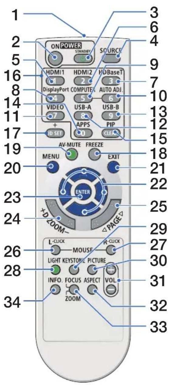
33. FOCUS/ZOOM Button
(This button does not work in this projector.)
34. INFO. Button
Displays the information screen. ( → page 70)
Battery Installation
-
Press firmly and slide the battery cover off.
-
Install AAA alkaline batteries. Ensure that you have the batteries' polarity (+/-) aligned correctly.
-
Slip the cover back over the batteries until it snaps into place.
NOTE:
- Do not mix different types of batteries or new and old batteries.
- When replacing the batteries, purchase 2 of the same type of AAA alkaline batteries.


Remote Control Precautions
- Handle the remote control carefully.
- If the remote control gets wet, wipe it dry immediately.
- Avoid excessive heat and humidity.
- Do not short, heat, or take apart batteries.
- Do not throw batteries into fire.
- If you will not be using the remote control for a long time, remove the batteries.
- Ensure that you have the batteries' polarity (+/−) aligned correctly.
- Do not use new and old batteries together, or use different types of batteries together.
- Dispose of used batteries according to your local regulations.
Operating Range for Wireless Remote Control

- The infrared signal operates by line-of-sight up to a distance of about 23 feet/7 m and within a 60-degree angle of the remote sensor on the projector cabinet.
- The projector will not respond if there are objects between the remote control and the sensor, or if strong light falls on the sensor. Weak batteries will also prevent the remote control from properly operating the projector.
2. Projecting an Image (Basic Operation)
This section describes how to turn on the projector and to project a picture onto the screen.
2-1. Flow of Projecting an Image
Step 1
- Connecting your computer / Connecting the power cord (→ page 18)

Step 2
- Turning on the projector (→ page 20)

Step 3
- Selecting a source (→ page 22)

Step 4
- Adjusting the picture size and position (→ page 23)
- Correcting keystone distortion (→ page 29)

Step 5
- Adjusting the unit's volume (→ page 32)

Step 6
- Making a presentation

Step 7
- Turning off the projector (→ page 33)

Step 8
- When Moving the Projector (→ page 34)
2-2. Connecting Your Computer/Connecting the Power Cord
1. Connect your computer to the projector.
This section will show you a basic connection to a computer. For information about other connections, see "6. Making Connections" on page 71.
Connect a commercially available HDMI cable between the computer's HDMI output connector and the projector's HDMI 1 or HDMI 2 connector.
2. Connect the supplied power cord to the projector.
First connect the supplied power cord's three-pin plug to the AC IN terminal of the projector, and then connect another plug of the supplied power cord directly in the wall outlet. Do not use any plug converter.

CAUTION:
- This equipment is designed to be used in the condition of the power cord connected to earth. If the power cord is not connected to the earth, it may cause electric shock. Please make sure the power cord is connected to the wall outlet directly and earthed properly. Do not use a 2-core plug converter adapter.
- Be sure to connect the projector and the computer (signal source) to the same earth point. If the projector and the computer (signal source) will be connected to different earth points, fluctuations in the earth potential may cause fire or smoke.
When the power cord is connected, the POWER indicator of this projector flashes orange and the unit goes into the standby mode. (In the state, [STANDBY MODE] is [NORMAL].)

a: HDMI cable (not supplied) / b: Power cord (supplied)
- Use a Premium High Speed HDMI Cable.

CAUTION:
Parts of the projector may become temporarily heated if the projector is turned off with the POWER button. Be careful to handle the projector.
2-3. Turning on the Projector

WARNING
The projector produces a strong light. When turning on the power, make sure no one within projection range is looking at the lens.
1. Remove the lens cap.
With the lens cap's stopper pressed up, pull forward and off.

Stopper
2. Press the (POWER) button on the projector cabinet or the POWER ON button on the remote control.
The POWER indicator lights blue and the image is projected on the screen.
- If no signal is being input, a blue screen is displayed. (the projector's factory default)
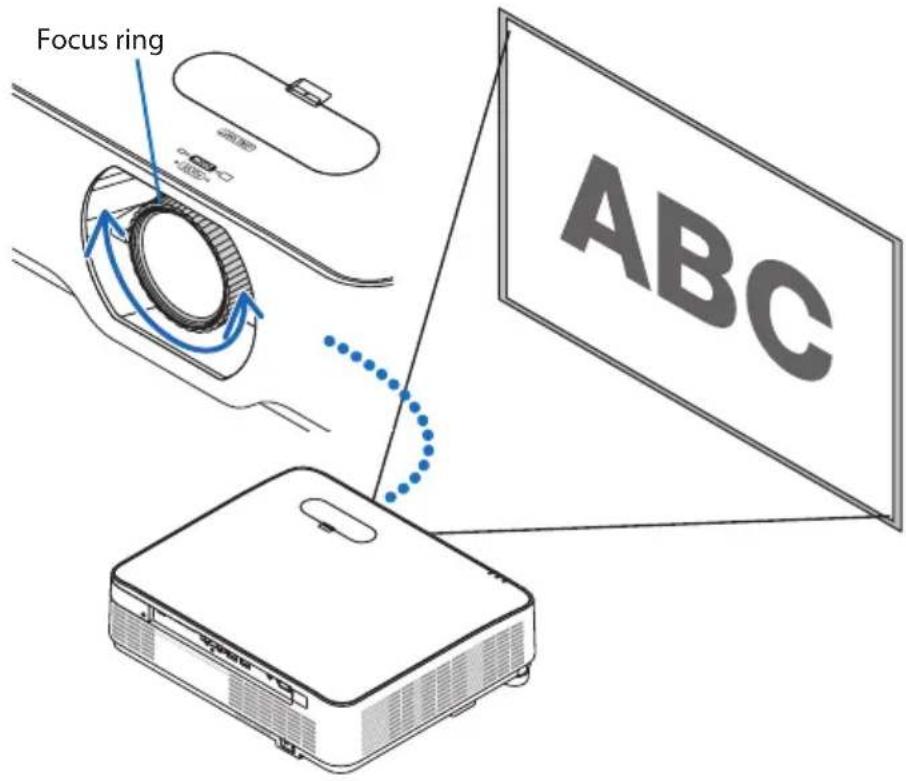
- If the image is blurry, rotate the focus ring to adjust the screen focus. (→ page 26)
NOTE:
- In the following cases, the power will not turn on even if you press the button.
- If the internal temperature is abnormally high, the device will not turn on to protect the equipment. Please wait for a while (until the internal temperature lowers) before turning on the power.
- If the status indicator lights up orange when the button is pressed, the control panel is locked. Unlock the control panel. (→ page 54)
Projector unit Remote control


TIP:
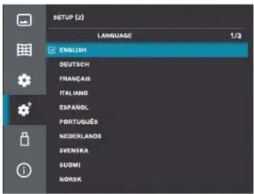
To select a menu language, follow these steps:
1. Press the MENU button on the remote control or the main unit's control panel.
The on-screen menu is displayed.
2. Use the ▲/▼ buttons to move the cursor to the [SETUP(2)] icon, then press the ENTER button or the ▶ button.
The [SETUP(2)] menu is displayed.
3. Check that the cursor is set to [LANGUAGE], then press the ENTER button or the ▶ button.
The list of display languages is displayed.
4. Use the ▲ or ▼ button to select one of the 25 languages from the menu.
5. Press the ENTER button to execute the selection.
After this has been done, you can proceed to the menu operation.



2-4. Selecting a Source
Selecting by pressing the input selector button
1. Turn on the power of the computer or DVD player connected to the projector.
To project the picture from a DVD player, etc., perform the playback (PLAY) operation.
2. Press the INPUT (input selector) button.
The input terminal screen is displayed.
Projector unit Remote control


3. Use the ▲/▼ buttons to move the cursor to the terminal whose picture you want to project, then press the ENTER button.

Selecting by pressing the HDMI1 or HDMI2 button on the remote control
1. Turn on the power of the computer or DVD player connected to the projector.
To project the picture from a DVD player, etc., perform the playback (PLAY) operation.
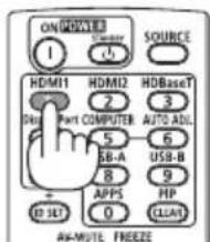
2. Press the HDMI1 or HDMI2 button on the remote control.
TIP:
- If no signal is being input, a blue screen is displayed. (this projector's factory defaults) For DVD players, etc., perform the playback (PLAY) operation.
2-5. Adjusting the Picture Size and Position
Use the lens shift dial, the adjustable tilt foot lever, the zoom lever and the focus ring to adjust the picture size and position.
In this chapter drawings and cables are omitted for clarity.

Finely adjusting the size of an image [Zoom lever] (→ page 27)

Adjusting the projected image's height and horizontal tilt [Tilt foot] (→ page 28)

Correcting the keystone distortion [Keystone] ( → page 29)


Adjusting the vertical position of a projected image (Lens shift)

CAUTION
Perform the adjustment from behind or from the side of the projector. Adjusting from the front could expose your eyes to strong light which could injure them.
1. Open the lens shift cover.
Open with the cover's stopper pushed forward.
• The lens shift cover cannot be removed.

2. Turn the lens shift dials clockwise or counterclockwise.
Vertical dial
Turn this clockwise or counterclockwise to adjust the projection position in the vertical direction. Horizontal dial
Turn this clockwise or counterclockwise to adjust the projection position in the horizontal direction.

NOTE:
- The dials can be turned more than one full turn, but the projection position cannot be moved more than the range indicated on the following page. Do not force to turn the dials. Doing so may damage the dials.
- If the lens is shifted to the maximum in the diagonal direction, the edges of the screen will be dark or shaded.
- The vertical shift adjustment must be finished with an image shifted upward. If you finish the vertical shift adjustment with an image shifted down, the zoom/focus adjustments or strong shaking may cause a projected image to slightly shift down.
3. Close the lens shift cover.
Insert the cover's 2 (two) hooks into the grooves in the projector, then close the cover.

TIP:
- The diagram below shows the lens shift adjustment range ([ORIENTATION]: [DESKTOP FRONT]).
- For the lens shift adjustment range regarding the [CEILING FRONT] projection, see page 90.
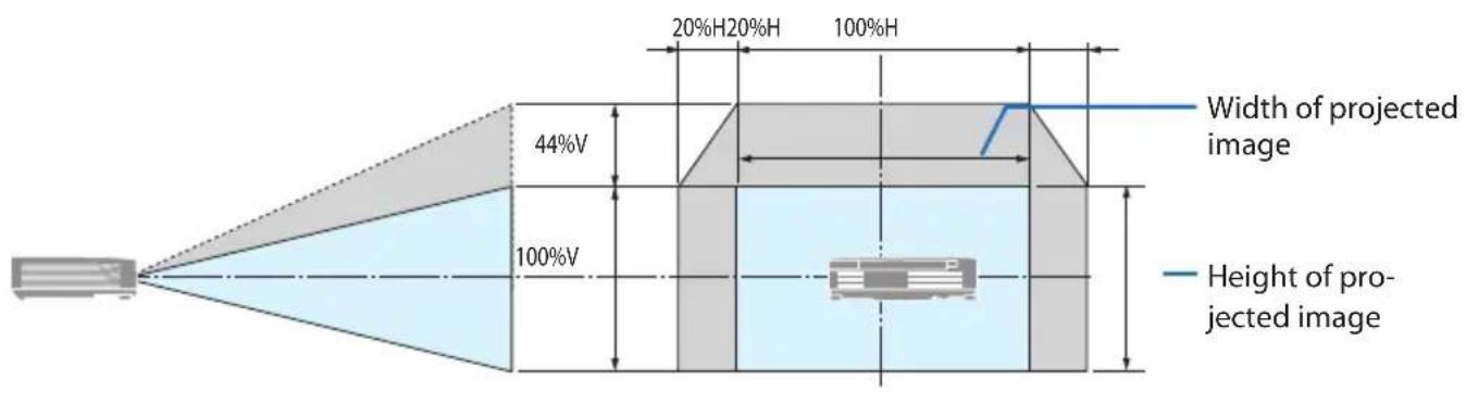
Description of symbols: V indicates vertical (height of the projected image), H indicates horizontal (width of the projected image).
Focus
Use the focus ring to obtain the best focus.
NOTE:
- Recommend to perform the focus adjustment after leaving the projector under the state the TEST PATTERN has been projected for over 30 minutes.
Please refer to page 65 about the TEST PATTERN.
Zoom
Turn the zoom lever clockwise and counterclockwise.
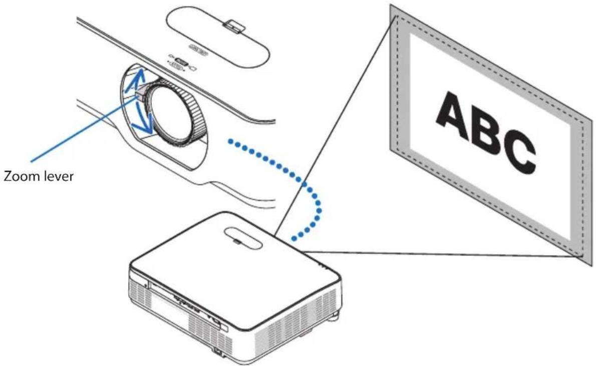
Adjusting the tilt (Tilt foot)
Adjusting the left and right tilt.
1. Turn the left and right tilt feet to adjust.
The tilt feet lengthen and shorten when turned. The height of the projected image is adjusted by turning the left and right tilt feet.
If the projected image is tilted, turn one of the tilt feet to adjust the image so that it is level.
- If the projected image is distorted, see "2-6. Adjusting for Trapezoidal Distortion (Keystone Correction)" (→ page 29).
- The tilt feet can be lengthened by a maximum of 15 mm/0.6".
- The tilt feet can be used to tilt the projector by a maximum of 2° .


NOTE:
- Do not lengthen the tilt feet any more than 15 mm/0.6". Doing so will make the tilt feet's mount section unstable and could cause the tilt feet to come off the projector.
- Do not use the tilt feet for any purpose other than adjusting the projector's projection angle.
Handling the tilt feet improperly, such as carrying the projector by grasping the tilt feet or hooking it onto a wall using the tilt feet, could damage the projector.
2-6. Adjusting for Trapezoidal Distortion (Keystone Correction)
Trapezoidal distortion of the projected image can be adjusted using the geometric correction function. This section describes the procedure for the "Horizontal/Vertical Keystone Correction" function.
About the types of geometric correction functions on this projector
This projector has the five types of geometric correction functions described below.
- For details on each correction function, refer to page 58.
- The geometric corrected state is retained even after the projector's power is turned off. To reverse geometric correction, perform the resetting procedure.
| H/V KEYSTONE Use the ▲▼◀▶ buttons to adjust for horizontal and vertical trapezoidal distortion. | |
| CORNERSTONE Adjust the trapezoidal distortion for the four corners of the projected image using the ▲▼◀▶ buttons. | |
| VERTICAL CORNER Use the ▲▼◀▶ buttons to adjust the trapezoidal distortion for a total of six points, consisting of the four corners of the projected image plus two points in the center of the upper and lower edges. | |
| PINCUSHION Adjust the curved distortion when projecting images onto a curved surface. | |
| GRID IMAGE TUNE Select multiple adjustment points displayed on the projected image to adjust for distortion. | |
| RESET This restores the adjusted image to its original state. |
Performing Horizontal/Vertical Keystone Correction
1. Press the ▼ (button on the main unit's control panel.
The [GEOMETRIC CORRECTION] menu is displayed.
- When operating from the remote control, press the KEYSTONE button.

Projector unit Remote control

2. Use the ▲/▼ buttons to move the cursor to [H/V KEYSTONE], then press the ENTER button.
The [H/V KEYSTONE] screen appears at the center of the projected image.
3. While the [H/V KEYSTONE] screen is displayed, use the ◀/▶ buttons to adjust the left/right tilt of the projected image.
- The triangular mark on the [H/V KEY-STONE] screen in the adjusted direction turns blue. A white triangular mark indicates that no adjustment has been made.
H/V KEYSTONE

- If the [H/V KEYSTONE] screen disappears, press the ▼ button (or the KEYSTONE button on the remote control) on the unit's control panel again, select [H/V KEYSTONE], and press the ENTER button.
4. While the [H/V KEYSTONE] screen is displayed, use the ▲/▼ buttons to adjust the trapezoidal distortion in the vertical direction.
H/V KEYSTONE

Screen frame Projected image


5. Repeat steps 3 and 4 to adjust the trapezoidal distortion of the projected image.

TIP:
- When the upper limit of horizontal/vertical keystone correction is reached, the triangular mark disappears.
- The adjustable range varies depending on the input signal source.
- When using the viewer (USB-A), the geometric correction menu cannot be displayed even by pressing the ▼ button on the main unit's control panel.
2-7. Adjusting the unit's volume
Adjust the volume of the projector's built-in speaker and the volume of the audio signal output from the audio output terminal.
Adjusting with the operation buttons on the projector
1. When the on-screen menu is not displayed, press the ◀ (☐) / ▶ (☐) buttons.
The volume adjustment bar is displayed.
| side | The volume increases. |
| side | The volume decreases. |
- When the volume adjustment bar is displayed, the sound can be temporarily muted using the ▲/▼ buttons.
To turn the sound back on, use the ◀/▶ buttons after the volume adjustment bar has turned off.


NOTE:
- The volume cannot be adjusted using the ◀/▶ buttons when the on-screen menu is displayed and the picture is zoomed with the D-ZOOM (+) button.
Adjusting using the remote control
1. Press the remote control's VOL. +/- buttons.
The volume adjustment bar is displayed.
| + side The volume increases. |
| - side The volume decreases. |
- When the volume adjustment bar is displayed, the sound can be temporarily muted using the ▲/▼ buttons.
To turn the sound back on, use the Volume +/- buttons after the volume adjustment bar has turned off.
- When the volume adjustment bar is displayed, the volume can also be adjusted using the ◀/▶ buttons.


2-8. Turning off the Projector
To turn off the projector:
- First, press the ⏻ (POWER) button on the projector cabinet or the STANDBY button on the remote control.
The confirmation message will be displayed.
![POWER OFF ? YES NO CARBON SAVING-SESSION 0.0000 [g-CO2]](/content/2026/08/1618187/images/12f9b96414af58972fb87dc325c631c0c4f0af84ac3f5449ace85ad3ff3dc03a.jpg)
Projector unit Remote control


- Secondly, press the ⓄPOWER) or the STANDBY button again.
When the light source turns off, the power turns off too (standby mode).
When the projector goes into the standby mode, the POWER indicator of the unit flashes orange. (In the state, [STANDBY MODE] is [NORMAL].)
- Mount the lens cap.
Insert the cap's 2 (two) hooks into the grooves of the projector, then press at the bottom of the lens cap. The stopper is secured to the projector.


CAUTION:
Parts of the projector may become temporarily heated if the projector is turned off with the POWER button.
Be careful to handle the projector.
NOTE:
- Do not unplug the power cord from the projector or from the power outlet while an image is being projected. Doing so could deteriorate the projector's AC IN terminal or the power plug's contact. To turn off the AC power while an image is being projected, use the breaker, etc.
- Do not disconnect the AC power supply to the projector within 10 seconds of making adjustment or setting changes and closing the menu. Doing so can cause loss of adjustments and settings.
TIP:
- If you are using the projector with the light mode set to [SILENT] or [LONG LIFE], a number other than 0 will be displayed for "CARBON SAVINGS-SESSION" in the power-off confirmation message.
2-9. When Moving the Projector
Preparation: Make sure that the projector is turned off.
- Unplug the power cord from the wall outlet.
- Unplug the power cord from the projector.
- Disconnect any other cables.
- Remove the USB memory if it is inserted into the projector.
- Before moving the projector, screw in the tilt foot if they have been lengthened.
3. Convenient Features
3-1. Muting the picture and sound (AV-MUTE)
1. Press the AV-MUTE button on the remote control.
The picture being projected and the sound being output from the built-in speaker and audio output terminals are temporarily turned off.
- Press the AV-MUTE button again to turn the picture and sound back on.

TIP:
- The sound from the audio output terminal (mini stereo) can also be turned off.
• The picture turns off, but not the menu.
3-2. Freezing a movie (still image)
1. Press the FREEZE button on the remote control.
When the picture of a DVD player is being projected, the movie is frozen and a still image is displayed.

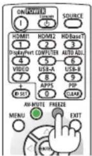
- Press the FREEZE button again to return to the movie.
NOTE:
- This function cannot be used when the USB-A input terminal is selected.
TIP:
- When the still image mode is set, the picture being projected at that time is stored in the projector's memory and the picture (still image) stored in the memory is projected. Playback on the DVD player, etc., proceeds even while the still image is displayed.
3-3. Zooming part of the picture (Partial Zoom)
1. Press the D-ZOOM (+) button on the remote control.
The picture is zoomed each time the button is pressed.
- The picture can be zoomed to a maximum of 4 times the original size.

2. Press the ▼▲◀▶ buttons.
The area of the picture that is zoomed moves.

3. Press the D-ZOOM (-) button.
The picture is reduced each time the button is pressed.
- Once returned to the original size, the picture cannot be reduced any further.
NOTE:
- With some signals, it may not be possible to zoom up to 4 times the original size.
- This function cannot be used when the USB-A input terminal is selected.
- This cannot be used when displaying the projector's built-in test pattern.
TIP:
• Picture enlargement and reduction is centered at the middle of the screen.
- Partial zooming is canceled when the ASPECT button on the remote control is pressed or when [ASPECT] is selected under [DISPLAY] in the on-screen menu and the aspect rate is changed.
3-4. Adjusting the luminance (brightness) (Light mode)
Three [LIGHT MODE] options can be selected according to the purpose of use. You can also adjust output power and change luminance (brightness).
| LIGHT MODE | Description |
| NORMAL Standard mode.You can adjust the output from 50 to 100% using [LIGHT ADJUST]. | |
| SILENT This mode prioritizes reducing operating noise.You can adjust the output from 50 to 90% using [LIGHT ADJUST]. | |
| LONG LIFE This mode prioritizes prolonging the life of the optical components.You can adjust the output from 50 to 80% using [LIGHT ADJUST]. | |
Change [LIGHT MODE]
1. Press the MENU button.
The on-screen menu is displayed.

2. Use the ▲/▼ buttons to move the cursor to the [SETUP(1)] icon, then press the ENTER button or the ▶ button.
The [SETUP(1)] menu is displayed.

- Use the ▲/▼ buttons to move the cursor to [LIGHT MODE]. Press the ▲/▼ buttons to move the cursor to [LIGHT MODE], then press either the ENTER button or the ▶ button.
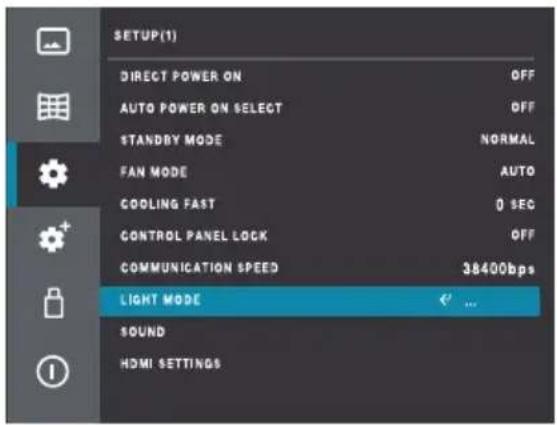
- Check that the cursor is set to [LIGHT MODE], then press the ENTER button.
“◇” is displayed at the center of the cursor.
- Use the ▲/▼ buttons to display the desired mode ([NORMAL] → [SILENT] → [LONG LIFE]), then press the ENTER button.

Perform [LIGHT ADJUST]
- Move the cursor to the [LIGHT ADJUST] and press the ENTER button.
“⇐” is displayed at the center of the cursor.
- Press the ▲/▼ buttons to adjust, then press the ENTER button.
TIP:
- You can quickly switch the light mode by pressing the LIGHT button on the remote control.
When you press the LIGHT button on the remote control, the currently set light mode is displayed in the upper left corner of the screen. After this, the light mode switches in the order [NORMAL] → [SILENT] → [LONG LIFE] each time the LIGHT button is pressed.
Note that the [LIGHT ADJUST] and [CONSTANT BRIGHTNESS] settings cannot be changed with this operation.

4. Using the Viewer (USB-A)
4-1. What you can do with the Viewer
The viewer has the following features:
- Images on a commercially available USB flash drive can be projected from this unit by inserting a USB flash drive with images stored on it into the USB port (Type A). Thanks to this, you can make presentations without using a computer.
- The types of images that can be projected by the viewer are JPEG, PNG, BMP, GIF, and TIFF.
- When projecting multiple images in succession (playing a slideshow), the following settings can be made:
| EFFECT This sets the direction for switching slides (right or down). | |
| SORT ORDER This sets the order for switching slides (by name, by time, by size or by extension). | |
| ROTATE This sets the direction of rotation of the image (90, 180 or 270 degrees). | |
| BEST FIT This sets the image's display size relative to the screen. | |
| REPEAT This sets the action performed after the last slide is displayed. |
NOTE:
- The remote control's D-ZOOM and FREEZE buttons cannot be used on the viewer screen.
-
About USB flash drives
-
Format USB flash drives to be used with the projector's viewer function in FAT32 format.
- This unit cannot recognize USB flash drives in NTFS format.
- If the USB memory inserted into the projector is not recognized, check its format.
- For formatting instructions, refer to the instruction manual or help file for your Windows operating system.
- We do not guarantee that all commercially available USB flash drives will operate with the projector's USB port.
- Check the USB flash drive for viruses as necessary.
- Supported Images
The images that can be projected by the viewer are as follows:
| Extension Format | Description | |
| jpg/jpeg | Baseline encoder 24 | Maximum resolution: 10000 x 10000 |
| Progressive RGB 24-bit | Maximum resolution: Panel resolution | |
| bmp | 1-, 4- and 8-bit palette base | Maximum resolution: 1280 x 800 |
| RGB24, 32-bit | ||
| png | 24- and 48-bit, true color | |
| gif | 1-, 4- and 8-bit palette base | |
| tiff | ||
4-2. Projecting images stored on USB flash drives (basic operation)
This section explains the basic operations of the viewer. Please see page 69 for the viewer's option menu.
- Turn on the projector's power.
- Insert the USB flash drive into the projector's USB port (USB-A).

3. Press the INPUT button.
The input terminal screen is displayed.
- When operating from the remote control, press the USB-A button.
4. Use the ▼/▲ buttons to select [USB-A], then press the ENTER button.
The screen switches to the viewer screen.
- To exit the viewer, press the input selector button and select a terminal other than [USB-A].
5. Press the ENTER button on the viewer screen.
The icons of the folders and images stored on the USB flash drive are displayed.
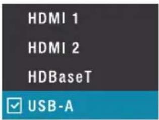

- Press the MENU button, then use the ▼/▲ buttons to move the cursor to the USB-A menu icon.
The USB-A menu is displayed.
- Make the necessary settings for the [EFFECT], [SORT ORDER], [ROTATE], [BEST FIT] and [REPEAT] menu items.
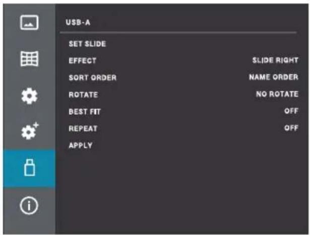
- Set the cursor to the [APPLY] menu item, then press the ENTER button.
The settings made in step 7 are applied.
- Set the cursor to the [SET SLIDE] menu item, then press the ENTER button.
Slideshow playback starts.
• To end slideshow playback, press the EXIT button.
5. Using On-Screen Menu
5-1. Basic Operations of the On-Screen Menu
The on-screen menu can be displayed to adjust the sharpness of the projected picture, to switch the unit's operation mode, etc. Hereafter, "on-screen menu" is abbreviated as "menu".
5-1-1. Structure of the on-screen menu screen
To display the menu, press the MENU button on the projector unit or the remote control. To close the menu, press the EXIT button or the MENU button.
This section explains how to view and operate the menu.
Preparation: Turn on the projector's and project a picture onto the screen.
1. Press the MENU button.
- Pressing the EXIT button or MENU button will close the menu.
- You can change the position in which the menu is displayed on the screen. (Menu Position → page 52)
2. Press the ▼/▲ buttons.
- The cursor moves between the main menu icons ([PICTURE] ⇔ [IMAGE OPTIONS] ⇔ [SETUP(1)] ⇔ [SETUP(2)] ⇔ [USB-A] ⇔ [INFORMATION]).
- When the main menu icon changes, the submenu also changes.
| Icon Main menu name | |
| PICTURE | |
| IMAGE OPTIONS | |
| SETUP (1) | |
| SETUP (2) | |
| USB-A (Viewer) | |
| INFORMATION | |
3. With the cursor set to a main menu icon, press ▶ or the ENTER button.
The cursor moves to the submenu.
- To return from a submenu to the main menu icon, press ◀ or the EXIT button.
- Press the MENU button to close the menu.
4. Use the ▼/▲ buttons to move the cursor to the desired submenu item.
The marks and item names displayed on the right edge of the submenu items indicate key operations.


Explanation of a menu screen example
-
Main menu icon
-
Submenu
-
Cursor
-
When an item name is displayed, press the ENTER button, then use the ▼/▲ buttons to cycle through the options. Press the ENTER button to confirm the option.
-
When a number is displayed, press the ENTER button, then use the ▼/▲ buttons to increase or decrease the value. Press the ENTER button to confirm the value.
-
When (⇐) is displayed, pressing the ENTER button displays the next lower level of the menu.
5-1-2. Changing numbers
As an example of operation, the following describes the procedure for changing the contrast value.
- Press the MENU button to display the on-screen menu.

- Press the ▶ or ENTER button.
The cursor moves to the [PICTURE] submenu.

- Use the ▼/▲ buttons to select [CONTRAST], then press the ENTER button.
is displayed at the center of the cursor.
- Use the ▼ / ▲ buttons to increase or decrease the value.

- Press the ENTER button.
The value is set, and the “◇” in the center of the cursor disappears.
5-1-3. Confirmation message
A confirmation message is displayed in certain cases, for example when resetting adjusted values to the factory defaults.
Use the ◀/▶ buttons to move the cursor to [YES] or [NO], then press the ENTER button.

5-2. On-screen menu list
[ ] indicates the factory default value for each item.
| Main menu Sub-menu/Setting Value (See page) | |||
| PICTURE PICTURE MANAGEMENT | NAGE-MENT | HIGH-BRIGHT, PRESENTATION, VIDEO, GRAPHIC, BLACKBOARD(GREEN), USER 48 | |
| DYNAMIC CONTRAST | OFF, MODE 1, MODE 2 | ||
| CONTRAST | 0 – 63 (32) | ||
| BRIGHTNESS | 0 – 63 (32) | ||
| COLOR TEMPERATURE | WARM, STANDARD, COOL, USER 49 | ||
| RED | 0 – 63 (32) | ||
| GREEN | 0 – 63 (32) | ||
| BLUE | 0 – 63 (32) | ||
| SHARPNESS | 0 – 15 (8) | ||
| IMAGE OPTIONS ASPECT RATIO | AUTO, WIDE, FULL, 4:3 50 | ||
| ORIENTATION DESKTOP FRONT, DESKTOP REAR, AUTO CEILING FRONT, AUTO CEILING REAR, CEILING FRONT, CEILING REAR | |||
| MENU POSITION TOP-LEFT, TOP-RIGHT, CENTER, BOTTOM-LEFT, BOTTOM-RIGHT 52 | |||
| BACKGROUND BLUE, BLACK, LOGO | |||
| SETUP (1) DIRECT POWER ON | OFF, ON 53 | ||
| AUTO POWER ON SELECT OFF, HDMI1, HDMI2 | |||
| STANDBY MODE NORMAL, NETWORK STANDBY, SLEEP | |||
| FAN MODE AUTO, HIGH ALTITUDE 54 | |||
| COOLING FAST 0 SEC, 30 SEC, 60 SEC | |||
| CONTROL PANEL LOCK OFF, ON | |||
| COMMUNICATION SPEED 4800bps, 9600bps, 19200bps, 38400bps 55 | |||
| LIGHT MODE LIGHT MODE NORMAL, SILENT, LONG LIFE | |||
| LIGHT ADJUST 50% – 100% | |||
| CONSTANT BRIGHT-NESS OFF, ON | |||
| SOUND VOLUME 0 – 25 (12) | 56 | ||
| MUTE OFF, ON | |||
| HDMI SETTINGS VIDEO LEVEL AUTO, NORMAL, ENHANCED | |||
| Main menu Sub-menu/Setting Value (See page) | ||||
| SETUP (2) LANGUAGE | English, 日本語, 中文, 中文繁體, DEUTSCH, FRANÇAIS, ITALIANO, ESPAÑOL, PORTUGUÉS, NEDERLANDS, SVENSKA, SUOMI, NORSK, DANSK, POLSKI, ČESTINA, MAGYAR, PYCCKIЙ, TÜRKÇE, اعربية, TIËNG VIËT, 한국어, ١١١٢, BAHASA INDONESIA, ROMÂNÄ | 57 | ||
| AUTO SETUP INPUT SEARCH | OFF, ON | |||
| AUTO KEYSTONE | OFF, ON | |||
| GEOMETRIC COR-RECTION | CORRECTION | STORE, RESET 58 | ||
| H/V KEYSTONE 59 | ||||
| CORNERSTONE | ||||
| VERTICAL CORNER | ||||
| PINCUSHION PINCUSHION X/Y GAIN , 60 | ||||
| GRID IMAGE TUNE 62 | ||||
| RESET | ||||
| START-UP LOCK PIN CODE LOCK | OFF, ON 63 | |||
| PIN CODE CHANGE 64 | ||||
| POWER MANAGEMENT | READY, SHUT DOWN, OFF | |||
| TIMER | 1 - 30 (5) | 65 | ||
| READY COUNT-DOWN | 0 - 30 (5) | |||
| TEST PATTERN | OFF, GRAYSCALE (1-4), COLOR BAR, RED, GREEN, BLUE, CROSS HATCH, WHITE, BLACK, RASTER GRAY, FOCUS | |||
| NETWORK SETUP | NETWORK SETTING | PROFILE (DISABLE, ENABLE) | ||
| DHCP (OFF, ON) | 66 | |||
| IP ADDRESS | ||||
| SUBNET MASK | ||||
| GATEWAY | ||||
| DNS | ||||
| NETWORK INFORMATION | ||||
| MAC ADDRESS | ||||
| IP ADDRESS | ||||
| NETWORK SERVICE | HTTP SERVER | OFF, ON | ||
| CONTROL ID | CONTROL ID | OFF, ON 67 | ||
| CONTROL ID NUMBER | 1-254 (1) | |||
| RESTORE FACTORY SETTINGS | 68 | |||
| USB-A | SET SLIDE | 69 | ||
| EFFECT | SLIDE DOWN, SLIDE RIGHT | |||
| SORT ORDER | EXTEND ORDER, NAME ORDER, TIMER ORDER, SIZE ORDER | |||
| ROTATE | NO ROTATE, 270 DEGREES, 180 DEGREES, 90 DEGREES | |||
| BEST FIT | ON/OFF | |||
| REPEAT | ON/OFF | |||
| APPLY | ||||
| INFORMATION INPUT | 70 | |||
| HORIZONTAL FREQUENCY | ||||
| VERTICAL FREQUENCY | ||||
| LIGHT HOURS USED | ||||
| MODEL NAME | ||||
| SERIAL NUMBER | ||||
| FIRMWARE VERSION | ||||
| SUBCPU | ||||
5-3. PICTURE
5-3-1. PICTURE MANAGEMENT
Select the optimal setting for the projected image.
| HIGH-BRIGHT Projects images at maximum brightness. Use this setting in bright locations. | |
| PRESENTATION Makes images brightly vivid. Use this setting when projecting content via computer signals. | |
| VIDEO Makes images naturally vivid. Use this setting when projecting content from televisions or general image sources. | |
| GRAPHIC Enables natural reproduction with high color intensity. Use this setting when projecting photographs, pictures, signage, or other such content in dark spaces. | |
| BLACKBOARD(GREEN) This mode is suitable for projecting onto a black or green board. | |
| USER | If the CONTRAST, BRIGHTNESS, COLOR TEMPERATURE, RED, GREEN, BLUE, or SHARPNESS color adjustments are changed, [USER] is displayed. |
5-3-2. DYNAMIC CONTRAST
This automatically adjusts the light source output according to the video to create an image with optimal contrast.
| OFF The contrast is not optimized. |
| MODE1 The contrast is optimized prioritizing brightness. |
| MODE2 The contrast is optimized with the brightness reduced. |
NOTE:
• [DYNAMIC CONTRAST] cannot be selected in the following cases.
- When [LIGHT MODE] is set to [SILENT] or [LONG LIFE]
- When [CONSTANT BRIGHTNESS] is set to [ON]
5-3-3. CONTRAST
This makes the difference between dark and bright parts of the image clearer or softer.
5-3-4. BRIGHTNESS
This makes the picture brighter or darker.
5-3-5. COLOR TEMPERATURE
This adjusts the hue of red, green, and blue colors.
| WARM This makes the entire screen appear reddish.The color temperature is approximately 500 K lower than when set to [STANDARD]. |
| STANDARD This sets the entire screen to a medium tone.The factory default color temperature setting is approximately 7800 K. |
| COOL This makes the entire screen appear bluish.The color temperature is approximately 500 K higher than when set to [STANDARD]. |
| USER If the values for [RED], [GREEN] and [BLUE] are adjusted individually, [USER] is displayed. |
TIP:
- Color temperature varies depending on the settings of [PICTURE MANAGEMENT] and [LIGHT MODE].
5-3-6. RED/GREEN/BLUE
These individually adjust the red, green and blue hues of the entire screen.
5-3-7. SHARPNESS
This makes the picture crisper or softer.
5-4. IMAGE OPTIONS
5-4-1. ASPECT RATIO
Select the screen's aspect ratio.
| AUTO The picture | is projected at maximum size without changing the aspect ratio of the input signal. |
| WIDE The picture | is projected with a 16:9 aspect ratio. |
| FULL The picture | is projected to the maximum extent. |
| 4:3 The picture is | projected with a 4:3 aspect ratio. |
5-4-2. ORIENTATION
Select according to the installation conditions of the projector and screen.
 WARNING WARNING | Consult your dealer for installing the projector on the ceiling. Special skills are required for ceiling installation.Never try to install the projector yourself in such cases. The projector could drop and cause injury. |
| DESKTOP FRONT When the projector is placed on a table and projects from in front of the screen. | |
 | |
| DESKTOP REAR When the projector is placed on a table and projects from behind the screen (using a semitransparent screen). | |
 | |
| AUTO CEILING FRONT | When projecting from the front of the screen, after the built-in angle sensor automatically detects the projector's angle, switch to [DESKTOP FRONT] or [CEILING FRONT]. Select this item if you are projecting from the front of the screen. |
| AUTO CEILING REAR | When projecting from behind the screen, after the built-in angle sensor automatically detects the projector's angle, switch to [DESKTOP REAR] or [CEILING REAR]. Select this item if you are projecting from behind the screen. |
| CEILING FRONT When | installing the projector high on the ceiling in front of the screen using a ceiling mount fitting (sold separately). |
 | |
| CEILING REAR When | installing the projector high on the ceiling behind the screen using a ceiling mount fitting (sold separately) (using a semitransparent screen). |
 | |
TIP:
- About the Angle Sensor
The detectable angle range of the projector's built-in angle sensor is as shown in the figure below.
![If you select [AUTO CEILING FRONT] or [AUTO CEILING REAR] for the orientation, the projector automatically determines the image will be projected from the front. Approx. 120° Approx. 60° Approx. 120° Approx. 60° If you select [AUTO CEILING FRONT] or [AUTO CEILING REAR] for the orientation, the proje…](/content/2026/08/1618187/images/037f12837fc0e28c6436a6d47c861125f360943a334f3a1081b262d35786e8c1.jpg)
If you select [AUTO CEILING FRONT] or [AUTO CEILING REAR] for the orientation, the projector automatically determines the image will be projected from the ceiling.
5-4-3. MENU POSITION
This changes the on-screen menu's display position.
| TOP-LEFT The menu | is displayed in the upper left corner of the screen. |
| TOP-RIGHT The menu | is displayed in the upper right corner of the screen. |
| CENTER The menu is | displayed in the center of the screen. |
| BOTTOM-LEFT The menu | is displayed in the lower left corner of the screen. |
| BOTTOM-RIGHT The menu | is displayed in the lower right corner of the screen. |
5-4-4. BACKGROUND
This selects the color of the background when there is no input signal.
| BLUE The entire projection area is displayed in blue. |
| BLACK The entire projection area is displayed in black. |
| LOGO The registered background is displayed over the entire projection area.BLACK (no logo image) is displayed when shipped from the factory. |
NOTE:
- This function is disabled when USB-A is selected as the input signal.
TIP:
- To register a logo image, use the HTTP server function.
5-5. SETUP (1)
5-5-1. DIRECT POWER ON
This sets the operation when the power cord is connected to the projector or when power is supplied.
| OFF When the power cord is connected to the projector or when power is supplied, the projector is set to the standby mode. Press the power button to turn on the power. |
| ON When the power cord is connected to the projector or when power is supplied, the projector's power automatically turns on. |
NOTE:
- After turning off the power, disconnect the power cord, wait about 20 seconds, then reconnect the power cord. The projector may not operate normally if the power is turned on and off or the power cord is connected and disconnected in a short period of time.
5-5-2. AUTO POWER ON SELECT
This function automatically projects a picture when an HDMI signal is input while the unit is in the standby mode.
| OFF The Auto Power | On function will not operate. |
| HDMI1 When a signal is detected at the HDMI1 input terminal, the picture is projected. | |
| HDMI2 When a signal is detected at the HDMI2 input terminal, the picture is projected. | |
NOTE:
- If [AUTO POWER ON] is set to HDMI1 or HDMI2, [STANDBY MODE] will be grayed out and cannot be selected.
- When [AUTO POWER ON] is set to HDMI1, turn off the power while projecting the image from the HDMI 1 input terminal. Similarly, when [AUTO POWER ON] is set to HDMI2, turn off the power while projecting the image from the HDMI 2 input terminal.
5-5-3. STANDBY MODE
This selects the operation mode when the projector is in standby.
| NORMAL In this mode | , power consumption is lower than in “Network Standby” or “Sleep” mode, but the projector cannot be controlled via the LAN port when this mode is selected.To turn on the projector’s power, press the power button on the projector cabinet or remote control. |
| NETWORK STANDBY | In this mode, power consumption is higher than in [NORMAL] mode, but the unit can be turned on from standby using the “Wake on LAN” function via LAN.For details on the “Wake on LAN” function, please consult your network administrator. |
| SLEEP In this mode, | power consumption is higher than in “Network Standby” mode, but the projector’s power can be turned on using control software. |
5-5-4. FAN MODE
This sets the operation of the cooling fan to reduce the projector's internal temperature.
This changes the speed of the cooling fan according to the altitude of the location where the projector is used.
| AUTO The built-in fans automatically run at a variable speed according to the internal temperature. |
| HIGH ALTITUDE The built-in fans run at a high speed. Select this option when using the projector at altitudes approximately 5500 feet/1600 meters or higher. |
NOTE:
- Set [FAN MODE] to [HIGH ALTITUDE] when using the projector at altitudes approximately 5500 feet/1600 meters or higher.
- Using the projector at altitudes approximately 5500 feet/1600 meters or higher without setting to [HIGH ALTITUDE] can cause the projector to overheat and the protector could shut down. If this happens, wait a couple minutes and turn on the projector.
- Using the projector at altitudes approximately 5500 feet/1600 meters or higher can shorten the life of optical components such as the light module.
5-5-5. COOLING FAST
This sets the time the cooling fan runs after the projector is turned off.
The power indicator blinks green while the cooling fan is running.
Do not unplug the power cord while the cooling fan is running.
| 0 SEC The cooling fan does not run after the unit is turned off. |
| 30 SEC The cooling fan runs for 30 seconds after the projector is turned off. |
| 60 SEC The cooling fan runs for 60 seconds after the projector is turned off. |
5-5-6. CONTROL PANEL LOCK
This disables the operation buttons on the projector.
| OFF The buttons on | the projector's control panel work. |
| ON The buttons on | the projector's control panel do not work (they are locked). |
TIP:
- The remote control buttons will work even when the main unit's operation buttons are locked.
5-5-7. COMMUNICATION SPEED
This sets the data transfer speed for the RS-232C terminal. Set this according to the transfer speed of the connected device.
5-5-8. LIGHT MODE
Three [LIGHT MODE] options can be selected according to the purpose of use. You can also adjust output power and change luminance (brightness).
LIGHT MODE
| NORMAL This is the standard mode. |
| SILENT This mode prioritizes reducing operating noise. |
| LONG LIFE This mode prioritizes prolonging the life of the optical components. |
LIGHT ADJUST
The output of each [LIGHT MODE] can be adjusted in 1%.
The adjustment range will vary depending on the [LIGHT MODE] settings.
NORMAL: 50 - 100%
SILENT: 50 - 90%
LONG LIFE: 50 - 80%
CONSTANT BRIGHTNESS
| OFF [CONSTANT BR] | GHTNESS] mode will be canceled. |
| ON Maintains a constant brightness. | |
NOTE:
- When [CONSTANT BRIGHTNESS] is set to [ON], [LIGHT MODE] and [LIGHT ADJUST] cannot be selected.
TIP:
- Brightness normally decreases with use, but by selecting [CONSTANT BRIGHTNESS] mode, the projector automatically adjust the output based on the projector used time, thereby maintaining a constant brightness throughout the life of the light module. However, if output is already at its maximum, brightness will decrease with use.
5-5-9. SOUND
This adjusts the audio output from the projector.
| VOLUME | Press the ◀ button to decrease the volume, the ▶ button to increase the volume. The range is 0 to +25. |
| MUTE Sound is output | put when [OFF] is selected, and no sound is output when [ON] stops audio output. |
5-5-10. HDMI SETTINGS
Change these settings according to the output conditions of the device connected to the HDMI1 or HDMI2 input terminal.
VIDEO LEVEL
| AUTO | Full range or limited range of the HDMI signal level is detected automatically. If the range cannot be correctly detected automatically, manually switch to [NORMAL] or [ENHANCED]. |
| NORMAL Select this | when connecting a device whose HDMI signal level is set to full range. |
| ENHANCED Select this | when connecting a device whose HDMI signal level is set to limited range. |
5-6. SETUP(2)
5-6-1. LANGUAGE
This selects the language for the menu's display.
The language will revert to English if you reset the factory defaults from the on-screen menu.
5-6-2. AUTO SETUP
This turns automatic input signal search, automatic adjustment of the computer's video signals and automatic keystone correction on or off.
INPUT SEARCH
| OFF Press the input | selector button to select the input signal manually. |
| ON The input signal | is detected automatically and the image is projected. |
AUTO KEYSTONE
| OFF Perform keystone correction manually. |
| ON The projector's tilt is detected and keystone distortion of the projected picture is automatically adjusted the vertical direction. |
NOTE:
• Automatic keystone correction may not work even when [AUTO KEYSTONE] is set to [ON].
- Auto keystone correction does not work when [CEILING FRONT] or [CEILING REAR] is set at [ORIENTATION] in the on-screen menu.
- When [AUTO CEILING FRONT] or [AUTO CEILING REAR] is set at [ORIENTATION] in the on-screen menu and this unit is mounted on the ceiling, auto keystone correction will not work.
- The USB-A terminal cannot be searched when [INPUT SEARCH] is set to [ON].
5-6-3. GEOMETRIC CORRECTION
When projecting onto a tilted or curved screen, the projected image will be distorted and extend beyond the screen.
In this case, use the unit's [GEOMETRIC CORRECTION] function to adjust the projected image so that it fits within the screen.
When [GEOMETRIC CORRECTION] is selected in the on-screen menu, the geometric correction menu appears.
This projector has the five types of geometric correction functions described below.
- H/V KEYSTONE
- CORNERSTONE
- VERTICAL CORNER
- PINCUSHION
-
GRID IMAGE TUNE
-
The geometric correction status is retained even after the projector's power is turned off. To reverse geometric correction, perform the resetting procedure.
- Some of the five correction functions cannot be combined for adjustment.
If you adjust any of the adjustments, the correction functions that cannot be combined will be grayed out and will not be selectable.
If you want to switch to a correction function that cannot be combined, perform [RESET].
Combining correction functions
| H/V KEYSTONE | CORNERSTONE | VERTICAL CORNER | PINCUSHION | GRID IMAGE TUNE | |
| H/V KEYSTONE - | No No No No | ||||
| CORNERSTONE | No - No No No | ||||
| VERTICAL CORNER | No No - Yes Yes | ||||
| PINCUSHION No | No Yes - Yes | ||||
| GRID IMAGE TUNE | No No Yes | Yes - |
Yes : adjustable / No : non-adjustable
- Displaying the projector's built-in [CROSS HATCH] test pattern makes it easier to adjust. (→ page 65)
CORRECTION
| STORE The geometric correction values are retained even after the projector is turned off. |
| RESET When the projector is turned off, the geometric correction values are reset. |
H/V KEYSTONE
Use the ▲▼◀▶ buttons to adjust for horizontal and vertical trapezoidal distortion.
For operating instructions, please refer to page 29.
Pressing the ▲ button reduces the width of the top edge.  | Pressing the ▼ button reduces the width of the bottom edge.  | Pressing the ◀ button reduces the width of the left edge.  | Pressing the ▶ button reduces the width of the right edge.  |
CORNERSTONE
Adjust the trapezoidal distortion for the four corners of the projected image using the ▲▼◀▶ buttons.
Use the ▲▼◀▶ buttons to adjust the trapezoidal distortion for a total of six points, consisting of the four corners of the projected image plus two points in the center of the upper and lower edges.
UPPER LEFT CENTER 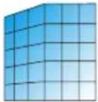 | TOP UPPER RIGHT | LOWER RIGHT |  | CENTER BUTTOM  | LOWER LEFT  |
 |  |
PINCUSHION
Adjust the curved distortion when projecting images onto a curved surface.
Curved correction is divided into 3 modes. The mode switches when the ENTER button is pressed.
![graph LR A["1. PINCUSHION X/Y GAIN"] --> B["2. PINCUSHION X OFFSET"] B --> C["3. PINCUSHION Y OFFSET"]](/content/2026/08/1618187/images/8ae974beb2a33cdda4355483ca28a0bb509323f7c804bd1ab28d8ee0b6fc0f46.jpg)
1. PINCUSHION X/Y GAIN
| Before correction Operation After correction Description | ||
 | ◀ button Expan 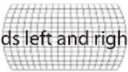 | edges horizontally. |
| ▶ button |  | |
| ▲ button |  | |
| ▼ button |  | |
2. PINCUSHION X OFFSET
| Before correction O | Operation After | correction Description | |
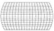 | ◀ button |  | Corrects the distortion on the left side.Expands the top and bottom of the left edge outwards while maintaining the distortion on the right side. |
| ▶ button |  | Corrects the distortion on the right side.Expands the top and bottom of the right edge outwards while maintaining the distortion on the left side. | |
| ▲ button |  | Corrects the horizontal distortion.Expands the left and right of the top section outwards, and reduces the left and right of the bottom section inwards. | |
| ▼ button |  | Corrects the horizontal distortion.Expands the left and right of the bottom section outwards, and reduces the left and right of the top section inwards. | |
 | ◀ button |  | Corrects the distortion on the left side.Expands the center of the left edge outwards while maintaining the distortion on the right side. |
| ▶ button |  | Corrects the distortion on the right side.Expands the center of the right edge outwards while maintaining the distortion on the left side. | |
| ▲ button | 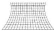 | Corrects the horizontal distortion.Expands the left and right of the top section inwards while maintaining the distortion of the bottom section. | |
| ▼ button |  | Corrects the horizontal distortion.Reduces the left and right of the bottom section inwards while maintaining the distortion of the top section. |
3. PINCUSHION Y OFFSET
| Before correction Operation After Correction Description | |||
 | ◀ button |  | Corrects the vertical distortion.Expands the top and bottom of the left edge outwards and reduces the top and bottom of the right edge inwards. |
| ▶ button |  | Corrects the vertical distortion.Expands the top and bottom of the right edge outwards and reduces the top and bottom of the left edge inwards. | |
| ▲ button |  | Corrects the distortion on the top side.Expands the left and right of the top edge upwards while maintaining the distortion on the bottom side. | |
| ▼ button |  | Corrects the distortion on the bottom side.Expands the left and right of the bottom edge downwards while maintaining the distortion on the top side. | |
 | ◀ button | 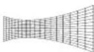 | Corrects the vertical distortion.Reduces the top and bottom of the left edgeinwards while maintaining the distortion on the right side. |
| ▶ button |  | Corrects the vertical distortion.Reduces the top and bottom of the right edgeinwards while maintaining the distortion on the left side. | |
| ▲ button |  | Corrects the distortion on the top side.Expands the center of the top edge upwardswhile maintaining the distortion on the bottom side. | |
| ▼ button |  | Corrects the distortion on the bottom side.Expands center of the bottom edge downwardswhile maintaining the distortion on the top side. | |
GRID IMAGE TUNE
Select one of the multiple adjustment points displayed on the entire projection screen and use the
▲▼◀▶ buttons to adjust the distortion.
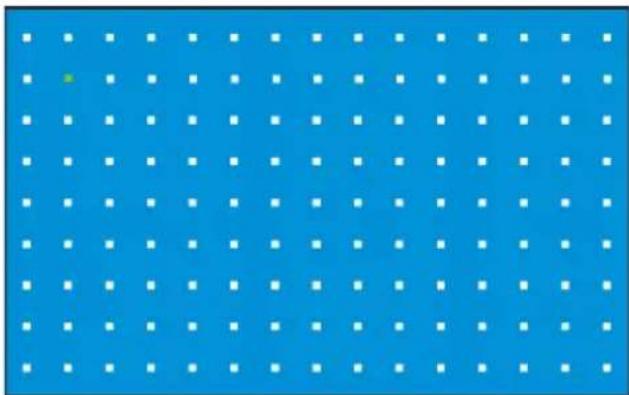
RESET
This restores the adjusted image to its original state.
NOTE:
- The maximum keystone correction range is ± 30 degrees vertically and horizontally. However, using maximum correction will reduce image quality and make focusing more difficult. Please use the minimum correction value for the projector.
- Keystone correction may affect the image's aspect ratio.
5-6-4. START-UP LOCK
You can prevent unauthorized use of the projector by setting a PIN code (a 3-digit number). If START-UP LOCK is enabled, the PIN CODE input screen will appear when the unit's power is turned on, and projection will not be possible without inputting the correct PIN code.
Important
- The PIN code is not canceled even when you reset the factory defaults from the on-screen menu. Please write down and store the PIN code you have set in a safe place so you don't forget it.
- When you enter the PIN code, pay enough attention to people around for the PIN code abuse prevention. If you have anxiety the PIN code is cheated, change the PIN code immediately.
PIN CODE LOCK
When you select [PIN CODE LOCK], the PIN code (a 3-digit number) input screen appears. Input the PIN code. The PIN code is set to "111" upon shipment from the factory.
| OFF The Pin Code Lock function cannot be used. |
| ON When the projector's power is turned on, the PIN code input screen will appear. |

How to input the PIN code
- At the PIN code input screen, press the ENTER button.
The "0" frame and the left frame of the PIN code input field turns blue.
- Press the ▶ button.
The color of the "1" frame turns blue.
- Press the ENTER button.
"1" is input into the left frame of the PIN code input field, and the frame at its right turns blue. The input "1" will change to "* " after a short while.
- Press the ENTER button.
"1" is input into the center frame of the PIN code input field, and the frame at its right turns blue.
- Press the ENTER button.
"1" is input into the right frame of the PIN code input field, and [SET] turns orange.
- Check that the cursor is set to [SET], then press the ENTER button.
The PIN code input screen disappears.
PIN CODE CHANGE
You can change the factory default PIN code ("111") to any other number.
If you select "PIN CODE CHANGE", the PIN code input screen appears. Input the current PIN code.
Next, the screen for inputting the new PIN code appears. Input the new PIN code.
TIP:
- If you forget your PIN code
- If you can display the on-screen menu, go to [SETUP(2)] → [RESTORE FACTORY SETTINGS] to reset the PIN code.
Using [RESTORE FACTORY SETTINGS] will return all settings to the factory default.
- If you cannot display the on-screen menu, contact your dealer.
5-6-5. POWER MANAGEMENT
If no signal is input for longer than the set amount of time and the projector is not operated, the projector's light source automatically turns off or the power will turn off.
Set the modes (Ready, Shut Down, and Off) and the times.
| READY | When the time set at [TIMER] below is reached, the projector switches to the Ready (standby) mode (with the light source off).When in the Ready mode, the POWER indicator is flashing green.If an input signal is detected or if a button (other than the power button) on the main unit's control panel or on the remote control is pressed while in the Ready mode, the light source turns back on. |
| SHUT DOWN | When the time set at [TIMER] below is reached, the projector's power turns off and the standby mode is set. |
| OFF The power management function is disabled. | |
TIMER
Set the time until the light source is turned off or until the projector is shut down. The time can be set from 1 to 30 minutes. The factory default setting is "5 minutes".
If the unit remains without a signal and no button is operated for 30 seconds, "NO INPUT" and the time remaining until the projector is switched to the Ready mode (light source off) or shuts down are displayed in the lower right corner of the screen.
READY COUNTDOWN
This sets the time (0 to 30 minutes) after entering the Ready mode until the projector's power turns off and the standby mode is set. The factory default setting is "5 minutes". If set to "0 minutes", the projector stays in the Ready mode.
5-6-6. TEST PATTERN
This displays several types of test patterns built into the projector.
Display a test pattern when adjusting the focus or keystone correction of the projected image.
To return from the test pattern screen to the original screen, press the MENU button, select "TEST PATTERN" again, move the cursor to [OFF], then press the ENTER button.
5-6-7. NETWORK SETUP
When controlling the projector from a computer via a network, make the network settings so that the projector can be connected.
- Before making the network settings, connect the projector and router, etc., with a LAN cable. (→ page 72)
- For instructions on changing the IP address, subnet mask, gateway and DNS, refer to page 78.
- After changing the network settings, use the ▲/▼ buttons to move the cursor to [SET], then press the ENTER button.

ENTER button


| PROFILE | Set the cursor in place then press the ENTER button. Use the ▲ / ▼ buttons to switch to “DISABLE” or “ENABLE,” then press the ENTER button. | |
| DISABLE Disables wired LAN. | ||
| ENABLE Enables wired LAN. | ||
| DHCP | Set the cursor in place then press the ENTER button. Use the ▲/▼ buttons to move the cursor to [ON] or [OFF], then press the ENTER button. | |
| OFF Manually set the IP address and subnet mask assigned by the network administrator. | ||
| ON The IP address, subnet mask and gateway are automatically as-signed by the DHCP server. | ||
| IP ADDRESS If “DHCP” was set to [OFF], set the projector’s IP address on the network to which the projector is connected. | ||
| SUBNET MASK If “DHCP” is set to [OFF], set the projector’s subnet mask on the network to which the projector is connected. | ||
| GATEWAY If “DHCP” is set to [OFF], set the projector’s default gateway on the network to which the projector is connected. | ||
| DNS | If “DHCP” was set to [OFF], set the IP address of the DNS server on the network to which the projector is connected. | |
5-6-8. NETWORK SERVICE
Set whether or not to connect to the projector's HTTP server.
HTTP SERVER
| OFF | Connection to the HTTP server is not possible. |
| ON | Connection to the HTTP server is possible. |
5-6-9. CONTROL ID
Multiple projectors can be operated individually by assigning IDs to them and switching IDs using a single remote control unit.
This function can also be used to set the same ID for multiple projectors and operate all the projectors at once with a single remote control unit.
| CONTROL ID OFF The control ID function is disabled. | |
| ON The con | control ID function is enabled. |
| CONTROL ID NUM-BER | Select a number from 1 to 254 to assign to the projector.The factory default setting is "1". |
NOTE:
- When "CONTROL ID" is set to [ON], it is not possible to operate the projector(s) from remote control units that do not support the control ID function (the operation buttons on the projector can still be used).
How to set and change IDs on the remote control
1. Turn on the projector's power.
2. Press the ID SET button on the remote control.
The control ID screen is displayed.
At this time, if the current remote control ID can operate the projector, the "Active" screen is displayed; if not, the "Inactive" screen is displayed.
If you want to operate a projector for which "Inactive" is displayed, set the remote control to the same number as the projector's control ID number set in step 3.
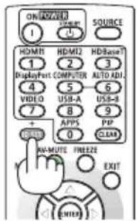
When "CONTROL ID" is set to [OFF]

When "CONTROL ID" is set to [ON], the control ID number is "1", and the remote control ID matches

When "CONTROL ID" is set to [ON], the control ID number is "1", and the remote control ID does not match

3. Press and hold the ID SET button on the remote control, then press a number button to set the remote control's ID.
For example, to change to the control ID to "3", press number 3.
To set no ID (and operate all the projectors at once), either input "000" or press the CLEAR button.
TIP:
- You can register remote control IDs from 1 to 254.

4. Release the ID SET button.
The control ID screen is displayed.
At this time, the active/inactive screen is updated with the changed remote control ID.
NOTE:
- The IDs may be cleared after a while if the remote control's battery is low or the battery is removed.
- Note that the set IDs will be cleared if any button is pressed while the remote control's battery is removed.
5-6-10. RESTORE FACTORY SETTINGS
This returns the adjusted values for all the adjustments and settings stored in the projector or for the currently displayed signal to the factory defaults.
5-7. USB-A
Display the viewer screen by following the steps in "4-2. Projecting images stored on USB flash drives (basic operation)". (→ page 40)
| SET SLIDE | The images as displayed as slides according to the [EFFECT], "SORT ORDER", "ROTATE", "BEST FIT" and "REPEAT" settings.If you change any settings, be sure to set the cursor to [APPLY] and press the ENTER button. | |
| EFFECT This sets the direction for switching slides. | ||
| SLIDE RIGHT The slides switch from left to right. | ||
| SLIDE DOWN The slides switch from top to bottom. | ||
| SORT ORDER This sets the order for switching the slides. | ||
| NAME ORDER The files or folders are sorted by name. | ||
| TIMER ORDER The files or folders are sorted by time. | ||
| SIZE ORDER The files or folders are sorted by size. | ||
| EXTEND ORDER The files or folders are sorted by extension. | ||
| ROTATE This sets the direction of rotation of the images. | ||
| NO ROTATE Rotation is disabled. | ||
| 90 DEGREE The images are rotated 90 degrees clockwise. | ||
| 180 DEGREE | The images are rotated 180 degrees clockwise. | |
| 270 DEGREE | The images are rotated 270 degrees clockwise. | |
| BEST FIT | This sets the display size of the images. | |
| OFF | Displays the image at normal pixel resolution. | |
| ON | Displays the image according to the screen aspect ratio. | |
| REPEAT | This sets the action performed after the last slide is displayed. | |
| OFF | After the last image is displayed, the image list screen reappears. | |
| ON | After the last image is displayed, the slideshow starts over from the first image. | |
| APPLY | This applies the settings for [EFFECT], [SORT ORDER], [ROTATE], [BEST FIT], and [RE-PEAT].If you change any settings, be sure to set the cursor to [APPLY] and press the ENTER button. | |
5-8. INFORMATION
This displays information about the projected signal, the projector, etc.
| INPUT This displays | the terminal name selected with the input selector. Also, when set to COMPUTER, HDMI1, or HDMI2, the signal resolution is displayed. |
| HORIZONTAL FREQUENCY | This displays the input signal's horizontal synchronizing frequency in kHz. “--- kHz” is displayed when there is no signal. |
| VERTICAL FRE-QUENCY | This displays the input signal's vertical synchronizing frequency in Hz. “--- Hz” is displayed when there is no signal. |
| LIGHT HOURS USED | This displays the light source's usage time. |
| MODEL NAME This displays the model name. | |
| SERIAL NUMBER This displays the projector's serial number. | |
| FIRMWARE VER-SION | This displays the projector's firmware version. |
| SUBCPU This displays the projector's SUBCPU firmware version. | |
6. Making Connections
NOTE:
- The connection cable is not enclosed with the projector. Please get ready a suitable cable for the connection.
For HDMI, LAN, RS-232C and AUDIO, please use a shielded signal cable.
Use of other cables and adapters may cause interference with radio and television reception.
6-1. Connecting to Computers and Video Devices
Below is an example of connections to external devices.

a: Computer, etc. / b: Blu-ray player, etc. /
c: HDMI cable (not supplied) (Use a Premium High Speed HDMI Cable.) /
d: Audio device, etc. / e: Stereo mini-plug audio cable (not supplied)
- The projector automatically detects whether the HDMI signal level is full range or limited range. If the HDMI input signal is not projected correctly, check the signal level of the device connected to the HDMI1 or HDMI2 input terminal and switch the [HDMI SETTINGS] in the on-screen menu. (→ page 56)
6-2. Connecting to a Wired LAN
When the projector is connected to a wired LAN, you can use the web browser on a computer to control the projector using the HTTP server function.
For more information, see "7. Connecting to a Network" (→ page 78).
Example of LAN connection
Example of wired LAN connection
![graph TD A["Computer"] --> B["Server"] B --> C["Switch"] C --> D["LAN"] D --> E["Computer"] C --> F["Server"] F --> G["Switch"] G --> H["LAN"] style A fill:#f9f,stroke:#333 style B fill:#ccf,stroke:#333 style C fill:#cfc,stroke:#333 style D fill:#fcc,stroke:#333 style E fill:#cff,stroke:#333 style F…](/content/2026/08/1618187/images/0fa14859012cccb6493e1d558272505169091169e717b77032e4ab549b0e2159.jpg)
a: Server / b: Hub /
c: LAN cable (not supplied)
(Use a shielded twisted pair (STP) cable of Category 5e or higher for the LAN cable.)
6-3. Connecting to a HDBaseT transmission device (sold commercially)
HDBaseT is a connection standard for home appliances that is established by the HDBaseT Alliance. Use a LAN cable sold commercially to connect the HDBaseT port of the projector (RJ-45) to a HDBaseT transmission device sold commercially.
The HDBaseT port of the projector supports HDMI signals (HDCP) from transmission devices, and serial control from external devices.
- Refer to the owner's manual accompanied with your HDBaseT transmission for connecting with your external devices.
Connection example
![graph TD A["Computer"] -->|a| B["Server"] B --> C["Switch"] C --> D["HDBaseT"] D --> E["PC"] D --> F["PC"] D --> G["PC"] D --> H["PC"] D --> I["PC"] D --> J["PC"] D --> K["PC"] D --> L["PC"] D --> M["PC"] D --> N["PC"] D --> O["PC"] D --> P["PC"] D --> Q["PC"] D --> R["PC"] D --> S["PC"] D --> T["PC…](/content/2026/08/1618187/images/74179b24f8eaddff5ae7df451f8a5b5a82326ccb8ae30c34cd23185853f24540.jpg)
a: Computer (for control use) / b: Computer (for output use) / c: Example of a transmission device / d: HDMI output video device
NOTE:
- Please use a shielded twisted pair (STP) cable of Category 5e or higher for the LAN cable (sold commercially).
- The maximum transmission distance over the LAN cable is 100 m. (the maximum distance is 70 m for a 4K signal)
- Short cable such as 0.5m is not applicable in HDBaseT Projector installations.
- Please do not use other transmission equipment between the projector and transmission equipment. The picture quality may be deteriorated as a result.
- This projector is not guaranteed to work with all HDBaseT transmission devices sold commercially.
6-4. Portrait projection (vertical orientation)
Portrait screens from a computer can be projected by installing the projector in a vertical orientation.


Precautions during installation
- Please do not install the projector in a vertical orientation on top of the floor or table on its own. The intake vent or the exhaust vent may be obstructed, resulting in the projector getting warm and the possibility of fire and malfunction occurring.
- A stand for supporting the projector needs to be made for this purpose. In this case, the stand must be designed such that the center of gravity of the projector is located well within the legs of the stand. If not, the projector may fall over and result in injury, damage and malfunction.
• Take measures to prevent the projector from falling in anticipation of a malfunction occurring in the projector or stand.
Design and manufacturing conditions for the stand
Please engage an installation service provider for the design and manufacture of the customized stand to be used for portrait projection. Please ensure that the following are complied with when designing the stand.
- When installing the projector with its exhaust vent facing downward, maintain a distance of at least 200 mm between the projector exhaust vent and the floor.
Do not obstruct the intake vent at the rear of the projector.
- Use the four screw holes on the bottom face of the projector to secure it to the stand.
Screw hole center dimension: 200 × 250 mm
Screw hole dimension on the projector: M4 with a maximum depth of 8 mm.
* Please design the stand such that the rear legs on the bottom face of the projector do not contact the stand. The tilt foot can be turned and removed.
-
Horizontal adjustment mechanism (for example, bolts and nuts in four locations)
-
Please design the stand such that it does not topple over easily.
Reference drawings
* The drawing showing the dimensional requirements is not an actual stand design drawing. (Unit: mm)
![Screw holes for 4 - M4 use 200 Notch 250 Intake vent Exhaust Vent [Side View][Front View] Horizontal adjuster Installation facing the exhaust vent downward, maintain a distance of at least 200 mm between the projector Exhaust vent and the floor.](/content/2026/08/1618187/images/92e8fe66954e7610a2cd68ad4c151a0e6741c3e960aa14aca1ada5191c10ddcb.jpg)
7. Connecting to a Network
7-1. What You Can Do by Connecting to a Network
- A web browser on a computer or tablet connected to the same network (via wireless or wired router) can be used to access the projector's HTTP server through its wired LAN connection. This allows the user to control the projector and configure network settings.
- The projector's HTTP server allows you to change the HTTP server login password, adjust images, adjust the screen, configure network settings, make the Crestron control settings, AMX settings, PJLink settings, and more.
7-2. Enabling the projector's wired LAN function
Preparation
- Connect a LAN cable to the projector. (→ page 72)
- Press the MENU button to display the on-screen menu.
- Use the ▼ / ▲ buttons to move the cursor to the [SETUP (2)] icon, then press the ▶ or ENTER button.
The cursor moves to the submenu.
- Use the ▼/▲ buttons to select [NETWORK SETTING], then press the ENTER button.
The NETWORK SETTING menu is displayed.

- Check that the cursor is set to [NETWORK SETTING], then press the ENTER button.
The wired LAN settings screen is displayed.

5. Check that the cursor is set to [PROFILE], then press the ENTER button.
The background of [DISABLE] in PROFILE changes to blue.


6. Use the ▼/▲ buttons to select [ENABLE], then press the ENTER button.
When PROFILE is set to [ENABLE], wired LAN is enabled.
- If you want to save the network settings in the projector while DHCP is [ON], proceed to step 13.
- To change to a desired IP address, proceed to step 7.
Changing the IP address
(Example: To set the projector's IP address to 192.168.1.100)

7. Use the ▼/▲ buttons to select [DHCP], then press the ENTER button.
8. Use the ▼/▲ buttons to select [OFF], then press the ENTER button.
The IP address can be changed when DHCP is turned off.

9. Use the ▼/▲ buttons to select [IP ADDRESS], then press the ENTER button.
The IP address' leftmost input field turns blue.

10. Use the ▼/▲ button to change the value, then press the ENTER button.
The next IP address input field to the right turns blue.
11. Repeat step 10 to set the IP address.
When you press the ENTER button at the right-most input field, the IP address row turns blue.
12. Use this same procedure to set [SUBNET MASK], [GATEWAY], [DNS], etc.

13. Use the ▼/▲ buttons to set the cursor to [SET], then press the ENTER button.
The network settings are saved in the projector unit.


7-3. Connecting to the projector's HTTP server
Preparation
- Configure the projector's network settings. (→ page 78)
1. Display and confirm the projector's IP address.
- Select [SETUP(2)] → [NETWORK SETUP] from the projector's on-screen menu.
2. Use the network settings on your computer or tablet.
3. Launch the web browser on your computer or tablet device.
Screen example
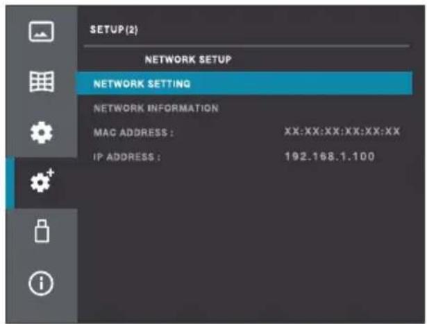
- Input the projector's IP address as displayed on the network settings screen into the web browser's URL field as shown below.
If the IP address displayed on the screen is "192.168.1.100"
Enter "http://192.168.1.100/index.html" into the URL input field.
After a moment, the HTTP server screen will be displayed on the web browser.

- Click the [Login] button in the upper left of the screen.
The screen for setting the login password appears the first time you click the [Login] or after you have reset the factory defaults in the on-screen menu.
- Once the password has been set, the login password input screen will appear the next time you click the [Login] button.

- Input your desired login password and the same password again, then click the [OK].
The login password input screen is displayed.
- The password can be changed on the HTTP server screen under [General Setup].

- Input the password set in step 6, then click the [Login].
The HTTP server screen is displayed.
| Network Display System > System Status | |
| System Status General Setup Picture Setup Image Setup Network Setup Logo | Model Name XP-P701U |
| Versions | |
| Firmware Version | |
| LAN Status | |
| IP Address 192.168.1.100 | |
| Subnet Mask 255.255.255.0 | |
| Default Gateway 192.168.1.1 | |
| Wire MAC Address | |
The settings on the HTTP server screen are as follows:
| System Status Model | Name Displays the device model name. | ||
| Versions This displays the projector's firmware version. | |||
| LAN Status This displays the LAN connection status. | |||
| General Setup Change | Password for Webpage | The login password can be changed here. | |
| Projector Name Enter the device name when controlling it over the network. | |||
| Power & Input This turns the power on and off and switches the signal. | |||
| Picture Setup Brightness | This adjusts the brightness of the projected image. | ||
| Contrast This adjusts the contrast of the projected image. | |||
| Sharpness This adjusts the sharpness of the projected image. | |||
| Color Temperature (Red/Green/Blue) | This adjusts the color temperature of the projected image. | ||
| Image Setup Aspect | This switches the projected image's aspect ratio. | ||
| Freeze This switches screen freeze on and off. | |||
| V Keystone | This corrects for vertical keystone distortion. | ||
| H Keystone | This corrects for horizontal keystone distortion. | ||
| Corner correction | TopLeft_x | This corrects for distortion in the upper left corner. | |
| TopLeft_y | |||
| TopRight_x | This corrects for distortion in the upper right corner. | ||
| TopRight_y | |||
| BottomLeft_x | This corrects for distortion in the lower left corner. | ||
| BottomLeft_y | |||
| BottomRight_x | This corrects for distortion in the lower right corner. | ||
| BottomRight_y | |||
| Network Setup | LAN Setup Obtain an IP address automatically Use the following IP address. | This select whether to enable or disable DHCP. When DHCP is disabled, set the IP address, subnet mask, gateway, and DNS below. | |
| Network Setup Crestron control IP Address Sets the options for Crestron control. | |||
| PJLink Setup Password Enable Select on or off for password setting. | |||
| Confirm Password Re-enter the PJLink password to confirm. | |||
| Network Service AMX Beacon Select whether or not to send an AMX beacon.- Default: Off (not sent) | |||
| Logo | Choose File | Select the image to be used as the logo. | |
| Update | Sends the selected logo image to the projector. | ||
NOTE:
• Always click [APPLY] after making a change to any General Setup or Network Setup setting.
- Any changes to the Network Service settings will be reflected the next time the projector is turned on.
- When you enter the password pay enough attention to people around for the password abuse prevention. If you have anxiety the password is cheated, change the password immediately.
- When using the projector in a network environment, always follow the network administrator's instructions to configure the settings.
- Depending on your network environment, the display speed or button response may be slow, or operations may not be accepted. In such cases, consult your network administrator.
Also, if you continue to operate the buttons, the projector may stop responding. In such cases, wait a while and then perform the operation again. If the projector still does not respond after waiting a while, turn the power off then back on.
- If the network settings screen does not appear in your web browser, press the Ctrl + F5 keys to refresh the web browser's display.
- The projector uses JavaScript and cookies, so configure your browser to enable these functions. The setting method varies depending on the firmware version. Refer to the help file or other explanations for the software.
- About Proxy Servers
Depending on the type and setting method of the proxy server, operation of the web browser via the proxy server may not be possible. Depending on the type of proxy server, phenomena such as what was actually set not being displayed due to the effect of caching, or settings made from the web browser not being reflected, may occur. We recommend you avoid using a proxy server if possible.
TIP:
- If you forget your password, go to [SETUP(2)] → [RESTORE FACTORY SETTINGS] in the unit's on-screen menu to reset the password. Using [RESTORE FACTORY SETTINGS] will return all settings to the factory default.
• What is PJLink?
PJLink is a standardization of protocol used for controlling projectors of different manufacturers. This standard protocol is established by Japan Business Machine and Information System Industries Association (JBMIA) in 2005.
- The CRESTRON settings are required only for use with CRESTRON ROOMVIEW.
For more information, visit https://www.crestron.com
7-4. Registering the Background Logo
An image can be sent from a computer to the projector and registered as the background logo. On the projector's HTTP server screen, display the [Logo] tab, then click [Choose File]. Next, select the image file you want to display on the logo screen, then update the background logo.

Conditions for logo images
* File size: Within 500 KB
* Image size: Within the projector's resolution (1920 × 1200 dots)
* File format: JPEG (full color)
Once registered, if [BACKGROUND] in the on-screen menu's [IMAGE OPTIONS] is set to [LOGO], the logo image will be displayed in the background when there is no signal.
If the logo image is smaller than the projector's resolution, the logo image is displayed in the center and the surrounding area is black.
NOTE:
- Make sure the projector is powered on before clicking "Update". The logo image cannot be transmitted if the projector is in Sleep or Standby mode.
8. Maintenance
8-1. Cleaning the Lens

WARNING
- Turn off the power, unplug the power plug from the socket and remove the lens for cleaning. If the unit turns on while cleaning the lens, the strong light from the lens could damage your eyes. It could also burn your fingers.
- Do not use a spray containing flammable gas to remove dust attached to the lens, etc. Doing so may result in fire.
- The projector has a plastic lens. Use a commercially available plastic lens cleaner.
- Do not scratch or mar the lens surface as a plastic lens is easily scratched.
- Never use alcohol or glass lens cleaner as doing so will cause damage to the plastic lens surface.
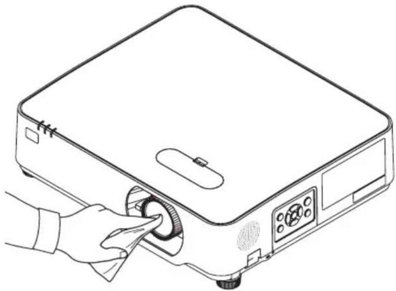
8-2. Cleaning the Cabinet

WARNING
- Turn off the projector, and unplug the projector before cleaning.
- Please do not use a spray containing flammable gas to remove dust attached to the cabinet. Doing so may result in fires.
Turn off the projector, and unplug the projector before cleaning.
- Use a dry soft cloth to wipe dust off the cabinet.
If heavily soiled, use a mild detergent.
- Never use strong detergents or solvents such as alcohol or thinner.
- When cleaning the ventilation slits or the speaker using a vacuum cleaner, do not force the brush of the vacuum cleaner into the slits of the cabinet.
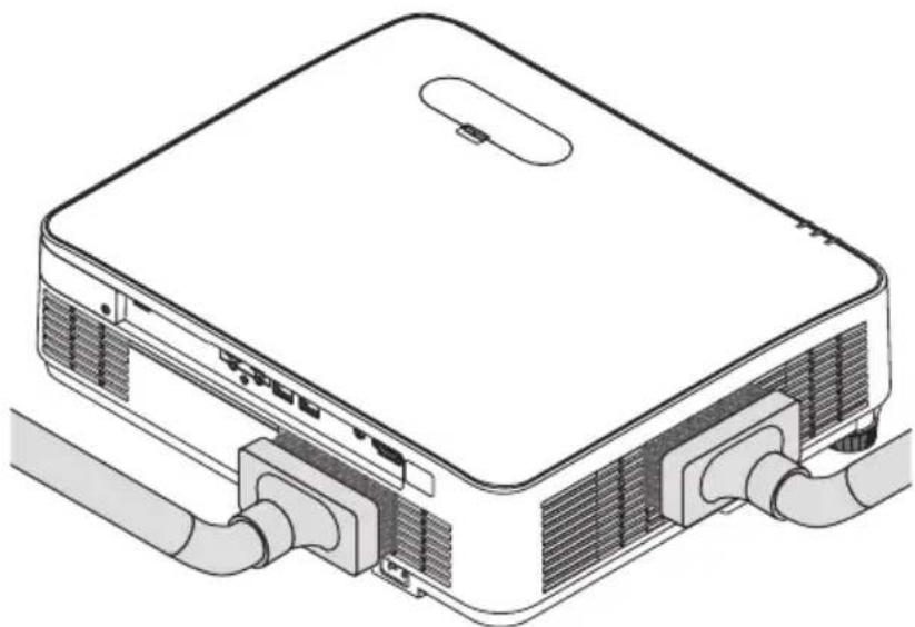
Vacuum the dust off the ventilation slits or the speaker.
- Poor ventilation caused by dust accumulation in ventilation openings can result in overheating and malfunction. These areas should be cleaned regularly.
- Do not scratch or hit the cabinet with your fingers or any hard objects
- Contact your dealer for cleaning the inside of the projector.
NOTE:
- Do not apply volatile agent such as insecticide on the cabinet, the lens, or the screen. Do not leave a rubber or vinyl product in prolonged contact with it. Otherwise the surface finish will be deteriorated or the coating may be stripped off.
9. Appendix
9-1. Setting Up the Screen and the Projector
Use this to get a general idea of what the screen size will be when set in a certain position, what size screen you will need, and what distance you will need to project images of the desired size.
The projection distance range at which focusing is possible is 0.68 m to 11.47 m. Install within this range.

* The figures indicated for "height of screen from projector lens center" on the projection distance table are for a lens shift of 44% V.
Reading the Table
From the upper table on this page, to project wide images on a 150 screen, install at about 3.5 m from the front.
Also, from the lower table we can see that about 1.9 m are required from the projector's lens center to the upper edge of the screen. Use this to see whether or not enough height can be provided from the projector to the ceiling and for installing the screen. The diagram shows the projection distance when the projector is installed horizontally. The projected image can be moved up and down, left and right using the lens shift function. (→ page 24)
Tables of screen sizes and dimensions

Screen width
| Size (inches) | Screen width Screen height | |||
| (cm) (inches) | (cm) (inches) | |||
| 30 64.6 25.4 | 40.4 15.9 | |||
| 40 86.2 33.9 | 53.8 21.2 | |||
| 60 129.2 50.9 | 80.8 31.8 | |||
| 80 172.3 67.8 | 107.7 42.4 | |||
| 90 193.9 76.3 | 121.2 47.7 | |||
| 100 215.4 84.8 | 134.6 53.0 | |||
| 120 258.5 101 | 18 161.5 63.6 | |||
| 150 323.1 127 | 2 201.9 79.5 | |||
| 180 387.7 152 | 6 242.3 95.4 | |||
| 200 430.8 169 | 6 269.2 106.0 | |||
| 240 516.9 203 | 5 323.1 127.2 | |||
| 250 538.5 212 | 0 336.5 132.5 | |||
| 270 581.6 229 | 0 363.5 143.1 | |||
| 300 646.2 254 | 4 403.9 159.0 | |||
Example of installation on a desktop
The diagram below shows an example of when the projector is used on a desktop.
Horizontal projection position: Equal distance to the left and right from the center of the lens Vertical projection position: (see table below)

(NOTE) Height from lens center to lower edge of screen (with tilt feet screwed in)
| Screen size (inches) | Throw distance L Height H | ||||||
| (m) (inches) (cm) (inches) | |||||||
| Wide Tele Wide Tele 0%V - 44%V 0%V - 44%V | |||||||
| 30 0.68 1 | 12 26.8 44.1 | -20.2 - -2.4 | -7.9 - -1.0 | ||||
| 40 0.92 1 | 50 36.1 59.2 | -26.9 - -3.2 | -10.6 - -1.3 | ||||
| 60 1.39 2 | 27 54.7 89.4 | -40.4 - -4.8 | -15.9 - -1.9 | ||||
| 80 1.86 3 | 04 73.3 119.5 | -53.8 - -6.5 | -21.2 - -2.5 | ||||
| 90 2.10 3 | 42 82.6 134.6 | -60.6 - -7.3 | -23.8 - -2.9 | ||||
| 100 | 2.34 3.80 | 91.9 149.7 | -67.3 - -8.1 | -26.5 - -3.2 | |||
| 120 | 2.81 | 4.57 | 110.5 | 179.9 | -80.8 - -9.7 | -31.8 - -3.8 | |
| 150 | 3.52 | 5.72 | 138.5 | 225.1 | -101.0 - -12.1 | -39.7 - -4.8 | |
| 180 | 4.23 | 6.87 | 166.4 | 270.4 | -121.2 - -14.5 | -47.7 - -5.7 | |
| 200 | 4.70 | 7.63 | 185.0 | 300.5 | -134.6 - -16.2 | -53.0 - -6.4 | |
| 240 | 5.65 | 9.17 | 222.2 | 360.9 | -161.5 - -19.4 | -63.6 - -7.6 | |
| 270 | 6.35 | 10.32 | 250.1 | 406.1 | -181.7 - -21.8 | -71.5 - -8.6 | |
| 300 | 7.06 | 11.47 | 278.1 | 451.4 | -201.9 - -24.2 | -79.5 - -9.5 | |
Lens shifting range
This projector is equipped with a lens shift function ( → page 24) for adjusting the image position using dials. Lens shifting is possible within the range shown below.
NOTE:
• In case lens shifted volume exceeds the below illustrated range, blur and shade may appear around ends of projected image.
Legend: V "Vertical" refers to the screen height and H "Horizontal" refers to the screen width. The lens shift range is expressed as a ratio of height and width, respectively.
Lens shifting range:
Vertical direction: +44%, -0%
Horizontal direction: ±20%
DESKTOP FRONT, DESKTOP REAR

CEILING FRONT, CEILING REAR

(Example) When using to project on a 150" screen
According to the "Table of screen sizes and dimensions" (→ page 88), H = 127.2"/323.1 cm, V = 79.5"/201.9 cm.
Adjustment range in the vertical direction: the projected image can be moved upwards 0.44 × 79.5''/201.9 cm ≈ 35.0''/89 cm (when the lens is at the center position).
Adjustment range in the horizontal direction: the projected image can be moved to the left 0.20 × 127.2''/323.1 cm ≈ 25.4''/65 cm, to the right approximately 25.4''/65 cm.
* Figures differ by several % because the calculation is approximate.
9-2. Compatible Input Signal List
| Signal name Resolution ( dots ) Aspect ratio | Refresh Rate ( Hz ) | ||
| VGA 640 | × 480 4 : 3 60 | ||
| SVGA 800 | × 600 4 : 3 60 | ||
| XGA 1024 | × 768 4 : 3 60 | ||
| HD 1280 | × 720 16 : 9 60 | ||
| WXGA | 1280 × 768 15 : 9 60 | ||
| 1280 × 800 16 : 10 60 | |||
| 1366 × 768 16 : 9 60 | |||
| Quad-VGA 1280 | × 960 4 : 3 60 | ||
| SXGA 1280 | × 1024 5 : 4 60 | ||
| SXGA+ 1400 | × 1050 4 : 3 60 | ||
| WXGA+ 1440 | × 900 16 : 10 60 | ||
| WXGA++ | 1600 × 900 16 : 9 60 | ||
| WSXGA+ | 1680 × 1050 | 16 : 10 60 | |
| Full HD | 1920 × 1080 | 16 : 9 60* | 1 |
| WUXGA | 1920 × 1200 | 16 : 10 60* | 1 |
| UWFHD | 2560 × 1080 | 21 : 9 60 | |
| 4K UHD | 3840 × 2160 | 16 : 9 30 | |
| HDTV(1080p) | 1920 × 1080 | 16 : 9 24/50/60 | |
| HDTV(1080i) | 1920 × 1080 | 16 : 9 50/60 | |
| HDTV (720p) | 1280 × 720 16 : 9 50/60 | ||
| SDTV (480p) | 720 × 480 4:3 / 16:9 60 | ||
| SDTV (576p) | 720 × 576 4:3 / 16:9 50 | ||
| SDTV (480i) | 720 × 480 4:3 / 16:9 60 | ||
| SDTV (576i) | 720 × 576 4:3 / 16:9 50 | ||
*1 Native resolution
If a signal except "Native Resolution" is input, the scaling may cause uneven thickness of characters and ruled lines, and blurred colors.
9-3. Specifications
This section provides technical information about projector's performance.
| Model name P701U-W P621U-W | ||||
| Method Three primary color liquid crystal | shutter projection method | |||
| Specifications of main parts | ||||
| Liquid crystal panel | ||||
| Projection lens F = 1.58 - 2.02, f = 1 | 5.3 - 24.6 mm, Zoom Ratio = 1.6 | |||
| Light source Laser diode with Phosphor | ||||
| Optical device Optical isolation by dichroic mirror, combining by dichroic prism | ||||
| Light output (*2) | 7000 lm (*3)7400 lm (Center) | 6200 lm (*3)6500 lm (Center) | ||
| Screen size (throw distance) 30 to 300 inches (0.7-11.5 m) | ||||
| Color reproducibility 10-bit color processing (approx. 1.07 billion colors) | ||||
| Scanning frequency | ||||
| Input/output terminals | ||||
| HDMI | Video input | Type A × 2Deep Color, LipSync, HDCP (*4) | ||
| Audio input | Sampling frequency: 32/44.1/48 kHzSampling bit: 16/20/24 bit | |||
| HDBaseT | Video input | RJ-45 × 1, Deep Color, LipSync, HDCP (*4) | ||
| Audio input | Sampling frequency: 32/44.1/48 kHzSampling bit: 16/20/24 bit | |||
| Audio output | Stereo mini jack × 1(Common to all signals) | |||
| USB | USB type A × 1, 5.0 V/2.0 A power supply | |||
| LAN | RJ-45 × 1, 10BASE-T/100BASE-TX | |||
| Control Terminals | ||||
| RS-232C | D-Sub 9-pin × 1 | |||
| Built-in Speaker | 16 W (monaural) | |||
| Usage environment (*5) | Operating temperature: 0 to 45°C / 32 to 113°FOperating humidity: 20 to 80% (with no condensation) | |||
| Storage temperature: -10 to 50°C / 14 to 122°FStorage humidity: 20 to 80% (with no condensation) | ||||
| Operating altitude: 0 to 2600 m/8500 feet(1600 to 2600 m/5500 to 8500 feet: Set [FAN MODE] to [HIGH ALTITUDE]) | ||||
| Power supply | 100-240 VAC, 50/60 Hz | |||
| Power consumption | 375 W (100–130 VAC)365 W (200–240 VAC) | 315 W (100–130 VAC)310 W (200–240 VAC) | ||
| Power consumption (Standby state) | ||||
| STANDBY MODE | NORMAL 0.31 W | (100–130 VAC) / 0.38 W (200–240 VAC) | ||
| NETWORK STANDBY | 0.8 W (100–130 VAC) / 1.0 W (200–240 VAC) | |||
| Rated input current | 5.0 A (100 -130 VAC) -2.0 A (200 -240 VAC) | 3.8 A (100 -130 VAC) -1.6 A (200 -240 VAC) | ||
| Power cord specification 10 A or higher | ||||
| External dimensions | 18.9" (width) × 4.8" (height) × 16" (depth)/480 (width) × 122 (height) × 407 (depth) mm(not including protrusions) | |||
| 18.9" (width) × 5.6" (height) × 16" (depth)/480 (width) × 142.5 (height) × 407 (depth) mm(including protrusions) | ||||
| Weight 21.2 lbs / 9.6 kg 20.7 lbs / 9.4 kg | ||||
*1 Effective pixels are more than 99.99%.
*2 Brightness when PICTURE MANAGEMENT is set to [HIGH-BRIGHT] and LIGHT MODE is set to [NORMAL: 100%].
The brightness will decrease slightly if any other mode is selected.
*3 Compliance with ISO 21118-2020
*4 If you are unable to view material via the HDMI input, this does not necessarily mean the projector is not functioning properly. With the implementation of HDCP, there may be cases in which certain content is protected with HDCP and might not be displayed due to the decision/intention of the HDCP community (Digital Content Protection, LLC).
Video: Deep Color, 8/10/12-bit, Lip Sync.
Audio: LPCM; up to 2 ch, sample rate 32/44.1/48 KHz, sample bit; 16/20/24-bit
HDMI: Supports HDCP 1.4
HDBaseT: Supports HDCP 1.4
*5 If the ambient temperature is high, the light source luminance (brightness) may automatically decrease due to the projector's protection function.
(This is typically around 33° C, but this varies depending on the operating environment.)
- These specifications and the product's design are subject to change without notice.
For additional information visit:
US: https://business.sharpusa.com/
Europe: https://www.sharpnecdisplays.eu
Global: https://www.sharp-nec-displays.com/global/
For information on our optional accessories, visit our website or see our brochure.
9-4. Cabinet Dimensions
Unit: mm (inch)

9-5. Pin assignments and signal names of main terminals
HDMI 1/HDMI 2 Terminal (Type A)

| Pin No. Signal | |
| 1 TMDS | Data 2+ |
| 2 TMDS | Data 2 Shield |
| 3 TMDS | Data 2- |
| 4 TMDS | Data 1+ |
| 5 TMDS | Data 1 Shield |
| 6 TMDS | Data 1- |
| 7 TMDS | Data 0+ |
| 8 TMDS | Data 0 Shield |
| 9 TMDS | Data 0- |
| 10 TMDS | Clock + |
| 11 TMDS | Clock Shield |
| 12 TMDS | Clock- |
| 13 CEC | |
| 14 Disconnection | |
| 15 SCL | |
| 16 SDA | |
| 17 DDC/CEC grounding | |
| 18 +5 V power supply | |
| 19 Hot plug detection | |
HDBaseT/LAN Port (RJ-45)

| Pin No. Signal |
| 1 TxD+/HDBT0+ |
| 2 TxD−/HDBT0− |
| 3 RxD+/HDBT1+ |
| 4 Disconnection/HDBT2+ |
| 5 Disconnection/HDBT2− |
| 6 RxD−/HDBT1− |
| 7 Disconnection/HDBT3+ |
| 8 Disconnection/HDBT3− |
USB Port (Type A)
![graph TD A["1"] --> B["2"] B --> C["3"] C --> D["4"]](/content/2026/08/1618187/images/16a4a25f4298ad99d5c01bc9b081352c7bcc074a27835f2e664cced477c09243.jpg)
| Pin No. Signal | |
| 1 | VBUS |
| 2 | D- |
| 3 | D+ |
| 4 Grounding | |
RS-232C Port (D-Sub 9 Pin)

| Pin No. Signal |
| 1 Unused |
| 2 RxD reception data |
| 3 TxD transmission data |
| 4 Unused |
| 5 Grounding |
| 6 Unused |
| 7 RTS transmission request |
| 8 CTS transmission allowed |
| 9 Unused |
9-6. PC Control Codes and Cable Connection
PC Control Codes
Command Format - A
| Function Code Data | |||||||
| POWER ON 02H 00H 00H 00H 00H 02H | |||||||
| POWER OFF 02H 01H 00H 00H 00H 03H | |||||||
| INPUT SELECT HDMI1 02H 03H 00H 00H 02H 01H A1H A9H | |||||||
| INPUT SELECT HDMI2 02H 03H 00H 00H 02H 01H A2H AAH | |||||||
| INPUT SELECT HDBaseT 02H 03H 00H 00H 02H 01H BFH C7H | |||||||
| INPUT SELECT USB-A 02H 03H 00H 00H 02H 01H 1FH 27H | |||||||
| PICTURE MUTE ON 02H 10H 00H 00H 00H 12H | |||||||
| PICTURE MUTE OFF 02H 11H 00H 00H 00H 13H | |||||||
| SOUND MUTE ON 02H 12H 00H 00H 00H 14H | |||||||
| SOUND MUTE OFF 02H 13H 00H 00H 00H 15H | |||||||
Command Format - B
| Function Code Data | |||||||||
| POWER ON | P | O | W | R | 1 | ||||
| POWER OFF | P | O | W | R | 0 | ||||
| INPUT SELECT HDMI1 | I | R | G | B | 3 | 1 | |||
| INPUT SELECT HDMI2 | I | R | G | B | 3 | 2 | |||
| INPUT SELECT HDBaseT | I | N | E | T | 5 | 1 | |||
| INPUT SELECT USB-A | I | U | S | B | 4 | 1 | |||
| AV MUTE OFF | I | M | B | K | 0 | ||||
| AV MUTE ON | I | M | B | K | 1 | ||||
| SOUND MUTE OFF | M | U | T | E | 0 | ||||
| SOUND MUTE ON | M | U | T | E | 1 | ||||
NOTE:
• Command formats A and B are identified automatically.
-
- Contact your local dealer for a full list of the PC Control Codes if needed.
Cable Connection
Communication Protocol
| Baud rate 38400 bps | |
| Data length 8 bits | |
| Parity No parity | |
| Stop bit One bit | |
| X on/off None | |
| Communications procedure Full duplex |
NOTE:
- Depending on the equipment, a lower baud rate may be recommended for long cable runs.
RS232C Terminal (D-Sub 9P)

NOTE:
- Pins 1, 4, 6 and 9 are no used.
- Jumper "Request to Send" and "Clear to Send" together on both ends of the cable to simplify cable connection.
- For long cable runs it is recommended to set communication speed within projector menus to 9600 bps.
9-7. About the ASCII Control Command
This device supports the common ASCII Control Command for controlling our projector and monitor.
Please visit our web site for detailed information about the command.
https://www.sharp-nec-displays.com/dl/en/pj_manual/lineup.html
How to connect with an external device
There are two methods to connect the projector with an external device such as a computer.
- Connection thru the serial port.
Connects the projector to a computer by a serial cable (a cross cable).
- Connection via network (LAN)
Connects the projector to a computer by a LAN cable.
Concerning to the type of LAN cable, please ask to your network administrator.
Connection interface
- Connection thru the serial port.
Communication Protocol
| Item Information | |
| Baud rate 38400/19200/9600/4800 bps | |
| Data length 8 bits | |
| Parity bit No parity | |
| Stop bit 1 bit | |
| Flow control None | |
| Communications procedure Full duplex | |
- Connection via network
Communication Protocol (Connection via LAN)
| Item Information | |
| Communication speed Set automatically | (10/100 Mbps) |
| Supported standard IEEE802.3 (10BASE-T) | |
Use the TCP port number 7142 for transmitting and receiving command.
Parameters for this device
Input command
| Input terminal Response Parameter | ||
| HDMI1 | hdmi1 | hdmi1 or hdmi |
| HDMI2 | hdmi2 | hdmi2 |
| HDBaseT | hdbaset | hdbaset |
| USB-A | usb-a | usb-a |
Status command
| Response Error Status | |
| error:temp Temperature error | |
| error:fan Fan trouble | |
| error:light Light source trouble | |
| error:system System trouble |
9-8. Troubleshooting
This section helps you resolve problems you may encounter while setting up or using the projector.
Common Problems & Solutions
| Problem Check These Items | |
| Does not turn on or shut down | Check that the power cord is plugged in and that the power button on the projector cabinet or the remote control is on. (→ pages 18, 20)Check to see if the projector has overheated. If there is insufficient ventilation around the projector or if the room where you are presenting is particularly warm, move the projector to a cooler location.The light module may fail to light. Wait a full minute and then turn on the power again.Set [FAN MODE] to [HIGH ALTITUDE] when using the projector at altitudes approximately 5500 feet/1600 meters or higher. Using the projector at altitudes approximately 5500 feet/1600 meters or higher without setting to [HIGH ALTITUDE] can cause the projector to overheat and the projector could shut down. If this happens, wait a couple minutes and turn on the projector. (→ page 54)If you turn on the projector immediately after the light module is turned off, the fans run without displaying an image for some time and then the projector will display the image. Wait for a moment.In case it's hard to think the trouble is not caused on the above mentioned conditions, unplug the power cord from the outlet. Then wait 5 minutes before plugging it in again. (→ page 33) |
| Will turn off | Have you set the time in [POWER MANAGEMENT] on the on-screen menu? (→ page 64) |
| No picture | Check if the appropriate input is selected. (→ page 22) If there is still no picture, press the SOURCE button or one of the source buttons again.Ensure your cables are connected properly.Use menus to adjust the brightness and contrast. (→ page 48)Check that the AV-MUTE (image off) buttons are not pressed.Reset the settings or adjustments to factory preset levels using the [RESTORE FACTORY SETTINGS] in the Menu. (→ page 68)If the HDMI 1 IN or the HDMI 2 IN signal cannot be displayed, try the following.- Reinstall your driver for the graphics card built in your computer, or use the updated driver.For reinstalling or updating your driver, refer to the user guide accompanied with your computer or graphics card, or contact the support center for your computer manufacturer.Install the updated driver or OS on your own responsibility.We are not liable for any trouble and failure caused by this installation.Signals may not be supported depending on the HDBaseT transmission device. RS-232C cannot be used in certain cases as well.Be sure to connect the projector and notebook PC while the projector is in standby mode and before turning on the power to the notebook PC.In most cases the output signal from the notebook PC is not turned on unless connected to the projector before being powered up.* If the screen goes blank while using your remote control, it may be the result of the computer's screen-saver or power management software. |
| Picture suddenly becomes dark | A hot room may trigger the projector's protection functions, which can result in a temporary reduction in luminance (brightness). Reduce the temperature in the room.When the DYNAMIC CONTRAST function is enabled, the brightness may decrease depending on the image being displayed. (→ page 48) |
| Image isn't square to the screen | Reposition the projector to improve its angle to the screen. (→ page 23)Use the Keystone correction function to correct the trapezoid distortion. (→ page 29) |
| Picture is blurred • Adjust the focus. (→ page 26)• Reposition the projector to improve its angle to the screen. (→ page 23)• Ensure that the distance between the projector and screen is within the adjustment range of the lens. (→ page 87)• Has the lens been shifted by an amount exceeding the guaranteed range? (→ page 25)• Condensation may form on the lens if the projector is cold, brought into a warm place and is then turned on. Should this happen, let the projector stand until there is no condensation on the lens. | |
| The HDMI input signal is not projected correctly | • The HDMI signal level may not be detected correctly. Check the signal level of the device connected to either the HDMI 1 or HDMI 2 input terminal and try changing the setting in [HDMI SETTINGS] in the on-screen menu under [SETUP(1)]. (→ page 56) |
| No sound • Is the volume turned down? (→ page 32)Or, is the [MUTE] function in the on-screen menu set to [ON]? (→ page 56) | |
| Remote control does not work | • Aim the remote control's infrared transmitter towards the projector's remote control receiver. (→ page 16)• Install new batteries.(→ page 15)• Make sure there are no obstacles between you and the projector.• Stand within 23 feet (7 m) of the projector. (→ page 16)• If a [CONTROL ID] has been set, check whether the ID number for the remote control matches the ID number for the projector. (→ page 67) |
| Indicator is lit or blinking | • See the POWER/STATUS/LIGHT Indicator. (→ page 104) |
For more information contact your dealer.
9-9. Indicator Message
Feature of each indicator
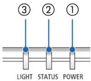
① POWER indicator
② STATUS indicator
③ LIGHT indicator
Normal indicator display
| POWER STATUS LIGHT Projector status | |||
| Off Off Off | Power is off | ||
 Orange(Slow flashing) Orange(Slow flashing) | Off Off | Standby ([NORMAL] standby mode) | |
| [TDSX]Orange(Lit) | Off Off | Standby ([NETWORK STANDBY] standby mode) | |
 Green(Lit) Green(Lit) | Off Off | Standby ([SLEEP] standby mode) | |
 Blue(Lit) Blue(Lit) | Off Green | (Lit) | Power is on ([NORMAL] light mode) |
 Blue(Lit) Blue(Lit) | Off Green | (Flashing) | Power is on ([SILENT] or [LONG LIFE] light mode) |
 Green(Quick flashing) Green(Quick flashing) | Off Off | Projector is cooling down | |
 Green(Slow flashing) Green(Slow flashing) | Off Off | Ready mode (→ page 64) | |
Indicator display when there is an abnormality
| POWER STATUS LIGHT Projector status | |||
 Blue(Lit) Blue(Lit) |  Orange(Lit) Orange(Lit) | Other statuses | When a button on the projector is pressed while the control panel keys are locked |
| When the ID numbers of the projector and remote control do not match | |||
 Red(Quick flashing) Red(Quick flashing) |  Off Off Off Off | A temperature error was detected. Check if the air intake and exhaust vents are blocked. | |
 Red(Lit) Red(Lit) | Other statuses Other statuses | Hardware error.Please contact your dealer. | |
 Red(Quick flashing) Red(Quick flashing) | Other statuses Other statuses | ||
When the thermal protector is activated:
When inside temperature of the projector becomes too high or low, the POWER indicator starts to red blink in a short cycle. After this happened, the thermal protector will activate and the projector may be turned off.
In this case, please take the below measures:
- Pull out the power plug from the wall inlet.
- Place the projector in cool place if it has been placed in high ambient temperature.
- Clean the exhaust vent if dust has accumulated on.
- Leave the projector for about one hour until inside temperature gets lower.
9-10. Troubleshooting Check List
Before contacting your dealer or service personnel, check the following list to be sure repairs are needed also by referring to the "Troubleshooting" section in your user's manual. This checklist below will help us solve your problem more efficiently.
* Print this page and the next page for your check.
Frequency of occurrence:
□ always □ sometimes (How often? ____) □ other (____)
Power

![Shut down during operation. Power cord's plug is fully inserted into the wall outlet. [POWER MANAGEMENT] is turned off (only models with the [POWER MANAGEMENT] function).](/content/2026/08/1618187/images/b9b00e37c6f2030ea8b506c139f99638bbcd7653c1b8c306f45a6b32198c47ff.jpg)
Video and Audio
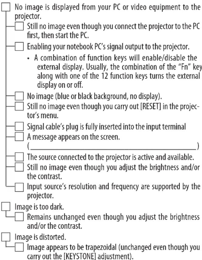
![Parts of the image are lost. Still unchanged even though you carry out [RESET] in the projector's menu. Image is shifted in the vertical or horizontal direction. Input source's resolution and frequency are supported by the projector. Some pixels are lost. Image is flickering. Still unchanged even th…](/content/2026/08/1618187/images/34bf3ee9f68c7d1ebe2bac55a8a39c5d2d4024154672642997491425a2fdfa6d.jpg)
Other

![Buttons on the projector cabinet do not work (only models with the [CONTROL PANEL LOCK] function) [CONTROL PANEL LOCK] is not turned on or is disabled in the menu.](/content/2026/08/1618187/images/0198be65ac6ff8c91b22bcaa2285417f5a12036236ec1e0d59a1d24cb546875a.jpg)
In the space below please describe your problem in detail.
Information on application and environment where your projector is used
Projector
Model number:
Serial No.:
Date of purchase:
Light module operating time (hours):
LIGHT MODE: □ NORMAL □ SILENT
□ LONG LIFE
Information on input signal:
Horizontal synch frequency [ ] kHz
Vertical synch frequency [ ] Hz
Synch polarity H □ (+) □ (−)
V
Indicator:
Steady light [ ]
Flashing light [ ] cycles
Remote control model number:
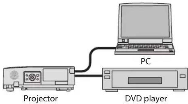
Signal cable
SHARP standard or other manufacturer's cable?
Model number: Length: inch/m
Distribution amplifier
Model number:
Switcher
Model number:
Adapter
Model number:
Installation environment
Screen size: inch
Screen type: □ White matte □ Beads □ Polarization
□ Wide angle □ High contrast
Throw distance: feet/inch/m
Orientation: □ Ceiling mount □ Desktop
Power outlet connection:
☐ Connected directly to wall outlet
☐ Connected to power cord extender or other (the number of connected equipment ____ )
☐ Connected to a power cord reel or other (the number of connected equipment ____ )

Computer
Manufacturer:
Model number:
Notebook PC □ / Desktop □
Native resolution:
Refresh rate:
Video adapter:
Other:
Video equipment
VCR, DVD player, Video camera, Video game or other
Manufacturer:
Model number:
SHARP
SHARP CORPORATION
- CHECK THE PRODUCT OVERVIEW, SUPPLIED ITEMS AND PART NAMES
- PROJECTING AN IMAGE (BASIC OPERATION)
- CONVENIENT FEATURES
- USING THE VIEWER (USB-A)
- USING ON-SCREEN MENU
- MAKING CONNECTIONS
- CONNECTING TO A NETWORK
- MAINTENANCE
- APPENDIX
- INTRODUCTION
- NOTES
- FCC INFORMATION (FOR USA ONLY)
- SUPPLIER'S DECLARATION OF CONFORMITY
- WARNING
- NOTE
- CABLE INFORMATION
- NOTICE CONCERNING ELECTROMAGNETIC INTERFERENCE (EMI) (FOR OTHER REGIONS)
- (FOR CUSTOMERS IN U.K.)
- IMPORTANT
- INFORMATION ON THE DISPOSAL OF THIS EQUIPMENT AND ITS BATTERIES
- (FOR GERMANY ONLY)
- MACHINE NOISE INFORMATION REGULATION - 3. GPSGV
- INFORMATION OF THE AUDIO OUT MINI JACK
- LASER SAFETY CAUTION
- FOR USA
- LIGHT MODULE
- RISK GROUPS
- ABOUT THE SYMBOLS
- EXAMPLES OF SYMBOLS
- SAFETY CAUTIONS
- PROJECTED LIGHT
- PROHIBITED
- PROJECTED LIGHT AND THE PICTOGRAM/LABEL INDICATED ON THE CABINET
- LABEL
- NOTES ON INSTALLATION AND MAINTENANCE
- PRECAUTIONS WHEN INSTALLING ON THE CEILING (TO THE DEALER AND THE INSTALLER)
- SECURING PERSONAL INFORMATION
- CAUTIONS FOR ENSURING THE PROJECTOR'S PERFORMANCE
- CLEARANCE FOR INSTALLING THE PROJECTOR
- ABOUT COPYRIGHT OF ORIGINAL PROJECTED PICTURES
- POWER MANAGEMENT FUNCTION
- STANDBY MODE (FACTORY PRESET: NORMAL)
- POWER MANAGEMENT (FACTORY PRESET: READY)
- REGISTER YOUR PROJECTOR! (FOR RESIDENTS IN THE UNITED STATES AND MEXICO)
- REGISTRATION INFORMATION AND SOFTWARE LICENSE
- INTRODUCTION TO THE PROJECTOR
- GENERAL
- LIGHT SOURCE · BRIGHTNESS
- INSTALLATION
- ° INSTALLATION AND PORTRAIT PROJECTION
- LENS SHIFT MECHANISM FOR ADJUSTING THE POSITION OF THE PROJECTED IMAGE EASILY
- VIDEOS
- HDMI INPUTS, HDBASET, AND OTHER INPUT TERMINALS
- [VIEWER] FUNCTION TO PROJECT STILL IMAGES SAVED IN A USB MEMORY
- NETWORK
- COMPATIBLE WITH WIRED LAN
- CRESTRON ROOMVIEW COMPATIBILITY
- CONVENIENT SOFTWARE APPLICATIONS
- ENERGY-SAVING
- WHAT'S IN THE BOX
- PART NAMES OF THE PROJECTOR
- FRONT
- LENS SHIFT COVER
- ZOOM LEVER
- LENS
- FOCUS RING
- LENS CAP
- INDICATORS
- REMOTE CONTROL SIGNAL SENSORS
- SPEAKER (MONAURAL)
- MAIN UNIT CONTROL PANEL
- SECURITY SLOT (K)
- SECURITY CHAIN OPENING
- TILT FEET
- MOUNTING THE LENS CAP STRAP
- REAR
- CONNECTION TERMINALS
- AC INPUT
- AIR INTAKE VENT
- REMOTE CONTROL SIGNAL SENSOR
- EXHAUST VENT
- CONTROLS/INDICATORS
- (POWER) BUTTON
- POWER INDICATOR
- STATUS INDICATOR
- LIGHT INDICATOR
- INPUT BUTTON
- MENU BUTTON
- EXIT BUTTON
- ▼▲◀▶ BUTTONS
- ENTER BUTTON
- (VOLUME -) BUTTON
- (VOLUME +) BUTTON
- (KEYSTONE CORRECTION) BUTTON
- TERMINAL PANEL FEATURES
- HDMI 1 TERMINAL (TYPE A)
- HDMI 2 TERMINAL (TYPE A)
- AUDIO OUT MINI JACK (STEREO MINI)
- HDBASET PORT (RJ-45)
- LAN PORT (RJ-45)
- USB PORT (TYPE A)
- RS-232C PORT (D-SUB 9 PIN)
- PART NAMES OF THE REMOTE CONTROL
- INFRARED TRANSMITTER
- POWER ON ( | ) BUTTON
- POWER STANDBY ( ⏻ ) BUTTON
- SOURCE BUTTON
- HDMI1 BUTTON
- HDMI2 BUTTON
- HDBASET BUTTON
- DISPLAYPORT BUTTON
- COMPUTER BUTTON
- AUTO ADJ. BUTTON
- VIDEO BUTTON
- USB-A BUTTON
- USB-B BUTTON
- APPS BUTTON
- PIP BUTTON
- NUMERIC KEYPAD BUTTON/CLEAR BUTTON
- ID SET BUTTON
- FREEZE BUTTON
- AV-MUTE BUTTON
- D-ZOOM (+)(−) BUTTON
- PAGE ▽/△ BUTTONS
- MOUSE L-CLICK BUTTON
- MOUSE R-CLICK BUTTON
- LIGHT BUTTON
- KEYSTONE BUTTON
- PICTURE BUTTON
- VOL. (+)(−) BUTTON
- ASPECT BUTTON
- FOCUS/ZOOM BUTTON
- INFO. BUTTON
- BATTERY INSTALLATION
- REMOTE CONTROL PRECAUTIONS
- OPERATING RANGE FOR WIRELESS REMOTE CONTROL
- FLOW OF PROJECTING AN IMAGE
- STEP
- CONNECTING YOUR COMPUTER/CONNECTING THE POWER CORD
- CONNECT YOUR COMPUTER TO THE PROJECTOR
- CONNECT THE SUPPLIED POWER CORD TO THE PROJECTOR
- CAUTION
- TURNING ON THE PROJECTOR
- REMOVE THE LENS CAP
- PRESS THE (POWER) BUTTON ON THE PROJECTOR CABINET OR THE POWER ON BUTTON ON THE REMOTE CONTROL
- TO SELECT A MENU LANGUAGE, FOLLOW THESE STEPS
- PRESS THE MENU BUTTON ON THE REMOTE CONTROL OR THE MAIN UNIT'S CONTROL PANEL
- USE THE ▲/▼ BUTTONS TO MOVE THE CURSOR TO THE [SETUP(2)] ICON, THEN PRESS THE ENTER BUTTON OR THE ▶ BUTTON
- CHECK THAT THE CURSOR IS SET TO [LANGUAGE], THEN PRESS THE ENTER BUTTON OR THE ▶ BUTTON
- USE THE ▲ OR ▼ BUTTON TO SELECT ONE OF THE 25 LANGUAGES FROM THE MENU
- PRESS THE ENTER BUTTON TO EXECUTE THE SELECTION
- SELECTING A SOURCE
- SELECTING BY PRESSING THE INPUT SELECTOR BUTTON
- TURN ON THE POWER OF THE COMPUTER OR DVD PLAYER CONNECTED TO THE PROJECTOR
- PRESS THE INPUT (INPUT SELECTOR) BUTTON
- USE THE ▲/▼ BUTTONS TO MOVE THE CURSOR TO THE TERMINAL WHOSE PICTURE YOU WANT TO PROJECT, THEN PRESS THE ENTER BUTTON
- SELECTING BY PRESSING THE HDMI1 OR HDMI2 BUTTON ON THE REMOTE CONTROL
- PRESS THE HDMI1 OR HDMI2 BUTTON ON THE REMOTE CONTROL
- ADJUSTING THE PICTURE SIZE AND POSITION
- ADJUSTING THE VERTICAL POSITION OF A PROJECTED IMAGE (LENS SHIFT)
- OPEN THE LENS SHIFT COVER
- TURN THE LENS SHIFT DIALS CLOCKWISE OR COUNTERCLOCKWISE
- CLOSE THE LENS SHIFT COVER
- TIP
- FOCUS
- ZOOM
- ADJUSTING THE TILT (TILT FOOT)
- TURN THE LEFT AND RIGHT TILT FEET TO ADJUST
- ADJUSTING FOR TRAPEZOIDAL DISTORTION (KEYSTONE CORRECTION)
- ABOUT THE TYPES OF GEOMETRIC CORRECTION FUNCTIONS ON THIS PROJECTOR
- PERFORMING HORIZONTAL/VERTICAL KEYSTONE CORRECTION
- PRESS THE ▼ (BUTTON ON THE MAIN UNIT'S CONTROL PANEL
- USE THE ▲/▼ BUTTONS TO MOVE THE CURSOR TO [H/V KEYSTONE], THEN PRESS THE ENTER BUTTON
- WHILE THE [H/V KEYSTONE] SCREEN IS DISPLAYED, USE THE ◀/▶ BUTTONS TO ADJUST THE LEFT/RIGHT TILT OF THE PROJECTED IMAGE
- H/V KEYSTONE
- WHILE THE [H/V KEYSTONE] SCREEN IS DISPLAYED, USE THE ▲/▼ BUTTONS TO ADJUST THE TRAPEZOIDAL DISTORTION IN THE VERTICAL DIRECTION
- REPEAT STEPS 3 AND 4 TO ADJUST THE TRAPEZOIDAL DISTORTION OF THE PROJECTED IMAGE
- ADJUSTING THE UNIT'S VOLUME
- ADJUSTING WITH THE OPERATION BUTTONS ON THE PROJECTOR
- WHEN THE ON-SCREEN MENU IS NOT DISPLAYED, PRESS THE ◀ (☐) / ▶ (☐) BUTTONS
- ADJUSTING USING THE REMOTE CONTROL
- PRESS THE REMOTE CONTROL'S VOL. +/- BUTTONS
- TURNING OFF THE PROJECTOR
- TO TURN OFF THE PROJECTOR
- WHEN MOVING THE PROJECTOR
- MUTING THE PICTURE AND SOUND (AV-MUTE)
- PRESS THE AV-MUTE BUTTON ON THE REMOTE CONTROL
- FREEZING A MOVIE (STILL IMAGE)
- PRESS THE FREEZE BUTTON ON THE REMOTE CONTROL
- ZOOMING PART OF THE PICTURE (PARTIAL ZOOM)
- PRESS THE D-ZOOM (+) BUTTON ON THE REMOTE CONTROL
- PRESS THE ▼▲◀▶ BUTTONS
- PRESS THE D-ZOOM (-) BUTTON
- ADJUSTING THE LUMINANCE (BRIGHTNESS) (LIGHT MODE)
- CHANGE [LIGHT MODE]
- PRESS THE MENU BUTTON
- USE THE ▲/▼ BUTTONS TO MOVE THE CURSOR TO THE [SETUP(1)] ICON, THEN PRESS THE ENTER BUTTON OR THE ▶ BUTTON
- PERFORM [LIGHT ADJUST]
- WHAT YOU CAN DO WITH THE VIEWER
- PROJECTING IMAGES STORED ON USB FLASH DRIVES (BASIC OPERATION)
- PRESS THE INPUT BUTTON
- USE THE ▼/▲ BUTTONS TO SELECT [USB-A], THEN PRESS THE ENTER BUTTON
- PRESS THE ENTER BUTTON ON THE VIEWER SCREEN
- BASIC OPERATIONS OF THE ON-SCREEN MENU
- STRUCTURE OF THE ON-SCREEN MENU SCREEN
- PREPARATION: TURN ON THE PROJECTOR'S AND PROJECT A PICTURE ONTO THE SCREEN
- PRESS THE ▼/▲ BUTTONS
- WITH THE CURSOR SET TO A MAIN MENU ICON, PRESS ▶ OR THE ENTER BUTTON
- USE THE ▼/▲ BUTTONS TO MOVE THE CURSOR TO THE DESIRED SUBMENU ITEM
- EXPLANATION OF A MENU SCREEN EXAMPLE
- CHANGING NUMBERS
- CONFIRMATION MESSAGE
- ON-SCREEN MENU LIST
- PICTURE
- PICTURE MANAGEMENT
- DYNAMIC CONTRAST
- CONTRAST
- BRIGHTNESS
- COLOR TEMPERATURE
- RED/GREEN/BLUE
- SHARPNESS
- IMAGE OPTIONS
- ASPECT RATIO
- ORIENTATION
- MENU POSITION
- BACKGROUND
- SETUP (1)
- DIRECT POWER ON
- AUTO POWER ON SELECT
- STANDBY MODE
- FAN MODE
- COOLING FAST
- CONTROL PANEL LOCK
- COMMUNICATION SPEED
- LIGHT MODE
- LIGHT ADJUST
- SOUND
- HDMI SETTINGS
- VIDEO LEVEL
- SETUP(2)
- LANGUAGE
- AUTO SETUP
- INPUT SEARCH
- AUTO KEYSTONE
- GEOMETRIC CORRECTION
- CORNERSTONE
- PINCUSHION
- PINCUSHION X/Y GAIN
- PINCUSHION X OFFSET
- PINCUSHION Y OFFSET
- GRID IMAGE TUNE
- RESET
- START-UP LOCK
- PIN CODE LOCK
- HOW TO INPUT THE PIN CODE
- PIN CODE CHANGE
- POWER MANAGEMENT
- TIMER
- READY COUNTDOWN
- TEST PATTERN
- NETWORK SETUP
- NETWORK SERVICE
- CONTROL ID
- HOW TO SET AND CHANGE IDS ON THE REMOTE CONTROL
- TURN ON THE PROJECTOR'S POWER
- PRESS THE ID SET BUTTON ON THE REMOTE CONTROL
- PRESS AND HOLD THE ID SET BUTTON ON THE REMOTE CONTROL, THEN PRESS A NUMBER BUTTON TO SET THE REMOTE CONTROL'S ID
- RELEASE THE ID SET BUTTON
- RESTORE FACTORY SETTINGS
- USB-A
- INFORMATION
- CONNECTING TO COMPUTERS AND VIDEO DEVICES
- CONNECTING TO A WIRED LAN
- EXAMPLE OF LAN CONNECTION
- CONNECTING TO A HDBASET TRANSMISSION DEVICE (SOLD COMMERCIALLY)
- CONNECTION EXAMPLE
- PORTRAIT PROJECTION (VERTICAL ORIENTATION)
- PRECAUTIONS DURING INSTALLATION
- DESIGN AND MANUFACTURING CONDITIONS FOR THE STAND
- REFERENCE DRAWINGS
- WHAT YOU CAN DO BY CONNECTING TO A NETWORK
- ENABLING THE PROJECTOR'S WIRED LAN FUNCTION
- PREPARATION
- CHECK THAT THE CURSOR IS SET TO [PROFILE], THEN PRESS THE ENTER BUTTON
- USE THE ▼/▲ BUTTONS TO SELECT [ENABLE], THEN PRESS THE ENTER BUTTON
- CHANGING THE IP ADDRESS
- USE THE ▼/▲ BUTTONS TO SELECT [DHCP], THEN PRESS THE ENTER BUTTON
- USE THE ▼/▲ BUTTONS TO SELECT [OFF], THEN PRESS THE ENTER BUTTON
- USE THE ▼/▲ BUTTONS TO SELECT [IP ADDRESS], THEN PRESS THE ENTER BUTTON
- USE THE ▼/▲ BUTTON TO CHANGE THE VALUE, THEN PRESS THE ENTER BUTTON
- REPEAT STEP 10 TO SET THE IP ADDRESS
- USE THIS SAME PROCEDURE TO SET [SUBNET MASK], [GATEWAY], [DNS], ETC
- USE THE ▼/▲ BUTTONS TO SET THE CURSOR TO [SET], THEN PRESS THE ENTER BUTTON
- CONNECTING TO THE PROJECTOR'S HTTP SERVER
- DISPLAY AND CONFIRM THE PROJECTOR'S IP ADDRESS
- USE THE NETWORK SETTINGS ON YOUR COMPUTER OR TABLET
- LAUNCH THE WEB BROWSER ON YOUR COMPUTER OR TABLET DEVICE
- REGISTERING THE BACKGROUND LOGO
- CONDITIONS FOR LOGO IMAGES
- CLEANING THE LENS
- CLEANING THE CABINET
- SETTING UP THE SCREEN AND THE PROJECTOR
- READING THE TABLE
- EXAMPLE OF INSTALLATION ON A DESKTOP
- LENS SHIFTING RANGE
- SPECIFICATIONS
- PIN ASSIGNMENTS AND SIGNAL NAMES OF MAIN TERMINALS
- HDMI 1/HDMI 2 TERMINAL (TYPE A)
- HDBASET/LAN PORT (RJ-45)
- PC CONTROL CODES AND CABLE CONNECTION
- PC CONTROL CODES
- CABLE CONNECTION
- ABOUT THE ASCII CONTROL COMMAND
- HOW TO CONNECT WITH AN EXTERNAL DEVICE
- CONNECTION INTERFACE
- PARAMETERS FOR THIS DEVICE
- INPUT COMMAND
- TROUBLESHOOTING
- INDICATOR MESSAGE
- FEATURE OF EACH INDICATOR
- WHEN THE THERMAL PROTECTOR IS ACTIVATED
- TROUBLESHOOTING CHECK LIST
- FREQUENCY OF OCCURRENCE
- POWER
- VIDEO AND AUDIO
- OTHER
- INFORMATION ON APPLICATION AND ENVIRONMENT WHERE YOUR PROJECTOR IS USED
- PROJECTOR
- SIGNAL CABLE
- INSTALLATION ENVIRONMENT
- COMPUTER
- VIDEO EQUIPMENT
- SHARP
- SHARP CORPORATION
Brand : SHARP
Model : P621U-W
Category : Projector