
UP-DF760 - Uncategorized SONY - Free user manual and instructions
Find the device manual for free UP-DF760 SONY in PDF.



| Product Type | Digital Photo Printer |
| Brand | Sony |
| Model | UP-DF760 |
| Printing Method | Dye-sublimation thermal transfer with yellow, magenta, and cyan ribbon layers plus protective overcoat |
| Print Resolution | 300 x 300 dpi |
| Color Depth | 16.7 million colors (256 levels per RGB channel) |
| Print Speed | Approximately 20 seconds per 4" x 6" print (including overcoat) |
| Supported Paper Sizes | 4" x 6" (10 x 15 cm) and 5" x 7" (13 x 18 cm) photo paper |
| Paper Input | Automatic feed tray with capacity for 50 sheets of 4" x 6" photo paper |
| Connectivity | USB 2.0 full-speed, PictBridge compatible |
| Memory Card Support | Direct printing from MultiMediaCard, Memory Stick, SD Card, and CompactFlash via adapter (adapter not included) |
| Power Supply | AC 100-240 V, 50/60 Hz (with supplied AC adapter) |
| Power Consumption | Approximately 45 W during printing, less than 5 W in standby |
| Dimensions (W x D x H) | Approximately 12.3" x 7.9" x 4.9" (310 x 200 x 125 mm) |
| Weight | Approximately 4.4 lb (2.0 kg) without paper or ribbon |
| Print Ribbon | Dedicated dye-sublimation ribbon cartridge rated for 100 prints per cartridge |
| Operating Environment | Temperature 10-35°C (50-95°F), humidity 20-80% RH (non-condensing) |
| Care and Cleaning | Use a soft dry cloth to clean the exterior; operate the cleaning cartridge included in each ribbon pack to clean the print head |
| Safety Warnings | Do not expose the printer to water or high humidity; unplug before cleaning; use only the specified power adapter |
| Spare Parts and Repairability | Consumables (paper and ribbon) and the print head are user-replaceable; other repairs should be done by Sony service centers |
| General Information | Designed for personal and professional photo printing; supports Windows and macOS operating systems |
Frequently Asked Questions - UP-DF760 SONY
User questions about UP-DF760 SONY
0 question about this device. Answer the ones you know or ask your own.
Ask a new question about this device
Download the instructions for your Uncategorized in PDF format for free! Find your manual UP-DF760 - SONY and take your electronic device back in hand. On this page are published all the documents necessary for the use of your device. UP-DF760 by SONY.
USER MANUAL UP-DF760 SONY
This manual is comprised of the Instructions for Use and the Setup Manual. The Instructions for Use gives the information on how to use the printer for the routine work. The Setup Manual gives the system administrator the information needed to set-up the printer and connect it to the network.
Instructions for Use Page 8 Setup Manual Page 52
Before operating the unit, please read this manual thoroughly and retain it for future reference.
UP-DF760
WARNING
To reduce the risk of fire or electric shock, do not expose this apparatus to rain or moisture.
To avoid electrical shock, do not open the cabinet. Refer servicing to qualified personnel only.
No modification of this equipment is allowed.
To avoid the risk of electric shock, this equipment must only be connected to a supply mains with protective earth.
To disconnect the main power, unplug the power plug.
When installing the unit, incorporate a readily accessible disconnect device in the fixed wiring, or connect the power plug to an easily accessible socket-outlet near the unit.
Do not position the ME equipment where it is difficult to unplug the power plug.
If a fault should occur during operation of the unit, operate the disconnect device to switch the power supply off, or unplug the power plug.
Symbols on the products

Consult the instructions for use
Follow the directions in the instructions for use for parts of the unit on which this mark appears.

This symbol indicates the manufacturer, and appears next to the manufacturer's name and address.

This symbol indicates the date of manufacture.

This symbol indicates the serial number.

This symbol indicates the version of the accompanying document.

This symbol indicates the equipotential terminal which brings the various parts of a system to the same potential.

This symbol indicates parts that may be hot. Take caution when touching parts marked with this symbol.

Storage and transport temperature
This symbol indicates the acceptable temperature range for storage and transport environments.

Storage and transport humidity
This symbol indicates the acceptable humidity range for storage and transport environments.

Storage and transport pressure
This symbol indicates the acceptable atmospheric pressure range for storage and transport environments.
Important safeguards/notices for use in the medical environments
-
All the equipments connected to this unit shall be certified according to Standard IEC 60601-1, IEC 60950-1, IEC 60065 or other IEC/ISO Standards applicable to the equipments.
-
Furthermore all configurations shall comply with the system standard IEC 60601-1. Everybody who connects additional equipment to the signal input part or signal output part configures a medical system, and is therefore, responsible that the system complies with the requirements of the system standard IEC 60601-1. If in doubt, consult the qualified service personnel.
This unit can not be used in the patient environment.
* Patient Environment.

-
Do not touch the patient simultaneously while you are contacting with this equipment.
-
For this particular equipment, all accessory equipment connected as noted above, must be connected to mains via an additional isolation transformer conforming with the construction requirements of IEC 60601-1 and providing at least Basic Insulation.
-
The leakage current could increase when connected to other equipment.
-
This equipment generates, uses, and can radiate radio frequency energy.
If it is not installed and used in accordance with the instruction manual, it may cause interference to other equipment. If this unit causes interference (which can be determined by unplugging the power cord from the unit), try these measures: Relocate the unit with respect to the susceptible equipment. Plug this unit and the susceptible equipment into different branch circuit.
Consult your dealer. (According to standard IEC 60601-1-2 and CISPR11, Class B, Group 1)
Important EMC notices for use in the medical environments
- The UP-DF760 needs special precautions regarding EMC and needs to be installed and put into service according to the EMC information provided in the instructions for use.
- The portable and mobile RF communications equipment such as cellular phones can affect the UP-DF760.
Warning
The use of accessories and cables other than those specified, with the exception of replacement parts sold by Sony Corporation, may result in increased emissions or decreased immunity of the UP-DF760.
| Guidance and manufacturer's declaration-electromagnetic emissions | ||
| The UP-DF760 is intended for use in the electromagnetic environment specified below.The customer or the user of the UP-DF760 should assure that it is used in such an environment. | ||
| Emission test Compliance Electromagnetic environment-guidance | ||
| RF emissionsCISPR 11 | Group 1 | The UP-DF760 uses RF energy only for its internal function. Therefore, its RF emissions are very low and are not likely to cause any interference in nearby electronic equipment. |
| RF emissionsCISPR 11 | Class B | The UP-DF760 is suitable for use in all establishments, including domestic establishments and those directly connected to the public low-voltage power supply network that supplies buildings used for domestic purposes. |
| Harmonic emissionsIEC 61000-3-2 | Class A | |
| Voltage fluctuations/flicker emissionsIEC 61000-3-3 | Complies | |
Warning
If the UP-DF760 should be used adjacent to or stacked with other equipment, it should be observed to verify normal operation in the configuration in which it will be used.
| Guidance and manufacturer's declaration - electromagnetic immunity | |||
| The UP-DF760 is intended for use in the electromagnetic environment specified below. The customer or the user of the UP-DF760 should assure that it is used in such as environment. | |||
| Immunity test | IEC 60601 test level | Compliance level | Electromagnetic environment-guidance |
| Electrostatic discharge (ESD)IEC 61000-4-2 | ±6 kV contact±8 kV air | ±6 kV contact±8 kV air | Floors should be wood, concrete or ceramic tile. If floors are covered with synthetic material, the relative humidity should be at least 30%. |
| Electrical fast transient/burstIEC 61000-4-4 | ±2 kV for power supply lines±1 kV for input/output lines | ±2 kV for power supply lines±1 kV for input/output lines | Mains power quality should be that of a typical commercial or hospital environment. |
| SurgeIEC 61000-4-5 | ±1 kV line(s) to line(s)±2 kV line(s) to earth | ±1 kV differential mode±2 kV common mode | Mains power quality should be that of a typical commercial or hospital environment. |
| Voltage dips, short interruptions and voltage variations on power supply input linesIEC 61000-4-11 | < 5% UT(>95% dip in UT) for 0.5 cycle40% UT(60% dip in UT) for 5 cycles70% UT(30% dip in UT) for 25 cycles< 5% UT(>95% dip in UT) for 5 sec | < 5% UT(>95% dip in UT) for 0.5 cycle40% UT(60% dip in UT) for 5 cycles70% UT(30% dip in UT) for 25 cycles< 5% UT(>95% dip in UT) for 5 sec | Mains power quality should be that of a typical commercial or hospital environment. If the user of the UP-DF760 requires continued operation during power mains interruptions, it is recommended that the UP-DF760 be powered from an uninterruptible power supply or a battery. |
| Power frequency (50/60 Hz) magnetic fieldIEC 61000-4-8 | 3 A/m 3 A/m Power | frequency magnetic | fields should be at levels characteristic of a typical location in a typical commercial or hospital environment. |
| NOTE: UT is the a.c. mains voltage prior to application of the test level. | |||
| Conducted RF | 3 Vrms | 3 Vrms | Portable and mobile RF communications equipment should be used no closer to any part of the UP-DF760, including cables, than the recommended separation distance calculated from the equation appliance to the frequency of the transmitter.Recommended separation distanced = 1.2√P |
| IEC 61000-4-6 | 150 kHz to 80 MHz | ||
| Radiated RF | 3 V/m | 3 V/m | d = 1.2√80 MHz to 800 MHz |
| IEC 61000-4-3 | 80 MHz to 2.5 GHz | d = 2.3√800 MHz to 2.5 GHzWhere P is the maximum output power rating of the transmitter in watts (W) according to the transmitter manufacturer and d is the recommended separation distance in meters (m).Field strengths from fixed RF transmitters, as determined by an electromagnetic site survey,a should be less than the compliance level in each frequency range.bInterference may occur in the vicinity of equipment marked with following symbol: | |
| NOTE 1: At 80 MHz and 800 MHz, the higher frequency range applies.NOTE 2: These guidelines may not apply in all situations. Electromagnetic propagation is affected by absorption and reflection from structures, objects and people. | |||
| a Field strengths from fixed transmitters, such as base stations for radio (cellular/cordless) telephones and land mobile radios, amateur radio, AM and FM radio broadcast and TV broadcast cannot be predicted theoretically with accuracy. To assess the electromagnetic environment due to fixed RF transmitters, an electromagnetic site survey should be considered. If the measured field strength in the location in which the UP-DF760 is used exceeds the applicable RF compliance level above, the UP-DF760 should be observed to verify normal operation. If abnormal performance is observed, additional measures may be necessary, such as reorienting or relocating the UP-DF760.b Over the frequency range 150 kHz to 80 MHz, field strengths should be less than 3 V/m.Recommended separation distances between portable and mobile RF communications equipment and the UP-DF760 | |||
| The UP-DF760 is intended for use in an electromagnetic environment in which radiated RF disturbances are controlled. The customer or the user of the UP-DF760 can help prevent electromagnetic interference by maintaining a minimum distance between portable and mobile RF communications equipment (transmitters) and the UP-DF760 as recommended below, according to the maximum output power of the communications equipment. | |||
| Rated maximum output power of transmitter W | Separation distance according to frequency of transmitter m | ||
| 150 kHz to 80 MHz d = 1.2 | 80 MHz to 800 MHz d = 1.2 | 800 MHz to 2.5 GHz d = 2.3 | |
| 0.01 0.12 0.12 0.23 | |||
| 0.1 0.38 0.38 0.73 | |||
| 1 1.2 1.2 2.3 | |||
| 10 3.8 | 3.8 | 7.3 | |
| 100 | 12 | 12 | 23 |
| For transmitters rated a maximum output power not listed above, the recommended separation distance d in meters (m) can be estimated using the equation applicable to the frequency of the transmitter, where P is the maximum output power rating of the transmitter in watts (W) according to the transmitter manufacturer.NOTE 1: At 80 MHz and 800 MHz, the separation distance for the higher frequency range applies.NOTE 2: These guidelines may not apply in all situations. Electromagnetic propagation is affected by absorption and reflection from structures, objects and people. | |||
Caution
When the unit is moved, place the unit in a horizontal position and lift it by holding corners of the bottom plate with 4 people.
Do not move the unit in a vertical position.
When you dispose of the unit or accessories, you must obey the laws in the relative area or country and the regulations in the relative hospital regarding environmental pollution.

Warning on power connection
Use a proper power cord for your local power supply.
-
Use the approved Power Cord (3-core mains lead) / Appliance Connector / Plug with earthing-contacts that conforms to the safety regulations of each country if applicable.
-
Use the Power Cord (3-core mains lead) / Appliance Connector /Plug conforming to the proper ratings (Voltage, Ampere).
If you have questions on the use of the above Power Cord/Appliance Connector/Plug, please consult a qualified service personnel.

Caution
Do not use the device in a MR (Magnetic Resonance) environment.
It may cause a malfunction, fire, and unwanted movement.
Instructions for Use
Table of Contents
Introduction
System Overview 9
System Configuration Example ......9
Location and Function of Parts and Controls ...10
Preparation
Supplied Accessories ....13
Removing the Packing Materials ....13
Assembly 14
Output tray size ....14
Placing the Unit 15
Connections ......15
Turning the Unit On or Off 15
Operation
Loading Film Sheets ....18
Recommended Film Sheets .....18
Loading Film Sheets 18
Printing 23
Adjustment
Adjustment and Setting Using a Menu ......26
Menu Configuration 27
Menu Operation ......28
Confirming Information ......28
Adjusting the Print Quality ....28
Calibrating the Printing Density ....31
Selecting a Gamma Curve ....33
Making Network and LCD Panel Settings .....34
Test Print 36
Other Settings 37
Miscellaneous
Precautions ......38
Safety 38
Installation 38
Transporting the Unit ....38
Cleaning the Cabinet ....38
Maintenance 38
Specifications 41
Messages 43
Error Messages 43
Other messages 44
Troubleshooting 45
If Damage is Suspected 45
If the Film Sheets Jams 45
License 49
Index 51
Introduction
System Overview
The UP-DF760 digital film imager is a thermal printer designed to reproduce image data in DICOM format sent via a network.
The UP-DF760 has the following functions:
• Equipped with DICOM (Digital Imaging and Communications in Medicine) features
The DICOM portion of the unit receives image data in DICOM format sent from the modality via the network, processes it at the size of the blue thermal film selected either by enlarging or reducing image size.
• High quality and high print resolution
The unit allows you to print out in high-resolution black and white (16,384 levels processing) and in high-resolution print mode (604 dpi).
- Suitable for diagnosis using image data captured by diagnosis equipment
You can select the type of blue thermal film from among the following standard film sizes used for modality: 14 × 17 (about 353 × 430 mm), 11 × 14 (about 279 × 355 mm), 10 × 12 (about 253 × 304 mm), 8 × 10 (about 202 × 253 mm). Also, the unit provides sufficient high picture quality for image diagnosis.
System Configuration Example
The system allows you to make printouts of the data in DICOM format, sent from image diagnosis equipment such as CTs, MRIs, CR, DR and so on.
The following shows a system configuration example.
Personal computer for managing the system
DICOM server
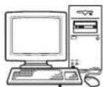

DICOM LAN network

Modality Image diagnosis equipment and so on
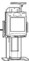
Modality Image diagnosis equipment and so on

Modality Image diagnosis equipment and so on

UP-DF760

Location and Function of Parts and Controls
For details, refer to the pages given in parentheses.
Front panel

Rear panel

1 Liquid Crystal Display (LCD) (11)
Displays information about the status of the unit (standby, errors, etc.) and shows menus. During menu operation, the display shows the respective menu. When an error has occurred, the display shows the error message.
2 ALARM indicator (43)
Lights in orange when film sheets have been used up in both film trays, film sheet jams occur, or other problems occur.
3 Front cover (47)
Open when you clean the thermal head and filters, and when you replace the cleaning roller with a new one. Also open this when you remove a jammed film sheet.
4TOP cover (47)
Open when removing a jammed film sheet.
5 Ventilation holes
There is a built-in fan to prevent the thermal head from overheating.
6ELECT TRAY button
Push this button to pull film tray 1 out. This button is activated when the power is on and all covers are closed.
7EJECT TRAY button
Push this button to pull film tray 2 out. This button is activated when the power is on and all covers are closed.
8Film output slot 1
Printed film sheets (film sizes 8 × 10 (about 202 × 253 mm), 10 × 12 (about 253 × 304 mm), 11 × 14 (about 279 × 355 mm)) are ejected here.
9 Output tray (14)
Printed film sheets (film sizes 8 × 10 (about 202 × 253 mm), 10 × 12 (about 253 × 304 mm), 11 × 14 (about 279 × 355 mm)) are ejected onto this tray, which also serves to prevent sheets from dropping. The tray size must match the film size. If a change is necessary, please contact your Sony dealer to have the procedure performed.
10 Front cover lock lever
Used to open the front cover.
11Film output slot 2
Printed film sheets (film sizes 14 × 17 (about 353 × 430 mm), 11 × 14 (about 279 × 355 mm)) are ejected here. In the factory default condition, only film size 14 × 17 (about 353 × 430 mm) is supported. To eject film size 11 × 14 (about 279 × 355 mm) film sheets, the output tray size must be changed. If a change is necessary, please contact your Sony dealer to have the procedure performed.
12Film tray 1 (18)
In the factory default condition, this is set for film size 14 × 17 (about 353 × 430 mm). To use films of other sizes, contact your Sony dealer to have the tray size changed. Printed film sheets are ejected onto this tray.
13Film tray 2 (18)
In the factory default condition, this is set for film size 8 × 10 (about 202 × 253 mm). To use films of other sizes, contact your Sony dealer to have the tray size changed.
14ON/STANDBY switch/indicator (15)
The indicator is turned off when the main power of the unit is off, and the indicator lights up in orange when the main power of the unit is on.
To turn on the unit, press the switch when the indicator lights up in orange. The indicator changes to green when the unit is turned on.
To turn off the unit, press the switch. The indicator blinks, then lights up in orange after the unit is turned off.
By pressing the switch again while the indicator is blinking, the power turns back on.
Note
If the I/O main power switch on the rear panel is not set to the on (I) side, the power is not on even though the ON/STANDBY switch on the front panel is pressed.
15 EXEC button (28)
Use this button in menu operations.
16 ⇔, ⇔, ⇔, ⇔ (Cursor control) buttons (28)
Press these buttons to increase or decrease the setting values. Also press these buttons to select menu items.
17 MENU button (28)
Press this button to display menus on the LCD display. Also press this button to return to the normal window.
18Rear cover 1 (47)
Open this cover when removing jammed film sheets loaded in film tray 1.
19Rear cover 2 (47)
Open this cover when removing jammed film sheets loaded in film tray 2.
20 Network connector (RJ-45 modular jack) (15)
Used to connect to a LAN.
Caution
For safety, do not connect the connector to peripheral device wiring that might have excessive voltage.
Follow the instructions for use for this port.
21 Cable stopper
Secures the network cable to prevent it from being disconnected.
22\~AC IN connector (15)
Use the proper power cord for your local power supply (not supplied). Refer to “Warning on power connection” on page 7.
23 I/O main power switch (15, 17)
Switches the main power of the unit on or off.
24 Equipotential ground terminal connector
Used to connect to a ground (equipotential) plug to bring the various parts of the system to the same potential.
Refer to “Important safeguards/notices for use in the medical environments” on page 2.
LCD panel indication
The LCD panel of the unit displays various standby and error information as well as menu screens.
Standard screen (during standby)
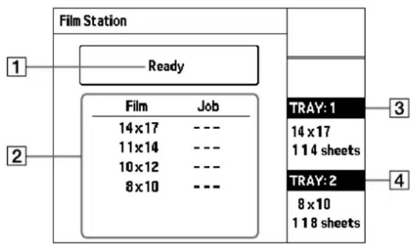
1Status
Shows the current status of the printer.
2 Job information
Shows information about jobs sent to the printer, sorted by film size.
③Film tray 1 information
Shows the size of film and remaining number of sheets loaded in the upper film tray 1.
4 Film tray 2 information
Shows the size of film and remaining number of sheets loaded in the lower film tray 2.

Standard screen (when error has occurred)
![Film Station 1 2 [1]Set Film TRAY: 1 Set Film 3 TRAY: 2 Set Film 4](/content/2026/08/1617581/images/8c432f7b35715974bef2f363159605c387eb5a054a5f2c36fdc46a265509de68.jpg)
1 Error countermeasure illustration
Shows an illustration indicating the appropriate step to take for correcting the error that has occurred.
2 Error message
For details, see "Error Messages" (page 43).
③ Film tray 1 information
Shows the status of the upper film tray 1.
4 Film tray 2 information
Shows the status of the lower film tray 2.
Menu screen (Menu item list)
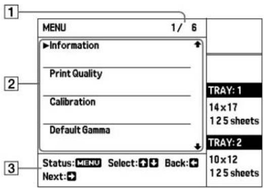
1 Menu item number
The left digit indicates the number of the menu item selected with the cursor (▶). The right digit indicates the total number of menu items, including those that are currently not shown on the menu screen.
2Menu item
Shows a list of menu items and the cursor (▶) for selecting an item.
③Operation guidance
Shows possible actions for the current menu screen.
Menu screen (Settings screen)

1 Menu item name
Shows the name of the currently displayed item. The “>” before the item name indicates the current menu level.
2 Setting value
A list of possible values for the currently displayed setting item is shown. The cursor (▶) for selecting a value is also shown.
The previously set value is marked by a “●” symbol.
Preparation
Supplied Accessories
The unit is packed together with the following accessories. Check that nothing is missing from your package.
Output tray (1)

Cleaning kit (1)
Output tray stopper (1)
Film tray size adapter kit (1)
Instructions for Use (1)
Notes
- Retain the original carton and packing materials in case you have to transport the unit in the future.
- The output tray stopper and film tray size adapter kit will be required when the tray size is to be changed later. Store these items carefully.
Removing the Packing Materials
Before using the unit for the first time, be sure to remove the packing materials from inside the unit and film trays.
1 Open the top cover and inner cover (page 48), and remove the packing materials from inside the unit.
2 Pull out film tray 1, and remove the tray cover.
3 Remove the packing material, and place the cover back onto the tray.
4 Repeat steps 2 and 3 for film tray 2.
5 Place film trays 1 and 2 back into the unit.
Notes
- Failure to remove the packing materials from the unit will result in film jams.
- If you turn on the unit without removing the packing materials from inside the film trays, a “Check Tray” error will occur.
Assembly
Insert the supplied output tray into the unit. Holding both sides of the output tray with both hands, insert it all the way into the unit.

Preparation

Be sure to fully insert the projecting parts of the output tray into the corresponding holes of the unit.

Notes
- The size of the supplied output tray must be adjusted to match the film tray size. Please contact your Sony dealer to have the size adjustment performed.
- Be sure to insert the output tray all the way into the unit. If you do not, the error message "Set Output Tray" appears when you start printing and the printer will not continue the printing operation.
Output tray size
The combinations for film size and corresponding output tray size are as listed below.
Large Size
This is the factory default setting.

| Film size combinations Output tray stopper | |
| 8 × 10\ 8 × 10 | Required |
| 8 × 10\ 10 × 12 | |
| 8 × 10\ 14 × 17 | |
| 10 × 12\ 10 × 12 | |
| 10 × 12\ 14 × 17 | |
| 11 × 14\ 11 × 14 | Not required 11 × 14\ 14 × 17 |
| 14 × 17\ 14 × 17 | |
Note
If you use film size 11 × 14 (about 279 × 355 mm) while the output tray stopper is mounted, a film jam will occur.
Small Size
Please contact your Sony dealer to have the size changed to this setting.
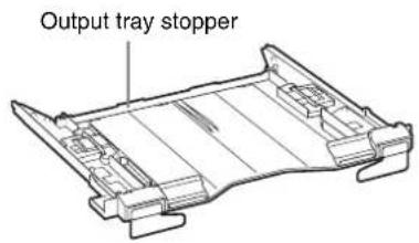
Film size combinations Output tray stopper
| 8 × 10 11 × 14 | . \\ \ Required |
| 10 × 12 11 × 14 |
Placing the Unit
This unit cannot be placed vertically.
To maintain performance, adequate space is needed for ventilation. Also, to remove jammed film, space of about 8 cm (3 1/4 inches) towards the back and about 26 cm (10 1/4 inches) over the top of the unit are required.

Caution
If you place the unit without providing adequate space around it, heat may build up inside the unit and result in fire or damage. Be sure to provide at least 8 cm (3 1/4 inches) of space around the unit.
Connections
Connect the unit to a LAN.
Notes
- Turn off the power of each device before attempting to make any connections.
- Connect the AC power cord last.
- Before connecting to the LAN, be sure to set up the required IP address and sub-net mask.
For detailed information, consult the system administrator.

Notes on the LAN cable
- Be sure to use a LAN cable of less than 30 m (98 feet 5 1/4 inches) in length, and rated more than category 5e.
- It is recommended that you use a shielded cable.
Turning the Unit On or Off
Turn the printer power on after you connect the AC power cord.
Turning the main power of the unit on
Set the I/O main power switch to the on (I) side. The main power turns on, and the ON/STANDBY indicator on the front panel lights up in orange.


Note
The unit is not turned on even if the I/O main power switch of the unit is turned to the on (1) side.
Turning the unit on
Use the ⏻ON/STANDBY switch located on the front of the unit to turn the unit on during daily use.

1 Press the ⏻ON/STANDBY switch to set the unit to on.
The ⓍON/STANDBY indicator lights up in green, and the “Film Station” logo is shown on the LCD panel. Then the following screen appears.
![graph TD A["Initializing"] --> B["TRAY: 1"] A --> C["TRAY: 2"]](/content/2026/08/1617581/images/dd97a012594594039fa30d928551370a726dc77cf949ec89f0419df9e47f2197.jpg)
After a few minutes, the following message should appear.
When you use the unit for the first time
![Film Station [1]Set Film TRAY: 1 Set Film TRAY: 2 Set Film](/content/2026/08/1617581/images/01a9db4ccb206194a79705bed60c2f4662103eb1d96a11440f1dc05de79acf09.jpg)
The above message should appear when you use the unit for the first time, because the film sheets are not loaded in the film trays of the unit.
For detailed information on how to load the film sheet, see “Loading Film Sheets” on page 18.
When you already use the unit

When the above message appears, the unit is ready to print.
Note
If the I/O main power switch located on the rear panel is not set to the on (I) side, the power is not on even though the ON/STANDBY switch located on the front panel is set to on.
When the I/O main power switch is set to the on (I) side, the ON/STANDBY indicator on the front panel lights up in orange.
Turning the unit off
Use the ⏻ON/STANDBY switch located on the front of the unit to turn the unit off during daily use.
1 Press the ⏻ON/STANDBY switch.
The ⏻ON/STANDBY indicator blinks and the message “Please Wait” appears on the LCD. Then the message disappears, the unit turns off and the ⏻ON/STANDBY indicator lights up in orange.
When you do not intend to use the printer for a long time
Turn the printer off as follows.
1 Press the ⏻ON/STANDBY switch. The ⏻ON/STANDBY indicator blinks and the message “Please Wait” appears on the LCD. Then the message disappears, the unit turns off and the ⏻ON/STANDBY indicator lights up in orange.
2 Set the I/O main power switch located on the rear of the unit to the off (O) side. The main power turns off, and the ON/STANDBY indicator on the front panel turns off.
Operation
Loading Film Sheets
Recommended Film Sheets
The following packs of blue thermal film sheets are made especially for the UP-DF760.
Blue Thermal Film UPT-517BL
Contains blue thermal transparent film sheets.
125 sheets of size 14 × 17 film (about 353 × 430 mm)
Blue Thermal Film UPT-514BL
Contains blue thermal transparent film sheets.
125 sheets of size 11 × 14 film (about 279 × 355 mm)
Blue Thermal Film UPT-512BL
Contains blue thermal transparent film sheets.
125 sheets of size 10 × 12 film (about 253 × 304 mm)
Blue Thermal Film UPT-510BL
Contains blue thermal transparent film sheets.
125 sheets of size 8 × 10 film (about 202 × 253 mm)
Note
Be sure to use film sheets made expressly for the UP-DF760. If you use other film sheets, the quality of the printout cannot be guaranteed. Use of another type of film sheets may also cause malfunction of the unit.
Loading Film Sheets
About the film tray
The printer is equipped with two film trays.
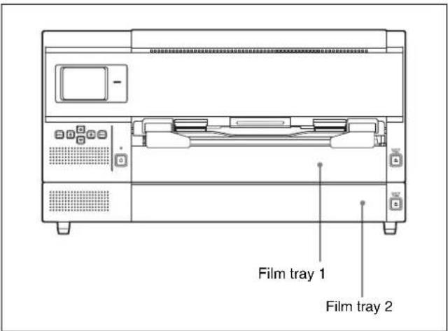
Film tray 1
In the factory default condition, this is set for film size 14 × 17 (about 353 × 430 mm). This is also used for the output tray.
Film tray 2
In the factory default condition, this is set for film size 8 × 10 (about 202 × 253 mm).
To use films of other sizes, contact your Sony dealer to have the tray size changed.
Confirming the remaining amount of film
The LCD allows you to confirm the size and remaining amount of film sheets.
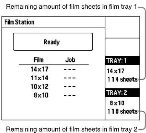

When the film sheets loaded in either film tray 1 or film tray 2 have been used up:
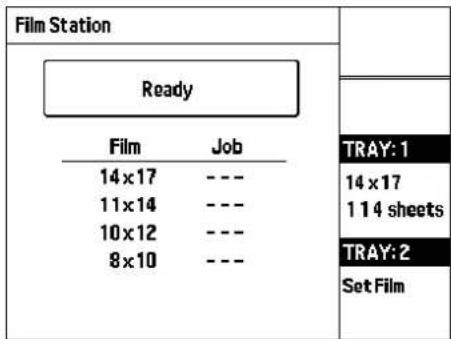
On the row corresponding to the tray where film sheets have been used up, the message "Set Film" is displayed.
When the film sheets loaded in both trays have been used up:
![Film Station [1]Set Film TRAY: 1 Set Film TRAY: 2 Set Film](/content/2026/08/1617581/images/0d98c3902de62f2f8f1699be3f359657410ee3961c766b515c3b7de918d9e62c.jpg)
The message “Set Film” is displayed on both rows. The ALARM indicator lights in orange.
Loading film sheets
Proceed as follows to load film sheets.
The following explains how to load film sheets using film tray 1 as an example. Load film sheets in the lower tray in the same way as you do for the upper tray.
Notes
- Hold the film using the damp-proof bag. Do not touch the film directly. Dust, finger prints, or sweat are likely to cause unsatisfactory printing.
- Hold both sides of the film tray and tray cover tightly when handling the film tray.
1 Push the EJECT TRAY button for film tray 1 on the front panel.
Film tray 1 is partially ejected.

Notes
- You can load film sheets without pulling out the film tray completely out. However, if you want to pull out it completely, hold both sides of the film tray and film tray cover firmly.
- The film tray cannot be ejected during printing or when the covers are open.
- Even when film sheets have run out in the middle of continuous printing, you can load new film sheets in the vacant film tray. (See page 25.)

2 Open the film tray cover by putting your fingers in the grooves on both sides of film tray 1, and pulling it upward in the direction of the arrow.
Pull it upward in the direction of the arrow, putting your fingers in the grooves.

Note
If the old printing surface protection sheet remains in film tray 1, remove it.
3 Remove the damp-proof bag from the carton.
4 Open the damp-proof bag by tearing at the pre-cut tabs.

Note
Remove the seal after loading the film into film tray 1. If you remove it before loading, the film sheets may slip and drop.

5
Hold the damp-proof bag with both hands so that the opened side faces toward the inner side of the tray and place film sheets in the film tray so that the printing surface faces down, with the printing surface protection sheet on the bottom.
Blue thermal film with printing surface facing down

Place the film sheets with the printing surface facing down and the printing surface protection sheet on the bottom.

An IC tag is attached to the printing surface protection sheet. Be careful not to damage the IC tag or give it a shock.
Notes
- When handling the film sheets, do not touch the printing surface of the film sheet. Dust, finger prints, or sweat are likely to cause unsatisfactory printing.
- Load the film sheets so that they lay flat in the film tray. If the film sheets are curled, they will overflow the film tray and the printing position may shift. Also, it may cause film sheet jamming.
- If you place the film sheets in the film tray with their printing surface facing up by mistake, it is recommended that you clean the thermal head with the cleaning kit (supplied). See “Cleaning the thermal head” (on page 39).
- Do not add film sheets halfway through one bag of film sheets. The reason for this is because the unit counts the remaining film sheets using the IC tag on the printing protection sheet on the bottom of the pile of sheets.
6
Remove the seal used to secure the film sheets in the package from the film sheets placed in the film tray.
①Remove the sticky part of the seal, pulling the blank part of the seal toward you.

②Pull the blank portion of the seal out of the film tray, and remove the seal from the film tray completely.

Note
If the seal is caught by the cover of the film tray, or is left curled in the film tray, this may cause film sheet jamming. Be sure to remove the seal completely from the film tray.


③Close the film tray cover.

7 Insert film tray 1.

After a few seconds, the film tray is locked and the following message appears on the LCD.

To calibrate the printing density
We recommend calibrating the printing density of the loaded film by referring to “Calibrating the Printing Density” on page 31.
Notes
- Be sure to insert film tray 1 all the way into the unit until it stops. When the film tray is not inserted completely and the film sheets are not loaded correctly, the following message appears on the LCD.

- If you try to insert the film tray into the wrong film tray side, you cannot do so because the stopper prohibits you from inserting the tray all the way in.
If the cover of the film tray comes off
Remove the film tray and re-attach the cover.
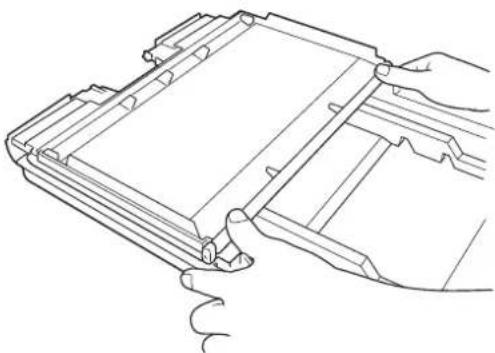
When using size 8 × 10 (about 202 × 253 mm) film Insert the film sheets securely as the printing surface protection sheet passes over the stopper located in the film tray.

Stopper
If you can see the film sheets in the film tray If you slant the film tray, film sheets may move to the outlet of the film tray. This may cause film jamming. In such a case, put the film sheets back inside the film tray by pushing them with your finger, as shown below.

Notes on storing film sheets
- To store a half-used film sheets for a long time, remove them from the film tray, and store them in a cool, dark place in the sealed damp-proof bag.
- Store unopened packages in a cool, dark place.
Printing
Before printing
- Ensure that the unit is properly connected to the LAN. (Page 15)
- Ensure that the film sheets are properly loaded in the film tray. (Page 18)

1 Press the ⏻ON/STANDBY switch to turn the unit on. After turning on the power, the message below should appear as shown on the LCD.
![graph TD A["Initializing"] --> B["TRAY: 1"] A --> C["TRAY: 2"]](/content/2026/08/1617581/images/b1d73fe22b2cc4c5c5280b7c821d5c9f3e1a983630b3553861237e47bcb2d76a.jpg)
After a few minutes, the message should appear as shown here.
When the size and remaining amount of film sheets are displayed, the printer is ready to print.

2 Send the image data from the modality. The message changes on the LCD as the unit status changes:
| Message | Printer status |
| Processing | The image data is being processed. |
| Reserved | |
| Printing | The printer is printing. |
During printing, messages indicating the printer status are shown on the LCD panel, along with information about jobs sent to the printer, sorted by media.
Example: Image sent to film tray 1 (size 14 × 17 (about 353 × 430 mm) film)
During image processing, the following indication appears on the LCD panel.
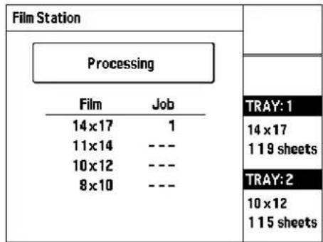
When image data processing is completed, printing starts. The LCD panel indication changes as follows.

While the "Printing" message is shown, the remaining film sheet count is decremented by 1.
After about 60 seconds, the first printed image will be ejected from the output tray.
When all images have been printed, the LCD panel returns to the standard screen.
Notes
- During printing, do not open the covers.
- Depending on the combination of film sizes in trays 1 and 2 and the output tray type, the indication "OutputTrayMismatch" may appear. In such a case, the output tray size must be changed. Please contact your Sony dealer to have the size adjustment performed.
- To prevent film jamming, do not allow more than 30 printouts to remain on the film output slot. Depending on usage conditions, the message "Remove Prints" may appear or the indication "Rmv Prt" may be shown in the film tray status field even if fewer than 30 printouts have accumulated. Also, ejected printouts may drop from the output tray.
- Do not put a printout which has been removed from the film output slot back inside the film output slot. This may cause film jamming.
If the unit does not print
When an error message is displayed on the LCD, the unit does not print. Take remedies according to the information given in “Messages” (on page 43).
When the film sheets run out during printing
The message “Set Film” appears on the row of the LCD corresponding to the film tray where the film sheets have run out.
1 Press the EJECT TRAY button corresponding to the film tray from which the film sheets have run out. The ALARM indicator blinks in orange. When the film sheet currently printing is completed, the unit stops printing, and the film tray is partially ejected.
2 Load new film sheets. For detailed information on how to load the film sheets, see “Loading Film Sheets” on page 18. The unit restarts printing when the film tray is fully inserted.
Note
When the message “Set Film” or “Rmv Prt” appears on a row of the LCD, the unit stops printing from the corresponding film tray. However, the unit will continue printing in the other film tray. In this case, printing order may change.
Notes on storing your printouts
- Do not leave the printouts in direct sunlight or bright room light. Store in a cool, low-humidity place (under 25°C ( 77°F )). We recommend storing the printouts in a polypropylene pouch in a cabinet.
- Do not allow water or any volatile organic solvent such as alcohol or benzine to come in contact with the printouts. This can cause fading of the printouts. If the printouts come in contact with such liquid, wipe them off quickly.
- Adhesives from cellophane tape or PVC will cause fading of the printout. Be careful when storing printouts.
- Do not stack the printouts on or under a freshly developed diazo copy sheet as this could cause the film sheets to fade or stick to each other.
Adjustment
Adjustment and Setting Using a Menu
You can set the following items using the relevant menu:
- Confirming information (Information) (page 28)
- Adjusting the print quality (Print Quality) (page 28)
• Calibration (Calibration) (page 31) - Selecting a gamma curve (Default Gamma) (page 33)
- Settings for network and LCD panel (System Settings) (page 34)
- Printing of print test pattern (Test Print) (page 36)
Notes
- The next printout will be printed with the values most recently set. You cannot adjust the setting during printing. Once you have adjusted and stored the settings, the printer operates according to those settings until their values are modified.
- If no button is pressed for about 20 seconds after pressing the MENU button, the indication automatically returns to the standard screen. However, during IP address setting and during print image adjustment, the indication automatically returns to the standard screen if no button is pressed for about 30 minutes. In this case, all adjustments made up to that point (input of IP address values or print image adjustment settings) will be lost.
Menu Configuration
The ⇔ and buttons serve to move within the same level.
The ⇔ and ⇒ buttons serve to move up and down among levels. (Except in some cases)
In any level, pressing the MENU button will bring up the standard screen.
![graph TD A["Ready"] --> B["Information"] B --> C["IP Address"] B --> D["Total Prints"] A --> E["Print Quality"] E --> F["Gamma 1 - 20"] F --> G["Sharpness:"] F --> H["Pattern Print"] F --> I["Point 95%:"] F --> J["Point 5%:"] F --> K["Save Gamma"] A --> L["Calibration"] L --> M["Full Range Calibrati…](/content/2026/08/1617581/images/11fed4bde76203877d63759950985f56affe5da9b58faebe6931e97d136cf0ce.jpg)

Menu Operation
Confirming Information
You can confirm the IP address and the total number of prints made since you started the unit.

1 Press the MENU button to bring up the menu screen.
2 Press the ⇔ or ⇔ button to move the cursor to "Information," and then press the ⇔ button. The IP address of the unit and the total number of prints since starting to use the unit are shown. Press the MENU button to close the menu screen and return to the standard screen.

The IP address setting cannot be changed here. To change the IP address, use the System Settings menu. For details, refer to "Setup" described in the "Setup Manual" section of this document.
The total number of prints since starting to use the unit is useful to estimate when regular maintenance such as replacing the cleaning roller, cleaning the thermal head, etc. is necessary. For details, see “Maintenance” (on page 38).
Adjusting the Print Quality
You can adjust the following items for each gamma curve. The adjusted settings are stored for each blue thermal film gamma curve.
- Sharpness of the printout
You can adjust the sharpness among 17 levels between 1 and 16, including OFF. - Tone of printouts
You can adjust the high tone (dark area of the images) and the low tone (light areas of images).
Notes
- You cannot adjust the gamma curve itself using the menu. To change the gamma curve, contact your Sony dealer.
- To make a printout of the pattern print to be used for adjusting the tone of printouts in this section correctly, be sure to perform the full range calibration for each type of blue thermal film before starting the adjustments described here.
For detailed information on the full range calibration, see "To perform calibration of each blue thermal film" on page 31.

1 Press the MENU button to bring up the menu screen.
2 Press the ⇧ or ⇧ button to move the cursor to "Print Quality," and then press the ⇧ button. The unit enters the gamma selection mode.
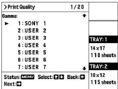
3 Press the ⇧ or ⇧ button to move the cursor to the gamma curve for which you want to make image adjustments, and then press the ⇧ button. The unit enters the image adjustment mode.
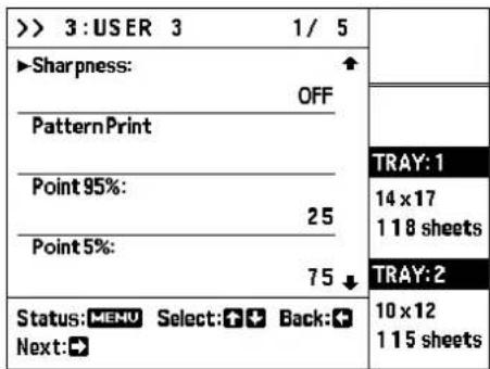
4 Press the ⇒ button. The unit enters the sharpness adjustment mode.
5 Select the desired level by pressing the ↗ or ▽ button.

The sharpness setting range is 1 - 16 or OFF. The default setting is OFF.
Pressing the ⬆ button increases the sharpness value, emphasizing the outline of the print image.
Pressing the ↘ button decreases the sharpness value, making the outline of the print image less distinct.
After the sharpness has been adjusted, print a density pattern and adjust the value while checking the printed result.
6 Press the EXEC button. The sharpness setting is stored, and the unit enters the test pattern print mode.
![> 3:USER 3 2/2 PatternPrint [1]:14×17 ►[2]:10×12 TRAY: 1 14×17 118 sheets TRAY:2 Status:MENU Select:Back: Print:EXEC 10×12 115 sheets](/content/2026/08/1617581/images/361384f23cfafce54ab4ff4101af6024e7542168973cab3b94d27adc06a09356.jpg)
7 Press the ⇔ or button to move the cursor to the tray containing the blue thermal film to be used for printing the density pattern.
![> 3:USER 3 1/2 PatternPrint ►[1]:14 x 17 [2]:10 x 12 TRAY: 1 14 x 17 1 18 sheets TRAY:2 Status:MENU Select:Back: Print:EXEC 10 x 12 1 15 sheets](/content/2026/08/1617581/images/4a5a59e766add45b029778a9cc0f6fdf53ce18a2b2f6e93b803fa405da755437.jpg)
8 Press the EXEC button to make a printout of the pattern print. The unit starts the printing of the tone pattern.


When the density pattern printing is completed, the following screen appears on the LCD panel. (If the screen does not appear, press the ⇔ button to return to step 3, press the ⇔ or ⇌ button to move the cursor to "Point 95%", and then press the ⇌ button.)

While checking the density pattern print, perform the following steps to adjust the low tone and high tone.
9
Adjust the low tone.
Select the desired lightest area of the image.
①Select the number of the desired low tone area (light area data 95%). The low tone range is between 01 and 49 (10, 20, 30 and 40 are skipped).
Chart of the low tone range


② Display the selected number by pressing the ♠ or ♦ button.
To reset to the default setting of the low tone range
Display 25.
10 Press the EXEC button.
The low tone setting is stored, and the following screen appears on the LCD panel.
(If the screen does not appear, press the ⇔ button to return to step 3, press the ⇔ or button to move the cursor to "Point 5% ", and then press the ⇔ button.)
| >> 3:USER 3 1/1 | |
| Point 5%: 75 | |
| TRAY:1 14 x 17 117 sheets | |
| TRAY:2 | |
| Status:MENU UP:↑ Down:↓ Back: Set: EXEC | 10 x 12 115 sheets |
11 Adjust the high tone.
Select the desired darkest area of the image.
①Select the number of the desired high tone area (dark area data 5%). The high tone range is between 51 and 99 (60, 70, 80 and 90 are skipped).
Chart of the high tone range


② Display the selected number by pressing the ⇧ or ⇧ button.
To reset to the default setting of the high tone range
Display 75.
12 Display the "Save Gamma" by pressing the EXEC button.

13 Press the EXEC button.
The gamma curve adjustment values selected in step 3 are stored and will be effective from the next printing operation.
The following screen appears on the LCD panel. Press the MENU button to close the menu screen and return to the standard screen.

Calibrating the Printing Density
The unit automatically calibrates the printing density according to the density curve set.
Perform calibration for each type of blue thermal film separately.
It is recommended to perform this operation when new film was inserted.
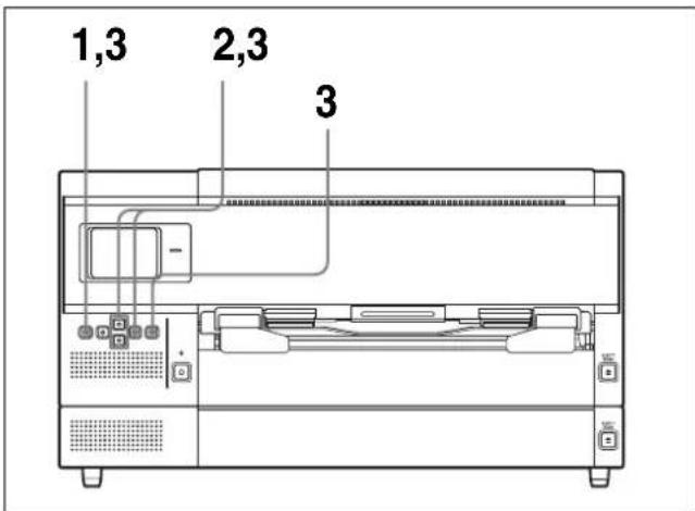
1 Press the MENU button to bring up the menu screen.
2 Press the ⇔ or ⇔ button to move the cursor to "Calibration," and then press the ⇔ button.

3 Select the desired calibration type by pressing the or button.
To perform calibration of each blue thermal film
① Press the ⇔ or button to move the cursor to "Full Range Calibration," and then press the ⇔ button.


② Press the ⇔ or button to select the tray containing the blue thermal film for which the calibration is to be carried out.
| > Calibration 1/ 2 | |
| Full Range Calibration▶ [1]:14×17[2]:10×12 | |
| TRAY: 1 | |
| 14×171 1 7 sheets | |
| TRAY: 2 | |
| Status: MENU Select: 📋 Back: Print: EXEC | 10×121 1 5 sheets |
③Press the EXEC button.
Calibration printing starts, and density is automatically adjusted during printing. The result of automatic calibration will be effective from the next printing operation.
④Press the MENU button.
The menu screen closes and the unit returns to the standard screen.
To perform calibration of another blue thermal film
Repeat step 1 to 3.
To make an automatic calibration
The unit can perform a calibration for the first film each time you load new film sheets into the film tray 1 or film tray 2.
① Press the ⇧ or ⇧ buttons to move the cursor to "Auto Calibration," and then press the ⇧ button.
| > Calibration 2/3 | |
| Full Range Calibration | |
| ▶Auto Calibration: OFF | |
| Calibration Reset | |
| TRAY:1 | |
| 14 x 17 | |
| 117 sheets | |
| TRAY:2 | |
| Status:MENU Select:Back:Next:→ | 10 x 12 |
| 115 sheets |
② Press the ⇔ or button to move the cursor to "ON."
The setting next to the cursor becomes effective.
| >Calibration 1/2 |
| Auto Calibration: ▶ ON ◆OFF |
Item Setting
| ON The printer performs the calibration automatically using the first film sheet each time you load new film sheets into film tray 1 or film tray 2. |
| OFF The printer does not perform the automatic calibration (retains the factory setting). |
③Press the MENU button.
The menu screen closes and the unit returns to the standard screen.
To reset to the default status
To cancel density adjustment by "Full Range Calibration" and reset density to the default, proceed as follows.
① Press the ⇔ or ⇔ button to move the cursor to "Calibration Reset," and press the ⇔ button.
| >Calibration 3/3 | |
| Full Range Calibration | |
| Auto Calibration: OFF | |
| >Calibration Reset | TRAY: 1 |
| 14 x 17 | |
| 117 sheets | |
| TRAY: 2 | |
| Status: MENU Select: ➕ ➕ Back: ➕ Next: ➕ | 10 x 12 |
| 115 sheets |
② Press the ⇔ or button to move the cursor to the blue thermal film for which you want to restore the default setting.
| >Calibration 1/2 |
| Calibration Reset▶[1]:14×17[2]:10×12Reset? |
③Press the EXEC button.
The density setting of the selected blue thermal film is reset to the default. The LCD panel indication changes as follows.
| >Calibration 1/2 | |
| Calibration Reset▶[1]:14×17[2]:10×12OK | TRAY:114×17117 sheetsTRAY:210×12115 sheets |
| Status:MENUBack:+ |
④Press the MENU button.
The menu screen closes and the unit returns to the standard screen.
To reset another type of blue thermal film to the default status
Repeat steps ① to ④.
Selecting a Gamma Curve
If the gamma curve has not been specified at the modality side, the gamma curve selected at the unit will be used for printing. In this case, the gamma curve can be selected separately for each blue thermal film.

1 Press the MENU button to bring up the menu screen.
2 Press the or button to move the cursor to "Default Gamma," and press the button.
A screen for specifying the blue thermal film type appears.
| >Default Gamma 1/4 | |
| ▶14x17:1:SONY 1 | |
| 11x14:1:SONY 1 | |
| 10x12:1:SONY 1 | |
| 8x10:1:SONY 1 | |
| Status:MENU Select:Back:Next: | TRAY:114 x 17117 sheetsTRAY:210 x 12115 sheets |

3 Press the ⇧ or ⇧ button to select the blue thermal film for which you want to change the gamma curve, and press the ⇧ button.
A screen for selecting the gamma curve appears.
The following explanation shows how to change the gamma curve for size 14 × 17 (about 353 × 430 mm) film.

4 Press the ⇔ or button to move the cursor to the desired gamma curve.
The gamma curve for SONY 1 has been pre-set, you cannot change these settings.
The gamma curves for USER 2 to USER 20 can be set to the desired value. For advice on the settings, contact your Sony dealer.
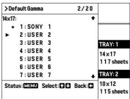
Gamma curve Setting
| SONY 1 Default setting (standard and basic curve) |
| USER 2 to USER 5 Each gamma curve has been preset to the proper settings based on the SONY 1 gamma curve. |
| USER 6 to USER 20 Not preset. For advice on settings, contact your Sony dealer. If you select one of these gamma curves, USER 6 to USER 20, before setting, the same setting as that of SONY 1 is applied. |
5 Press the ⇔ button.
The unit returns to the screen of step 2 (blue thermal film type selection screen).
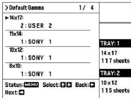
6 Repeat steps 3 - 6 to change the gamma curve for the remaining blue thermal film types.
7 Press the MENU button.
The menu screen closes and the unit returns to the standard screen.
Making Network and LCD Panel Settings
This section explains how to make network settings, and how to adjust various LCD panel settings including backlight operation, brightness, contrast, and display language.
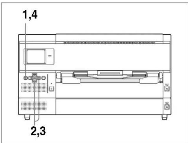
1 Press the MENU button to bring up the menu screen.
2 Press the ⇧ or ⇧ button to move the cursor to "System Settings," and press the ⇧ button. The System Settings screen appears.
| > System Settings 1/5 | |
| ▶Network Setting ↑ | |
| LCD Back Light: AUTO | |
| LCD Brightness: 10 | |
| LCD Contrast: AUTO ↓ | |
| Status: MENU Select: 📋Back: Next: ➔ |
3 Press the ⇧ or ⇧ button to move the cursor to the desired setting item, and press the ⇌ button. You can now make settings for the respective items.
Network Setting
You can specify the IP address, subnet mask, gateway address, and other network settings. For details, refer to “Setting the IP Address” described in the “Setup Manual” section of this document.
Note
If network settings are changed by mistake to unsuitable values, the unit will no longer be accessible via the network. Network settings should only be changed by the system administrator. If settings need to be changed, contact your Sony dealer.
LCD BackLight
| >System Settings 3/3 |
| LCD Back Light:OFFON▶♦AUTO |
Controls operation of the display backlight. Press the ⇔ or ⇔ button to move the cursor to the desired setting.
| Setting Description |
| OFF Backlight is always off. |
| ON Backlight is always on. |
| AUTO Backlight is turned on when any buttonis operated, and is turned offautomatically when no button has beenoperated for about 20 seconds. (Factorydefault setting) |
LCD Brightness
| >System Settings 1/ 1 | |
| LCD Brightness: 11 | |
| TRAY: 1 | |
| 14 x 17117 sheets | |
| TRAY: 2 | |
| Status: MENU UP: ↑ Down: ↓ Back: + | 10 x 12115 sheets |
A value indicating the current LCD panel brightness setting is shown on the menu screen. The brightness setting range is 1 - 20.
Pressing the ↗ button increases the value and makes the LCD panel brighter.
Pressing the ◇ button decreases the value and makes the LCD panel darker.
LCD Contrast
| >System Settings 1/ 1 | |
| LCD Contrast: AUTO | |
| TRAY: 1 | |
| 14 x 17 | |
| 1 1 7 sheets | |
| TRAY: 2 | |
| Status: MENU UP: ↑ Down: ↓ Back: + | 10 x 12 |
| 1 1 5 sheets |
A value indicating the current LCD panel contrast setting is shown on the menu screen. The contrast setting range is 1 - 20.
Pressing the ⬆ button increases the value and increases the contrast of the LCD panel.
Pressing the ↘ button decreases the value and decreases the contrast of the LCD panel.
If you press the ♘ or ♦ button to select the AUTO setting, the display contrast is automatically adjusted according to the ambient temperature.


Language
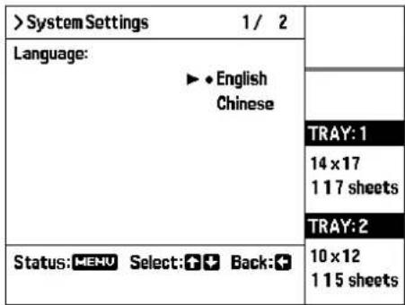
Press the or button to move the cursor to the desired language setting.
The change in language setting becomes effective the next time power to the unit is turned on. To make the change immediately active, power down the unit and then turn power on again.
4 When the setting is complete, press the MENU button.
The menu screen closes and the unit returns to the standard screen.
Test Print
By performing the following steps, you can print out a special pattern for verifying correct operation.

1 Press the MENU button to bring up the menu screen.
2 Press the ⇧ or ⇧ button to move the cursor to "Test Print," and press the ⇧ button.
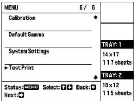
A screen for selecting the pattern appears.

3 Press the ⇒ button.

A screen to start printing the test image pattern appears.
4 Press the ⇧ or ⇧ button to move the cursor to the film size that you want to use.
![>TestPrint 1/2 SMPTE ►[1]:14 x 17 [2]:10 x 12 TRAY:1 14 x 17 1 17 sheets TRAY:2 Status:MENU Select:Back:+ Print:EXEC 10 x 12 1 15 sheets](/content/2026/08/1617581/images/9142c6ef15cd4941d8f6f48ff36555ef13ee3da508e5d1e9cafb1f869565fcf3.jpg)
5 Press the EXEC button. The test image pattern is printed. When printing is completed, the following screen appears.

Press the MENU button to close the menu screen and return to the standard screen.
Other Settings
The following settings can be changed, but not by using the menu. However, you cannot change the following settings by yourself. To change the following settings, contact your Sony dealer.
| Item Default setting | |
| Making the buzzer sound when error messages such as Set Film, Remove Prints and so on, are displayed. | Off (No buzzer) |
| Reversing the printouts horizontally. | Off (Do not reverse the printouts.) |
| Attaching the L and R marks on each printout. | Off (Do not attach L and R marks.) |
| Printing caption on the top and bottom of the black frame. | On (Captions are printed. However, if the content of the caption is not configured, the captions will not be printed.) |
| Changing the gamma curve of USER 2 to USER 20. | For USER 2 to USER 5: Each gamma curve has been preset to the proper settings based on the SONY 1 gamma curve. For USER 6 to USER 20: The same setting as the one of SONY 1 is applied. |
Miscellaneous
Precautions
Safety
- Operate the unit using the power source specified in "Specifications" (on page 41).
- Be careful not to damage the AC power cord by placing or dropping heavy objects on it; it is dangerous to use the unit with a damaged AC power cord.
- If you do not intend to use the unit for a long time, disconnect the AC power cord.
- Unplug the AC power cord by grasping the plug, not the cable itself.
- Do not disassemble the unit.
- Do not remove the cabinet. There is a danger of electric shock from the internal parts.
- Be careful not to spill water or other liquids on the unit, or to allow combustible or metallic material to enter the cabinet. If used with foreign matter in the cabinet, the unit is liable to fail, or present a risk of fire or electric shock.
- If the unit malfunctions or if a foreign body falls into the cabinet, disconnect the power immediately and consult your Sony dealer.
Installation
Avoid placing the unit in a location subject to:
- mechanical vibration
– high humidity
– excessive dust
– direct or excessive sunlight
– extremely high or low temperatures
Ventilation holes are provided to prevent the unit from overheating. Be careful not to obstruct them with other units or by covering the unit with a cloth etc.
Condensation
- If the unit is subjected to wide and sudden changes in temperature, such as when it is moved from a cold room to a warm room or when it is left in a room with a heater that tends to produce large amounts of moisture, condensation may form inside the printer. In such cases the printer will probably not work properly, and may even develop a fault if you persist in using it. If moisture condensation forms, turn off the power and allow the printer to stand for at least one hour.
- If the film is subjected to wide and sudden changes in temperature, condensation may form on the film in the film tray. This will cause the printer to malfunction.
Also, if the film is used in this state, spots are likely to appear on the printout.
- To store a half-used package of film, replace the film in its original packing and reseal the package. If possible, before using sealed film, place it, in its sealed package, in a warm room for several hours. Doing so prevents condensation from forming when the film is removed from its package.
Transporting the Unit
Before transporting the printer, remove the output tray, remove any film sheets from the film tray, and then pack the unit in the original packing material. Transporting the unit with accessories still installed or with film in the film tray may cause malfunction.
Cleaning the Cabinet
Note
Be sure to turn the unit off by pressing the ⏻ON/STANDBY switch on the front panel.
To clean the cabinet
When solvents such as benzene or thinner, or acid, alkaline or abrasive detergent, or chemical cleaning cloths are used on the printer surface, the surface finish may be damaged. Take care with respect to the following:
- Clean the printer surface with a 50 to 70v / v% concentration of isopropyl alcohol or a 76.9 to 81.4v / v% concentration of ethanol.
- Stubborn stains may be removed with a soft cloth such as a cleaning cloth lightly dampened with mild detergent solution and then clean using the above chemical solution.
- Do not use unnecessary force to rub the printer surface with a stained cloth. The printer surface may be scratched.
- Do not keep the printer surface in contact with a rubber or vinyl resin product for a long period of time. The surface finish may deteriorate or the coating may come off.
Maintenance
Perform the following maintenance regularly after every 500 printings.
- Replacing the cleaning roller
- Cleaning the thermal head
- Cleaning the fan filter
In addition to the above maintenance, regular maintenance is required after every 5,000 printings. However, you should ask your Sony dealer to perform this maintenance. You can check the total number of prints using the Total Prints item of the Information menu.
For details, see “Confirming Information” (on page 28).
Notes
- Before starting the following maintenance, be sure to turn the unit off by pressing the ⏻ON/STANDBY switch on the front panel.
- When cleaning the unit, do not exert strong pressure on the platen rollers (black rollers), to prevent the possibility of damage and uneven printing.
Replacing the cleaning roller
The supplied cleaning kit contains cleaning rollers (for replacement) and cleaning sheets. Proceed as follows to replace the cleaning roller with a new one.
1 Pull the front cover lock lever toward you to open the front cover.

2 Hold the left side of the cleaning roller and remove it by sliding it toward the right.

Cleaning roller
3 Remove the packing film on the new cleaning roller and attach the new cleaning roller.

Insert the right side of the cleaning roller and push it toward the right. Then push the left side of the cleaning roller until it is locked.
Notes
- Be careful not to scratch the surface of the cleaning roller and not to drop it.
- Do not wipe the surface of the cleaning roller with the supplied cleaning sheet.
4 Close the front cover completely.
If you continue with the cleaning of the thermal head, it is not necessary to close the front cover. Go to step 2 of “Cleaning the thermal head” (on page 39).
Note
When you close the cover, be careful not to get your fingers or hands caught with the front cover.
Cleaning the thermal head
Proceed as follows to perform the following cleaning tasks with the supplied cleaning sheet.
1 Pull the front cover lock lever toward you to open the front cover.
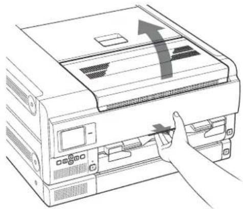
2 Wipe the thermal head with the cleaning sheet.

Caution
Do not touch the thermal head just after printing. Touching the thermal head may cause a burn since the thermal head may be hot just after printing.
Note
Before wiping the thermal head, touch the metallic part of the unit to remove static electricity from your body.

Wipe the surface of the thermal head gently with the cleaning sheet.
Notes
- Be careful not to touch the surface of the thermal head with your hand.
- Since the thermal head is still very hot just after printing is finished, be careful not touch the thermal head. Touching the hot thermal head may cause a burn.
3 Close the front cover.
Note
When you close the cover, be careful not to get your fingers or hands caught with the front cover.
Cleaning the filters
Ventilation holes are provided on the unit to prevent it from overheating.
Three filters are provided on the front cover for covering the ventilation holes.
To clean the filters, proceed as follows.
1 Pull the front cover lock lever to open the front cover.

2 Lift one of the filters upward a little and pull it toward you to remove it. Do the same with the others.

3 Clean the filters using a vacuum cleaner or the like.
Notes
- Be careful that the filter does not get caught in the vacuum cleaner.
- Do not rub the net of the filter roughly.
4
Reset the filters and close the cover.

Note
When you close the cover, be careful not to get your fingers or hands caught with the front cover.
After you have finished all cleaning tasks
Turn the unit on by pressing the ⏻ON/STANDBY switch on the front panel.
The "Film Station" logo is shown on the LCD panel. Then the following screen appears.
![graph TD A["Initializing"] --> B["TRAY: 1"] A --> C["TRAY: 2"]](/content/2026/08/1617581/images/58b7a376a917d9a2fa6de8dbddfbaf52f6ed4472f8ede0e6cc094581463d7247.jpg)
When the following message appears on the LCD after several minutes, you can start printing again.

Specifications
Power requirements
AC 100 V-240 V, 50/60 Hz
Input current 4.4 A-2.4 A
Operating temperature
10 °C to 30 °C (50 °F to 86 °F)
Operating humidity
20% to 80% (no condensation allowed)
Operating pressure
700 hPa to 1,060 hPa
Storage and transport temperature
-20°C to +60°C (-4°F to +140°F)
Storage and transport humidity
20% to 80% (no condensation allowed)
Storage and transport pressure
700 hPa to 1,060 hPa
Dimensions Approx. 600 × 316 × 686 mm (w/h/d)
(23 5/8 × 12 1/2 × 27 1/8 inches) (Without including projecting parts)
Mass Approx. 66 kg (145 lb 8.1 oz)
Printing system Thermal printing
Resolution 23.78 dot/mm (604 dpi)
Gradations 16,384 levels processing
Maximum print size
346.7 × 415.3 mm (when using the UPT-517BL)
Picture elements
8,256 × 9,888 dots (w/h) (when using the UPT-517BL)
Throughput Approx. 100 sheets/hour (excluding the time for cooling the head) (when using the UPT-517BL)
Digital interface
Network port × 1
(RJ-45 Modular jack), Conforming to 1000BASE-T/100BASE-TX standard
Input connector AC IN (for power)
Accessories supplied
Output tray (1)
Cleaning Kit (1)
Output tray stopper (1)
Film tray size adapter kit (1)
Instructions for Use (1)
Accessories supplied separately
Blue Thermal Film UPT-517BL
Blue Thermal Film UPT-514BL
Blue Thermal Film UPT-512BL
Blue Thermal Film UPT-510BL
Cleaning kit UPA-500
Medical Specifications
Protection against electric shock: Class I
Protection against harmful ingress of water: Ordinary
Degree of safety in the presence of a flammable anesthetic mixture with air or with oxygen or nitrous oxide:
Not suitable for use in the presence of a flammable anesthetic mixture with air or with oxygen or nitrous oxide
Mode of operation: Continuous
Design and specifications are subject to change without notice.
Notes
- Always verify that the unit is operating properly before use. SONY WILL NOT BE LIABLE FOR DAMAGES OF ANY KIND INCLUDING, BUT NOT LIMITED TO, COMPENSATION OR REIMBURSEMENT ON ACCOUNT OF FAILURE TO PRINT CONTENT OF ANY TYPE OR LOSS OF DATA DUE TO FAILURE OF THIS UNIT OR ITS PRINTING MEDIA, ASSOCIATED SOFTWARE, EXTERNAL STORAGE, OR OTHER EXTERNAL DEVICE.
- SONY WILL NOT BE LIABLE FOR DAMAGES OF ANY KIND INCLUDING, BUT NOT LIMITED TO, COMPENSATION OR REIMBURSEMENT ON ACCOUNT OF THE LOSS OF PRESENT OR PROSPECTIVE PROFITS DUE TO FAILURE OF THIS UNIT, EITHER DURING THE WARRANTY PERIOD OR AFTER EXPIRATION OF THE WARRANTY, OR FOR ANY OTHER REASON WHATSOEVER.
- SONY WILL NOT BE LIABLE FOR CLAIMS OF ANY KIND MADE BY USERS OF THIS UNIT OR MADE BY THIRD PARTIES.
- SONY WILL NOT BE LIABLE FOR THE TERMINATION OR DISCONTINUATION OF ANY SERVICES RELATED TO THIS UNIT THAT MAY RESULT DUE TO CIRCUMSTANCES OF ANY KIND.
If the unit is suddenly taken from a cold to a warm location, or if ambient temperature suddenly rises, moisture may form on the outer surface of the unit and/or inside of the unit. This is known as condensation. If condensation occurs, turn off the unit and wait until the condensation clears before operating the unit. Operating the unit while condensation is present may damage the unit.
LCD image display
Due the physical characteristics of LCD panels, there may be a decrease in brightness or change in color temperature over a long period of use. These problems are not a malfunction.
In addition, these occurrences will not affect recorded data.
The fan is a consumable part that will need periodic replacement.
When operating at room temperature, a normal replacement cycle will be about 5 years.
However, this replacement cycle represents only a general guideline and does not imply that the life expectancy of this part is guaranteed. For details on parts replacement, contact your dealer.
The life expectancy of the electrolytic capacitor is about 5 years under normal operating temperatures and normal usage (8 hours per day; 25 days per month). If usage exceeds the above normal usage frequency, the life expectancy may be reduced correspondingly.
Notes on security
- SONY WILL NOT BE LIABLE FOR DAMAGES OF ANY KIND RESULTING FROM A FAILURE TO IMPLEMENT PROPER SECURITY MEASURES ON TRANSMISSION DEVICES, UNAVOIDABLE DATA LEAKS RESULTING FROM TRANSMISSION SPECIFICATIONS, OR SECURITY PROBLEMS OF ANY KIND.
- Depending on the operating environment, unauthorized third parties on the network may be able to access the unit. When connecting the unit to the network, be sure to confirm that the network is protected securely.
SMPTE Test Pattern - RP133- Copyright 1983
SOP and Meta SOP Classes
| SOP Class Name SOP Class UID | |
| Verification SOP Class 1.2.840.10008.1.1 | |
| Basic Grayscale Print Management Meta SOP Class | 1.2.840.10008.5.1.1.9 |
| Basic Film Session SOP Class 1.2.840.10008.5.1.1.1 | |
| Basic Film Box SOP Class 1.2.840.10008.5.1.1.2 | |
| Basic Grayscale Image Box SOP Class | 1.2.840.10008.5.1.1.4 |
| Print SOP Class 1.2.840.10008.5.1.1.16 | |
| Basic Annotation Box SOP Class 1.2.840.10008.5.1.1.15 | |
| Presentation LUT SOP Class 1.2.840.10008.5.1.1.23 | |
UPA-500 Cleaning Kit
The UPA-500 Cleaning Kit is designed for use with the UP-DF500/DF550/DF750/DF760.
The UPA-500 Cleaning Kit includes the following three cleaning supplies.
- Cleaning sheets
Used for cleaning the thermal head.
- Lapping film
Used during periodic maintenance performed by a Sony service representative. Keep this stored safely until the periodic maintenance.
- Cleaning roller
For details on replacing the cleaning roller and cleaning the thermal head, see “Maintenance” on page 38.
About the Blue Thermal Film (UPT-517BL/514BL/512BL/510BL)
Precautions
- Store unopened film in a cool dark place.
- Open film only when ready to use.
- Please refer to the imager's instruction manual about how to load the film.
- Prompty load the film into the tray and place into the imager.
- This film is specifically designed for Sony imagers. Do not use with imagers from other manufactures.

Do not Reuse
Doing so may result in malfunction and negatively affect printing results.

This symbol indicates the batch code.

This symbol indicates the use-by date.
Messages
There are two kinds of messages: error messages and warning messages. This section lists these messages together with their possible causes and remedies. Note the messages and act accordingly.
Besides error and warning messages, other messages stating the operating status of the unit are also displayed.
Those messages are not described here.
Error Messages
If a problem occurs, the ALARM indicator lights and an error message as well as an illustration indicating required steps appear on the LCD panel. Perform the appropriate action, as indicated below.
![Film Station [1]Set Film TRAY: 1 Set Film TRAY: 2 Set Film](/content/2026/08/1617581/images/1933c443d34f1ade72d65815dc61ef782962dcc4a095d4da0bd2582e3aaf19e2.jpg)
| Message Cause/Countermeasures | |
| Close Cover The front, rear, or top cover is open.→Close the cover. | |
| Memcon/0 Trouble Memcon/1 Trouble | An internal error has occurred in the printer.→Press the ⏻ ON/STANDBY switch to turn the power off, and then turn the power on again by pressing the ⏻ ON/STANDBY switch once more. Normally this will restore correct operation. If the above steps do not provide a solution and the message appears again, turn power to the unit off and contact your Sony dealer. |
| Mecha Trouble (Mechanical problem) | A mechanical problem has occurred in the printer.→Press the ⏻ ON/STANDBY switch to turn the power off, and then turn the power on again by pressing the ⏻ ON/STANDBY switch once more. Normally this will restore correct operation. If the above steps do not provide a solution and the message appears again, turn power to the unit off and contact your Sony dealer. |

| Message Cause/Countermeasures | |
| Remove FilmXXXXXX1) | Film has jammed at the location indicated by XXXXXX. Refer to the illustration shown on the LCD panel and remove the jammed film. |
| ErrorPlease Power OFFPower ON Again | Internal system of printer could not be started. |
[*] Set Tray The required film tray is not installed. | |
[*] Check Tray2) Film is not loaded correctly in film tray. | |
Set Output Tray Output tray is not installed correctly. | |
[*] Set Film2) Film sheets in the specified tray have  | |
[*] Tag Mismatch2) The IC tag setting of the film sheets in the tray does not match the IC tag setting at the printer.  | |
[*] Tag Invalid T2) There is a problem with the IC tag. | |
[*] Tag Invalid I2)  | |
Remove Prints Printouts have accumulated on the output tray. | |
Dicom Trouble There is a problem with the DICOM section. | |
| Please Power OFFPlace the Unit HorizontallyAnd Power ON Again | This unit cannot be placed vertically. |
[*] stands for the tray number (1 or 2).
1) "XXXXXX" indicates the location where the film jam has occurred. For details, see "If the Film Sheets Jams" on page 45.
2) If the error has occurred on one tray only, the ALARM indicator will not light, and the READY indication is always shown. In this case, instead of an error message, the tray status indication on the LCD panel changes as follows.
| Corresponding error message | Tray status indication |
| [*] Check Tray Chk Tray | |
| [*] Set Film | Set Film |
| [*] Tag Mismatch | Tag Err M |
| [*] Tag Invalid T | Tag Err T |
| [*] Tag Invalid I | Tag Err I |
| Remove Prints | Rmv Prt |
Other messages
Besides messages indicating an error, various status messages may also be shown on the LCD panel, as listed below.
In these cases, the ALARM indicator does not light.

| Message | Cause/Countermeasures |
| Please Wait | The thermal head temperature has exceeded normal levels.→Wait until the message disappears. |
| Head Cooling | During continuous printing, operation will resume when the head has cooled down and the message disappears. |
| Please Wait | The thermal head is currently being warmed up.→Wait until the message disappears. |
| Head Heating | Printing will start when the head has been warmed up and the message disappears. |
| Please Wait | The printer is performing an internal processing operation such as when the film tray is opened or closed. The message is also shown during power-down.→Wait until the indication disappears. |
Message Cause/Countermeasures
| Initializing (Flashes) | Indicates that the printer is carrying out an initialization routine, such as when the cover was closed or a network setting such as the IP address was changed.→Wait until the indication disappears. |
| - | |
| Processing Reserved | Image data are being processed. |
| - | |
| - | In the current condition, a problem could occur due to the combination of the size of film inserted in the film tray and the type of output tray that is installed. (page 14) |
| Output Tray Mismatch | Contact your Sony dealer to have the output tray size changed. |
(The part above the dotted line refers to the status indication, and the part below the dotted line refers to the job information field.)
Troubleshooting
If Damage is Suspected
If a problem appears, check the following trouble shooting guide first and perform whatever action is recommended to solve the problem. If the problem persists, turn off the printer and consult your Sony dealer.
Symptom Possible causes and remedies
| Nothing appears on the LCD. | The ON/STANDBY switch on the front panel of the unit is not pressed.→Press the ON/STANDBY switch to turn the unit on. (Page 16)The connections may not be correct.→Make the connections correctly. (Page 15) |
| The unit has not turned on even though the ON/STANDBY switch on the front panel is pressed. | The I/O main power switch on the rear panel is not set to on (I).→Set the I/O main power switch on the rear panel to on (I). (Page 15) |
| The ON/STANDBY switch does not work. | Set the I/O main power switch to off (O) once, then set the I/O main power switch to on (I) again. If the ON/STANDBY switch still does not work, turn the power off and contact you Sony dealer. |
| The unit does not print. | An error message appears on the LCD.→Take the measures recommended in “Messages.” (page 43) |
If the Film Sheets Jams
If a film jam occurs before starting to print or during printing, the error message “Remove Film XXXXXX” appears, and printing stops. The “XXXXXX” shows where the jam has occurred. Check this location and remove the jammed film. When the film has been removed, the error message disappears, and image data that have not yet been output will be printed. Locations indicated by “XXXXXX” are as follows.

| “XXXXXX” string (jam location) | Countermeasure |
| Tray 1 (Film tray 1)Tray 2 (Film tray 2) | For information on how to remove film jammed in the film tray, see page 46. |
| Rear 1 or 2 (Rear cover 1 or 2)Top (Top cover)Front (Front cover)Top & Inner 1 (Top cover and inner cover 1)Top & Inner 2 (Top cover and inner cover 2) | For information on how to remove film jammed inside the printer, see page 47. |
| Output tray For information on how to remove film jammed in the output tray, see page 48. | |
| Some places (Multiple locations) | For information on how to remove film jammed in multiple locations, see page 49. |
Notes
- When you put your hands inside of the unit, be careful not to hurt yourself by touching hot or sharp parts.
- If you turn off the power, image data that has not been printed yet is cleared.
To remove film jammed in the film tray
1 Remove the corresponding film tray.
When the unit is not turned on, you can pull the film tray out without pushing the EJECT TRAY button.
Notes
- If any printouts have been ejected onto the film tray, remove them first before removing the film tray.
- When you pull out the film tray, hold both sides of the film tray and the tray cover with both hands.
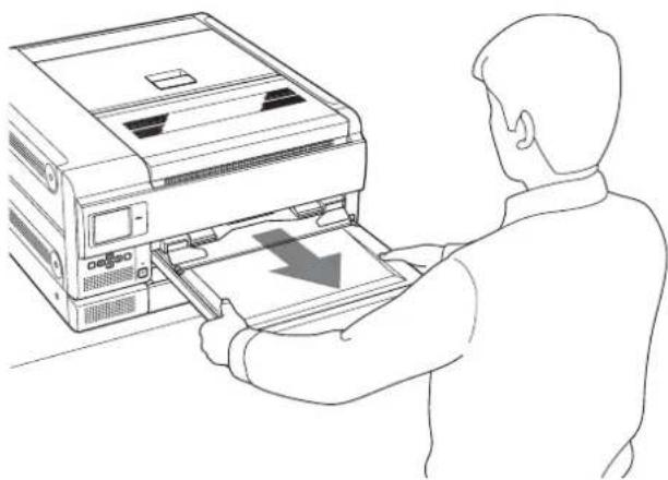
2 Remove jammed film according to the status displayed.
When a film sheet pops out from the shutter of the feeding position of the film tray:
Remove the jammed film sheet slowly while holding the film with both hands.
Do not reuse the removed film. Discard it.
When a film sheet is jammed between the feeding position and the shutter of the film tray:
Put it back in the film tray.

When a film sheet is jammed inside the unit:
Remove the jammed film sheet slowly while holding the film sheet with both hands.
Do not reuse the removed film. Discard it.
3 Re-insert the film tray as it was.
If you can see the film sheets in the film tray
If you slant the film tray, the film sheets may move to the outlet of the film tray. This may cause film jamming. In such a case, put the film sheets back inside the film tray by pushing them with your fingers, as shown.

To remove film jammed inside the printer
1 Open the cover indicated in the message and remove the jammed film sheet slowly while holding the film with both hands.
When rear cover 1 is opened

When rear cover 2 is opened

Note
When you have to open rear cover 1 and rear cover 2 at the same time, open rear cover 2 first, and then rear cover 1. When you close the rear covers, close rear cover 1 first, and then rear cover 2.
When the top cover is opened
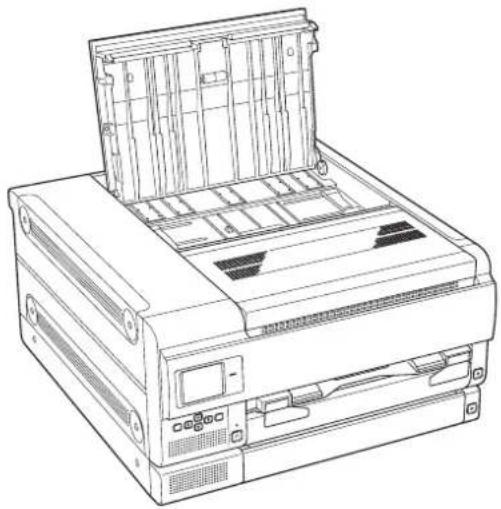
When the front cover is opened
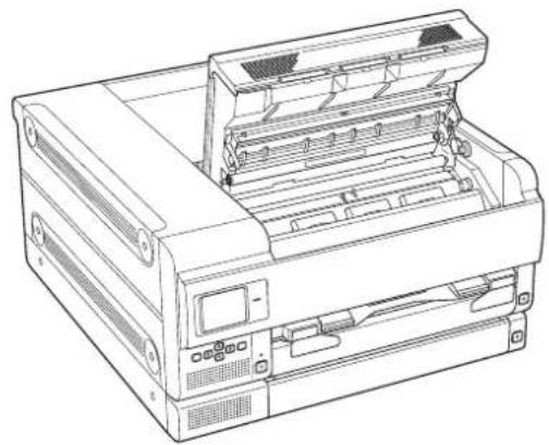
When the top cover and front cover are opened


When the top cover and inner cover 1 are opened

When the top cover, inner cover 1, and inner cover 2 are opened

2 Close the opened cover(s) firmly.
Note
When you close the covers, be careful not to get your fingers or hands caught with the covers.
The following message appears on the LCD.
![graph TD A["Initializing"] --> B["TRAY: 1"] A --> C["TRAY: 2"]](/content/2026/08/1617581/images/f264e685652c1b34cf3b12ec38311211fdc992bba1d8cc4814246f16af666414.jpg)
Wait until the message disappears.
When the unit enters standby status, the following message appears.
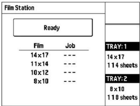
To remove film jammed in the output tray
1 Remove the output tray completely.

2 Remove the jammed film near the inside of the unit.

3 Re-insert the output tray as it was.
Note
Be sure to insert the output tray completely. For detailed information on how to insert the output tray completely, see page 14.
To remove film jammed in multiple locations
Open all of the covers, rear, front, top, and inner covers and check the location of the jammed film.
The jam may also be located near the film tray. Remove the film tray to check.
License
“zlib”, “The FreeType Project LICENSE” and “OpenSSL” software are used in this unit. We use these software based on license agreements with their owners of copyright. Based on requests by the owners of copyright of these software applications, we have an obligation to inform you of the following.
zlib
(C) 1995-1998 Jean-loup Gailly and Mark Adler
The FreeType Project LICENSE
Copyright 1996-2002 by David Turner, Robert Wilhelm, and Werner Lemberg
Source code provided by the FreeType Project is used for TrueType font rasterizing.
OpenSSL
Copyright (c) 1998-2011 The OpenSSL Project. All rights reserved.
Redistribution and use in source and binary forms, with or without modification, are permitted provided that the following conditions are met:
- Redistributions of source code must retain the above copyright notice, this list of conditions and the following disclaimer.
- Redistributions in binary form must reproduce the above copyright notice, this list of conditions and the following disclaimer in the documentation and/or other materials provided with the distribution.
- All advertising materials mentioning features or use of this software must display the following acknowledgment: "This product includes software developed by the OpenSSL Project for use in the OpenSSL Toolkit. (http://www.openssl.org/)
- The names "OpenSSL Toolkit" and "OpenSSL Project" must not be used to endorse or promote products derived from this software without prior written permission. For written permission, please contact openssl-core@openssl.org.
- Products derived from this software may not be called "OpenSSL" nor may "OpenSSL" appear in their names without prior written permission of the OpenSSL Project.
- Redistributions of any form whatsoever must retain the following acknowledgment:
"This product includes software developed by the OpenSSL Project for use in the OpenSSL Toolkit (http://www.openssl.org/)
THIS SOFTWARE IS PROVIDED BY THE OpenSSL PROJECT "AS IS" AND ANY EXPRESSED OR IMPLIED WARRANTIES, INCLUDING, BUT NOT LIMITED TO, THE IMPLIED WARRANTIES OF

MERCHANTABILITY AND FITNESS FOR A PARTICULAR PURPOSE ARE DISCLAIMED. IN NO EVENT SHALL THE OpenSSL PROJECT OR ITS CONTRIBUTORS BE LIABLE FOR ANY DIRECT, INDIRECT, INCIDENTAL, SPECIAL, EXEMPLARY, OR CONSEQUENTIAL DAMAGES (INCLUDING, BUT NOT LIMITED TO, PROCUREMENT OF SUBSTITUTE GOODS OR SERVICES; LOSS OF USE, DATA, OR PROFITS; OR BUSINESS INTERRUPTION) HOWEVER CAUSED AND ON ANY THEORY OF LIABILITY, WHETHER IN CONTRACT, STRICT LIABILITY, OR TORT (INCLUDING NEGLIGENCE OR OTHERWISE) ARISING IN ANY WAY OUT OF THE USE OF THIS SOFTWARE, EVEN IF ADVISED OF THE POSSIBILITY OF SUCH DAMAGE.
This product includes cryptographic software written by Eric Young (eay@cryptsoft.com). This product includes software written by Tim Hudson (tjh@cryptsoft.com).
Original SSLeay License
Copyright (C) 1995-1998 Eric Young
(eay@cryptsoft.com)
All rights reserved.
This package is an SSL implementation written by Eric Young (eay@cryptsoft.com).
The implementation was written so as to conform with Netscapes SSL.
This library is free for commercial and non-commercial use as long as the following conditions are aheared to. The following conditions apply to all code found in this distribution, be it the RC4, RSA, lhash, DES, etc., code; not just the SSL code. The SSL documentation included with this distribution is covered by the same copyright terms except that the holder is Tim Hudson (tjh@cryptsoft.com).
Copyright remains Eric Young's, and as such any Copyright notices in the code are not to be removed.
If this package is used in a product, Eric Young should be given attribution as the author of the parts of the library used.
This can be in the form of a textual message at program startup or in documentation (online or textual) provided with the package.
Redistribution and use in source and binary forms, with or without modification, are permitted provided that the following conditions are met:
-
Redistributions of source code must retain the copyright notice, this list of conditions and the following disclaimer.
-
Redistributions in binary form must reproduce the above copyright notice, this list of conditions and the following disclaimer in the documentation and/or other materials provided with the distribution.
-
All advertising materials mentioning features or use of this software must display the following acknowledgement:
"This product includes cryptographic software written by Eric Young (eay@cryptsoft.com)" The word 'cryptographic' can be left out if the rouines from the library being used are not cryptographic related :-).
- If you include any Windows specific code (or a derivative thereof) from the apps directory (application code) you must include an acknowledgement:
"This product includes software written by Tim Hudson (tjh@cryptsoft.com)"
THIS SOFTWARE IS PROVIDED BY ERIC YOUNG "AS IS" AND ANY EXPRESS OR IMPLIED WARRANTIES, INCLUDING, BUT NOT LIMITED TO, THE IMPLIED WARRANTIES OF MERCHANTABILITY AND FITNESS FOR A PARTICULAR PURPOSE ARE DISCLAIMED. IN NO EVENT SHALL THE AUTHOR OR CONTRIBUTORS BE LIABLE FOR ANY DIRECT, INDIRECT, INCIDENTAL, SPECIAL, EXEMPLARY, OR CONSEQUENTIAL DAMAGES (INCLUDING, BUT NOT LIMITED TO, PROCUREMENT OF SUBSTITUTE GOODS OR SERVICES; LOSS OF USE, DATA, OR PROFITS; OR BUSINESS INTERRUPTION) HOWEVER CAUSED AND ON ANY THEORY OF LIABILITY, WHETHER IN CONTRACT, STRICT LIABILITY, OR TORT (INCLUDING NEGLIGENCE OR OTHERWISE) ARISING IN ANY WAY OUT OF THE USE OF THIS SOFTWARE, EVEN IF ADVISED OF THE POSSIBILITY OF SUCH DAMAGE.
The licence and distribution terms for any publicly available version or derivative of this code cannot be changed.
i.e. this code cannot simply be copied and put under another distribution licence [including the GNU Public Licence.]
Index
A
Adjusting the print quality sharpness 29
C
Calibration auto calibration 32 calibrating the unit for each film type 31
Cleaning cabinet 38 filters 40 thermal head 39
Cleaning roller 39
Connections 15
Cover front cover 47 inner cover 1 48 inner cover 2 48 rear cover 1 47 rear cover 2 47 top cover 47
F
Film confirming the remaining amount of film sheets 18 loading 19 note on storing 23 recommended film 18 removing the jammed film 45 when film sheets run out during printing 25
Film tray 1 18
Film tray 2 18
G
Gamma curve 33
|
IC tag 21
L
Location and function of parts and controls front panel 10 rear panel 10
M
Maintenance cleaning the filters 40 cleaning the thermal head 39 replacing the cleaning roller 39
Menu
Calibration 31 Configuration 27 Default Gamma 33 Information 28 System Settings 35 Test Print 36
Menu operation calibrating the printing density 31 confirming information 28 LCD panel settings 34 making network 34 selecting a gamma curve 33 test print 36
Messages error messages 43 other messages 44
0
Output tray 14
P
Placing the Unit 15 Power turning on the main power 15 turning the unit on 16 Precautions condensation 38 installation 38 safety 38 transporting the unit 38
Printing before printing 23 if the unit does not print 25
Printouts adjusting the sharpness of printouts 28 note on storing 25 pattern printout 29
R
Removing jammed film sheets 45
S
SOP and Meta SOP classes 43 Specifications 41 Supplied accessories assembly 14 checking 13
cleaning kit 39 System configuration example 9 feature 9
T
Troubleshooting if damage is suspected 45 if the film jams 45
Setup Manual
This Setup Manual provides information for system administrators about the topics listed below, including the setup procedure for connecting the UP-DF760 (subsequently called “the unit”) to a network. The Setup Manual consists of the following parts.
- Setup
Explains how to specify the IP address and perform other setup steps that are necessary for connecting the unit to a network.
Table of Contents
Setup
About the IP Address ....53
Checking the IP Address ....53
Setting the IP Address ....53
Completion Check 57
Network Setup Screen Transition Diagram .....58
Setup
About the IP Address
When you use the unit for the first time immediately after you purchase the unit, it is necessary to make settings for the DICOM section integrated in the unit, such as specifying the IP address and so on. Before starting the setup procedure, confirm the following with the network administrator.
• The IP address that the unit will use on the network
- Subnet mask of the network
- Gateway address, if a gateway is included in the network
Checking the IP Address
To confirm the IP address, perform the following steps.
1 Turn on the unit.
2 Press the MENU button. The menu screen appears.
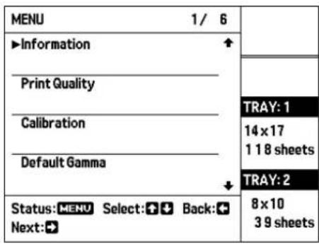
3 Use the ⇔ and ⇔ buttons to move the cursor to "Information" and press the ⇔ button. The current IP address setting is shown.

Setting the IP Address
To assign an IP address to be used by the unit, perform the following steps.
Note
If network settings are changed by mistake to unsuitable values, the unit will no longer be accessible via the network. Network settings should only be changed by the system administrator.
1 Press the MENU button. The menu screen appears.

2 Use the and buttons to move the cursor to "System Settings" and press the ⇔ button. The following screen appears.

3 Press the ⇒ button. The network setup screen appears.

Up to five different network settings can be saved in the unit as Presets.
You can call up a Preset and apply network settings by one of the following two methods. For details, refer to the indicated page.
- Editing a Preset (Preset 1 - 5) and applying the new settings (page 54)
- Calling up a Preset (Preset 1 - 5) and applying its settings (page 56)
Note
If no button of the unit is operated during network setup for a period of about 30 minutes, the unit reverts to the standard screen. Any settings that were made up to that point will be lost.
Editing a preset and using the result as network settings
1 Use the ⇔ and ⇔ buttons to move the cursor to "Edit" and press the ⇔ button.

The Edit Preset screen appears.

2 Press the ⇒ button.
A screen for selecting the Preset (Preset 1 - 5) or "Temporary" appears.
Settings made after selecting "Temporary" will not be stored as a Preset but used only as network settings for the unit.
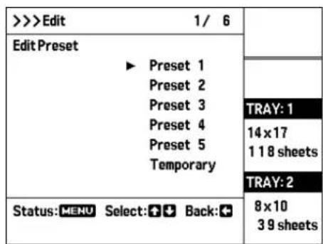
3 Use the ⇔ and ⇔ buttons to move the cursor to the number of the Preset to edit and press the ⇔ button. (In this example, "Preset 1" is selected.) The Edit Preset screen appears again.

4 Use the ⇔ and ⇔ buttons to move the cursor to "PresetName" and press the ⇔ button. The following screen appears.
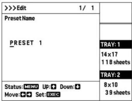
5 Change the Preset name. Use the ⇔ and ⇔ buttons to change the character above the cursor. Use the ⇔ and ⇔ buttons to move the cursor.
6 Press the EXEC button. The IP Address Setup screen appears.
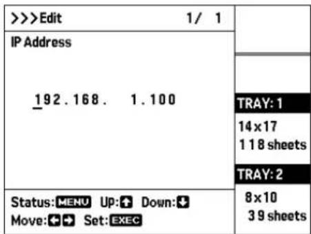
7 Change the IP address setting. Use the ⇔ and ⇔ buttons to change the value above the cursor. Use the ⇔ and ⇔ buttons to move the cursor.
8 Press the EXEC button. The Subnet Mask setting screen appears.
9 Use the procedure of steps 7 and 8 to make the Subnet Mask and Default Gateway settings. After the Default Gateway setting has been confirmed (by pressing the EXEC button), the screen for setting the AE Title appears.

10 Set the AE title. Use the ⇧ and ⇧ buttons to change the character above the cursor. Use the ⇧ and ⇧ buttons to move the cursor.
Note
You can specify any character string (such as "SONY") as AE title, but once the string has been set, a print request calling an AE title that does not match the string will not be accepted. To allow a request with any called AE title to be accepted, make the AE title blank.
11 Press the EXEC button. The screen for setting the port number appears.

12 Change the port number. Use the ⇧ and ⇧ buttons to change the value above the cursor. Use the ⇧ and ⇧ buttons to move the cursor.

13 Press the EXEC button.
The Save Settings screen appears.

14 Move the cursor to "YES" and press the EXEC button.
The settings made up to this point will be applied as the unit's network settings. If "Temporary" was selected in step 2, the Preset contents remain unchanged and the settings made up to this point will be applied as the unit's network settings.
The network settings will be activated after the "Initializing" indication on the LCD has disappeared. Activation of the network settings may take a few minutes.
Calling up a preset and using the result as network settings
1 Use the ⇔ and ⇔ buttons to move the cursor to the number of the Preset to use and press the ⇔ button. (In this example, "Preset 2" is selected.)
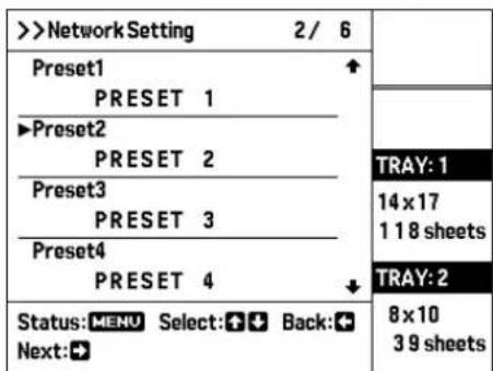
The current settings of "Preset 2" are shown.

2 Use the ⇔ and ⇔ buttons to move the cursor to "Save Settings" and press the ⇔ button.

The Save Settings screen appears.

3 Move the cursor to "YES" and press the EXEC button.
The currently shown settings (saved as Preset 2) will be applied as the unit's network settings. The network settings will be activated after the "Initializing" indication on the LCD has disappeared. Activation of the network settings may take a few minutes.
Completion Check
After the setup procedure is completed, perform the following steps to verify that the settings have been correctly implemented.
1 Connect the unit to the network.
2 Turn on the unit.
3 Mount a tray with blue thermal film loaded.
4 Send image data from the modality.
If the unit has been set up correctly, printing starts.
If printing does not start, the image data have not reached the printer. This means that the network settings are incorrect.
Check the IP address and other network settings of the unit, and also verify that the correct settings are being used at the modality side.
Network Setup Screen Transition Diagram
This diagram shows the overall flow of the network setup procedure. Use it when wishing to return to earlier screens etc.

![graph TD A["Network Setting"] --> B["Preset 1~5"] B --> C["Edit"] C --> D["Edit Preset"] D --> E["Preset Name"] E --> F["IP Adress"] F --> G["Subnet Mask"] G --> H["Default Gateway"] H --> I["AE Title"] I --> J["Port"] J --> K["Save Setting"] K --> L["Exec"] C --> M["Edit Preset"] M --> N["Preset Na…](/content/2026/08/1617581/images/75d753c0f48327316e178d852e18a7eb710a018d888ec3f9e2ace459a4d64da3.jpg)

- INSTRUCTIONS FOR USE PAGE 8 SETUP MANUAL PAGE
- WARNING
- SYMBOLS ON THE PRODUCTS
- CONSULT THE INSTRUCTIONS FOR USE
- STORAGE AND TRANSPORT TEMPERATURE
- STORAGE AND TRANSPORT HUMIDITY
- STORAGE AND TRANSPORT PRESSURE
- IMPORTANT SAFEGUARDS/NOTICES FOR USE IN THE MEDICAL ENVIRONMENTS
- IMPORTANT EMC NOTICES FOR USE IN THE MEDICAL ENVIRONMENTS
- CAUTION
- WARNING ON POWER CONNECTION
- INSTRUCTIONS FOR USE
- TABLE OF CONTENTS
- INTRODUCTION
- PREPARATION
- OPERATION
- ADJUSTMENT
- MISCELLANEOUS
- SYSTEM OVERVIEW
- SYSTEM CONFIGURATION EXAMPLE
- LOCATION AND FUNCTION OF PARTS AND CONTROLS
- LIQUID CRYSTAL DISPLAY (LCD) (11)
- ALARM INDICATOR (43)
- FRONT COVER (47)
- TOP COVER (47)
- VENTILATION HOLES
- ELECT TRAY BUTTON
- EJECT TRAY BUTTON
- FILM OUTPUT SLOT
- OUTPUT TRAY (14)
- FRONT COVER LOCK LEVER
- NOTE
- LCD PANEL INDICATION
- STANDARD SCREEN (WHEN ERROR HAS OCCURRED)
- ERROR COUNTERMEASURE ILLUSTRATION
- ERROR MESSAGE
- ③ FILM TRAY 1 INFORMATION
- FILM TRAY 2 INFORMATION
- MENU SCREEN (MENU ITEM LIST)
- MENU ITEM NUMBER
- MENU ITEM
- ③OPERATION GUIDANCE
- MENU SCREEN (SETTINGS SCREEN)
- MENU ITEM NAME
- SETTING VALUE
- SUPPLIED ACCESSORIES
- NOTES
- REMOVING THE PACKING MATERIALS
- ASSEMBLY
- OUTPUT TRAY SIZE
- LARGE SIZE
- SMALL SIZE
- PLACING THE UNIT
- CONNECTIONS
- NOTES ON THE LAN CABLE
- TURNING THE UNIT ON OR OFF
- TURNING THE MAIN POWER OF THE UNIT ON
- TURNING THE UNIT ON
- WHEN YOU USE THE UNIT FOR THE FIRST TIME
- WHEN YOU ALREADY USE THE UNIT
- TURNING THE UNIT OFF
- WHEN YOU DO NOT INTEND TO USE THE PRINTER FOR A LONG TIME
- LOADING FILM SHEETS
- RECOMMENDED FILM SHEETS
- BLUE THERMAL FILM UPT-517BL
- BLUE THERMAL FILM UPT-514BL
- BLUE THERMAL FILM UPT-512BL
- BLUE THERMAL FILM UPT-510BL
- ABOUT THE FILM TRAY
- FILM TRAY
- CONFIRMING THE REMAINING AMOUNT OF FILM
- TO CALIBRATE THE PRINTING DENSITY
- IF THE COVER OF THE FILM TRAY COMES OFF
- NOTES ON STORING FILM SHEETS
- PRINTING
- BEFORE PRINTING
- EXAMPLE: IMAGE SENT TO FILM TRAY 1 (SIZE 14 × 17 (ABOUT 353 × 430 MM) FILM)
- IF THE UNIT DOES NOT PRINT
- WHEN THE FILM SHEETS RUN OUT DURING PRINTING
- NOTES ON STORING YOUR PRINTOUTS
- ADJUSTMENT AND SETTING USING A MENU
- MENU CONFIGURATION
- MENU OPERATION
- CONFIRMING INFORMATION
- ADJUSTING THE PRINT QUALITY
- CHART OF THE LOW TONE RANGE
- TO RESET TO THE DEFAULT SETTING OF THE LOW TONE RANGE
- PRESS THE EXEC BUTTON
- ADJUST THE HIGH TONE
- CHART OF THE HIGH TONE RANGE
- TO RESET TO THE DEFAULT SETTING OF THE HIGH TONE RANGE
- CALIBRATING THE PRINTING DENSITY
- TO PERFORM CALIBRATION OF EACH BLUE THERMAL FILM
- TO PERFORM CALIBRATION OF ANOTHER BLUE THERMAL FILM
- TO MAKE AN AUTOMATIC CALIBRATION
- TO RESET TO THE DEFAULT STATUS
- TO RESET ANOTHER TYPE OF BLUE THERMAL FILM TO THE DEFAULT STATUS
- SELECTING A GAMMA CURVE
- MAKING NETWORK AND LCD PANEL SETTINGS
- NETWORK SETTING
- LCD BACKLIGHT
- LCD BRIGHTNESS
- LCD CONTRAST
- LANGUAGE
- TEST PRINT
- PRESS THE ⇒ BUTTON
- PRESS THE ⇧ OR ⇧ BUTTON TO MOVE THE CURSOR TO THE FILM SIZE THAT YOU WANT TO USE
- PRESS THE EXEC BUTTON. THE TEST IMAGE PATTERN IS PRINTED. WHEN PRINTING IS COMPLETED, THE FOLLOWING SCREEN APPEARS
- OTHER SETTINGS
- PRECAUTIONS
- SAFETY
- INSTALLATION
- CONDENSATION
- TRANSPORTING THE UNIT
- CLEANING THE CABINET
- TO CLEAN THE CABINET
- MAINTENANCE
- REPLACING THE CLEANING ROLLER
- CLEANING THE THERMAL HEAD
- CLEANING THE FILTERS
- AFTER YOU HAVE FINISHED ALL CLEANING TASKS
- SPECIFICATIONS
- MEDICAL SPECIFICATIONS
- LCD IMAGE DISPLAY
- NOTES ON SECURITY
- SOP AND META SOP CLASSES
- UPA-500 CLEANING KIT
- ABOUT THE BLUE THERMAL FILM (UPT-517BL/514BL/512BL/510BL)
- DO NOT REUSE
- MESSAGES
- ERROR MESSAGES
- OTHER MESSAGES
- TROUBLESHOOTING
- IF DAMAGE IS SUSPECTED
- IF THE FILM SHEETS JAMS
- TO REMOVE FILM JAMMED IN THE FILM TRAY
- WHEN A FILM SHEET POPS OUT FROM THE SHUTTER OF THE FEEDING POSITION OF THE FILM TRAY
- WHEN A FILM SHEET IS JAMMED BETWEEN THE FEEDING POSITION AND THE SHUTTER OF THE FILM TRAY
- WHEN A FILM SHEET IS JAMMED INSIDE THE UNIT
- IF YOU CAN SEE THE FILM SHEETS IN THE FILM TRAY
- TO REMOVE FILM JAMMED INSIDE THE PRINTER
- CLOSE THE OPENED COVER(S) FIRMLY
- TO REMOVE FILM JAMMED IN THE OUTPUT TRAY
- TO REMOVE FILM JAMMED IN MULTIPLE LOCATIONS
- LICENSE
- ZLIB
- THE FREETYPE PROJECT LICENSE
- OPENSSL
- INDEX
- A
- C
- F
- G
- L
- M
- P
- R
- S
- T
- SETUP MANUAL
- SETUP
- ABOUT THE IP ADDRESS
- CHECKING THE IP ADDRESS
- SETTING THE IP ADDRESS
- EDITING A PRESET AND USING THE RESULT AS NETWORK SETTINGS
- MOVE THE CURSOR TO "YES" AND PRESS THE EXEC BUTTON
- CALLING UP A PRESET AND USING THE RESULT AS NETWORK SETTINGS
- USE THE ⇔ AND ⇔ BUTTONS TO MOVE THE CURSOR TO THE NUMBER OF THE PRESET TO USE AND PRESS THE ⇔ BUTTON. (IN THIS EXAMPLE, "PRESET 2" IS SELECTED.)
- USE THE ⇔ AND ⇔ BUTTONS TO MOVE THE CURSOR TO "SAVE SETTINGS" AND PRESS THE ⇔ BUTTON
- COMPLETION CHECK
- NETWORK SETUP SCREEN TRANSITION DIAGRAM
Brand : SONY
Model : UP-DF760
Category : Uncategorized