
B840M GAMING PLUS WIFI6E - Motherboard MSI - Free user manual and instructions
Find the device manual for free B840M GAMING PLUS WIFI6E MSI in PDF.


| Brand | MSI |
| Model | B840M GAMING PLUS WIFI6E |
| Product Type | Motherboard |
| Form Factor | Micro-ATX (244mm x 244mm) |
| Socket | AMD AM5 |
| Chipset | AMD B840 |
| Memory Support | 4 x DDR5 DIMM, up to 256GB |
| Memory Speed | DDR5 8000+ (OC) |
| Expansion Slots | 1 x PCIe 4.0 x16, 2 x PCIe 4.0 x1 |
| Storage | 2 x M.2 PCIe 4.0 x4, 4 x SATA 6Gb/s |
| Network | 2.5Gbps LAN, Wi-Fi 6E, Bluetooth 5.3 |
| Audio | 7.1-Channel HD Audio (Realtek ALC897) |
| USB Ports | USB 3.2 Gen2, USB 3.2 Gen1, USB 2.0 |
| Power Connectors | 24-pin ATX, 8-pin EPS |
| Weight | Approximately 1.2 kg |
| Maintenance and Cleaning | Use compressed air to remove dust from heatsinks and fans; clean with a soft antistatic cloth dampened with isopropyl alcohol. Avoid water and harsh chemicals. |
| Spare Parts and Repairability | CMOS battery, M.2 screws, and I/O shield are commonly replaceable. Consult the manual for component locations. Most electrical repairs require professional service. |
| Security | TPM 2.0, Secure Boot, and firmware protection features. |
| General Information | Supports AMD Ryzen 7000/8000 series processors; optimized for gaming with MSI GAMING LAN, Frozr heatsink, and Mystic Light RGB. |
Frequently Asked Questions - B840M GAMING PLUS WIFI6E MSI
User questions about B840M GAMING PLUS WIFI6E MSI
0 question about this device. Answer the ones you know or ask your own.
Ask a new question about this device
Download the instructions for your Motherboard in PDF format for free! Find your manual B840M GAMING PLUS WIFI6E - MSI and take your electronic device back in hand. On this page are published all the documents necessary for the use of your device. B840M GAMING PLUS WIFI6E by MSI.
USER MANUAL B840M GAMING PLUS WIFI6E MSI
How to find the BIOS version? 4
BIOS Setup....5
Entering BIOS Setup 5
Function key 5
BIOS Setting Mode 6
EZ Mode....6
Game Boost....7
Creation Boost....7
Al Boost....8
AXMP/ EXPO Profile 9
M-Flash 10
Favorites 12
MSI Performance Preset.... 14
Smart Button.... 15
Profile 16
Hardware monitor.... 18
Updating BIOS with M-FLASH 67
Updating the BIOS with MSI Center 68
Updating BIOS with Flash BIOS Button.... 68
Revision History 69
UEFI BIOS
MSI UEFI BIOS is compatible with UEFI (Unified Extensible Firmware Interface) architecture. UEFI has many new functions and advantages that traditional BIOS cannot achieve, and it will completely replace BIOS in the future. The MSI UEFI BIOS uses UEFI as the default boot mode to take full advantage of the new chipset's capabilities. However, it still has a CSM (Compatibility Support Module) mode to be compatible with older devices. That allows you to replace legacy devices with UEFI compatible devices during the transition.

The term BIOS in this user guide refers to UEFI BIOS unless otherwise noted.
UEFI advantages
- Fast booting - UEFI can directly boot the operating system and save the BIOS self-test process. And also eliminates the time to switch to CSM mode during POST.
• Supports for hard drive partitions larger than 2 TB.
• Supports more than 4 primary partitions with a GUID Partition Table (GPT).
• Supports unlimited number of partitions. - Supports full capabilities of new devices - new devices may not provide backward compatibility.
- Supports secure startup - UEFI can check the validity of the operating system to ensure that no malware tampers with the startup process.
Incompatible UEFI cases
•32-bit Windows operating system - this motherboard supports only Windows 1164-bit operating system.
- Older graphics card - the system will detect your graphics card. If you use older graphics cards, it may display a warning message There is no GOP (Graphics Output protocol) support detected in this graphics card.

We recommend that you replace it with a graphics card supporting GOP/UEFI or use CPU with integrated graphics for having normal function.
How to find the BIOS version?
After entering the BIOS, find the BIOS version in the information box.

BIOS Setup
The default settings offer optimal performance for system stability in normal conditions. You should always keep the default settings to avoid possible system damage or failure booting unless you are familiar with BIOS.

- The BIOS setup screens, options, and settings in this manual are for reference only and may vary from the motherboard you purchased. Please refer to the actual BIOS version of your system for detailed screens, settings and options.
- In Advanced mode, you can find BIOS item descriptions at the bottom of the BIOS screen for information on the purpose and function of each BIOS setting. BIOS items are continuously updated for better system performance. Therefore, the description may differ slightly from the latest BIOS and should be for reference only.
Entering BIOS Setup
Press Delete key, when the Press DEL key to enter Setup Menu, F11 to enter Boot Menu message appears on the screen during the boot process.
Function key
+/-: Increase / decrease the value
Enter: Select the item
ESC: Exit
Tab: Next selection
Ctrl+F: Enter Search menu
F1: General Help list
F2: Add/ Remove a favorite item
F3: Enter Favorites menu
F4: Enter CPU core center & memory center information menu
F5: Enter Hardware Monitor menu
F6: Load optimized defaults
F7: Switch between Advanced mode and EZ mode
F8: Load Overclocking Profile
F9: Save Overclocking Profile
F10: Save Change and Reset*
F12: Take a screenshot and save it to USB flash drive (FAT/ FAT32 format only).
* Pressing F10 displays a confirmation message summarizing your changes. Select Yes or No to confirm.
BIOS Setting Mode
We provide two modes for you to configure BIOS settings: EZ mode and Advanced mode. Click on the EZ Mode/ Advanced (F7) button or press the F7 function key to switch between these two modes.
EZ Mode
In EZ mode, it provides the basic setup functions for easy configuration and displays basic system information and status.

Switch between EZ Config menu or Favorite menu.
Game Boost
Enabling the GAME BOOST, the BIOS will automatically configure the CPU for optimal overclocking. However, this feature is only available if both your motherboard and CPU support it.
Click here to enable or disable the Game Boost/ Creation Boost function.


Please don’t make any changes in Overclocking menu and don’t load defaults to keep the optimal performance and system stability after activating the Game Boost function.
Creation Boost
Enabling the Creation BOOST for performance optimization.

Please don’t make any changes in Overclocking menu and don’t load defaults to keep the optimal performance and system stability after activating the Creation Boost function.
AI Boost
Enabling AI Boost allows the BIOS to automatically configure the NPU for optimal settings, enhancing AI processing performance. However, this feature is only available if both your motherboard and CPU support it.
Click here to enable or disable the AI OC function.


Please don't make any changes in Overclocking menu and don't load defaults to keep the optimal performance and system stability after activating the AI Boost function.
AXMP/ EXPO Profile
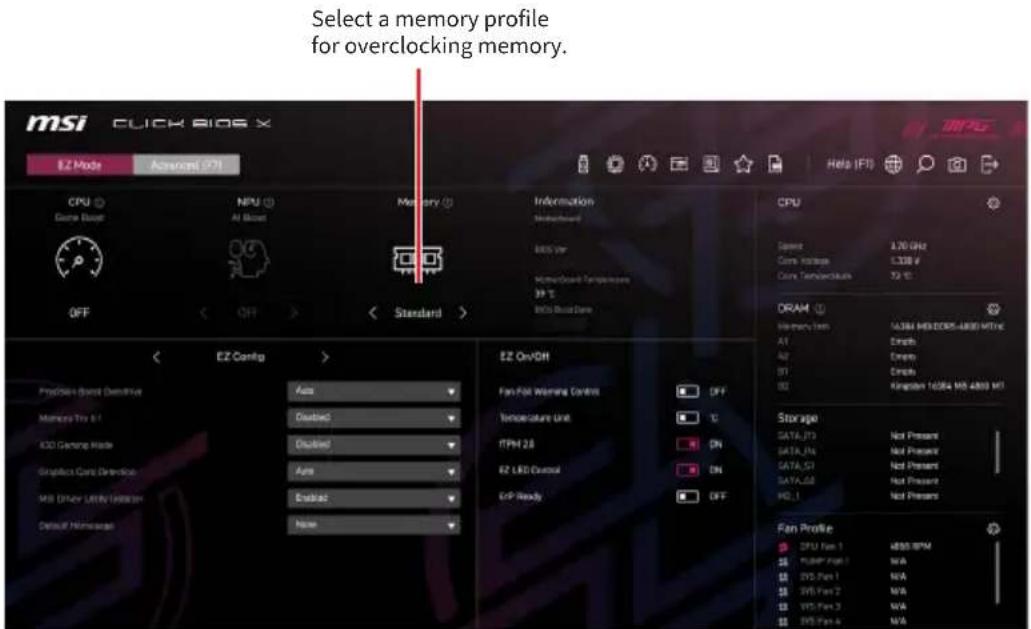
It allows you to select a memory profile for overclocking memory. However, this feature is only available if your motherboard, memory and CPU support it.
M-Flash
M-Flash makes it easy to update system BIOS with a USB flash drive.
Click this icon to enter M-Flash procedure.

Before starting the M-Flash process, make sure you have:
- A USB flash drive with a capacity of 32GB or less that is formatted to FAT32.

M-Flash only supports FAT32 format, and the USB flash drive should not exceed 32GB.
• A computer with internet access.
Please follow the steps below to update BIOS:
- Download the latest BIOS file from the MSI website that matches your motherboard model, and save it to the USB flash drive.
- If your motherboard has a Multi-BIOS switch, switch to the target BIOS ROM.
- Insert the USB flash drive into your motherboard's USB port.
- Enter flash mode by either:
- Rebooting and pressing Ctrl + F5 during POST, then clicking Yes to reboot the system.
Press
- Rebooting and pressing Del during POST to enter BIOS, then clicking the M-FLASH button and clicking Yes to reboot.

- Selects a BIOS file and press enter.
Selects a BIOS file.

- When prompted by a File Check message, click Yes to start the BIOS update.

Once the update reaches 100%, the system will reboot automatically.
Favorites
Favorites is a section where you can create a personalized BIOS setting menu. The favorite menu allows you to quickly and easily access your most commonly used BIOS settings.
Click this icon to enter Favorites main page.

• To add a BIOS item to a favorite menu
- Select a BIOS item on the BIOS sub-menu.

-
Right-click or press F2 key.
-
Choose one Favorite menu to add this BIOS item.

• To delete a BIOS item from favorite menu
- Select a BIOS item on Favorite menu.

- Right-click or press F2 key.
- Choose Delete and click on OK.

MSI Performance Preset
MSI Performance Preset provides levels of power limit control for different significant scenarios.

Smart Button
Click this button to select a system function for either the smart button on the motherboard or the reset button on the computer chassis. The chosen function can then be activated by pressing the smart/ reset button.

- Please follow the steps below to set the smart button function.
- Click on Smart Button.
- Select the system functions for the smart button and the reset button separately. And then click OK.

- Reset - it is used to reset the system.
- LED On/ Off - it is used turn on/ off all the onboard LEDs.

The LED On/ Off function is unavailable when the LED_SW1 (EZ LED Control) switch turns OFF.
- Safe Boot - click the reset/ smart button and start the system simultaneously to boot in Safe Boot mode. The system will boot with default and lower the PCIe (from CPU) mode.
-
Turbo Fan - click the reset/ smart button for all fans to operate full speed or default speeds.
-
Press F10 to save the change and select Yes to restart the system.
Profile
In the profile page, it allows you to load or store the BIOS profile from BIOS ROM/ USB flash driver.


The USB flash drive should be FAT/FAT32 format only.
- Please follow the steps below to load profile.
- Click on Profile icon.
- Click Load(F8) to enter the load profile page.
- Select a profile from ROM/ USB flash drive, and then press Enter to load the profile.

- Please follow the steps below to save profile.
- Click on Profile icon.
- Click Save(F9) to enter the save profile page.
- Select the ROM or USB flash drive and press Enter.
![Profile 33 Save profile to ROM Profile 1 Profile 2 Profile 3 Profile 4 Profile 5 Profile 6 Save profile to USB Named Cashflow: 1.0MHz + - - - - [Slave] +0 DR+System Volume Information +0 DR+PSA +0 DR+RescueKey +0 DR=Anti-aBasing +0 DR+CoolerSelector +0 DR+Test1 Mio Profile Logb Mio Profile octb Curr…](/content/2026/08/1615373/images/5eddf01310c80a7d8cfc634c3f97386b18828c6a068d64d142597a32e9f52349.jpg)
- Click OK to save the current BIOS settings and create a profile.

Hardware monitor
Hardware monitor detects and displays the voltages and temperatures of different components. It also provides a smart fan feature that allows you to adjust the fan speed manually.

Smart Fan is an excellent feature that will adjust the CPU/ PUMP/ system fan speed automatically depending on the current CPU/ system temperature, avoiding overheating and damaging your system.
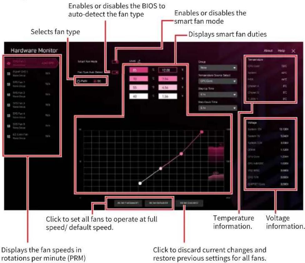

The appearance of this menu may differ based on your motherboard model. Please consult your motherboard's BIOS for specific settings and options.
- Please follow the steps below to adjust fan speed (PRM).
- Selects a fan you want to adjust.
- Click and drag the duty points on the graph to adjust the desired fan speed (RPM).

- Please follow the steps below to add new fan duty for smart fan mode
- Select a fan you want to adjust.
- Double-click the icon next to Level.
- Choose a temperature source for this fan duty point.
- Enter a desired value within the smart mode range. Then click the “+” to add the new fan duty.


Make sure fans are working properly after adjusting the fan speed and switching the fan mode.
BIOS Log
The BIOS log page displays a detailed list of BIOS configuration modifications during this period.
Click this icon to enter the BIOS log page.

Language
Click on this button to select the display language of the BIOS setup program.

BIOS Search
Click this icon to enter BIOS serach page

On the search page, it allows you to search for the related BIOS items by entering the keyword.
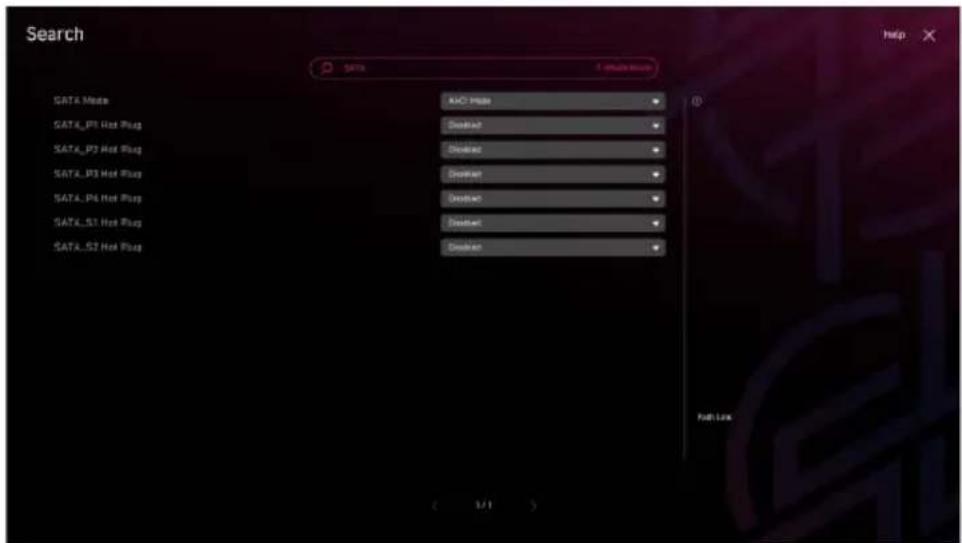

On the search page, only the F2, F6, F10 and F12 function keys are available.
Screenshot
Click on this button or press the F12 key to take a screenshot and save it to a USB flash drive (FAT/ FAT32 format only).
Click this icon to take a screenshot

Boot priority
Drag and drop the icons to set the boot order of devices. Devices from left to right will have boot priority in descending order (highest on the left).

Boot device priority bar
EZ On/Off
The Ez On/Off section provides easy-to-use controls for common functions.

EZ setup swtiches
•CPU Fan Fail Warning Control - enables or disables the system to show the CPU fan fail warning message during the POST.
•Temperature Unit - change the temperature unit.
- fTPM 2.0 - enables or disables the firmware TPM control.
•EZ LED Control - turns on or off all the LEDs of the motherboard.
- ErP Ready - enables or disables the system power consumption according to ErP regulation.
- Debug Code LED Control - enables or disables the debug code LED.

The appearance of this menu may differ based on your motherboard model. Please consult your motherboard's BIOS for specific settings and options.
EZ Config
The EZ Config section provides some specific BIOS setting shortcuts for quick accessing.
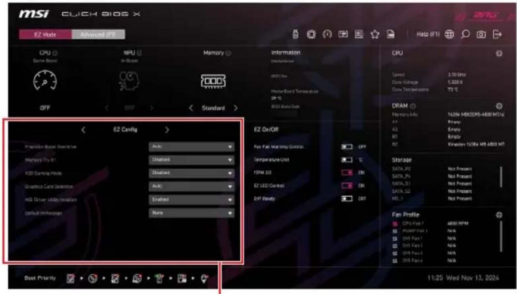
EZ Config menu
Within the EZ Config section, click the < or > icon next to EZ Config label to switch between EZ Config menu and Favorites menu.
Advanced Mode
In Advanced mode, it provides detailed BIOS settings for experienced users to fine-tune performance and overclocking.
Selects BIOS setting mode. Or press F7 to change setting mode.

The left side of the BIOS screen displays several BIOS menus, including the following items:
- System Status - This menu displays comprehensive system information and allows you to adjust system date and time settings.
- Advanced - This menu allows you to specify the parameters and adjust settings for the devices and components of your system.
•Overclocking - This menu allows you to adjust the frequency and voltage. Remember, higher settings can mean better performance, but also raise the risk of damage.
- Security - This menu allows you to set administrator and user passwords, and manage TPM settings for enhanced system security using this menu.
- Boot - This menu allows you to set the system boot devices.
- Save & Exit - This menu provides options for restoring default settings, saving customized settings, or discarding any unsaved changes.
System Status
The System Status menu allows you to set the system clock and view system information.

- System Date
Sets the system date. Use Tab key to switch between date elements.
The format is
System Time
Sets the system time. Use tab key to switch between time elements. The time format is
▶ SATA PortX/ M2_X
Shows the information of connected SATA/ M.2 devices.

If the connected SATA/ M.2 device is not displayed, turn off computer and re-check SATA/ M.2 cable and power cable connections of the device and motherboard.
- System Information
Shows detailed system information, including CPU type, BIOS version, and Memory information. (Read only).
▶ DMI Information
Shows system information, desktop Board Information and chassis Information. (Read only).
Advanced
The Advanced menu allows you to adjust and set the parameters and behaviors of PCIe, ACPI, integrated peripherals, integrated graphics, USB, power management and Windows.

- PCIe Sub-system Settings
Sets PCI, PCI express interface protocol and latency timer. Press Enter to enter the sub-menu.
▶ Re-Size BAR Support
Enables or disables the Resize BAR (Base Address Register) support. It is only available if the system supports 64-bit PCI/ PCIe decoding. If the system supports 64-bit PCI/ PCIe decoding, please enable this item for compatible PCIe device. It is a requirement by AMD Smart Access Memory (SAM) technology.
M.2_X Gen Mode
Sets PCI Express protocol for M.2_X slot to match different installed M.2 devices.
- PCI_Ex Gen Switch
Sets PCI Express protocol for PCI_E1 slot to match different installed PCIe devices.
▶ Chipset Gen Switch
Sets PCI Express protocol (from chipset) for matching different installed devices.
- PCI_Ex Lanes Configuration
PCIe lanes configuration is for MSI M.2 expansion card/ Other M.2 PCIe storage card. The options in this item will vary with the installed processor.
- ASPM Control for CPU PCIe
If enabled, ASPM will be controlled by the operating system. If disabled, ASPM will be controlled by the BIOS.
▶ SR-IOV Support
Enables or disables the SR-IOV (Single Root IO Virtualization) support.
▶ ACPI Settings
Sets ACPI parameters of onboard power LED behaviors. Press Enter to enter the sub-menu.
▶ Power LED
Sets shining behaviors of the onboard Power LED.
[Dual Color] The power LED turns to another color to indicate the S3 state.
[Blinking] The power LED blinks to indicate the S3 state.
▶ CPU Over Temperature Alert
Enables or disables the CPU overheating alert sound and message when CPU temperature is over 80 and 94 degrees centigrade.
- Integrated Peripherals
Sets integrated peripherals' parameters, such as LAN, HDD, USB and audio. Press Enter to enter the sub-menu.
▶ Graphics Card Detection
Allows the system to detect if there is any discrete graphics card or integrated graphics unit.
▶ Onboard LAN Controller
Enables or disables the onboard LAN controller.
▶ LAN Option ROM
Enables or disables the legacy network Boot Option ROM for detailed settings. This item will appear when Onboard LAN Controller is enabled. For CSM mode (Legacy) only.
[Enabled] Enables the onboard LAN Boot ROM.
[Disabled] Disables the onboard LAN Boot ROM.
▶ Network Stack
Sets UEFI network stack for optimizing IPv4 / IPv6 function. This item will appear when Onboard LAN Controller is enabled.
[Enabled] Enables UEFI network stack.
[Disabled] Disables UEFI network stack.
▶ Ipv4 PXE Support
When Enabled, the system UEFI network stack will support lpv4 protocol. This item will appear when Network Stack is enabled.
[Enabled] Enables the lpv4 PXE boot support.
[Disabled] Disables the lpv4 PXE boot support.
▶ Ipv6 PXE Support
When Enabled, the system UEFI network stack will support lpv6 protocol. This item will appear when Network Stack is enabled.
[Enabled] Enables the lpv6 PXE boot support.
[Disabled] Disables the lpv6 PXE boot support.
- Onboard Wi-Fi/BT Module Control
Enables or disables the onboard Wi-Fi and Bluetooth functions. If Auto, the both of Wi-Fi and bluetooth are be enabled.
▶ SATA Mode
Sets the operation mode of the onboard SATA controller.
[AHCI Mode] Specify the AHCI mode for SATA storage devices. AHCI (Advanced Host Controller Interface) offers some advanced features to enhance the speed and performance of SATA storage device, such as Native Command Queuing (NCQ) and hot-plugging.
[RAID Mode] Enables RAID function for SATA storage devices.
- Onboard E-SATA Controller Mode
Sets the operation mode of the onboard E-SATA controller.
▶ HD Audio Controller
Enables or disables the onboard High Definition Audio controller.
Smart Button
Sets the system operation function for the reset button of the case.
▶ Rear Smart Key
Sets the system operation function for the smart button on the rear I/O of the motherboard.
- Integrated Graphics Configuration
Adjusts integrated graphics settings for optimum system. Press Enter to enter the sub-menu. This sub-menu is only available with the CPU integrate with IGP.
- Initiate Graphic Adapter
Selects a graphics device as the primary boot device.
[IGD] Integrated Graphics Display.
[PEG] PCI-Express Graphics Device.
▶ Integrated Graphics
This item allows you to set the UMA memory size manually or allows the system to allocate the system memory dynamically for integrated graphics.
▶ UMA Frame Buffer Size
Sets the system memory buffer size for onboard integrated graphics.
▶ Hyper Graphics
Enables or disables the Hyper Graphics technology.
USB Configuration
Sets the onboard USB controller and device function. Press Enter to enter the submenu.
- XHCI Hand-off
Enables or disables XHCI hand-off support for the operating system without XHCI hand-off feature.
▶ Legacy USB Support
Sets Legacy USB function support.
[Auto] The system will automatically detect if any USB device is connected and enable the legacy USB support.
[Enabled] Enable the USB support under legacy mode.
[Disabled] The USB devices will be unavailable under legacy mode.
- Super IO Configuration
Sets system Super I/O chip parameters including LPT and COM ports. Press Enter to enter the sub-menu.
- Serial (COM) Port 0/1 Configuration
Sets detailed configuration of serial(COM) port 0/1. Press Enter to enter the submenu.
Serial (COM) Port 0/1
Enables or disables serial (COM) port 0/1.
- Serial (COM) Port 0/1 Settings
Sets serial (COM) port 0/1. If set to Auto, BIOS will optimize the IRQ automatically or you can set it manually.
▶ Parallel (LPT) Port Configuration
Sets detailed configuration of parallel port (LPT). Press Enter to enter the sub-menu.
▶ Parallel (LPT) Port
Enables or disables parallel(LPT) port.
▶ Parallel (LPT) Port Settings
Sets parallel port (LPT). If set to Auto, BIOS will optimize the IRQ automatically or you can set it manually.
▶ Device Mode
Selects an operating mode for parallel port.
[STD Printer Mode] Printer port mode
[SPP] Standard Parallel Port mode
[EPP-1.9 and SPP] Enhanced Parallel Port-1.9 mode + Standard Parallel Port mode.
Power Management Setup
Sets system Power Management of ErP and AC Power Loss behaviors. Press Enter to enter the sub-menu.
▶ ErP Ready
Enables or disables the system power consumption according to ErP regulation.
[Enabled] Optimize the system power consumption according to ErP regulation. It will not support S4 & S5 wake up by USB, PCI and PCIe devices.
[Disabled] Disables this function.
- Restore after AC Power Loss
Sets the system behaviors while encountering the AC power loss.
[Power Off] Leaves the system in power off state after restoring AC power.
[Power On] Boot up the system after restoring AC power.
[Last State] Restores the system to the previous state (power on/ power off) before AC power loss.
- System Power Fault Protection
Enables or disables the system to boot up when detecting abnormal voltage input.
[Enabled] Protect the system from unexpected power operating and remain the shut down status.
[Disabled] Disables this function.
▶ BIOS UEFI/ CSM Mode
Select CSM (Compatibility Support Module) or UEFI mode to meet the system requirement.
[CSM] For the non-UEFI driver add-on devices or non-UEFI mode OS.
[UEFI] For the UEFI driver add-on devices and UEFI mode OS.
- Wake Up Event Setup
Sets system wake up behaviors for different sleep modes. Press Enter to enter the sub-menu.
▶ Wake Up Event By
Selects the wake up event by BIOS or operating system.
[BIOS] Activates the following items, set wake up events of these items.
[OS] The wake up events will be defined by OS.
- Resume By RTC Alarm
Disables or enables the system wake up by RTC Alarm.
[Enabled] Enables the system to boot up on a scheduled time/date.
[Disabled] Disables this function.
- Date (of month) Alarm/ Time (hh:mm:ss) Alarm
Sets RTC alarm date/ Time. If Resume By RTC Alarm is set to [Enabled], the system will automatically resume (boot up) on a specified date/hour/minute/second in these fields (using the + and - keys to select the date & time settings).
- Resume By PCI-E Device
Enables or disables the wake up function of installed PCI-E expansion cards.
[Enabled] Enables the system to be awakened from the power saving modes when activity or input signal of PCIe device is detected.
[Disabled] Disables this function.
- Resume by USB Device
Disables or enables system wake up from S3/S4 by USB device.
[Enabled] Enables the system to be awakened from sleep state when activity of USB device is detected.
[Disabled] Disables this function.
- Resume From S3/S4/S5 by PS/2 Mouse
Enables or disables the system wake up by PS/2 mouse.
[Enabled] Enables the system to be awakened from S3/ S4/ S5 state when activity of PS/2 mouse is detected.
[Disabled] Disables this function.
Resume From S3/S4/S5 by PS/2 Keyboard
Enables or disables the system wake up by PS/2 keyboard.
[Any Key] Enables the system to be awakened from S3/ S4/ S5 state when activity of any key on PS/2 keyboard is detected.
[Hot Key] Enables the system to be awakened from S3/ S4/ S5 state when activity of hot key on PS/2 keyboard is detected.
[Disabled] Disables this function.
Hot Key
Selects a combination of keys as a hot key to wake the system. This item appears when you set the Resume From S3/S4/S5 by PS/2 Keyboard to Hot Key.
- Click BIOS Configuration
Configures BIOS setup related items. Press Enter to enter the sub-menu.
- Slide Animation
Enables or disables the sliding function for BIOS main menu block.
▶ Default Homepage
Selects a BIOS menu as the BIOS main page.
▶ Show Application At First Time
Selects an application to launch when entering BIOS menu at the next startup.
- Secure Erase+
Enables or disables Secure Erase+ function. Secure Erase+ is the best way to effectively wipe all data from a SSD. Please note that data of SSD will be erased after enabling Secure Erase+.
▶ MSI Driver Utility Installer
Enables or disables MSI driver utility installer support.
- NVME SSD Self-Test
This setting enables or disables a built-in diagnostic function within the NVMe SSD. Press Enter to start the NVME SSD self test.
- SR-IOV Support
Enables or disables the Intel SR-IOV (Single Root I/O Virtualization).
M.2 XPANDER Card Settings
You can set the fan duty percentage according LED color of the M.2 XPANDER card fan. If set to Auto, BIOS will set the fan duty automatically.
▶ Realtek PCIe GBE Family Controller (MAC
Shows driver information and configuration of the ethernet controller parameter. This item will appear when Network Stack is enabled.
- RAIDXpert2 Configuration Utility
RAIDXpert2 is a utility used for creating and managing NVMe RAID arrays. Press Enter to enter the sub-menu.
Overclocking menu
This menu allows you to configure the frequencies and voltages for overclocking. Please note that, higher frequency and voltage may benefit overclocking capability but cause system instability.


• Overclocking your system manually is only recommended for advanced users.
• Overclocking is not guaranteed, and if done improperly, it could void your warranty or severely damage your hardware.
- If you are unfamiliar with overclocking, we advise you to use Game Boost/ Creation Boost function or easy overclocking.
- The BIOS options and settings in Overclocking menu will vary from the motherboard you purchased. Please refer to the actual BIOS of your system for the BIOS settings and options.
OC Explore Mode
Enables or disables to show the normal or expert version of OC settings.
[Normal] Provides the regular OC settings in BIOS setup.
[Expert] Provides the advanced OC settings for OC expert to configure in BIOS setup.
- CPU Ratio Apply Mode
Sets applied mode for CPU ratio.
▶ CPU Ratio
Sets the CPU ratio that is used to determine CPU clock speed. This item will appear when CPU Ratio Apply Mode is set to All Core and if the processor supports this function.
- Adjusted CPU Frequency
Shows the adjusted CPU frequency. Read-only.
- CCD0 Ratio
Sets the CPU CCD0 ratio. This item will appear when CPU Ratio Apply Mode is set to Per CCD/ Adaptive.
- CCD1 Ratio
Sets the CPU CCD1 ratio. This item will appear when CPU Ratio Apply Mode is set to Per CCD/ Adaptive and if the processor supports this function.
▶ CPU CCD Voltage
Sets the CPU CCD voltage. This item will appear when CPU Ratio Apply Mode is set to Per CCD.
▶ Performance Switch
This item allows you to specify a level to upgrade the CPU performance based on the CPU quality. This item will appear when CPU Ratio Apply Mode is set to Adaptive.
▶ CPU Performance CCD0 Ratio
Sets the CPU CCD0 ratio. This item will appear when Performance Switch is set to Advanced.
▶ CPU Performance CCD1 Ratio
Sets the CPU CCD0 ratio. This item will appear when Performance Switch is set to Advanced and if the processor supports this function.
▶ Performance Current Limit
This item allows you to set the current limit. This item will appear when Performance Switch is set to Advanced.
▶ Performance Current Limit Hysteresis
This item allows you to set the current limit of hysteresis. This item will appear when Performance Switch is set to Advanced.
- Trigger Counts
This item allows you to set the time of each trigger count. This item will appear when Performance Switch is set to Advanced.
▶ CPU Performance Voltage
Sets the CPU CCD voltage. This item will appear when Performance Switch is set to Advanced.
- Advanced CPU Configuration
Press Enter to enter the sub-menu. You can set the parameters about CPU power/current/overclocking.

The system may become un-stable or un-bootable after changing the power parameters. If it occurs, please clear the CMOS data and restore the default settings.
▶ AMD Overclocking
Press Enter to enter the sub-menu. You can set the parameters about CPU overclocking. This sub-menu will appear when the CPU and chipset support this function.
▶ Manual iGPU Overclocking
Press Enter to enter the sub-menu.
▶ GFX Clock Frequency
Set the frequency of integrated graphics.
▶ GFX Voltage
Set the voltage of integrated graphics.
▶ Precision Boost Overdrive
Enables or disables Precision Boost Overdrive (PBO) that is a performance-maximizing technology available in AMD CPU. This item will appear only when the CPU supports this function.
▶ CCD0 Core Control
Specifies the number of cores to utilize for CCD0.
- CCD1 Core Control
Specifies the number of cores to utilize for CCD1.
▶ SMT Control
Enables or disables the symmetric multi-threading.
LN2 Mode
Enables or disables the LN2 mode. LN2 mode provides additional stability at extreme cold operating temperatures.
▶ LCLK Frequency Control (I/O Clock)
Sets this item to Manual allows you to set the LCLK frequency manually in the following item. If set to Auto, BIOS will configure the frequency automatically.
▶ Maximum Frequency
This item allows you to set the LCLK frequency manually. This item will appear when LCLK Frequency Control (I/O Clock) is set to Manual.
▶ Prochot VRM Throttling
Disabling Prochot prevents the VRM from throttling the CPU when overheating.
▶ Peak Current Control
Enables or disables the peak current control.
▶ PBO Limits
Sets the PBD limits control mode. This item will appear when Precision Boost Overdrive is set to Advanced.
▶ PPT Limit [W]
Sets PPT (Package Power Tracking) limit. This item will appear when PBO Limits is set to Manual.
▶ TDC Limit [A]
Sets TDC (Thermal Design Current) limit. This item will appear when PBO Limits is set to Manual.
▶ EDC Limit [A]
Sets EDC (Electrical Design Current) limit. This item will appear when PBO Limits is set to Manual.
▶ Precision Boost Overdrive Scalar Ctrl
Sets to control the PBO automatically or manually.
- Precision Boost Overdrive Scalar
Sets PBO scalar. This item will appear when Precision Boost Overdrive Scalar Ctrl is set to Manual.
▶ CPU Boost Clock Override
If enabled, it allows you to override the CPU boost clock. If set to Auto, BIOS will configure the clock. This item will appear when Precision Boost Overdrive is set to Advanced.
- Max CPU Boost Clock Override(+)
It allows you to increase the maximum CPU frequency that may be automatically achieved by the Precision Boost 2 algorithm.
- Max CPU Boost Clock Override(-)
It allows you to decrease the maximum CPU frequency that may be automatically achieved by the Precision Boost 2 algorithm.
▶ GPU Boost Clock Override
It allows you to set GPU boost clock. If set to Auto, BIOS will configure the clock.
- Max GPU Boost Clock Override
It allows you to set maximum GPU boost clock. If set to Auto, BIOS will configure the clock.
- Platform Thermal Throttle Limit
It allows you to set the maximum processor temperature. If set to Auto, BIOS will configure this settings. This item will appear when Precision Boost Overdrive is set to Advanced.
▶ GFX Curve Optimizer
Press Enter to enter the sub-menu. This item will appear when Precision Boost Overdrive is set to Advanced.
▶ GFX Curve Optimizer
Enables or disables the curve optimizer for integrated graphics.
▶ GFX Core Curve Optimizer Sign
Sets the shifting direction of the curve for integrated graphics. This item will appear when GFX Curve Optimizer is set to Enabled.
▶ GFX Curve Optimizer Magnitude
Sets Curve Optimizer value for all cores. This item will appear when GFX Curve Optimizer is set to Enabled.
▶ Curve Optimizer
Press Enter to enter the sub-menu. This item will appear when Precision Boost Overdrive is set to Advanced.
▶ Curve Optimizer
Enables or disables the Curve Optimizer for entire CPU cores or specific cores.
▶ All Core Curve Optimizer Sign
Sets the shifting direction of the curve for the entire CPU cores. This item will appear when Curve Optimizer is set to All Cores.
▶ All Core Curve Optimizer Magnitude
Sets Curve Optimizer value for the entire CPU cores. This item will appear when Curve Optimizer is set to All Cores.
- Core[n] Curve Optimizer Sign
Sets the shifting direction of the curve for specific cores. This item will appear when Curve Optimizer is set to Per Core.
- Core[n]s Curve Optimizer Magnitude
Sets Curve Optimizer value for specific cores. This item will appear when Curve Optimizer is set to Per Core.
▶ Curve Shaper
Press Enter to enter the sub-menu.
- Min Frequency - Low Temperature
Enables or disables the voltage offset under minimum frequency and low temperature conditions.
- Min Frequency - Low Temperature sign
Sets the direction of voltage offset under minimum frequency and low temperature conditions.
Min Frequency - Low Temperature Magnitude
Sets the value of voltage offset under minimum frequency and low temperature conditions.
- Min Frequency - Med Temperature
Enables or disables the voltage offset under minimum frequency and medium temperature conditions.
- Min Frequency - Med Temperature sign
Sets the direction of voltage offset under minimum frequency and medium temperature conditions.
- Min Frequency - Med Temperature Magnitude
Sets the value of voltage offset under minimum frequency and medium temperature conditions.
- Min Frequency - High Temperature
Enables or disables the voltage offset under minimum frequency and high temperature conditions.
- Min Frequency - High Temperature sign
Sets the direction of voltage offset under minimum frequency and high temperature conditions.
▶ Min Frequency - High Temperature Magnitude
Sets the value of voltage offset under minimum frequency and high temperature conditions.
- Low Frequency - Low Temperature
Enables or disables the voltage offset under low frequency and low temperature conditions.
- Low Frequency - Low Temperature sign
Sets the direction of voltage offset under low frequency and low temperature conditions.
- Low Frequency - Low Temperature Magnitude
Sets the value of voltage offset under low frequency and low temperature conditions.
▶ Low Frequency - Med Temperature
Enables or disables the voltage offset under low frequency and medium temperature conditions.
- Low Frequency - Med Temperature sign
Sets the direction of voltage offset under low frequency and medium temperature conditions.
▶ Low Frequency - Med Temperature Magnitude
Sets the value of voltage offset under low frequency and medium temperature conditions.
- Low Frequency - High Temperature
Enables or disables the voltage offset under low frequency and high temperature conditions.
- Low Frequency - High Temperature sign
Sets the direction of voltage offset under low frequency and high temperature conditions.
- Low Frequency - High Temperature Magnitude
Sets the value of voltage offset under low frequency and high temperature conditions.
▶ Med Frequency - Low Temperature
Enables or disables the voltage offset under medium frequency and low temperature conditions.
▶ Med Frequency - Low Temperature sign
Sets the direction of voltage offset under medium frequency and low temperature conditions.
Med Frequency - Low Temperature Magnitude
Sets the value of voltage offset under medium frequency and low temperature conditions.
Enables or disables the voltage offset under medium frequency and medium temperature conditions.
▶ Med Frequency - Med Temperature sign
Sets the direction of voltage offset under medium frequency and medium temperature conditions.
▶ Med Frequency - Med Temperature Magnitude
Sets the value of voltage offset under medium frequency and medium temperature conditions.
▶ Med Frequency - High Temperature
Enables or disables the voltage offset under medium frequency and high temperature conditions.
▶ Med Frequency - High Temperature sign
Sets the direction of voltage offset under medium frequency and high temperature conditions.
▶ Med Frequency - High Temperature Magnitude
Sets the value of voltage offset under medium frequency and high temperature conditions.
▶ High Frequency - Low Temperature
Enables or disables the voltage offset under high frequency and low temperature conditions.
▶ High Frequency - Low Temperature sign
Sets the direction of voltage offset under high frequency and low temperature conditions.
- High Frequency - Low Temperature Magnitude
Sets the value of voltage offset under high frequency and low temperature conditions.
▶ High Frequency - Med Temperature
Enables or disables the voltage offset under high frequency and medium temperature conditions.
▶ High Frequency - Med Temperature sign
Sets the direction of voltage offset under high frequency and medium temperature conditions.
▶ High Frequency - Med Temperature Magnitude
Sets the value of voltage offset under high frequency and medium temperature conditions.
▶ High Frequency - High Temperature
Enables or disables the voltage offset under high frequency and high temperature conditions.
▶ High Frequency - High Temperature sign
Sets the direction of voltage offset under high frequency and high temperature conditions.
▶ High Frequency - High Temperature Magnitude
Sets the value of voltage offset under high frequency and high temperature conditions.
▶ Maximum Frequency - Low Temperature
Enables or disables the voltage offset under maximum frequency and low temperature conditions.
▶ Maximum Frequency - Low Temperature sign
Sets the direction of voltage offset under maximum frequency and low temperature conditions.
▶ Maximum Frequency - Low Temperature Magnitude
Sets the value of voltage offset under maximum frequency and low temperature conditions.
▶ Maximum Frequency - Med Temperature
Enables or disables the voltage offset under maximum frequency and medium temperature conditions.
▶ Maximum Frequency - Med Temperature sign
Sets the direction of voltage offset under maximum frequency and medium temperature conditions.
▶ Maximum Frequency - Med Temperature Magnitude
Sets the value of voltage offset under maximum frequency and medium temperature conditions.
▶ Maximum Frequency - High Temperature
Enables or disables the voltage offset under maximum frequency and high temperature conditions.
▶ Maximum Frequency - High Temperature sign
Sets the direction of voltage offset under maximum frequency and high temperature conditions.
▶ Maximum Frequency - High Temperature Magnitude
Sets the value of voltage offset under maximum frequency and high temperature conditions.
▶ AMD CBS
Press Enter to enter the sub-menu. This sub-menu will appear when the CPU supports this function.
▶ SMT Control
Enables or disables the symmetric multi-threading.
- Core Performance Boost
Enables or disables the Core Performance Boost (CPB). This item appears when the installed CPU supports CPB.
[Auto] Allows the processor to dynamically overclocking when the system request the highest performance state.
[Disabled] Disables this function.
▶ Global C-state Control
Enables or disables IO based C-state generation and DF C-states.
▶ Opcache Control
Enables or disables opcache control.
▶ SVM Enable
Enables or disables the AMD SVM (Secure Virtual Machine) Mode.
▶ Power Supply Idle Control
Manages the behavior of power supply to prevent issues during idle states.
▶ AMD CBS - DF Common Options
▶ ACPI SRAT L3 Cache As NUMA Domain
Enables or disables each L3 cache as the independent NUMA domain.
- AMD CBS - NBIO Common Options
▶ IOMMU
Enables or disables the IOMMU (I/O Memory Management Unit) for I/O virtualization.
- PCIe ARI Support
Enables or disables the ARI (Alternative Routing ID Interpretation) support.
- PCIe ARI Enumeration
Enables or disables the ARI (Alternative Routing ID Interpretation) enumeration.
▶ PSPP Policy
Sets the PCIe Speed Power Policy (PSPP).
▶ AMD CBS - SMU Common Options
- System Configuration
Tune the system's TDP.
▶ STAPM
Enables or disables the STAPM (Skin Temperature Aware Power Management).
▶ SPL Control
This item allows you to set the SPL (Sustained Power Limit) manually or the SPL is configured by BIOS automatically.
- Sustained Power Limit
Set the sustained power limit.
▶ TDP Control
This item allows you to set the TDP manually or the TDP is configured by BIOS automatically.
▶ TDP
Sets the TDP value. This item will appear when TDP Control is set to Manual.
▶ PPT Control
This item allows you to set the PPT (Package Power Tracking) manually or the PPT is controlled by BIOS automatically.
▶ Fast PPT Limit
Sets the fast PPT (Package Power Tracking) value. This item will appear when PPT Control is set to Manual.
▶ Slow PPT Limit
Sets the slow PPT (Package Power Tracking) value. This item will appear when PPT Control is set to Manual.
▶ Slow PPT Time Constant
Sets the slow PPT (Package Power Tracking) time constant. This item will appear when PPT Control is set to Manual.
▶ PPT
Sets the PPT value. This item will appear when PPT Control is set to Manual.
▶ Thermal Control
This item allows you to set the Tcl limit temperature manually or the temperature is controlled by BIOS automatically.
▶ TjMax
Sets the maximum Tctl limit temperature value. This item will appear when Thermal Control is set to Manual.
▶ TDC Control
This item allows you to set the TDC (Thermal Design Current) manually or the TDC is configured by BIOS automatically.
TDC_VDDCR_VDD
Sets the VDDCR_VDD TDC limit. This item will appear when TDC Control is set to Manual.
▶ TDC_VDDCR_SOC
Sets the VDDCR_SOC TDC limit. This item will appear when TDC Control is set to Manual.
▶ EDC Control
This item allows you to set the EDC (Electrical Design Current) manually or the TDC is configured by BIOS automatically.
▶ EDC_VDDCR_VDD
Sets the VDDCR_VDD EDC limit. This item will appear when EDC Control is set to Manual.
▶ EDC_VDDCR_SOC
Sets the VDDCR_SOC EDC limit. This item will appear when EDC Control is set to Manual.
▶ PROCHOT Control
This item allows you to set the PROCHOT deassertion ramp time manually. If set to Auto, the default PROCHOT deassertion ramp time is enabled.
▶ PROCHOT Deassertion Ramp Time
Sets the PROCHOT deassertion ramp time. PROCHOT Deassertion Ramp Time is the time definition for the processor to return to normal power again after the PROCHOT overheating signal occurs.
▶ VDDP Voltage Control
This item allows you to control the manually or the TDC is controlled by BIOS automatically.
▶ VDDP Voltage
Sets the VDDP voltage. This item will appear when VDDP Voltage Control is set to Manual.
▶ Infinity Fabric Frequency and Dividers
Sets the infinity fabric frequency (FCLK) and dividers. If set to Auto, BIOS will configure the frequency.
- AMD CBS - SOC Miscellaneous Control
- Mixed DIMM config extended NUMA domain
Enables or disables the mixed DIMMs configuration to extended UNMA domain.
- Config TDP
Selects one group of the specified values for TDP (W), PPT (W), TDC (A), and EDC (A). If set to Auto, BIOS will configure the default values automatically.
▶ PSS Support
Enables or disables the generation of ACPI_PPC, _PSS, and _PCT objects.
▶ PPC Adjustment
Sets the P-state mode. This item will appear when PSS Support is set to Enabled.
▶ AVX Control
Enables or disables the AVX control.
- AVX2 Control
Enables or disables the AVX2 control.
▶ AVX512 Control
Enables or disables the AVX512 control. This item would be available after the AVX2 Control sets to Auto.
▶ FCH Spread Spectrum
Enables or disables the FCH spread spectrum. If set to Auto, BIOS will configure the setting automatically.
[Enabled] Enables the spread spectrum function to reduce the EMI (Electromagnetic Interference) problem.
[Disabled] Enhances the overclocking ability of CPU Base clock.

Remember to disable Spread Spectrum if you are overclocking because even a slight jitter can introduce a temporary boost in clock speed which may just cause your overclocked processor to lock up.
eCLK Mode
This allows you to set the CPU clock and PCIe clock synchronously or not. If set to Auto, BIOS will configure this setting automatically.
▶ CPU/ PCIe Base Clock (MHz)
This allows you to set the base clock of the CPU and PCIe synchronously. This item will appear when eCLK is set to eCLK0.
▶ CPU Base Clock (MHz)
Sets the CPU base clock. You may overclock the CPU by adjusting this item. Please note that overclocking behavior and stability is not guaranteed. This item will appear when eCLK is set to eCLK1.
▶ CPU Base Clock Apply Mode
Sets the applying mode for adjusted CPU base clock. This item will appear when eCLK is set to eCLK1.
[Auto] This setting will be configured automatically by BIOS.
[Next Boot] CPU will run the adjusted CPU base clock next boot.
[Immediate] CPU runs the adjusted CPU base clock immediately.
▶ CPU Base Clock Offset
Sets the offset value for CPU base clock. If set to Auto, BIOS will configure this setting automatically.
- Direct OC Button
Specifies the base clock or the CPU ratio for the OC button/ header to overclock CPU in real time.
- Direct OC Step (MHz)
Sets the increase or decrease value for base clock when press the OC button (+ or -) once.
▶ FCH Base Clock (MHz)
Sets the FCH base clock. Please note that overclocking behavior and stability is not guaranteed. If set to Auto, BIOS will configure this setting automatically.
▶ Optimized Performance Profile
AMD OPP (Optimized Performance Profile) is designed for RAM modules using Hynix chips, providing few overclocking profiles. This item is available only when the installed memory modules support this function.
A-XMP
Selects and loads memory XMP profile with optimized timing and voltage settings supported by installed memory module. This item is available only when the installed processor, memory modules and motherboard support this function.
EXPO
Selects and loads memory EXPO profile with optimized timing and voltage settings supported by installed memory module. This item is available only when the installed processor, memory modules and motherboard support this function.
▶ DRAM Speed
Sets the DRAM speed. Please note the overclocking behavior is not guaranteed.
- Adjusted DRAM Speed
Shows the adjusted DRAM speed. Read-only.
▶ FCLK Frequency
Sets the FCLK frequency (Internal Data Fabric clock of DRAM). Please note the overclocking behavior is not guaranteed.
▶ Fclk VDCI Mode Pref P0
Sets the FCLK VDCI (Voltage Dependent Clock Increment) mode in P0 state.
▶ UCLK DIV1 MODE
Sets UCLK (Internal memory controller clock) mode.
▶ High-Efficiency Mode
Enabling this feature will provide optimized settings and better memory performance.
▶ Memory Try It!
It can improve memory compatibility or performance by choosing optimized memory preset.
Enables or disables the memory context restoring. If enabled, the POST latency will be minimized.
- Advanced DRAM Configuration
Press Enter to enter the sub-menu. User can set the memory timing for each/ all memory channel. The system may become un-stable or un-bootable after changing memory timing. If it occurs, please clear the CMOS data and restore the default settings. (Refer to the Clear CMOS jumper section to clear the CMOS data, and enter the BIOS to load the default settings.)
▶ A-XMP User Profile
Press Enter to enter the sub-menu.
▶ A-XMP User Profile DIMMA1/ A2/ B1/ B2
Press Enter to enter the sub-menu. You can set memory profile manually.
▶ Load Setting To Item
Load the current settings or the A-XMP profile to the user profile.
▶ Write User Profile To Memory
Write the user profile to memory or erase the user profile from memory.
- Save Memory User Profile To BIOS
Save the user profile to BIOS.
▶ Load BIOS User Profile To Item
Load the user profile to the selected item.
▶ A-XMP User Profile 1/2
▶ DRAM Speed
Sets the DRAM speed for A-XMP user profile 1/2.
▶ DRAM Voltage
Sets the DRAM voltage for A-XMP user profile 1/2.
▶ DRAM VDDQ Voltage
Sets the DRAM VDDQ voltage for A-XMP user profile 1/2.
▶ DRAM VPP Voltage
Sets the DRAM VPP voltage for A-XMP user profile 1/2.
▶ Memory Controller Voltage
Sets the memory controller voltage for A-XMP user profile 1/2.
▶ tCL
Sets the CAS (Column Address Strobe) latency time for A-XMP user profile 1/2.
▶ tRCD
Sets the RAS to CAS delay time for A-XMP user profile 1/2.
▶ tRP
Sets the row pre-charge time for A-XMP user profile 1/2.
▶ tRAS
Sets the RAS (Row Address strobe) active time for A-XMP user profile 1/2.
▶ tRC
Sets the Active to Active/ Refresh delay time for A-XMP user profile 1/2.
▶ tWR
Sets the write recover time for A-XMP user profile 1/2.
▶ tRFC1
Sets the refresh recovery delay time for A-XMP user profile 1/2.
▶ tRFC2
Sets the refresh recovery delay time for A-XMP user profile 1/2.
▶ tRFCSB
Sets the refresh recovery delay time for A-XMP user profile 1/2.
▶ Command Rate
Sets the command rate for A-XMP user profile 1/2.
EXPO User Profile
Press Enter to enter the sub-menu.
- EXPO User Profile DIMMA1/ A2/ B1/ B2
Press Enter to enter the sub-menu. You can set memory profile manually.
- Load Setting To Item
Load the current settings or the EXPO profile to the user profile.
▶ Write User Profile To Memory
Write the user profile to memory or erase the user profile from memory.
- Save Memory User Profile To BIOS
Save the user profile to BIOS.
▶ Load BIOS User Profile To Item
Load the user profile to the selected item.
▶ DRAM Speed
Sets the DRAM speed for EXPO user profile 1/2.
▶ DRAM Voltage
Sets the DRAM voltage for EXPO user profile 1/2.
▶ DRAM VDDQ Voltage
Sets the DRAM VDDQ voltage for EXPO user profile 1/2.
▶ DRAM VPP Voltage
Sets the DRAM VPP voltage for EXPO user profile 1/2.
▶ tCL
Sets the CAS (Column Address Strobe) latency time for EXPO user profile 1/2.
▶ tRCD
Sets the RAS to CAS delay time for EXPO user profile 1/2.
▶ tRP
Sets the row pre-charge time for EXPO user profile 1/2.
▶ tRAS
Sets the RAS (Row Address strobe) active time for EXPO user profile 1/2.
▶ tRC
Sets the Active to Active/ Refresh delay time for EXPO user profile 1/2.
▶ tWR
Sets the write recover time for EXPO user profile 1/2.
▶ tRFC1
Sets the refresh recovery delay time for EXPO user profile 1/2.
▶ tRFC2
Sets the refresh recovery delay time for EXPO user profile 1/2.
▶ tRFCSB
Sets the refresh recovery delay time for EXPO user profile 1/2.
▶ Main Timing Configuration
▶ tCL
Sets the CAS (Column Address Strobe) latency time.
▶ tRCD
Sets the RAS to CAS delay time.
▶ tRP
Sets the row pre-charge time.
▶ tRAS
Sets the RAS (Row Address strobe) active time.
▶ tRC
Sets the Active to Active/ Refresh delay time.
▶ tWR
Sets the minimum write recover time.
▶ tRFC1
Sets the refresh recovery delay time.
▶ tRFC2
Sets the refresh recovery delay time.
▶ tRFCSB
Sets the refresh recovery delay time.
- Sub Timing Configuration
▶ tRTP
Sets read to pre-charge command delay time.
▶ tRRDL
Sets the activate to activate delay time for same bank group.
▶ tRRDS
Sets the activate to activate delay time for different bank groups.
▶ tFAW
Sets the time window in which four activates are allowed the same rank.
▶ tWTRL
Sets the internal write transaction to internal read command time for same bank group.
▶ tWTRS
Sets the internal write transaction to internal read command time for different bank groups.
▶ Turn Around Timing Configuration
▶ tRDRDSCL
Sets the CAS to CAS delay time for same bank group.
▶ tRDRDSC
Sets the read to read turnaround time in the same chip select.
▶ tRDRDSD
Sets the read to read turnaround time in the same DIMM.
▶ tRDRDDD
Sets the read to read turnaround time in the different DIMM.
▶ tWRWRSCL
Sets the write to write turnaround time for same bank group.
▶ tWRWRSC
Sets the write to write turnaround time in the same chip select.
▶ tWRWRSD
Sets the write to write turnaround time in the same DIMM.
▶ tWRWRDD
Sets the write to write turnaround time in the different DIMM.
▶ tWRRD
Sets the write to read turnaround time.
▶ tRDWR
Sets the read to write turnaround time.
▶ Misc item
▶ Power Down Enable
Enables or disables DDR power down mode.
▶ Gear Down Enable
Enables or disables the DDR gear down mode.
▶ ECC
Enables or disables DRAM ECC.
TSME
Enables or disables TSME feature (Transparent Secure Memory Encryption).
Data Scramble
Enables or disables data scrambling.
▶ Chipset Interleaving
This item allows you to set the interleave memory blocks across DRAM chip selects for node 0.
- Address Hash Bank
Enables or disables the bank address hashing.
- Address Hash CS
Enables or disables the CS address hashing.
▶ Bank Swap Mode
Selects the bank swap mode.
▶ DFE Read Training
Perform 2D Read Training with DFE.
▶ PPT Control
Enables or disables the PPT control.
- DDR Bus Configuration
- Processor CS drive strengths
Selects the drive strength for processor CS.
- Processor CK drive strengths
Selects the drive strength for processor CK.
▶ Processor CA drive strengths
Selects the drive strength for all CA0-13 IOs.
- Processor DQ drive strengths
Selects the drive strength for all DQ and DMI IOs.
- Processor DOT impedance
Selects the DOT impedance for all DBYTE IOs.
▶ Processor CA DOT impedance
Selects the DOT impedance for ACHAN CA IOs.
- Processor CK DOT impedance
Selects the DOT impedance for ACHAN CK IOs.
Selects the pull up impedance for processor ODT.
- Processor ODT impedance Pull Down p0
Selects the pull down impedance for processor ODT.
▶ Processor DQ drive strengths Pull Up P0
Selects the pull up drive strength for processor DQ.
- Processor DQ drive strengths Pull Down P0
Selects the pull down drive strength for processor DQ.
▶ Dram DQ driver strengths
Selects the DRAM drive strength for all DQ and DMI IOs.
▶ Dram DOT impedance RTT_NOM_WR
Selects the DRAM on-die termination impedance for RTT_NOM_WR.
▶ Dram DOT impedance RTT_NOM_RD
Selects the DRAM on-die termination impedance for RTT_NOM_RD.
▶ Dram DOT impedance RTT_WR
Selects the DRAM on-die termination impedance for RTT_WR.
▶ Dram DOT impedance RTT_PARK
Selects the DRAM on-die termination impedance for RTT_PARK.
▶ Dram DOT impedance DQS RTT_PARK
Selects the DRAM on-die termination impedance for DQS_RTT_PARK.
▶ Dram DQ driver strengths Pull Up P0
Selects the pull up DRAM drive strength for DRAM DQ.
▶ Dram DQ driver strengths Pull Down P0
Selects the pull down DRAM drive strength for DRAM DQ.
▶ Dram DOT impedance RTT_NOM_WR P0
Selects the DRAM on-die termination impedance for RTT_NOM_WR.
▶ Dram DOT impedance RTT_NOM_RD P0
Selects the DRAM on-die termination impedance for RTT_NOM_RD.
▶ Dram DOT impedance RTT_WR P0
Selects the DRAM on-die termination impedance for RTT_WR.
▶ Dram ODT impedance RTT_PARK P0
Selects the DRAM on-die termination impedance for RTT_PARK.
▶ Dram ODT impedance DQS_RTT_PARK P0
Selects the DRAM on-die termination impedance for DQS_RTT_PARK.
▶ DDR PMU Training
Read Preamble P0
Select the read preamble clock cycle.
▶ Write Preamble P0
Select the write preamble clock cycle.
▶ PHY VrefDAC0 P0
Set reference voltage for DAC0 PHY in P0 state.
▶ PHY VrefDAC1 P0
Set reference voltage for DAC1 PHY in P0 state.
▶ PMU DQ Vref P0
Set reference voltage of PMU DQ in P0 state.
▶ DDR Turnaround Times
▶ Read Drift Adjustment
Set the read drift time.
▶ Write Drift Adjustment
Set the write drift time.
- DigitALL Power
Press Enter to enter the sub-menu. Controls the digital powers related to CPU PWM.
▶ CPU Loadline Calibration Control
The CPU voltage will decrease proportionally according to CPU loading. Higher load-line calibration could get higher voltage and good overclocking performance, but increase the temperature of the CPU and VRM. If set to Auto, BIOS will configure this setting automatically.
▶ CPU Over Voltage Protection
Sets the voltage limit for CPU over-voltage protection. If set to Auto, BIOS will configure this setting automatically. Higher voltage provides less protection and may damage the system.
▶ CPU Under Voltage Protection
Sets the voltage limit for CPU under-voltage protection. If set to Auto, BIOS will configure this setting automatically. Higher voltage provides less protection and may damage the system.
▶ CPU Over Current Protection
Sets the current limit for CPU over-current protection. If set to Auto, BIOS will configure this setting automatically.
[Auto] This setting will be configured automatically by BIOS.
[Enhanced] Extends the current range for over-current protection.
▶ CPU Switching Frequency
Sets the PWM working speed to stabilize CPU Core voltage and minimize ripple range. Increasing the PWM working speed will cause higher temperature of MOSFET. So please make sure a cooling solution is well-prepared for MOSFET before you increase the value. If set to Auto, BIOS will configure this setting automatically.
▶ CPU VRM Over Temperature Protection
Sets the temperature limit on CPU VRM for over-temperature protection. The CPU frequency may be throttled when CPU temperature over the specified temperature. If set to Auto, BIOS will configure this settings.
▶ CPU NB/SoC Loadline Calibration Control
The CPU NB/SoC voltage will decrease proportionally according to CPU-NB loading. Higher load-line calibration could get higher voltage and good overclocking performance, but increase the temperature. If set to Auto, BIOS will configure this setting automatically.
▶ CPU NB/SoC Over Current Protection
Sets the current limit for CPU NB/SoC over-current protection. If set to Auto, BIOS will configure this setting 0 automatically.
[Auto] This setting will be configured automatically by BIOS.
[Enhanced] Extends the current range for over-current protection.
▶ CPU NB/SoC Switching Frequency
Sets the PWM working speed to stabilize CPU NB/Soc voltage and minimize ripple range. Increasing the PWM working speed will cause higher temperature of MOSFET. So please make sure a cooling solution is well-prepared for MOSFET before you increase the value. If set to Auto, BIOS will configure this setting automatically.
▶ VR 12VIN OCP Expander
Expands the limitation of VR Over Current Protection with 12V input voltage. The higher expanding value indicates less protection. Therefore, please adjust the current carefully if needed, or it may damage the CPU/VR MOS. If set to "Auto", BIOS will configure this setting automatically.
▶ CPU Core Voltage
Sets the CPU Core voltage mode. If set to Auto, BIOS will configure this setting automatically.
[Auto] This setting will be configured automatically by BIOS.
[Override Mode] Allows you to set the voltage manually.
[Offset Mode] Allows you to set the offset voltage and select the voltage offset mode.
[AMD Overclocking] Sets the adaptive voltage automatically for optimizing the system performance.
[Override + Offset] Sets the voltage manually and allows you to set the offset voltage.
▶ Override CPU Core Voltage
It allows you to set CPU core voltage. If set to Auto, BIOS will set the voltage automatically. This item will appear when CPU Core Voltage sets to Override mode or AMD Overclock.
▶ CPU Offset Mode Mark
Sets the CPU offset mode. This item will appear when CPU Core Voltage sets to Offset mode or Override + Offset Mode.
▶ CPU Offset Voltage
Sets the CPU offset voltage. This item will appear when CPU Core Voltage sets to Offset mode or Override + Offset Mode.
▶ CPU NB/SoC Voltage
Sets the CPU NB/ SoC voltage mode. If set to Auto, BIOS will configure this setting automatically.
[Auto] This setting will be configured automatically by BIOS.
[Override Mode] Allows you to set the voltage manually.
[AMD Overclocking] Sets the adaptive voltage automatically for optimizing the system performance.
▶ Override CPU NB/SoC Voltage
Sets CPU NB/SoC voltage. If set to Auto, BIOS will set the voltage automatically. This item will appear when CPU NB/SoC Voltage sets to Override mode.
- SOC Voltage
Sets CPU VDD_SOC voltage. If set to Auto, BIOS will set the voltage automatically. This item will appear when CPU NB/SoC Voltage sets to AMD Overclocking.
▶ VDDG Voltage Control
▶ VDDG Voltage Control
Selects apply mode for all the VDDG related voltages.
▶ Global VDDG CCD Voltage
Sets the global VDDG CCD voltage. If set to Auto, BIOS will set the voltage automatically.
▶ Global VDDG IOD Voltage
Sets the global VDDG IOD voltage. If set to Auto, BIOS will set the voltage automatically.
- CCD0- CCD VDDG Voltage
Sets the VDDG CCD voltage for CCD0. If set to Auto, BIOS will set the voltage automatically.
- CCD0-IOD VDDG Voltage
Sets the VDDG IOD voltage for CCD0. If set to Auto, BIOS will set the voltage automatically.
- CCD1- CCD VDDG Voltage
Sets the VDDG CCD voltage for CCD1. If set to Auto, BIOS will set the voltage automatically.
- CCD1-IOD VDDG Voltage
Sets the VDDG IOD voltage for CCD1. If set to Auto, BIOS will set the voltage automatically.
▶ VDDP Voltage Control
▶ VDDP Voltage Control
If set to Auto, BIOS will set the voltage automatically. If set to Manual, you can set the voltage manually.
▶ VDDP Voltage Adjust
Sets CPU VDDP voltage. If set to Auto, BIOS will set the voltage automatically.
▶ VDD MISC Voltage
Sets CPU VDD MISC voltage. If set to Auto, BIOS will set the voltage automatically.
- DRAM High Voltage Mode
Enables or disables DRAM high voltage mode.
- DRAM Voltage
Sets DRAM voltage. If set to Auto, BIOS will set the voltage automatically.
- DRAM VDDQ Voltage
Sets the DRAM VDDQ voltage. If set to Auto, BIOS will set these voltages automatically.
▶ DRAM VPP Voltage
Sets DRAM VPP voltage. If set to Auto, BIOS will set the voltage automatically.
▶ CPU VDDIO Voltage
Sets CPU VDDIO voltage. If set to Auto, BIOS will set the voltage automatically. This item will be available when you set the DRAM Voltage manually.
▶ CPU 1P8 Voltage
Sets CPU 1P8 voltage. If set to Auto, BIOS will set the voltage automatically.
- Chipset Core Voltage
Sets chipset core voltage. If set to Auto, BIOS will set the voltage automatically.
Chipset 1P8 Voltage
Sets chipset 1P8 voltage. If set to Auto, BIOS will set the voltage automatically.
▶ Memory Changed Detect
Enables or disables the system to issue a warning message during boot when the memory has been replaced.
[Enabled] The system will issue a warning message during boot and then you have to load the default settings for new devices.
[Disabled] Disables this function and keeps the current BIOS settings.
▶ CPU Specifications
Press Enter to enter the sub-menu. This sub-menu displays the information of installed CPU. You can also access this information menu at any time by pressing [F4]. Read only.
▶ CPU Technology Support
Press Enter to enter the sub-menu. The sub-menu shows the key features of installed CPU. Read only.
▶ MEMORY-Z
Press Enter to enter the sub-menu. This sub-menu displays all the settings and timings of installed memory. You can also access this information menu at any time by pressing [F5].
▶ DIMMx Memory SPD
Press Enter to enter the sub-menu. The sub-menu displays the information of installed memory. Read only.
- XMP Support Information
Press Enter to enter the sub-menu. The sub-menu displays the X.M.P information of installed memory. Read only.
Security
Use this menu to set the administrator password and the user password for system security. This menu also allows you to set the TPM (Trusted Platform Module) function.

- Administrator Password
Sets administrator password for system security. User has full rights to change the BIOS items with administrator password. After setting the administrator password, the state of this item will show Installed.
- User Password
Sets User Password for system security. User has limited rights to change the BIOS items with user password. This item will be available when administrator password is set. After setting the user password, the state of this item will show Installed.
▶ Password Check
Selects a condition that will request the password.
[Setup] A password will be requested for entering the BIOS Setup.
[Boot] A password will be requested for booting the system.
▶ Password Protection
To maintain flexibility in password management, set the password protection to Normal to allow password removal via a CMOS reset or BIOS update. To enhance security and prevent unauthorized password clearing, set it to Enforce.

When selecting the Administrator / User Password items, a password box will appear on the screen. Type the password then press Enter. The password typed now will replace any previous set password from CMOS memory. You will be prompted to confirm the password. You may also press Esc key to abort the selection.
To clear a set password, press Enter when you are prompted to enter a new password. A message will confirm the password is being disabled. Once the password is disabled, you can enter the setup and OS without authorization.
▶ U-Key
Enables or disables the USB flash drive as a key.
▶ Make U-Key at
Specify a USB flash drive as a key to lock your computer. Only people with that specific USB flash drive can use the computer.
▶ U-Key Execution Level
Set Enforce, the system can be configured to lock when the USB security key is absent. However, the security setting can be reset to normal mode via a CMOS reset or BIOS update in case of a lost USB key.
- Trusted Computing
Sets TPM (Trusted Platform Module) function.
▶ Security Device Support
Enables or disables the TPM function to build the endorsement key for accessing the system.
▶ AMD fTPM switch
Selects TPM device. This item will appear when Security Device Support is enabled.
[AMD CPU fTPM] Select it for AMD Firmware TPM.
[AMD CPU fTPM Disabled] Select it for Discrete TPM.
▶ Active PCR Banks
Shows the current active PCR banks.
▶ Available PCR banks
Shows all available PCR banks.
▶ SHA256 PCR Banks
Enables or disables the SHA256 PCR bank.
▶ SHA384 PCR Banks
Enables or disables the SHA384 PCR bank.
▶ Pending operation
Sets the action of pending TPM operation.
[None] Discard the selection
[TPM Clear] Clear all data secured by TPM.
▶ Platform Hierarchy
Enables or disables the platform hierarchy.
Storage Hierarchy
Enables or disables the storage hierarchy.
▶ Endorsement Hierarchy
Enables or disables the endorsement hierarchy.
▶ Physical Presence Spec Version
Sets the version of the testing tool (HCK) in OS.
- Chassis Intrusion Configuration
Press Enter to enter the sub-menu.
▶ Chassis Intrusion
Enables or disables recording messages while the chassis is opened. This function is ready for the chassis equips a chassis intrusion switch.
[Enabled] Once the chassis is opened, the system will record and issue a warning message.
[Reset] Clear the warning message. After clearing the message, please return to Enabled or Disabled.
[Disabled] Disables this function.
- Secure Boot
Press Enter to enter the sub-menu.
- Secure Boot
Secure Boot function can be enabled only when the Platform Key(PK) is enrolled and running accordingly.
- Secure Boot Mode
Selects the secure boot mode. This item is to select how the secure boot keys be loaded. This item appears when "Secure Boot" is enabled.
[Standard] The system will automatically load the secure keys from BIOS.
[Custom] Allows user to configure the secure boot settings and manually load the secure keys.
- Secure Boot Preset
Set Hardware/OS Compatibility to support non-UEFI or non-compliant hardware/OS with optimized settings, or enforce Maximum Security to ensure complete validation of all system components.
▶ Key Management
Press Enter to enter the sub-menu. Manage the secure boot keys. This item will become available when “Secure Boot Mode” sets to Custom.
▶ Factory Key Provision
Enables or disables the factory default keys.
Allows you to install all factory default keys.
- Reset To Setup Mode
Allows you to delete all the Secure Boot keys from NVRAM.
▶ Enroll Efi Image
Allows the image to run in Secure Boot mode. Enroll SHA256 Hash certificate of a PE image into authorized signature database (db).
▶ Platform Key(PK)
The Platform Key (PK) can protect the firmware from any un-authenticated changes. The system will verify the PK before your system enters the OS. Platform Key (PK) is used for updating KEK.
▶ Key Exchange Keys (KEK)
Key Exchange Key (KEK) is used for updating DB or DBX.
▶ Authorized Signatures (db)
Authorized Signatures(DB) lists the signatures that can be loaded.
▶ Forbidden Signatures (dbx)
Forbidden Signatures (DBX) lists the forbidden signatures that are not trusted and cannot be loaded.
▶ Authorized TimeStamps (dbt)
Authorized TimeStamps (DBT) lists the the authentication signatures with authorization time stamps.
▶ OsRecovery Singnatures(dbr)
Lists the available signatures for OS recovery.
Boot
Sets the sequence of system boot devices.

- Full Screen Logo Display
Enables or disables to show the full screen logo while system POST.
[Enabled] Shows the logo in full screen.
[Disabled] Shows the POST messages.
- Bootup NumLock State
Select the keyboard NumLock state upon bootup.
▶ POST Beep
Enables or disables the POST beep.
▶ AUTO CLR_CMOS
Enables or disables the CMOS data to be resumed automatically when the system cannot boot to OS and reboot repeatedly.
- Boot Mode Select
Sets the system boot mode from legacy or UEFI architecture depending on OS installation requirement. This item will become un-selectable and will be configured automatically by BIOS when BIOS UEFI/CSM Mode sets to UEFI.
[UEFI] Enables UEFI BIOS boot mode support only.
[LEGACY+UEFI] Enables both Legacy BIOS boot mode and UEFI BIOS boot mode.
- FIXED BOOT ORDER Priorities
Sets device priority for system boot.
- Boot Option Priorities
These items are used to prioritize the installed boot devices.
Save & Exit
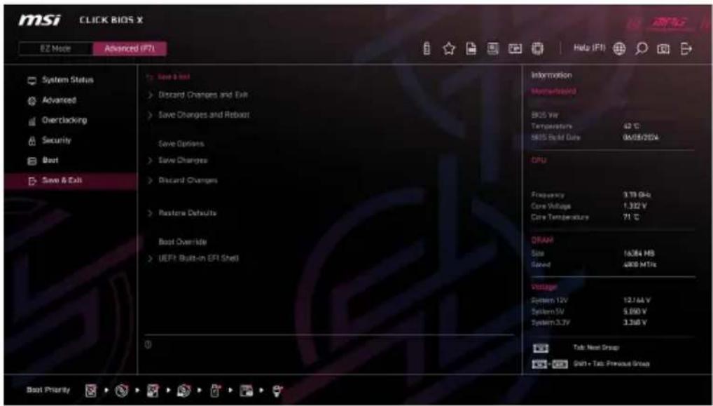
- Discard Changes and Exit
Exit BIOS setup without saving any change.
- Save Changes and Reboot
Save all changes and reboot the system.
- Save Changes
Save current changes.
- Discard Changes
Discard all changes and restore to the previous values.
- Restore Defaults
Restore or load all default values.
- Boot Override
The installed boot-able devices will appear on this menu, you can select one of them to be the boot device.
Resetting BIOS
If you encounter certain issues with your computer, restoring the default BIOS settings might help. You can reset the BIOS settings using the following methods:
- Enter the BIOS setup and press F6 to load the optimized defaults.
- Use the Clear CMOS jumper on the motherboard to reset the BIOS.
- If your motherboard has a Clear CMOS button on the rear I/O panel, press it to reset the BIOS.

Ensure the computer is powered off before clearing the CMOS data. For more details, refer to the Clear CMOS jumper/button section in the manual.
Updating BIOS
Updating BIOS with M-FLASH
Before starting the M-Flash process, make sure you have:
- A USB flash drive with a capacity of 32GB or less that is formatted to FAT32.

M-Flash only supports FAT32 format, and the USB flash drive should not exceed 32GB.
- A computer with internet access.
Please follow the steps below to update BIOS:
- Download the latest BIOS file from the MSI website that matches your motherboard model, and save it to the USB flash drive.
- If your motherboard has a Multi-BIOS switch, switch to the target BIOS ROM.
- Insert the USB flash drive into your motherboard's USB port.
-
Enter flash mode by either:
-
Rebooting and pressing Ctrl + F5 during POST, then clicking Yes to reboot the system.
-
Rebooting and pressing Del during POST to enter BIOS, then clicking the M-FLASH button and clicking Yes to reboot.
-
Select a BIOS file from the M-FLASH File menu and press Enter.
- When prompted by a File Check message, click Yes to start the BIOS update.
Once the update reaches 100%, the system will reboot automatically.
Updating the BIOS with MSI Center
Before updating:
- Ensure the LAN driver is installed, and the internet connection is working properly.
- Close all other applications before updating the BIOS.
To update BIOS:
- Install and launch MSI Center, then go to Support page.
- Select Live Update and click on Advance button.
- Select the BIOS file and click on Install button.
- The installation reminder will appear, then click the Install button.
The system will automatically restart to update the BIOS. Once the flashing process is complete, the system will restart.
Updating BIOS with Flash BIOS Button
- Download the latest BIOS file from the MSI website that matches your motherboard model.
- Rename the BIOS file to MSI.ROM, and save it to the root directory of a USB flash device.
- Connect the power supply to CPU_PWR1 and ATX_PWR1. (You don't need to install the CPU and memory.)
- Plug the USB flash device with the MSI.ROM file into the Flash BIOS Port on the rear I/O panel.
- Press the Flash BIOS Button to start flashing the BIOS. The LED will start flashing to indicate the process has begun.
The LED will turn off when the process is complete.
Copyright and Trademarks Notice
msi
MSI
微星
微星科技
MICRO-STAR INTERNATIONAL

Copyright © Micro-Star Int’ I Co., Ltd. All rights reserved. The MSI logo used is a registered trademark of Micro-Star Int’ I Co., Ltd. All other marks and names mentioned may be trademarks of their respective owners. No warranty as to accuracy or completeness is expressed or implied. MSI reserves the right to make changes to this document without prior notice.
Revision History
Version 1.0, 2024/09, First release
- BIOS SETUP
- UEFI BIOS
- UEFI ADVANTAGES
- INCOMPATIBLE UEFI CASES
- HOW TO FIND THE BIOS VERSION
- ENTERING BIOS SETUP
- FUNCTION KEY
- BIOS SETTING MODE
- EZ MODE
- GAME BOOST
- CREATION BOOST
- AI BOOST
- AXMP/ EXPO PROFILE
- M-FLASH
- FAVORITES
- MSI PERFORMANCE PRESET
- SMART BUTTON
- PROFILE
- HARDWARE MONITOR
- BIOS LOG
- LANGUAGE
- BIOS SEARCH
- SCREENSHOT
- BOOT PRIORITY
- EZ ON/OFF
- EZ CONFIG
- ADVANCED MODE
- SYSTEM STATUS
- SYSTEM DATE
- SYSTEM TIME
- SATA PORTX/ M2_X
- SYSTEM INFORMATION
- DMI INFORMATION
- ADVANCED
- PCIE SUB-SYSTEM SETTINGS
- RE-SIZE BAR SUPPORT
- M.2_X GEN MODE
- PCI_EX GEN SWITCH
- CHIPSET GEN SWITCH
- PCI_EX LANES CONFIGURATION
- ASPM CONTROL FOR CPU PCIE
- SR-IOV SUPPORT
- ACPI SETTINGS
- POWER LED
- CPU OVER TEMPERATURE ALERT
- INTEGRATED PERIPHERALS
- GRAPHICS CARD DETECTION
- ONBOARD LAN CONTROLLER
- LAN OPTION ROM
- NETWORK STACK
- IPV4 PXE SUPPORT
- IPV6 PXE SUPPORT
- ONBOARD WI-FI/BT MODULE CONTROL
- SATA MODE
- ONBOARD E-SATA CONTROLLER MODE
- HD AUDIO CONTROLLER
- REAR SMART KEY
- INTEGRATED GRAPHICS CONFIGURATION
- INITIATE GRAPHIC ADAPTER
- INTEGRATED GRAPHICS
- UMA FRAME BUFFER SIZE
- HYPER GRAPHICS
- USB CONFIGURATION
- XHCI HAND-OFF
- LEGACY USB SUPPORT
- SUPER IO CONFIGURATION
- SERIAL (COM) PORT 0/1 CONFIGURATION
- SERIAL (COM) PORT
- SERIAL (COM) PORT 0/1 SETTINGS
- PARALLEL (LPT) PORT CONFIGURATION
- PARALLEL (LPT) PORT
- PARALLEL (LPT) PORT SETTINGS
- DEVICE MODE
- POWER MANAGEMENT SETUP
- ERP READY
- RESTORE AFTER AC POWER LOSS
- SYSTEM POWER FAULT PROTECTION
- BIOS UEFI/ CSM MODE
- WAKE UP EVENT SETUP
- WAKE UP EVENT BY
- RESUME BY RTC ALARM
- DATE (OF MONTH) ALARM/ TIME (HH:MM:SS) ALARM
- RESUME BY PCI-E DEVICE
- RESUME BY USB DEVICE
- RESUME FROM S3/S4/S5 BY PS/2 MOUSE
- RESUME FROM S3/S4/S5 BY PS/2 KEYBOARD
- HOT KEY
- CLICK BIOS CONFIGURATION
- SLIDE ANIMATION
- DEFAULT HOMEPAGE
- SHOW APPLICATION AT FIRST TIME
- SECURE ERASE
- MSI DRIVER UTILITY INSTALLER
- NVME SSD SELF-TEST
- M.2 XPANDER CARD SETTINGS
- OVERCLOCKING MENU
- OC EXPLORE MODE
- CPU RATIO APPLY MODE
- CPU RATIO
- ADJUSTED CPU FREQUENCY
- AMD OVERCLOCKING
- MANUAL IGPU OVERCLOCKING
- GFX CLOCK FREQUENCY
- GFX VOLTAGE
- PRECISION BOOST OVERDRIVE
- CCD0 CORE CONTROL
- CCD1 CORE CONTROL
- SMT CONTROL
- LN2 MODE
- LCLK FREQUENCY CONTROL (I/O CLOCK)
- MAXIMUM FREQUENCY
- PROCHOT VRM THROTTLING
- PEAK CURRENT CONTROL
- PBO LIMITS
- PPT LIMIT [W]
- TDC LIMIT [A]
- EDC LIMIT [A]
- PRECISION BOOST OVERDRIVE SCALAR CTRL
- PRECISION BOOST OVERDRIVE SCALAR
- CPU BOOST CLOCK OVERRIDE
- MAX CPU BOOST CLOCK OVERRIDE(+)
- MAX CPU BOOST CLOCK OVERRIDE(-)
- GPU BOOST CLOCK OVERRIDE
- MAX GPU BOOST CLOCK OVERRIDE
- PLATFORM THERMAL THROTTLE LIMIT
- GFX CURVE OPTIMIZER
- GFX CORE CURVE OPTIMIZER SIGN
- GFX CURVE OPTIMIZER MAGNITUDE
- AMD CBS
- CORE PERFORMANCE BOOST
- GLOBAL C-STATE CONTROL
- OPCACHE CONTROL
- SVM ENABLE
- POWER SUPPLY IDLE CONTROL
- AMD CBS - DF COMMON OPTIONS
- ACPI SRAT L3 CACHE AS NUMA DOMAIN
- AMD CBS - NBIO COMMON OPTIONS
- IOMMU
- PCIE ARI SUPPORT
- PCIE ARI ENUMERATION
- PSPP POLICY
- AMD CBS - SMU COMMON OPTIONS
- SYSTEM CONFIGURATION
- STAPM
- SPL CONTROL
- SUSTAINED POWER LIMIT
- TDP CONTROL
- TDP
- PPT CONTROL
- FAST PPT LIMIT
- SLOW PPT LIMIT
- SLOW PPT TIME CONSTANT
- PPT
- THERMAL CONTROL
- TJMAX
- TDC CONTROL
- TDC_VDDCR_VDD
- TDC_VDDCR_SOC
- EDC CONTROL
- EDC_VDDCR_VDD
- EDC_VDDCR_SOC
- PROCHOT CONTROL
- PROCHOT DEASSERTION RAMP TIME
- VDDP VOLTAGE CONTROL
- VDDP VOLTAGE
- INFINITY FABRIC FREQUENCY AND DIVIDERS
- AMD CBS - SOC MISCELLANEOUS CONTROL
- MIXED DIMM CONFIG EXTENDED NUMA DOMAIN
- CONFIG TDP
- PSS SUPPORT
- PPC ADJUSTMENT
- DIRECT OC STEP (MHZ)
- FCH BASE CLOCK (MHZ)
- OPTIMIZED PERFORMANCE PROFILE
- A-XMP
- EXPO
- DRAM SPEED
- ADJUSTED DRAM SPEED
- FCLK FREQUENCY
- FCLK VDCI MODE PREF P
- UCLK DIV1 MODE
- HIGH-EFFICIENCY MODE
- MEMORY TRY IT
- ADVANCED DRAM CONFIGURATION
- A-XMP USER PROFILE
- LOAD SETTING TO ITEM
- TRCD
- TRP
- TRAS
- TRC
- TWR
- TRFC
- TRFCSB
- COMMAND RATE
- EXPO USER PROFILE
- EXPO USER PROFILE DIMMA1/ A2/ B1/ B
- WRITE USER PROFILE TO MEMORY
- SAVE MEMORY USER PROFILE TO BIOS
- LOAD BIOS USER PROFILE TO ITEM
- DRAM VOLTAGE
- DRAM VDDQ VOLTAGE
- DRAM VPP VOLTAGE
- TCL
- MAIN TIMING CONFIGURATION
- TWRWRSC
- TWRWRSD
- TWRWRDD
- TWRRD
- TRDWR
- MISC ITEM
- POWER DOWN ENABLE
- GEAR DOWN ENABLE
- ECC
- TSME
- DATA SCRAMBLE
- CHIPSET INTERLEAVING
- ADDRESS HASH BANK
- ADDRESS HASH CS
- BANK SWAP MODE
- DFE READ TRAINING
- DIGITALL POWER
- CPU LOADLINE CALIBRATION CONTROL
- CPU OVER VOLTAGE PROTECTION
- CPU UNDER VOLTAGE PROTECTION
- CPU OVER CURRENT PROTECTION
- CPU SWITCHING FREQUENCY
- CPU VRM OVER TEMPERATURE PROTECTION
- CPU NB/SOC LOADLINE CALIBRATION CONTROL
- CPU NB/SOC OVER CURRENT PROTECTION
- CPU NB/SOC SWITCHING FREQUENCY
- VR 12VIN OCP EXPANDER
- CPU CORE VOLTAGE
- OVERRIDE CPU CORE VOLTAGE
- CPU OFFSET MODE MARK
- CPU OFFSET VOLTAGE
- CPU NB/SOC VOLTAGE
- OVERRIDE CPU NB/SOC VOLTAGE
- SOC VOLTAGE
- VDDG VOLTAGE CONTROL
- GLOBAL VDDG CCD VOLTAGE
- GLOBAL VDDG IOD VOLTAGE
- CCD0- CCD VDDG VOLTAGE
- CCD0-IOD VDDG VOLTAGE
- CCD1- CCD VDDG VOLTAGE
- CCD1-IOD VDDG VOLTAGE
- CPU TECHNOLOGY SUPPORT
- MEMORY-Z
- DIMMX MEMORY SPD
- XMP SUPPORT INFORMATION
- SECURITY
- ADMINISTRATOR PASSWORD
- USER PASSWORD
- PASSWORD CHECK
- PASSWORD PROTECTION
- U-KEY
- MAKE U-KEY AT
- U-KEY EXECUTION LEVEL
- TRUSTED COMPUTING
- SECURITY DEVICE SUPPORT
- AMD FTPM SWITCH
- ACTIVE PCR BANKS
- AVAILABLE PCR BANKS
- SHA256 PCR BANKS
- SHA384 PCR BANKS
- PENDING OPERATION
- PLATFORM HIERARCHY
- STORAGE HIERARCHY
- ENDORSEMENT HIERARCHY
- CHASSIS INTRUSION CONFIGURATION
- SECURE BOOT
- PLATFORM KEY(PK)
- KEY EXCHANGE KEYS (KEK)
- AUTHORIZED SIGNATURES (DB)
- FORBIDDEN SIGNATURES (DBX)
- AUTHORIZED TIMESTAMPS (DBT)
- OSRECOVERY SINGNATURES(DBR)
- BOOT
- SAVE & EXIT
- RESETTING BIOS
- UPDATING BIOS
- UPDATING BIOS WITH M-FLASH
- UPDATING THE BIOS WITH MSI CENTER
- UPDATING BIOS WITH FLASH BIOS BUTTON
- COPYRIGHT AND TRADEMARKS NOTICE
- MSI
- 微星
- 微星科技
- MICRO-STAR INTERNATIONAL
- REVISION HISTORY
Brand : MSI
Model : B840M GAMING PLUS WIFI6E
Category : Motherboard