
MultiSync EA241W - Monitor SHARP - Free user manual and instructions
Find the device manual for free MultiSync EA241W SHARP in PDF.



| Brand | Sharp |
| Model | MultiSync EA241W |
| Product Type | LED-backlit LCD monitor |
| Screen Size | 24 inches (61 cm) |
| Panel Type | IPS (In-Plane Switching) |
| Native Resolution | 1920 x 1200 (WUXGA) |
| Aspect Ratio | 16:10 |
| Brightness | 300 cd/m² |
| Contrast Ratio | 1000:1 |
| Viewing Angle | 178° horizontal / 178° vertical |
| Response Time | 5 ms (typical) |
| Refresh Rate | 60 Hz |
| Connectivity | VGA, DVI-D, DisplayPort |
| USB Hub | 2 x USB 2.0 downstream, 1 x USB 2.0 upstream |
| Adjustable Stand | Height, tilt, swivel, pivot |
| Power Consumption | 29 W (typical), 0.5 W standby |
| Dimensions (with stand) | 556.3 x 378.8 x 230 mm (W x H x D) |
| Weight (with stand) | 7.3 kg |
| VESA Mount | 100 x 100 mm |
| Cleaning | Wipe with a soft dry cloth; avoid abrasive cleaners |
| Safety | Complies with international safety standards; built-in power management |
| Repairability | Spare parts available; standard VESA mount for easy installation |
| Energy Star | Yes |
| Environment | RoHS compliant |
Frequently Asked Questions - MultiSync EA241W SHARP
User questions about MultiSync EA241W SHARP
0 question about this device. Answer the ones you know or ask your own.
Ask a new question about this device
Download the instructions for your Monitor in PDF format for free! Find your manual MultiSync EA241W - SHARP and take your electronic device back in hand. On this page are published all the documents necessary for the use of your device. MultiSync EA241W by SHARP.
USER MANUAL MultiSync EA241W SHARP
MODEL: DD-EA241F/DD-EA241FW/DD-EA241FG, DD-EA271F/DD-EA271FW, DD-EA241W/DD-EA241WW
The regulations for this monitor applied to one of model names listed above.
Please find your model name in the label on the rear side of the monitor.
Table of Contents
DEAR CUSTOMER....2
Important Information 3
TCO Certified......4
Safety Precautions and Maintenance....5
Recommended Use & Maintenance....10
Trademark and Software License....11
Supplied Components 11
Installation....12
Parts name and Connecting Peripheral Equipment.....13
Connecting the Power Cord 17
Using the cable holder....18
Turning Power On/Off 19
Turning power on/off....19
Menu Items....21
Displaying the menu screen 21
Menu item details....22
Using the HUMAN SENSING function ....31
Using the AUTO BRIGHTNESS function ....32
Using the ControlSync function....33
Troubleshooting 35
Screen Image and Video Signal Issues....35
Hardware Issues....37
Specifications 38
Compatible signal timing....38
Product Specifications 39
Product Specifications 40
Mounting Precautions....43
Manufacturer's Recycling and Energy Information .....45
Energy Saving 45
Addition explanation to EcoDesign Regulation......45
DEAR CUSTOMER
Thank you for purchasing this product. To ensure safety and many years of trouble-free operation of your product, please read the "Safety Precautions and Maintenance" carefully before using this product.
NOTE:
Product warranty does not cover damage caused by improper installation. Failure to follow these recommendations could result in voiding the warranty.
Important Information
To maintain compliance with EMC regulations, use shielded cables to connect to the following terminals: HDMI IN, DisplayPort IN, Downstream Port (Type-A), USB Upstream Port (Type-B) and Audio IN. Use signal cables with ferrite core to connect to the following terminals: VGA IN and DVI IN.
Supplier's Declaration of Conformity
SHARP LCD MONITOR, DD-EA241F/DD-EA241FW/DD-EA241FG, DD-EA271F/DD-EA271FW, DD-EA241W/DD-EA241WW
This device complies with Part 15 of the FCC Rules. Operation is subject to the following two conditions: (1) This device may not cause harmful interference, and (2) this device must accept any interference received, including interference that may cause undesired operation.
Responsible Party:
SHARP ELECTRONICS CORPORATION
100 Paragon Drive, Montvale, NJ 07645
TEL: 1-888-GO-SHARP/1-888-467-4277 www.sharpusa.com
U.S.A. ONLY
WARNING:
FCC Regulations state that any unauthorized changes or modifications to this equipment not expressly approved by the manufacturer could void the user's authority to operate this equipment.
NOTE:
This equipment has been tested and found to comply with the limits for a Class B digital device, pursuant to Part 15 of the FCC Rules. These limits are designed to provide reasonable protection against harmful interference in a residential installation.
This equipment generates, uses and can radiate radio frequency energy and, if not installed and used in accordance with the instructions, may cause harmful interference to radio communications. However, there is no guarantee that interference will not occur in a particular installation.
If this equipment does cause harmful interference to radio or television reception, which can be determined by turning the equipment off and on, the user is encouraged to try to correct the interference by one or more of the following measures:
- Reorient or relocate the receiving antenna.
- Increase the separation between the equipment and receiver.
- Connect the equipment into an outlet on a circuit different from that to which the receiver is connected.
- Consult the dealer or an experienced radio/TV technician for help.
U.S.A. ONLY
WARNING:
An apparatus with CLASS I construction shall be connected to a MAIN socket outlet with a protective earthing connection.
(For Customers in U.K.)
IMPORTANT
- The wires in this mains lead are coloured in accordance with the following code:
GREEN-AND-YELLOW: "Earth"
BLUE:
"Neutral"
BROWN:
"Live"
- As the colours of the wires in the mains lead of this apparatus may not correspond with the coloured markings identifying the terminals in your plug proceed as follows:
- The wire which is coloured GREEN-AND-YELLOW must be connected to the terminal in the plug which is marked by the letter E or by the safety earth symbol for coloured green or green-and-yellow.
- The wire which is coloured BLUE must be connected to the terminal which is marked with the letter N or coloured black.
- The wire which is coloured BROWN must be connected to the terminal which is marked with the letter L or coloured red.
- Ensure that your equipment is connected correctly. If you are in any doubt consult a qualified electrician.
"WARNING: THIS APPARATUS MUST BE EARTHED."

Information on the Disposal of this Equipment
IF YOU WISH TO DISPOSE OF THIS EQUIPMENT, DO NOT USE THE ORDINARY WASTE BIN, AND DO NOT PUT THEM INTO A FIREPLACE!
Used electrical and electronic equipment should always be collected and treated SEPARATELY in accordance with local law. Separate collection promotes an environment-friendly treatment, recycling of materials, and minimizing final disposal of waste. IMPROPER DISPOSAL can be harmful to human health and the environment due to certain substances! Take USED EQUIPMENT to a local, usually municipal, collection facility, where available.
If in doubt about disposal, contact your local authorities or dealer and ask for the correct method of disposal. ONLY FOR USERS IN THE EUROPEAN UNION, AND SOME OTHER COUNTRIES; FOR INSTANCE NORWAY AND SWITZERLAND: Your participation in separate collection is requested by law.
The symbol shown above appears on electrical and electronic equipment (or the packaging) to remind the users of this. Users from PRIVATE HOUSEHOLDS are requested to use existing return facilities for used equipment. Return is free of charge.
If the equipment has been used for BUSINESS PURPOSES, please contact your SHARP dealer who will inform you about take-back. You might be charged for the costs arising from take-back. Small equipment (and small quantities) might be taken back by your local collection facility. For Spain: Please contact the established collection system or your local authority for take-back of your used products.
TCO Certified
TCO Certified — a third-party sustainability certification for IT products
TCO Certified is a global sustainability certification for IT products, available for computers, mobile devices, display products and data center products. Criteria cover both social and environmental sustainability and enable circular solutions. Compliance with criteria is independently verified. TCO Certified is a third-party certification in accordance with ISO 14024.
To see a list of our TCO certified monitors and their TCO Certification (in English only), visit our website at:
https://www.sharp-nec-displays.com/global/about/legal_regulation/TCO_mn/index.html
NOTE: (1) This product can only be serviced in the country where it was purchased.
(2) The contents of this OPERATION MANUAL may not be reprinted in part or whole without permission.
(3) The contents of this OPERATION MANUAL are subject to change without notice.
(4) Great care has been taken in the preparation of this OPERATION MANUAL; however, should you notice any questionable points, errors or omissions, please contact us.
(5) The image shown in this OPERATION MANUAL is indicative only. If there is inconsistency between the image and the actual product, the actual product shall govern.
(6) Notwithstanding articles (4) and (5), we will not be responsible for any claims on loss of profit or other matters deemed to result from using this device.
(7) This manual is commonly provided to all regions so they may contain descriptions that are pertinent for other countries.
(8) Language of OSD menu used in this manual is English by way of example.
FOR OPTIMUM PERFORMANCE, PLEASE NOTE
THE FOLLOWING WHEN SETTING UP AND
USING THE LCD COLOR MONITOR:
About the Symbols
To ensure safe and proper use of the product, this manual uses a number of symbols to prevent injury to you and others as well as damage to property. The symbols and their meanings are described below. Be sure to understand them thoroughly before reading this manual.
 WARNING WARNING | Failing to heed this symbol and handling the product incorrectly could result in accidents leading to major injury or death. |
 CAUTION CAUTION | Failing to heed this symbol and handling the product incorrectly could result in personal injury or damage to surrounding property. |
Examples of symbols
 | This symbol indicates a warning or caution. |
 | This symbol indicates a prohibited action. |
 | This symbol indicates a mandatory action. |
WARNING
 WARNING WARNING | |
 UNPLUG THE POWER CORD UNPLUG THE POWER CORD | Unplug the power cord if the product malfunctions.Should the product emit smoke or strange odors or sounds, or if the product has been dropped or the cabinet broken, turn off the product's power, then unplug the power cord from the power outlet.Contact your dealer for repairs.Never try to repair the product on your own. Doing so is dangerous. |
 DO NOT MODIFY DO NOT MODIFY | Do not open or remove the product's cabinet.Do not disassemble the product.There are high voltage areas in the product. Opening or removing product covers and modifying the product may expose you to electric shock, fire, or other risks.Refer all servicing to qualified service personnel. |
 PROHIBITED PROHIBITED | Do not use the product if it has structural damage or if its stand has cracked or peeled.If you notice any structural damage such as cracks or unnatural wobbling, please refer servicing to qualified service personnel. If the product is used in this condition, the product may fall or cause personal injury. |
| Handling the power cord. | |
| PROHIBITED | Do not scratch or modify the cord.Do not place heavy objects on the cord.Do not let the weight of the product rest on the cord.Do not cover the cord with a rug, etc.Do not bend, twist or pull the cord with excessive force.Do not apply heat to the cord.Handle the power cord with care. Damaging the cord could lead to fire or electric shock. If the cord gets damaged (exposed core wires, broken wires, etc.), turn off the product's power, then unplug the power cord from the power outlet. Ask your dealer to replace it. |
| DO NOT TOUCH | Do not touch the power plug if you hear thunder.Doing so could result in electric shock. |
| DO NOT TOUCH WITH WET HANDS | Do not connect or disconnect the power cord with wet hands.It may cause an electric shock. |
| REQUIRED | Please use the power cord provided with this product in accordance with the power cord table.Do not exceed the product's specified power supply voltage where it is installed. Doing so could result in a fire or electric shock. Please refer to the power supply voltage information in the Product Specifications.If a power cord is not supplied with this product, please contact us. For all other cases, please use the power cord with the plug style that matches the power socket where the product is located.The compatible power cord corresponds to the AC voltage of the power outlet and has been approved by, and complies with, the safety standards in the country of purchase. |
| MUST BE EARTHED | This equipment is designed to be used in the condition of the power cord connected to the earth.If the power cord is not connected to the earth, it may cause electric shock. Please make sure the power cord is connected to the wall outlet directly and earthed properly. Do not use a 2-pin plug converter adapter. |
| REQUIRED | Please install the product in accordance with the following information.When transporting, moving, or installing the product, please use as many people as necessary to be able to lift the product without causing personal injury or damage to the product.Please refer to the instructions included with the optional mounting equipment for detailed information about attaching or removing.Do not cover the vents on the product. Improper installation of the product may result in damage to the product, an electric shock or fire.Do not install the product in the locations below:Narrow spaces, and poorly ventilated spaces.Near a radiator, other heat sources, or in direct sunshine.Continual vibration areas.Humid, dusty, steamy, or oily areas.An environment where there are corrosive gases (sulfur dioxide, hydrogen sulfide, nitrogen dioxide, chlorine, ammonia, ozone, etc.).Outdoors.High-temperature environment where humidity changes rapidly and condensation is likely to occur.Do not mount the product in any configuration or position not described in the OPERATION MANUAL.Please check the Product Specifications for the available Tilt range when installing the product. |
WARNING
 WARNING WARNING | |
 REQUIRED REQUIRED | Prevent tipping and falling for earthquakes or other shocks.To prevent personal injury or damage to the product caused by tipping over due to earthquakes or other shocks, make sure to install the product in a stable location and take measures to prevent falling. The measures to prevent falling and tipping are intended for reducing the risk of injury, but may not guarantee the effectiveness against all earthquakes.The product must be mounted to an approved flexible arm (e.g. TUEV GS mark) or stand that supports the weight of the product to prevent damage and personal injury that could result from the product tipping over or falling.Only use the screws that were removed from the product's stand or the specified screws to avoid damage to the product or the stand.Please tighten all screws (Recommended Fasten Force: 98 - 137 N·cm) when installing the product to a flexible arm or stand. A loose screw may cause the product to fall, causing damage to the product or personal injury.Attaching the flexible arm should be performed by two or more people if the product cannot be placed face-down on a flat surface for installation.Stability Hazard.The product may fall, causing serious personal injury or death. To prevent injury, this product must be securely attached to the floor/wall in accordance with the installation instructions.Many injuries, particularly to children, can be avoided by taking simple precautions such as:ALWAYS use stands or installation methods recommended by the manufacturer of the product set.ALWAYS use furniture that can safely support the product.ALWAYS ensure the product is not overhanging the edge of the supporting furniture.ALWAYS educate children about the dangers of climbing on furniture to reach the product or its controls.ALWAYS route cords and cables connected to your product so they cannot be tripped over, pulled or grabbed.NEVER place a product in an unstable location.NEVER place the product on tall furniture (for example, cupboards or bookcases) without anchoring both the furniture and the product to a suitable support.NEVER place the product on cloth or other materials that may be located between the product and supporting furniture.NEVER place items that might tempt children to climb, such as toys and remote controls, on the top of the product or furniture on which the product is placed.ALWAYS use wall mounting accessories when installing the product at a high location. NEVER place the product on a monitor stand when installing the product at a high location.If the existing product is going to be retained and relocated, the same considerations as above should be applied. |
 PROHIBITED PROHIBITED | Do not place this product on a sloping or unstable cart, stand or table. Doing so could lead to falling or tipping and cause personal injury. |
 PROHIBITED PROHIBITED | Do not insert objects of any kind into the cabinet slots. It may cause electric shock, fire, or product failure. Keep objects away from children and babies.If objects get into the cabinet slot, turn off the product's power, then unplug the power cord from the power outlet. Contact your dealer for repairs. |
 DO NOT WET DO NOT WET | Do not spill any liquids into the cabinet or use your product near water.Immediately turn off the power and unplug your product from the wall outlet, then refer servicing to qualified service personnel. It may cause an electric shock or start a fire.Do not install the product under equipment that discharges water, such as air conditioners. |
 PROHIBITED PROHIBITED | Do not use flammable gas sprays to remove dust when cleaning the product. Doing so could lead to a fire. |
 PROHIBITED PROHIBITED | Usage of the product must not be accompanied by fatal risks or dangers that, could lead directly to death, personal injury, severe physical damage or other loss, including nuclear reaction control in nuclear facility, medical life support system, and missile launch control in a weapon system. |
CAUTION
 | CAUTION | ||
| Handling the power cord. | |||
 REQUIRED REQUIRED | The monitor should be installed close to an easily accessible power outlet. | ||
 REQUIRED REQUIRED | When connecting the power cord to the product's AC input terminal, make sure the connector is fully and firmly inserted.An incomplete connection of the power cord may cause overheating of the plug; it allows dust to get on the plug connection, which can lead to a fire. Touching the pins of a partially inserted plug may lead to an electric shock. | ||
 REQUIRED REQUIRED | Handling the power cord by following below to avoid fire or electric shock.When connecting or disconnecting the power cord, pull the power cord out by holding onto its plug.Unplug the power cord from the power outlet before cleaning the product or when not planning to use the product for an extended time.When the power cord or plug is hot or damaged, unplug the power cord from the power outlet, and contact a qualified service person. | ||
 REQUIRED REQUIRED | Regularly dust off the power cord by using a soft dry cloth. | ||
 REQUIRED REQUIRED | Before moving the product, make sure the product power is off, then unplug the power cord from the power outlet and check that all cables connecting the product to other devices are disconnected. | ||
 PROHIBITED PROHIBITED | Do not use the power cord with a power tap.Adding an extension cord may lead to fire as a result of overheating. | ||
 REQUIRED REQUIRED | Please confirm the distribution system in building installation shall provide the circuit breaker rated 120/240 V, 20 A (maximum). | ||
 PROHIBITED PROHIBITED | Do not bind the power cord and the USB cable.It may trap heat and cause a fire. | ||
 PROHIBITED PROHIBITED | Do not climb on the table where the product is installed. Do not install the product on a wheeled table if the wheels on the table have not been properly locked. The product may fall, causing damage to the product or personal injury. | ||
 CAUTION CAUTION | |
| REQUIRED | Installation, removal, and adjustment of the stand.·Handle with care when pulling the stand as it might pinch your fingers.·In the case of a stand to be fixed with screws, please securely hold the monitor stand while removing the screws to prevent the monitor stand from falling. It may case personal injury.·Please hold the base securely when detaching it from the stand to prevent it from falling. It may cause personal injury.·Before rotating the screen, disconnect the power cord and all cables from the product. Otherwise, the power cord or cables might pull with excessive force and cause personal injury or damage to the product.·When rotating the screen, slide it to the highest level and set it to the maximum tilt. Otherwise, it could cause personal injury or knock the screen on the desk. |
| REQUIRED | Please check the Product Specifications for the available Tilt range when installing the product on a flexible arm.Do not tilt the monitor downward beyond 5 degrees. Doing so can cause the LCD panel to separate and potentially fall out causing damage to the product or personal injury. |
| PROHIBITED | Do not push or climb on the product. Do not grab or hang onto the product. Do not rub or tap the product with hard objects. The product may fall, causing damage to the product or personal injury. |
| PROHIBITED | Do not hit or strike the screen.Do not push against the screen with a pointed object.It can cause serious damage to the product or personal injury. |
| PROHIBITED | Do not stay in contact with the parts of the product that become hot for long periods of time. Doing so may result in low-temperature burns. |
| REQUIRED | Suitable for entertainment purposes at controlled luminous environments, to avoid disturbing reflections from the screen. |
| PROHIBITED | Do not connect headphones to the product while you are wearing them.Depending on the volume level, it may damage your ears and cause loss of hearing. |
| PROHIBITED | Do not play with the plastic bag which covers the product.Do not use this bag for any other purpose. To avoid the danger of suffocation, do not place this bag over your head, nose or mouth. Do not place this bag over another person's head, nose or mouth. Keep this bag away from children and babies. |
| REQUIRED | We recommend wiping clean the ventilation opening a minimum of once a month. Failure to do so could lead to fire or electric shock or damage to the product. |
| REQUIRED | To ensure the product's reliability, please clean the ventilation holes at the rear side of the cabinet at least once a year to remove dirt and dust. Failure to do so could lead to fire or electric shock or damage to the product. |
| REQUIRED | Avoid locations with extreme temperatures and humidity. Failure to do so could lead to fire or electric shock or damage to the product.The usage environment for this product is as follows:·The operating temperature:5 °C to 35 °C/41 °F to 95 °F/humidity: 20 to 80% (without condensation)·The storage temperature:-10 °C to 60 °C/14 °F to 140 °F/humidity: 10 to 85% (without condensation) |
CAUTION
Image Persistence
Do not display a still picture for a long period, as this could cause a residual image.
- Do not display images with repeated tremors or flashing at high speeds.
- Do not display a single still image for an extended period of time.
- One of the methods to avoid Image Persistence is to frequently switch the displaying image using computer power management or screen savers.
Recommended Use & Maintenance
■Recommended Use
Ergonomics
CORRECT PLACEMENT AND ADJUSTMENT OF THE MONITOR CAN REDUCE EYE, SHOULDER, AND NECK FATIGUE. CHECK THE FOLLOWING WHEN YOU POSITION THE MONITOR:
To realize the maximum ergonomics benefits, we recommend the following:
- For optimum performance of the monitor, allow 20 minutes for warming up. Do not display a still picture for a long period, as this could cause a residual image.
- Adjust the monitor height so that the top of the screen is at or slightly below eye level. Your eyes should look slightly downward when viewing the middle of the screen.
- Position your monitor no closer than 40 cm (15.75 inches) and no further away than 70 cm (27.56 inches) from your eyes. The optimal distance is 50 cm (19.69 inches).
- Rest your eyes periodically for 5 to 10 minutes for every 1 hour by focusing on an object at least 20 feet away.
- Position the monitor at a 90° angle to windows and other light sources to minimize glare and reflections. Adjust the monitor tilt so that ceiling lights do not reflect on your screen.
- If reflected light makes it hard for you to see your screen, use an anti-glare filter.
- Adjust the monitor's brightness and contrast controls to enhance readability.
- Use a document holder placed close to the screen.
- Position whatever you are looking at most of the time (the screen or reference material) directly in front of you to minimize turning your head while you are typing.
- Blink often. Eye exercise helps to reduce eye strain. Please contact your ophthalmologist. Get regular eye checkups.
- To avoid eye fatigue, adjust the brightness to a moderate setting. Place a sheet of white paper next to the LCD screen for luminance reference.
- Do not position the Contrast control to its maximum setting.
- Use the preset Size and Position controls with standard signals.
- Use the preset Color Setting.
- Use non-interlaced signals.
- Do not use primary color blue on a dark background, as it is difficult to see and may produce eye fatigue due to insufficient contrast.

For more detailed information on setting up a healthy work environment, write to the American National Standard for Human Factors Engineering of Computer Workstations - ANSI/HFES 100-2007 - The Human Factors Society, Inc. P.O. Box 1369, Santa Monica, California 90406.
■Maintenance
Cleaning the LCD Screen
- When the LCD Screen is dusty, please gently wipe with a soft cloth.
- Clean the LCD screen surface with a lint-free, non-abrasive cloth. Avoid using any cleaning solution or glass cleaner!
- Please do not rub the LCD Screen with hard or coarse material.
- Please do not apply pressure to the LCD Screen surface.
- Please do not use OA cleaner as it will cause deterioration or discoloration on the LCD Screen surface.
Cleaning the Cabinet
- Unplug the power supply.
- Gently wipe the cabinet with a soft cloth.
• To clean the cabinet, dampen the cloth with a neutral detergent and water, wipe the cabinet and follow with a dry cloth.
NOTE: DO NOT clean with benzene thinner, alkaline detergent, alcoholic system detergent, glass cleaner, wax, polish cleaner, soap powder, or insecticide. Rubber or vinyl should not be in contact with the cabinet for an extended period of time. These types of fluids and materials can cause the paint to deteriorate, crack or peel.
Trademark and Software License
■Trademarks
DisplayPort™ and the DisplayPort™ logo are trademarks owned by the Video Electronics Standards Association (VESA®) in the United States and other countries.
MultiSync ® is a trademark or registered trademark of Sharp NEC Display Solutions, Ltd. in Japan and other countries.
The terms HDMI, HDMI High-Definition Multimedia Interface, HDMI Trade dress and the HDMI Logos are trademarks or registered trademarks of HDMI Licensing Administrator, Inc.
All other brands and product names are trademarks or registered trademarks of their respective owners.
Supplied Components
If any component should be missing, please contact your dealer.
□ Liquid Crystal Display Monitor: 1
□ Cable holder: 1
□ Power cord
□ Base: 1
☐ Signal cable (DisplayPoert cable, USB3.1 cable, ControlSync cable): 3
□ Setup Manual: 1
Installation
■Attaching the base
- Place the monitor face down on a non-abrasive surface (Figure 1).
- Please rotate the stand 90 degrees as shown in Figure 1.
- Attach the base to the stand, then tighten the screw at the base's bottom (Figure 2).
TIP: Reverse this procedure if you need to re-pack the monitor.

Figure 2
■Height and angle adjustment
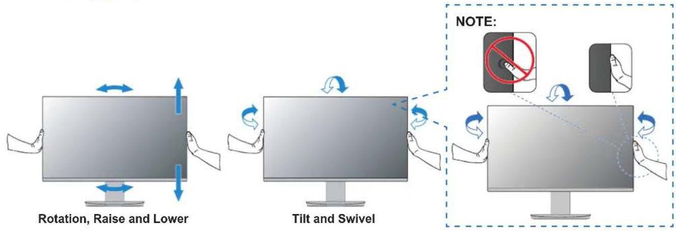
Hold the monitor on each side and adjust the screen position as desired.
For screen rotation (pivot), hold the monitor on each side, lift to its maximum height and turn it from landscape to portrait.
You can adjust the OSD (On-Screen Display) menu rotation to match the screen rotation. Refer to the [OSD ROTATION] instructions (see page 28).
■Removing the stand
TIP: Handle with care when removing the monitor stand.
1234

Parts name and Connecting Peripheral Equipment
■Front View

(1) Ambient Light Sensor Human Sensor
(2) INPUT key
(3) MENU key
(4) <> key
(5) ECO key
(6) POWER (⏻) key
(7)PowerLED
(See page 21)
■Rear View
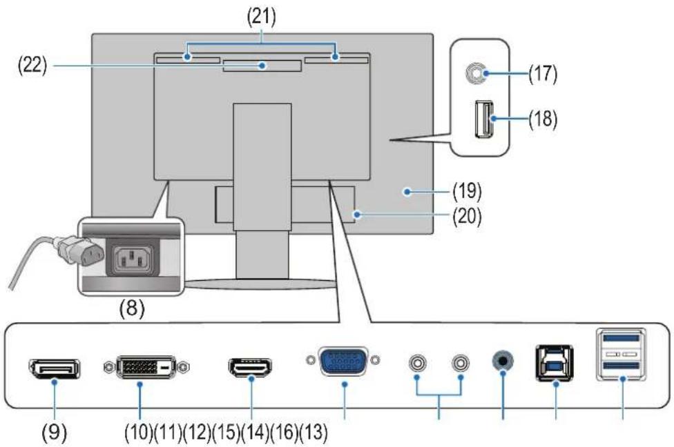
(8) AC input terminal (See page 17)
(9) DisplayPort input terminal
DisplayPort signals input (See page 16).
(10) DVI input terminal
DVI signals input (See page 16).
(11) HDMI input terminal
HDMI signals input (See page 16).
(12) VGA input terminal (mini D-Sub 15-pin)
Analog RGB signals input.
(13) ControlSync IN/OUT
Connects with the supplied ControlSync cable (See page 33).
(14) Audio input terminal
Audio signal input from external equipment such as a computer or player.
(15) USB Type-B Port
Connects with external equipment such as a computer. Please use this port to control the monitor from connected external equipment.
(16) USB Type-A Port
Connects with USB devices.
(17) Headphones input terminal
Connects with headphones.
The audio out signal is always routed to the Headphones input terminal when headphones are connected to the monitor; there is no sound from the monitor speakers.
(18) USB Type-A Port
Connects with USB devices.
(19) Security Slot (See page 44)
(20) Label
(21) Speaker
(22) Vents
Parts name and Connecting Peripheral Equipment
Connect devices to the monitor.
Turn off the power to your computer before making connections.
TIP: Place your hands on each side of the monitor to tilt the panel to a maximum tilt angle (Up 35° Down 5°) and lift up to the highest position. This provides easier access to the ports for connecting cables.

To maintain compliance with EMC regulations, use shielded cables to connect to the following terminals: HDMI IN, DisplayPort IN, Downstream Port (Type-A), USB Upstream Port (Type-B) and Audio IN. Use signal cables with ferrite core to connect to the following terminals: VGA IN and DVI IN.
NOTE: • Adjustment of the volume control to other settings than the center position may increase the ear-/headphones output voltage and therefore the sound pressure level.
- Incorrect cable connections may result in irregular operation, damage display quality/components of the LCD module and/or shorten the module's life.
• Make sure the signal cable is fully connected to the monitor and the computer.
- Check the USB flash drive for viruses as necessary.
Please adjust the screen position by referring to "Height and angle adjustment".
■Digital input
- HDMI – High-definition digital video and audio signal connection to a computer, streaming media player, Blu-ray player, game console, etc.
- DisplayPort – High-definition digital video and audio signal connection to a computer.
Depending on the computer, you may need to manually set the computer's audio to output through the DisplayPort or HDMI. Please refer to the computer's user manual.
The type of video connections that can be used to connect to a computer depends on the computer's display adapter.
For HDCP Content
HDCP is a system for preventing illegal copying of video data sent over a digital signal. If you are unable to view material via the digital inputs, this does not necessarily mean that the monitor is not functioning properly. With the implementation of HDCP, there may be cases in which certain content is protected by HDCP and might not be displayed due to the decision/intention of the HDCP community (Digital Content Protection, LLC). HDCP video content is generally commercially produced Blu-rays and DVDs, television broadcast, and streaming media services.
■Connecting to a Computer with HDMI
- Please use a HighSpeed HDMI cable with the HDMI logo.
- It may take a moment for the signal to appear after turning on the computer.
- Some display cards or drivers may not display an image correctly.
- If the monitor's power is turned on after a connected computer is turned on, sometimes an image is not displayed. In this case, please turn off the computer then turn it on again.
■Connecting to a Computer with DVI
- It may take a moment for the signal to appear after turning on the computer.
- Some display cards or drivers may not display an image correctly.
- If the monitor's power is turned on after a connected computer is turned on, sometimes an image is not displayed. In this case, please turn off the computer then turn it on again.
■Connecting to a Computer with DisplayPort
- Please use a certified DisplayPort cable.
- It may take a moment for the signal to appear after turning on the computer.
- When connecting a DisplayPort cable to a component with a signal conversion adapter, an image may not appear.
• Some DisplayPort cables feature a locking function. When removing this cable, hold down the top button to release the lock. - If the monitor's power is turned on after a connected computer is turned on, sometimes an image is not displayed. In this case, please turn off the computer then turn it on again.
Connecting the Power Cord
- Plug the power cord into the AC input terminal.
- Plug the power cord into a power outlet.

NOTE: Please make sure that enough power is supplied to the monitor. Please refer to power supply in the "Product Specifications" on page 39.
Using the cable holder
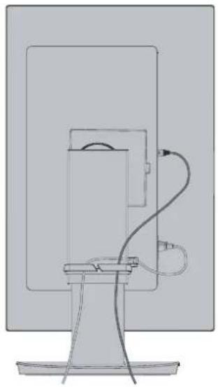
- Place the cable holder onto the stand.
- Place the cables in the cable holder firmly and evenly.

NOTE: Please check that you can still rotate, raise and lower the monitor screen after you have installed the cables.

Turning Power On/Off
Turning power on/off
- Turn on the monitor by pressing the POWER key.
NOTE: If you have any problems please refer to the Troubleshooting section of this OPERATION MANUAL (see page 35).

- Turn on the computer.
The power LED of this monitor lights up.

■Status of the monitor and patterns of the Power LED
The power management function is an energy saving feature that automatically reduces the power consumption of the monitor when the keyboard or the mouse has not been used for a fixed period.
| Power LED Status Power consumption Condition | |||
| Blue*1 | Maximum operation Approx. 47 W (EA241F)Approx. 45 W (EA271F)Approx. 42 W (EA241W) | All functions work. | |
| Blue*1 | Normal operation Approx. 15 W (EA241F)Approx. 17 W (EA271F)Approx. 15 W (EA241W) | Default setting. | |
| Amber Standby mode Approx. 0.31 W* | 2 (EA241F)Approx. 0.27 W* 2 (EA271F)Approx. 0.28 W* 2 (EA241W) | The monitor has passed a certain amount of time with no video signal input.When [USB POWER] is set to [AUTO]. | |
| Off Off mode Approx. 0.29 W* | 2 (EA241F)Approx. 0.23 W* 2 (EA271F)Approx. 0.27 W* 2 (EA241W) | Turn off the monitor by the POWER key.When [USB POWER] is set to [AUTO]. | |
*: When [LED BRIGHTNESS] (See page 27) is set to low, LED may not be lit.
*2: Power consumption depends on the setting of OSD or which devices are connected to the monitor.
TIP: This function works with computers that support VESA approved DPM (Display Power Management).
■Automatic input switching function
When connecting signal cables to the monitor, the active input is automatically switched to the newly connected input if [VIDEO DETECT] is set to [FIRST] (See page 27).
Menu Items
Displaying the menu screen

Key Function
| INPUT/SELECT When the OSD menu is closed, opens the menu for the input source. Select an input.You can directly change to the [L/B] (LOW BLUE LIGHT) mode by touching this key for 3 seconds or more when the OSD menu is closed.*1TIP: If [VIDEO DETECT] is set to [FIRST], active input is automatically switched to the newly connected input.When the OSD menu is open, enters sub-menus in the OSD menu. | |
| MENU/EXIT | Opens the OSD menu. Closes the OSD sub-menus and main menu. You can restore the saved settings in the [CUSTOMIZE SETTING] by touching this key for 3 seconds or more when the OSD menu is closed. |
| LEFT/RIGHT/UP/DOWN*2 | When the OSD menu is open, navigates through the OSD menu.When the OSD menu is closed, touch one of the following keys to open the menu for the function indicated.*1^key: [BRIGHTNESS]√key: [VOLUME] |
| ECO/RESET | When the OSD menu is open, this key sends a reset command for the OSD settings.When the OSD menu is closed, this key switches the [ECO MODE] status. You can set a mode from [OFF], [1] and [2].*1Activates the [AUTO ADJUST] function by touching this key for 3 seconds or more when the OSD menu is not open (analog input only).*1 |
| POWER (⏻) | Turns the monitor on and off. |
| Power LED Indicates that the power is on or off. | |
*: When the [HOT KEY] function is [OFF], this function is disabled.
*2: Depending on the [OSD ROTATION] setting, [LEFT], [RIGHT], [UP] and [DOWN] key guides are displayed at the < >, ∨, ∧keys differently (see page 28).
■Example of operation
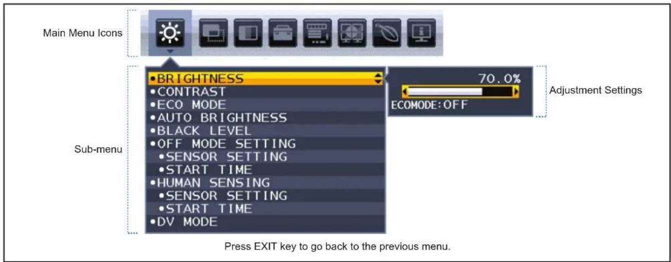
Adjusting the BRIGHTNESS menu.
- Touch MENU/EXIT key to open OSD menu.
- Touch INPUT/SELECT key to enter sub-menu.
-
Touch < or > key to adjust brightness level.
-
Touch MENU/EXIT key to go back to Sub-menu. Touch the key again to close OSD menu.
Adjusting the BRIGHTNESS is completed.
Menu item details
Below is a brief summary of where controls are under each menu item.

ECO TOOLS: Environment friendly ECO settings.

SCREEN: Screen settings.

COLOR: Color settings.

TOOLS: Volume, etc.

MENU Tools: Language, signal information, etc.

MULTI DISPLAY: Set monitor no., target monitor no., and individual adjust.

ECO INFORMATION: Displays information related to ECO.

Information: Displays monitor information such as input, resolution, etc.

ECO TOOLS
| ECO TOOLS Menu | |
| BRIGHTNESS Adjusts the overall image and background screen brightness.If [ECO MODE] is set to [1] or [2], a bar for [CARBON FOOTPRINT] will appear. | |
| CONTRAST Adjusts the overall image and background screen brightness by input signal level.TIP: This function is disabled when [L/B] is selected in the Color Control System. | |
| ECO MODE Decreases the amount of power consumption by reducing the brightness level.TIP: This function is disabled when [DV MODE] (see page 24) is set to [DYNAMIC].This function is disabled when Color Control System is set to [DICOM SIM.]. | |
| OFF Does not function. | |
| 1 Sets the brightness variable range to 70%.A [CARBON FOOTPRINT] bar will appear alongside the [BRIGHTNESS] adjustment bar. | |
| 2 Sets the brightness variable range to 30%.A [CARBON FOOTPRINT] bar will appear alongside the [BRIGHTNESS] adjustment bar. | |
| AUTO BRIGHTNESS Automatically adjusts the brightness.TIP: This function is disabled when [DV MODE] is set to [DYNAMIC].This function is disabled when Color Control System is set to [DICOM SIM.]. | |
| OFF Does not function. | |
| ON (AMBIENT LIGHT) Adjusts the brightness to the optimal setting by detecting the brightness level of the environment.* 1 | |
| BLACK LEVEL Adjusts the brightness level of black when displayed on screen. | |
| OFF MODE SETTING The Intelligent Power Manager allows the monitor to enter into power saving mode after a period of inactivity. | |
| OFF The monitor enters into power saving mode automatically when the input signal is lost. | |
| ON The monitor enters into power saving mode automatically when the amount of surrounding light goes below the level determined by you. The level can be adjusted in the [OFF MODE SENSOR SETTING].When in power saving mode, the LED on the front of the monitor becomes dark blue. When in power saving mode, touch any of the front keys, except for POWER and INPUT/SELECT keys, to return to normal mode.When the amount of surrounding light returns to normal levels, the monitor will automatically return to normal mode. | |
| SENSOR SETTING(OFF MODE SETTING) | Adjusts the threshold level for the ambient light sensor for detecting low light conditions and shows the current sensor measurement result. |
| START TIME(OFF MODE SETTING) | Adjusts the wait time to enter into a lower power consumption level when the ambient light sensor detects low light conditions. |
*† Please refer to page 32 for full "Auto Brightness" information.
| ECO TOOLS Menu | ||
| HUMAN SENSING The sensor detects the movement of a person by using the [HUMAN SENSING] function. The [HUMAN SENSING] function has three settings.TIP: Detects a person within about 1.5 m from the monitor. | ||
| OFF Does not function. | ||
| 1 (LIGHT) After it detects that there is no person during a period of time, the monitor shifts to low brightness mode automatically to reduce the power consumption. When a person comes near the monitor again, the monitor will automatically return to normal mode. [START TIME] adjusts the period of time to wait before entering low brightness mode. | ||
| 2 (DEEP) After it detects that there is no person, the monitor shifts to power saving mode automatically to reduce the power consumption. When a person comes near the monitor again, it resumes from the power saving mode. | ||
| SENSOR SETTING(HUMAN SENSING) | Adjusts the threshold level of [HUMAN SENSING].When the human icon is located on the right side of the white color bar or vermilion color wave, a person is not detected.TIP: The [HUMAN SENSING] function starts after the OSD menu is closed. | |
| START TIME(HUMAN SENSING) | Adjusts the wait time before entering to low brightness mode or power saving mode when the Human Sensor detects no person. | |
| DV MODE Dynamic Visual Mode allows you to select from the following settings:TIP: This function is disabled when Color Control System is set to [L/B], [PROGRAMMABLE] or [DICOM SIM].[STANDARD] is used for TCO Certificate compliance.When [MOVIE], [GAMING], or [PHOTO] is selected, Color Control System is set to [N(NATIVE)] automatically. | ||
| STANDARD Standard setting. | ||
| TEXT Setting that makes letters and lines crisp; best suited for basic word processing and spreadsheets. | ||
| MOVIE Setting that boosts dark tones; best suited for movies. | ||
| GAMING Setting that boosts whole tones; best suited for games that use vivid, colorful images. | ||
| PHOTO Setting that optimizes contrast; best suited for still images. | ||
| DYNAMIC | Setting that adjusts the brightness by detecting the screen's black areas and optimizes it. | |

SCREEN
| SCREEN Menu | |
| AUTO ADJUSTAnalog input only | Automatically adjusts the image position, the [H.SIZE] and [FINE] settings. |
| AUTO CONTRASTAnalog input only | Adjusts the image displayed for non-standard video inputs. |
| LEFT/RINHTAnalog input only | Controls horizontal image position within the display area of the LCD. |
| DOWN/UPAnalog input only | Controls vertical image position within the display area of the LCD. |
| H.SIZEAnalog input only | Adjusts the horizontal size by increasing or decreasing the setting.If the [AUTO ADJUST] function does not give you a satisfactory picture setting, additional tuning can be performed by using the [H.SIZE] function (dot clock). A Moiré test pattern can be used for this.This function may alter the width of the picture. Use thekey to center the image on the screen.If the [H.SIZE] is incorrectly calibrated, the result would look like the left drawing. The image should be homogeneous. → →  → →  When [H.SIZE] value is wrong.When [H.SIZE] value is improved.When [H.SIZE] value is correct. When [H.SIZE] value is wrong.When [H.SIZE] value is improved.When [H.SIZE] value is correct. |
| FINEAnalog input only | Improves focus, clarity and image stability by increasing or decreasing the setting.If the [AUTO ADJUST] and [H.SIZE] functions do not give you a satisfactory picture setting, fine tuning can be performed by using the [FINE] function.A Moiré test pattern can be used for this. If the [FINE] value is incorrectly calibrated, the result would look like the left drawing. The image should be homogeneous.   When [FINE] value is wrong.When [FINE] value is correct. When [FINE] value is wrong.When [FINE] value is correct. |
| INPUT RESOLUTIONAnalog input only | Selects one of the following pair of resolutions as the input signal priority:[1360 x 768] or [1280 x 768] or [1024 x 768] (vertical resolution 768),[1600 x 900] or [1280 x 960] (horizontal frequency 60kHz),[1680 x 1050] or [1400 x 1050] (vertical resolution 1050). |
| VIDEO LEVELHDMI input only | |
| NORMAL Setting for use with a computer. Displays all input signals of 0-255 steps. | |
| EXPAND Setting for use with audio visual equipment. Expands input signals of 16-235 steps to 0-255 steps. | |
| OVER SCANHDMI input only | Some video formats may require different scanning modes in order to best display the image. |
| ON Image size is larger than what can be displayed. The image edge will appear cropped. Approximately95 % of the image will be shown on the screen. | |
| OFF Image size stays within the display area. The whole image is displayed on the screen. | |
| EXPANSION Sets the zoom method. | |
| FULL The image is expanded to full screen regardless of the resolution.TIP: The resolution of 1280 x 768, 1360 x 768, 1280 x 720, 1600 x 900 and 1920 x 1080 are always FULL. | |
| ASPECT The image is expanded without changing the aspect ratio. | |
COLOR
| COLOR Menu | |
| Color Control System Color presets are available for adjusting color settings. | |
| 1, 2, 3, 4, 5 | Increases or decreases the [RED], [GREEN] or [BLUE] color depending upon which is selected.The change in color will appear on screen and the direction (increase or decrease) will be shown by the bars. sRGB (color preset mode [4]) dramatically improves the color fidelity in the desktop environment by a single standard RGB color space. With this color-supported environment, the operator could easily and confidently communicate color without further color management overhead in most common situations. |
| NATIVE The LCD panel's original colors that cannot be adjusted. | |
| L/B (LOW BLUE LIGHT) Reduces blue light emitted from monitor. This item cannot be adjusted.TIP: You can directly change to [L/B] (LOW BLUE LIGHT) by touching the INPUT/SELECT key for 3 seconds or more. Low Blue Light function substantially reduces blue light and helps to alleviate eye-strain. For changing to other settings from [L/B], touch the MENU/EXIT key to show OSD menu and enter Color Control System.When [L/B] is selected in Color Control System, [CONTRAST] and [DV MODE] are disabled. | |
| DICOM SIM. The white point color temperature and the gamma curve are set to a DICOM simulation. This item cannot be adjusted.NOTE: Do not use for diagnostic purposes. | |
| PROGRAMMABLE The gamma curve is adjustable through application software.* This function is not available with this monitor. | |

TOOLS
| TOOLS Menu | |
| VOLUME Controls the volume of the speakers or headphones.To mute the speaker output touch the ECO/RESET key. | |
| SOUND INPUT HDMI, DisplayPort inputs only | Selects the sound input source. |
| VIDEO DETECT Selects the method of video detection when more than one video input is connected. | |
| FIRST When the current video input signal is not present, the monitor searches for a video signal from the other video input ports. If the video signal is present in another port, the monitor switches the video source input to the detected video source automatically. The monitor will not look for other video signals while the current video source is present. | |
| NONE Video input signal detection is not enabled. | |
| RESPONSE IMPROVE Turns the [RESPONSE IMPROVE] function [ON] or [OFF]. This function may reduce blurring that occurs in some moving images. | |
| OFF TIMER The monitor will automatically power off after a period of time has passed, which you can set.Before powering off, a message will appear on the screen asking if you want to delay the turn off time by 60 minutes. Touch any OSD key to delay the power-down time. | |
| POWER SAVE TIMER Allows the monitor to turn off automatically after 2 consecutive hours in power save mode. | |
| LED BRIGHTNESS Adjusts the Power LED brightness. | |
| DDC/CI Turns the [DDC/CI] function [ON] or [OFF]. | |
| USB POWER Selects how power through the USB port is enabled in relation to the monitor's power status.TIP: Actual power consumption depends on the connected USB device even when the monitor's power is off.To avoid data loss, before changing the setting, ensure that no USB storage devices are in use by the operating system. | |
| AUTO Depending on the monitor's power condition. | |
| ON | Always working even when the monitor is in power save mode or power off. |
| FACTORY PRESET | Selecting [FACTORY PRESET] allows you to reset all OSD control settings back to the factory settings except [LANGUAGE] and [OSD LOCK OUT]. Individual settings can be reset by touching the ECO/RESET key. |

MENU TOOLS
| MENU TOOLS Menu | |||
| LANGUAGE Selects the language used by the OSD. | |||
| OSD TURN OFF The OSD menu will stay open as long as it is in use. You can select how long the monitor waits after the last key touch to close the OSD menu. The preset choices are 10-120 seconds by 5-second increments. | |||
| OSD LOCK OUT This control completely locks out access to all OSD control functions except for [BRIGHTNESS], [CONTRAST] and [VOLUME].To activate the [OSD LOCK OUT] function, open the OSD menu, select [OSD LOCK OUT], then touch INPUT/SELECT and >keys simultaneously. To deactivate, open the OSD menu then while OSD menu is open, touch INPUT/SELECT and <keys simultaneously. | |||
| OSD ROTATION This controls the OSD menu rotation.Depending on the image angle (monitor rotation), select a suitable [OSD ROTATION] setting.TIP: Please set the [KEY GUIDE] to [ON] to display the key guide. | |||
| Setting (Angle) Image Key guide | |||
| 0 |  | ||
| 90 |  | ||
| 180 |  | ||
| 270 |  | ||
| HOT KEY When this function is [ON], [BRIGHTNESS], [VOLUME] and [ECO MODE] can be changed without opening the OSD menu. | |||
| ON | |||
| BRIGHTNESS Touch the | key, then adjust the [BRIGHTNESS] level in the sub-menu that opens. | ||
| VOLUME | Touch the √key, then adjust the [VOLUME] level in the sub-menu that opens. | ||
| ECO MODE | Touch the ECO/RESET key, the [ECO MODE] sub-menu opens. You can toggle among 3 selections: [OFF], [1] and [2]. | ||
| OFF | The [HOT KEY] function for the ECO/RESET key, >key, ^key and √key are disabled. | ||
Menu Items
| MENU TOOLS Menu | |
| SIGNAL INFORMATION | |
| ON If you select [ON], the monitor displays “VIDEO INPUT” after changing the input.TIP: The compliance marks that are shown when powering on the monitor the first time are not shown when switching inputs.The compliance marks are not shown again unless the AC power cord has been disconnected at the power off status and reconnected. | |
| OFF If you select [OFF], the monitor does not display “VIDEO INPUT” after changing the input.TIP: Setting [OFF] also prevents the compliance marks from being shown when powering on the monitor. | |
| SENSOR INFORMATION | |
| ON If you select [ON], the monitor displays a “HUMAN SENSOR ON” message. | |
| OFF If you select [OFF], the monitor doesn’t display the “HUMAN SENSOR ON” message. | |
| KEY GUIDE If you select [ON], the key Guide appears on screen when the OSD menu is accessed. | |
| DATA COPY To initiate data copy from the master monitor to the sub-monitor(s), select [DATA COPY] and touch the INPUT/SELECT key. A “PROCEEDING...” indicator will appear on the screen.TIP: This function is only intended for the master monitor in ControlSync.All of the settings specified in the ControlSync chart (see page 34) will be copied from the master monitor to the sub monitor(s). | |
| CUSTOMIZE SETTING Store the current settings for easy recovery.To store current settings: Open the OSD menu, select [CUSTOMIZE SETTING], then touch the INPUT/ SELECT key. Touch the ECO/RESET key, the current settings are stored.To restore settings: Touch the MENU/EXIT key for 3 seconds or more when the OSD menu is closed. | |

MULTI DISPLAY
| MULTI DISPLAY Menu | ||
| MONITOR NO. This function is for [INDIVIDUAL ADJUST].Sets the monitor number for each monitor.Control a sub-monitor from the master monitor by [INDIVIDUAL ADJUST]:This function is for controlling a sub-monitor from the master monitor. It is useful if the sub-monitor is located at an unreachable spot.Please set the monitor number for each monitor. If you set a unique number to each of the monitors, you can control a specific monitor. If you set duplicate numbers to some of the monitors, you can control the monitors that have the same number simultaneously.TIP: A master monitor should be connected only with ControlSync OUT. Do not connect a master monitor with ControlSync IN. See ControlSync for information about master and sub-monitors (page 33). | ||
| TARGET MONITOR NO. Controls a sub-monitor's OSD by using the master monitor's control keys.Sets the sub-monitor number that is set at [MONITOR NO.]. By touching the INPUT/SELECT key, each sub-monitor displays its monitor number. | ||
| INDIVIDUAL ADJUST | ||
| ON Controls an individual sub-monitor from the master monitor.Once [ON] is set, operation at the master monitor reflects to the sub-monitor OSD.To disable [INDIVIDUAL ADJUST], please touch the INPUT and MENU keys simultaneously.TIP: Please connect monitors with the ControlSync cables. | ||

ECO INFORMATION
| ECO INFORMATION Menu | |
| CARBON SAVINGS Displays the estimated carbon savings information in kg. | |
| CARBON USAGE Displays the estimated carbon usage information in kg. This is an arithmetic estimation, not actual measurement value. | |
| COST SAVINGS Displays the electricity cost savings in balance. | |
| CARBON CONVERT SETTING | Adjusts the carbon footprint factor in the carbon saving calculation. This initial setting is based on the OECD data (2008 Edition). |
| CURRENCY SETTING Displays electricity pricing in 6 currency units. | |
| CURRENCY CONVERT SETTING | Displays electricity savings in kW/hour (US Currency is default).TIP: The initial setting is US Dollar [] in [CURRENCY SETTING] and [0.11] in [CURRENCY CONVERT SETTING].This setting can be changed by using the [ECO INFORMATION] menu.If you want to use the French setting, please refer to the steps below:1. Touch the MENU/EXIT key and select the [ECO INFORMATION] menu using thekey.2. Select the [CURRENCY SETTING] item by touching the^orkey.3. The French currency unit is Euro [€]*. You can adjust currency setting to Euro icon [€] from US Dollar [$] by touching the<orkey in [CURRENCY SETTING] item.4. Select [CURRENCY CONVERT SETTING] by touching the^orkey.5. Adjust [CURRENCY CONVERT SETTING] by touching the<orkey.* This initial Euro [€] setting is based on the OECD data for Germany (2007 Edition).Please check the receipt of electricity prices for France or OECD data for France.The French value according to the OECD data (2007 Edition) was €0.12. € |

INFORMATION
| INFORMATION Menu | |
| INFORMATION Provides information about the current input signal, the model, serial numbers of your monitor. |
■OSD Warning
OSD warning messages close by touching the MENU/EXIT key.
NO SIGNAL: This function gives a warning when there is no horizontal or vertical sync. After power is turned on or when there is a change of input signal, the “NO SIGNAL” window will appear.
OUT OF RANGE: This function gives a recommendation of the optimized resolution and refresh rate. After the power is turned on, or there is a change of input signal, or if the video signal doesn't have proper timing, the "OUT OF RANGE" message will appear.
Using the HUMAN SENSING function
The Human Sensing function reduces power consumption by detecting the movement of a person.
The [HUMAN SENSING] has following two settings:
| MODE HUMAN SENSING SETTING No person in front of the monitor | |
| LIGHT 1 BRIGHTNESS 0 % | |
| DEEP 2 Power saving mode | |
Image of human sensing operation
A. When the sensor detects no person in front of the monitor, the monitor stays on for the period of time which is set at [HUMAN SENSING] → [START TIME] (see page 24).
B. The monitor displays a notification on the screen after the period of time with no human detected has passed. You can set the notification screen at [SENSOR INFORMATION] (see page 29).

C. After displaying the notification, if [LIGHT] is set at [HUMAN SENSING], the monitor screen gets gradually darker until it gets to 0 % brightness.
If [DEEP] is set at [HUMAN SENSING], the monitor enters into power saving mode.
D. When the sensor detects a person coming back, the monitor is automatically returned from power saving mode to normal mode.
TIP: When [LIGHT] is set at [HUMAN SENSING], the monitor screen gets gradually brighter as it returns to the original brightness.
E. The monitor returns to normal mode.
![graph LR A["A user leaves"] --> B["Normal mode Normal mode + notification"] B --> C["HUMAN SENSING ON ENTER INTO POWER SAVE MODE SHORTLY REDUCE POWER 27%"] C --> D["Power save mode [HUMAN SENSING"] (LIGHT/DEEP)] D --> E["Back to Normal mode"] E --> F["A user is back"]](/content/2026/08/1614798/images/9e422cc9a03ac0088671bc65c2b96fd6c8272103f96048cf4ebebfed56c9a14a.jpg)
Using the AUTO BRIGHTNESS function
The brightness of the LCD screen can be set to increase or decrease depending on the amount of ambient lighting within the room. If the room is bright, the monitor becomes correspondingly bright. If the room is dim, then the monitor will dim accordingly. The purpose of this function is to make the viewing experience more comfortable to the eye in a variety of lighting conditions.
SETUP
Use the following procedures to select the brightness range the monitor will use when the [AUTO BRIGHTNESS] function is activated.
- Set a level for the bright room condition.
This is the maximum brightness level the monitor will rise to when the ambient lighting level is highest. Configure this setting when the room is at its brightest.
Select [ON] in the [AUTO BRIGHTNESS] menu (Figure 1). Then use the front Keys to move the cursor up to the [BRIGHTNESS] setting. Choose the desired brightness level (Figure 2).


Figure 1 Figure 2
- Set a level for the dark room condition.
This is the minimum brightness level the monitor will lower to when the ambient lighting level is low. Make sure the room is at its darkest when setting this level. Then use the front Keys to move the cursor up to the [BRIGHTNESS] setting. Choose the desired brightness level (Figure 3).

Figure 3
When the [AUTO BRIGHTNESS] function is enabled the Brightness level of the screen changes automatically according to the lighting conditions of the room (Figure 4).

Figure 4
Using the ControlSync function
ControlSync simultaneously controls all sub monitors connected to a master monitor. It can also individually control a single sub-monitor using the [INDIVIDUAL ADJUST] function. Please refer to the figure below.
![graph TD A["Master Monitor"] -->|IN (Gray)| B["In"] B --> C["ControlSync cable"] C --> D["(Gray)(Black) (Gray)(Black)"] D --> E["Sub Monitor 1 Sub Monitor 2"] E --> F["OUT (Black)"] F --> G["IN OUT"] G --> H["IN OUT"] H --> I["Up to five sub-monitors"] I --> J["Next monitor"]](/content/2026/08/1614798/images/eb81022696517bc13f50a238541bd930cf4abfa5689f07e43c41461563d2eed6.jpg)
TIP: The ControlSync icon will appear on the upper left of the OSD menu in the sub-monitors. Do not connect the ControlSync ports IN-to-IN or OUT-to-OUT. The monitors' ControlSync ports must be connected OUT-to-IN. Do not make a "loop" connection by connecting the last monitor in the chain back to the master monitor.

Turn off the power and disconnect the power cables for all monitors. Connect the
ControlSync cables, then connect the power cables, and then turn on the power for each monitor.
■Controlling all connected sub-monitors (Synchronized control):
- Connect a ControlSync cable (ø 2.5) to the master monitor's ControlSync OUT port and into a sub monitor's ControlSync IN port. Up to five monitors can be daisy-chained together by connecting the monitors to each other via the ControlSync OUT to IN ports on the monitors.
- Follow the steps for [DATA COPY] (see page 29). When a setting for the master monitor is adjusted, it will be copied and sent to the connected sub-monitor(s) automatically.
■Controlling a target monitor (Individual Adjust):
- Touch the MENU key to open the OSD menu on the master monitor.
- Touch the > key to enter the [MULTI DISPLAY] control. When the cursor is on [TARGET MONITOR NO.], a sub-monitor number menu opens. Use the < or > key to select the sub-monitor number. If you touch the INPUT/SELECT key, each sub-monitor displays its monitor number.

- Touch the √ or ∧ key to select [INDIVIDUAL ADJUST] and then set it to [ON].
Control the sub-monitor's OSD using the master monitor's control keys.
TIP: To disable [INDIVIDUAL ADJUST], touch the INPUT and MENU keys simultaneously.
The following settings can be controlled by ControlSync:
| Synchronized control Individual adjust | |||
| ECO TOOLS BRIGHTNESS* | Yes Yes | ||
| CONTRAST No Yes | |||
| ECO MODE Yes Yes | |||
| AUTO BRIGHTNESS Yes Yes | |||
| BLACK LEVEL No Yes | |||
| OFF MODE SETTING Yes Yes | |||
| SENSOR SETTING (OFF MODE SETTING) Yes Yes | |||
| START TIME (OFF MODE SETTING) Yes Yes | |||
| HUMAN SENSING Yes Yes | |||
| SENSOR SETTING (HUMAN SENSING) | Yes Yes | ||
| START TIME (HUMAN SENSING) | Yes Yes | ||
| DV MODE | Yes Yes | ||
| SCREEN | AUTO ADJUST | No Yes | |
| AUTO CONTRAST | No Yes | ||
| LEFT/RIGHT | No Yes | ||
| DOWN/UP | No Yes | ||
| H.SIZE | No Yes | ||
| FINE | No Yes | ||
| INPUT RESOLUTION | No Yes | ||
| VIDEO LEVEL | No Yes | ||
| OVER SCAN | No Yes | ||
| EXPANSION | Yes Yes | ||
| COLOR | Color Control System | Yes | Yes |
| R, G, B, color gain | No Yes | ||
| TOOLS | VOLUME | Yes | Yes |
| SOUND INPUT | No Yes | ||
| VIDEO DETECT | No Yes | ||
| RESPONSE IMPROVE | No Yes | ||
| OFF TIMER | Yes Yes | ||
| POWER SAVE TIMER No Yes | |||
| LED BRIGHTNESS | Yes Yes | ||
| DDC/CI | Yes Yes | ||
| USB POWER | No Yes | ||
| FACTORY PRESET | No Yes | ||
| MENU TOOLS | LANGUAGE | Yes Yes | |
| OSD TURN OFF | Yes Yes | ||
| OSD LOCK OUT | Yes Yes | ||
| OSD ROTATION | No Yes | ||
| HOT KEY | Yes Yes | ||
| SIGNAL INFORMATION | Yes Yes | ||
| SENSOR INFORMATION | Yes Yes | ||
| KEY GUIDE | Yes Yes | ||
| DATA COPY | No | No | |
| CUSTOMIZE SETTING | No Yes | ||
| MULTI DISPLAY | MONITOR NO. | No | No |
| TARGET MONITOR NO. | No | No | |
| INDIVIDUAL ADJUST | No | No | |
| ECO INFORMATION | CARBON SAVINGS | No | No |
| CARBON USAGE | No | No | |
| COST SAVINGS | No | No | |
| CARBON CONVERT SETTING | Yes Yes | ||
| CURRENCY SETTING | Yes Yes | ||
| CURRENCY CONVERT SETTING | Yes Yes | ||
Other settings:
Power Control (DC switch)
Ambient Light Sensor
Human Sensor Result
Audio Mute
TIP: Only the master monitor's human sensor and ambient light sensor are active. Please do not cover these sensors (see page 13).
After connecting all power cords and ControlSync cables, check that ControlSync operates correctly by turning the master monitor's power off then back on.
Do not use the ControlSync connectors for any purpose other than specified.
* This value is not a directly adjusted output value. This is adjusted relatively.
Troubleshooting
■Screen Image and Video Signal Issues
No picture
- Make sure the signal cable is fully connected to the monitor and the computer.
- Make sure the computer's display card is fully seated in its slot.
- Make sure there is no DisplayPort converter adapter connected. The monitor does not support DisplayPort converter adapter.
- Make sure both the computer and monitor are powered on.
- The monitor may be in power saving mode. The monitor automatically goes into standby at the preset time period after the video signal is lost.
- If the current input terminal connection has no active input signal, touch the INPUT/SELECT key to switch inputs.
- If the OSD menu setting [VIDEO DETECT] is set to [NONE], change the setting to [FIRST].
- Make sure that a supported resolution has been selected on the display card or system being used. If in doubt, please refer to the OPERATION MANUAL of the display controller or system to change the resolution.
- Check the monitor and your display card with respect to compatibility and recommended signal timings.
- Check the signal cable connector for bent or pushed-in pins.
- Make sure the connected device outputs a signal to the monitor.
- If the front LED is dark blue, check the status of the [OFF MODE SETTING] (see page 23) or [HUMAN SENSING] (see page 24).
- The monitor will automatically turn off by the "POWER SAVE TIMER" function when the "POWER SAVE TIMER" setting is "ON" and continues in power save mode for 2 hours. Please touch the power key.
Image Persistence
- Do not display a still picture for a long period, as this could cause a residual image (see page 10).
Selected resolution is not displayed properly
- If the resolution you set is over or under a range, "OUT OF RANGE" window will appear then warn you. Please set supported resolution at the connected computer.
The image is unstable, unfocused or swimming is apparent
- Use the OSD Image Adjust controls to focus and adjust the display by increasing or decreasing the [Fine] adjustment. When the display mode is changed, the OSD Image Adjustsettings may need to be resadjusted.
- Make sure the signal cable is fully connected to the monitor and the computer.
- Check the monitor and your display card with respect to compatibility and recommended signal timings.
- If your text is garbled, change the video mode to non-interlace and use the 60Hz refresh rate.
- Disconnect the DisplayPort cable and touch the MENU key. Select DP LONG CABLE then adjust the OSD value using the "(LEFT)" key or "(RIGHT)" key.
Picture is not bright
- If the brightness fluctuates, make sure [DV MODE] is set to [STANDARD].
- Make sure [ECO MODE] and [AUTO BRIGHTNESS] are turned off.
- If the brightness fluctuates, make sure [AUTO BRIGHTNESS] is turned off.
- Make sure the signal cable is fully connected to the monitor and the computer.
- LCD brightness degradation occurs due to long-term usage or extreme cold conditions.
- When using an HDMI input terminal, please change [VIDEO LEVEL] (see page 25).
Display image is not sized properly
- Use the OSD Image Adjust controls to increase or decrease the Coarse adjustment.
- Make sure that a Major Supported Timings has been selected for the display card in the system being used. (Please consult the manual for the system or display card for supported resolution and changing the settings.)
- When using an HDMI input terminal, please change [OVER SCAN] (see page 25).
Brightness variations over time
- Change [AUTO BRIGHTNESS] to [OFF] and then adjust the [BRIGHTNESS].
- Change [DV MODE] to [STANDARD] and then adjust the [BRIGHTNESS].
TIP: When [AUTO BRIGHTNESS] is set to [ON], the monitor automatically adjusts brightness based on the environment. When the brightness of surrounding environment changes, the monitor will also change. When [DV MODE] is set to [DYNAMIC], the monitor automatically adjusts brightness based on the video signal.
Displayed OSD menu is rotated
- Make sure of the [OSD ROTATION] setting.
■Hardware Issues
POWER Key does not respond
- Unplug the power cord of the monitor from the AC outlet to turn off and reset the monitor.
LED on monitor is not lit (no blue or amber color can be seen)
- Make sure the power cord is properly connected to the monitor and the wall, and make sure the monitor's power switch is on.
- Increase the [LED BRIGHTNESS] adjustment.
No Video
- If no video is present on the screen, turn the POWER key off and on again.
• Make sure the computer is not in a power-saving mode by touching the connected keyboard or the connected mouse. - When using DisplayPort, some display cards do not output video signal under low resolution modes when the monitor is turned OFF/ON or disconnected/connected from the AC power cord.
- When using an HDMI input terminal, please change [OVER SCAN] (see page 25).
• Make sure [VIDEO DETECT] is set to [NONE] (see page 27).
No Sound
- Check to see if [MUTE] is activated.
- Check to see if [VOLUME] is set to a minimum.
- Check to see if the computer supports an audio signal through DisplayPort or HDMI.
- Connect headphones to the monitor.
The USB Hub does not operate
- Check to make sure that the USB cable is properly connected. Refer to your USB device OPERATION MANUAL.
- Check that the USB upstream port on the monitor is connected to the USB downstream port on the computer, and make sure the computer is ON.
- Turn the power switch off and on again.
Human sensor does not work
- Make sure there is no object in front of the Human sensor.
- Make sure there is no equipment that radiates infrared rays in front of the monitor.
ControlSync does not work
- Make sure the ControlSync cable is connected correctly.
- Make sure the ControlSync cable is not in "loop" connection.
- Master monitor should be connected with ControlSync OUT connector only.
- Please use the provided ControlSync cables.
- You can use up to five sub monitors via ControlSync.
Specifications
■Compatible signal timing
The following table shows the typical factory preset signal timing for each connection type. Some display cards may not be able to support the required resolution for proper image reproduction with the selected connection. The monitor will show the proper image by automatically adjusting the factory preset timing signal.
EA241F, EA271F
| Resolution | Vertical Frequency | Notes | |
| H | V | ||
| 640 x 480 60/72/75 Hz | |||
| 720 x 400 70 Hz | |||
| 720 x 480 60 Hz | |||
| 720 x 576 50 Hz | |||
| 800 x 600 56/60/72/75 Hz SVGA | |||
| 1024 x 768 60/70/75 Hz XGA | |||
| 1280 x 720 50/60 Hz 720p | |||
| 1280 x 960 60/75 Hz | |||
| 1280 x 1024 60/75 Hz SXGA | |||
| 1440 x 900 60 Hz | |||
| 1600 x 1200 60 Hz | |||
| 1920 x 1080 50/60 Hz 1080p, Recommended (60 Hz) | |||
Interlace signal is not supported.
EA241W
| Resolution | Vertical Frequency | Notes | |
| H | V | ||
| 640 x 480 60 Hz | |||
| 720 x 480 60 Hz | |||
| 720 x 576 50 Hz | |||
| 800 x 600 56/60 Hz SVGA | |||
| 1024 x 768 60 Hz XGA | |||
| 1280 x 720 50/60 Hz 720p | |||
| 1280 x 960 60 Hz | |||
| 1280 x 1024 60 Hz SXGA | |||
| 1440 x 900 60 Hz | |||
| 1600 x 1200 60 Hz UXGA | |||
| 1680 x 1050 60 Hz | |||
| 1920 x 1080 50/60 Hz 1080p | |||
| 1920 x 1200 60 Hz Recommended | |||
Interlace signal is not supported.
TIP: When the selected monitor resolution is not a native panel resolution, the text contents appearance in the monitor screen is expanded in a horizontal or vertical direction to show the non-native resolution to full screen. This expansion is done by interpolated resolution technologies, which are normal and widely used in flat panel devices.
■Product Specifications
| Model EA241F EA271F | |||
| Product LCD MONITOR | |||
| LCD component 23.8 class (Diagonal 60) | .47 cm / 23-13/16 inch)Active matrix: thin film transistor (TFT) liquid crystal display (LCD) | 27 class (Diagonal 68.60 cm / 27 inch)Active matrix: thin film transistor (TFT) liquid crystal display (LCD) | |
| Max. resolution (pixels) 1920 x 1080 | |||
| Max. colors Approx. 16.7 million colors | |||
| Pixel pitch 0.275 mm (H) x 0.275 mm (V) | 0.311 mm (H) x 0.311 mm (V) | ||
| Brightness (typical)*1 | 250 cd/m2 | ||
| Contrast ratio (typical)*1 | 1000:1 (5000:1, DV MODE [DYNAMIC]) | ||
| Viewing angle 178° right/left, 178° up/down (contrast ratio ≥ 10) | |||
| Response Time (typical) 14 ms (Gray to Gray) | Gray) RESPONSE IMPROVE [OFF]5 ms (Gray to Gray) RESPONSE IMPROVE [ON] | 14 ms (Gray to Gray) RESPONSE IMPROVE [OFF]6 ms (Gray to Gray) RESPONSE IMPROVE [ON] | |
| Screen active area 527.0 mm (W) x 296 | 46 mm (H)20-3/4 inch (W) x 11-11/16 inch (H) | 597.9 mm (W) x 336.3 mm (H)23-9/16 inch (W) x 13-1/4 inch (H) | |
| Ratio of effective pixel*3 | ≥ 99.9997% ≥ 99.9997% | ||
| Input terminals HDMI HDMI x 1 (HDCP 1.4) | |||
TIP: Technical specifications are subject to change without notice.
*1: Brightness and contrast ratio will depend on input mode and other picture settings. Brightness level will decrease over time. Due to the nature of the equipment, it is not possible to precisely maintain a constant level of brightness.
2 : Excluding protrusions.
*3. Even though the LCD panel of this product is manufactured with high precision, there may be ineffective pixels such as ones which never lights up or always lighting up. "Ratio of effective pixel" means the ratio of the number of effective pixel (subtracting the number of ineffective pixels from the whole number of pixels) against the whole number of pixels on the LCD panel. Please note that presence of ineffective pixels does not mean failure of LCD panel.
* : Including when the monitor is installed on a flexible arm.
*5. Factory setting.
*5. When no signal inputs. Time for power management function: Less than 1 min.
■Product Specifications
| Model EA241W | ||
| Product LCD MONITOR | ||
| LCD component 24.1 class (Diagonal 61 | 13 cm / 24-1/16 inch)Active matrix: thin film transistor (TFT) liquid crystal display (LCD) | |
| Max. resolution (pixels) 1920 x 1200 | ||
| Max. colors Approx. 16.7 million colors | ||
| Pixel pitch 0.270 mm (H) x 0.270 mm (V) | ||
| Brightness (typical)*1 | 300 cd/m2 | |
| Contrast ratio (typical)*1 | 1000:1 (5000:1, DV MODE [DYNAMIC]) | |
| Viewing angle 178° right/left, 178° up/down (contrast ratio ≥ 10) | ||
| Response Time (typical) 14 ms (Gray to Gray) RESPONSE IMPROVE [OFF]6 ms (Gray to Gray) RESPONSE IMPROVE [ON] | ||
| Screen active area 518.4 mm (W) x 324 | 0 mm (H)20-7/16 inch (W) x 12-3/4 inch (H) | |
| Ratio of effective pixel*3 | ≥ 99.9997% | |
| Input terminals HDMI HDMI x 1 (HDCP 1.4) | ||
TIP: Technical specifications are subject to change without notice.
*1: Brightness and contrast ratio will depend on input mode and other picture settings. Brightness level will decrease over time. Due to the nature of the equipment, it is not possible to precisely maintain a constant level of brightness.
2 : Excluding protrusions.
*3 Even though the LCD panel of this product is manufactured with high precision, there may be ineffective pixels such as ones which never lights up or always lighting up. "Ratio of effective pixel" means the ratio of the number of effective pixel (subtracting the number of ineffective pixels from the whole number of pixels) against the whole number of pixels on the LCD panel. Please note that presence of ineffective pixels does not mean failure of LCD panel.
: Including when the monitor is installed on a flexible arm.
*5. Factory setting.
*5. When no signal inputs. Time for power management function: Less than 1 min.
■Dimensional Drawings
Note that the values shown are approximate values.
[EA241F] (Unit: mm)

(Unit: mm)
■Dimensional Drawings
Note that the values shown are approximate values.
[EA241W] (Unit: mm)

Mounting Precautions
- When moving the monitor, be sure to hold its sides or bottom. Do not hold the LCD panel or buttons. This may cause product damage, failure, or injury.
• To attach a VESA-compliant mounting bracket, use M4 screws that are 6 mm to 10 mm longer than the thickness of the mounting bracket.

- Be sure to use a wall-mount bracket designed or designated for mounting the monitor.
- This monitor and bracket must be installed on a wall which can endure at least 4 times or more the weight of the monitor. Install by the most suitable method for the material and the structure.
- Do not use an impact driver.
- Do not use any screw holes other than those for mounting brackets, located on the rear of the monitor, for installation.

Screw holes for mounting brackets
- When installing, check the tilt angle in the Product Specifications (page 39).

• After mounting, please carefully ensure the monitor is secure, and not able to come loose from the wall or mount.
■Installing a security cable and prevent tipping
As a security measure, you can secure the monitor to a fixed object with an optional security cable.
Please follow the security cable supplier's recommended instructions to install.
A security cable (purchased separately) is designed as a deterrent, it is not guaranteed to prevent the device from being mishandled or stolen.
When using the monitor, fasten the monitor to a wall using a cord that can support the weight of the monitor in order to prevent the monitor from falling. Installing must be done by a qualified technician, and please contact your supplier for more information.

Manufacturer's Recycling and Energy Information
We are strongly committed to environmental protection and sees recycling as one of the company's top priorities in trying to minimize the burden placed on the environment. We are engaged in developing environmentally friendly products, and always strive to help define and comply with the latest independent standards from agencies such as ISO (International Organization for Standardization) and TCO (Swedish Trades Union).
Energy Saving
This monitor features an advanced energy saving capability. When a Display Power Management signal is sent to the monitor, the Energy Saving mode is activated. The monitor enters a single Energy Saving mode.
For additional information visit:
https://www.sharpusa.com/ (in USA)
https://www.sharpnecdisplays.eu (in Europe)
https://www.sharp-nec-displays.com/global/index.html (Global)
Addition explanation to EcoDesign Regulation
The following setting conforms to the “Normal Configuration” as defined in the “EcoDesign Regulation (2019/2021)” and is the recommended setting.
• [DV MODE] is set to [DYNAMIC]
If you change this setting the power consumption can be higher than using the recommended setting.
Due to the various possibilities to save energy, the different power modes named as “standby mode”. The monitor enter into “standby mode” if you use the recommended setting.
SHARP
SHARP CORPORATION
- TABLE OF CONTENTS
- DEAR CUSTOMER
- IMPORTANT INFORMATION
- SUPPLIED COMPONENTS
- INSTALLATION
- PARTS NAME AND CONNECTING PERIPHERAL EQUIPMENT
- CONNECTING THE POWER CORD
- USING THE CABLE HOLDER
- TURNING POWER ON/OFF
- MENU ITEMS
- USING THE HUMAN SENSING FUNCTION
- USING THE AUTO BRIGHTNESS FUNCTION
- USING THE CONTROLSYNC FUNCTION
- TROUBLESHOOTING
- SPECIFICATIONS
- MOUNTING PRECAUTIONS
- MANUFACTURER'S RECYCLING AND ENERGY INFORMATION
- NOTE
- WARNING
- (FOR CUSTOMERS IN U.K.)
- IMPORTANT
- INFORMATION ON THE DISPOSAL OF THIS EQUIPMENT
- TCO CERTIFIED
- TCO CERTIFIED — A THIRD-PARTY SUSTAINABILITY CERTIFICATION FOR IT PRODUCTS
- FOR OPTIMUM PERFORMANCE, PLEASE NOTE
- THE FOLLOWING WHEN SETTING UP AND
- USING THE LCD COLOR MONITOR
- ABOUT THE SYMBOLS
- CAUTION
- IMAGE PERSISTENCE
- RECOMMENDED USE & MAINTENANCE
- RECOMMENDED USE
- ERGONOMICS
- CORRECT PLACEMENT AND ADJUSTMENT OF THE MONITOR CAN REDUCE EYE, SHOULDER, AND NECK FATIGUE. CHECK THE FOLLOWING WHEN YOU POSITION THE MONITOR
- MAINTENANCE
- CLEANING THE LCD SCREEN
- CLEANING THE CABINET
- TRADEMARK AND SOFTWARE LICENSE
- TRADEMARKS
- ATTACHING THE BASE
- HEIGHT AND ANGLE ADJUSTMENT
- REMOVING THE STAND
- REAR VIEW
- CONNECT DEVICES TO THE MONITOR
- DIGITAL INPUT
- FOR HDCP CONTENT
- CONNECTING TO A COMPUTER WITH HDMI
- CONNECTING TO A COMPUTER WITH DVI
- CONNECTING TO A COMPUTER WITH DISPLAYPORT
- STATUS OF THE MONITOR AND PATTERNS OF THE POWER LED
- AUTOMATIC INPUT SWITCHING FUNCTION
- EXAMPLE OF OPERATION
- MENU ITEM DETAILS
- ECO TOOLS
- SCREEN
- COLOR
- TOOLS
- MENU TOOLS
- MULTI DISPLAY
- ECO INFORMATION
- INFORMATION
- OSD WARNING
- IMAGE OF HUMAN SENSING OPERATION
- SETUP
- CONTROLLING ALL CONNECTED SUB-MONITORS (SYNCHRONIZED CONTROL)
- CONTROLLING A TARGET MONITOR (INDIVIDUAL ADJUST)
- SCREEN IMAGE AND VIDEO SIGNAL ISSUES
- NO PICTURE
- SELECTED RESOLUTION IS NOT DISPLAYED PROPERLY
- THE IMAGE IS UNSTABLE, UNFOCUSED OR SWIMMING IS APPARENT
- PICTURE IS NOT BRIGHT
- DISPLAY IMAGE IS NOT SIZED PROPERLY
- BRIGHTNESS VARIATIONS OVER TIME
- DISPLAYED OSD MENU IS ROTATED
- HARDWARE ISSUES
- POWER KEY DOES NOT RESPOND
- LED ON MONITOR IS NOT LIT (NO BLUE OR AMBER COLOR CAN BE SEEN)
- NO VIDEO
- NO SOUND
- THE USB HUB DOES NOT OPERATE
- HUMAN SENSOR DOES NOT WORK
- CONTROLSYNC DOES NOT WORK
- COMPATIBLE SIGNAL TIMING
- DIMENSIONAL DRAWINGS
- INSTALLING A SECURITY CABLE AND PREVENT TIPPING
- ENERGY SAVING
- ADDITION EXPLANATION TO ECODESIGN REGULATION
- SHARP
- SHARP CORPORATION
Brand : SHARP
Model : MultiSync EA241W
Category : Monitor