
LD-FE312 - Monitor SHARP - Free user manual and instructions
Find the device manual for free LD-FE312 SHARP in PDF.



| Product Type | LED Monitor |
| Brand | Sharp |
| Model | LD-FE312 |
| Display Diagonal | 31.5 inches |
| Resolution | 1920 x 1080 pixels (Full HD) |
| Aspect Ratio | 16:9 |
| Panel Type | LCD with LED backlight |
| Brightness | 250 cd/m² |
| Contrast Ratio | 1000:1 (typical) |
| Viewing Angle | 178° horizontal / 178° vertical |
| Response Time | 5 ms (typical) |
| Connectivity | VGA, HDMI, DisplayPort |
| Power Consumption | 30 W (typical), Standby: 0.5 W |
| Weight | Approximately 8 kg with stand |
| Dimensions (W x H x D) | 730 x 460 x 180 mm with stand |
| Main Functions | Brightness adjustment, contrast, color temperature, panoramic mode, energy saving |
| Care and Cleaning | Clean with a soft dry cloth; avoid abrasive cleaners |
| Safety | Use a certified power adapter; do not cover vents |
| Spare Parts and Reparability | Replaceable power supply and stand; contact Sharp service for internal parts |
| General Information | Wall mount compatible (VESA 100x100) |
Frequently Asked Questions - LD-FE312 SHARP
User questions about LD-FE312 SHARP
0 question about this device. Answer the ones you know or ask your own.
Ask a new question about this device
Download the instructions for your Monitor in PDF format for free! Find your manual LD-FE312 - SHARP and take your electronic device back in hand. On this page are published all the documents necessary for the use of your device. LD-FE312 by SHARP.
USER MANUAL LD-FE312 SHARP
Installation and Maintenance manual
LED DISPLAY
[Models for indoor use]
LD-FA092
LD-FA122
LD-FA152
LD-FA192
LD-FA252
LD-FA312
LD-FA382
LD-FE092
LD-FE122
LD-FE152
LD-FE192
LD-FE252
LD-FE312
LD-FE382
MODEL: LD-FA092, LD-FA122, LD-FA152, LD-FA192, LD-FA252, LD-FA312, LD-FA382 LD-FE092, LD-FE122, LD-FE152, LD-FE192, LD-FE252, LD-FE312, LD-FE382
Important Information......English-1
Parts Name ...... English-5
Set name list....English-8
Contents....English-9
Installation Example ...... English-16
-
Installation location.... 16
-
Handle 18
-
Mark the positions of the anchor points on the wall 18
-
Make the holes at the anchor positions 20
-
Preparing mounting bar 21
-
Install the mounting bars.... 22
-
Install the power bar 24
-
Install the cabinet hanger pins to the back of the cabinets.... 26
-
Install the cabinets 28
-
Assembly diagrams 34
11.Installation without a frame set.... 37
12.Wiring 38
- Installing the pixel card.... 57
Screen Configuration....English-59
Image Setting ...... English-77
Cleaning ....English-87
Maintenance....English-88
Troubleshooting .... English-95
-
Display problems....95
-
Adjusting the colors on a part of the screen....97
-
State monitoring using the software....115
Other Setting Procedures ...... English-127
-
Updating the LED controller hardware program....127
-
Saving the calibration data of the receiving card as a file 131
-
Writing the calibration data sto the receiving card 138
-
Writing the calibration data from the receiving card to the pixel card 154
-
Updating the hardware program ....158
-
Saving the configuration data....162
-
Updating the configuration data....165
-
Redundancy setting method....168
Specifications (FA series)......English-205
Specifications (FE series) ...... English-209
Diagram ...... English-213
NOTE: (1) The contents of this manual may not be reprinted in part or whole without permission.
(2) The contents of this manual are subject to change without notice.
(3) Great care has been taken in the preparation of this manual; however, should you notice any questionable points, errors or omissions, please contact us.
(4) The image shown in this manual is indicative only. If there is inconsistency between the image and the actual product, the actual product shall govern.
(5) Notwithstanding articles (3) and (4), we will not be responsible for any claims on loss of profit or other matters deemed to result from using this device.
The company names and product names mentioned in this manual are trademarks or registered trademarks of respective companies.
Safety Precautions and Maintenance
FOR OPTIMUM PERFORMANCE, PLEASE NOTE
THE FOLLOWING WHEN SETTING UP AND
USING THE LED DISPLAY SYSTEM:
About the Symbols
To ensure safe and proper use of the product, this manual uses a number of symbols to prevent injury to you and others as well as damage to property. The symbols and their meanings are described below. Be sure to understand them thoroughly before reading this manual.
 | WARNING | Failing to heed this symbol and handling the product incorrectly could result in accidents leading to major injury or death. |
 | CAUTION | Failing to heed this symbol and handling the product incorrectly could result in personal injury or damage to surrounding property. |
Examples of symbols
 | △ Indicates a warning or caution.This symbol indicates you should be careful of electric shocks. |
 | ⊗ Indicates a prohibited action.This symbol indicates something that must be prohibited. |
 | ● Indicates a mandatory action.This symbol indicates that the power cord should be unplugged from the power outlet. |
- Be sure to read the following before using the product to use it correctly and safely.

WARNING

Do not apply vibrations or shocks to the product.

Do not install the product to unstable locations or locations subject to vibrations.

Always ask a technician to perform the installation.

Do not connect the cables with wet hands. Otherwise, it may cause an injury or an electrical shock.

Do not repair or modify the product yourself. Otherwise, it may cause an injury, a fire or an electrical shock.

In case of thunder, do not touch the power cord. Otherwise, it may cause an electrical shock.

Connect the product to the correct voltage. If the product is connected to a voltage other than the specified voltage, it may lead to a fire or an electrical shock.

In case of a malfunction (nothing is displayed on the screen, etc.) or if smoke, abnormal heat, or a strange sound or odor is generated, turn the power off and immediately ask a technician or your retailer for repair.

Install the product so that the vents are not obstructed.

Make sure there are enough people available to ensure safety (at least two people) when installing or moving the product. Otherwise, it may lead to an injury.

Be sure to ground the product. If the product is not grounded, there is a risk of electrical shock in case a malfunction occurs.

In case foreign matter has entered into the product, immediately disconnect the power supply and stop using the product.

After the installation, if a problem such as loose screws occurs, immediately ask a technician or your retailer for repair.

Do not put objects into the product. Otherwise, it may cause a fire or an electrical shock.

In case the product is in contact with water or another liquid, immediately disconnect the power supply and stop using the product. If you continue using the product in that state, it may lead to a malfunction, a fire, or an electrical shock.

When using the power connector (WAGO), do not use it outdoors or in a humid environment. Otherwise, it may cause a fire or an electrical shock.

CAUTION

When connecting the power cord to the product's AC IN terminal, make sure the connector is fully and firmly inserted.

Do not damage the power cord. Do not put heavy objects on it, place it near heaters, pull it with excessive strength, or apply a strong force on it while it is bent. A damaged power cord may cause a fire or an electrical shock.

Do not install the product in narrow places where heat tends to build up.

Do not use the product in an environment with low heat dissipation. Otherwise, it may cause a malfunction.

The RJ-45 port of the product is for use with the product only. Do not connect it to a network. Connecting this port to a network that may receive over-voltage current may cause damage to the product or an electrical shock.

Do not use the product in a vehicle or another means of transportation.

Do not place the product under direct sunlight or near heaters.

This product is designed to be used indoors. Do not use it outdoors. Otherwise, it may cause a malfunction.
Do not use or store the product in the following places.
- Near heaters
- Places with lots of humidity or dust, or places subject to oily smoke
- Places where water or oil may splash
- Places with lots of corrosive gases, such as near hot springs
- Places where the product may freeze
- Do not place the product on its side, face down, or upside down.
- Places with lots of vibrations

If you will not be using the product for a long time, disconnect it from the power distributor for safety purposes.

Disconnect the power supply when performing the maintenance.

Install the product in accordance with the local laws and regulations.

Use ESD gloves when handling Pixel cards to prevent static electricity from the human body and contamination due to finger oils, perspiration salts, flaking skin, and/or other forms of human excretory secretions. The LED modules and their electrical components are sensitive to biological agents and exposure to such risks degradation of materials and performance.

Eliminate any static electricity from your body before touching the Pixel cards by touching an aluminum sash, a door knob, or some other metal object.
This product can only be serviced in the country where it was purchased.
Recommended Use & Maintenance
About the LED lamps

The surface of the pixel card is vulnerable to shocks, so do not press or hit the surface.

LED lamps are sensitive to static electricity and surge voltage, which may damage their components and decrease their reliability.
Take measures against static electricity during the installation. Do not touch the LED display areas.

When you install the product or when you use it for the first time after leaving it unused for a long time, follow the instructions below.
The LED lamps may absorb and hold moisture during the LED module installation or if not used for a long time. Therefore, in such cases, the brightness must be increased gradually during a break-in period before setting the normal brightness.
If the LED lamps are lit with 100% brightness while moisture is retained, the temperature will rise very quickly and the water inside the lamps will evaporate and expand. This will cause the encapsulating resin to expand, which may lead to separation of the boundary surface inside the LED lamps. This separation can cause the LED lamps not to light up properly.
Lamp break-in
Configure the brightness settings as shown below with a video displayed on the LED module.
After a break-in period of approximately 3 hours, the LED module can be used under normal conditions.

About the Pixel card

The surface of the pixel card is easily scratched, so handle it with care so as not to push or rub it with a hard object. Be careful not to stain the surface of the pixel card with your fingers. If the surface of the pixel card becomes dirty, wipe it gently with a dry cloth. Also, use a clean cloth and avoid using the same cloth repeatedly.

FA series
| Name Description | ||
| Interface connectors Input and output connectors for the signal and AC power. | ||
| (1) (2) Signal input/output (master) | To input the signal from the LED controller or the previous LED module.When a signal is input into (1), the signal is output from (2).When a signal is input into (2), the signal is output from (1). | |
| (3) (4) Signal input/output (slave) | To input signal from LED controller or previous LED module.When a signal is input to (3), the signal is output from (4).When a signal is input to (4), the signal is output from (3).Used to duplicate the image display. | |
| (5) (6) Power input (output) | When AC power is input into (5), AC power is output from (6).When AC power is input into (6), AC power is output from (5).Do not input AC power into both (5) and (6). | |
| (7) Status lamp (red) Lights up when power is on. | ||
| (8) Status lamp (blue) Blinks when images are displayed using signals from the slave. | ||
| (9) Status lamp (green) | Flashes at intervals of about 1 second when displaying images with signals from the master.Flashes at intervals of approximately 4 seconds when neither master nor slave signal is input. | |
| (10) Test button | Used to display the test patterns. The displayed pattern changes each time the test button is pressed.The signal from the LED controller must be interrupted to display a test pattern. | |
| (11) Handle Use the handles when carrying and installing the cabinet. | ||
| (12) Guide pin Used to align the cabinets when installing them on top of each other. | ||
FE series
| Name Description | ||
| Interface connectors Input and output connectors for the signal and AC power. | ||
| (1) (2) Signal input/output | To input the signal from the LED controller or the previous LED module.When a signal is input into (1), the signal is output from (2).When a signal is input into (2), the signal is output from (1). | |
| (3) (4) Power input (output) | When AC power is input into (3), AC power is output from (4).When AC power is input into (4), AC power is output from (3).Do not input AC power into both (3) and (4). | |
| (5) Status lamp (red) Lights up when power is on. | ||
| (6) Status lamp (blue) Not functioning with this device. | ||
| (7) Status lamp (green) Flashes at intervals of approximately 4 seconds when no signal is input.Flashes at intervals of about 1 second when a signal is being input. | ||
| (8) Test button | Used to display the test patterns. The displayed pattern changes each time the test button is pressed.The signal from the LED controller must be interrupted to display a test pattern. | |
| (9) Handle Use the handles when carrying and installing the cabinet. | ||
| (10) Guide pin Used to align the cabinets when installing them on top of each other. | ||
There are three types of cabinets.
(1) When using other than the top (Type A)
The connectors are equipped on the top and bottom sides. There are guide pins on the top.
FA series FE series
![graph TD A["Power hub board"] --> B["PS 2"] A --> C["PS 2"] A --> D["RV Slave"] A --> E["RV Master"]](/content/2026/08/1614070/images/fbcfc4d85ba16748b0f15d8b722668cf3e98d14e08783a34fe0f6719be036096.jpg)
![graph TD A["Power unit"] --> B["Power hub board"] B --> C["Receiving card"]](/content/2026/08/1614070/images/cb119f615485c0ebe274a69a0978e26d3572ff9e95e506beba8aec0e905e66b3.jpg)
(2) When used at the top (Type B)
There are no connectors on the top side. There are no guide pins.
FA series FE series
![graph TD A["PS 2"] --> B["Power hub board"] C["PS 2"] --> B D["RV Slave"] --> B E["RV Master"] --> B](/content/2026/08/1614070/images/2010329d62a3eb287594275a432454a7ec434dbff75f6da87c69e664db41e26d.jpg)
![graph TD A["Power unit"] --> B["Power hub board"] B --> C["Receiving card"]](/content/2026/08/1614070/images/96f37fdc1587a07e277fa644c50426158dc9c2cdb5cc8281e48bf3d1d10d0e5a.jpg)
(3) When connecting a LAN cable from the middle (Type A')
There is a hole for LAN cable connection on the rear.
FA series FE series
![graph TD A["Data Power"] --> B["Power hub board"] C["PS 2"] --> B D["PS 2"] --> B E["RV Slave"] --> B F["RV Master"] --> B B --> G["Hole for LAN cable connection"] B --> H["Hole for power code connection"]](/content/2026/08/1614070/images/938030ff6fb9d543e30601f4a29b7fb57d60af338443b9fe3b00f45d2fe95461.jpg)
![graph TD A["Power unit"] --> B["Hub Board"] B --> C["Receiving card"] C --> D["Data Point"] style A fill:#f9f,stroke:#333 style B fill:#ccf,stroke:#333 style C fill:#cfc,stroke:#333 style D fill:#fcc,stroke:#333 note1["Hole for LAN cable connection"] note2["Hole for power code connection"] note1 -.-…](/content/2026/08/1614070/images/add682e31fe799fca9ed2ef26be25dd26e41cd388015c905bc5261e442e2777d.jpg)
Set name list
| 4 X 4 frame set | LD-FA122 x 16, LD-FE122 x 16 |
| 5 X 5 frame set | LD-FA152 x 25, LD-FE152 x 25 |
| 6 X 6 frame set (0.9mm pitch) | LD-FA092 x 36, LD-FE092 x 36 |
| 6 X 6 frame set (1.9mm pitch) | LD-FA192 x 36, LD-FE192 x 36 |
| 8 X 8 frame set (1.2mm pitch) | LD-FA122 x 64, LD-FE122 x 64 |
| 8 X 8 frame set (2.5mm pitch) | LD-FA252 x 64, LD-FE252 x 64 |
| No. | Parts Specifications | Quantity | ||||
| 4 x 4 frame set | 5 x 5 frame set | 6 x 6 frame set (0.9 mm pitch) | 6 x 6 frame set (1.9 mm pitch) | |||
| Pixel card pitch 1.2, 1.5, 1.9, 3.8 | 152 x 171 mm 128 200 288 | 288 |  | |||
| Pixel card pitch 2.5 | 152 x 342 mm - - - - |  | ||||
| Cabinet 608 x 342 mm 16 | 25 36 36 | |||||
| Cabinet hanger pin Head diameter 15mm, thickness 5 mm, M8 external dental pattern, axis length 17 mm, stainless steel color | 35 (30+5*1) | 45 (40+5*1) | 75 (70+5*1) | 75 (70+5*1) |  | |
| 1 | Power bar cover plate 1 1 1 | 1 | ||||
| 2 | Power bar screw (M8×20) | Hexagon socket head screw | 17 (12+5*1) | 21 (16+5*1) | 25 (20+5*1) |  |
| 3 | Power bar 1 1 1 1 | |||||
| 4 | Power bar connecting part | - - - | - | |||
| 5 | Screw for Power bar connecting | - - - | - | |||
| 6 | Screw for corner frame bottom (M6×12) | Hexagon socket head screw | 7 (2+5*1) | 7 (2+5*1) | 7 (2+5*1) |  |
| 7 | Corner frame bottom (left, right) | 2 2 2 | 2 |  | ||
| 8 | Overframe (left, right) 2 2 2 | 2 | ||||
*1: Spare parts
| No. | Parts Specifications | Quantity | ||||
| 4 x 4 frame set | 5 x 5 frame set | 6 x 6 frame set (0.9 mm pitch) | 6 x 6 frame set (1.9 mm pitch) | |||
| 9 Mounting bar 3 4 5 5 | ||||||
| Washer 17 | (12+5*1) | 25 (20+5*1) | 35 (30+5*1) | 35 (30+5*1) | ||
| 10 Corner frame top (left, right) | 2 2 2 | 2 | ||||
| 11 Overframe (top) 1 1 1 1 | ||||||
| Slot nut 15 | (10+5*1) | 17 (12+5*1) | 17 (12+5*1) | 17 (12+5*1) | ||
| Screw for overframe (M4×4) | Hexagon socket head screw | 8 (3+5*1) | 9 (4+5*1) | 9 (4+5*1) | 9 (4+5*1) | |
| Screw for overframe (M4×8) | Hexagon socket head screw | 12 (7+5*1) | 13 (8+5*1) | 13 (8+5*1) | 13 (8+5*1) | |
| Screw for cabinet (to Power bar) (M8×25) | Hexagon socket head screw | 13 (8+5*1) | 15 (10+5*1) | 17 (12+5*1) | 17 (12+5*1) | |
| Adjustment plate 10 12 14 | 14 | |||||
| Screw for Adjustment plates (M8×25) | Hexagon socket head screw | 45 (40+5*1) | 53 (48+5*1) | 61 (56+5*1) | 61 (56+5*1) | |
| Screw for connecting cabinets (M8×25) | 53 (48+5*1) | 85 (80+5*1) | 125 (120+5*1) | 125 (120+5*1) | ||
| LAN cable for the LED modules (FA series) | 120 mm 12 20 18 30 | |||||
| 135 mm 12 20 18 30 | ||||||
| 1 m - - - | ||||||
| LAN cable for the LED modules (FE series) | 120 mm 12 20 18 30 | |||||
| 1 m | - - - | - | ||||
| Alignment bar 2 2 2 2 | ||||||
| USB flash memory 1 1 1 1 | ||||||
| Safety Manual 1 1 1 1 | ||||||
| LED controller (FA series) | Novastar MCTRL660 PRO | 2 2 - | 2 | |||
| Novastar MCTRL4K | - - 4 | - | ||||
| LED controller (FE series) | Novastar MCTRL660 PRO | 1 1 - | 1 | |||
| Novastar MCTRL4K | - - 2 | - | ||||
*1: Spare parts
| No. | Parts Specifications | Quantity | ||||
| 4 x 4 frame set | 5 x 5 frame set | 6 x 6 frame set (0.9 mm pitch) | 6 x 6 frame set (1.9 mm pitch) | |||
| LAN cable between LED controller and module (FA series) | 20000 mm 8 10 36 12 | |||||
| 24000 mm - - - - | ||||||
| LAN cable between LED controller and module (FA series) | 20000 mm | 4 5 18 6 | ||||
| 24000 mm - - - - | ||||||
| Power cord for the LED controller (FA series) | 2 2 2 2 | |||||
| Power cord for the LED controller (FE series) | 1 1 2 1 | |||||
| Power cord*2 | *2 | *2 | *2 | *2 | ||
*1: Spare parts
*2: Can be ordered by optional
Four different wall-mount frames can be used depending on the system size. Ask your retailer for more details. For other configurations, the number of contents will vary. Please contact your retailer for more information.
| No. | Parts Specifications | Quantity | ||
| 8 x 8 frame set(1.2 mm pitch) | 8 x 8 frame set(2.5 mm pitch) | |||
| Pixel cardpitch 1.2, 1.5, 1.9, 3.8 | 152 x 171 mm 512 - |  | ||
| Pixel cardpitch 2.5 | 152 x 342 mm - 256 |  | ||
| Cabinet 608 x 342 mm 64 64 | ||||
| Cabinet hanger pin Head diameter 15mm,thickness 5 mm,M8 external dental pattern,axis length 17 mm,stainless steel color | 113(108+5*1) | 113(108+5*1) |  | |
| 1 Power bar cover plate 2 2 | ||||
| 2 Power bar screw(M8×20) | Hexagon socket head screw 29(24+5*1) | 29(24+5*1) |  | |
| 3 Power bar 2 2 | ||||
| 4 Power bar connecting part 1 1 | ||||
| 5 Screw for Power bar connecting | 17(12+5*1) | 17(12+5*1) | ||
| 6 Screw for corner frame bottom(M6×12) | Hexagon socket head screw 7(2+5*1) | 7(2+5*1) |  | |
| 7 Corner frame bottom(left, right) | 2 | 2 |  | |
| 8 Overframe (left, right) 2 2 | ||||
| 9 Mounting bar 6 6 | ||||
*1: Spare parts
| No. | Parts Specifications | Quantity | ||
| 8 x 8 frame set(1.2 mm pitch) | 8 x 8 frame set(2.5 mm pitch) | |||
| Washer 53 | (48+5*1) | 53(48+5*1) |  | |
| 10 | Corner frame top(left, right) | 2 | 2 | |
| 11 | Overframe (top) 2 2 | |||
| Slot nut 23 | (18+5*1) | 23(18+5*1) | ||
| Screw for overframe(M4×4) | Hexagon socket head screw 10 | (5+5*1) | 10(5+5*1) | |
| Screw for overframe(M4×8) | Hexagon socket head screw 18 | (13+5*1) | 18(13+5*1) | |
| Screw for cabinet(to Power bar)(M8×25) | Hexagon socket head screw 21 | (16+5*1) | 21(16+5*1) | |
| Adjustment plate 18 18 | ||||
| Screw for Adjustmentplates(M8×25) | Hexagon socket head screw 77 | (72+5*1) | 77(72+5*1) | |
| Screw for connectingcabinets(M8×25) | 229(224+5*1) | 229(224+5*1) | ||
| LAN cable for the LEDmodules (FA series) | 120 mm | 48 56 | ||
| 135 mm | 48 56 | |||
| 1 m - 8 | ||||
| LAN cable for the LEDmodules (FE series) | 120 mm | 48 56 | ||
| 1 m | - | 4 | ||
| Alignment bar 2 2 | ||||
| USB flash memory 1 1 | ||||
| Safety Manual 1 1 | ||||
| LED controller(FA series) | Novastar MCTRL660 PRO - 2 | |||
| Novastar MCTRL4K 2 - | ||||
| LED controller(FE series) | Novastar MCTRL660 PRO - 1 | |||
| Novastar MCTRL4K 1 - | ||||
*1: Spare parts
| No. | Parts Specifications | Quantity | |||
| 8 x 8 frame set (1.2 mm pitch) | 8 x 8 frame set (2.5 mm pitch) | ||||
| LAN cable between LED controller and module (FA series) | 20000 mm 16 8 | ||||
| 24000 mm 16 - | |||||
| LAN cable between LED controller and module (FE series) | 20000 mm 8 4 | ||||
| 24000 mm 8 - | |||||
| Power cord for the LED controller (FA series) | 2 | 2 | |||
| Power cord for the LED controller (FE series) | 1 | 1 | |||
| Power cord *2 | *2 | *2 | |||
*1: Spare parts
*2: Can be ordered by optional
Four different wall-mount frames can be used depending on the system size. Ask your retailer for more details. For other configurations, the number of contents will vary. Please contact your retailer for more information.
8 x 8 frame set

1. Installation location
Before the installation, be sure to review the following safety precautions to ensure proper and safe installation.

CAUTION
- Ask a technician to perform the installation.
- Make sure the product is moved and installed by enough people to ensure safety.
- Make sure that the beams or the other structures to which the product is installed have enough strength to support the weight of the product, and make sure that the product is securely fixed.
- Do not install directly the product to a surface that has not enough strength.
- When installing the product in an environment with much dust or dirt, be careful to prevent such material from adhering to the connectors on the hub board and pixel card.
Adhesion of dust or dirt to the connectors may cause poor contact, leading to abnormalities of video display.
- When installing the product in a narrow place (in a wall, etc.), leave enough gaps around the LED screens to prevent an increase in the temperature.
Make sure to use the product lower than the normal operating temperature.
The top of the LED module should always be installed so that the temperature is below 40°C.
Pay particular attention to the installation environment (heat from the external environment, direct sunlight, heat generated by the number of displays) in order to facilitate cooling of the LED modules. If cooling is not sufficient, take measures, such as increasing the distance from the walls or installing a forced-air cooling system.
Ask a technician or your retailer for more details.
There is an example for setting.
In wall setting

| A B C | ||
| min. distance to sides | min. distance to top and bottom min. distance between wall and system | |
| 60 mm 60 mm | 20 mm | |
| D | E |
| Recommended distance to ceiling | Recommended distance to floor |
| 500 mm* 500 mm* |
*: Depending on the temperature condition.
Wall mounting setting

| D | E |
| Recommended distance to ceiling | Recommended distance to floor |
| 500 mm* 500 mm* |
*: Depending on the temperature condition.
If the distances are lower than these value, the cooling might not sufficient. Take measures, such as increasing the distance from the walls or installing a forced-air cooling system.
2. Handle
Use the handles when carrying and installing the cabinet.
Put the handles in their original positions after the installation work has been completed.

When carrying or installing the cabinet, pull out the handles on both sides.

Put the handles back after the work has been completed.
3. Mark the positions of the anchor points on the wall
- Mark the positions of the holes you will make for the anchor points (refer to the figures below and the "Anchor points number and positions" table on the next page).
- Before making the holes, check the verticality of the marks using a spirit level or a laser line level. (We recommend using a laser line level is recommended for accuracy.)
Anchor points positions: 4 x 4 frame set

Anchor points positions: 5 x 5 frame set

Anchor points positions: 6 x 6 frame set

Anchor points positions: 8 x 8 frame set

Anchor points number and positions
| Frame set 4×4 | 5×5 6×6 8×8 | |||
| Anchor points (horizontal x vertical) | 3×2 4×3 5×3 6×5 | |||
| Horizontal distance | 608 mm 608 mm | 608 mm Distance center: | 1216 mmOthers: 608 equally | |
| Vertical distance 1 | 026 mm 684 mm | equally Distance | top row - middle row: 1026 mmDistance middle row - bottom row: 684 mm | Distance Bottom row: 342 mm,others 684 mmequally |
| Anchor size ∅10 | mm ∅10 mm ∅ | 10 mm ∅10 mm | ||
4. Make the holes at the anchor positions
- Make holes at the anchor positions using a suitable tool.
- Use screw anchors/anchor plugs as required.
- Remove the dust or dirt, and wipe off any drilling chips and dust.
5. Preparing mounting bar
Attaching mounting bar connector
Insert the mounting bar connector and tighten it securely with 6 screws (M6 x 14).

Removing mounting bar connector
Remove the 6 screws (M6 x 14) holding the mounting bar connector, and pull out the mounting bar connector.
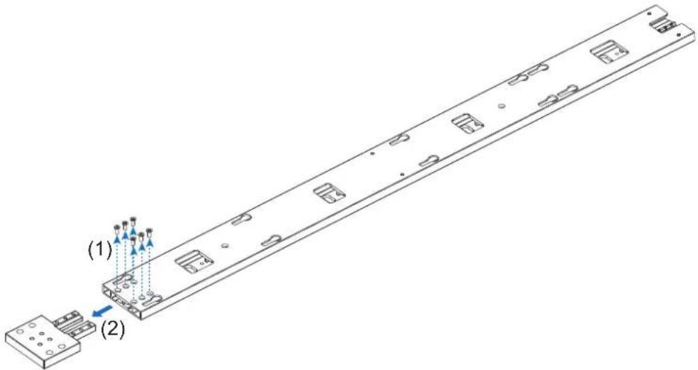
6. Install the mounting bars
(1) Install the mounting bars on the anchor points on the wall.
(2) Check the distance between the mounting bars using the alignment bars.
4 x 4 frame set
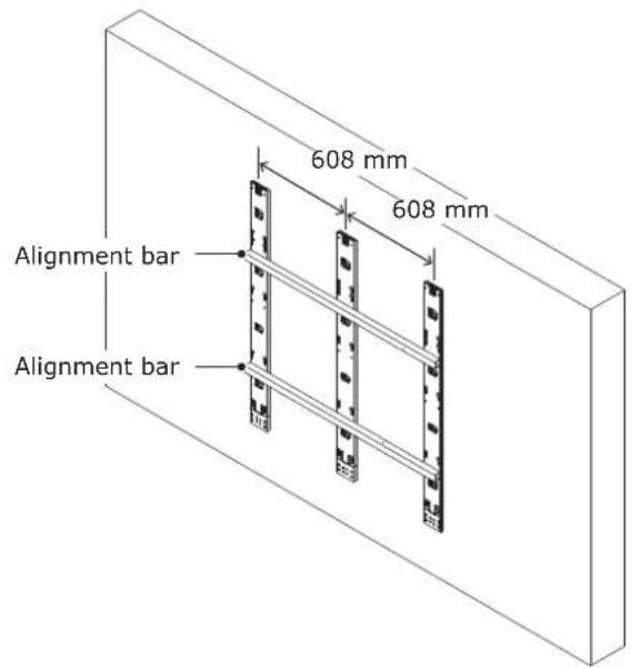
5 x 5 frame set

6 x 6 frame set

8 x 8 frame set

(3) Check the evenness using a spirit level or a laser line level and the alignment bars together. Adjust the positions if required.
Wall mounted: Mounting bar installation (4 x 4 frame set)

7. Install the power bar
Remove the power bar cover and install the power bar using Power bar screw (M8) screws.
How to remove the power bar cover
Sliding the power bar cover for removing. Power bar cover can slide left or right.
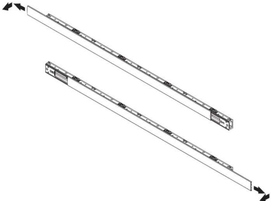

When using the 8 x 8 frame set, use the power bar connecting part to install the power bar.

8. Install the cabinet hanger pins to the back of the cabinets
The following drawings indicate where Hangar pins are required. Insert the Hangar pins until the pitch of the screws is no longer visible.
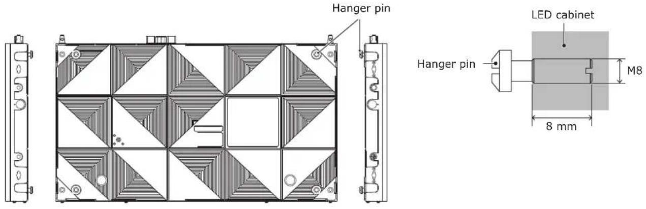
Cabinet hanger pins installation position
4 x 4 frame set 5 x 5 frame set

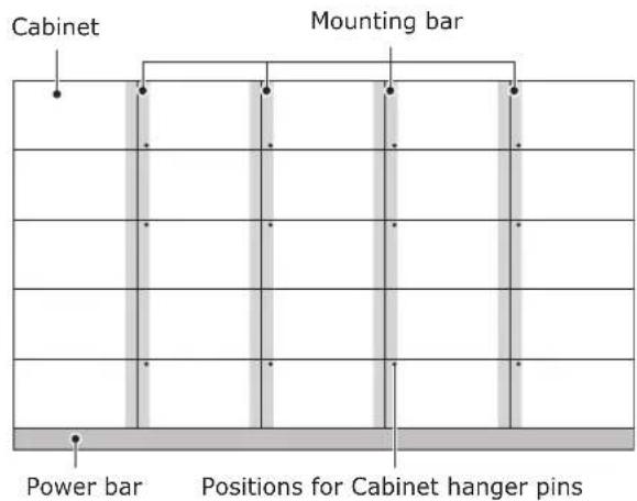
6 x 6 frame set

8 x 8 frame set

9. Install the cabinets
Hook the hanger pins, which have been inserted into the cabinets, into the holes on the mounting bars starting from the lowest row.

Fix temporarily the cabinets of the first row to the power bar.

Hook the hanger pins of the cabinets of the second row to the mounting bars.
Secure the LED cabinets together using screws for connecting cabinets. Do not tighten the screws completely.

After you have installed two rows of cabinets, align the surfaces of the cabinets using the Adjustment plates.

Adjust the position of the cabinet by turning the vertical alignment screw and the back in the center of the vertical alignment screw (cabinet hanger pin) with a flathead screwdriver.

When the cabinets' surfaces are aligned, securely tighten the cabinets of the first row to the power bar, the cabinets of the first row together, as well as the cabinets of the first row with the cabinets of the second row. Remove the Adjustment plates after the screws have been tightened.
Follow the same procedure to install the next row of cabinets and align their surfaces.
Connect the power cord and the LAN cable from the opening at the back of the power bar.
How to connect the power cord (FA series)

| A External power input |
| B Terminal in Power bar |
| C1 Ethernet port main data |
| C2 Ethernet port backup data |
| D1 Data cable main |
| D2 Data cable backup |
Connect the D1 main data cable to the left LAN port (C1 Ethernet port main data) and the D2 backup data cable to the right LAN port (C2 LAN Ethernet port backup data) of the power bar.
How to connect the power cord (FE series)

| A External power input |
| B Terminal in Power bar |
| C Power supply socket in Power bar |
| D Data cable |

WARNING
Pay attention to the wire colors of the power cord when connecting the cord. If the cables are not connected correctly, it may lead to a fire or an electrical shock.
Blue (N)
Brown (L)
Yellow green (Ground)

CAUTION:
When attaching two cables with one screw, place the ring terminals of the cables back to back.

Install the power bar cover.

Insert the slot nut into the overframe and align it with the marking line and fix them with screw for overframe screws.
Use overframe screws (M4 x 4) for the right side and overframe screws (M4 x 8) for the rest.

Install the corner parts to the corner frame top and install it on the top of the cabinets.
Slot nut installation locations

4 x 4 frame set

5 x 5 frame set

6 x 6 frame set

8 x 8 frame set
Screw for overframe M4×4
Screw for overframe M4×8
10. Assembly diagrams
4 x 4 frame set

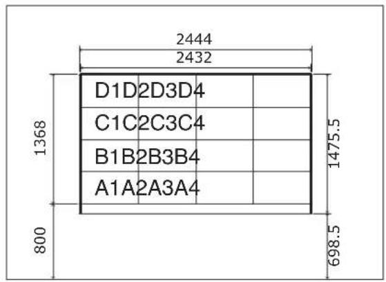


5 x 5 frame set


6 x 6 frame set
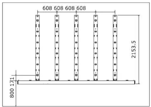


8 x 8 frame set


11. Installation without a frame set
An example of installation when using the brackets is shown below. Please prepare the bracket by yourself. Ask a technician or your retailer for the installation procedure when not using the brackets.
Install the brackets to the frame as shown in the figure below.
Use screws with a length adapted to the cabinet thickness (30 mm). Use also brackets with a sufficient thickness to hold the screws.

For installation, please refer to the "9. Install the cabinets".
12. Wiring
(1) Maximum number of signal connections
The maximum number of connections per LAN cable is shown below.
| Product name Maximum number of connections | Product name Maximum number of connections |
| LD-FA092 2 modules LD-FE092 2 modules | |
| LD-FA122 5 modules LD-FE122 5 modules | |
| LD-FA152 7 modules LD-FE152 7 modules | |
| LD-FA192 10 modules LD-FE192 10 modules | |
| LD-FA252 20 modules LD-FE252 20 modules | |
| LD-FA312 30 modules LD-FE312 30 modules | |
| LD-FA382 40 modules LD-FE382 40 modules |

CAUTION
The maximum number of connections may differ depending on the connected LED controller. Therefore, check the specifications of the LED controller you are using.
Ask a technician or your retailer for more details.
(2) Maximum number of power connections

CAUTION
Exceeding the maximum capacity may generate smoke or cause a fire.
Check the voltage used and do not exceed the connection limits shown below.
| Product name 100 - 120 V AC 200 - 240 V AC | |
| LD-FA092 10 modules 18 modules | |
| LD-FA122 13 modules 25 modules | |
| LD-FA152 13 modules 25 modules | |
| LD-FA192 13 modules 25 modules | |
| LD-FA252 13 modules 25 modules | |
| LD-FA312 13 modules 25 modules | |
| LD-FA382 13 modules 25 modules |
| Product name 100 - 120 V AC 200 - 240 V AC | |
| LD-FE092 10 modules 18 modules | |
| LD-FE122 13 modules 25 modules | |
| LD-FE152 13 modules 25 modules | |
| LD-FE192 13 modules 25 modules | |
| LD-FE252 13 modules 25 modules | |
| LD-FE312 13 modules 25 modules | |
| LD-FE382 13 modules 25 modules |
(3) Connection when using a wall-mount frame
This connection is an example of connection when using the maximum capacity.
The power cable corresponding to the yellow part needs to be prepared by the customer.
Please connect considering the capacity of the switchboard and the inrush current specification.
FA series
4 x 4 frame set
![graph TD A["HDMI"] --> B["Controller (MCTRL660Pro)"] C["DVI"] --> B D["Controller (MCTRL660Pro)"] --> B B --> E["AC POWER"] style A fill:#f9f,stroke:#333 style C fill:#f9f,stroke:#333 style D fill:#f9f,stroke:#333 style E fill:#ccf,stroke:#333](/content/2026/08/1614070/images/8b46c92ec0a7c4e6fa1b1fcf213defaa904b5498ebaaaf1b1b921cd3dc548bc0.jpg)
| 4×4 frame set AC 100V AC 200V | |||
| Number of power system | 2 | 2 | |
| Current rating per 1 mod | dule | 1.5 A 0.8 A | |
| per power system | 12.0 A 6.4 A | ||
| per frame set | 24.0 A 12.8 A | ||
| Inrush current per 1 mod | dule | 100 A 200 A | |
| 25°C Cold start | per power system | 800 A 1600 A | |
| Pulse width: 3ms | per frame set | 1600 A 3200 A | |
5 x 5 frame set
![graph TD A["HDMI"] --> B["Controller (MCTRL660Pro)"] C["DVI"] --> B D["Controller (MCTRL660Pro)"] --> B B --> E["AC POWER"] style A fill:#f9f,stroke:#333 style C fill:#f9f,stroke:#333 style D fill:#f9f,stroke:#333 style E fill:#ccf,stroke:#333](/content/2026/08/1614070/images/4365f5eecddf370c3df6409eac2ad5bb750a98ef75dbe1129b0d32a525994fa7.jpg)
| 5×5 frame set AC 100V AC 200V | |||
| Number of power system | 3 | 3 | |
| Current rating per 1 mod | dule 1.5 A 0.8 A | ||
| per power system 7.5 A (1 System)15.0 A (2 Systems) | 4.0 A (1 System)8.0 A (2 Systems) | ||
| per frame set 37.5 A 20.0 A | |||
| Inrush current per 1 mod25°C Cold startPulse width: 3ms | dule 100 A 200 A | ||
| per power system 500 A (1 System)1000 A (2 Systems) | 1000 A (1 System)2000 A (2 Systems) | ||
| per frame set 2500 A 5000 A | |||
6 x 6 frame set (0.9 mm pitch)
![graph TD A["AC POWER"] --> B["Controller (MCTRL 4K)"] B --> C["HDMI"] B --> D["DVI"] B --> E["Controller (MCTRL 4K)"] E --> F["HDMI"] E --> G["DVI"] E --> H["Controller (MCTRL 4K)"] H --> I["AC POWER"] style A fill:#f9f,stroke:#333 style B fill:#bbf,stroke:#333 style C fill:#dfd,stroke:#333 style D…](/content/2026/08/1614070/images/64bf2dc2c4149ce53db000f1b3e2a90a5a788767afbbd4fc2ecacb1638ea5f3f.jpg)
| 6×6 frame set (0.9 mm pitch) AC 100V AC 200V | |||
| Number of power system | 3 | 3 | |
| Current rating per 1 mod | dule 2.0 A 1.1 A | ||
| per power system 24.0 A | 13.2 A | ||
| per frame set 72.0 A 39.6 A | |||
| Inrush current per 1 mod | dule 100 A 200 A | ||
| 25°C Cold start | per power system 1200 A | 2400 A | |
| Pulse width: 3ms | per frame set 3600 A 7200 A | ||
6 x 6 frame set (1.9 mm pitch)
![graph TD A["HDMI"] --> B["Controller (MCTRL660Pro)"] C["DVI"] --> B D["Controller (MCTRL660Pro)"] --> B B --> E["AC POWER"] E --> F["Output"] style A fill:#f9f,stroke:#333 style C fill:#f9f,stroke:#333 style D fill:#f9f,stroke:#333 style B fill:#bbf,stroke:#333 style E fill:#bbf,stroke:#333 style F…](/content/2026/08/1614070/images/591c70385ad2933d2a4e93e1083e1a373fec569e2684115708d8889130f4e8d5.jpg)
| 6×6 frame set (1.9 mm pitch) AC 100V AC 200V | |||
| Number of power system | 3 | 3 | |
| Current rating per 1 mod | dule 1.5 A 0.8 A | ||
| per power system 18.0 A | 9.6 A | ||
| per frame set 54.0 A 28.8 A | |||
| Inrush current per 1 mod | dule 100 A 200 A | ||
| 25°C Cold start | per power system 1200 A | 2400 A | |
| Pulse width: 3ms | per frame set 3600 A 7200 A | ||
8 x 8 frame set (1.2 mm pitch)
![graph TD A["AC POWER"] --> B["Controller (MCTRL 4K)"] B --> C["HDMI → DVI"] B --> D["Controller (MCTRL 4K)"] C --> E["AC Power"] D --> E style A fill:#f9f,stroke:#333 style B fill:#bbf,stroke:#333 style C fill:#dfd,stroke:#333 style D fill:#dfd,stroke:#333](/content/2026/08/1614070/images/3282e4eefa3078580a1e8827b8171f2f8b32740fa993a58d243d20fb3b9f9add.jpg)
| 8×8 frame set (1.2 mm pitch) AC 100V AC 200V | |||
| Number of power system | 8 | 8 | |
| Current rating per 1 mod | dule 1.5 A 0.8 A | ||
| per power system 12.0 A | 6.4 A | ||
| per frame set 96.0 A 51.2 A | |||
| Inrush current per 1 mod | dule 100 A 200 A | ||
| 25°C Cold start | per power system 800 A | 1600 A | |
| Pulse width: 3ms | per frame set 6400 A | 12800 A | |
8 x 8 frame set (2.5 mm pitch)
![graph TD A["AC POWER"] --> B["HDMI → Controller (MCTRL660Pro)"] A --> C["HDMI → Controller (MCTRL660Pro)"] B --> D["DVI →"] C --> E["DVI →"] D --> F["Green Arrow Down"] E --> G["Green Arrow Down"] F --> H["Red Arrow Up"] G --> I["Red Arrow Up"] H --> J["Green Arrow Up"] I --> K["Green Arrow Up"] J -…](/content/2026/08/1614070/images/851ad8561c8094f544f51434536a611f9104a706d23e98accda3c548c04d5f12.jpg)
| 8×8 frame set (2.5 mm pitch, 3.8 mm pitch) AC | 100V AC 200V | ||
| Number of power system | 8 | 8 | |
| Current rating per 1 mo | dule 1.5 A 0.8 A | ||
| per power system 12.0 A | 6.4 A | ||
| per frame set 96.0 A 51.2 A | |||
| Inrush current per 1 mo | dule 100 A 200 A | ||
| 25°C Cold start | per power system 800 A | 1600 A | |
| Pulse width: 3ms | per frame set 6400 A | 12800 A | |
FE series
4 x 4 frame set
![graph TD A["HDMI"] --> B["Controller (MCTRL660Pro)"] C["DVI"] --> B B --> D["AC POWER"] style A fill:#f9f,stroke:#333 style C fill:#bbf,stroke:#333 style D fill:#dfd,stroke:#333](/content/2026/08/1614070/images/b34d73418a54505384b25ac66274093f657b4899e47c5312d02931a3f1b3a16f.jpg)
| 4×4 frame set AC 100V AC 200V | |||
| Number of power system | 2 | 2 | |
| Current rating per 1 mod | dule | 1.5 A 0.8 A | |
| per power system | 12.0 A 6.4 A | ||
| per frame set | 24.0 A 12.8 A | ||
| Inrush current per 1 mod | dule | 50 A 100 A | |
| 25°C Cold start | per power system | 400 A 800 A | |
| Pulse width: 3ms | per frame set | 800 A 1600 A | |
5 x 5 frame set
![graph TD A["AC POWER"] --> B["Controller (MCTRL660Pro)"] B --> C["HDMI"] B --> D["DVI"] C --> E["Red Arrow Down"] D --> F["Red Arrow Up"] E --> G["Blue Arrow Down"] F --> H["Blue Arrow Up"] G --> I["Red Arrow Down"] H --> J["Red Arrow Up"] I --> K["Red Arrow Down"] J --> L["Red Arrow Up"] K --> M["Y…](/content/2026/08/1614070/images/6d297dcbd6aa0d6bcf9a511f66a38a883fe14fe33a6d523dd04a7e51ed634f8c.jpg)
| 5×5 frame set AC 100V AC 200V | |||
| Number of power system | 3 | 3 | |
| Current rating per 1 mod | dule 1.5 A 0.8 A | ||
| per power system 7.5 A (1 System)15.0 A (2 Systems) | 4.0 A (1 System)8.0 A (2 Systems) | ||
| per frame set 37.5 A 20.0 A | |||
| Inrush current per 1 mod25°C Cold startPulse width: 3ms | dule 50 A 100 A | ||
| per power system 250 A (1 System)500 A (2 Systems) | 500 A (1 System)1000 A (2 Systems) | ||
| per frame set 1250 A 2500 A | |||
6 x 6 frame set (0.9 mm pitch)
![graph TD A["AC POWER"] --> B["HDMI → Controller (MCTRL 4K)"] A --> C["DVI → Controller (MCTRL 4K)"] B --> D["Blue arrows indicate direction of AC power"] C --> E["Green arrows indicate direction of AC power"] D --> F["Red arrows indicate direction of AC power"] E --> G["Red arrows indicate direction…](/content/2026/08/1614070/images/0215a52bd470eb78cc76de7f33f78f4e9e4b981be346b4f9c1b3771930a2cbf1.jpg)
| 6×6 frame set (0.9 mm pitch) AC 100V AC 200V | |||
| Number of power system | 3 | 3 | |
| Current rating per 1 mod | dule 2.0 A 1.1 A | ||
| per power system 24.0 A | 13.2 A | ||
| per frame set 72.0 A 39.6 A | |||
| Inrush current per 1 mod | dule 50 A 100 A | ||
| 25°C Cold start | per power system 600 A | 1200 A | |
| Pulse width: 3ms | per frame set 1800 A 3600 A | ||
6 x 6 frame set (1.9 mm pitch)
![graph TD A["AC POWER"] --> B["Controller (MCTRL660Pro)"] B --> C["HDMI"] B --> D["DVI"] C --> E["Red Arrow 1"] C --> F["Red Arrow 2"] C --> G["Red Arrow 3"] D --> H["Red Arrow 4"] D --> I["Red Arrow 5"] D --> J["Red Arrow 6"] E --> K["Blue Arrow 1"] F --> L["Blue Arrow 2"] G --> M["Blue Arrow 3"] H…](/content/2026/08/1614070/images/0364c74da32620fe803c8e8e87c3c56552f3f44d337962fd86798b3c89b3c1ce.jpg)
| 6×6 frame set (1.9 mm pitch) AC 100V AC 200V | |||
| Number of power system | 3 | 3 | |
| Current rating per 1 mod | dule 1.5 A 0.8 A | ||
| per power system 18.0 A | 9.6 A | ||
| per frame set 54.0 A 28.8 A | |||
| Inrush current per 1 mod | dule 50 A 100 A | ||
| 25°C Cold start | per power system 600 A | 1200 A | |
| Pulse width: 3ms | per frame set 1800 A | 3600 A | |
8 x 8 frame set (1.2 mm pitch)
![graph TD A["Controller (MCTRL 4K)"] --> B["AC POWER"] B --> C["HDMI →"] B --> D["DVI →"] C --> E["Red Arrow 1"] C --> F["Red Arrow 2"] C --> G["Blue Arrow 3"] D --> H["Blue Arrow 4"] E --> I["Red Arrow 5"] F --> J["Blue Arrow 6"] G --> K["Red Arrow 7"] H --> L["Red Arrow 8"] I --> M["Blue Arrow 9"]…](/content/2026/08/1614070/images/b496f501af1a946e693f37bb2b98448532a33de4a8e23562c87d60c72812dce7.jpg)
| 8×8 frame set (1.2 mm pitch) AC 100V AC 200V | |||
| Number of power system | 8 | 8 | |
| Current rating per 1 mod | dule 1.5 A 0.8 A | ||
| per power system 12.0 A | 6.4 A | ||
| per frame set 96.0 A 51.2 A | |||
| Inrush current per 1 mod | dule 50 A 100 A | ||
| 25°C Cold start | per power system 400 A | 800 A | |
| Pulse width: 3ms | per frame set 3200 A | 6400 A | |
8 x 8 frame set (2.5 mm pitch)
![graph TD A["AC POWER"] --> B["MCTRL660Pro"] C["HDMI"] --> B D["DVI"] --> B B --> E["Channel 1"] B --> F["Channel 2"] B --> G["Channel 3"] B --> H["Channel 4"] B --> I["Channel 5"] B --> J["Channel 6"] B --> K["Channel 7"] B --> L["Channel 8"] B --> M["Channel 9"] B --> N["Channel 10"] B --> O["Chann…](/content/2026/08/1614070/images/c7af29d88a52f0ee15e3cfa0302547e5b2650de4f2b2000b81e74b9d7a3c4438.jpg)
| 8×8 frame set (2.5 mm pitch, 3.8 mm pitch) AC | 100V AC 200V | ||
| Number of power system | 8 | 8 | |
| Current rating per 1 mod | dule 1.5 A 0.8 A | ||
| per power system 12.0 A | 6.4 A | ||
| per frame set 96.0 A 51.2 A | |||
| Inrush current per 1 mod | dule 50 A 100 A | ||
| 25°C Cold start | per power system 400 A | 800 A | |
| Pulse width: 3ms | per frame set 3200 A | 6400 A | |
Backside hole cabinet
There are holes on the back of the cabinet for passing signal cables and power cords.
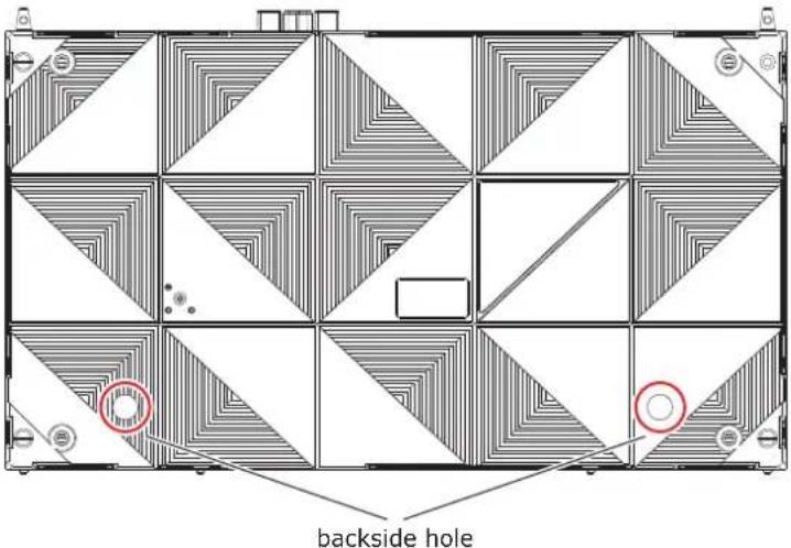
If the hole is not drilled, place a flathead screwdriver from inside the cabinet at the edge of the round recess and tap it lightly with a hammer to make a hole.
Cables for backside hole cabinet
Power cord

Remove the cable holder fixing ring attached to the LAN cable or power cord.
Remove the cable fixing part and move the cable holder to the end of the cable.
Attach the cable holder to the backside hole of the cabinet and attach the cable holder fixing ring from the outside of the cabinet.
Insert the cables.
Pinch the cable with the cable fixing part and attach it to the cable holder.

LAN cable power cord
[Info] For fixing the cable
Attache the buckle by screw.
Through the fastening tie lap and fix the cable to use fastening tie lap.

Connect the Power cable using WAGO.
Precautions on use of the power connector (WAGO)
When using the power cord connector (WAGO's product, WFR Series (WAGO 221), Models WFR-2 and WFR-3), respect the following precautions.
WAGO 221

* Visiting WAGO's homepage for more details is recommended.

WARNING
• Always use the connector indoors (in a location not affected by moisture).
- Use the connector by respecting the installation precautions. If the connector is not used correctly, it may lead to a fire or an electrical shock.
Installation precautions
- Wire sheath peeling

CAUTION
Be sure to peel off the wire sheath over the specified length.

CAUTION
Do not use the connector with the core wires being sinuous.
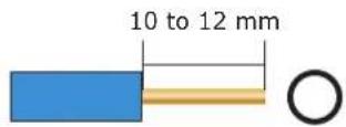


Lever operation is necessary even for connection of a solid core wire.
- Wire sizes
Wire sizes compatible with the power connector (WAGO) are as follows.
Solid core: 1.6 to 2.0 mm
IV 7-stranded core: 2.0 to 3.5 mm 2
Flexible stranded core: 2.0 to 3.5 mm 2
- When reconnecting a wire once disconnected, cut off the wire end and newly peel off the sheath.

CAUTION
- When reconnecting a wire once disconnected, cut off the wire end and newly peel off the sheath.
- If the disconnected wire is reconnected without this processing, it may heat up and burn out.
Newly peel off the sheath. End of disconnected wire: More or less damaged.

How to connect the power cord
(1) Raise the lever. (2) Insert the wire. (3) Return the lever to its
previous position.
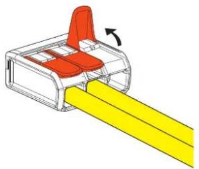


CAUTION
Insufficient insertion may cause poor electricity conduction and heat generation.
Power code connection checking
- Perform checking for correct and proper connection.
Lightly pull on the wires one by one to check that they will not be pulled out.
Check visually


WARNING
Pay attention to the wire colors of the power cord when connecting the cord. If the cables are not connected correctly, it may lead to a fire or an electrical shock.
Blue (N)
Brown (L)
Yellow green (Ground)
(4) LAN cable connection
Connect the LAN cables for the signal between the LED modules. Use the through holes to pass the cables between the modules.

[Connection example] Connecting from bottom to top using multiple ports
FA series
Connect the master connectors of the interface connectors to the master connectors, and the slave connectors to the slave connectors.

FE series

13. Installing the pixel card

CAUTION
- The pixel cards contain powerful magnets. If magnetic cards come close to the pixel cards, the data contained within may be damaged. Therefore, do not carry any magnetic card when installing the pixel cards.
- When installing the pixel cards, pay attention not to damage them against the pixel cards already installed or other objects. Otherwise, the video may not be displayed properly.
• Take measures against static electricity when installing the pixel card. Do not touch the LED display areas and the back of the pixel card. - Check that the power supply to the LED modules is cut before starting the work.
- Before installing or removing pixel cards, please ensure the wall has been powered off for 1 or 2 hours. Otherwise the thermal expansion of pixel cards increases the risk of damaging them during removal or insertion.
- If installation is not successful, please use the maintenance tool. (see English-88)
The arrows (↑) at the back of the pixel cards indicate the upper side.
Install the pixel card into the cabinet with the four guide holes of the pixel card aligned with the four guide pins of the cabinet (four pins for each pixel card). The pixel card is secured by the 4 magnets on each pixel card.
Insert into the guide holes


Check that all the connections are completed, and then turn on the LED modules and the LED controller.
![graph TD A["Power distributor"] --> B["LED controller"] B --> C["Computer"] B --> D["Video signalControl signal"] B --> E["Grid of sensors"] style A fill:#f9f,stroke:#333 style B fill:#ccf,stroke:#333 style C --> F["Computer"] style D --> G["Video signalControl signal"] style E fill:#dfd,stroke:#333](/content/2026/08/1614070/images/d28ff0907f6807253ac081b835bfcd83847c4bd14fc5bbf4b896a6008604e32e.jpg)

WARNING
Pay attention to the wire colors of the power cord when connecting the cord. If the cables are not connected correctly, it may lead to a fire or an electrical shock.
Blue (N)
Brown (L)
Yellow green (Ground)

CAUTION
When using LAN cables of 60 m to 100 m in length, the product may not operate correctly depending on the quality of the cables. In such a case, it is recommended to use optical-fiber cables. Ask a technician or your retailer for more details.
Preparing for using NovaLCT software
Perform the setting using the NovaLCT control software by Novastar.
Connect the supplied USB memory to the computer. Start NovaLCT*.exe.
After it has started, install it following the software instructions.
The NovaLCT preparation is complete.

CAUTION
For NovaLCT*.exe, be sure to use the file contained in the supplied USB drive.
Using a NovaLCT*.exe file different than the one in the supplied USB drive may lead to malfunction.
Log in with the administrator privileges.
Display the login screen as follows: User(U) → Advanced Synchronous System UserLogin(A).
Enter the password ("admin" by default) to log in with the administrator privileges.
To change the password, go to User(U) → Change Password(U) with the administrator privileges.

CAUTION
Do not forget the new password after it has been changed.
Enter the screen configuration menu
(1) Click "Screen Configuration" (a).

(2) Check the port in "Select Communication Port", and then click the "Next" button (b).

(b)
Module connection settings
Start NovaLCT and log in with the administrator privileges.
In the Screen Configuration screen that is displayed, select the "Screen Connection" tab (a).


CAUTION
Do not change the settings in the "Receiving Card" tab. Otherwise, the video may not be displayed properly.
Select "Standard Screen" under "Screen Type" (b).
The settings in "Sending Card Number" (c) and "Ethernet Port No." (d) vary depending on the connected LED controller.

Enter the value in the table below under "Receiving Card Size" (e).
| Product name | LD-FA092LD-FE092 | LD-FA122LD-FE122 | LD-FA152LD-FE152 | LD-FA192LD-FE192 |
| Pixel pitch 0.9 mm | 1.2 mm 1.5 mm | 1.9 mm | ||
| Number of displayed pixels (resolution/module) | Width 640Height 360 | Width 480Height 270 | Width 384Height 216 | Width 320Height 180 |
| Product name | LD-FA252LD-FE252 | LD-FA312LD-FE312 | LD-FA382LD-FE382 |
| Pixel pitch 2.5 mm | 3.1 mm 3.8 mm | ||
| Number of displayed pixels (resolution/module) | Width 240Height 135 | Width 192Height 108 | Width 160Height 90 |
[Columns/Rows] Enter the number of installed screens under "Columns/Rows" (f) (the number of vertically installed screens in Columns, and the number of horizontally installed screens in Rows).
[Configuration example]
The setting values are given for the following example where 16 are installed in a 4 (columns) x 4 (rows) configuration connecting from bottom to top using multiple ports.
![graph TD A["Computer"] --> B["Switch"] B --> C["Node 1"] B --> D["Node 2"] B --> E["Node 3"] B --> F["Node 4"] B --> G["Node 5"] B --> H["Node 6"] B --> I["Node 7"] B --> J["Node 8"] B --> K["Node 9"] B --> L["Node 10"] B --> M["Node 11"] B --> N["Node 12"] B --> O["Node 13"] B --> P["Node 14"] B --…](/content/2026/08/1614070/images/8ca0f07fb8b4e32a6c2f4c7631d1e15084526b7d0e8c17d07e59f5f229791043.jpg)
(1) With a pixel pitch of 1.25 mm, enter Width=480 and Height=270 under "Receiver Card Size" (e). Do not use the buttons located next to the values.

(2) Since the configuration is 4 (columns) x 4 (rows), enter Columns=4 and Rows=4. A 4 (columns) x 4 (rows) screen configuration is displayed.
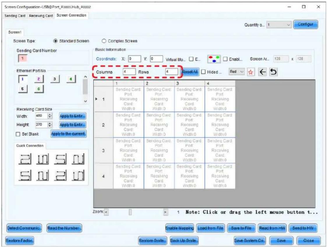
(3) If multiple LED controllers are used, select the number of the connected LED controllers. Since only one controller is used in this example, it is not necessary to set "Sending Card Number" (c).
(4) Configure the connection.
The system is connected to port 1 of the LED controller.
Select "1" (port 1) under "Ethernet Port No." (d).
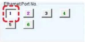
Select the cabinet at the bottom left with the mouse, and then select the other cabinets up to the top cabinet.
Then select Port2 and select the cabinets from the bottom to the top as you did for Port1.
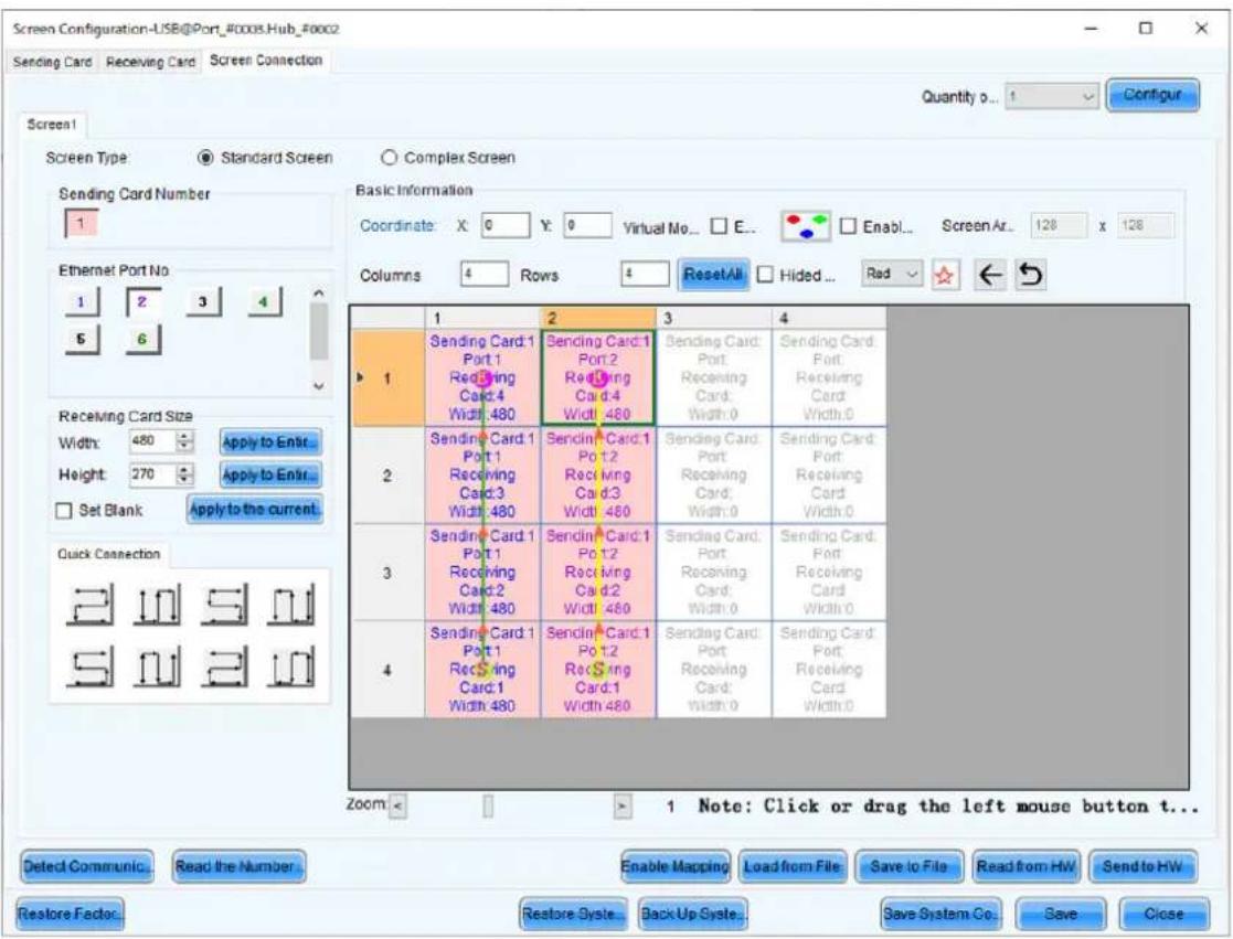
Follow the same procedure for Port3 and Port4.
(5) Save the settings.
(a) Click the "Send to HW" button (h). When the dialog box indicating that the process finished successfully is displayed, click OK.
(b) Check that the image is correctly displayed, and then click the "Save" button (i). When the screen indicating that the process finished successfully is displayed, click OK.
The setting of the screen configuration is complete. Click the "Close" button (j) to close the Screen Configuration screen.
Receiving card settings
(1) The Screen Configuration screen is displayed. Select the "Receiving Card" tab (a).

(2) Click "Load from File" (b).
(3) Select the configuration file (rcfgx file) you want to load to the receiving card. A screen like the following appears when the loading process is complete.

(4) Click "Send to Receiving Card" (c).
(5) Click "Save" (d).
Update the Calibration Data
(1) Login as Advanced User.
(2) Click the "Calibration" button (a). Start calibration menu.


(3) Select the "Screen1" radio button.
(4) Click on the "Manage Coefficients" tab (b).

(5) Click on "Module Flash".
Result: The module flash options will appear.
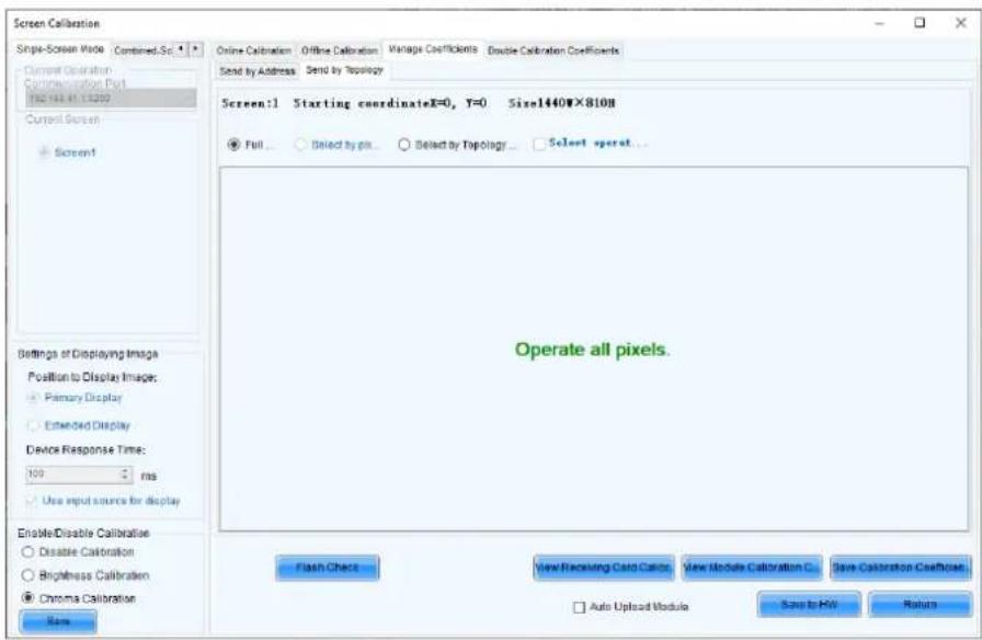
Select whether you want the entire screen or individual modules.
Full screen: Select this option when installing.
Module Flash (Select by Topology or list): Select this option when replacing pixel cards, etc.
Refer to "Module setting method when performing Module Flash
for individual modules" (English-70) for the setting method of target modules.
If "Adjusting the colors on a part of the screen" has been performed on the area set for Module Flash, perform it again after Module Flash.
(6) Click the "View Module Calibration Coefficients" button.
Result: Pop-up message opens.

(7) Click "Save Calibration Coefficients to Receiving Card".
The pop-up message, that the data has been successfully stored to the Receiving cards, will appear. Result: The screen with the exchanged Pixel cards should look calibrated now.
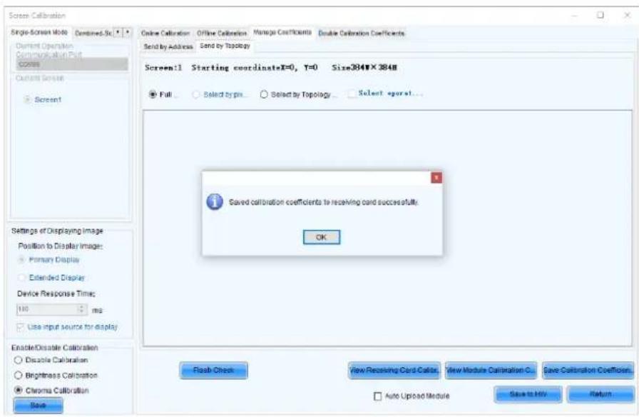
(8) Click on "Save to HW" button and go back to main window by clicking "OK" button.
(9) Check the calibration-state in the bottom left corner of Screen Calibration window: Enable/Disable Calibration.

(10) If calibration-setting "Disable Calibration" is chosen, switch to "Chroma Calibration" (c) to enable calibration and click on the "Save" button (d).
Result: While switching you will already see calibration effect.

(11) Close Screen Calibration windows by clicking on the "X".
Result: The calibration data update is complete.
Module setting method when performing Module Flash for individual modules
(1) Select "Select by Topology or List".
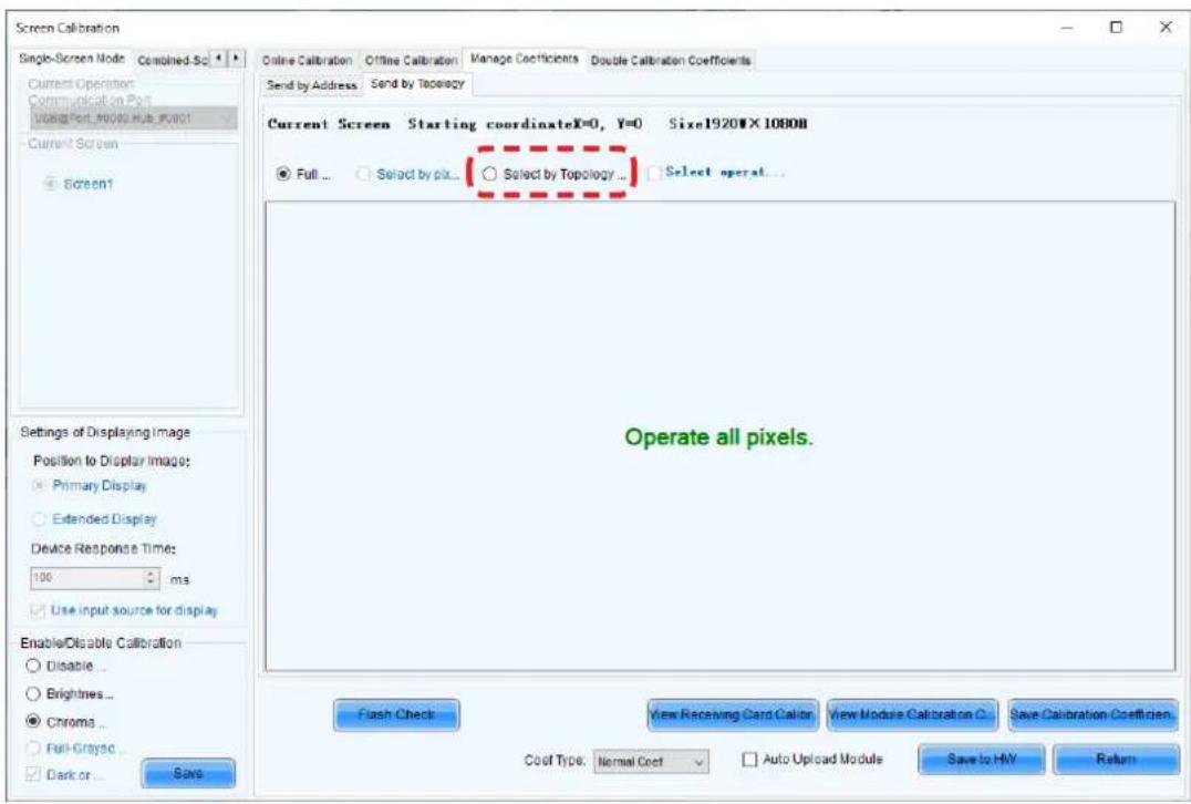
(2) Select the target module. Click inside the frame of the target module.

(3) The color of the selected module changes to yellow.

(4) Return to step (6) of "Update the Calibration Data".
What can be done with Auto Upload Module
When "Auto Upload Module" is set, if the power of the LED module is restarted after the pixel card replacement, the calibration data of all pixel cards in the module, including the pixel card that has been replaced, is automatically written to the receiving card, and the image is displayed according to this state.
Precautions related to the operation (Adjusting the colors on a part of the screen)
Set "Auto Upload Module" to off when performing "Adjusting the colors on a part of the screen".
(Uncheck "Auto Upload Module" and click "Save to HW".)
Since the calibration data adjusted with "Adjusting the colors on a part of the screen" is saved in the receiving card and used for the display, if "Auto Upload Module" is checked, the calibration data in all the pixels cards inside the module whose pixel card has been replaced is written to the receiving card when the power is turned on and the results of the adjustment performed with "Adjusting the colors on a part of the screen" is lost. Then, the calibration data in the pixel card is used to display the image.
NOTE:
In the case of the FA series, Auto Update Module works only with the receiving card on the master side. (Pay attention since it does not work with the receiving card on the slave side.)
Detailed procedure
To set Auto Update Module, it is necessary to set module IDs to each pixel card and to register these module IDs to the receiving card.
Once module IDs are set to the pixel cards, registration of the module IDs to the receiving card is performed with Module Flash.
Follow the procedure below to check that module IDs are set to the pixel cards.
You may also use the procedure below to set module IDs to the pixel cards if they are not already set.
Perform Module Flash again after setting module IDs to the pixel cards.
NOTE:
- Auto Update Module will not work with the receiving card on the slave side with the FA series even if it is set.
- It is not possible to set module IDs to the receiving card on the slave side with the FA series.
(1) Log in with the administrator privileges and select "Tool" - "Module ID setting".

(2) Click the "Refresh" button to check the module ID setting state. Module IDs are not set if "ID: NULL" is displayed.

(3) Click on the NovaLCT window and enter "admin". Click the "Generate" button.

(4) Module IDs are generated.
(5) Click the "Save to H/W" button to save the module IDs to both the pixel cards and the receiving card. You may click the "Refresh" button to check the setting state.

(6) Select "Calibration".

(7) Select the "Manage Coefficients" tab.

(8) Select "Module Flash".
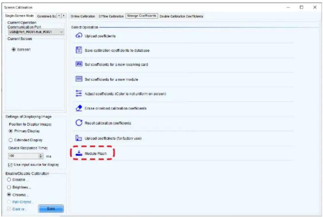
(9) Check the "Auto Upload Module" box.

(10) Click the "Save to HW" button.
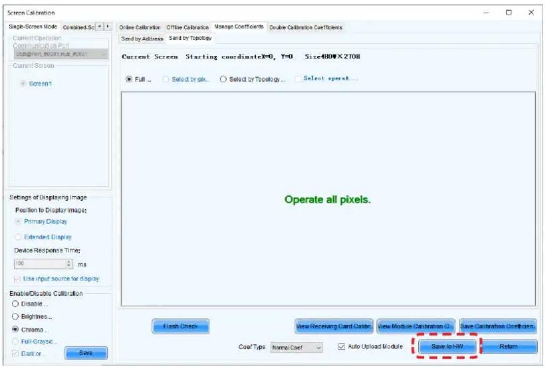
(11) Click the "Return" button to return to the previous screen.
You can adjust the brightness, the gamma correction value, and the color temperature.
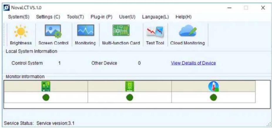
Click "Brightness" on the top screen to display the following window.

(e)

English - 77
Click "Advanced Settings" (M) (a) to expand the setting screen.
(1) Brightness
Set the brightness of the screen using the slider (b).
Increasing the value increases the brightness.
(2) Gamma correction
Set the gamma correction value using the slider (c).
Increasing the value makes the dark parts of the screen darker.
(3) Color temperature
Set the color temperature using the slider (d).
Increasing the value makes the colors more bluish, while reducing the value makes the colors more reddish.
When the setting is complete, click the "Save to HW" button to save the settings.
Line calibration
(1) Log in with the administrator privileges (English-60).
(2) On the tabs at the top of the window, click Tools > Quickly Adjust Dark or Bright Lines

(3) A screen like the figure below is displayed. Press the Shift + E keys. The gray window moves to the LED modules.
![Scan Brightness Adjustment Mode... Ctrl... Row... Row Column Class... Deseled Class... Drive... Show... Calculation Show... Screen data Window Color (48=0) Screen Brightness - Screw 1 SHIFT+F1:ShowH-side prompts SHIFT+E] Extended ModelCopy Mode SHIFT+H:ShowH-side windows No Video Source (The sending…](/content/2026/08/1614070/images/c026a1956a72bb1dab28f7693469ebaafff8adf564b10e5d40d8e8346d0d7803.jpg)
(4) Click "Module Mode" on the top left of the screen.

Enter the number of pixels inside one pixel card on the screen that pops up, and then click "OK".

| Product name | LD-FA092LD-FE092 | LD-FA122LD-FE122 | LD-FA152LD-FE152 | LD-FA192LD-FE192 |
| Number of displayed pixels (resolution/pixel card) | Width 160Height 180 | Width 120Height 135 | Width 96Height 108 | Width 80Height 90 |
| Product name | LD-FA252LD-FE252 | LD-FA312LD-FE312 | LD-FA382LD-FE382 |
| Number of displayed pixels (resolution/pixel card) | Width 60Height 135 | Width 48Height 90 | Width 40Height 45 |
Lines separating each pixel card are displayed.
LD-FA092, LD-FA122, LD-FA152, LD-FA192, LD-FA312, LD-FA382
LD-FE092, LD-FE122, LD-FE152, LD-FE192, LD-FE312, LD-FE382

LD-FA252, LD-FE252

(5) Specify the border between the pixel cards for which you want to perform line calibration by clicking on it or specifying a range. You may also adjust multiple locations at the same time.
LD-FA092, LD-FA122, LD-FA152, LD-FA192, LD-FA312, LD-FA382
LD-FE092, LD-FE122, LD-FE152, LD-FE192, LD-FE312, LD-FE382

LD-FA252, LD-FE252

< Tool icons used to select the adjustment range >

Clear effects: Resets the line calibration in the selected range.

Deselect: Deselects the range currently selected.

Clear all effects: Resets line calibration for all locations.
The selected adjustment range is also displayed on the LED modules. LD-FA092, LD-FA122, LD-FA152, LD-FA192, LD-FA312, LD-FA382, LD-FE092, LD-FE122, LD-FE152, LD-FE192, LD-FE312, LD-FE382
![[SHIFT+F1] ShowHide prompts [SHIFT+E] Extended Mode/Copy Mode [SHIFT+F] ShowHide windows 1-1 1-2 1-3 1-4 2-1 2-2 2-3 2-4 1-5 1-6 1-7 1-8 2-5 2-6 2-7 2-8 3-1 3-2 3-3 3-4 4-1 4-2 4-3 4-4 3-5 3-6 3-7 3-8 4-5 4-6 4-7 4-8](/content/2026/08/1614070/images/07f549496664041839788fad24e436d79242b86cd51512e79c9a2091d82cac30.jpg)
LD-FA252, LD-FE252
![[SHIFT+F1] Show+lide prompts [SHIFT+E] Extended Mode/Copy Mode [SHIFT+F]:Show+Hide windows 1-1 1-2 1-3 1-4 2-1 2-2 2-3 2-4 C = = = = = 3-1 3-2 3-3 3-4 4-1 4-2 4-3 4-4](/content/2026/08/1614070/images/ffc3707f2347b38cad9f84e2b69ed5f78f170676eab4283df41bf81a034687f1.jpg)
(6) Click the upward and downward arrows next to the input box at the bottom of the window to adjust the brightness of the selected locations.
LD-FA092, LD-FA122, LD-FA152, LD-FA192, LD-FA312, LD-FA382
LD-FE092, LD-FE122, LD-FE152, LD-FE192, LD-FE312, LD-FE382

Upward arrow: Increases the brightness (makes the dark lines less noticeable)
Downward arrow: Decreases the brightness (makes the bright lines less noticeable)
LD-FA252, LD-FE252

Upward arrow: Increases the brightness (makes the dark lines less noticeable)
Downward arrow: Decreases the brightness (makes the bright lines less noticeable)
(7) If you want to adjust other locations, click "Deselect" and specify again a range for the adjustment.
When the adjustment is complete, click "Save to HW" at the bottom of the screen.
LD-FA092, LD-FA122, LD-FA152, LD-FA192, LD-FA312, LD-FA382
LD-FE092, LD-FE122, LD-FE152, LD-FE192, LD-FE312, LD-FE382

LD-FA252, LD-FE252

Click "Yes" on the screen that pops up.
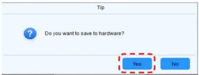
(8) The adjustment is complete when the following screen is displayed. Click "Close" to finish.

Note
If the line calibration settings are not updated on the screen after reading the calibration data, restart the LED modules to update the line calibration settings.
The screen brightness may decrease if dust or another foreign material is adhering to the surface of the pixel card.
The magnet used to install the pixel cards also attracts magnetic metal particles, such as iron powder.
Therefore, magnetic metal particles may adhere to areas near the magnet of the pixel card and the brightness homogeneity of the screen may decrease.
Cleaning should be performed regularly depending on the installation environment.
Required tools (example).

Soft brush
(animal hair brush to prevent static electricity)
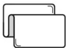
Soft cloth
(that does not generate static electricity)
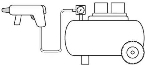
Air blower (compressor)
Cleaning method
a) Turn the LED displays off.
b) Use the soft brush to remove any dirt on the LED lamps and the masks. If these parts are very dirty, use the air blower to remove the dirt.
c) Use the soft cloth to remove the dirt on the screen surface.
d) Repeat the steps (b) and (c) to remove all the dirt.

CAUTION
- Do not use water or any other liquid.
- Do not use a stiff brush.
- Pay attention not to damage the LED lamps when using the soft brush, the air blower, or the soft cloth.

CAUTION
- Disconnect the power supply to the LED modules when performing the maintenance.
- Before installing or removing pixel cards, please ensure the wall has been powered off for 1 or 2 hours. Otherwise the thermal expansion of pixel cards increases the risk of damaging them during removal or insertion.
- Use the correct screwdriver for the shape of the screws when removing (loosening) or setting (tightening) the screws.
Pay attention not to drop the screws and the other parts you have removed.
Pay attention not to lose the removed screws since they will be reused.
Removing a pixel card
Remove the pixel card using the maintenance tool.

-1. Turn on the power switch.
-
Press the start button and the device will starts.
-
Put the maintenance tool flat onto the surface of the pixel card which you want to take off, make sure the device is tightly sucked with the pixel card.
-
Pull out the maintenance tool and pixel card vertically.
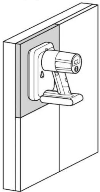

Be sure to perform "Update the Calibration Data" (English-67) after replacing a pixel card.

CAUTION:
- Check that the battery of the maintenance tool is fully charged before starting the work. Pixel card falls if the battery runs out. Hold the pixel card with your hand to support in case it falls.
- Do not turn the maintenance tool off until you hold the pixel card. Otherwise, the pixel card may fall and break.
Removing and installing the hub board
(1) Removing the hub board
(a) Disconnect the LAN cable from the hub board
(b) Remove the 16 screws securing the hub board with a Phillips screwdriver (No. 1).
(c) Since the hub board is connected to the power unit with pins and connectors, remove it by raising this part, as well as the part with the positioning holes. The status board and the hub board are connected with a cable.
Pay attention not to pull the hub board.
(d) Disconnect the cable from the hub board, and then remove the hub board.


CAUTION:
The hub board is connected to the status board with a flat cable. When removing the hub board, pay attention not to pull and damage the cable.
Disconnect the connector on the hub board, and then remove the hub board.
(2) Installing the hub board
Install the hub board into the cabinet following the procedure below.
(a) Connect the status board to the hub board using the cable.
(b) Install the hub board into the cabinet. Install it with the power unit pins and connectors aligned. Insert the pins and connectors completely and check that the hub board is securely attached and not bent.
(c) Tighten the 18 screws. Use a tightening torque of 3 ± 0.5 kgf · cm .
(d) Connect the LAN cable.
Replacing the power unit
The power unit dissipates heat through the cabinet. Apply some thermal paste on the back of the power unit to be replaced. Ask your retailer for more details on the types of thermal paste.
(a) Remove the hub board following the “(1) Removing the hub board” procedure on the previous page.
(b) Remove the four screws, and then remove the power hub board.
(c) Remove the two screws securing the power unit, and then replace the power unit.
(d) Install the power hub board, the protective sheet, and the hub board.
(e) Install the hub board following the "(2) Installing the hub board" procedure on the previous page.
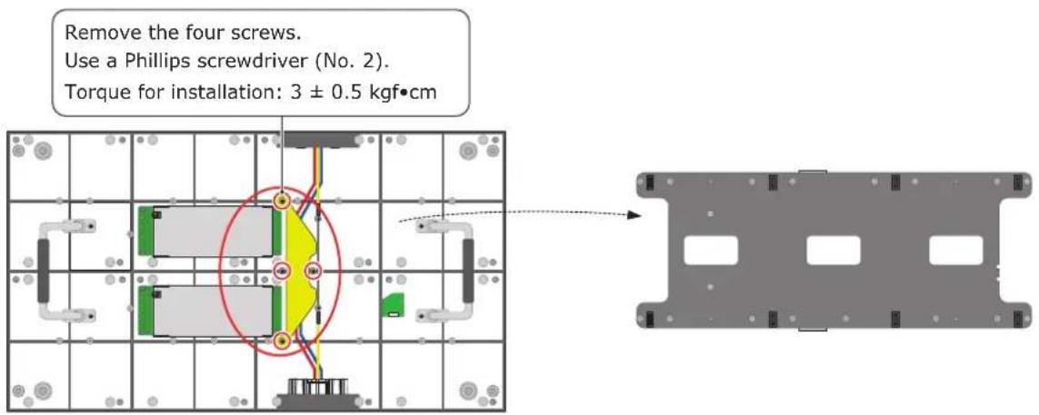


The FE series power supply unit is only on the bottom side.
Replacing the receiving card
Remove the receiving card from the hub board.
Remove the four screws securing the receiving card, and then remove the receiving card from the hub board.
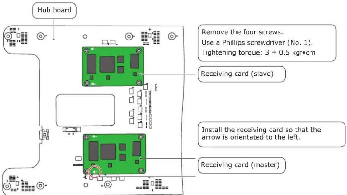
The FE series receiving card is (master) only.
Perform the following after replacing the receiving card.
Check the hardware program
While referring to "Updating the hardware program", check the version of the hardware program of the receiving card and update the hardware program if the version does not match the version of the modules whose receiving card has not been replaced.
Update the configuration data
While referring to "Saving the configuration data", read the configuration data from a module whose receiving card has not been replaced and save it as a file.
While referring to "Updating the hardware program", write the saved file of the configuration data to the receiving card that has been replaced.
Adjust the brightness, color temperature, and gamma
Perform "Image Setting" (English-77)

CAUTION:
With the FA series, the receiving card on the slave side must be configured the same way as on the master side.
Perform the "Check the hardware program", "Updating the configuration data", and "Adjust the brightness, color temperature, and gamma" procedures on the receiving card on the slave side.
Replace the LED controller
Before replacing the LED controller, check the version of the hardware program of the LED controller that will be replaced.
While referring to "Updating the LED controller hardware program", check the version of the hardware program of the controller.
Perform the following procedure after replacing the LED controller.
Check the hardware program
While referring to "Updating the LED controller hardware program", check the version of the hardware program of the LED controller after the replacement. If the version differs from the version of the hardware program of the LED controller before the replacement, update the hardware program.
Perform "Module connection settings" (English-61) again.
Adjust the brightness, color temperature, and gamma
Perform "Image Setting" (English-77)
Replace the control PC
If the control PC has been replaced, install NovaLCT (Preparingfor using NovaLCT software (English-60)).
- Display problems
| Problem Solution | |
| Nothing is displayed on all the LED modules. | Check that power is being supplied to the LED modules. |
| Check that the LED controller is turned on. | |
| Check that a video signal is being input to the LED controller. | |
| Check that a LAN cable is correctly connected between the LED controller and the LED module. | |
| Check that the brightness is not set to 0% (= not lit). | |
| Nothing is displayed on one LED module. | Check that a LAN cable is correctly connected between the LED controller and the LED module. |
| The receiving card inside the LED module may be broken.→ Check the status of the LED module by following the procedure in "State monitoring using the software". | |
| The power unit inside the LED module may be broken.→ Check the status of the LED module by following the procedure in "State monitoring using the software". | |
| No image is displayed on one pixel card. | Check that the contacts of the pixel card are correct (contacts of the hub board). |
| The pixel card may be broken. Replace it with a spare pixel card. | |
| Control (communication) is not possible. | Check that the communication cable is correctly connected between the computer and the LED controller. |
| Check that the LED controller is turned on. | |
| If the communication cable is a USB cable, check that the device driver runs correctly. | |
| The colors differ on one pixel card. | Adjust the brightness, gamma correction value, and color temperature with the "Image Setting" procedure.Perform the "Adjusting the colors on a part of the screen" procedure. Select the adjustment range using "Select by Pixel Area" described in (5)-2. |
| I want to adjust the color tone of the entire screen. | Perform the "Adjusting the colors on a part of the screen" procedure. Select the adjustment range using "Screen" described in (5)-1. |
| Bright lines or dark lines are visible between the pixel cards or between the modules. | Perform the "Line calibration" procedure. |
| The brightness or colors of a pixel card that has been replaced differ from the surrounding pixel cards. | Adjust the colors in the following order until the brightness and colors are the same as the surrounding pixel cards.Perform "Update the Calibration Data" (English-67).↓Perform "Image Setting" (English-77).↓Save the configuration data of the LED modules displaying the image normally ("Saving the configuration data") and write the saved configuration file ("Updating the configuration data").↓Perform "Image Setting" (English-77) again.↓Perform the "Adjusting the colors on a part of the screen" procedure. |
2. Adjusting the colors on a part of the screen
(1) Log in with the administrator privileges (English-60).
(2) Click "Calibration" (a). Start calibration menu.


(3) Check that "Chroma Calibration" (b) is selected and click the "Manage Coefficients" tab (c).

(4) Set "Extended Display" (d) under "Setting of Displaying Image", and then click "Adjust coefficients" (e).

(5) Select the range specification method from the three available methods depending on the calibration range. After setting the range, click "Next" to display the "Adjust Coefficients" screen.

(5)-1
Screen: Adjust the entire frame set.
The calibration settings reading starts after "Next" is clicked. A fair amount of time is required to read the data.
The "Adjust Coefficients" screen is displayed when the data has been read.
(5)-2
Select by Pixel Area: Adjust by pixels.

The screen used to specify the adjustment range is displayed.
Column Number: The position (pixel) on the horizontal axis of the starting point (top left) of the selection range
Row Number: The position (pixel) on the vertical axis of the starting point (top left) of the selection range
Width: The horizontal distance from the points specified with "Column Number" and "Row Number"
Height: The vertical distance from the points specified with "Column Number" and "Row Number"
For reference: When specifying one pixel card

| Product name | LD-FA092LD-FE092 | LD-FA122LD-FE122 | LD-FA152LD-FE152 | LD-FA192LD-FE192 |
| Pixel pitch 0.9 mm | 1.2 mm 1.5 mm | 1.9 mm | ||
| Number of displayed pixels (resolution/module) | Width 640Height 360 | Width 480Height 270 | Width 384Height 216 | Width 320Height 180 |
| Number of displayed pixels (resolution/pixel card) | Width 160Height 180 | Width 120Height 135 | Width 96Height 108 | Width 80Height 90 |
| Product name | LD-FA252LD-FE252 | LD-FA312LD-FE312 | LD-FA382LD-FE382 |
| Pixel pitch 2.5 mm | 3.1 mm 3.8 mm | ||
| Number of displayed pixels (resolution/module) | Width 240Height 135 | Width 192Height 108 | Width 160Height 90 |
| Number of displayed pixels (resolution/pixel card) | Width 60Height 135 | Width 48Height 90 | Width 40Height 45 |
Check that "Adjust Its Own Effect" is selected and click "Next" to start the calibration settings reading process.
The "Adjust Coefficients" screen is displayed when the data has been read.

(5)-3
Select by Topology or List: Adjust multiple modules
A screen with the display configuration is displayed. Specify the range of the modules you want to adjust.
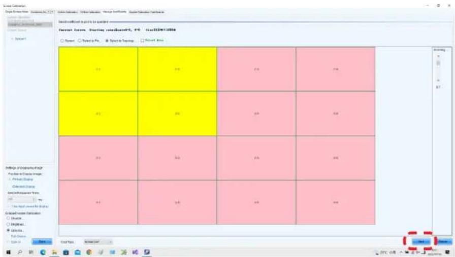
The calibration settings reading starts after "Next" is clicked.
The "Adjust Coefficients" screen is displayed when the data has been read.
(6) Adjust Coefficients screen
Click "Advanced Adjustment".

(7) Adjust the "Color adjustment of red, green and blue" parameters, and then adjust the "Color matching of red, green and blue" parameters.
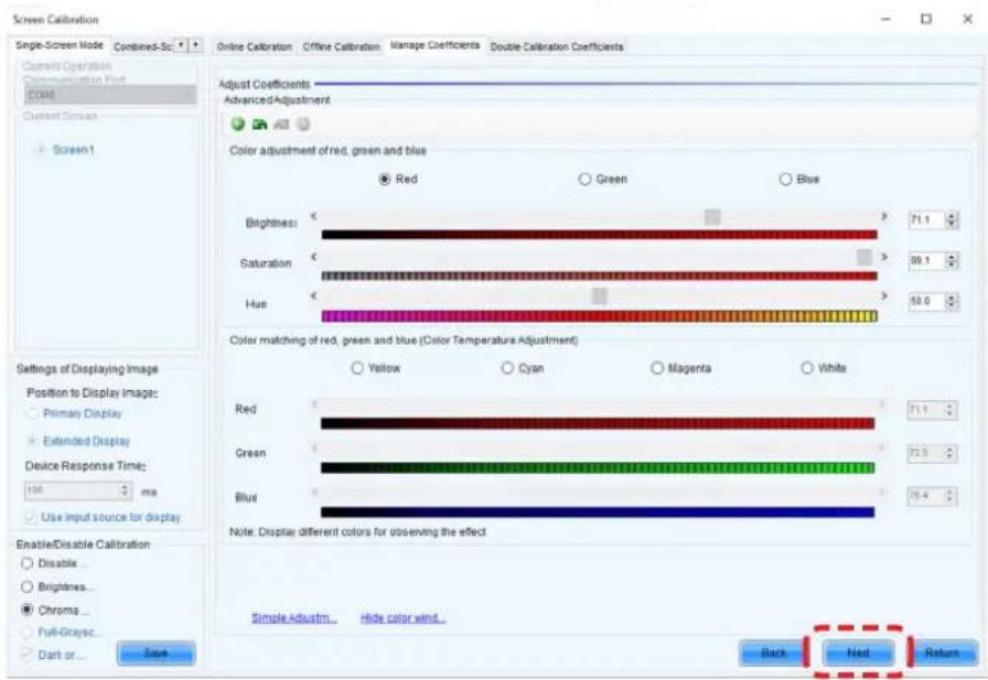
Click "Next" after you have finished the adjustment.
(8) Click "Save" to save the calibration settings you have adjusted.
(9) Click "Finish" to complete the procedure.

Note
- To return the calibration adjustment values to their default setting, perform the "Update the Calibration Data" procedure (English-67).
- The results of "Adjusting the colors on a part of the screen" are saved in the receiving card. They are not saved in the pixel card. When "Auto Upload Module" is on, the data adjusted with "Adjusting the colors on a part of the screen" and written in the receiving card is erased if the pixel card is replaced.
Set "Auto Upload Module" to off when performing "Adjusting the colors on a part of the screen". Refer to "4. Writing the calibration data from the receiving card to the pixel card" (English-154) if you want to write the calibration data to the pixel card after performing "Adjusting the colors on a part of the screen".
Image booster engine
By using the image booster engine, you will be able to improve the precision of the LED display colors and grayscale, and switch freely between display color gamuts.
The *.vglcx file used for the image booster engine is stored in the supplied USB memory key.

Click the "Image Booster Engine" button.

The "Image Booster Engine" screen is displayed.
Click the "Device Management" button.

The Device Management window opens.

Select the operation target.
When the selection is made, click the "OK" button.

The display returns to the "Image Booster Engine" screen.
Click the "Import" button.

Select the *.vglcx file stored in the supplied USB memory key.
Click the "Open" button.

Check that "Import succeeded" is displayed and click the "OK" button.

The content of the *.vglcx file that was loaded is displayed.
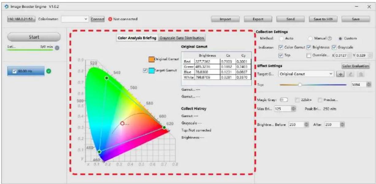
Click the "Send" button to send the settings to the hardware.

Save the "Save to HW" button to save the settings to the hardware.

Click the "Save" button to save the current parameter settings to the software.

To set the gamut of the displayed image to the specified gamut:
Switch "Target Gamut" under "Effect Settings".


To save the settings, click the "Save to HW" button and save the setting to the hardware.

To set any gamut:
Click the "+" button next to "Target Gamut" under "Effect Settings".

The setting screen opens.

Enter a gamut name.
Select the parameter in "Baseline Gamut".
Set any values.
Click the "OK" button to save the settings.

To set the gamut of the displayed image to the gamut that has been added:
Switch "Target Gamut" under "Effect Settings".

Changes in the values under "Effect Settings" are reflected immediately after the operation to the screen displayed on the LED display.

The settings of each series are as follows.
| LD-Q2 LD-E1 LD-FA2/ | FE2 LD-FE3/FH3 LD-FA3 LD-D1/D2 | ||||
| Image booster Not Applicable Default ON | |||||
| .vglcx file attached No Yes | |||||
| 18 bit+ Default OFF | |||||
| 22 bit+ No Yes | |||||
| Magic gray No Default ON | |||||
NOTE: Some models may not be available in some countries.
Screen Control (test pattern display)
(1) Log in with the administrator privileges (English-60).
(2) Click "Screen Control".
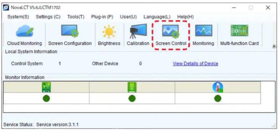
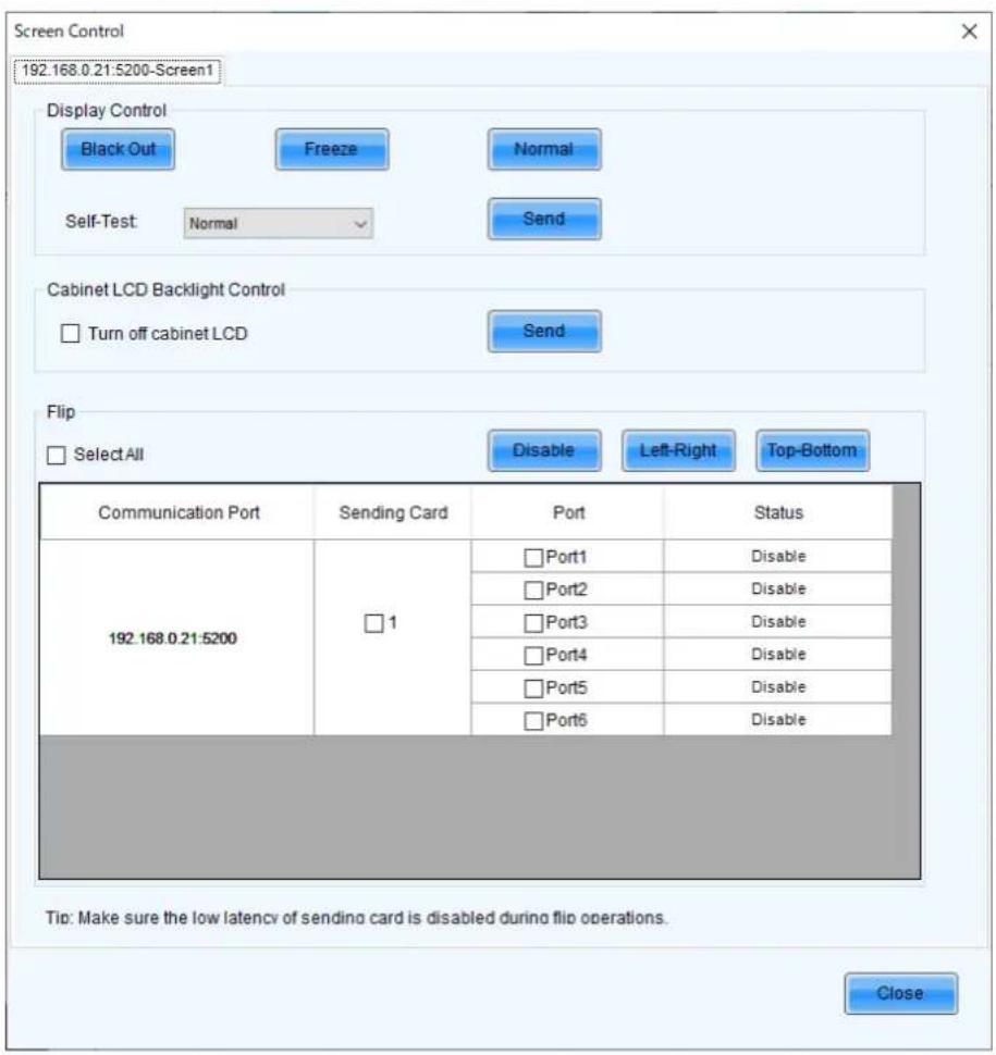
Select any test pattern under "Self-Test" to display it.

3. State monitoring using the software
In case of a problem, you will be able to determine the location where it occurred by monitoring the state of the system.
3-1 How to determine the state of the system
The state displayed in NovaLCT changes as follows.
(1) The control system is not connected.

If the connection is not established after a while, click "System(S)" - "Reconnect(R)".

(2) The control system is connected but the state is not determined.

After a while, the normal state is displayed if the system is in the normal state. If there is a problem, one indicator (●) will be red.
Normal state

Preliminary confirmation
Confirm in advance that the control system is correctly recognized.
Click the "Screen Configuration" button.

Select the communication port to which the system you want to check is connected.

The Screen Configuration window opens.

Select the "Screen Connection" tab.

Click the "Read from HW" button.

Check that the settings are correct.

3-2 Display under normal conditions
The display is green under normal conditions.


![COMB Screen Time (s) Alquiring the Current Monitoring Data / [100%] Unconditional Information Current Temperature(℃): 33 Kibetar Temperature(℃): 55 Average Temperature(℃): 34 Quantity of cooling cell with low-temperature 1. Fast Forward Temperature: Quick cooling cell with temperature: 0 Screen Name…](/content/2026/08/1614070/images/f3abf6cee2816512f7769909c2ed576a49028124655a99def5590af6fc5e9892.jpg)
State of the LED controller State of the LED modules Temperature of the LED modules
3-3 Monitoring condition settings
Click the "Configuration" button on the "MonitorSite" screen.

Description of the setting items
Refresh Period: Period of monitoring item checks
Set Rereading Times: Number of checks when an error occurs
Send E-mail when same fault: Number of errors at which to send an e-mail.
Monitoring is executed after each set period.
The number of checks when an error is detected.
Set whether or not to send an e-mail when the same error is detected multiple times during checks at the end of the monitoring period.
Click the "Refresh Period" button to set the refresh period.
Click the "Save" button to save the setting.

To receive information on the state of LED modules by e-mail, click the "Email" button and set the conditions to send e-mails.

Click the "^" icon in the taskbar, place the cursor on the Mars Server Provider icon, right-click, and then select "Detect Config".

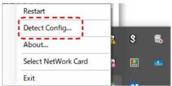
Clear the "Auto detect controller" checkbox.
(Note that the checkbox is checked by default.)

3-4 Display under abnormal conditions
(1) Problem with the input signal to the LED controller

To display more details, click "Monitoring", and then click "Sending card" on the screen that is displayed.

(2) Problem with the LED modules

To display more details, click "Monitoring", and then click "Receiving card" on the screen that is displayed.

In the example shown on the left, the following problems must be considered.
- Signal loss between the screen of the 3rd row 3rd column and the screen of the 2nd row 3rd column
→ Check the internal LAN cable. - Problem with both power units of the screen of the 2nd row 3rd column
→ Check the rear indicator (red) to see if it is lit.

There is no problem if it is lit red.
If it is not lit, the power unit is probably broken. (Replacing the power unit)
- Problem with the receiving card of the screen of the 2nd row 3rd column
→ Check that the receiving card is securely connected. If there are no connection problems, the receiving card may malfunction. (Replacing the receiving card)
(3) Problem with the internal temperature of the LED modules

To display more details, click "Monitoring", and then click "Temperature" on the screen that is displayed.

(4) Communication problem

1. Updating the LED controller hardware program
Prepare the LED controller hardware program used for the update.
(1) Click on the NovaLCT window and enter "admin".

(2) Click the "Refresh" button and check the version of the controller hardware program.

(3) Click the "Browse" button.
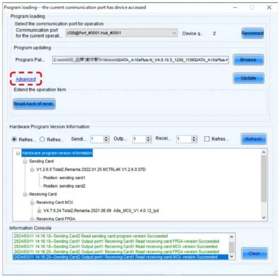
(4) Select the hardware program you have prepared for the update.
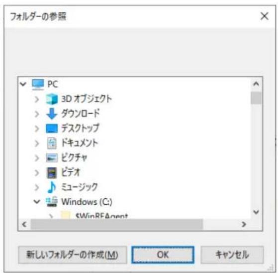
(7) Check that all files are selected.
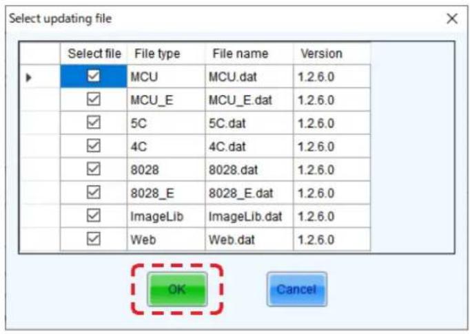
(8) Click the "Update" button.

(9) Click the "OK" button.

2. Saving the calibration data of the receiving card as a file
(1) Select "Calibration".

(2) Select "Manage Coefficients".

(3) Select "Save calibration coefficients to database".

(4) Select "Save to a New Database".

(5) Select "Cabinet-Database".

(6) Click the "Create" button.
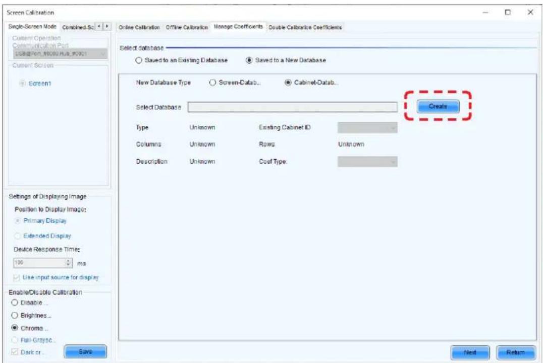
(7) Choose any name and select any location to create the database to save the receiving card calibration data.
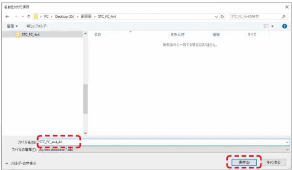
(9) Check that "Select by Topology or List" is selected.
Select the module that uses the receiving card for which you want to save the calibration data.

(10) The color of the selected module changes to yellow. Click the "Save" button.

(11) Set any Cabinet ID for the calibration data that will be saved.

(12) Click the "OK" button.

(13) Check the message and click the "OK" button.

(14) Click the "Return" button.

(15) Check that the file has been saved.

3. Writing the calibration data sto the receiving card
3-1 Writing the calibration data saved in a file to the receiving card
(1) Select "Calibration".

(2) Select "Manage Coefficients".

(3) Select "Set coefficients for a new receiving card".

(4) Check that "Select by Topology or List" is selected.
Select the module that uses the receiving card to which you want to write the calibration data.

(5) The color of the selected module changes to yellow. Click the "Next" button.

(6) Click the "Browse" button.
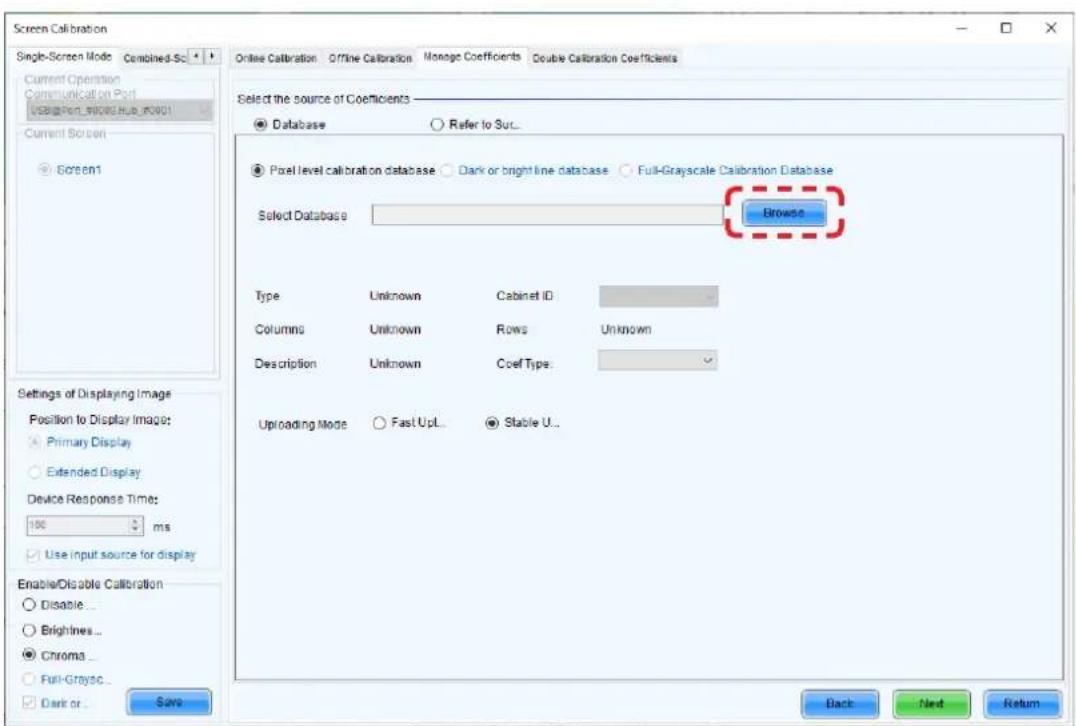
(7) Select the target file and click the "Open" button.

(9) Check the message and click the "OK" button.

(10) The white test pattern is displayed on the specified screen.
You may exit the test pattern using the “esc” key. (The test pattern can also be displayed using the display control of the controller.)
Adjust the brightness and colors as required.
Click the "Next" button.
(11) Click the "Save" button.
(12) Check the message and click the "OK" button.

(13) Click the "Finish" button.
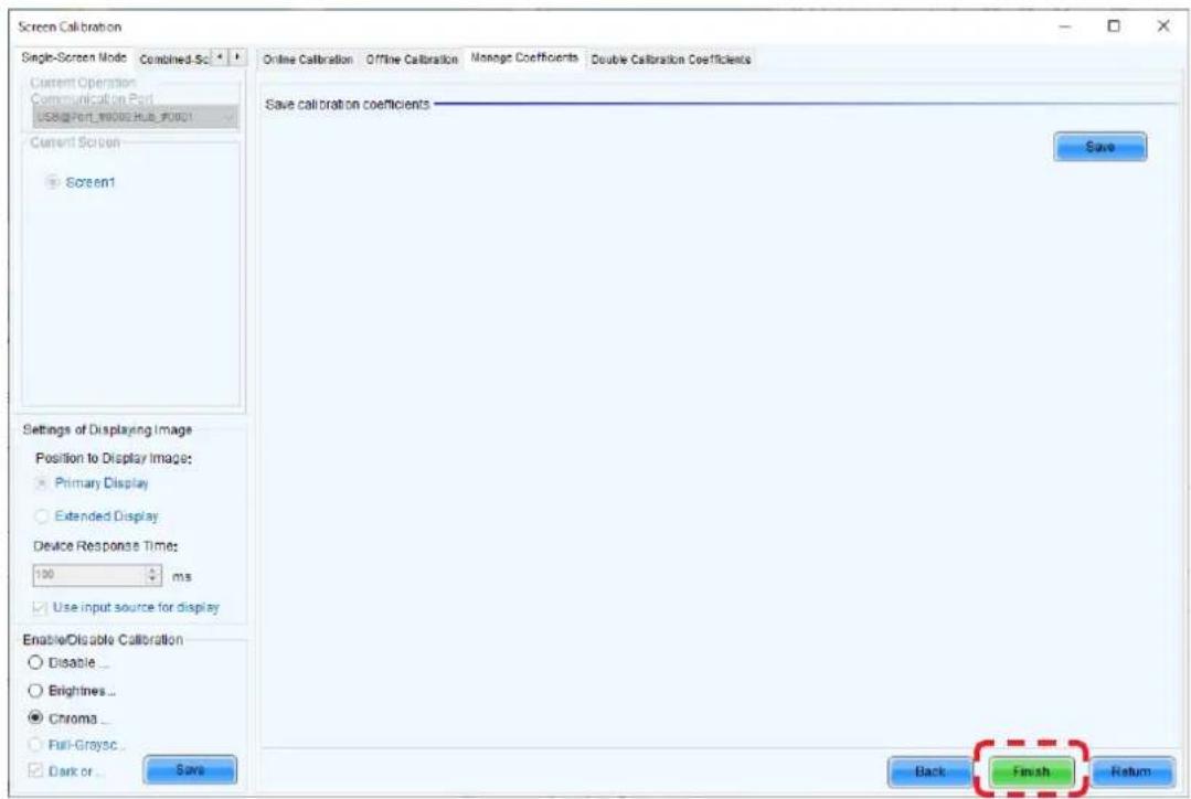
(14) Perform the "4. Writing the calibration data from the receiving card to the pixel card" (English-154) procedure.
3-2 Writing the calibration data stored in the supplied USB memory key to the receiving card
Click the "Calibration" button.
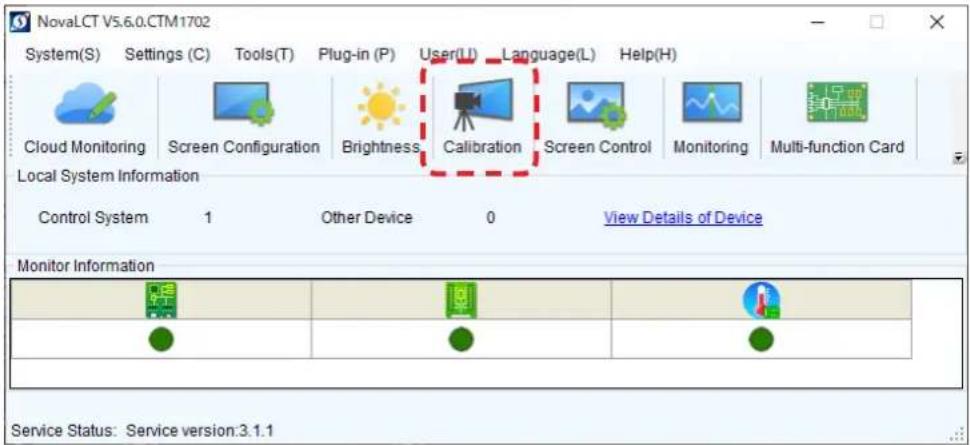
Select the "Manage Coefficients" tab.

Click the "Upload coefficients" button.

Select the database type.
The database type to select varies depending on the writing target. Select the type according to the information in the table below.
For models with two calibration modes, make the setting for "Low gray" first.
Check the calibration mode for each model, and then select the database corresponding to the calibration mode.
Calibration mode of each model
| LD-Q2 LD-E1 LD-FA2/FE2 | LD-FE3/FH3 LD-FA3 | LD-D1/D2 | |||||
| Pitch All All | All All All | 0.9 mm | 1.2 / 1.5 mm | ||||
| Calibration method | Screen calibration | ||||||
| Calibration mode | Low gray Low gray Low gray | ||||||
| Chroma | Brightness and Chroma | Full gray | Brightness and Chroma | Brightness and Chroma | |||
NOTE: Some models may not be available in some countries.
Correspondence between database and calibration modes
| Select database Calibration mode | |
| Pixel level calibration database | |
| Normal coef Chroma / Brightness and Chroma | |
| Low-gray scale coef Low gray | |
| Full Gray scale Calibration database Full gray | |
| Dark and bright line database | - (Calibration mode independent) |
Click the "Browse" button.

Select the *.db file that contains the calibration data.
Example for Low gray:
The procedure is the same for Chroma / Brightness and Chroma.

The database is set.
For Pixel level calibration, select the parameter in "Coef Type" under "Description". In the case of Low gray, select "Low-Grayscale Coef".
In the case of Chroma / Brightness and Chroma, select "Normal Coef". Click the "Next" button to go to the target selection.

Example for Full gray:

The database is set.
Click the "Next" button to go to the target selection.

Example for Chroma:

Example for Brightness and Chroma:

The database is set.
Click the "Next" button to go to the target selection.

Target selection
The target selection screen is displayed.
The procedure is explained taking Chroma / Brightness and Chroma as an example.
The selection procedure varies depending on the calibration data that is uploaded.
Here, explanations are given when selecting "Topology".
With Topology, the receiving card is selected individually (single LED module).

Click the upload target to select it.
The selected location is displayed yellow after the selection.
Click the "Next" button.

Click the "Upload" button.

Display during the upload.

Click the "OK" button.

Check the state of the image at the upload location.
If calibration has been performed correctly, click the "Save" button to save the settings.
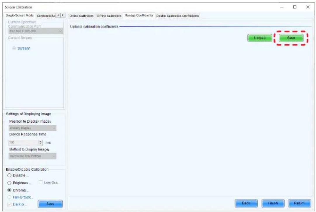
Display during the save process.

Click the "OK" button.

The data is written to the receiving card (not to the pixel card).
To write the data to the pixel card, execute the procedure in "4. Writing the calibration data from the receiving card to the pixel card" (English-154).
Click the "Finish" button.
Click the "Return" button to upload another file.

4. Writing the calibration data from the receiving card to the pixel card
The following assumes that the image is displayed with the calibration data saved in the receiving card.
(1) Select "Calibration".

(2) Click on the NovaLCT window and enter "admin".

(3) The "Save Calibration Coefficients to Module" button is displayed. Select "Select by Topology".

(4) Select any save target.

(5) The color of the selected module changes to yellow. Click the "Save Calibration Coefficients to Module" button.

(6) Check the message and click the "OK" button.

(7) Click the "Save to HW" button.

(8) Click the "Return" button.

5. Updating the hardware program
Prepare the receiving card hardware program (DATA_*) that will be written to the receiving card. The firmware installed on the receiving card at the factory is stored in the USB memory that comes with the product.
(1) Start NovaLCT and log in with the administrator privileges (English-60).
(2) Click on the NovaLCT window and enter "admin".
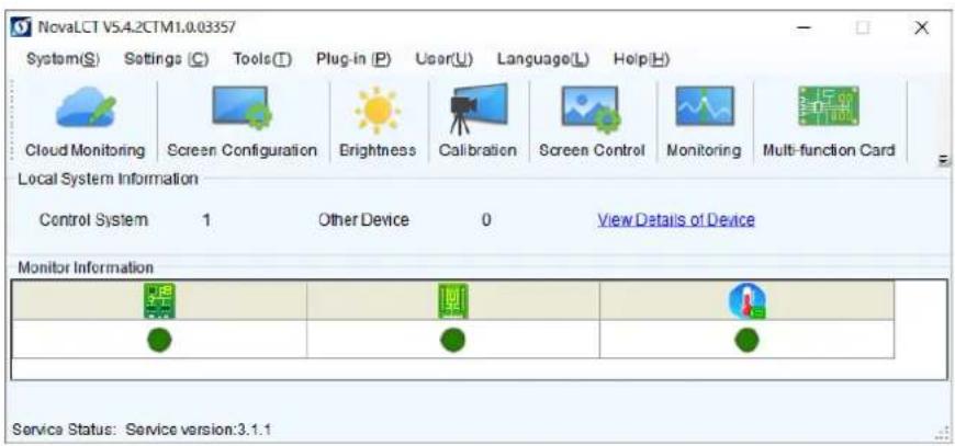
(3) Select (a) and then click "Refresh" (b).

(4) The connection is established if a screen similar to the following is displayed.

(5) Click "Browse" (c).

(6) Select the folder that contains the hardware program (for the receiving card) you want to write and click "OK".
(7) The selected file is displayed in the field (d) below.

(8) Click "Advanced" (e).
A screen similar to the following is displayed. Check all files and click "OK".
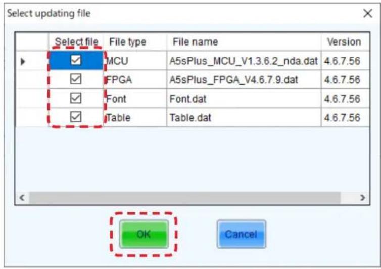
(9) Click "Update" (f).
A screen similar to the following is displayed. Select the receiving card to which to write the hardware program.
To update all receiving cards, select "All receiving cards" (g) and click "OK".
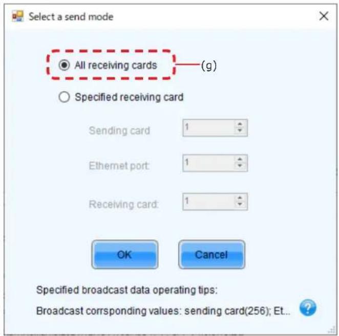
(10) The hardware program update is complete.
Click "Refresh" (b) and check that the version has been updated to the update version.

6. Saving the configuration data
(1) Select "Screen Configuration".
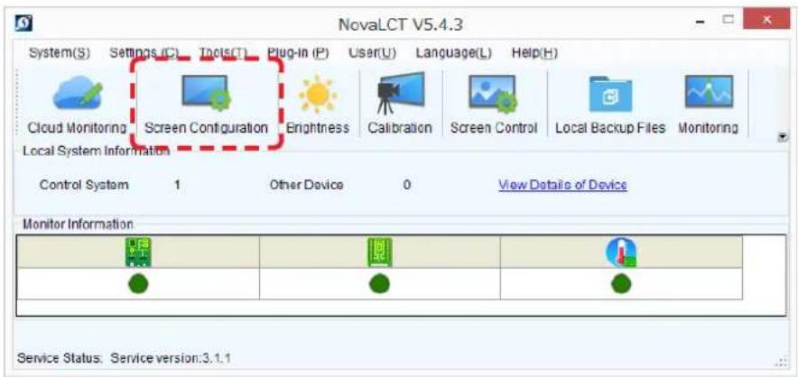
(2) Click the "Next" button.

(3) Click the "Read from Receiving Card" button.

(4) Set the "Sending Card", "Port Number", and "Receiving Card" values according to the position of the receiving card from which to read the data. Click the "OK" button.

(5) Check the message and click the "OK" button.

(6) Click the "Save to File" button.
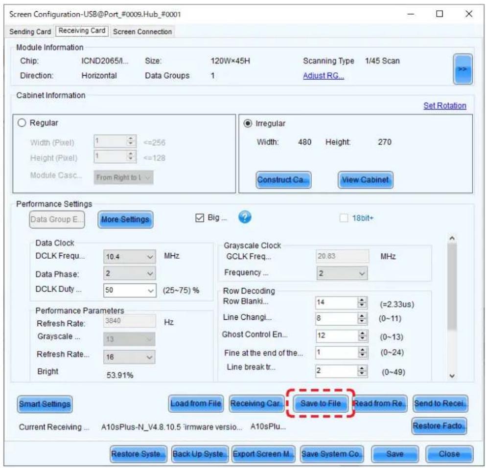
(7) Choose any name and save the file.

7. Updating the configuration data
Prepare the configuration file (*.rcfgx) that will be written to the receiving card.
The configuration file (*.rcfgx) installed on the receiving card at the factory is stored in the USB memory that comes with the product.
(1) Start NovaLCT and log in with the administrator privileges (English-60).
(2) Click "Screen Configuration" (a).
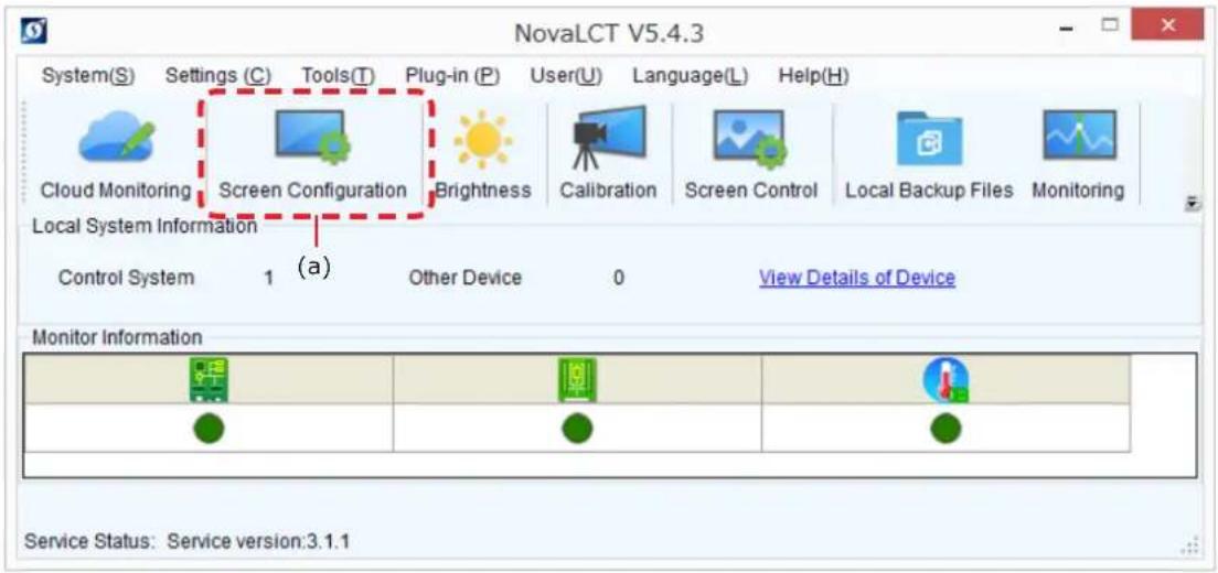
(3) Click "Next" (b).

(b)
(4) On the Screen Configuration screen that is displayed, select the "Receiving Card" tab (c).

(5) Click "Load from File" (d).
Select the configuration file (rcfgx file) you want to write to the receiving card.
A screen similar to the following is displayed when the reading process is complete. Click "OK".
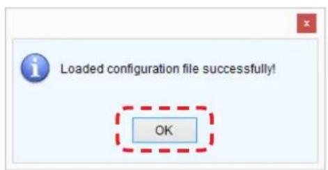
(6) Click "Send to Receiving Card" (e).
A screen similar to the following is displayed. Select the receiving card to which you want to write the configuration file.
(Select "All Receiving Cards" if only the receiving card to which you want to write the data is connected.)
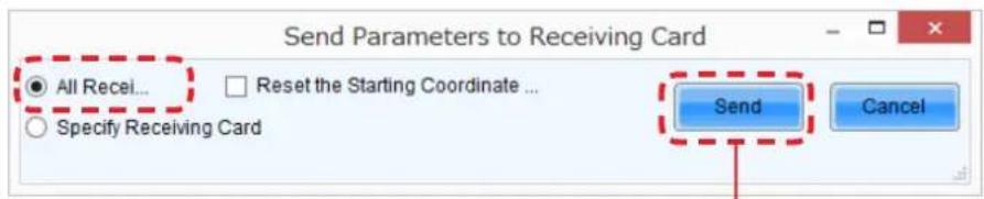
(f)
(7) After selecting the receiving card, click "Send" (f).
Click "Save" (g).
8. Redundancy setting method
8.1 Configuring the settings with two LED controllers connected to the PC using LAN cables
Connect the LED controllers and the LED modules with LAN cables.
Terminate the Backup system connection at the RJ-45 connector located top left on the last module in the daisy chain connection.
With the FA series
![graph TD A["HUB"] --> B["LED controllers Main (Primary)"] B --> C["Backup"] D["LED modules"] --> E["LED module"] style A fill:#f9f,stroke:#333 style B fill:#ccf,stroke:#333 style C fill:#cfc,stroke:#333 style D fill:#fcc,stroke:#333 style E fill:#ffc,stroke:#333](/content/2026/08/1614070/images/812fb895b9765f60df5e0d1eb56e0c7983fb49acee540b7bc5bf906671a068ba.jpg)
* For the MCTRL 4K LED controller, the way to make connections is similar to this example.
With the FE series
![graph TD A["Laptop"] --> B["HUB"] B --> C["LED controllers Main (Primary)"] C --> D["Backup"] D --> E["LED modules"] style A fill:#f9f,stroke:#333 style B fill:#ccf,stroke:#333 style C fill:#cfc,stroke:#333 style D fill:#fcc,stroke:#333 style E fill:#ffc,stroke:#333](/content/2026/08/1614070/images/42a07fe3fd781263d66107929b01eb9813f476cfba75ea4752525ab3d7428f0e.jpg)
* For the MCTRL 4K LED controller, the way to make connections is similar to this example.
Start the control software NovaLCT and log in with the administrator privileges (English-60). Click "Screen Configuration".

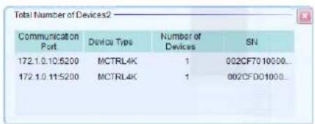
Check the port in "Select Communication Port", select the Main (Primary) and Backup system LED controllers by their IP address, and then click "Next".
Configure the settings for the Main (Primary) controller and Backup controller separately.

Main (Primary) Backup

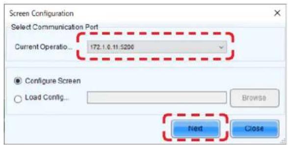
On the Main (Primary) side
Click the "Restore Factory Settings" button for initialization.
After initialization, configure the settings for "Select Input Source" and "Source Configuration".
If the factory setting is correctly configured and the device connection is the same as when the factory setting was configured, check the settings without performing initialization.

Main (Primary)
Select the Screen Connection tab.
Select/enter the value for "Screen Type", "Receiving Card Size", "Columns" and "Rows", and use "Ethernet Port No." and the screen configuration section to configure the connection.
* For details of the configuration procedure, refer to the User's Manual.
Only with the FE series
Next, select the Sending Card tab.
Go to "Redundancy", select the checkbox for "Set as Primary" and click "Save".


On the Backup side
Click the "Restore Factory Settings" button for initialization.
After initialization, configure the settings for "Select Input Source" and "Source Configuration".
If the factory setting is correctly configured and the device connection is the same as when the factory setting was configured, check the settings without performing initialization.

Backup
Select the Screen Connection tab.
Configure the connection in the same way as for Main (Primary).
* The direction of connection is the same as for Main (Primary).
Only with the FE series
Next, select the Sending Card tab.
Go to "Redundancy", select the checkbox for "Set as Backup" and click "Save".


Only with the FA series
Select "Tool" - "More" - "Screen Backup Settings".
The "Screen Backup Settings" screen is displayed.
Click "Add" and add the settings.


Set any screen name and set "Primary Screen" and "Backup Screen".
The entry is added to the Screen Backup Settings list.

Check the current brightness setting.
Click the "Brightness" button.
In the Brightness Adjustment screen, set the desired brightness value and click the "Save to HW" button.

![Brightness Adjustment 172.1.0.10 [500-Screen] 172.1.0.11.6200=Serosal Brightness Brightness < > 127 (49.8%) Gray-scale Contrast Advanced Settings Gamma ... Color Te... Color Spa... Gamma ● Gamma Value... < > 2.8 ○ Custom _ Configuration Refresh Save to HW](/content/2026/08/1614070/images/7298f6d2954e58f730fa30a18da11e647fd901bbefae4a99257033e4d014565b.jpg)
![Brightness Adjustment 172. 1. 0. 10: 5200-Screen [172. 1. 0. 11: 5200-Screen] Brightness Manual Adjustment Auto Adjustment Brightness < > 127 (49.8%) Gray-scale Contrast Advanced Settings Gamma... Color Te... Color Spa... Gamma ● Gamma Valu... < > > 2.8 ○ Custom... Configuration Refresh Save to HW](/content/2026/08/1614070/images/b924a439ca83df27a432a1ece55df20b803d1d4ef97877043a75f3c4fa72ae5d.jpg)
The monitoring screens appear like below.
With the FA series

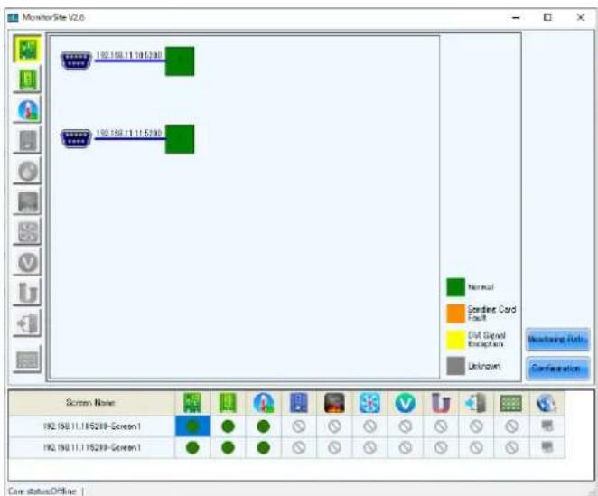


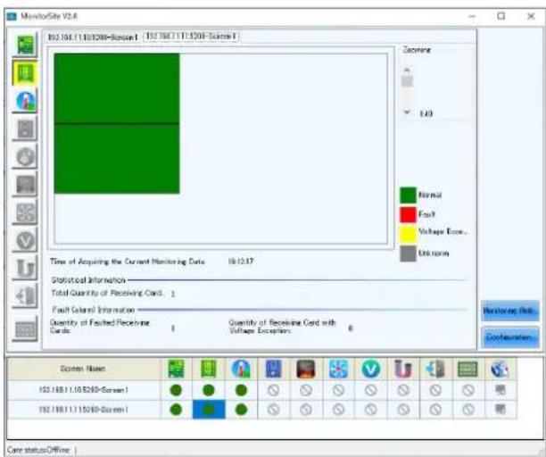

With the FE series
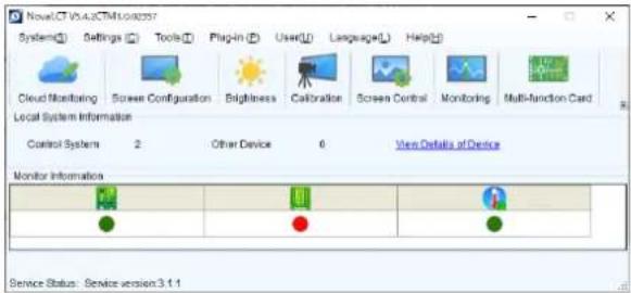


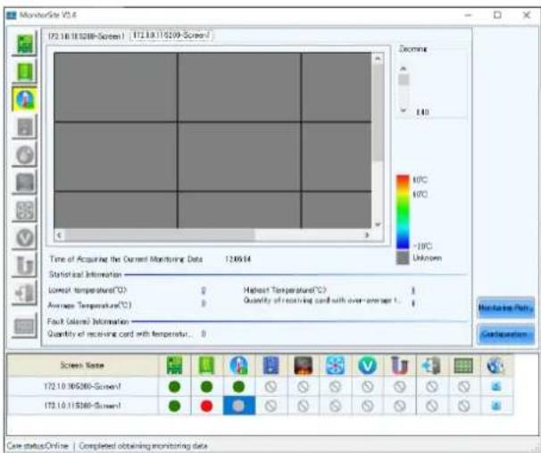
Only with the FE series
Note: On the monitoring screen, the LED modules configured as "Backup" are displayed in red color (this is not an indication of a fault).
If a fault occurs on modules configured as "Main (Primary)", "Backup" modules are displayed in green color, which is an indication of normal state.
"Main (Primary)" modules are operating normally
Main (Primary) Backup
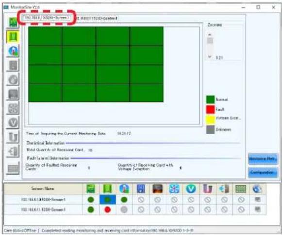

Modules connected to port 1 are operating as "Backup".
Main (Primary) Backup


In the start-up screen of NovaLCT, the status indicator circle for "Monitor Information" receiving card becomes red in color.

In the case of MCTRL 4K, the display of the LED controllers is as follows.
(This example display is for the case of connection using four Ethernet cables.)
With the FA series
Upper: Main (Primary)
Lower: Backup

With the FE series
Upper: Backup
Lower: Main (Primary)

Only with the FA series
While referring to "Saving the calibration data of the receiving card as a file" and "Writing the calibration data saved in a file to the receiving card", write the calibration data to the receiving card on the backup side.
8.2 Configuring the settings with two LED controllers connected to the PC using USB cables
Connect the LED controllers and the LED modules with LAN cables.
Terminate the Backup system connection at the RJ-45 connector located top left on the last module in the daisy chain connection.
With the FA series
![graph TD A["Laptop"] --> B["LED controllers Main (Primary)"] B --> C["Device 1"] C --> D["LED modules"] D --> E["Backup"] E --> F["LED modules"] style A fill:#f9f,stroke:#333 style B fill:#ccf,stroke:#333 style C fill:#cfc,stroke:#333 style D fill:#fcc,stroke:#333 style E fill:#cff,stroke:#333 style…](/content/2026/08/1614070/images/73a832c2b04f91b73fb163d5153a959490065e327596448f42ea9372d5039c2c.jpg)
* For the MCTRL 4K LED controller, the way to make connections is similar to this example.
With the FE series
![graph TD A["Laptop"] --> B["LED controllers Main (Primary)"] B --> C["Backup"] C --> D["LED modules"] D --> E["Output 1"] D --> F["Output 2"] D --> G["Output 3"]](/content/2026/08/1614070/images/2734c5128f0593430da524baf8a4ba969fd604fc003c3ab5a75a7ef037b1d64a.jpg)
* For the MCTRL 4K LED controller, the way to make connections is similar to this example.
Start the control software NovaLCT and log in with the administrator privileges (English-60). Click "Screen Configuration".

This is the screen configuration method when you want to write the calibration data to the backup side with the FA series.
Select the port in "Select Communication Port", and then click "Next".

In the Screen Configuration screen that is displayed, select the "Sending Card" tab.

Click the "Restore Factory Settings" button for initialization.
After initialization, configure the settings for "Select Input Source" and "Source Configuration".
If the factory setting is correctly configured and the device connection is the same as when the factory setting was configured, check the settings without performing initialization.

Select the Screen Connection tab.
Select/enter the value for "Screen Type", "Receiving Card Size", "Columns" and "Rows", and use "Ethernet Port No." and the screen configuration section to configure the connection.
* For details of the configuration procedure, refer to the User's Manual.

Notes on the setting operation (FA Series):
Set "Quantity of Screens" to "2" and click the "Configure" button.
Configure the settings for both the sending card 1 and sending card 2.
When the settings configuration is complete, click the "Send to HW" button.
Notes on the setting operation (FE Series):
Make sure that the value of "Quantity of Screens" is 1.
(To change a different value to 1, click the Configur" button.)
It is not necessary to configure the settings for Sending Card 2.
When the settings configuration is complete, click the "Send to HW" button.
Only with the FE series
Select the Sending Card tab and click "Add". The Redundancy Settings screen is displayed.


In the Redundancy Settings screen, set the Port number of the Backup side LED controller (Sending Card) that matches the Port number of the Primary side LED controller (Sending Card). After entering the value, click the "Add" button.
In the LED configuration example (English-179), the settings are as follows.
| Serial Number of Primary Sending Card : 1 |
| Serial Number of Primary Port : 1 |
| Serial Number of Backup Sending Card : 2 |
| Serial Number of Backup Port : 1 |
| Serial Number of Primary Sending Card : 1 |
| Serial Number of Primary Port : 2 |
| Serial Number of Backup Sending Card : 2 |
| Serial Number of Backup Port : 2 |
| Serial Number of Primary Sending Card : 1 |
| Serial Number of Primary Port : 3 |
| Serial Number of Backup Sending Card : 2 |
| Serial Number of Backup Port : 3 |
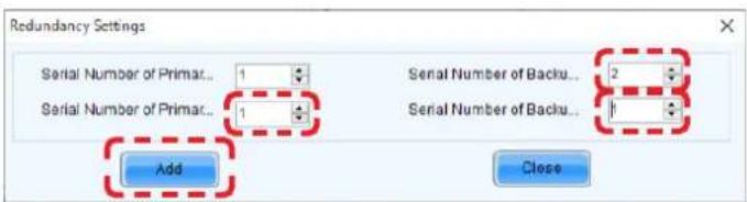
When the settings configuration is complete, the Sending Card tab appears like below.
Click the "Send" button.
Click the "Save" button.

Only with the FA series
Select "Tool" - "More" - "Screen Backup Settings".
The "Screen Backup Settings" screen is displayed.
Click "Add" and add the settings.


Set any screen name and set "Primary Screen" and "Backup Screen".
The entry is added to the Screen Backup Settings list.


Check the current brightness setting.
Click the "Brightness" button.
In the Brightness Adjustment screen, set the desired brightness value and click the "Save to HW" button.
With the FA series


With the FE series


The monitoring screens appear like below.
With the FA series


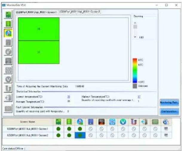
With the FE series


In the case of MCTRL 4K, the display of the LED controllers is as follows.
With the FA series
(This example display is for the case of connection using one Ethernet cable.)
Upper: Main (Primary)
Lower: Backup

With the FE series
(This example display is for the case of connection using four Ethernet cables.)
Upper: Backup
Lower: Main (Primary)

8.3 Configuring the settings with one LED controller connected to the PC using a LAN cable
Connect the LED controllers and the LED modules with LAN cables.
With the FA series
For the backup system connection, make the connection to the RJ-45 connector on the right side of the module on the lowest row the same way as with the main system connection.

* For the MCTRL 4K LED controller, the way to make connections is similar to this example. Use the same method also when connecting the PC with a USB cable.
With the FE series
Terminate the Backup system connection at the RJ-45 connector located top left on the last module in the daisy chain connection.
![graph TD A["Laptop"] --> B["LED controllers"] B --> C["LED modules"] C --> D["Grid of 10x10 modules with green arrows indicating direction"] style A fill:#f9f,stroke:#333 style B fill:#ccf,stroke:#333 style C fill:#cfc,stroke:#333 style D fill:#fcc,stroke:#333](/content/2026/08/1614070/images/7a41fd4ac262e373833c805799b8148c8c3596eb83c0c0847ff8eb1d7bfa5f1e.jpg)
* For the MCTRL 4K LED controller, the way to make connections is similar to this example. Use the same method also when connecting the PC with a USB cable.
Start the control software NovaLCT and log in with the administrator privileges (English-60). Click "Screen Configuration".

Select the port in "Select Communication Port", and then click "Next".

Click the "Restore Factory Settings" button for initialization.
After initialization, configure the settings for "Select Input Source" and "Source Configuration".
If the factory setting is correctly configured and the device connection is the same as when the factory setting was configured, check the settings without performing initialization.

Select the Screen Connection tab.
Select/enter the value for "Screen Type", "Receiving Card Size", "Columns" and "Rows", and use "Ethernet Port No." and the screen configuration section to configure the connection.
* For details of the configuration procedure, refer to the User's Manual.

Notes on the setting operation (FA Series):
Set "Quantity of Screens" to "2" and click the "Configure" button.
Configure the settings for both the sending card 1 and sending card 2.
When the settings configuration is complete, click the "Send to HW" button.
Notes on the setting operation (FE Series):
Make sure that the value of "Quantity of Screens" is 1.
(To change a different value to 1, click the Configur" button.)
It is not necessary to configure the settings for Sending Card 2.
When the settings configuration is complete, click the "Send to HW" button.
Only with the FE series
Select the Sending Card tab and click "Add". The Redundancy Settings screen is displayed.


In the Redundancy Settings screen, set the Port to use on the LED controller.
In the LED configuration example (English-190), the settings are as follows. After entering the value, click the "Add" button.
Serial Number of Primary Sending Card : 1 Serial Number of Primary Port : 1 Serial Number of Backup Sending Card : 1 Serial Number of Backup Port : 4
Serial Number of Primary Sending Card : 1 Serial Number of Primary Port : 2 Serial Number of Backup Sending Card : 1 Serial Number of Backup Port : 5
Serial Number of Primary Sending Card : 1 Serial Number of Primary Port : 3 Serial Number of Backup Sending Card : 1 Serial Number of Backup Port : 6

When the settings configuration is complete, the Sending Card tab appears like below.
Click the "Send" button.
Click the "Save" button.

Only with the FA series
Select "Tool" - "More" - "Screen Backup Settings".
The "Screen Backup Settings" screen is displayed Click "Add" and add the settings.
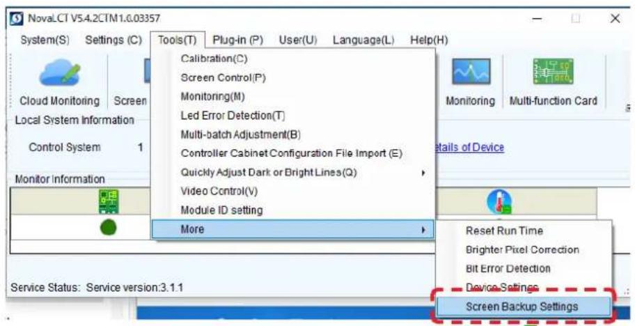


Set any screen name and set "Primary Screen" and "Backup Screen".
The entry is added to the Screen Backup Settings list.


Check the current brightness setting.
Click the "Brightness" button.
In the Brightness Adjustment screen, set the desired brightness value and click the "Save to HW" button.
With the FA series
Configure both the main and backup sides.

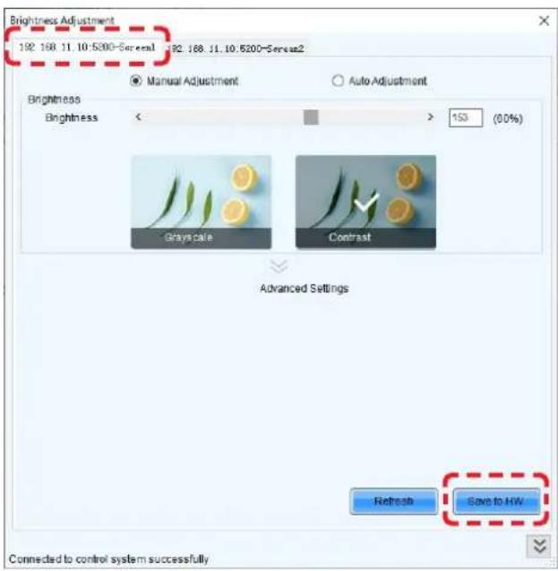
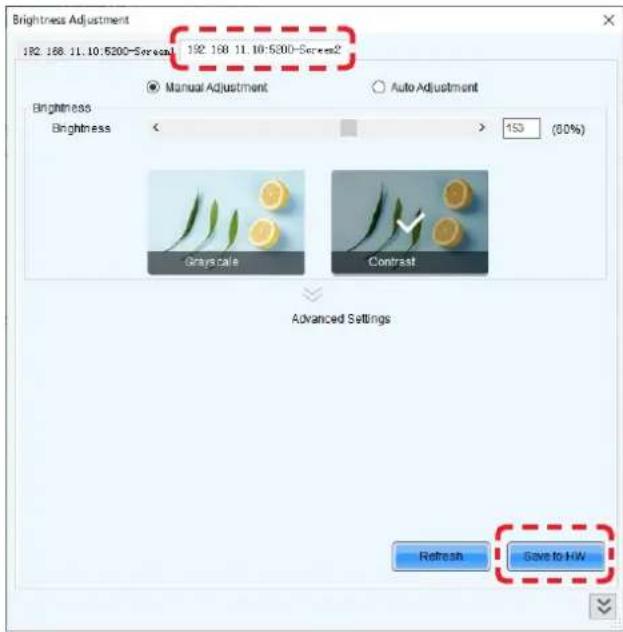
With the FE series

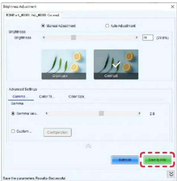
The monitoring screens appear like below.
With the FA series


With the FE series

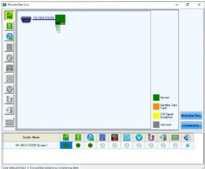


In the case of MCTRL 4K, the display of the LED controllers is as follows.
(This example display is for the case of connection using one Ethernet cable.)
With the FA series
Port1: Main (Primary)
Port2: Backup

With the FE series
Port1: Main (Primary)
Port2: Backup
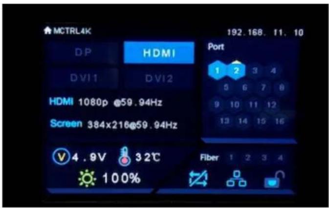
Only with the FA series
Calibration method for "8.2 Configuring the settings with two LED controllers connected to the PC using USB cables" and "8.3 Configuring the settings with one LED controller connected to the PC using a LAN cable"
After performing "Update the Calibration Data" (English-67) for the receiving card on the Main side, write the pixel card calibration data to the receiving card on the Backup side.
Display the "Send by Topology" screen while referring to "Update the Calibration Data" (English-67).
(1) The "Send by Topology" screen is displayed.
Move the cursor above the screen and enter "BACKUP".
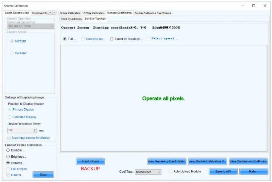
(2) The "Read Coefs to Backup Rv Card" button is displayed. Click the "Read Coefs to Backup Rv Card" button.

(3) A message is displayed when the process is complete. Click the "OK" button. Click the "Return" button to return to the "Manage Coefficients" screen.

(4) The "Manage Coefficients" screen is displayed. Select "Screen2" under "Current Screen". Then, click "Module Flash".

(5) The "Send by Topology" screen is displayed. Click the "Save Calibration Coefficients to Receiving Card" button.

(6) A message is displayed when the process is complete. Click the "OK" button to complete the procedure.

Saved calibration coefficients to receiving card successfully.
Specifications (FA series)
Models for indoor use
| LD-FA122 LD | -FA152 LD-FA1 | 92 LD-FA252 LD | -FA312 LD-FA382 | ||||
| LED configuration 3in1 SMD | |||||||
| Pixel pitch 1.27 mm 1.58 mm 1.90 mm 2.53 mm | 3.17 mm 3.80 mm | ||||||
| Number of displayed pixels (resolution/module) | 480×270 38 | 4×216 320×180 | 240×135 192 | ×108 160×90 | |||
| Brightness 800 cd/m | 2 | 1200 cd/m2 | |||||
| Contrast ratio 5000:1 7000:1 | |||||||
| Brightness adjustment range 0 to 100% (256 increments) | |||||||
| Gamma correction 1.0 to 4.0 (default setting: 2.8) | |||||||
| Color temperature 3000 K to 9500 K (default setting: 6500 K) | |||||||
| Viewing angle Up 85°, Down 85°, Left 85°, Right 85° Up 70°, Down 70°, Left 80°, Right 80° | |||||||
| Signal interface S | signal input | 2×RJ-45 | |||||
| Signal output | 2×RJ-45 | ||||||
| Power supply | 100 V AC to 240 V AC, 50 Hz/60 Hz | ||||||
| Power consumption (all white, 100% brightness) | 125 W | 120 W | |||||
| IP rating | Front IP20 / Rear IP20 | ||||||
| Maintenance | Front | ||||||
| Dimensions | 608×342×49 mm | ||||||
| Weight | 8.8 kg | ||||||
| Operating environment | Temperature | -20 to 40°C | |||||
| Humidity | 10% to 80% (without condensation) | ||||||
| Altitude | No more than 5000 m | ||||||
| Storage environment | Temperature | -20 to 45°C | |||||
| Humidity | 10% to 85% (without condensation) | ||||||
Specifications are subject to change without notice.
Models for indoor use
| LD-FA092 | ||
| LED configuration 4in1 SMD (IMD) | ||
| Pixel pitch 0.95 mm | ||
| Number of displayed pixels (resolution/module) | 640×360 | |
| Brightness 600 cd/m | 2 | |
| Contrast ratio 5000:1 | ||
| Brightness adjustment range 0 to 100% (256 increments) | ||
| Gamma correction 1.0 to 4.0 (default setting: 2.8) | ||
| Color temperature 3000 K to 9500 K (default setting: 6500 K) | ||
| Viewing angle Up 70°, Down 70°, Left 70°, Right 70° | ||
| Signal interface Signal input 2×RJ-45 | ||
| Signal output 2×RJ-45 | ||
| Power supply 100 V AC to 240 V AC, 50 Hz/60 Hz | ||
| Power consumption (all white, 100% brightness) | 150 W | |
| IP rating Front IP20 / Rear IP20 | ||
| Maintenance Front | ||
| Dimensions 608×342×49 mm | ||
| Weight | 8.8 kg | |
| Operating environment | Temperature | -20 to 40°C |
| Humidity | 10% to 80% (without condensation) | |
| Altitude | No more than 5000 m | |
| Storage environment | Temperature | -20 to 45°C |
| Humidity | 10% to 85% (without condensation) | |
Specifications are subject to change without notice.
| Module configuration LD-FA122 | 4×4 | LD-FA1525×5 | LD-FA0926×6 | LD-FA1926×6 | |
| LED configuration 3in1 SMD 4in1 SMD (IMD) 3in1 SMD | |||||
| Pixel pitch 1.27 mm 1.58 mm 0.95 mm 1.90 mm | |||||
| Number of displayed pixels (resolution/module) | 1920×1080 1920×1080 3840×2160 1920×1080 | ||||
| Brightness 800 cd/m | 2 | 600 cd/m2 | 800 cd/m2 | ||
| Contrast ratio 5000:1 | |||||
| Brightness adjustment range 0 to 100% (256 increments) | |||||
| Gamma correction 1.0 to 4.0 (default setting: 2.8) | |||||
| Color temperature 3000 K to 9500 K (default setting: 6500 K) | |||||
| Viewing angle Up 85°, Down 85°, Left 85°, Right 85° Up 70°, Down 70°, | Left 70°, Right 70° | Up 85°, Down 85°, Left 85°, Right 85° | |||
| Signal interface Signal input | 2×RJ-45 | ||||
| Signal output | 2×RJ-45 | ||||
| Power supply | 100 V AC to 240 V AC, 50 Hz/60 Hz | ||||
| Power consumption (all white, 100% brightness) | 2000 W | 3125 W | 5400 W | 4500 W | |
| IP rating | Front IP20 / Rear IP20 | ||||
| Maintenance | Front | ||||
| Dimensions | 2444×1475.5×78 mm | 3052×1817.5×78 mm | 3660×2159.5×78 mm | 3660×2159.5×78 mm | |
| Weight | 182 kg | 279 kg | 390.8 kg | 390.8 kg | |
| Operating environment | Temperature | -20 to 40°C | |||
| Humidity | 10% to 80% (without condensation) | ||||
| Altitude | No more than 5000 m | ||||
| Storage environment | Temperature | -20 to 45°C | |||
| Humidity | 10% to 85% (without condensation) | ||||
Specifications are subject to change without notice.
| Module configuration LD-FA122 | 8×8 | LD-FA2528×8 | |
| LED configuration 3in1 SMD | |||
| Pixel pitch 1.27 mm 2.53 mm | |||
| Number of displayed pixels (resolution/module) | 3840×2160 1920×1080 | ||
| Brightness 800 cd/m | 2 | 1200 cd/m2 | |
| Contrast ratio 5000:1 7000:1 | |||
| Brightness adjustment range 0 to | 100% (256 increments) | ||
| Gamma correction 1.0 to 4.0 (default setting: 2.8) | |||
| Color temperature 3000 K to 9500 | K (default setting: 6500 K) | ||
| Viewing angle Up 85°, Down 85°, | Left 85°,Right 85° | Up 70°, Down 70°, Left 80°,Right 80° | |
| Signal interface Signal input 2×RJ-45 | |||
| Signal output 2×RJ-45 | |||
| Power supply | 100 V AC to 240 V AC, 50 Hz/60 Hz | ||
| Power consumption (all white, 100% brightness) | 8000 W | 7680 W | |
| IP rating | Front IP20 / Rear IP20 | ||
| Maintenance | Front | ||
| Dimensions | 4876×2843.5×78 mm | 4876×2843.5×78 mm | |
| Weight | 659.2 kg 659.2 kg | ||
| Operating environment | Temperature | -20 to 40°C | |
| Humidity 10% to 80% (without condensation) | |||
| Altitude | No more than 5000 m | ||
| Storage environment | Temperature | -20 to 45°C | |
| Humidity 10% to 85% (without condensation) | |||
Specifications are subject to change without notice.
Specifications (FE series)
Models for indoor use
| LD-FE122 LD | -FE152 LD-FE1 | 92 LD-FE252 LD | -FE312 LD-FE3 | 82 | |||
| LED configuration 3in1 SMD | |||||||
| Pixel pitch 1.27 mm 1.58 mm 1.90 mm 2.53 mm | 3.17 mm 3.80 mm | ||||||
| Number of displayed pixels (resolution/module) | 480×270 38 | 4×216 320×180 | 240×135 192 | ×108 160×90 | |||
| Brightness 700 cd/m | 2 | 1000 cd/m2 | |||||
| Contrast ratio 4000:1 5000:1 | |||||||
| Brightness adjustment range 0 to 100% (256 increments) | |||||||
| Gamma correction 1.0 to 4.0 (default setting: 2.8) | |||||||
| Color temperature 3000 K to 9500 K (default setting: 6500 K) | |||||||
| Viewing angle Up 80°, Down 80°, Left 80°, Right 80° Up 70°, Down 70°, Left 80°, Right 80° | |||||||
| Signal interface S | signal input | 1×RJ-45 | |||||
| Signal output | 1×RJ-45 | ||||||
| Power supply | 100 V AC to 240 V AC, 50 Hz/60 Hz | ||||||
| Power consumption (all white, 100% brightness) | 125 W | 120 W | |||||
| IP rating | Front IP20 / Rear IP20 | ||||||
| Maintenance | Front | ||||||
| Dimensions | 608×342×49 mm | ||||||
| Weight | 8.8 kg | ||||||
| Operating environment | Temperature | -20 to 40°C | |||||
| Humidity | 10% to 80% (without condensation) | ||||||
| Altitude | No more than 5000 m | ||||||
| Storage environment | Temperature | -20 to 45°C | |||||
| Humidity | 10% to 85% (without condensation) | ||||||
Specifications are subject to change without notice.
Models for indoor use
| LD-FE092 | ||
| LED configuration 4in1 SMD (IMD) | ||
| Pixel pitch 0.95 mm | ||
| Number of displayed pixels (resolution/module) | 640×360 | |
| Brightness 600 cd/m | 2 | |
| Contrast ratio 5000:1 | ||
| Brightness adjustment range 0 to 100% (256 increments) | ||
| Gamma correction 1.0 to 4.0 (default setting: 2.8) | ||
| Color temperature 3000 K to 9500 K (default setting: 6500 K) | ||
| Viewing angle Up 70°, Down 70°, Left 70°, Right 70° | ||
| Signal interface Signal input 1×RJ-45 | ||
| Signal output 1×RJ-45 | ||
| Power supply 100 V AC to 240 V AC, 50 Hz/60 Hz | ||
| Power consumption (all white, 100% brightness) | 150 W | |
| IP rating Front IP20 / Rear IP20 | ||
| Maintenance Front | ||
| Dimensions 608×342×49 mm | ||
| Weight | 8.8 kg | |
| Operating environment | Temperature | -20 to 40°C |
| Humidity | 10% to 80% (without condensation) | |
| Altitude | No more than 5000 m | |
| Storage environment | Temperature | -20 to 45°C |
| Humidity | 10% to 85% (without condensation) | |
Specifications are subject to change without notice.
| Module configuration LD-FE122 | 4×4 | LD-FE1525×5 | LD-FE0926×6 | LD-FE1926×6 | |
| LED configuration 3in1 SMD 4in1 SMD (IMD) 3in1 SMD | |||||
| Pixel pitch 1.27 mm 1.58 mm 0.95 mm 1.90 mm | |||||
| Number of displayed pixels (resolution/module) | 1920 × 1080 1920 × 1080 3840 × 2160 | 1920 × 1080 | |||
| Brightness 700 cd/m | 2 | 600 cd/m2 | 700 cd/m2 | ||
| Contrast ratio 4000:1 5000:1 4000:1 | |||||
| Brightness adjustment range 0 to 100% (256 increments) | |||||
| Gamma correction 1.0 to 4.0 (default setting: 2.8) | |||||
| Color temperature 3000 K to 9500 K (default setting: 6500 K) | |||||
| Viewing angle | Up 80°, Down 80°, Left 80°, Right 80° | Up 70°, Down 70°, Left 70°, Right 70° | Up 80°, Down 80°, Left 80°, Right 80° | ||
| Signal interface | Signal input | 1×RJ-45 | |||
| Signal output | 1×RJ-45 | ||||
| Power supply | 100 V AC to 240 V AC, 50 Hz/60 Hz | ||||
| Power consumption (all white, 100% brightness) | 2000 W | 3125 W | 5400 W | 4500 W | |
| IP rating | Front IP20 / Rear IP20 | ||||
| Maintenance | Front | ||||
| Dimensions | 2444×1475.5×78 mm | 3052×1817.5×78 mm | 3660×2159.5×78 mm | 3660×2159.5×78 mm | |
| Weight | 182 kg | 279 kg | 390.8 kg | 390.8 kg | |
| Operating environment | Temperature | -20 to 40°C | |||
| Humidity | 10% to 80% (without condensation) | ||||
| Altitude | No more than 5000 m | ||||
| Storage environment | Temperature | -20 to 45°C | |||
| Humidity | 10% to 85% (without condensation) | ||||
Specifications are subject to change without notice.
| Module configuration LD-FE122 | 8×8 | LD-FE2528×8 | |
| LED configuration 3in1 SMD | |||
| Pixel pitch 1.27 mm 2.53 mm | |||
| Number of displayed pixels (resolution/module) | 3840 × 2160 1920 × 1080 | ||
| Brightness 700 cd/m | 2 | 1000 cd/m2 | |
| Contrast ratio 4000:1 5000:1 | |||
| Brightness adjustment range 0 to 100% (256 increments) | |||
| Gamma correction 1.0 to 4.0 (default setting: 2.8) | |||
| Color temperature 3000 K to 9500 K (default setting: 6500 K) | |||
| Viewing angle Up 80°, Down 80°, Left 80°, Right 80° | Up 70°, Down 70°, Left 80°, Right 80° | ||
| Signal interface Signal input 1×RJ-45 | |||
| Signal output 1×RJ-45 | |||
| Power supply 100 V AC to 240 V AC, 50 Hz/60 Hz | |||
| Power consumption (all white, 100% brightness) | 8000 W | 7680 W | |
| IP rating | Front IP20 / Rear IP20 | ||
| Maintenance | Front | ||
| Dimensions | 4876×2843.5×78 mm | 4876×2843.5×78 mm | |
| Weight | 659.2 kg 659.2 kg | ||
| Operating environment | Temperature | -20 to 40°C | |
| Humidity | 10% to 80% (without condensation) | ||
| Altitude | No more than 5000 m | ||
| Storage environment | Temperature | -20 to 45°C | |
| Humidity | 10% to 85% (without condensation) | ||
Specifications are subject to change without notice.
LD-FA092, LD-FA122, LD-FA152, LD-FA192, LD-FA312, LD-FA382 LD-FE092, LD-FE122, LD-FE152, LD-FE192, LD-FE312, LD-FE382


Rear

(Unit: mm)
LD-FA252, LD-FE252

Rear

(Unit: mm)
Adjustment plate

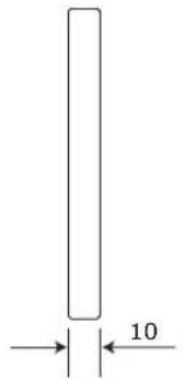
(Unit: mm)
- INSTALLATION AND MAINTENANCE MANUAL
- SAFETY PRECAUTIONS AND MAINTENANCE
- ABOUT THE SYMBOLS
- WARNING
- CAUTION
- RECOMMENDED USE & MAINTENANCE
- ABOUT THE LED LAMPS
- LAMP BREAK-IN
- ABOUT THE PIXEL CARD
- WHEN USING OTHER THAN THE TOP (TYPE A)
- WHEN USED AT THE TOP (TYPE B)
- WHEN CONNECTING A LAN CABLE FROM THE MIDDLE (TYPE A')
- SET NAME LIST
- INSTALLATION LOCATION
- HANDLE
- MARK THE POSITIONS OF THE ANCHOR POINTS ON THE WALL
- MAKE THE HOLES AT THE ANCHOR POSITIONS
- PREPARING MOUNTING BAR
- ATTACHING MOUNTING BAR CONNECTOR
- REMOVING MOUNTING BAR CONNECTOR
- INSTALL THE MOUNTING BARS
- INSTALL THE POWER BAR
- HOW TO REMOVE THE POWER BAR COVER
- INSTALL THE CABINET HANGER PINS TO THE BACK OF THE CABINETS
- INSTALL THE CABINETS
- HOW TO CONNECT THE POWER CORD (FA SERIES)
- HOW TO CONNECT THE POWER CORD (FE SERIES)
- ASSEMBLY DIAGRAMS
- INSTALLATION WITHOUT A FRAME SET
- WIRING
- MAXIMUM NUMBER OF SIGNAL CONNECTIONS
- MAXIMUM NUMBER OF POWER CONNECTIONS
- CONNECTION WHEN USING A WALL-MOUNT FRAME
- FA SERIES
- FE SERIES
- BACKSIDE HOLE CABINET
- CABLES FOR BACKSIDE HOLE CABINET
- [INFO] FOR FIXING THE CABLE
- PRECAUTIONS ON USE OF THE POWER CONNECTOR (WAGO)
- INSTALLATION PRECAUTIONS
- HOW TO CONNECT THE POWER CORD
- POWER CODE CONNECTION CHECKING
- LAN CABLE CONNECTION
- INSTALLING THE PIXEL CARD
- PREPARING FOR USING NOVALCT SOFTWARE
- ENTER THE SCREEN CONFIGURATION MENU
- MODULE CONNECTION SETTINGS
- CONFIGURE THE CONNECTION
- RECEIVING CARD SETTINGS
- UPDATE THE CALIBRATION DATA
- CLICK ON "MODULE FLASH
- CLICK THE "VIEW MODULE CALIBRATION COEFFICIENTS" BUTTON
- MODULE SETTING METHOD WHEN PERFORMING MODULE FLASH FOR INDIVIDUAL MODULES
- SELECT "SELECT BY TOPOLOGY OR LIST
- SELECT THE TARGET MODULE. CLICK INSIDE THE FRAME OF THE TARGET MODULE
- WHAT CAN BE DONE WITH AUTO UPLOAD MODULE
- PRECAUTIONS RELATED TO THE OPERATION (ADJUSTING THE COLORS ON A PART OF THE SCREEN)
- NOTE
- DETAILED PROCEDURE
- SELECT THE "MANAGE COEFFICIENTS" TAB
- SELECT "MODULE FLASH
- CHECK THE "AUTO UPLOAD MODULE" BOX
- CLICK THE "SAVE TO HW" BUTTON
- CLICK THE "RETURN" BUTTON TO RETURN TO THE PREVIOUS SCREEN
- LINE CALIBRATION
- LD-FA252, LD-FE
- CLEANING METHOD
- REMOVING A PIXEL CARD
- REMOVING AND INSTALLING THE HUB BOARD
- INSTALLING THE HUB BOARD
- REPLACING THE POWER UNIT
- REPLACING THE RECEIVING CARD
- CHECK THE HARDWARE PROGRAM
- UPDATE THE CONFIGURATION DATA
- ADJUST THE BRIGHTNESS, COLOR TEMPERATURE, AND GAMMA
- REPLACE THE LED CONTROLLER
- REPLACE THE CONTROL PC
- ADJUSTING THE COLORS ON A PART OF THE SCREEN
- SELECT BY TOPOLOGY OR LIST: ADJUST MULTIPLE MODULES
- IMAGE BOOSTER ENGINE
- SCREEN CONTROL (TEST PATTERN DISPLAY)
- STATE MONITORING USING THE SOFTWARE
- HOW TO DETERMINE THE STATE OF THE SYSTEM
- PRELIMINARY CONFIRMATION
- DISPLAY UNDER NORMAL CONDITIONS
- MONITORING CONDITION SETTINGS
- DISPLAY UNDER ABNORMAL CONDITIONS
- PROBLEM WITH THE INPUT SIGNAL TO THE LED CONTROLLER
- PROBLEM WITH THE INTERNAL TEMPERATURE OF THE LED MODULES
- UPDATING THE LED CONTROLLER HARDWARE PROGRAM
- CLICK THE "BROWSE" BUTTON
- SELECT THE HARDWARE PROGRAM YOU HAVE PREPARED FOR THE UPDATE
- CHECK THAT ALL FILES ARE SELECTED
- CLICK THE "UPDATE" BUTTON
- CLICK THE "OK" BUTTON
- SAVING THE CALIBRATION DATA OF THE RECEIVING CARD AS A FILE
- SELECT "CALIBRATION
- SELECT "MANAGE COEFFICIENTS
- SELECT "SAVE CALIBRATION COEFFICIENTS TO DATABASE
- SELECT "SAVE TO A NEW DATABASE
- WRITING THE CALIBRATION DATA STO THE RECEIVING CARD
- WRITING THE CALIBRATION DATA SAVED IN A FILE TO THE RECEIVING CARD
- WRITING THE CALIBRATION DATA STORED IN THE SUPPLIED USB MEMORY KEY TO THE RECEIVING CARD
- EXAMPLE FOR LOW GRAY
- EXAMPLE FOR BRIGHTNESS AND CHROMA
- TARGET SELECTION
- WRITING THE CALIBRATION DATA FROM THE RECEIVING CARD TO THE PIXEL CARD
- CLICK ON THE NOVALCT WINDOW AND ENTER "ADMIN
- CLICK THE "RETURN" BUTTON
- UPDATING THE HARDWARE PROGRAM
- CLICK "UPDATE" (F)
- THE HARDWARE PROGRAM UPDATE IS COMPLETE
- SAVING THE CONFIGURATION DATA
- UPDATING THE CONFIGURATION DATA
- REDUNDANCY SETTING METHOD
- CONFIGURING THE SETTINGS WITH TWO LED CONTROLLERS CONNECTED TO THE PC USING LAN CABLES
- ON THE MAIN (PRIMARY) SIDE
- ONLY WITH THE FE SERIES
- ON THE BACKUP SIDE
- ONLY WITH THE FA SERIES
- WITH THE FA SERIES
- WITH THE FE SERIES
- CONFIGURING THE SETTINGS WITH TWO LED CONTROLLERS CONNECTED TO THE PC USING USB CABLES
- CONFIGURING THE SETTINGS WITH ONE LED CONTROLLER CONNECTED TO THE PC USING A LAN CABLE
- CALIBRATION METHOD FOR "8.2 CONFIGURING THE SETTINGS WITH TWO LED CONTROLLERS CONNECTED TO THE PC USING USB CABLES" AND "8.3 CONFIGURING THE SETTINGS WITH ONE LED CONTROLLER CONNECTED TO THE PC USING A LAN CABLE
- SPECIFICATIONS (FA SERIES)
- SPECIFICATIONS (FE SERIES)
Brand : SHARP
Model : LD-FE312
Category : Monitor