
Expert 41864 - Multimeter Draper - Free user manual and instructions
Find the device manual for free Expert 41864 Draper in PDF.


| Product Type | Digital Multimeter |
| Brand | Draper Expert |
| Model | 41864 |
| Dimensions (approx.) | 150 x 70 x 30mm |
| Weight (approx.) | 200g |
| Power Supply | 1 x 9V battery (6F22) |
| AC Voltage Range | 0-600V |
| DC Voltage Range | 0-600V |
| AC/DC Current Range | 0-10A |
| Resistance Range | 0-20MΩ |
| Continuity Test | Yes, with buzzer |
| Diode Test | Yes |
| Data Hold | Yes |
| Backlight Display | Yes |
| Safety Rating | CAT II 600V |
| Maintenance & Cleaning | Clean casing with dry cloth; replace battery when low battery indicator appears. |
| Spare Parts & Repairability | Replaceable battery, fuse and standard test leads. |
| General Information | Designed for professional use, reliable and user-friendly. |
Frequently Asked Questions - Expert 41864 Draper
User questions about Expert 41864 Draper
0 question about this device. Answer the ones you know or ask your own.
Ask a new question about this device
Download the instructions for your Multimeter in PDF format for free! Find your manual Expert 41864 - Draper and take your electronic device back in hand. On this page are published all the documents necessary for the use of your device. Expert 41864 by Draper.
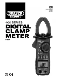
USER MANUAL Expert 41864 Draper
EN
Original Instructions
Version 3
June 2024
400 SERIES
DIGITAL CLAMP METER
41864

1. Preface
1.1 Product Reference
User Manual for: 400 Series Digital Clamp Meter
Stock No: 41864
Part No: DCM400
Read this manual in full before using this product and retain it for future use. Always use the latest version of the manual. Please visit drapertools.com/manuals for the latest version.
1.2 Revisions
Version 1: March 2017
First release
Version 2: June 2017
Version 3: June 2024
2. Contents
-
Preface 2
-
Contents 2
-
Product Introduction 2-3
-
Health and Safety Information 4
-
Identification and Unpacking 5
-
Operating Instructions 6-7
-
Maintenance and Disposal 8
-
Warranty 8
-
Explanation of Symbols 9
3. Product Introduction
3.1 Intended Use
This meter is designed to measure voltage, current and resistance across AC and DC circuits. Fitted with a large LCD backlit display screen and work light.
Any other application beyond the conditions established for use will be considered misuse. Draper Tools accepts no responsibility for improper use of this product.
Part of our core range, this product is suitable for regular use by enthusiasts and tradespersons alike.
3.2 Specification
Stock No. 41864
Part No. DCM400
Jaw Opening Max. Size: 36mm (approx)
Battery Type: 3 x 1.5V AAA (not supplied)
Meter Rating; CAT III 600V
Overload Protection: 600V DC or AC (RMS).
Weight: 333g (including battery)
Dimensions: 208 X 79 X 36mm
Operating Conditions
Operating Temperature: 5 - 35°C
Storage Temperature: -10 - 50°C
DC Voltage
| Range Accuracy Resolution | ||
| 200mV | ±0.8% reading + 2 digits | 0.1mV |
| 2V 1mV | ||
| 20V 10mV | ||
| 200V 0.1V | ||
| 600V ±1% reading + 2 digits 1V | ||
Input impedance: 10MΩ.
Max. input voltage: 600V DC or AC (RMS).
AC Voltage
| Range Accuracy Resolution | ||
| 200mV | ±1% reading + 10 digits | 0.1mV |
| 2V 1mV | ||
| 20V 10mV | ||
| 200V 0.1V | ||
| 600V ±1.2% reading + 10 digits 1V | ||
Input Impedance: 10MΩ.
Measuring frequency range: 40Hz\~400Hz.
Maximum Input Voltage: 600V DC or AC (RMS).
AC Current
| Range Accuracy Resolution | ||
| 2A ±3.5% reading + 10 digits 0.001A | ||
| 20A ±3% reading + 10 digits 0.01A | ||
| 200A | ±2.5% reading + 10 digits 0.1A | |
| 600A | ±1.5% reading + 5 digits 1A | |
Maximum input current: 600A AC.
Frequency range: 50Hz.
Resistance
| Range Accuracy Resolution | ||
| 200Ω | ±1.2% reading + 2 digits | 0.1Ω |
| 2kΩ 0.001kΩ | ||
| 20kΩ 0.01kΩ | ||
| 200kΩ | 0.1kΩ | |
| 2MΩ | 0.001MΩ | |
| 20MΩ | ±2% reading + 5 digits 0.01MΩ | |
Overload protection: 600V DC or AC (RMS).
Diode
| Range | Accuracy | Resolution |
| Displays the forward pressure drop approximation (Open circuit voltage of about 1.5V) | 1mV |
Overload protection: 250V DC or AC (RMS).
Continuity Test
| Range | Accuracy | Resolution |
| The buzzer will sound when about ≤60Ω (open circuit voltage of about 0.45V) | 100mΩ |
Note: The buzzer may sound between 60Ω and 120Ω.
The buzzer does not sound when it is greater than 120Ω.
Overload protection: 250V DC or AC (RMS).
4. Health and Safety Information
Important: Read all the Health and Safety instructions before attempting to use this product. Failure to read these instructions may result in serious injury or death.

WARNING! Contact with live circuits can result in severe electrical shock. When measuring voltage above 30V, current above 10mA or AC power with an inductive load, take care not to touch the exposed contacts as they may give a serious electric shock.
- DO NOT measure voltages above 600V DC or AC (RMS).
- DO NOT apply voltages to the probes whilst measuring current, diodes, continuity or capacitors.
- Discharge all high-voltage capacitors before measuring capacitance.
- DO NOT clamp both the live and neutral wires at the same time during the measurement.
-
Remove the test leads from the meter when measuring using the clamp.
-
ONLY trained and competent personnel may operate this device.
- Use this product ONLY as instructed in this manual.
- Use ONLY accessories and spare parts supplied by Draper Tools.
- DO NOT use any other leads with this product than those supplied. Contact Draper Tools for replacement options if the leads become damaged.
- If the battery must be replaced, use one with the same specification.
- Observe all standard precautions and good practice when working with live electrical currents.
- Inspect the product for damage before every use, particularly the contact tips.
- DO NOT use this product if the device or probe leads are damaged in any way or if there is evidence of battery leakage.
- If battery acid comes into contact with your skin, wash it off immediately with plenty of clean water.
-
If battery acid comes into contact with your eyes, flush them with plenty of clean water and seek immediate medical attention.
-
Ensure that the device is clean, dry and free from grease before use.
-
Ensure that the function dial is in the correct position before taking a measurement.
-
DO NOT use this product if it exhibits abnormal behaviour and have it checked by a qualified and authorised technician before next use.
- DO NOT exceed the maximum rated capacity per function for this device as it may expose you to a shock hazard.
- Ensure that the probe contacts are disconnected from the load or test circuit before moving the function dial.
- Assess any specific additional risks to the operator before each use.
- DO NOT expose this product to excessive ambient temperature, high humidity, flammable substances or environments that produce a strong magnetic field.
- DO NOT use this product around explosive gases, vapours or dust.
- DO NOT immerse this device in water or expose it to wet conditions.
- ALWAYS wear protective insulated gloves while using this product.
- Keep your fingers behind the guards on the probes and clamp during use.
- ALWAYS remove the contact leads from the device before removing the battery cover or opening the back panel.
- DO NOT operate this device with the rear housing open or missing and DO NOT use it if the rear housing cannot be closed properly.
- NEVER insert the probe contacts into the device sockets.
• DO NOT abuse, mutilate or burn the battery. - Ensure the battery is fitted in the correct +/- orientation.
- Remove the batteries when the product is stored for extended periods.
- DO NOT attempt to repair this device; it contains no user-serviceable parts.
- Keep this product out of reach of children.

WARNING! ALWAYS ensure that the operator is not in contact with the ground while taking measurements, using insulating materials to prevent the current from earthing.
5. Identification and Unpacking
5.1 Product Overview

(1) Measurement clamp head.
(2) Inspection light.
(3) Protection guard.
(4) Clamp trigger.
(5) Measuring function selection dial.
(6) Back light & work light.
(7) Function buttons.
(8) Display.
(9) Probe sockets.
(9a) (COM) Common earth probe
(9b) INPUT
(10) Current direction marking.
5.2 LCD Display

(11) Battery low indicator.
(12) Automatic range indicator.
(13) Diode checking indicator.
(14) Continuity checking indicator.
(15) Maximum measurement indicator.
(16) Data hold indicator.
(17) DC Signal measurement indicator.
(18) Negative polarity indicator.
(19) AC Signal indicator.
(20) Unit indicator.
5.2 What's in the Box?
Carefully remove the product from the packaging and examine it for any signs of damage that may have occurred during shipment.
Before assembling the product, lay the contents out and check them against the parts listed below. If any part is damaged or missing, do not attempt to use the product. Please contact the Draper Helpline; contact details can be found at the back of this manual.

A. Storage case.
B. Test probe
C. Test probe caps
5.3 Packaging
Keep the product packaging for the duration of the warranty period in case the product needs to be returned for repair.

WARNING! Keep packaging materials out of reach of children. Dispose of packaging correctly and responsibly and in accordance with local regulations.
Important: Before operating this product, read and understand all the safety instructions listed in this manual.
6.1 Back Light and Work Light Button
Press and hold the ' *button to switch the back light/work light on or off.
- The lights will automatically turn off after about 15 seconds.
Note: The inspection light will only come on while in AC current function.
6.2 Function Switch Button (SEL)
The 'SEL' button is for switching between DCV/ACV, and between diode and continuity measuring.
6.3 MAX Readings Button
Press the 'MAX' button to display the maximum value of measurement data on the display.
6.4 Auto/Manual Switch Button (RAN)
- Press the 'RAN' button to switch between AUTO and manual range mode. The default mode is AUTO.
- To switch back to AUTO mode press and hold the button for more than 2 seconds.
6.5 AC Current Measurement using Current Clamp Head

WARNING! Risk of electric shock. DO NOT measure current using the probes. Remove the test leads from the meter when measuring with the clamp head.
- Rotate the measurement function selection dial to the appropriate current.
- Press the trigger to open the clamp, pass the wire to be measured into the centre of the clamp, and then slowly release the trigger until the clamp is fully closed.
- Read the measurement result from the display.
Note: The meter can only measure one current conductor at a time.
6.6 DC Voltage Measurement
- Rotate the measurement function selection dial to the DC voltage position.
- Connect the black lead to the COM probe socket (9a) and the red lead to the INPUT probe socket (9b).
- The measured value is read from the display. The polarity display will indicate the polarity of the socket to which the red test lead is connected.
6.7 AC Voltage Measurement
- Rotate the measurement function selection dial to the AC voltage position.
- Connect the black lead to the COM probe socket (9a) and the red lead to the INPUT probe socket (9b).
- The measured value is read from the display.
6.8 Resistance measurement

WARNING! Risk of electric shock. When measuring the impedance on the line, make sure that the circuit power is off and the capacitors on the circuit are fully discharged.
- Rotate the measurement function selection dial to the resistance ( Ω ) position and ensure that the power to the circuit under test is off.
- Press the 'SEL' button to select the resistance ( Ω ) measurement function.
- Connect the black lead to the COM probe socket (9a) and the red lead to the INPUT probe socket (9b).
- The measured value is read from the display.
Note: When there is no input (e.g. open circuit), the display will show 'OL' indicating that the measured value is out of range. If the measured resistance is greater than 1MΩ, it may take a few seconds for the meter to stabilize the reading. This is normal for high impedance measurements.
6.9 Continuity/Diode Test

WARNING! Risk of electric shock. Make sure the circuit power is off, and the circuit capacitors are completely discharged.
6.10 Holding Reading
- Press the 'HOLD' button to hold the reading while taking a measurement, the value and 'H' will be held on the display.
- Press the 'HOLD' button again to return to the normal reading function.
7. Maintenance 8. Warranty
Important: Disconnect the probes from the sockets and any other source of voltage before performing any maintenance on this product.
- Replace the probes IMMEDIATELY if they are damaged in any way or the conductors are exposed; contact Draper Tools for replacement options.
Important: Replacement probes must be rated CAT III 20A.
7.1 Replacement Battery

WARNING! To avoid false readings that may result in electric shock or personal injury, replace the battery as soon as the ' symbol appears on the meter display. To avoid electrical shock or personal injury, turn off the meter and ensure that the test lead has been disconnected from the measuring circuit before opening the battery cover and replacing it with a new one.
Follow these steps to replace the battery:
- Turn off the meter.
- Remove all test leads from the probe sockets.
- Unscrew the battery compartment cover and remove.
- Disconnect and remove the old batteries.
- Replace with three new AAA batteries, pay attention to the battery positive and negative. Do not mix new with old batteries and do not use re-chargeable batteries.
- Refit the battery cover and tighten the screws.
7.2 Disposal
At the end of its working life, dispose of the product responsibly and in line with local regulations. Recycle where possible.
- DO NOT dispose of this product with domestic waste; most local authorities provide appropriate recycling facilities.
- DO NOT burn or mutilate batteries; this may release toxic or corrosive substances.


Warranty period is 12 months from date of purchase. Visit drapertools.com/warranty for more information.
9. Explanation of Symbols


Read the instruction manual

Fuse

WEEE- Waste Electrical & Electronic Equipment Do not dispose of Waste Electrical & Electronic Equipment in with domestic rubbish

Danger! High voltage/current

For indoor use only; do not expose to rain

Voltage AC

Class II construction (Double insulated)

Voltage DC

European conformity

Current AC

UK Conformity Assessed

Current DC

Diode test

Resistance in Ohms

Temperature

Warning!
Contact Details
Draper Tools
Draper Tools Limited
Hursley Road
Chandler's Ford
Eastleigh
Hampshire
S053 1YF
UK
Website: drapertools.com
Email: sales@drapertools.com
Product Helpline: +44 (0) 23 8049 4344
Telephone Sales Desk: +44 (0) 23 8049 4333
General Enquiries: +44 (0) 23 8026 6355
Delta International
Delta International BV
Oude Graaf 8
6002 NL
Weert
Netherlands
Please contact the Draper Tools Product Helpline for repair and servicing enquiries.
- SERIES
- DIGITAL CLAMP METER
- PREFACE
- PRODUCT REFERENCE
- REVISIONS
- CONTENTS
- PRODUCT INTRODUCTION
- INTENDED USE
- SPECIFICATION
- HEALTH AND SAFETY INFORMATION
- IDENTIFICATION AND UNPACKING
- PRODUCT OVERVIEW
- LCD DISPLAY
- WHAT'S IN THE BOX
- PACKAGING
- BACK LIGHT AND WORK LIGHT BUTTON
- FUNCTION SWITCH BUTTON (SEL)
- MAX READINGS BUTTON
- AUTO/MANUAL SWITCH BUTTON (RAN)
- AC CURRENT MEASUREMENT USING CURRENT CLAMP HEAD
- DC VOLTAGE MEASUREMENT
- AC VOLTAGE MEASUREMENT
- RESISTANCE MEASUREMENT
- CONTINUITY/DIODE TEST
- HOLDING READING
- MAINTENANCE 8. WARRANTY
- REPLACEMENT BATTERY
- DISPOSAL
- EXPLANATION OF SYMBOLS
- CONTACT DETAILS
- DRAPER TOOLS
- DELTA INTERNATIONAL
Brand : Draper
Model : Expert 41864
Category : Multimeter