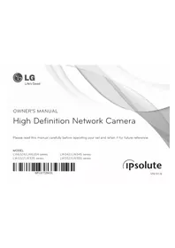
LW355-F - Surveillance Camera LG - Free user manual and instructions
Find the device manual for free LW355-F LG in PDF.


| Product Type | Security Camera |
| Brand | LG |
| Model | LW355-F |
| Resolution | 1080p Full HD |
| Lens | Wide-angle lens, fixed focal length |
| Night Vision | Infrared LEDs (up to 10 m range) |
| Field of View | Approx. 120 degrees |
| Connectivity | Wi-Fi 802.11 b/g/n (2.4 GHz) |
| Power Supply | DC 12V power adapter included |
| Dimensions (W x H x D) | Approx. 100 x 100 x 150 mm |
| Weight | Approx. 500 g |
| Storage | MicroSD card slot (up to 128 GB), cloud storage |
| Audio | Two-way audio with built-in microphone and speaker |
| Motion Detection | Yes, with push notifications |
| Mobile App | LG Smart Camera app for iOS and Android |
| Operating Temperature | -10°C to 50°C (14°F to 122°F) |
| Weatherproof | IP66 rated for outdoor use |
| Mounting | Wall or ceiling mount bracket included |
| Security Protocols | WPA2-PSK encryption |
| Maintenance | Clean lens and housing with a soft, dry cloth |
| Warranty | 1-year manufacturer warranty |
| Repairability | Detachable base and cover for easy access to SD card and reset |
Frequently Asked Questions - LW355-F LG
User questions about LW355-F LG
0 question about this device. Answer the ones you know or ask your own.
Ask a new question about this device
Download the instructions for your Surveillance Camera in PDF format for free! Find your manual LW355-F - LG and take your electronic device back in hand. On this page are published all the documents necessary for the use of your device. LW355-F by LG.
USER MANUAL LW355-F LG
High Definition Network Camera
Please read this manual carefully before operating your set and retain it for future reference.
MODEL
LW6324/LW6354 series
LW342/LW345 series
LW332/LW335 series
LW352/LW355 series

MFL67729435
ipsolute
1212 (V1.3)
Contents
Introduction....3
Features Chart....3
Operation and settings 4
Before using the system ....4
Recommended PC Requirements....4
Accessing the LG IP device....5
LG Smart Web Viewer Overview 6
Configuration menu overview....8
Configuring the LG Network Camera Device....8
Accessing the Configuration menu....8
System settings....9
Audio & Video settings....14
Network settings....16
User settings....21
Event settings....23
OSD Menu Setup....28
General Operation....30
Exposure settings....31
White Balance settings....33
Day/Night settings 33
3D-DNR setting....34
Privacy setting....34
Back Focus Setting....35
Special menu settings....36
SCENE mode setting (Option) 38
Reset setting....39
Reference 40
Troubleshooting....40
Open source software notice....43
Specifications....44
Introduction
The LG Network Camera is designed to use on an Ethernet network and must be assigned an IP address to make it accessible.
This manual contains instructions on how to install and manage the LG Network Camera in your networking environment. Some knowledge of networking environments would be beneficial to the reader.
Should you require any technical assistance, please contact authorized service center.
Features Chart
This table shows the differences between the models.
| Item LW63 | 24 LW6354 | LW332 LW3 | 35 LW342 | LW345 LW3 | 52 LW355 | ||||
| VA | No | Yes | No | Yes | No | Yes | No | Yes | |
| SD Card Yes Yes Yes Yes Yes Yes Yes Yes | |||||||||
| OSD | SCENE Mode | Yes Yes | Yes Yes Yes Yes | Yes Yes | |||||
| ALC2 No No No No | Yes Yes Yes Yes | ||||||||
Operation and settings
Before using the system
- Before using the LG IP device make sure the connections are correct and verify whether proper power supply is used.
- Check the connections of the LG IP device for the correct conditions.
- Check that the LG IP device is(are) connected to the network and that power is supplied.
- Once the connections are made you need to install the LG client program to the PC from which you want to access the device. The LG Smart Web Viewer program is automatically installed when you connect the LG IP device.
The LG Ipsolute VMS and the LG Smart Web Viewer program are the network program of the LG Video Server and the LG IP cameras. - To view streaming video in Internet Explorer, set your browser to allow ActiveX controls. If you find this message 'This website wants to install the following add-on: 'IPCam_Streamer.cab' from 'LG ELECTRONICS INC'", Click the yellow bar and install LG Smart Web Viewer Program on your computer. Please set your browser zoom level to 100%.
- The Layouts and the Live view pages may differ with different OS (Operating Systems) and Web Browsers.
- Care needs to be taken not to run any other applications when the Client Program is running as it may cause memory shortage.
Recommended PC Requirements
The LG IP device can be used with most standard operating systems and browsers.
| Items Requirements | |
| Operating System | Windows XP Professional, Windows VISTA, Windows 7 |
| CPU | Intel Core2 Guard Q6700 (2.66 GHz) or above |
| Web Browser | Microsoft Internet Explorer above the version 6.0 and below the version 8.0. |
| DirectX | DirectX 9.0c (Windows XP), DirectX 11 (Windows VISTA, Windows 7) or above |
| Memory 2 GB or above RAM | |
| Graphics Card 256 | MB or above Video RAM |
| Resolution 2040 x 1536 (with 32 bit color) or higher | |
Accessing the LG IP device
You can access the LG IP device by following the below steps.
1. Install LG Ipsolute VMS Program
2. Discover the LG IP device using the IP Utility
The IP Utility can automatically discover and display LG IP devices on your network.
The IP Utility shows the MAC address, IP address, Model name and so on.
Note:
The computer running the IP Utility must be on the same network segment (physical subnet) as the LG IP device.
2.1 Run the IP Utility program.
2.2 Click the [Search] button or select the [Search] option in the Device search menu.
After a few seconds the found LG IP devices gets displayed in the IP Utility window.
3. Logging in to the LG Smart Web Viewer
3.1 Run the IP Utility and find the LG IP devices.
3.2 When the LG IP devices appear in the IP Utility window, double-click IP address or right click on the same IP address and select "Connect to Web Page" to start the LG Smart Web Viewer. When accessing the LG Smart Web Viewer, the authentication dialog appears on the screen.
3.3 Enter the user name and password. (Note that the default administrator user name and password are "admin".)
3.4 Click the [OK] button and then the LG Smart Web Viewer is displayed in your browser.
Notes:
-
You can also access the LG Smart Web Viewer as shown below.
3.1 Start your Web browser.
3.2 Enter the IP address of the LG IP device in the address bar of the browse.
3.3 Enter the user name and password set by the administrator.
3.4 Click the [OK] button and then the LG Smart Web Viewer is displayed in your browser. -
The LG Smart Web Viewer needs more time to display it according to the network conditions.
- If the login window is not displayed, check the pop-up blocker. If you set the pop-up blocker, the login window is not displayed. You must allow the pop-ups.
- If you connect the LG Smart Web Viewer for the first time, the Security Warning window is displayed to install the LG Smart Web Viewer program. You must install the LG Smart Web Viewer program for using the LG IP device.
- If your computer or network is protected by a proxy or firewall, the proxy or firewall settings can prevent the LG Smart Web Viewer program. Change the proxy or firewall settings to activate the LG Smart Web Viewer program.
LG Smart Web Viewer Overview

| Item Description | |
| Change view sizeD1 | Select the video image size from the drop-down list.The initial view size is set to D1. |
| Video codecH.264 | Displays the current video codec of the selected video stream. |
| TCP connection | Check this option as the network connection type (TCP or UDP). If you check it, the client connects to the server using TCP connection. |
| Buffer 0ms | Select buffering time of live stream. |
| Click to display the check box of [Hostname], [Framerate] and [Bitrate] options. [Display] is displayed on left top of the live view window in order of selecting options.Video Analysis> Hide: Video Analysis display function is not in use.> MD: Displays the Motion Detection function to the live view window.Note:When you use the DPTZ function, all of Display function is deactivated for a while. | |
| Click to save the current image in JPEG format on your computer.1. Click the [Snapshot] button and then the Snapshot window is displayed.2. Click the [Save] button in the Snapshot window.3. Enter the file name (JPEG format) and select the folder to save it.4. Click the [Save] button to confirm it.5. Click the [Close] button in the Snapshot window to close it. | |
 OSD control OSD control | Displays the Camera OSD control window. Use these buttons to setup the Camera. This button does not appear on the screen if the login is other than the administrator. |
 | Select the video stream. From the Live view drop-down list, select the desired video image source.Note:You can set the stream configurations independently. This would facilitate the user to set the live view at his comfort. |
 | Provides all the necessary tools for setting up the device to your requirements. The user will need administrator level to do this.Note:If you want to exit the Configuration menu, select one of the video stream in the Live view drop-down list. |
 | Displays the current surveillance live screen. You can monitor the camera image on the live view window of the LG Smart Web Viewer. |
 | Click this button and drag the area to use PTZ function. Right-clicking the screen will bring up the previous magnification. (Color icon: On, Gray scale icon: Off.) |
 | 1. Click this button to open the folder browse window. Click the button again in next time, video is recorded automatically without selection of folder.Note:If you want to change the folder, move to other pages or press the refresh button.2. Recording button is activated and recording will be started.Note:If recording exceed the time(1 hour) or size limit (1 GB), recording is stopped automatically with warning.3. To stop the recording, click this button during the recording. |
 | Click this button to connect or disconnect the audio communication between the LG IP device and the connected PC.(Color icon: On, Gray scale icon: Off.) |
 | Click this button to switch the microphone off and on for the computer.(Color icon: On, Gray scale icon: Off.) |
| [KS85] | Click this button to switch the sound off and on, for the speaker of the computer.(Color icon: On, Gray scale icon: Off.) |
Configuration menu overview
The following table shows the list of menu items.
The configuration images are different from each model.
| Main Menu Sub | Menu Note | |
| System | Version | |
| Date & Time | ||
| Maintenance | ||
| Storage | ||
| Text Overlay Option | ||
| Log & Report | ||
| Language | ||
| Audio & Video | Camera | |
| Stream | ||
| Audio | ||
| Network | Basic | |
| RTP stream | ||
| TCP/IP | ||
| DDNS | ||
| IP filtering | ||
| SNMP | ||
| User Basic |
| Event | Event server | |
| Sensor & Relay | ||
| Motion detect | ||
| Triggered Event | ||
| Scheduled Event |
Configuring the LG Network Camera Device
The features and options of the LG IP camera are configured through the Configuration menu.
Only administrator-level users have permission to access the Configuration menu.
Accessing the Configuration menu
Click the [Configuration] button to display the LG Smart Web Viewer configuration window.
Warning
The Configuration setup should be made by qualified service personnel or system installers.
System settings
Version
Displays the current Model Name and Software version.

Date & Time

Time zone
Set the time difference from GMT in the area where the IP device is installed. Select the time zone in the area where the IP device is installed from the drop down list.
Time mode
Synchronize with NTP Server: Select if you want to synchronize the IP device's date and time with those of the time server called NTP (Network Time Protocol). Specify the NTP server's name. Click the [Test] button for connection test to the server.
Synchronize with personal computer: Select if you want to synchronize the IP device's date and time with your computer.
Synchronize manually: Select if you want to set the IP device's date and time manually. Select the year, month and date by clicking the calendar button. Set hour, minutes and seconds in the edit boxes.
Notes:
- When system reboot after time setting, time of system could be delayed. If you set the time correctly, set the [Synchronize with NTP server] option.
- Refer to NTP configuration as operation system of the Recording Server when the Recording Server use recording function and NTP server.
Server time
Server time: Displays the current date and time of the IP device.
- Save: Click this button to confirm the settings.
Maintenance

System reboot
Click the [Reboot] button to restart the IP device. It takes some minutes for the IP device to start again.
Restore and backup
Backup: To take a backup all of the settings. If necessary, it make possible to return to a backuped configuration.
- Click the [Backup] button.
- Click the [Save] button.
- Follow the instructions on the browser to specify the folder.
- Click the [Save] button to save the settings.
Restore:
- Click the [Browse] button.
- Find and open the file in which the configuration setting data is stored.
- Click the [Restore] button and the system settings will be restored and reboot the system.
Note:
Backup and Restore can happen on IP device having the same version of firmware. This feature is not intended for multi-configurations or for firmware upgrades.
Firmware
Upgrade
- Click the [Browse] button.
- Find and open the firmware file.
- Click the [Upgrade] button to update the firmware.
Note:
When you upgrade the system, it may take some minutes to be done. Do not close the browser while the upgrade is in progress. If you close the browser, it may cause a malfunction. You should wait until the confirmation window is displayed. When the upgrade is finished, the confirmation window will be displayed.
Initialize: The [Initialize] button should be used with caution. Clicking it will return all of the IP device's settings to the factory default values. (Except for the Network settings, PTZ Protocol and Preset settings. The option depends on the model.)
Storage

General
Overwrite: If the micro SD card has insufficient space and this option will be activated. It will overwrite the oldest data.
DiskFull Notification: Sends an warning e-mail to the SMTP server when the micro SD card has fully recorded. Select the SMTP server from the drop-down list. You should register the SMTP server on the Event server setting to set this function.
Network Failure Recording: Select the check box to activate the micro SD card recording function. If the system does not work with recording server, the system will record the data to the micro SD Card. When the system connect to the recording server again, the recorded data of the micro SD card will transfer to the recording server automatically.
Recording Server IP: Enter the recording server IP.Set as NTP server IP: Click this button to use the entered Recording Server IP as the NTP server IP.
Notes:
- The recorded file name is made automatically as the "[Created date of the file]_[GMT Recording Time]+(-) [Value of the Local Time minus GMT Time (Second)]_[Use or not of the Daylight saving time(N/D)][Stream index] [DeleteFlag].DAT" type.
- If the capacity of the SD card remains less than 200 MB, stop recording or overwrite new file after delete old one as [Overwrite] setting. The overwritten file can not play or may malfunction when you download.
- Recorded file on the SD card, is recording 1 frame per second when set video codec to MJPEG.
Device Management
Using the micro SD card
- Insert the micro SD card carefully to the micro SD card slot of the camera.
- Click the [Mount] button. If the micro SD card is mounted to the system correctly, the [Mount] button will be changed to the [Unmount] button.
- Displays the information of the[Disk ID], [Status], [Capacity] options.
Notes:
- When the micro SD card is mounted, you should format the micro SD card. After the micro SD card format is finished, you should click the [Mount] button to use it.
- When you use the micro SD card format function, it may not progress immediately. In this case, you should try it again after waiting a few minutes.
Remove the micro SD card
- Click the [Unmount] button. If the micro SD card is unmounted from the system correctly, the [Unmount] button will be changed to the [Mount] button.
- Remove the micro SD card from the micro SD card slot of the camera.
Note:
When you use the Unmount function, it may not progress immediately. Operations such as recording of the system and reading of data are required stop time before the Unmount function is activated. You should try it again after waiting a few minutes.
File Format
File Format: You can selects the Recording File Format(AVI or DAT). Recording, Search and Download are available according to the setting.
Notes:
- SD Recording or FTP(Video) Sending Format are set according to the setting. When you select to AVI, [Auto Recording function] may not be activated in case of network error.
- IP Camera's time will be appeared in players based on DirectShow such as Windows Media Player and MPlayer.
File Management
Displays the recorded file of the micro SD card on the list. Click the [Search] button to display the recorded file. The list will be updated when you click the [Search] button.
To view the recorded file of the micro SD card
-
Select the search option.
-
All: Search the all recorded files in the micro SD card.
-
Some: You can set the search condition by using the date and time options.
-
Click the [Search] button and then the search result is displayed on the list.
Download: You can download the recorded data of the list to your PC. Select a recorded file on the list and click the [Download] button. The two confirmation window is displayed. You should download the all files that the recorded file(*.DAT) and information file(*.INFO). You can download as AVI file according to File format.
Notes:
- It is recommended to deactivate the [Overwrite] function before you download the file. When [Overwrite] function is activated, the downloading file might be overwritten, if the micro SD card has insufficient space.
- The downloaded file can be played by using the LG File player.
Remove: Delete file from the SD card.
Text Overlay

Text Overlay
Enable: Set to ON or OFF. Setup menu is appeared when selects ON.
Date & Time : Select the ON to display time and date of Client PC.
Channel Name: Enter the channel name you want to use. You type the Channel Name, it will be displayed whether you select the ON or OFF.
Flickering: Set to On or OFF.
Position: You can designate the position of text from drop down list.
- Save: Click this button to confirm the settings.
Log & Report

Log & Report status
The System log provides a summary of the status of the IP device. The unit records the data of the software activity in a file.
View Log: Click this button to display the system log information.
- Download: Click this button to see the log information of system.
View report: Click this button to display the report of the system.
- Download: Click this button to see the report information of system.
Note:
The downloaded file is a UNIX type. If you open the file in Microsoft Notepad, it will display the text as if the file contained no line breaks at all.
Language

Language list
Select a language for the LG Smart Web Viewer configuration menu and information display.
- Save: Click this button to confirm the settings.
Audio & Video settings
Camera
![Menu System Audio & Video Stream Audio Network User Event Preview Camera General Contrast 50 [0-100] Standard NTSC - CaptureMode 4.3 or 2.4 Save Default](/content/2026/08/1570425/images/0641c5613399a25eb24099e68c5e5427f7d0dcada14f9bf88e98d6befa42bc91.jpg)
Preview
You can preview the camera image on the preview window.
General
Contrast: Edit the contrast value from 0 to 100. Selecting 100 provides the image with the highest contrast.
Standard: Displays the video standard of the camera.
CaptureMode (Option): Select the capture mode.
Note:
If you change the CaptureMode option, the Privacy, WDR/BLC and HSBLC settings on the OSD menu are initialized.
- Save: Click this button to confirm the settings.
- Default: Click this button to restore the IP device back to original factory settings.
Note:
The Capture mode is not initialized.
Stream
| Mean | Stream | |||
| System | Resolution | |||
| Audio & Video | HD | 1280x1024 | SD | 01 Save |
| Camera | Profile | Profile(HD) | ||
| System | Enable | 0 | ||
| Audio | Video codec | # 264 | Resolution | 1280x1024 |
| Network | Maximum Frame rate | 30 [1-36 fps] | GOP size | 30 [1-30] |
| User | Quality | VER | Stream quality | Medium |
| Event | Alias | Profile 1 | ||
| Save | ||||
Resolution
HD: Displays the maximum image size of the camera.
SD: Select the output image size of the camera.
Profile
Enable: Click to activate the stream function.
Video codec: Select the video mode (Codec) from the dropdown list. The viewer can choose among MJPEG, H.264 and H.264_HIGH.
Maximum frame rate: Set the frame rate of the image.
GOP size: It means "Group of Pictures". The higher the GOP, the better is the video quality of the camera. Edit the value of GOP from 1 to 30. This setting is valid for H.264 video format only.
Quality: Select the Quality.
- VBR: The bit rate may vary depending on the complexity of the video to meet the selected quality.
- CBR: The video quality may vary in order to preserve a
constant bit rate.
Stream quality: If the [Quality] option set to VBR, this option is displayed. Select the stream quality from the drop down box, the camera supports five types. (Highest, High, Medium, Low and Lowest)
Alias: Enter the profile name you want to use.
Bit rate: If the [Quality] option set to CBR, this option is displayed. Edit the bit rate value from 256 kbps to 10 240 kbps.
Note:
If the 'Bit rate' is configured too low with high resolution, the actual frame rate will decrease because of narrow bandwidth. So you need to set or change the 'Bit rate' to high value.
- Save: Click this button to confirm the settings.
Region Of Interest
![Profile Profile4(ROI-1) Enable Video codec H 264 Maximum Frame rate 30 [1~30 fps] GDP size 30 [1~30] Quality VBR Stream quality Medium Alias Profile4 Region Of Interest 1 Save](/content/2026/08/1570425/images/beb14136a0dc4ca4161030d30bb6c1d05c3ea34477e83bf6f856104c14435437.jpg)
You can set and streaming the desired area on the live view window to use ROI(Region Of Interest) function. Select Profile4(ROI-1) to Profile7(ROI-4).
Enable
- Click to activate the [Region Of Interest] window. You can add the 4 windows maximum for ROI function.
- Click the edge or corner of the window box to adjust the window size.
- Click the [Save] button to save the settings.
Note:
ROI area can not overlap with each other.
Audio

Audio In
Enable: Click the check box if you want to send the audio from the microphone input connector.
Note:
The Clients connected to the IP device remain unaffected with additional changes made in the setting.
Audio type: Select the codec when you send the audio from the microphone input connector.
Audio Out
Enable: Click the check box to output the audio from the speaker.
- Save: Click this button to confirm the settings.
Network settings
Basic
![Menu System Audio & Video Network Basic General MAC address: 8878 58 AC 38 58 Port & Encryption Web port 80 [80, 1025-65635] RTSP port 554 [554, 1025-65535] Network encryption HTTP ARP ping Enable ARP ping to configure IP address. ✓ Save Event](/content/2026/08/1570425/images/5d3a1401887fe533626f1d998889c850bf24f6af5f7e97a865b694ef979eed6b.jpg)
General
MAC address: Displays the MAC address.
Port & Encryption
Web port: The default HTTP port number (80) can be changed to any port within the range 1 025 to 65 535.
RTSP port: Check RTSP port. The default port is 554. Other ports can be selected within the range 1 025 to 65 535.
Network encryption: Select the HTTP or HTTPS option for security.
Note:
The RTSP port number should not be same with the web port number.
ARP Ping
Enable ARP Ping to configure IP address: Check to enable ARP ping.
- Save: Click this button to confirm the settings.
RTP stream
RTP (Real-time Transport Protocol) is an internet protocol that allows programs to manage the real-time transmission of multimedia data, via unicast or multicast.
![RTP stream Profile Profile1(KD) RTP unicast RTP multicast IPv4 address 235.255.214.42 [224.0.0.0 - 239.255.255.256] Base RTP port 10000 [10000 - 65538 EVEN] TTL TTL 7 [1 - 256] Save Audio & Video Network Basic TCP/IP DDNS IP filtering SNAP User Event](/content/2026/08/1570425/images/33ec46e47b1b55437144efca64c2d1c1bfe8a390049edd0dde3e0609a9477ede.jpg)
Profile
RTP unicast: When enabled the transmission of the data to the specified equipment happens on a network specifying a single address.
RTP multicast: When enabled it reduces the transmission load on the camera by making the computer of the same segment network receive the same transmission data. When multicast option is checked then select Video Port number, Audio Port number and Data port number.
- IPv4 address: Set the IP address for RTP multicast.
- Base RTP port: Enter the port number of even number used for the multicast streaming. Each profile uses successive 6 port number which starts from [Base RTP port]. It is initially set to 10 000 and you can edit this between 10 000 and 65 530.
Note:
Each profile using multicast needs its own multicast IP address and port numbers to avoid address conflict. When more than 2 profiles use same multicast IP address, each [Base RTP port] number should be distinguished from the other port number more than 6 at least.
TTL
TTL: This option indicates the Time-To-Live of multicast packets. The default setting is 7, and the allowed TTL range is from 1 to 255.
• Save: Click this button to confirm the settings.
TCP/IP

IPv4 address status
Automatically set with DHCP: Select this option when a DHCP server is installed on the network to allow IP address assignment. With this setting, the IP address is assigned automatically.
- Notify to SMTP server, if IP address is changed: If you select this option, the user get a notification mail telling about changing of IP of the IP device.
Notes:
- You should register the SMTP server on the Event server setting to set this function.
- If you select [Automatically set with DHCP], the camera obtain IP address from DHCP server after IP address is set "192.168.0.16".
Statically set: Select this option when you set a fixed IP address, with this setting, specify the IP address, Subnet mask and default gateway manually.
- IPv4 address: Enter an IP address.
- Subnet mask: Enter a subnet mask address.
- Gateway: Enter the gateway address.
DNS server status
Primary DNS server: Enter the Primary domain name server that translates the hostnames into IP address.
Secondary DNS server: Enter the Secondary DNS server address that backups the Primary DNS.
- Save: Click this button to confirm the settings.
IPv6 address status
Enable: Click the check box if you want to use the IPv6 address.
Mode
- Manual: Select this option when you set a fixed IP address manually.
- Basic: Select this option to allow IPv6 address assignment based on the Mac address. With this setting, the IP address is assigned automatically.
- DHCPv6: Select this option when exist a DHCPv6 server in network. If DHCPv6 server is not existed or temporary disability, it requests assignment every 3 minutes.
IPv6 address: You can enter the IP address when you select the Manual mode. It alarms when you enter the invalid IP address.
DDNS
This free service is very useful when combined with the LG DDNS Server. It allows the user to connect the IP device using the URL, rather than an IP Address. This also solves the problem of having a dynamic IP address.

DDNS status
Don't use DDNS server: Disable the DDNS function.
Use DDNS server: Enable the DDNS function.
- Provider: Displays the DDNS provider.
- Hostname: Enter the hostname you want to use.
- Save: Click this button to confirm the settings.
IP filtering
The access of the IP addresses in the list are allowed or denied according to the choice made in the drop-down list of the Basic policy option. The administrator can add up to 10 IP address entries to the list (a single entry can contain multiple IP addresses). The users from these IP addresses need to be specified in the user list with the appropriate access rights. The IP list is to control the access permission of clients by checking the client IP address.

IP list
Basic policy: Select the basic policy type.
- Allow all: Allow all the IP address basically, but the IP addresses in the list are denied.
- Deny all: Deny all the IP address basically, but the IP addresses in the list are allowed. It needs at least one IP address to activate this function.
- Save: Click this button to confirm the settings.
-
Add: Click this button to add the IP address.
-
Click the [Add] button.
-
Set the IP options.
-
Alias: Enter the alias.
- From: Enter the start IP address for the IP filtering.
- To: Enter the end IP address for the IP filtering.
Note:
If you want to deny or to allow a range of IP addresses, enter the start IP address to "From" and the end IP address to "To". You can also add an IP address by entering the same IP address to "From" and "To".
- Click the [Save] button.
- Repeat the steps 1 to 3 to add additional IP address.
- Remove: Click this button to delete the IP address.
- Select the alias from the list.
- Click the [Remove] button. The IP address will be deleted.
IPv6 address
- Add: Click this button to add the IP address.
- Click the [Add] button.
-
Set the IP address option.
-
Alias: Enter the alias.
-
IPv6 address: Enter the IP address for IP filtering.
-
Click the [Save] button.
- Repeat the steps 1 to 3 to add additional IPv6 address.
- Remove: Click this button to delete the IPv6 address.
- Select the alias from the list.
- Click the [Remove] button. The IPv6 address will be deleted.
SNMP
The Simple Network Management Protocol (SNMP) is an application protocol to exchange the management information of network devices.

SNMP v1/v2c
Enable SNMP v1/v2c: Selects when SNMP is allowed access to this device.
Read Community: Specifies the SNMP management community in which you want to read this system.
Write Community: Specifies the SNMP management community in which you want to write this system.
SNMP v3
Enable SNMP v3: Selects when SNMP v3 is allowed access to this device. It supports authentication and encryption.
SecurityName: Type the security name for the SNMP.
Password: Type the password for the SNMP.
User settings
Basic
The IP device is shipped with the login rights of administrator only. If others need to access the IP device excluding the configuration a login with viewer rights need to be created. A maximum of 50 users can be created.

User list
Add the User
You can register a new user with various access rights.
- Click the [Add] button. User setting dialog is displayed.
- Enter the new User ID and Password. (Should have a minimum of 4 characters and preferably a combination of alphanumeric.)
-
To confirm the password, retype the password that you typed in the Password box.
-
Select the authority from the drop down list to provide the access rights to each user and then click the [Save] to confirm your selection.
-
Administrator: Allows you to operate setup menus and to view live images.
- Power user: Use of the limited functions of the system. (The Configuration menu is not allowed.) A power user can use the Live View, OSD control and audio functions.
- Normal user: Provides the lowest level of access, Allows to view live images only.
- Custom user: The user can login and view the live stream image only when the "Enable anonymous login" option is checked to enable it.
Note:
Remember the password.
Edit the registered user
You can change the password or authority.
- Choose the user ID and then click the [Edit] button.
- Change the Password or Authority, then click the [Save] button to confirm your selection.
Delete the registered user
- Choose the user ID you want to delete.
- Click the [Remove] button.
Note:
The default administrator user ID 'admin' and 'anonymous' are permanent and cannot be deleted.
Anonymous
Enable anonymous login
Check the box to enable anonymous user login - allows the user access for only viewing the live stream image.
Maximum RTP stream connection
Maximum number of simultaneous stream connection:
Set this number to limit the number of simultaneous stream connections.
The connections depend on the stream configuration as shown in the following Maximum RTP stream connection by stream configuration.
- LW332/LW335/LW6354/LW6324 Series
| Video Codec | Resolution | Frame Rate | Quality | Maximum RTP stream |
| H.264 720 | p 30 HIGHEST | Up to 10 | ||
| MJPEG 720 | p 20 HIGHEST | Up to 7 |
- LW342/LW345 Series
| Video Codec | Resolution | Frame Rate | Quality | Maximum RTP stream |
| H.264 | 1080p | 30 | HIGHEST | Up to 5 |
| H.264 | 1080p | 30 MEDIUM Up to 10 | 10 | |
| H.264 720 | p 30 HIGHEST | Up to 10 | ||
| MJPEG | 1080p | 10 | HIGHEST | Up to 3 |
| MJPEG 720 | p 20 HIGHEST | Up to 7 | ||
- LW352/LW355 Series
| Video Codec | Resolution | Frame Rate | Quality | Maximum RTP stream |
| H.264 2040x1536 20 HIGHEST Up to 10 | ||||
| MJPEG 2040x1536 5 HIGHEST Up to 7 | ||||
Note:
Preview window of the IP device setting and preset setting are affected by this setting.
- Save: Click this button to confirm the settings.
Event settings
Event Server
Event Servers are used to receive the recorded video clip and/or notification messages.

FTP server list
Image files can be transferred to the FTP server within the scheduled time. Image file that has been recorded linked to an external event is sent to the FTP server periodically.
To add the FTP server
- Click the [Add] button. FTP server setting window is displayed.
-
Set the FTP server options.
-
Alias: Type the FTP Server name to upload the image files.
- Address: Enter the FTP server's IP address.
-
Port: Enter the port number. The default FTP port is 21.
-
User ID: Type the user name for the Folder shared in the FTP server.
- Password: Type the password for the folder shared in the FTP Server.
- Folder: Type the path with the folder that is shared in the FTP server.
-
Test: Select [Test] to test the FTP server.
-
Click the [Save] button to confirm the settings.
To edit the FTP server
- Choose the FTP server in the FTP server list.
- Click the [Edit] button.
You can check or edit the FTP server options.
To delete the FTP server
- Choose the FTP server in the FTP server list.
- Click the [Remove] button. This would remove the FTP server from the list.
SMTP server list
By selecting the e-mail option, a still image of the event is captured and an e-mail with the attached image file is sent to the specified mail address.
To add the SMTP server
- Click the [Add] button. SMTP server setting window is displayed.
-
Set the SMTP server options.
-
Alias: Enter the SMTP server name.
- User ID: Enter the user ID of the SMTP server. This would be the one who owns the mail account.
-
Password: Enter the password of the SMTP server.
-
Address: Enter the SMTP server address.
- Port: Enter the port number. The default port is 25.
- Enable SSL: Check when use the SSL (Secure Socket Layer) protocol. SSL protocol is cryptographic protocols that provide secure communication on a network.
- Receiving address: Type the recipients e-mail address. You can specify only one recipient e-mail address.
- Administrator address: Type the e-mail address of the administrator.
- Subject: Enter the subject/title of the e-mail.
- Message: This message can describe the information of the acquired IP address, etc.
-
Test: Select [Test] to test the SMTP server.
-
Click the [Save] button to confirm the settings.
To edit the SMTP server
- Choose the SMTP server in the SMTP server list.
- Click the [Edit] button.
You can check or edit the SMTP server options.
To delete the SMTP server
- Choose the SMTP server in the SMTP server list.
- Click the [Remove] button.
Sensor & Relay
![Sensor & Relay System Audio & Video Network User Event Event server Motion detect Triggered Event Scheduled Event Sensor Enable Alias Type [2] Sensor Normal open Relay Control duration (1-85400(24hour)second) 5 Alias Type Control relay Relay Normal open Run Stop Save](/content/2026/08/1570425/images/04ec193289b2fb49643b72fb468a242dcd9c2f9c84aad6acaa6428b87a60eb4c.jpg)
Sensor
Enable: Marks up when you want to activate the sensor.
Alias: Displays the sensor name.
Type: Select the sensor type.
Relay
Control duration: Enter the relay time.
Alias: Displays the relay name.
Type: Select the relay type.
Control relay
- Run: Click to activate the relay.
- Stop: Click to stop the relay.
- Save: Click this button to confirm the settings.
Motion detect

Preview
You can preview the motion detection window on the preview window.
General
Sensitivity: Enter the sensitivity to detect an object in motion.
Save: Click this button to confirm the settings.
How to set the motion detect window
- Click the [Add] button. The motion detect window is displayed. You can add the five windows maximum for motion detection area.
- Set the [Sensitivity] option.
- Click the edge or corner of the window box to adjust the window size for motion detection.
- Click the [Save] button to save the settings.
Notes:
- You can reset the window size. Click one of the window edge or corner and drag & drop to reset the motion detection area.
- Motion Detection can be activated when at least one of channels(Master/Slave) is enabled, Video codec is set to H.264 and GOP size is more than 2.
Triggered Event
When an event (VA/ Motion detect/ Sensor Event) occurs, this unit records the live images and routes as configured.
| Triggered Event list | ||||||
| Trigger | Relay | FTP(VIDEO) | SMTP | SDCard Recording | FTP(JPEG) | |
| Sensor | Relay | |||||
| VA_Intrusion-0 | ||||||
| VA_CrossingLine-0 | ||||||
| VA_ObjectCounting-0 | ||||||
| VA_ObjectRemoval-0 | ||||||
| VA_Tampering-0 | ||||||
| MotelnDetled-0 | ||||||
Event schedule list
To edit the Event Schedule
- Select the Trigger event and click the [Edit] button. Event schedule window is displayed.
-
Set the options.
-
Trigger: Display the selected trigger event and the current state of trigger. Current state of trigger is Displayed to On or Off.
• Time: Sets the weekday, Start, Finish, Pre alarm, Post alarm and Ignore interval time options.
• Action: Selects the options. This occurs when the event runs. -
FTP server/SMTP server: Uploading of images to an FTP server, or e-mail notification.
- Control relay(Optional): The relay is activated or deactivated.
- SDCard recording: Record on the SD card when the event runs.
- FTP server(JPEG): Sends the JPEG Image to the FTP server. Image file and suffix setting is available. You can select Date/Time or Sequence of Suffix.
• Stream: Selects the stream of the connected camera.
- Programmable Alarm(Optional): When the sensor event is activated, the camera will start the recording with the setting value of these options. Using this function, you can get high quality recorded image.
-
Click the check box if you want to activate this function.
-
Sets the options.
-
Click the [Save] button to confirm the settings.
Notes:
- You should register the SMTP and FTP server on the Event server setting to set this function.
- Recording of event(VA/Motion detect/Sensor event) runs every 5 minutes split file.
• Used stream is profile of Master or HD resolution in case of FTP(JPEG) transmission.
Scheduled Event
![Scheduled Event System Audio & Video Network User Event Event carrier Sensor & Relay Magnet detect Triggered Event Scheduled Event Activation Time Always Only scheduled time Action EDC card recording Protel(0) FTP server(IPED) test Always Send Image per 5 seconds [Esecond-1] Base File Name Data/Flam…](/content/2026/08/1570425/images/76c00388c8df7b422418f7be6edeedb0045ae8181c5cbabd37a4f8ffe9700b67.jpg)
Activation Time
Always : You can use always by using the FTP server regardless of activation time.
Only scheduled time: Continuously record according to the set time and the selected weekday.
Action
Set the below option.
SD Card recording : Record to SD Card when event occurs. Selects the camera stream for SD card recording.
FTP server(JPEG) : Upload the image or send the e-mail to the FTP server. Send Image per, Base File Name and Suffix setting are available.
Notes:
- You can select through drag of Activation Time table that is possible to select according to weekday and time.
- Used stream is profile of Master or HD resolution in case of FTP(JPEG) transmission. If always checkbox next to FTP(JPEG) is checked, FTP(JPEG) is always enable regardless of the activation time.
- Save: Click this button to confirm the settings.
OSD Menu Setup
The following table shows the list of menu items and options.
These options are depending on models.
The OSD images are different from each model.
| Main Menu | Sub Menu Contents | ||
| EXPOSURE ELC/ALC, ALC2 (LW355/LW352 only) | WDR/BLC OFF | /WDR/BLC/HSBLC | |
| BRIGHTNESS 0 to 100 | |||
| AGC OFF/LOW/MIDDLE/HIGH | |||
| SHUTTER The option depends on the model. | |||
| SENS-UP OFF | |||
| AUTO | |||
| EXIT RET/TOP/END | |||
| WHITE BAL ATW | - | ||
| AUTO | - | ||
| AWC→PUSH | - | ||
| MANUAL | COLOR TEMP | ||
| RED | |||
| BLUE | |||
| EXIT RET/TOP/END | |||
| DAY/NIGHT AUTO LEVEL LOW/ MIDDLE/ HIGH | |||
| DWELL TIME The option depends on the model. | |||
| EXIT RET/TOP/END | |||
| DAY | - | ||
| NIGHT | - | ||
| 3D-DNR OFF | - | ||
| LOW | - | ||
| MIDDLE | - | ||
| HIGH | - | ||
| PRIVACY OFF | - | ||
| ON COLOR RED 0 to 255 | |||
| GREEN 0 to | 255 | ||
| BLUE 0 to | 255 | ||
| EXIT RET/TOP/END | |||
| TRANSPARENCY | 0 to 16 | ||
| RECTANGLE MASKNUMBER | AREA1 to AREA8 | ||
| RECT. DISPLAY | ON/OFF | ||
| HEIGHT | 4 to 100 | ||
| WIDTH | 4 to 100 | ||
| MOVE Y 2 to 98 | |||
| MOVE X 2 to 98 | |||
| EXIT | RET/TOP/ END | ||
| PRIVACY | ON CIRCLE MASK | NUMBER | AREA1 to AREA2 |
| CIR. DISPLAY | ON/OFF | ||
| HEIGHT | 1 to 15 | ||
| WIDTH | 1 to 15 | ||
| MOVE Y | 0 to 100 | ||
| MOVE X | 0 to 100 | ||
| RADIUS SIZE | 0 to 100 | ||
| EXIT | RET/TOP/ END | ||
| POLYGON | AREA1 to AREA2 | ||
| ON/OFF | |||
| - | |||
| - | |||
| EXIT | RET/TOP/END | |||
| EXIT RET/TOP/END | ||||
| BACK FOCUS MANUALADJUST | - | |||
| ABF PUSH | - | |||
| FOCUSRESET | - | |||
| D/N ABF OFF/ON | ||||
| EXIT RET/TOP/END | ||||
| SPECIAL D-ZOOM OFF | ||||
| ON ZOOM | ||||
| PAN | ||||
| TILT | ||||
| EXIT | ||||
| D-EFFECT OFF/V-FLIP/MIRROR/ROTATE | ||||
| SHARPNESS 0 to 68 | ||||
| COLOR OFF/ON | ||||
| PIP OFF | ||||
| ON | WINDOW MOVE | |||
| IMAGE MOVE | ||||
| IMG SIZE | ||||
| EXIT | ||||
| STABILIZER | OFF/ON | |||
| USER TITLE | OFF/ON | |||
| LANGUAGE | The option depends on the model. | |
| EXIT RET/TOP/END | ||
| SCENE MODE | STD | - |
| BKLT | - | |
| LOWLIT | - | |
| OUTDOOR | - | |
| INDOOR | - | |
| TRAFFIC | - | |
| USER | - | |
| RESET | CAMERA REBOOT | - |
| FACTORY RESET | - | |
| EXIT RET/TOP/END | ||
| EXIT | - | - |
General Operation
- Click the [OSD control] button on the LG Smart Web Viewer.
- Click ← button on the OSD control window. The camera setting menu appears on the live view window.

- Use ↑ o ↓ button to select an option then click ↓ button. Submenu appears.
- Use ↑ o ↓ button to select a submenu option.
- Use o button to select a value.
-
Select [EXIT] option then click button to exit the setup menu. In the submenu, use ▼r button to select the [EXIT] then use ▼ or ▼button to select a mode and click button to exit the setup menu.
-
RET: Return to the previous.
- TOP: Return to the CAMERA SETTING menu screen.
- END: Exit the setup menu.
Notes:
- button: Used to move upper direction on the menu screen.
- Button: Used to move lower direction on the menu screen.
- button: Used to increase the value selected in the menu.
- Button: Used to decrease the value selected in the menu.
- Button: Executes selections and displays a submenu for an item with the mark.
Exposure settings


You can set the exposure options using the EXPOSURE menu.
- Select [EXPOSURE] option on the [CAMERA SETTING] menu.
- Use or button to select a mode.
- Press button and the EXPOSURE menu appears.
Notes:
• ELC Mode is right for outdoor scenes.
• ALC Mode is right for indoor scenes.
WDR/BLC
Use WDR/BLC option to view the object clearly in backlight conditions.
- Select [WDR/BLC] option on the [EXPOSURE] menu.
- Use o button to select a mode then click button.
- WDR: WDR (Wide dynamic range) feature can be very helpful to cope with very challenging lighting conditions. It is capable of capturing both of the dark part and bright part and combining the differences into a scene to generate a highly realistic image as original scene. Set the WDR limit.
ACE (Adaptive Contrast Enhancement): This function is used when you want to display dark areas of WDR brightly.
- BLC: Camera's backlight compensation feature helps alleviate issues of visibility in high contrast areas. Set the BLC limit.
- HSBLC: Use for masking brightness of the specific area to view the subject more clearly. The HSBLC mode is automatically activated only in low luminance scene.
AREA SETTING: Use button to select area then use button to select [ON] or [OFF]. Click button to exit the area setting menu.
GRAY SCALE: Use □ or □ button to select a gray scale.
USER SCALE: Use 📄 or 📝 button to select a bright level.
MASK: Use 📋 r 📋 tton to select [ON] or [OFF]. If you set the MASK to ON, the mask function is activated only when the HS BLC is activated by auto mode.
• OFF: Not in use.
BRIGHTNESS
You can increase the brightness of the darkened video. If you set the brightness to lower value, the image gets darkened. If you set the brightness to higher value, the image gets bright.
- Select [BRIGHTNESS] option on the [EXPOSURE] menu.
- Use ← o→ button to set the bright level.
AGC (Automatic Gain Control)
If the images are too dark, change the maximum [AGC] value to make the images brighter.
- Select the [AGC] option on the [EXPOSURE] menu.
- Use ← o→ button to select a mode.
SHUTTER (Shutter Speed)
Select the desired shutter speed for camera exposure. You can change the shutter speed to higher speed to capture fast-moving subjects, though the image becomes darker.
- Select [SHUTTER] option on the [EXPOSURE] menu.
- Use o button to set shutter speed.
Note:
If you set the shutter speed value in ALC2 mode, it is maximum value. When the camera is activated with ALC2 mode, the shutter speed is arrived maximum value and then the camera is change to iris control mode automatically for the camera exposure.
Select ALC mode when flicker is occurred in indoor environment.
SENS-UP
If pictures are not clear due to darkness, this SENS-UP operation would increase the sensitivity of picture.
- Select [SENS-UP] option on the [EXPOSURE] menu.
- Use o button to select a mode.
• AUTO: Adjust the sensitivity of the picture automatically.
SENS-UP LIMIT: Use 📋 button to set the SENS-UP limit.
EXIT: Select a mode and click button to exit the menu.
Note:
If you set to one of the SHUTTER options except AUTO on the [SHUTTER] menu or [AGC] to [OFF], the [SENS-UP] setting is not available and [---] mark is displayed.
White Balance settings
Select the method by which the camera shifts its output colors to compensate for the color of a light source.

- Select the [WHITE BALANCE] option.
- Use o button to select a mode then click button.
- ATW (Auto-Tracing White Balance): In this mode, white balance has better coverage than auto. Proper white balance may not be obtained under the following conditions:
When the scene contains mostly high color temperature objects, such as a blue sky or sunset.
When the scene is dim.
• AUTO: You can set the white balance options automatically.
- AWC → PUSH: If you select the AWC → PUSH mode, you will be able to set up the White Balance automatically using button.
• MANUAL: You can set the white balance options manually.
COLOR TEMP: Use or button to select a function.
- INDOOR: The color temperature range for the proper white balance is approximately 3 200 K.
- OUTDOOR: The color temperature range for the proper white balance is approximately 5 100 K.
RED: Set the desired red value.
BLUE: Set the desired blue value.
Day/Night settings

- Select [DAY/NIGHT] option.
- Use o button to select a mode for DAY/NIGHT function.
• AUTO: DAY/NIGHT mode changes automatically.
Note:
If you set the AGC to [OFF] on the [EXPOSURE] menu, the AUTO mode of the DAY/NIGHT function is not available and [---] mark is displayed.
LEVEL: Use or Button to select a level.
DWELL TIME: Use ←r button to select a dwell time.
• DAY: Color mode enabled.
• NIGHT: Black-and-white mode enabled.
3D-DNR setting

- Select [3D-DNR] option.
If pictures are not clear due to noise, this option would reduce the noise of picture.
- Use ← o→ button to select an option.
Notes:
- If you set the AGC to [OFF] on the [EXPOSURE] menu, the [3D-DNR] function is not available and [---] mark is displayed.
- When you use this function, the afterimage may occur.
Privacy setting
This function is aiming at the protection of personal privacy. The selected part is not displayed on the screen.

- Select the [PRIVACY] option.
- Use o button to select [ON] and press The PRIVACY SETUP menu appears.
• COLOR : You can make any color by adjusting R.G.B LEVEL.
• TRANSPARENCY : You can adjust the transparency of MASK.
- RECTANGLE :
Use 📋 button to select a mask on the [MASK NUMBER].
Use 📄 button to set up the [ON] or [OFF] on the RECT. DISPLAY option.
Use ↑r to select an option then use or button to adjust the option.
- HEIGHT: Increase or decrease the vertical size of the mask.
-
WIDTH: Increase or decrease the horizontal size of the mask.
-
MOVE Y: Moves vertical position of the mask.
- MOVE X: Moves horizontal position of the mask.
CIRCLE:
Use ▼r button to select a mask on the [MASK NUMBER].
Use ▼r button to set up the [ON] or [OFF] on the CIR. DISPLAY option.
Use ↑r to select an option then use or button to adjust the option.
- HEIGHT: Increase or decrease the vertical size of the mask.
- WIDTH: Increase or decrease the horizontal size of the mask.
- MOVE Y: Moves vertical position of the mask.
- MOVE X: Moves horizontal position of the mask.
- RADIUS SIZE : You can adjust the RADIUS SIZE.
- POLYGON:
Use ←r button to select a mask on the [MASK NUMBER].
Use ▶r button to set up the [ON] or [OFF] on the POLY. DISPLAY option.
Use the 📄 → and 📋 button to draw the polygon by moving each vertex on the [POLYGON DRAW]. Each movable vertex will be displayed as a black square spot each time you click the 📋 button.
Use the ←, → and ↓ button to move the polygon on the [POLYGON MOVE].
Back Focus Setting
The back focus function is activated automatically according to your setting. And also, when the Day&Night function is activated, the Back Focus function is activated automatically.


MANUAL ADJUST
You can adjust the back focus manually.
- Select the [MANUAL ADJUST] option on the [BACK FOCUS] menu and then click 📋utton.
- Use button to adjust the focus point then click button to exit the menu.
ABF ADJUST
You can adjust the back focus automatically.
- Select the [ABF ADJUST] option on the [BACK FOCUS] menu and then click 📋 button. This function will be activated automatically to adjust the back focus.
- When the focus setting is finished, click 📄 button to return to the previous menu.
FOCUS RESET
Reset the focus point to factory default position.
Select the [FOCUS RESET] option on the [BACK FOCUS] menu and then click 📋 button. The screen will be dim.
Use the [Manual Adjust] or [ABF push] option to adjust the focus.
Note:
You can reset the focus using the ABF button. When you keep pressing ABF button about 4 seconds, the camera will reset the focus.
D/N ABF
You can set the Day&Night function with ABF function.
Use 📋 button to select a option.
- ON: If you set to On, the ABF function will be activated automatically when the D/N function is activated.
• OFF: Not used.
Special menu settings


Note:
If the video image size is 4:3 mode, the D-ZOOM, D-EFFECT, PIP and STABILIZER function is not activated for LW352 and LW355 models.
D-ZOOM
You can select the digital zoom level.
- Select [D-ZOOM] option on the [SPECIAL] menu.
- Use button to select [ON] then click button. When you set to ON, the displayed image can be shaking.
- Use 📄 button to select an option then use or
• ZOOM: Use 📋 button to enlarge the screen.
• PAN: Use or button to move the screen. (left or right)
• TILT: Use 📄 or 📋 to move the screen. (up or down)
D-EFFECT (Digital effect)
You can select the digital effect.
- Select the [D-EFFECT] option on the [SPECIAL] menu.
- Use o button to select a digital effect.
• V-FLIP: Flip the picture vertically.
• MIRROR: Turn on the mirror effect.
• ROTATE: Rotate the picture. (180°)
• OFF: Turn off the digital effect.
SHARPNESS
The degree to which the boundary of the two portions is clearly distinguished.
- Select the [SHARPNESS] option on the [SPECIAL] menu.
- Use o button to adjust the option. If you set the sharpness value to higher, the image outline becomes sharp. If you set to lower value, the image outline becomes dim.
COLOR
You can switch the displayed picture to gray scale or color.
- Select the [COLOR] option on the [SPECIAL] menu.
- Use o button to change a color effect.
• ON: To display the picture with color.
• OFF: To display the picture with grayscale.
PIP (Option)
You can view an image in PIP(picture in picture) mode.
-
Select the [PIP] option on the [SPECIAL] menu.
-
Use o button to select [ON] then click button. The PIP window is displayed on the live window.
- WINDOW MOVE: The PIP window can be moved through the live image window using 📄 → 🏠️ butt is.
- IMAGE MOVE : You can view the special area image on the PIP window. Use ➕ ➕ ➕ ➕ ➕ to view the live image of the special area.
- IMG SIZE: Use button to enlarge or reduce the size of image on the PIP window. This function is activated with digital zoom function.
STABILIZER
The image stabilizer function minimizes the appearance of shaky images caused by low-frequency vibration. This function is useful for outdoor surveillance.
Select the [STABILIZER] option and set to ON or OFF.
Note:
If you set the [STABILIZER] to ON, the Digital zoom is set to [x1.1] automatically.
USER TITLE
You can use the camera identification to assign a number and character to the camera.
To disappear the user title, select [OFF].
-
Select the [USER TITLE] option on the [SPECIAL] screen.
-
Use o button to select [ON] then click button. The USER TITLE menu appears.

- Use ↑ ↓ or button to select a character or number then click ↓ button.
• CLR: Clear all entered characters and numbers.
- POS: Move the USER TITLE position on the screen using the arrow buttons.
• END: Confirm your selection or exit the setting.
1(Blank): Insert a space at the cursor position.
• moves cursor to left or right.
LANGUAGE
Select the viewer language for the camera setup menu and OSD information display.
-
Select the [LANGUAGE] option on the [SPECIAL] screen.
-
Use o button to select the language.
SCENE mode setting (Option)
You can set value installed camera environment properly using this function. Several configuration value is set automatically to select option.

• STD: Settings general environment.
- BKLT: WDR set automatically to see the subject clearly under the backlight condition.
- LOWLIT: Increase the Gain and set SENS-UP function to see the subject cleary under the low light condition.
- OUTDOOR: Change to the ELC mode not to decrease definition under too light condition. And decrease Brightness value slightly prevent to video of supersaturation.
- INDOOR: Condition of light set automatically to match indoor environment.
- TRAFFIC: Set shutter speed fast to apprehend traffic information and status.
• USER: If user change each value of function, save the changes.
Notes:
- Set each value of option as selected option on the [SCENE MODE] like as below table.
| OPTION STD BKLT LOWLIT OUTDOOR | ||||
| Shutter speed | AUTO AUTO AUTO AUTO | |||
| AGC MIDDLE MIDDLE HIGH MIDDLE | ||||
| White Balance | ATW | ATW | ATW | ATW |
| WDR/BLC | OFF | WDR | OFF | OFF |
| 3D-DNR | MIDDLE MIDDLE MIDDLE MIDDLE | |||
| DAY/NIGHT | AUTO AUTO AUTO AUTO | |||
| ACE | - | OFF | - | - |
| SHARPNESS 34 | 34 | 34 | 34 | |
| BRIGHTNESS | 50 | 50 | 50 | 45 |
| SENS-UP | OFF | OFF | AUTO x10 | OFF |
| EXPOSURE | ALC or ALC2 (LW352/LW355 series only) | ALC | ALC | ELC or ALC2 (LW352/LW355 series only) |
| OPTION | INDOOR | TRAFFIC | USER |
| Shutter speed | AUTO | Manual(1/120) | - |
| AGC | MIDDLE | HIGH | - |
| White Balance | Manual (Indoor) | ATW | - |
| WDR/BLC | OFF | OFF | - |
| 3D-DNR | MIDDLE | MIDDLE | - |
| DAY/NIGHT | AUTO | AUTO | - |
| ACE --- | |||
| SHARPNESS 34 34 - | |||
| BRIGHTNESS 50 50 - | |||
| SENS-UP OFF OFF - | |||
| EXPOSURE ALC ALC - |
- Value of [SCENE MODE] is not initialized even the reboot system. If you set to [STD], the default value of [SCENE MODE], run factory reset.
- If you use not DC Iris lens but Manual Iris lens, must set ELC mode on the [EXPOSURE] option. In this case, value of [SCENE MODE] set to [USER] automatically.
Reset setting


- Select the [RESET] option.
-
Click ← button and the RESET menu appears.
-
Use ↑ or ↓ button to select option.
• CAMERA REBOOT: Reboot the camera system.
• FACTORY RESET: Clear certain settings and information and return to factory default settings.
- Click + button to confirm your selection.
Reference
Troubleshooting
This section provides useful information to help you to resolve any difficulty you might have with your LG IP device. Fault symptoms, possible causes and remedial actions are provided here.
IP Setting problems
• ARP/Ping: Disconnect and reconnect the power to the network camera. The device should get the IP within 2 minutes.
- Ping your camera: Open the command prompt on your computer, type ping with the IP address of the network device. The reply obtained by this command provides explanation for the cause of the problem.
- bytes = 32 time = 2 ms indicates that the IP address is already used and cannot reuse the same. A new IP address needs to be obtained.
- Destination host unreachable: indicates that the network device and your computer do not fall in the same subnet hence needs to get a new IP address. Contact the system administrator for the required help.
- Request timed out: Indicates that the IP is free as it is not used by anyone and the network device can obtain this.
- IP Conflicts: If the LG network device is set with a static IP address and if the DHCP option is set then there may be IP's same as the network device and other network partner. Hence set the static IP address to 0.0.0.0 to resolve this conflict.
Cannot access the camera from browser:
- Reconnect the network camera with power and check the ping operation to know if the IP is used by others.
- Disable the proxy setting in the Browser if you are using a proxy server.
- Check for proper cabling and network connections, try to ping after verifying the connectivity.
- Sometimes when HTTPS is enabled, we would be checking the URL with http, in this case manually change the URL to the http/https accordingly.
- Verify the DNS and Gateway settings if the IP address is assigned statically to the network device.
Accessing camera external to the local network
- Firewall Protection: Check for the internet firewall with the system administrator, either he has to do port forwarding or modify the DMZ function on the router.
- Default router needed: Check if you need configure the router settings.
Sporadic network performance
• Network Switches or hubs used may be of the lower configuration and the load on this may not meet the required conditions of our network camera.
- Check for the RJ-45 cables that are used for the network connectivity.
• If POE is used check if the power is got by the network camera when connected to it.
Login Password lost
- Reset the camera by pressing the Reset button for more than 3 seconds to restore default settings.
• After the factory settings login using the default user name and password.
Video Streaming problems
- If the video streaming does not start on the Web browser, install the LG Web Client ActiveX program on your computer following the instructions on the Web browser.
- When Windows IE browsers are used always take care to allow pop ups, check this option before we run the web client.
- Check the quality of image by referring the video settings as described in the manual.
- Sometimes there would be intermittent or very slow video streaming, this may be because of the higher resolution and frame rate that are set for the video.
- The video streaming may appear poor at times, this may be because of the network traffic, too many devices connected to the switch or hub, enabling motion detection to each of the video streams and because of other programs running on your computer.
• If the images appear to be blurred adjust the focus of the network camera to get a clear image.
• Video images if appear white and black adjust the settings in the OSD to get back the colorful image. -
Select the Night mode if the network camera is connected at a place where surrounding light is less or dark.
-
If we obtain lower frame rate than set we need to check from the system administrator for sufficient bandwidth available or reduce the number of applications running on the client computer.
- If the client PC's are unable to access the multicast stream, check with the system administrator for the use of a valid multicast address or check if the router is supporting multicasting.
• If the images appear to have white of gray stripes on it, upgrade the Video graphics driver on the client PC to the latest version. - Video images may be noisy if you are using the camera in a very low light environment or the bit rate/quality is set to very low values. Provide higher values for quality and support the surrounding environment with enough light.
Audio condition
The client computer that is interacting with the camera needs to have a sound card that is functional to support speaker and microphone.
The sound card needs to be checked for its support for full duplex communication.
Ensure that the mute button of the client computer is not set and all the audio settings are correct.
Speaker button on the web viewer should be enabled to listen the audio from the network camera.
Ensure that the bidirectional audio button is enabled on the Web viewer and the microphone is set.
Change the input and the output gain for microphone and the speaker respectively to set correct audio level.
For all further support please contact the supplier or forums or websites.
Open source software notice
To obtain the source code under GPL, LGPL, MPL and other open source licenses, that is contained in this product, please visit http://opensource.lge.com. In addition to the source code, all referred license terms, warranty disclaimers and copyright notices are available for download. LG Electronics will also provide open source code to you on CD-ROM for a charge covering the cost of performing such distribution (such as the cost of media, shipping and handling) upon email request to opensource@lge.com. This offer is valid for three (3) years from the date on which you purchased the product.
Specifications
LW332/LW335/LW6324/LW6354 Series
| Item LW332 LW335 | LW6324 LW6354 | ||||
| Image Device 6.08 mm (1/3 type) | Progressive Scan CMOS (1.3 Mega Pixels) | ||||
| Lens Type | DC-Iris, CS Mountable (Optimization of 6.08 mm (1/3 type) Lens of 1.3 Mega Pixels or above) | F1.2 Varifocal Lens (2.8 mm to 10 mm) | |||
| Day/Night ICR | |||||
| Minimum Illumination | Color 0.3 lx (F1.2, Gain : High) | ||||
| B/W 0.005 lx (F1.2, Gain : High) | |||||
| WDR Support | |||||
| Image Enhancement | Backlight Compensation, 2D+3D-DNR, Exposure Control, Sens Up Control, AGC, White Balance, Privacy Masking, EIS, Sharpness, Digital Zoom | ||||
| Resolution (Maximum) Up to 1 280 x 1 024 | |||||
| Output RJ-45 (Network), RCA (Installation) 1 RCA Output | |||||
| Frame Rate (Maximum) 30 fps @ 1 280 x 1 024 (4:3 mode), 1 280 x 720 (16:9 mode) | |||||
| Compression H.264, MJPEG | |||||
| Multi-Streaming Dynamic Profile (Up to 7) | |||||
| Audio In/Out 1/1 (Line level input / output) | |||||
| Audio Compression | G.711, G.726 | ||||
| 2-way Audio | Support | ||||
| Motion detection | Support | ||||
| Event Notification | Relay Out, Email, FTP | ||||
| VA | Power consumption | Not support Support Not support Support | |||
| Crossing Line Not support Support Not support Support | |||||
| Object Removal | Not support Support Not support Support | ||||
| Object Counting | Not support Support Not support Support | ||||
| Tampering Not support Support Not support Support | |||||
| Integrated Client LG Ipsolute VMS | |||||
| Open Protocol ONVIF 2.2 Profile S,PSIA 1.1 | |||||
| Remote S/W LVi510, Mobile application (iPhone, Android, iPad) | |||||
| Connections Up to 10 | |||||
| Security Password Protection, HTTPS(SSL, TLS) | |||||
| Ethernet 10/100 Ethernet | |||||
| Protocol | IPv4 and IPv6 TCP/IP, UDP, HTTP, HTTPS, RTP, RTSP, DHCP, ICMP | ||||
| IPv4 | FTP, SMTP, NTP, ARP, SNMP v1/v2c/v3, DDNS(LG) | ||||
| Operation Temp/Humidity | -10 °C to 50 °C / 0 % RH to 80 % RH | ||||
| Power Source | PoE (IEEE 802.3af), DC 12 V (±20 %) | ||||
| Power Consumption | 6.5 W | 7.6 W | 6.5 W | 7.6 W | |
| Input current | DC 12V | Maximum 480 mA | Maximum 550 mA | Maximum 480 mA | Maximum 550 mA |
| PoE | Maximum 170 mA | Maximum 200 mA | Maximum 170 mA | Maximum 200 mA | |
| Dimension | 57.2 mm x 68 mm x 149 mm | 200 mm x 141 mm | |||
| Weight | 508 g | 1.4 kg | |||
LW342/LW345 Series
| Item LW342 LW345 | |||
| Image Device 6.49 mm (1/2.8 type) Progressive Scan CMOS (2 Mega Pixels) | |||
| Lens Type DC-Iris, CS Mountable (Optimization of 6.49 mm (1/2.8 type) Lens of 2 Mega Pixels or above) | |||
| Day/Night ICR | |||
| Minimum Illumination | Color 0.5 lx (F1.2, Gain : High) | ||
| B/W 0.005 lx (F1.2, Gain : High) | |||
| WDR Support | |||
| Image Enhancement Backlight Compensation, 2D+3D-DNR, Exposure Control, Sens Up Control, AGC, White Balance, Privacy Masking, EIS, Sharpness, Digital Zoom | |||
| Resolution (Maximum) Up to 1 920 x 1 080 | |||
| Output RJ-45 (Network), RCA (Installation) | |||
| Frame Rate (Maximum) 30 fps @ 1 080p (1 920 x 1 080) | |||
| Compression H.264, MJPEG | |||
| Multi-Streaming Dynamic Profile (Up to 7) | |||
| Audio In/Out 1/1 (Line level input / output) | |||
| Audio Compression G.711, G.726 | |||
| 2-way Audio | Support | ||
| Motion detection | Support | ||
| Event Notification | Relay Out, Email, FTP | ||
| VA Intruder | detection | Not support Support | |
| Crossing Line Not support Support | |||
| Object Removal Not support Support | |||
| Object Counting | Not support Support | ||
| Tampering Not support Support | |||
| Integrated Client LG Ipsolute VMS | |||
| Open Protocol ONVIF 2.2 Profile S,PS A 1.1 | |||
| Remote S/W LVi510, Mobile application (iPhone, Android, iPad) | |||
| Connections Up to 10 | |||
| Security Password Protection, HTTPS (SSL, TLS) | |||
| Ethernet 10/100 Ethernet | |||
| Protocol | IPv4 and IPv6 | TCP/IP, UDP, HTTP, HTTPS, RTP, RTSP, DHCP, ICMP | |
| IPv4 | FTP, SMTP, NTP, ARP, SNMP v1/v2c/v3, DDNS(LG) | ||
| Operation Temperature/Humidity | -10 °C to 50 °C / 0 % RH to 80 % RH | ||
| Power Source | PoE (IEEE 802.3af), DC 12 V (±20 %) | ||
| Power Consumption | 6.9 W | 8 W | |
| Input current | DC 12 V | Maximum 500 mA | Maximum 580 mA |
| PoE | Maximum 180 mA | Maximum 210 mA | |
| Dimension | 57.2 mm x 68 mm x 149 mm | ||
| Weight | 508 g | ||
LW352/LW355 Series
| ITEM LW352 LW355 | ||||
| Camera Image D | Device 6.49 mm (1/2.8 type) Progressive | Scan CMOS (3.0 Mega Pixels) | ||
| Lens DC-Iris, CS Mountable (Optimization of 6.49 mm (1/2.8 type) Lens of 3 Mega Pixels or above) | ||||
| Illumination | Color 0.4 lx (F1.2, Gain : High) | |||
| B/W 0.005 lx (F1.2, Gain : High) | ||||
| Resolution Up to 2 040 x 1 536 | ||||
| Day/Night ICR | ||||
| WDR Support | ||||
| Image Enhancement Backlight Compensation, 2D+3D-DNR, Exposure Control, Sens Up Control, AGC, White Balance, Privacy Masking, EIS, Sharpness, Digital Zoom | ||||
| Video Video Out | RJ-45 (Network), RCA (Installation) | |||
| Compression | H.264, MJPEG | |||
| Frame Rate (Maximum) | 20 fps @ 2 040 x 1 536, 1 280 x 1 02430 fps @ 1 920 x 1 080, 1 280 x 720 | |||
| Multi-Streaming | Dynamic Profile (Up to 7) | |||
| Audio | Audio In/Out | 1/1 (Line level input / output) | ||
| Compression | G.711, G.726 | |||
| 2-way Audio | Support | |||
| Event | Alarm In/Out | 1/1 | ||
| Motion Detection | Support | |||
| Event Notification | Relay Out, Email, FTP | |||
| Pre Event Buffering | Support | |||
| VA Intruder Detection Not support Support | ||||
| Tampering Not support Support | ||||
| Network Ethernet 10/100 Ethernet | ||||
| Protocol | IPv4 and IPv6 | TCP/IP, UDP, HTTP, HTTPS, RTP, RTSP, DHCP, ICMP | ||
| IPv4 | FTP, SMTP, NTP, ARP, SNMP v1/v2c/v3, DDNS(LG) | |||
| Management | Integrated Client | LG Ipsolute VMS | ||
| Open Protocol | ONVIF 2.2 Profile S,PSIA 1.1 | |||
| Remote S/W | LVi510, Mobile application (iPhone, Android, iPad) | |||
| Connections | Up to 10 | |||
| Misc. | Power Source | PoE (IEEE 802.3af), DC 12 V ( ± 20 % ) | ||
| Power consumption | 7.6 W (2 A or above) | 9 W (2 A or above) | ||
| Input current | DC 12 V | Maximum 580 mA Maximum 680 mA | ||
| PoE | Maximum 200 mA Maximum 240 mA | |||
| Operating Temperature | -10 °C to 50 °C | |||
| Operating Humidity | 0 % RH to 80 % RH | |||
| Weight 508 g | ||||
| Dimension (W x H x D) | 57.2 mm x 68 mm x 149 mm | |||

LG
Life's Good



- HIGH DEFINITION NETWORK CAMERA
- CONTENTS
- INTRODUCTION....3
- OPERATION AND SETTINGS 4
- REFERENCE 40
- INTRODUCTION
- FEATURES CHART
- OPERATION AND SETTINGS
- BEFORE USING THE SYSTEM
- RECOMMENDED PC REQUIREMENTS
- ACCESSING THE LG IP DEVICE
- INSTALL LG IPSOLUTE VMS PROGRAM
- DISCOVER THE LG IP DEVICE USING THE IP UTILITY
- NOTE
- LOGGING IN TO THE LG SMART WEB VIEWER
- NOTES
- CONFIGURATION MENU OVERVIEW
- CONFIGURING THE LG NETWORK CAMERA DEVICE
- ACCESSING THE CONFIGURATION MENU
- WARNING
- SYSTEM SETTINGS
- VERSION
- TIME ZONE
- TIME MODE
- SERVER TIME
- SYSTEM REBOOT
- RESTORE AND BACKUP
- FIRMWARE
- STORAGE
- GENERAL
- DEVICE MANAGEMENT
- FILE FORMAT
- FILE MANAGEMENT
- TEXT OVERLAY
- LOG & REPORT
- LOG & REPORT STATUS
- LANGUAGE
- LANGUAGE LIST
- AUDIO & VIDEO SETTINGS
- CAMERA
- PREVIEW
- RESOLUTION
- PROFILE
- REGION OF INTEREST
- AUDIO
- AUDIO IN
- AUDIO OUT
- NETWORK SETTINGS
- PORT & ENCRYPTION
- ARP PING
- RTP STREAM
- TTL
- IPV4 ADDRESS STATUS
- DNS SERVER STATUS
- IPV6 ADDRESS STATUS
- DDNS
- DDNS STATUS
- IP FILTERING
- IP LIST
- IPV6 ADDRESS
- SNMP
- SNMP V1/V2C
- SNMP V3
- USER SETTINGS
- BASIC
- USER LIST
- ANONYMOUS
- MAXIMUM RTP STREAM CONNECTION
- EVENT SETTINGS
- EVENT SERVER
- FTP SERVER LIST
- SMTP SERVER LIST
- SENSOR & RELAY
- SENSOR
- RELAY
- MOTION DETECT
- HOW TO SET THE MOTION DETECT WINDOW
- TRIGGERED EVENT
- EVENT SCHEDULE LIST
- ACTIVATION TIME
- ACTION
- OSD MENU SETUP
- GENERAL OPERATION
- EXPOSURE SETTINGS
- WDR/BLC
- BRIGHTNESS
- AGC (AUTOMATIC GAIN CONTROL)
- SHUTTER (SHUTTER SPEED)
- SENS-UP
- WHITE BALANCE SETTINGS
- DAY/NIGHT SETTINGS
- 3D-DNR SETTING
- PRIVACY SETTING
- BACK FOCUS SETTING
- MANUAL ADJUST
- ABF ADJUST
- FOCUS RESET
- D/N ABF
- SPECIAL MENU SETTINGS
- D-ZOOM
- D-EFFECT (DIGITAL EFFECT)
- SHARPNESS
- COLOR
- PIP (OPTION)
- STABILIZER
- USER TITLE
- SCENE MODE SETTING (OPTION)
- RESET SETTING
- REFERENCE
- TROUBLESHOOTING
- IP SETTING PROBLEMS
- CANNOT ACCESS THE CAMERA FROM BROWSER
- ACCESSING CAMERA EXTERNAL TO THE LOCAL NETWORK
- SPORADIC NETWORK PERFORMANCE
- LOGIN PASSWORD LOST
- VIDEO STREAMING PROBLEMS
- AUDIO CONDITION
- OPEN SOURCE SOFTWARE NOTICE
- SPECIFICATIONS
Brand : LG
Model : LW355-F
Category : Surveillance Camera