
ARNU24GS3M2 - Water pump LG - Free user manual and instructions
Find the device manual for free ARNU24GS3M2 LG in PDF.


| Product Type | Ceiling cassette air conditioner with integrated condensate water pump |
| Brand | LG |
| Model | ARNU24GS3M2 |
| Application | Indoor air conditioning unit for commercial or residential spaces |
| Cooling Capacity | 24,000 BTU/h (approx. 7 kW) |
| Condensate Pump Lift | Up to 850 mm above the evaporator tray |
| Air Flow Rate | 1,100 m³/h on high fan setting (approx) |
| Noise Level | 34 dB(A) on high speed (approx) |
| Dimensions (WxDxH) | 840 x 840 x 255 mm (panel dimensions: 950 x 950 x 50 mm) |
| Net Weight | 22.5 kg (indoor unit only) |
| Power Supply | 220–240V, 50Hz |
| Power Consumption | 55 W (fan motor and condensate pump) |
| Refrigerant Connections | Liquid 1/4", Gas 1/2" (flare connections) |
| Drainage System | Built-in condensate pump with drain hose connection |
| Fan Speeds | Three speeds plus automatic mode |
| Air Direction Control | Four-way louver adjustment |
| Safety Features | Overheat protection, anti-frost sensor, leak detection |
| Maintenance | Washable air filter, removable drain tray for cleaning |
| Spare Parts Availability | Control board, fan motor, condensate pump, and filters are replaceable |
| General Information | Energy class A+ (cooling) typical |
Frequently Asked Questions - ARNU24GS3M2 LG
User questions about ARNU24GS3M2 LG
0 question about this device. Answer the ones you know or ask your own.
Ask a new question about this device
Download the instructions for your Water pump in PDF format for free! Find your manual ARNU24GS3M2 - LG and take your electronic device back in hand. On this page are published all the documents necessary for the use of your device. ARNU24GS3M2 by LG.
USER MANUAL ARNU24GS3M2 LG
- Please read this installation manual completely before installing the product.
• Installation work must be performed in accordance with the national wiring standards by authorized personnel only. - Please retain this installation manual for future reference after reading it thoroughly.
TYPE : ART COOL MIRROR TYPE
TABLE OF CONTENTS
Installation Requirements
Required Parts Required Tools
Installation Parts ....3
Safety Precautions......4
Installation
Selection of the best location ....7
Drill a Hole in the Wall .....8
Piping Method......8
Drain Piping ......12
Wiring Connection ....13
Installation of Wireless Remote Controller ....14
Installation of Wired Remote Controller....15
Name and function of wired remote controller(Accessory)...17
Group Control Setting......18
□ Installation guide map
☐ Four type "A" screws & plastic anchors
□ Connecting cable
☐ Pipes: Gas side
Liquid side
(Refer to Product Data)
□ Insulation materials
☐ Additional drain pipe
□ Level gauge
□ Screw driver
Electric drill
□ Hole core drill
Horizontal meter
□ Flaring tool set
☐ Specified torque wrenches (different depending on model No.)
☐ Spanner .....Half union
□ A glass of water
□ Screw driver
□ Hexagonal wrench
Gas-leak detector
□ Vacuum pump
□ Gauge manifold
Owner's manual
Thermometer
☐ Holder Remote Controller
Installation Parts

Standard Accessories
| Name | Installation panel | Type "A" screws and plastic anchors | (Other) | |
| Quantity | 1 set | 4 set | ||
| Shape | SE | 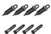 | Owner's manualInstallation manual | |
| S3 |  |  | ||
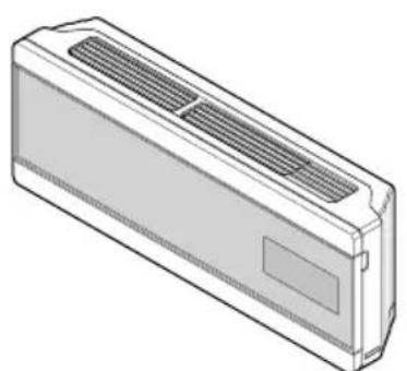


Safety Precautions
To prevent injury to the user or other people and property damage, the following instructions must be followed.
■ Be sure to read before installing the air conditioner.
■ Be sure to observe the cautions specified here as they include important items related to safety.
■ Incorrect operation due to ignoring instruction will cause harm or damage. The seriousness is classified by the following indications.

WARNING
This symbol indicates the possibility of death or serious injury.

CAUTION
This symbol indicates the possibility of injury or damage to properties only.
■ Meanings of symbols used in this manual are as shown below.


Be sure not to do.
Be sure to follow the instruction.

WARNING
■ Installation
Do not use a defective or underrated circuit breaker. Use this appliance on a dedicated circuit.
• There is risk of fire or electric shock.
For electrical work, contact the dealer, seller, a qualified electrician, or an Authorized Service Center.
- Do not disassemble or repair the product. There is risk of fire or electric shock.
Always ground the product.
- There is risk of fire or electric shock.
Install the panel and the cover of control box securely.
• There is risk of fire or electric shock.
Always install a dedicated circuit and breaker.
- Improper wiring or installation may cause fire or electric shock.
Use the correctly rated break-er or fuse.
• There is risk of fire or electric shock.
Do not modify or extend the power cable.
- There is risk of fire or electric shock.
Do not let the air conditioner run for a long time when the humidity is very high and a door or a window is left open.
- Moisture may condense and wet or damage furniture.
Be cautious when unpacking and installing the product.
- Sharp edges could cause injury. Be especially careful of the case edges and the fins on the condenser and evaporator.
For installation, always contact the dealer or an Authorized Service Center.
- There is risk of fire, electric shock, explosion, or injury.
Do not install the product on a defective installation stand.
- It may cause injury, accident, or damage to the product.
Be sure the installation area does not deteriorate with age.
- If the base collapses, the air conditioner could fall with it, causing property damage, product failure, and personal injury.
Use a vacuum pump or Inert (nitrogen) gas when doing leakage test or air purge. Do not compress air or Oxygen and Do not use Flammable gases. Otherwise, it may cause fire or explosion.
- There is the risk of death, injury, fire or explosion.
Operation
Do not store or use flammable gas or combustibles near the product.
- There is risk of fire or failure of product.
CAUTION
■ Installation
Always check for gas (refrigerant) leakage after installation or repair of product.
- Low refrigerant levels may cause failure of product.
Install the drain hose to ensure that water is drained away properly.
• A bad connection may cause water leakage.
Keep level even when installing the product.
• To avoid vibration or water leakage.
Do not install the product where the noise or hot air from the outdoor unit could damage the neighborhoods.
• It may cause a problem for your neighbors.
Use two or more people to lift and transport the product.
- Avoid personal injury.
Do not install the product where it will be exposed to sea wind (salt spray) directly.
- It may cause corrosion on the product. Corrosion, particularly on the condenser and evaporator fins, could cause product malfunction or inefficient operation.
If you eat the liquid from the batteries, brush your teeth and see doctor. Do not use the remote if the batteries have leaked.
• The chemicals in batteries could cause burns or other health hazards.
Installation
Read completely, then follow step by step.
Selection of the best location
- There should not be any heat source or steam near the unit.
- There should not be any obstacles to prevent the air circulation.
- A place where air circulation in the room will be good.
• A place where drainage can be easily obtained. - A place where noise prevention is taken into consideration.
- Do not install the unit near the door way.
- Ensure the spaces indicated by arrows from the wall, ceiling, fence, or other obstacles.
The mounting wall should be strong and solid enough to protect it from the vibration.
Mount the installation plate on the wall with four Type "A" screws.
(If mounting the unit on the concrete wall, consider using anchor bolts.)
• Always mount the Installation plate horizontally by aligning the marking-off line by means of the thread and a level.


The lower left and the right side of Installation Plate
S3 chassis SE chassis


CAUTION : In case that the unit is installed near the sea, the installation parts may be corroded by salt. The installation parts (and the unit) should be taken appropriate anti-corrosion measures.
Drill a Hole in the Wall
- Drill the piping hole with a 70mm hole core drill. Drill the piping hole at either the right or the left with the hole slightly slanted to the outdoor side.

Piping Method
■ Preparing the indoor unit's piping and drain hose for installation through the wall.
■ Remove the plastic tubing retainer(see illustration below) and pull the tubing and drain hose away from chassis.
■ Replace the plastic tubing holder in the original position.

For right rear piping
- Route the indoor tubing and the drain hose in the direction of rear left.

- Insert the connecting cable into the indoor unit from the outdoor unit through the piping hole.
■ Do not connect the cable to the indoor unit.
■ Make a small loop with the cable for easy connection later.
- Tape the tubing, drain hose and the connecting cable. Be sure that the drain hose is located at the lowest side of the bundle. Locating at the upper side can cause drain pan to overflow inside the unit.

NOTICE : If the drain hose is routed inside the room, insulate the hose with an insulation material* so that dripping from "sweating"(condensation) will not damage furniture or floors.
*Foamed polyethylene or equivalent is recommended.
- Indoor unit installation
■ Hook the indoor unit onto the upper portion of the installation plate.(Engage the two hooks of the rear top of the indoor unit with the upper edge of the installation plate.) Ensure that the hooks are properly seated on the installation plate by moving it left and right.
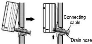
Press the lower left and right sides of the unit against the installation plate until the hooks engage into their slots(clicking sound).
- Connecting the pipings to the indoor unit and drain hose to drain pipe.
■ Align the center of the pipings and sufficiently tighten the flare nut by hand.

■ Tighten the flare nut with a wrench.

| Pipe Size[Torque] | |
| GAS LIQUID | |
| ∅12.7[5.5kgf·m] ∅6.35[1.8kgf ·m] | |
| ∅15.88[6.6kgf·m] ∅9.52[4.2kgf ·m] | |
■ Mount the clamp on the boss with a type "B" screw.(optional)
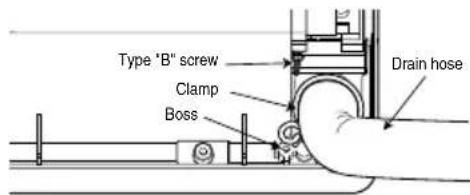
■ When extending the drain hose at the indoor unit, install the drain pipe.

- Wrap the insulation material around the connecting portion.
■ Overlap the connection pipe insulation material and the indoor unit pipe insulation material. Bind them together with vinyl tape so that there is no gap.

■ Wrap the area which accommodates the rear piping housing section with vinyl tape.

■ Bundle the piping and drain hose together by wrapping them with vinyl tape over the range within which they fit into the rear piping housing section.

CAUTION
If the split type Indoor unit is installed in a wall having hole or opening near by or back side of the unit, then the air from other side of the wall can come inside the condition space through that hole/opening. That air can cause unwanted dew/water droplet formation when it comes in contact with body of the indoor unit. So all hole or opening on the wall must be blocked very well to avoid water dropping from the body of the unit.
For left rear piping
- Route the indoor tubing and the drain hose to the required piping hole position.

- Insert the piping, drain hose and the connecting cable into the piping hole.

- Insert the connecting cable into the indoor unit.
■ Don't connect the cable to the indoor unit.
■ Make a small loop with the cable for easy connection later.
- Tape the drain hose and the connecting cable.
- Connecting cable

- Indoor unit installation
■ Hang the indoor unit from the hooks at the top of the installation plate.
■ Insert the spacer etc. between the indoor unit and the installation plate and separate the bottom of the indoor unit from the wall.

- Connecting the pipings to the indoor unit and the drain hose to drain pipe.
■ Align the center of the pipings and sufficiently tighten the flare nut by hand.
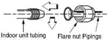
■ Tighten the flare nut with a wrench.

| Pipe Size[Torque] | |
| GAS LIQUID | |
| ∅12.7[5.5kgf·m] ∅6.35 | [1.8kgf m] |
| ∅15.88[6.6kgf·m] ∅9.52 | [4.2kgf m] |
■ When extending the drain hose at the indoor unit, install the drain pipe.
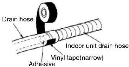
- Wrap the insulation material around the connecting portion.
■ Overlap the connection pipe heat insulation and the indoor unit pipe heat insulation material. Bind them together with vinyl tape so that there is no gap.

■ Wrap the area which accommodates the rear piping housing section with vinyl tape.

■ Bundle the piping and drain hose together by wrapping them with cloth tape over the range within which they fit into the rear piping housing section.

- Reroute the pipings and the drain hose across the back of the chassis.

- Set the pipings and the drain hose to the back of the chassis with the tubing holder.
■ Hook the edge of tubing holder to tap on chassis and push the bottom of tubing holder to be engaged at the bottom of chassis.

- Indoor unit installation
■ Remove the spacer.
■ Ensure that the hooks are properly seated on the installation plate by moving it left and right.
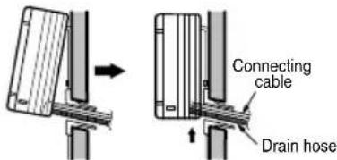
Press the lower left and right sides of the unit against the installation plate until the hooks engage into their slots(clicking sound).
▲ CAUTION
If the split type Indoor unit is installed in a wall having hole or opening near by or back side of the unit, then the air from other side of the wall can come inside the condition space through that hole/ opening. That air can cause unwanted dew/ water droplet formation when it comes in contact with body of the indoor unit. So all hole or opening on the wall must be blocked very well to avoid water dropping from the body of the unit.

CAUTION
Installation Information (For left piping)
• Good case
For left piping. Follow the instruction below.
■ Press on the upper side of clamp. (A)
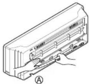
■ Unfold the tubing to downward slowly. (®)


CAUTION
- Bad case
■ Following bending type from right to left could cause problem of pipe damage.

Drain Piping
- To remove the front panel from the indoor unit, remove the front panel from the indoor unit cabinet.
■ Set the air direction louvers up-and-down to the position(horizontally) by hand.
■ Remove the securing screws that retain the front panel. Pull the lower left and right sides of the grille toward you and lift it off.

- To check the drainage.
■ Pour a glass of water on the evaporator.
■ Ensure the water flows through the drain hose of the indoor unit without any leakage and goes out the drain exit.

■ The drain hose should point downward for easy drain flow.

■ Do not make drain piping.

Wiring Connection
Connect the wires to the terminals on the control board individually according to the outdoor unit connection.
- Ensure that the color of the wires of outdoor unit and the terminal No. are the same as those of indoor unit respectively.

![graph TD A["INDOOR POWER INPUT"] --> B["Terminal Block Indoor"] B --> C["Outdoor unit"] C --> D["Central controller"] D --> E["Outdoor unit"] style A fill:#f9f,stroke:#333 style B fill:#ccf,stroke:#333 style C fill:#cfc,stroke:#333 style D fill:#fcc,stroke:#333 style E fill:#ffc,stroke:#333](/content/2026/08/1561992/images/d68cc68ddfd3ddd1bf6e68e1483136acabbcb0ef5e4b7773316f9b6eb44a34ab.jpg)

CAUTION : The Power cord connected to the unit should be selected according to the following specifications.

CAUTION:
After the confirmation of the above conditions, prepare the wiring as follows:
1) Never fail to have an individual power circuit specifically for the air conditioner. As for the method of wiring, be guided by the circuit diagram posted on the inside of control cover.
2) The screw which fasten the wiring in the casing of electrical fittings are liable to come loose from vibrations to which the unit is subjected during the course of transportation. Check them and make sure that they are all tightly fastened. (If they are loose, it could cause burn-out of the wires.)
3) Specification of power source.
4) Confirm that electrical capacity is sufficient.
5) See to that the starting voltage is maintained at more than 90 percent of the rated voltage marked on the name plate.
6) Confirm that the cable thickness is as specified in the power source specification. (Particularly note the relation between cable length and thickness.)
7) In a wet or moist area, always install an earth leakage circuit breaker.
8) The following would be caused by voltage drop.
- Vibration of a magnetic switch, which will damage the contact point, fuse breaking, disturbance of the normal function of the overload.
9) The means for disconnection from a power supply shall be incorporated in the fixed wiring and have an air gap contact separation of at least 3mm in each active(phase) conductors.
Installation of Wireless Remote Controller
How to insert the Batteries
- Remove the battery cover by pulling it according to the arrow direction.
- Insert new batteries making sure that the (+) and (-) of battery are installed correctly.
- Reattach the cover by sliding it back into position.
NOTE
- Always use/replace both batteries of same type.
- If the system is not to be used for a long time, remove the batteries to save their working life.
- If the display screen of remote controller starts, fading replace both of the batteries.

Wireless Remote Controller Maintenance
- Choose a suitable place where its safe & easy to reach.
- Fix the holder to wall etc with the supplied screws firmly.
- Slide the remote controller inside the holder.

NOTE
- Remote controller should never be exposed to direct sunlight.
- Signal transmitter & receiver should always be clean for proper communication. Use a soft cloth to clean them.
- In case some other appliances also get operated with remote control, change their position or consult your serviceman.

Operating Method
- The signal receiver is inside the unit.
- Aim the remote controller towards the unit to operate it. There should not be any blockage in between.
Installation of Wired Remote Controller
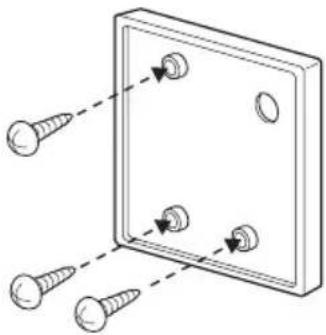
- Please fix tightly using provided screw after placing remote controller setup board on the place where you like to setup.
- Please set it up not to bend because poor setup could take place if setup board bends. Please set up remote controller board fit to the reclamation box if there is a reclamation box.
- Can set up Wired remote controller cable into three directions.
- Setup direction: the surface of wall reclamation, upper, right - If setting up remote controller cable into upper and right side, please set up after removing remote controller cable guide groove.
* Remove guide groove with long nose.
① Reclamation to the surface of the wall
② Upper part guide groove
③ Right part guide groove

- Please fix remote controller upper part into the setup board attached to the surface of the wall, as the picture below, and then, connect with setup board by pressing lower part.
- Please connect not to make a gap at the remote controller and setup board's upper and lower, right and left part.
When separating remote controller from setup board, as the picture below, after inserting into the lower separating hole using screw driver and then, spinning clockwise, remote controller is separated.
- There are two separating holes. Please individually separate one at a time.
- Please be careful not to damage the inside components when separating.
![graph LR A["Wall Side"] --> B["<Connecting order>"] B --> C["Wall Side"]](/content/2026/08/1561992/images/d4fc25bffda0ce40516fa0b6061cac4fe17e904284222c87ca3e53b491a838ef.jpg)

- Please connect indoor unit and remote controller using connection cable.
![graph LR A["Outdoor Monitoring System"] --> B["Connecting Cable"] B --> C["Indoor Unit Side"] D["Please check if connector is normally connected."] --> E["Connector with connection cable"]](/content/2026/08/1561992/images/6ca8ffbe7c57bc0794e59e3e5fe92d4b0deb949138c4b14fcac24cbe5066ddd7.jpg)
- Please use extension cable if the distance between wired remote controller and indoor unit is more than 10m.

CAUTION
When installing the wired remote controller, do not bury it in the wall.
(It can cause damage in the temperature sensor.)
Do not install the cable to be 50m or above.
(It can cause communication error.)
- When installing the extension cable, check the connecting direction of the connector of the remote controller side and the product side for correct installation.
- If you install the extension cable in the opposite direction, the connector will not be connected.
- Specification of extension cable: 2547 1007 22# 2 core 3 shield 5 or above.
WIRED REMOTE CONTROLLER INSTALLATION
- Since the room temperature sensor is in the remote controller, the remote controller box should be installed in a place away from direct sunlight, high humidity and direct supply of cold air to maintain proper space temperature. Install the remote controller about 5ft(1.5m) above the floor in an area with good air circulation at an average temperature.
Do not install the remote controller where it can be affected by:
- Drafts, or dead spots behind doors and in corners.
- Hot or cold air from ducts.
- Radiant heat from sun or appliances.
- Concealed pipes and chimneys.
- Uncontrolled areas such as an outside wall behind the remote controller.
- This remote controller is equipped with a seven segment LED. display. For proper display of the remote controller LED's, the remote controller should be installed properly as shown in Fig.1.
(The standard height is 1.2\~1.5 m from floor level.)

Fig.1 Typical locations for remote controller
Name and function of wired remote controller(Accessory)

Please attach the inform label inside of the door. Please choose proper language depend on your country.
- Operation indication screen
- Set temperature button
- It will set not room temperature but outlet air temperature.
- Fan speed button
• Fan Speed have 3 Steps.
• Middle and Low step is same
-
ON/OFF button
-
Opration mode selection button
- Wireless remote controller receiver
• Some products don't receive the wireless signals.
- Air flow button
- Subfunction button
-
Function setting button
-
Ventilation button
-
Reservation
- Up,down,left,right button
• To check the indoor temperature, press 📋 button.
-
Room temperature button
-
Displays only the room temperature of the remote controller perception.
• There is no control of room temperature. -
In case of fresh air intake unit, displays only the temperature around remote controller.
-
Setting/Cancel button
-
Exit button
* Some functions may not be operated and displayed depending on the product type.
* It will display strange value to the room temperature if wired remote controller is not connected.
Model : PQRCVSL0 (Black Color)
PQRCVSL0QW (White Color)
Group Control Setting
CAUTION
Installer setting mode is to set the detail function of the remote controller.
If the installer setting mode is not set correctly, it can cause problems to the product, user injury or property damage. This must be set by an certificated installer, and any installation or change that is carried out by a non-certificated person should be responsible for the results. In this case, free service cannot be provided.
![00 FUNC. VANE ANGLE PLASMA ° TEMP. JET COOL ✓ FAN SPEED SWING SWING ROOM TEMP TIMER °C/15SEC SLEEP ON OFF ✓ SET CLEAR LIGHT TIME[3SEC] LG](/content/2026/08/1561992/images/1b11b4ae47c83400cbd5c89ec43b6d3631cf50ef475bad42388dba9622e7643d.jpg)
1 When JET COOL button pressed, press RESET button


2 By using the TEMPERATURE SETTING button, set function code and setting value. (Please refer the Installer Setting Code Table.)
![graph LR A["00"] --> B["Function Code"] A --> C["Setting Code"] B --> D["△"] C --> E["▽"] D --> F["TEMP."] E --> G["▽"]](/content/2026/08/1561992/images/fee690fed32aff9d05a1bb1de01a06bc76e6ab5ae2fbf930b0d118d607e4feca.jpg)
3 Press the ON/OFF button toward the indoor unit 1 time.

4 Reset the remote controller to use the general operation mode.

Refer to the Installer Setting Code Table on the next page.
Installer Setting Code Table
| No. | Function Function Code Setting Value Remote Controller LCD | |||
| 2 | Group Control | 2 | 0 : Set to Master | 20 |
| 1 : Set to Slave | 21 | |||
| 2 : Check Master/Slave | 22 | |||
1. Group Control 1
■ Wired remote controller 1 + Indoor units
![graph TD A["Master"] --> B["Display Error Message"] C["Slave"] --> D["Display Error Message"] E["Slave"] --> F["Display Error Message"] G["Master"] --> H["Display Error Message"] I["Slave"] --> J["Display Error Message"] K["Master"] --> L["Display Error Message"] M["Slave"] --> N["Display Error Mess…](/content/2026/08/1561992/images/b91d3de6a3c17eda5f4419c4b923231798a2768d1ea925b9a469fdf3049109c9.jpg)
- It is possible to 16 indoor units(Max) by one wired remote controller.
Set only one indoor unit to Master, set the others to Slave.
- It is possible to connect with every type of indoor units.
- It is possible to use wireless remote controller at the same time.
-
It is possible to connect with Dry Contact and Central controller at the same time.
-
The Master indoor unit is possible to recognize Dry Contact and Central Controller only.
- In case of Central controller and Group controller at the same time, it is possible to connect standard 2series indoor units or later since Feb. 2009.
- In case of Central controller setting, the Central controller can control indoor units after setting only the address of master indoor unit.
- Slave indoor unit will be operated like master indoor unit.
- Slave indoor unit can not be individually controlled by Central controller.
-
Some remote controller can't perform with Dry Contact and Central controller at the same time. So contact us further information about it.
-
In case of any error occurs at indoor unit, display on the wired remote controller.
Exception of the error indoor unit, an individual indoor unit control possibility.
-
In case of Group Control, it is possible to use following functions.
-
Selection of operation options (operation/stop/mode/set temperature)
- Control of flow rate (High/Middle/Low)
- It is not possible at some functions.
* Indoor units be set possible using a wireless remote controller.
This indoor unit be set possible using a wireless remote controller for setting group control.
(type : Wall Mounted, ART COOL Gallery, ART COOL Mirror)
* It is possible to connect indoor units since Feb. 2009. In the other cases, please contact LGE.
* It can be the cause of malfunctions when there is no setting of master and slave.
2. Group Control 2
![graph TD A["Master"] -->|GND| B["Slave"] C["Slave"] -->|Signal| B D["Master"] -->|Display Error Message| B E["Slave"] -->|12V| B F["Master"] -->|Don't connect serial 12V line| B G["Slave"] -->|12V| B H["Master"] --> I["Display Error Message"] J["Slave"] --> I K["Master"] --> L["Display Error Message…](/content/2026/08/1561992/images/0ea791a8e7bf78e2b711e040e4d1a9d278a6f09b2efb8fa57a85cbcc07227280.jpg)
* It is possible to control N indoor units by wired remote controller M units. (M + N ≤ 17 Units)
Set only one indoor unit to Master, set the others to Slave.
Set only one wired remote controller to Master, set the others to Slave.
Other than those, it is same with the Group Control 1.
3. Group Control 3
■ Mixture connection with indoor units and Fresh Air Intake Unit
![graph TD A["Master"] --> B["FAU Master"] B --> C["Display Error Message"] C --> D["Master"] D --> E["FAU Slave"] E --> F["Master"] F --> G["Slave"] G --> H["Master"] H --> I["Display Error Message"] I --> J["Master"] J --> K["FAU Master"] K --> L["Display Error Message"] L --> M["Master"] M --> N["F…](/content/2026/08/1561992/images/5ae20f4f3c5173faf7de5481db394cbae9b62bc89cb1d801aa537b7058c5ac6c.jpg)
* In case of connecting with standard indoor unit and Fresh Intake Unit, separate Fresh Air Intake Unit with standard units. (Because setting temperature are different.)
* Other than those, it is same with Group Control 1.
![graph TD A["Power Supply Unit"] --> B["FAU"] B --> C["Central Circle"] C --> D["Standard"] C --> E["Standard"] C --> F["Standard"] C --> G["Standard"] C --> H["Standard"] C --> I["Standard"] C --> J["Standard"] C --> K["Standard"] C --> L["Standard"]](/content/2026/08/1561992/images/d28f3da887972ec6a58fedb0f6373eba172af25456213c0e941ce5fd83f08023.jpg)
![graph TD A["Power Supply Unit"] --> B["FAU"] B --> C["Standard"] B --> D["Standard"] C --> E["No Prohibited Symbol"] D --> E E --> F["Output"]](/content/2026/08/1561992/images/b5ad0986fbd3c35a1724c2fca88779d99e710f17c3622b6c94f3da6b7acdac11.jpg)
* FAU : Fresh Air Intake Unit Standard: Standard Indoor Unit
4. 2 Remote Control
■ Wired remote controller 2 + Indoor unit 1
![graph TD A["Master"] --> B["Display Error Message"] B --> C["Master"] B --> D["Slave"] E["LGAP Network System"] --> F["Master"] F --> G["Slave"] style A fill:#f9f,stroke:#333 style B fill:#ccf,stroke:#333 style C fill:#cfc,stroke:#333 style D fill:#fcc,stroke:#333](/content/2026/08/1561992/images/608b283a6b026761ccc25cea341a70b8b4c0b53eae37c9c96b8bb8526f7d64d6.jpg)
- It is possible to connect two wired remote controllers with one indoor unit.
- Every types of indoor unit is possible to connect two remote controller.
- It is possible to use wireless remote controller at the same time.
- It is possible to connect with Dry Contact and Central controller at the same time.
- In case of any error occurs at indoor unit, display on the wired remote controller.
- There isn't limits of indoor unit function.
* Maximum 2wired remote controllers can be connected with 1 indoor unit.
5. Accessories for group control setting
It is possible to set group control by using below accessories.
| Indoor unit 2 EA +Wired remote controller | Indoor unit 1 EA +Wired remote controller 2EA |
※ PZCWRCG3 cable used for connection | ※ PZCWRC2 cable used for connection |

LG
Life's Good



- TABLE OF CONTENTS
- INSTALLATION REQUIREMENTS
- REQUIRED PARTS REQUIRED TOOLS
- INSTALLATION PARTS ....3
- SAFETY PRECAUTIONS......4
- INSTALLATION
- INSTALLATION PARTS
- SAFETY PRECAUTIONS
- DO NOT MODIFY OR EXTEND THE POWER CABLE
- DO NOT LET THE AIR CONDITIONER RUN FOR A LONG TIME WHEN THE HUMIDITY IS VERY HIGH AND A DOOR OR A WINDOW IS LEFT OPEN
- BE CAUTIOUS WHEN UNPACKING AND INSTALLING THE PRODUCT
- FOR INSTALLATION, ALWAYS CONTACT THE DEALER OR AN AUTHORIZED SERVICE CENTER
- DO NOT INSTALL THE PRODUCT ON A DEFECTIVE INSTALLATION STAND
- BE SURE THE INSTALLATION AREA DOES NOT DETERIORATE WITH AGE
- OPERATION
- CAUTION
- ALWAYS CHECK FOR GAS (REFRIGERANT) LEAKAGE AFTER INSTALLATION OR REPAIR OF PRODUCT
- INSTALL THE DRAIN HOSE TO ENSURE THAT WATER IS DRAINED AWAY PROPERLY
- KEEP LEVEL EVEN WHEN INSTALLING THE PRODUCT
- DO NOT INSTALL THE PRODUCT WHERE THE NOISE OR HOT AIR FROM THE OUTDOOR UNIT COULD DAMAGE THE NEIGHBORHOODS
- USE TWO OR MORE PEOPLE TO LIFT AND TRANSPORT THE PRODUCT
- DO NOT INSTALL THE PRODUCT WHERE IT WILL BE EXPOSED TO SEA WIND (SALT SPRAY) DIRECTLY
- IF YOU EAT THE LIQUID FROM THE BATTERIES, BRUSH YOUR TEETH AND SEE DOCTOR. DO NOT USE THE REMOTE IF THE BATTERIES HAVE LEAKED
- SELECTION OF THE BEST LOCATION
- MOUNT THE INSTALLATION PLATE ON THE WALL WITH FOUR TYPE "A" SCREWS
- THE LOWER LEFT AND THE RIGHT SIDE OF INSTALLATION PLATE
- DRILL A HOLE IN THE WALL
- PIPING METHOD
- FOR RIGHT REAR PIPING
- FOR LEFT REAR PIPING
- ▲ CAUTION
- BAD CASE
- DRAIN PIPING
- WIRING CONNECTION
- INSTALLATION OF WIRELESS REMOTE CONTROLLER
- HOW TO INSERT THE BATTERIES
- NOTE
- WIRELESS REMOTE CONTROLLER MAINTENANCE
- OPERATING METHOD
- INSTALLATION OF WIRED REMOTE CONTROLLER
- WIRED REMOTE CONTROLLER INSTALLATION
- DO NOT INSTALL THE REMOTE CONTROLLER WHERE IT CAN BE AFFECTED BY
- NAME AND FUNCTION OF WIRED REMOTE CONTROLLER(ACCESSORY)
- GROUP CONTROL SETTING
- GROUP CONTROL 1
- GROUP CONTROL 2
- GROUP CONTROL 3
- 2 REMOTE CONTROL
- ACCESSORIES FOR GROUP CONTROL SETTING
Brand : LG
Model : ARNU24GS3M2
Category : Water pump