CMHD7352N-28 - Surveillance Camera LTS - Free user manual and instructions
Find the device manual for free CMHD7352N-28 LTS in PDF.


| Product Type | Security Camera |
| Model | CMHD7352N-28 |
| Brand | LTS |
| Resolution | 5MP (2592x1944) at 20fps |
| Lens | 2.8mm fixed lens |
| Night Vision | Up to 30m with IR LEDs |
| Day/Night Function | Auto-switching with ICR filter |
| Compression | H.265+ / H.265 / H.264+ / H.264 |
| Power Supply | 12V DC, PoE (802.3af) |
| Power Consumption | Max 10W |
| Dimensions | Φ 110mm x 95mm |
| Weight | 0.45 kg |
| Protection Rating | IP67 (weatherproof) |
| Operating Temperature | -30°C to +60°C |
| Motion Detection | Yes, with sensitivity adjustment |
| Audio | One-way audio (built-in mic) |
| Alarm I/O | 1 input, 1 output |
| Storage | MicroSD card up to 256GB, NVR |
| Network | 10/100Mbps Ethernet, ONVIF compatible |
| Maintenance | Clean lens with dry cloth; keep firmware updated |
| Safety | Do not disassemble; use certified power adapter |
| Spare Parts | Contact LTS support for replacement |
| Repairability | Not user-serviceable; seek professional service |
| General Info | Compatible with LTS NVR and third-party via ONVIF |
Frequently Asked Questions - CMHD7352N-28 LTS
User questions about CMHD7352N-28 LTS
0 question about this device. Answer the ones you know or ask your own.
Ask a new question about this device
Download the instructions for your Surveillance Camera in PDF format for free! Find your manual CMHD7352N-28 - LTS and take your electronic device back in hand. On this page are published all the documents necessary for the use of your device. CMHD7352N-28 by LTS.
USER MANUAL CMHD7352N-28 LTS
5MP Series Bullet & Dome Camera
User Manual
User Manual
Thank you for purchasing our product. If there are any quesons, or requests, do not hesitate to contact the dealer.
This manual may contain several technical mistakes or prinng errors, and the content is subject to change without noce. The updates will be added to the new version of this manual. We will readily improve or update the products or procedures described in the manual.
Regulatory Informaon
FCC Informaon
Please take aenon that changes or modicaon not expressly approved by the party responsible for compliance could void the user's authority to operate the equipment.
FCC compliance: This equipment has been tested and found to comply with the limits for a Class A digital device, pursuant to part 15 of the FCC Rules. These limits are designed to provide reasonable protecon against harmful interference when the equipment is operated in a commercial environment. This equipment generates, uses, and can radiate radio frequency energy and, if not installed and used in accordance with the instrucon manual, may cause harmful interference to radio communicaons. Operaon of this equipment in a residential area is likely to cause harmful interference in which case the user will be required to correct the interference at his own expense.
FCC Conditions
This device complies with part 15 of the FCC Rules. Operaon is subject to the following two conditions:
- This device may not cause harmful interference.
- This device must accept any interference received, including interference that may cause undesired operaon.
EU Conformity Statement

This product and - if applicable - the supplied accessories too are marked with "CE" and comply therefore with the applicable harmonized European
standards listed under the Low Voltage Direcve 2014/35/EU, the EMC Direcve 2014/30/EU.

2012/19/EU (WEEE direcve): Products marked with this symbol cannot be disposed of as unsorted municipal waste in the European Union. For proper recycling, return this product to your local supplier upon the purchase of equivalent new
equipment, or dispose of it at designated collecon points. For more informaon see: www.recyclethis.info. 2006/66/EC (baery direcve): This product contains a

baery that cannot be disposed of as unsorted municipal waste in the European Union. See the product documentaon for specic baery informaon. The baery is marked with this symbol, which may
include leering to indicate cadmium (Cd), lead (Pb), or mercury (Hg). For proper recycling, return the baery to your supplier or to a designated collecon point. For more informaon, see: www.recyclethis.info.
Industry Canada ICES-003 Compliance
This device meets the CAN ICES-3 (A)/NMB-3(A) standards requirements.
Warning
This is a class A product. In a domesc environment this product may cause radio interference in which case the user may be required to take adequate measures.
Safety Instrucon
These instrucons are intended to ensure that user can use the product correctly to avoid danger or property loss.
The precauon measure is divided into "Warnings" and "Cauons".
Warnings: Serious injury or death may occur if any of the warnings are neglected.
Cauons: Injury or equipment damage may occur if any of the cauons are neglected.
 |  |
| Warnings Follow these safeguards to prevent serious injury or death. | Cauons Follow these precautions to prevent potential injury or material damage. |

Warnings
- In the use of the device, you must be in strict compliance with the electrical safety regulations of the naon and region.
- Input voltage should meet both the SELV (Safety Extra Low Voltage) and the Limited Power Source with 12 VDC according to the IEC60950-1 standard. Refer to technical speciaons for detailed informaon.
- Do not connect mulple devices to one power adapter to avoid over-heang or a re hazard caused by overload.
- Make sure that the plug is rmly connected to the power socket.
- Make sure that the device is rmly fixed if wall mounng or ceiling mounng is adopted.
- If smoke, odor or noise rise from the device, turn o the power at once and unplug the power cord, and then contact the service center.
- Never attempt to disassemble the camera by unprofessional personal.

Cauons
- Do not drop the camera or subject it to physical shock.
- Do not touch senor modules with ngers.
- Do not place the camera in extremely hot, cold (the operang temperature shall be -40° C to 60° C), dusty or damp locaons, and do not expose it to high electromagnetic radiation.
- If cleaning is necessary, use clean cloth with a bit of ethanol and wipe it gently.
- Do not aim the camera at the sun or extra bright places.
- The sensor may be burned out by a laser beam, so when any laser equipment is in using, make sure that the surface of sensor will not be exposed to the laser beam.
- Do not expose the device to high electromagnetic radiaon or extremely hot, cold, dusty or damp environment.
-
To avoid heat accumulation, good ventilation is required for the operang environment.
-
Keep the camera away from liquid while in use for non-water-proof device.
- While in delivery, the camera shall be packed in its original packing, or packing of the same texture.
Mark Descripon
Table 0-1 Mark Descripon
| Mark | Descripon |
| --- | DC Voltage |
1 Introducon
1.1 Product Features
The main features are as follows:
• High performance CMOS sensor
- OSD menu with congorable parameters
- Smart IR
• 3-Axis Adjustment
1.2 Overview
1.2.1 Overview of Type I Camera

Figure 1-1 Overview of Type I Camera
Note:
Press and hold the switch buon for 5 seconds to switch the video output. Four kinds of video outputs are available: TVI, AHD, CVI, and CVBS.
1.2.2 Overview of Type II Camera

Figure 1-2 Overview of Type II Camera
Note:
Press and hold the switch buon for 5 seconds to switch the video output. Four kinds of video outputs are available: TVI, AHD, CVI, and CVBS.
1.2.3 Overview of Type III Camera

Figure 1-3 Overview of Type III Camera
Note:
Press and hold the switch buon for 5 seconds to switch the video output. Four kinds of video outputs are available: TVI, AHD, CVI, and CVBS.
1.2.4 Overview of Type IV Camera

Figure 1-4 Overview of Type III Camera
Note:
Press and hold the switch buon for 5 seconds to switch the video output. Four kinds of video outputs are available: TVI, AHD, CVI, and CVBS.
Before you start:
- Make sure that the device in the package is in good condition and all the assembly parts are included.
- Make sure that all the related equipment is power-o during the installaon.
- Check the specification of the products for the installaon environment.
- Check whether the power supply is matched with your power output to avoid the damage.
- Make sure the wall is strong enough to withstand three mes the weight of the camera and the mount.
- If the wall is cement, insert expansion bolts before installing the camera. If the wall is wooden, use self-tapping screws to secure the camera.
- If the product does not funcon properly, contact your dealer or the nearest service center. Do NOT disassemble the camera for repair or maintenance by yourself.
2.1 Ceiling/Wall Mounng of Type I Camera
Before you start:
The ceiling moung and the wall moung are similar. Following takes ceiling moung as an example.
Steps:
- Paste the drill template (supplied) to the place where you want to install the camera.
- Drill the screw holes, and the cable hole (oponal) on ceiling according to the drill template.
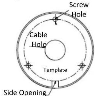
Figure 2-1 Drill Template
Note:
Drill the cable hole, when adopng the ceiling outlet to route the cable.
- Route cables through the cable hole or the side opening.
- Aach the bracket to the ceiling and secure the camera with supplied screws. For cement ceiling, you need to mount expansion bolts at rst.

Figure 2-2 Aach the Camera to the Ceiling
Note:
The supplied screw package contains self-tapping screws, and expansion bolts.
- Connect the corresponding power cord, and video cable.
- Power on the camera to check whether the image on the monitor is goen from the opmum angle. If
not, adjust the camera according to the gure below.
![Rotaon Posion [0° to 360°] Pan Posion [0° to 360°] Bracket Adjuusng Screw Tilt Posion [0° to 90°]](/content/2026/07/1527673/images/edc372a9a397a7905ff090048fcd173560e0bb05443494539b42437158985d2a.jpg)
Figure 2-3 3-Axis Adjustment
2.2 Ceiling/Wall Mounng of Type II Camera
Before you start:
The ceiling moung and the wall moung are similar. Following takes ceiling moung as an example.
Steps:
- Paste the drill template (supplied) to the place where you want to install the camera.
- Drill the screw holes according to the drill template, and the cable hole (oponal) on the ceiling.

Figure 2-4 Drill Template
Note:
Drill the cable hole in the center of the drill template, when adoping ceiling outlet to route the cable.
- Route cables through the cable hole or the side opening.
- Aach the camera to the ceiling with supplied screws.

Figure 2-5 Aach the Camera to the Ceiling
Note:
- The supplied screw package contains self-tapping screws, and expansion bolts.
-
For cement wall/ceiling, expansion bolts are required to x the camera. For wooden wall/ceiling, self-tapping screws are required.
-
Connect the corresponding power cord, and video cable.
-
Power on the camera to check if the image on the monitor is goen from the opmum angle. If not, adjust the camera according to the gure below.
![Rotaon Posion [0° to 360°] Pan Posion [0° to 360°] Trim Ring Tilt Posion [0° to 180°] Screw A Screw B](/content/2026/07/1527673/images/916452d46dac7a33c9185c2856c2a5dfdff65378ad3e1c2c934f37245c58dae9.jpg)
Figure 2-6 3-Axis Adjustment
1). Loosen the trim ring to adjust the pan posion [0° to 360°].
2). Loosen screw A to adjust the lt posion [0° to 180°].
3). Loosen screw B to adjust the rotaon posion [0° to 360°].
2.3 Ceiling Mounng of Type III Camera
Before you start:
The ceiling moung and the wall moung are similar. Following takes ceiling moung as an example.
Steps:
- Paste the drill template (supplied) to the place where you want to install the camera.
- Drill the screw holes and cable hole (oponal) on the ceiling according to the drill template.

Figure 2-7 Drill Template
Note:
Cable hole is required, when adopng the ceiling outlet to route cables.
- Loosen the set screws to remove the bubble.

Figure 2-8 Remove the Bubble
Note:
- You do not have to loosen those screws enrely.
- Remove the bubble with care. The bubble is connected to the moung base with a safety rope.
- Route the cables through the cable hole, or the side opening.
- Aach the moung base to the ceiling with supplied screws.

Figure 2-9 Aach the Mounng Base
-
Connect the corresponding cables, such as power cord, and video cable.
-
Power on the camera to check whether the image on the monitor is goen from the opmum angle. If not, loosen the lt adjusng screw to adjust the angle.
![Pan Posion [0° to 355°] Tilt Adjuusng Screw Tilt Posion [0° to 355°] Rotaon Posion](/content/2026/07/1527673/images/42fcf2254f2dbc8b7538e42e24d7fe790626fb2ce8e0f3c992f47c7babbb4e3c.jpg)
Figure 2-10 3-Axis Adjustment
- Install the bubble back and ghten screws to nish the installaon.

Figure 2-11 Install the Bubble Back
2.4 Ceiling Mounng of Type IV Camera
Before you start:
The ceiling moung and the wall moung are similar. Following takes ceiling moung as an example.
Steps:
- Align the snap joint, and then insert the screw driver into the snap joint.

Figure 2-12 Disassemble the Camera
- Pry the bubble by anclockwise rotate the screw driver and take o the black liner.

Figure 2-13 Remove the Bubble and the Black Liner
- Paste the drill template (supplied) to the place where you want to install the camera.
- Drill the screw holes and cable hole (oponal) on the ceiling according to the drill template.

Figure 2-14 Drill Template
Note:
Cable hole is required when adopng ceiling outlet to route the cable.
- Route the cables through the cable hole (oponal), or the side opening.
- Aach the moung base to the ceiling and secure it with PA4 × 25 screws.

Figure 2-15 Aach the Mounng Base to the Ceiling
- Connect the corresponding cables, such as power cord, and video cable.
- Power on the camera to check whether the image on the monitor is goen from the opmum angle. If not, adjust the camera according to the gure below.
![Tilt Posion [0° to 70°] Pan Posion [0° to 350°] Rotaon Posion [0° to 350°]](/content/2026/07/1527673/images/e9078f0db944071e57ae3587e9a3291ef5a1cc61f40c2de245cd358fe2f94524.jpg)
Figure 2-16 3-Axis Adjustment
1). Hold the camera body to adjust the pan position [0° to 350°].
2). Move the camera body up and down to adjust the lt posion [0° to 70°].
3). Rotate the camera body to adjust the rotaon posion [0° to 350°].
- Put the black liner and bubble back to nish the installaon.

Figure 2-17 Put the Black Liner and the Bubble Back
Please follow the steps below to call the menu.
Note:
The actual display may vary with your camera model.
Steps:
- Connect the camera with the TVI DVR, and the monitor, shown as the gure 3-1.
![graph LR A["Camera"] --> B["TVI DVR"] B --> C["Monitor"]](/content/2026/07/1527673/images/83034b6e0ab911fac311ebc0d5fa695b57bfa560a9054b52750aab2b900dcfd7.jpg)
Figure 3-1 Connecon
- Power on the analog camera, TVI DVR, and the monitor to view the image on the monitor.
- Click PTZ Control to enter the PTZ Control interface.
- Call the camera menu by clicking ☐ buon, or call preset No. 95.
![graph TD A["VIDEO FORMAT"] --> B["EXPOSURE"] B --> C1["EXPOSURE MODE"] B --> C2["SHUTTER"] B --> C3["AGC"] B --> C4["BACK"] B --> C5["EXIT"] B --> C6["SAVE & EXIT"] A --> D["DAY/NIGHT"] D --> E1["MODE"] D --> E2["BACK"] D --> E3["EXIT"] D --> E4["SAVE & EXIT"] A --> F["VIDEO SETTINGS"] F --> G1["IMA…](/content/2026/07/1527673/images/107ec5b8521a6b6330af72e5cb1036030008387e5bbf436d4ed8f0b7a5087b3b.jpg)
Figure 3-2 Main Menu Overview
- Click the direcon arrow to control the camera.
1). Click up/down direcon buon to select the item.
2). Click Iris + to conrm the selecon.
3). Click le/right direcon buon to adjust the value of the selected item.
3.1 VIDOE FORMAT
You can set the video format to 5MP@20fps, 4MP@30fps, 4MP@25fps, 2MP@30fps, or 2MP@25fps.
3.2 EXPOSURE
Exposure describes the brightness-related parameters, which can be adjusted by EXPOSURE MODE, SHUTTER and AGC.
EXPOSURE
| EXPOSURE MODE | GLOBAL |
| SHUTTER | AUTO |
| AGC | LOW |
| BACK | ← |
| EXIT | ← |
| SAVE & EXIT | ← |
Figure 3-3 EXPOSURE
EXPOSURE MODE
You can set the EXPOSURE MODE to GLOBAL, BLC, HLC, or DWDR.
- GLOBAL
GLOBAL refers to the normal exposure mode which performs exposure according to the whole image brightness.
• BLC (Backlight Compensaon)
BLC (Backlight Compensaon) compensates light for the front object to make it clear, but this may cause the over-exposure of the background, where the light is strong.
• HLC (Highlight Compensaon)
HLC stands for highlight compensaon. The camera detects the strong spots (the over-exposure poron of image), then reduce the brightness of the strong spots to improve the overall images.
- DWDR (Digital Wide Dynamic Range)
The DWDR helps the camera provide clear images even under backlight circumstances. When both very bright and very dark areas simultaneously exist in the image, DWDR balances the brightness level of the whole image to provide clear images with details.
SHUTTER
SHUTTER is a photographic device that administers the exposure by liming the me over which light is admired.
AGC (Automac Gain Control)
It optimizes the clarity of the image in poor light conditions. The AGC level can be set to HIGH, MEDIUM, or LOW.
Note:
The noise will be amplied, when seng the AGC level.
3.3 DAY/NIGHT
COLOR, BW (Black and White), and AUTO are selectable for DAY/NIGHT switch.
COLOR
The image is colorful in day mode all the me.
B&W (Black and White)
The image is black and white all the time, and the IR LIGHT turns on in the poor light conditions.
You can turn on/off the IR LIGHT and set the value of SMARTIR in this menu
| DAY/NIGHT | |
| MODE | ◀B & W ▶ |
| IR LIGHT | ◀ON▶ |
| SMART IR | ◀2▶ |
| BACK | ◀ |
| EXIT | ◀ |
| SAVE & EXIT | ◀ |
set the value from 1 to 9. The larger the value, the more sensitive the camera.
3.4 VIDEO SETTINGS
Move the cursor to VIDEO SETTINGS and click Iris+ to enter the submenu. IMAGE MODE, WHITE BALANCE, BRIGHTNESS, CONTRAST, SHARPNESS, SARUTATION, DNR, and MIRROR are adjustable.
| VIDEO SETTINGS | |
| IMAGEMODE | STD |
| WHITEBALANCE | ←→ |
| BRIGHTNESS | ←5→ |
| CONTRAST | ←5→ |
| SHARPNESS | ←5→ |
| SATURATION | ←5→ |
| DNR | ←5→ |
| MIRROR | OFF |
| BACK | ←2 |
SATURATION
Saturaon is the properon of pure chromac color in the total color sensaon. The saturaon of a color is determined by a combinaon of light intensity and how much it is distributed across the spectrum of dierent wavelengths.
DNR (Digital Noise Reducon)
The DNR funcon can decrease the noise eect, especially when capturing moving images in poor light conditions and delivering more accurate and sharp image.
MIRROR
OFF, H, V, and HV are selectable for mirror.
OFF: The mirror funcon is disabled.
H: The image ips 180° horizontally.
V: The image ips 180° vercally.
HV: The image ips 180° both horizontally and vercally.
3.5 FACTORY DEFAULT
Move the cursor to FACTORY DEFAULT and click Iris+ to reset all the sengs to the factory default.
3.6 EXIT
Move the cursor to EXIT and click Iris+ to exit the menu without saving.
3.7 SAVE & EXIT
Move the cursor to SAVE & EXIT and click Iris+ to save the sengs, and exit the menu.


- MP SERIES BULLET & DOME CAMERA
- USER MANUAL
- REGULATORY INFORMAON
- FCC INFORMAON
- FCC CONDITIONS
- EU CONFORMITY STATEMENT
- INDUSTRY CANADA ICES-003 COMPLIANCE
- WARNING
- SAFETY INSTRUCON
- WARNINGS
- CAUONS
- INTRODUCON
- PRODUCT FEATURES
- OVERVIEW
- OVERVIEW OF TYPE I CAMERA
- NOTE
- OVERVIEW OF TYPE II CAMERA
- OVERVIEW OF TYPE III CAMERA
- OVERVIEW OF TYPE IV CAMERA
- BEFORE YOU START
- CEILING/WALL MOUNNG OF TYPE I CAMERA
- STEPS
- CEILING/WALL MOUNNG OF TYPE II CAMERA
- CEILING MOUNNG OF TYPE III CAMERA
- CEILING MOUNNG OF TYPE IV CAMERA
- VIDOE FORMAT
- EXPOSURE
- EXPOSURE MODE
- GLOBAL
- BLC (BACKLIGHT COMPENSAON)
- HLC (HIGHLIGHT COMPENSAON)
- DWDR (DIGITAL WIDE DYNAMIC RANGE)
- SHUTTER
- AGC (AUTOMAC GAIN CONTROL)
- DAY/NIGHT
- COLOR
- B&W (BLACK AND WHITE)
- VIDEO SETTINGS
- SATURATION
- DNR (DIGITAL NOISE REDUCON)
- MIRROR
- FACTORY DEFAULT
- EXIT
- SAVE & EXIT
Brand : LTS
Model : CMHD7352N-28
Category : Surveillance Camera