
EW12 - Access Point IP-COM - Free user manual and instructions
Find the device manual for free EW12 IP-COM in PDF.
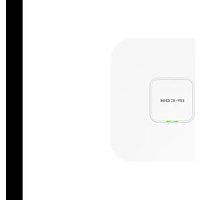


| Product Type | Wireless Access Point |
| Brand | IP-COM |
| Model | EW12 |
| Wi-Fi Standards | IEEE 802.11b/g/n |
| Frequency Band | 2.4 GHz |
| Maximum Data Rate | 300 Mbps |
| Ethernet Ports | 1 x 10/100 Mbps Fast Ethernet (PoE supported) |
| Power Supply | PoE (802.3af) or DC 12V/1A |
| Dimensions (W x D x H) | 180 mm x 120 mm x 30 mm |
| Weight | 200 g |
| Antenna Type | 2 x external omnidirectional (5 dBi) |
| Wireless Security | WEP, WPA/WPA2-PSK, WPA2-Enterprise |
| Management | Web interface, SNMP, Telnet |
| Operating Modes | Access Point, Repeater, WDS |
| Operating Temperature | 0°C to 40°C |
| Storage Temperature | -20°C to 70°C |
| Humidity | 10% to 90% (non-condensing) |
| Mounting | Wall / Ceiling mountable |
| LED Indicators | Power, LAN, WLAN |
| Certifications | CE, FCC, RoHS |
Frequently Asked Questions - EW12 IP-COM
User questions about EW12 IP-COM
0 question about this device. Answer the ones you know or ask your own.
Ask a new question about this device
Download the instructions for your Access Point in PDF format for free! Find your manual EW12 - IP-COM and take your electronic device back in hand. On this page are published all the documents necessary for the use of your device. EW12 by IP-COM.
USER MANUAL EW12 IP-COM
AC2600 Tri-band Cable-Free WiFi System(Mini Basestation)
EW12
Package contents
EW12 x 1
Bracket x 1
Screw (BA3.0 x 25 mm, head diameter: 6.0 mm) x 4
Expansion bolt (Inner diameter: 2.4 mm, length: 26.4 mm) x 4
Plastic strap x 2
Power adapter x 1
Expansion nut (Inner diameter: 2.51 mm, height: 14.5 mm) x 4
PoE injector x 1
Quick installation guide x 1
Ethernet cable x 1
Getting to know your device
LED indicator

| LED indicator | Description |
| SYS | Solid green: The system is starting up or is not working properly.Blinking green: The system works properly.Off: The device is powered off, or the LED indicators are turned off. |
| LINK | When the device works inRoutermodeSlowly blinking green: Connected to the internetBlinking red: Fails to access the internetWhen the device works inAPmodeSlowly blinking green: Connected to another node. Excellent connectionBlinking yellow: Connected to another node. Fair connectionFast blinking green: Connecting to another nodeBlinking red: Fails to connect to the router node, or the router node fails to access the internet |
Jack/Port/button

| Jack/Port/Button | Description |
| POWER | DC power jack.It is used to connect to the included power adapter to supply power to the device. |
| RESET | Reset button.When the SYS LED indicator is blinking, hold down this button for about 8 seconds, and then release it when all LED indicators light solid green. When the SYS LED indicator blinks again, the device is restored to factory settings. |
| PoE WAN/LAN1 | 10/100/1000 Mbps PoE port for power supply and data transmission.When no power sources are available at hand, use the included PoE injector instead.When the device works in Router mode, this port functions as a WAN port used to connect to a modem or an Ethernet jack.When the device works in AP mode, this port functions as a LAN port used to connect to a device under the LAN. |
| LAN2 | 10/100/1000 Mbps auto-negotiation port used to connect to a device under the LAN. |

The bracket is used to install the device onto ceilings, walls or poles. See II Install the device for details.
① Screw holes for ceiling installation
② Plastic strap holes for pole installation
③ Slots for wall installation.
I. Set up the device
Tips
EW12 supports management through the web UI, IMS cloud and App. This part instructs how to manage the device through the web UI. For more management types, please refer to relevant documents.
Please choose Scenario 1 or Scenario 2 to perform your configuration depending on your networking requirement. PoE power supply is used for illustration.
Scenario 1: Serve as a router
- Use an Ethernet cable to connect the PoE WAN/LAN1 port of EW12 to the PoE port of the PoE injector.
- Use an Ethernet cable to connect the LAN port of the PoE injector to the internet.
- Use the included power adapter to connect the PoE injector to a power source.
- Connect a computer or a WiFi-enabled device (for example: a smart phone) to EW12.
- For a computer
Use an Ethernet cable to connect the computer to the LAN2 port of EW12.
- For a smart phone
Connect the smart phone to the WiFi network of EW12. The default SSID can be found on the label at the bottom of the device.
![graph TD A["PoE port"] --> B["PoE injector"] B --> C["LAN port"] C --> D["IP-COM"] D --> E["IP-COM_XXXXXX"] D --> F["IP-COM_WAN/LAN1"] D --> G["IP-COM_WAN/LAN2"] D --> H["IP-COM"] style A fill:#f9f,stroke:#333 style B fill:#ccf,stroke:#333 style C fill:#cfc,stroke:#333 style D fill:#fcc,stroke:#333…](/content/2026/07/1524323/images/ff958689c78418bd34f76c9c8286e147c5ff566ae7a069caa97cfdf0dc80f62e.jpg)
- Start a web browser on the computer or on the smart phone, and visit 192.168.5.1 or
www.ipcwifi.com.
- Click Start, then follow the on-screen instructions to configure the internet settings.

Scenario 2: Serve as an AP
When serving as an AP, the device can be added into an existing Mesh network established by this model (EW12) of other devices in a wireless manner for network extension.
- Place the device (newly-added node) near the node serving as a router (hereafter referred to as the router node), and power on the newly-added node. When the SYS LED indicator blinks green and the LINK LED indicator blinks red, the system completes startup.
![graph TD A["PoE port"] --> B["PoE injector"] B --> C["Internet"] C --> D["IP-COM"] D --> E["IP-COM_XXXXXX"] D --> F["Setting Wi-Fi"] D --> G["Wi-Fi"] D --> H["IP-COM_XXXXXX Choose a NETWORK..."] D --> I["Or"]](/content/2026/07/1524323/images/9238905255691504e76d09f58b17656174073174f34c11b9aa009bb757ae4336.jpg)

- Refer to steps 4 and 5 in Scenario 1: Serve as a router to log in to the web UI of the existing router node.
- Click Details on the System Status page, and click the Add button corresponding to the newly-added node.
When the LINK LED indicator of the newly-added node turns from fast green blinking to slow green blinking,
the node is added into the Mesh network of the existing router node.
Tips
If the LINK LED indicator does not blink green slowly, reset the newly-added node to factory settings and try again.
![graph TD A["Internet"] -->|WAN| B["IP-COM_XXXXXX"] B --> C["User Device"] B --> D["Cable-Free Devices"] E["A new device is detected"] --> F["SN"] F --> G["Add"]](/content/2026/07/1524323/images/5f39dd7e6fed7a38e976a22397f3f28e08438a242b73c010b7a5c53bffebebc1.jpg)
-
Relocate the newly-added node, and power it on. Ensure that:
-
The wall between nodes is less than two.
- The node is within the coverage of the existing Mesh network.
When the SYS LED indicator of the newly-added node blinks green, check the status of the LINK LED indicator. Adjust the position of the newly-added node according to the descriptions in the following table until the LINK LED indicator turns to slow green blinking.
| Slow green blinking | Excellent connection |
| Yellow blinking | Fair connection. You are recommended to move the newly-added node closer to the upstream node (router node or another node in the Mesh network). |
| Red blinking | Fails to connect to the upstream node. Move the newly-added node closer to the upstream node. |
Done. Now, you can install the newly-added node to the selected position.
The SSID and password of the newly-added node are the same with the existing router node, providing you
with the better WiFi signal when you are moving around.
II. Install the device
Tips
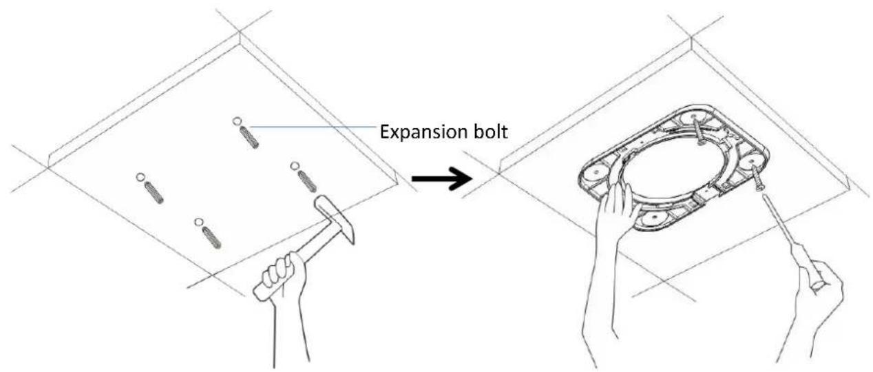
- You may need a marker, a rubber hammer, a hammer drill, a drill bit, a screwdriver, and a ladder for the installation. Please prepare them yourself.
- The device supports ceiling, wall, pole and desktop installations. Please choose the appropriate option as required. This guide uses ceiling and pole installations as an example.
Ceiling installation
1

2

Tips
Option A applies to general situations while option B is better if the ceiling material is weak, for example drywall.
③Option A
Option B

4

Pole installation
1

2

Appendix A FAQ
Q1. The device fails to access the internet when serving as a router. What should I do?
A1. Try the following solutions:
- Check whether the PoE WAN/LAN1 port of the device is connected to a modem or an Ethernet jack properly.
- Log in to the web UI of the device, choose Internet Settings, and check the connection status. If it is not Connected, follow the on-screen instructions to solve the problem.
- If the problem persists, contact your ISP to check whether your internet service is normal.
Q2: The device fails to access the internet when working in AP mode. What should I do?
A2: Try the following solutions:
- Check whether the LINK LED indicator of the device serving as a router blinks green slowly. If not, refer to Q1 to solve the problem.
- Relocate the device closer to another node with the LINK blinking green slowly LED indicator in the Mesh network.
Q3: How to reset the device to factory settings?
A3: When the SYS LED indicator is blinking, hold down the RESET button for about 8 seconds, and then release it when all LED indicators light solid on. When the SYS LED indicator blinks green again, the device is restored to factory settings.
Q4: I cannot log in to the web UI of the device. What should I do?
A4. Try the following solutions:
- Enter www.ipcwifi.com or 192.168.5.1 in the address bar (not search bar) of a web browser.
If a WiFi-enabled device, such as a smart phone, is used to configure the device, ensure that the smart phone is connected to the WiFi network of the device successfully. -
If a smart phone is used to configure the device, ensure that the mobile data is disabled.
-
If a computer is used to configure the device, ensure that the computer is connected to the LAN2 port of the device, and the Ethernet cable is connected properly.
- Reset the device to factory settings, and try again.
Appendix B Recommended WiFi coverage solutions
| Scenario | Solution (Quantity) |
| 80-user capacity | EW12 x 2 |
| 100-user capacity | EW12 x 3 |
Appendix C Specifications
| Item | Parameter |
| Frequency band | 2.4 GHz, 5.2 GHz, 5.8 GHz |
| Wireless rate | 400 Mbps + 867 Mbps + 1300 Mbps |
| Networking technology | Mesh |
| Antenna | 5 x 4 dBi omni-directional antennas |
| Jack/Port | 1 power jack, 2 x 10/100/1000 Mbps auto-negotiation RJ45 ports |
| Button | 1 RESET button |
| WAN port | 1 WAN port at most |
| Dimensions (L x H x W) | 170 mm × 170 mm × 36 mm |
| Installation type | Ceiling, pole, wall and desktop installations |
CE
CE Mark Warning
This is a Class A product. In a domestic environment, this product may cause radio interference, in which case the user may be required to take adequate measures.
The mains plug is used as disconnect device; the disconnect device shall remain readily operable.
NOTE: (1) The manufacturer is not responsible for any radio or TV interference caused by unauthorized modifications to this equipment. (2) To avoid unnecessary radiation interference, it is recommended to use a shielded RJ45 cable.
Declaration of Conformity
Hereby, SHENZHEN IP-COM Networks Co., Ltd. declares that the radio equipment type EW12 is in compliance with Directive 2014/53/EU.
The full text of the EU declaration of conformity is available at the following internet address:
http://ip-com.com.cn/en/ce.html
Operating Frequency:
2.4 GHz: EU/2412-2472MHz (CH1-CH13)
5 GHz: EU/5150-5250MHz (CH36-CH48), EU/5470-5725MHz (CH100-CH116, CH132-CH140)
EIRP Power (Max.):
2.4 GHz: 19.97dBm
5 GHz: 22.97dBm
Software Version: V15.11.0.X
Italiano
Operating Environment
● Temperature: 0° C - 40° C
● Humidity: (10% - 90%) RH, non-condensing

RECYCLING
This product bears the selective sorting symbol for Waste electrical and electronic equipment (WEEE). This means that this product must be handled pursuant to European directive 2012/19/EU in order to be recycled or dismantled to minimize its impact on the environment.
User has the choice to give his product to a competent recycling organization or to the retailer when he buys new electrical or electronic equipment.
For EU/EFTA, this product can be used in the following countries:
| BE | BG | CZ | DK | DE | EE | IE | EL | ES | FR | |
| HR | IT | CY | LV | LT | LU | HU | MT | NL | AT | |
| PL | PT | RO | SI | SK | FI | SE | UK |
FCC Statement
This equipment has been tested and found to comply with the limits for a Class A digital device, pursuant to Part 15 of the FCC Rules. These limits are designed to provide reasonable protection against harmful interference in a residential installation. This equipment generates, uses and can radiate radio frequency energy and, if not installed and used in accordance with the instructions, may cause harmful interference to radio communications. However, there is no guarantee that interference will not occur in a particular installation. If this equipment does cause harmful interference to radio or television reception, which can be determined by turning the equipment off and on, the user is encouraged to try to correct the interference by one or more of the following measures:
— Reorient or relocate the receiving antenna.
— Increase the separation between the equipment and receiver.
— Connect the equipment into an outlet on a circuit different from that to which the receiver is connected.
— Consult the dealer or an experienced radio/TV technician for help.
Operation is subject to the following two conditions: (1) this device may not cause harmful interference, and (2) this device must accept any interference received, including interference that may cause undesired operation.
Radiation Exposure Statement
This device complies with FCC radiation exposure limits set forth for an uncontrolled environment and it also complies with Part 15 of the FCC RF Rules.
This equipment should be installed and operated with minimum distance 20cm between the radiator & your body.
Caution:
Any changes or modifications not expressly approved by the party responsible for compliance could void the user's authority to operate this equipment.
This transmitter must not be co-located or operating in conjunction with any other antenna or transmitter.
Operating frequency: 2412-2462MHz, 5150-5250MHz, 5725-5850MHz
NOTE: (1) The manufacturer is not responsible for any radio or TV interference caused by unauthorized modifications to this equipment. (2) To avoid unnecessary radiation interference, it is recommended to use a shielded RJ45 cable.
Technical Support
Address: Room 101, Unit A, First Floor, Tower E3, NO.1001, Zhongshanyuan Road, Nanshan District, Shenzhen, China. 518052
Tel: (86755) 2765 3089
Email: info@ip-com.com.cn
Website: www.ip-com.com.cn
Copyright
©2020 IP-COM Networks Co., Ltd. All rights reserved.
This documentation (including pictures, images, and product specifications, etc.) is for reference only. To improve internal design, operational function, and/or reliability, IP-COM reserves the right to make changes to the products described in this document without obligation to notify any person or organization of such revisions or changes.


- PACKAGE CONTENTS
- GETTING TO KNOW YOUR DEVICE
- JACK/PORT/BUTTON
- SET UP THE DEVICE
- TIPS
- SCENARIO 1: SERVE AS A ROUTER
- SCENARIO 2: SERVE AS AN AP
- INSTALL THE DEVICE
- CEILING INSTALLATION
- ③OPTION A
- OPTION B
- POLE INSTALLATION
- APPENDIX A FAQ
- Q1. THE DEVICE FAILS TO ACCESS THE INTERNET WHEN SERVING AS A ROUTER. WHAT SHOULD I DO
- A1. TRY THE FOLLOWING SOLUTIONS
- Q2: THE DEVICE FAILS TO ACCESS THE INTERNET WHEN WORKING IN AP MODE. WHAT SHOULD I DO
- A2: TRY THE FOLLOWING SOLUTIONS
- Q3: HOW TO RESET THE DEVICE TO FACTORY SETTINGS
- Q4: I CANNOT LOG IN TO THE WEB UI OF THE DEVICE. WHAT SHOULD I DO
- A4. TRY THE FOLLOWING SOLUTIONS
- APPENDIX B RECOMMENDED WIFI COVERAGE SOLUTIONS
- CE
- CE MARK WARNING
- DECLARATION OF CONFORMITY
- ITALIANO
- OPERATING ENVIRONMENT
- FCC STATEMENT
- RADIATION EXPOSURE STATEMENT
- CAUTION
- TECHNICAL SUPPORT
- COPYRIGHT
Brand : IP-COM
Model : EW12
Category : Access Point