
SubStage SSIEXT07 - Subwoofer KICKER - Free user manual and instructions
Find the device manual for free SubStage SSIEXT07 KICKER in PDF.
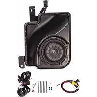


| Product Type | Subwoofer |
| Model | SubStage SSIEXT07 |
| Brand | Kicker |
| Size | 6.75 inches (170 mm) |
| RMS Power Handling | 150 Watts |
| Peak Power Handling | 300 Watts |
| Impedance | 4 ohms |
| Sensitivity | 86 dB |
| Frequency Response | 30 - 500 Hz |
| Mounting Depth | 2.625 inches (67 mm) |
| Weight | 4.5 lbs (2.0 kg) |
| Voice Coil | Single 4-ohm |
| Recommended Enclosure | Sealed or ported |
| Wiring Termination | Standard spring-loaded terminals |
| Materials | Polypropylene cone, rubber surround |
| Maintenance | Wipe with a dry cloth; keep away from moisture |
| Safety | Disconnect power before servicing; avoid short circuits |
| Spare Parts & Repairability | Contact Kicker customer support for parts |
| General Information | Designed for shallow-mount installations; compatible with most car audio systems |
Frequently Asked Questions - SubStage SSIEXT07 KICKER
User questions about SubStage SSIEXT07 KICKER
0 question about this device. Answer the ones you know or ask your own.
Ask a new question about this device
Download the instructions for your Subwoofer in PDF format for free! Find your manual SubStage SSIEXT07 - KICKER and take your electronic device back in hand. On this page are published all the documents necessary for the use of your device. SubStage SSIEXT07 by KICKER.
USER MANUAL SubStage SSIEXT07 KICKER
SSIEXT07
Designed for 2007 and newer GM ® Silverado/Sierra Extended Cab vehicles (Not compatible with vehicles equipped with the full-width rear bench)
Subwoofer Power Harness

Subwoofer Body Harness
Installation
- Disconnect the negative battery cable from the battery. (For diesel engines with dual batteries disconnect both negative cables)
- Remove cover on the driver's end of the dash. Fig. 1
- Remove the bolt securing the parking brake release lever. Some trucks may not have a release lever but there is still a bolt in that location that needs to be removed. Fig. 2
- Remove the two screws securing the panel below the steering column and pull the panel loose. Fig. 2
- Remove the two screws securing the panel below the radio and pull the panel loose.


- Pull loose the radio bezel and disconnect wiring. Fig. 3
- Remove the six screws securing the radio and HVAC controls. HVAC control wiring does not need to be disconnected. Fig. 4


-
Pull radio from dash and disconnect all wiring.
-
Route the signal input wire with the white two pin connector on it along the driver's side of the vehicle and up to the driver's kick panel or radio opening depending on installation. (If vehicle is equipped with the Factory Premium sound system, refer to the instructions for Factory Premium sound system for signal wire routing and connection.)
Subwoofer Input Connection with Optional Amplifier
- Connect the white two pin connector of the amplifier harness to the corresponding connector of the subwoofer harness.
Subwoofer Input Connection without Optional Amplifi er and without Factory Premium Audio
- Connect the six inch adaptor harness to the end of the two pin connector. Locate position 2 and 9 on the radio connector and install one of the blue wire taps onto the wire. Lay the wire in the open channel, fold the wire tap over and squeeze with a pair of pliers until it snaps shut. Connect the green wire of the adaptor harness to the wire in position 2 and the brown wire to the wire in position 9. Fig. 7
Subwoofer Input Connection with Factory Premium Audio
- Pry loose the storage tray in the center console. Fig. 5
- Starting at the end of the subwoofer harness that was routed toward the dash, carefully cut the sheathing back about 30 inches. Fig. 6


- Pull the signal wire out and route it under the carpet and into the center console. Connect the six inch adaptor harness to the end of the two pin connector. Locate the blue with a white stripe wire and the green with a black strip wire. Install one of the blue wire taps onto each wire. Lay the wire in the open channel, fold the wire tap over and squeeze with a pair of pliers until the wire tap snaps shut. Fig. 7
- Connect the green wire of the adaptor harness to the blue/white wire and the brown wire of the adaptor harness to the green/black wire. Fig. 8


NOTE: Remember to place your warranty card in the glove box for future use.
Power Wire Routing
NOTE: If you are installing the optional amplifier system, install the power wire for it at this time.
- Snap loose the driver's side front and rear threshold panel along the bottom of the door opening.
- Snap loose the driver's side kick panel by pulling straight back.
- Remove the plastic cover over the power distribution center on the passenger's side of the firewall near the battery.
- Connect the subwoofer power wire to the accessory lug. Make sure the ring terminal is oriented so that the wire will exit the bottom of the plastic cover once it is reinstalled. Torque to 9 +/- 1.5 Nm. Fig. 9
- If the accessory lug is not available, pull back the rubber battery lug cover on the passenger's side battery and attach the power wire ring terminal to the lug on the battery terminal indicated in Fig. 10


- Route the power wire along the fi rewall to the factory grommet on the driver's side, secure with wire ties.
- Using a razor knife make a cross shaped incision in the large rubber grommet and feed the power wire from the engine compartment to the cabin. Fig. 11
- Install the connector on the end of the power harness inside the cabin. The black connector should have a block out plug installed in one side to prevent the power wire from being inserted into the wrong position in the connector.
- Connect the black two pin connector on the power wire to the corresponding connector on the subwoofer harness.


NOTE: If you are installing the optional amplifier system, it does not matter in what order the three wires are on the 3-pin connector, but the terminals can only be inserted one way. If the terminal will not go into the connector, simply turn it 180 degrees and try again. Push the terminals in until they click and lock into place.
-
Connect the black ground wire to the bolt directly above the hood release lever. Torque to 9Nm, +/- 1.5Nm. Fig. 12
-
Continue running the subwoofer harness down the drivers side of the vehicle to the back of the cab and then over to the passenger's side under the carpet. The end of the wire needs to come out from under the rear passenger's seat approximately in the center and on top of the carpet in front of the seat belt receptacles.
NOTE: If installing the optional amplifier system, refer to the amplifier instruction manual to complete the installation.
Subwoofer Mounting
- Remove the most forward rear passenger's side seat nut located by the door opening.
- Remove the bolt securing the rear seat buckle assembly and remove temporarily. Fig. 13
- Connect the subwoofer wiring to the subwoofer harness and place the enclosure over the seat stud and the seat buckle stud. Make sure the subwoofer harness is set on the driver's side of the rear seat buckle assembly. Fig. 14
- Replace the rear seat buckle assembly over the top of the subwoofer bracket and reinstall the factory bolt. Tighten bolt to 53 Nm (39 ft/lb)
- Replace the rear seat nut and tighten to 109 Nm (80 ft/lb)


- Install fuse into fuse holder.
- Reinstall all previously removed parts in reverse order.
- Reconnect negative battery cable. Torque to 17Nm.
Troubleshooting the Kicker Integrated Systems
If you experience a problem once the Subwoofer is installed use this guide to locate the trouble.
The radio is working, but the Subwoofer is not working:
- Check the battery voltage to make sure it is not discharged below 11 volts.
- Check the negative battery cable to see if it has been securely tightened back on the battery.
- Check the inline fuse located near the battery to make sure it is plugged in completely, and not blown.
- Check the inline +12Volt power-connector near the firewall to make sure it is plugged in securely.
- Check the inline connectors near the subwoofer enclosure to make sure they are plugged securely.
- Check the ground wire connection to make sure it is tightly secured to the proper ground in the vehicle.
- Check the audio input signal connection to make sure it is secure and connected to the proper wiring.
- Test with different music in case there is no low frequency audio in the initial sound check.
There is a buzz or rattle noise that accompanies the low frequency element of the music:
- Check for a connector or any other object that could be very near the enclosure.
- Check the subwoofer enclosure mounting brackets to make sure they are secure.
| Symptom Possible Cause Solution | ||
| No Subwoofer Output | Fuse not installed in inline fuse holder on subwoofer and / or amp harness | Install fuse into fuse holder. Refer to instructions for correct placement |
| Low battery voltage Recharge the battery | ||
| Negative battery cable not connected | Reconnect negative battery cable | |
| Power wire connector not connected to body harness | Connect power wire to body harness. Check for loose connection | |
| Ground wire not grounded properly | Check ground wire with voltmeter to insure it is a good ground | |
| Balance or fader controls not set to neutral position | Set balance and fader control to center settings. (only effects stand alone subwoofer kit) | |
| No low frequency information in music | Test with several different songs | |
| Subwoofer harness not properly / completely connected to sub-woofer. | Securely fasten both of the connectors on the subwoofer harness to the subwoofer. Check for loose connections. | |
| Radio Not Coming On | Blown radio fuse Refer to owner's manual for radio fuse location and value | |
| Low battery voltage Recharge the battery | ||
| Radio Comes On, But No Sound From Any Speakers | Fuse not installed in inline fuse holder on amplifi er harness | Install fuse into fuse holder. Refer to instructions for correct place-ment |
| Ground wire not grounded properly | Check ground wire with voltmeter to insure it is a good ground | |
| Low battery voltage Recharge the battery | ||
If you continue to experience problems after troubleshooting, please contact KICKER Technical Support at (800) 256-0808 ext. 6009, or support@kicker.com.

stillwaterdesigns
P.O. Box 459 • Stillwater, Oklahoma 74076 • USA • (405) 624–8510
Limited Warranty

sound stages™ by KICKER.
Audio System Upgrade
Please retain this card and your receipt with vehicle Contains valuable information should you need service
SSIEXT07

When purchased from an Authorized KICKER Dealer, KICKER warrants this product to be free from defects in material and workmanship under normal use for a period of ONE (1) YEAR from date of original purchase, or TWO (2) YEARS if installed by a KICKER dealer. If this product is identified as "Refurbished" or "B Goods", the warranty is limited to a period of THREE (3) MONTHS from date of original purchase. In all cases you must have the original receipt. Should service be necessary under this warranty for any reason due to manufacturing defect or malfunction during the warranty period, KICKER will repair or replace (at its discretion) the defective merchandise with equivalent merchandise. Warranty replacements may have cosmetic scratches and blemishes. Discontinued products may be replaced with more current equivalent products. This warranty is valid only for the original purchaser and is not extended to owners of the product subsequent to the original purchaser. Any applicable implied warranties are limited in duration to a period of the express warranty as provided herein beginning with the date of the original purchase at retail, and no warranties, whether express or implied, shall apply to this product thereafter. Some states do not allow limitations on implied warranties; therefore, these exclusions may not apply to you. This warranty gives you specific legal rights; however you may have other rights that vary from state to state.
WHAT TO DO IF YOU NEED WARRANTY OR SERVICE:
Defective merchandise should be returned to your local Authorized Stillwater Designs (KICKER) Dealer for warranty service. Assistance in locating an Authorized Dealer can be found at www.kicker.com or by contacting Stillwater Designs directly. You can confirm that a dealer is authorized by asking to see a current authorized dealer window decal. If it becomes necessary for you to return defective merchandise directly to Stillwater Designs (KICKER), call the KICKER Customer Service Department at (405) 624-8510 for a Return Merchandise Authorization (RMA) number. Package only the defective items in a package that will prevent shipping damage, and return to:
Stillwater Designs, 3100 North Husband St, Stillwater, OK 74075
The RMA number must be clearly marked on the outside of the package. Please return only defective components. The return of functioning items increases your return freight charges. Non-defective items will be returned freight collect to you. Include a copy of the original receipt with the purchase date clearly visible, and a "proof-of-purchase" statement listing the Customer's name, Dealer's name and invoice number, and product purchased. Warranty expiration on items without proof-of-purchase will be determined from the type of sale and manufacturing date code. Freight must be prepaid; items sent freight-collect, or COD, will be refused.
WHAT IS NOT COVERED?
This warranty is valid only if the product is used for the purpose for which it was designed. It does not cover:
• Damage due to improper installation
- Subsequent damage to other components
• Damage caused by exposure to moisture, excessive heat, chemical cleaners, and/or UV radiation
• Damage through negligence, misuse, accident or abuse. Repeated returns for the same damage may be considered abuse
• Any cost or expense related to the removal or reinstallation of product
- Speakers damaged due to amplifier clipping or distortion
- Items previously repaired or modified by any unauthorized repair facility
- Return shipping on non-defective items
- Products with tampered or missing barcode labels
- Products returned without a Return Merchandise Authorization (RMA) number
- Freight Damage
• The cost of shipping product to KICKER
• Service performed by anyone other than KICKER
HOW LONG WILL IT TAKE?
KICKER strives to maintain a goal of 1 week service for all acoustics (subwoofers, midrange drivers, tweeters, crossovers, etc) returns. Delays may be incurred if lack of replacement inventory or parts is encountered. Failure to follow these steps may void your warranty. Any questions can be directed to the KICKER Customer Service Department at (405) 624-8510. Contact your International KICKER dealer or distributor concerning specific procedures for your country's warranty policies. Note: All specifications and performance figures are subject to change. Please visit www.kicker.com for the most current information.
P.O. Box 459 • Stillwater, Oklahoma 74076 • USA • (405) 624-8510
SD stillwaterdesigns
STAKIKERAI KICKERAI KICKERAI KICKERAI KICKERAI KICKERAI KICKERAI KICKERAI KICKERAI KICKERAI KICKERAI KICKERAI KICKERAI KICKERAI KICKERAI KICKERAI KICKERAI KICKERAI KICKERAI KICKERAI KICKERAI KICKERAI KICKERAI KICKERAI KICKERAI KICKERAI KIC




- SSIEXT
- INSTALLATION
- SUBWOOFER INPUT CONNECTION WITH OPTIONAL AMPLIFIER
- SUBWOOFER INPUT CONNECTION WITHOUT OPTIONAL AMPLIFI ER AND WITHOUT FACTORY PREMIUM AUDIO
- SUBWOOFER INPUT CONNECTION WITH FACTORY PREMIUM AUDIO
- POWER WIRE ROUTING
- SUBWOOFER MOUNTING
- TROUBLESHOOTING THE KICKER INTEGRATED SYSTEMS
- THE RADIO IS WORKING, BUT THE SUBWOOFER IS NOT WORKING
- THERE IS A BUZZ OR RATTLE NOISE THAT ACCOMPANIES THE LOW FREQUENCY ELEMENT OF THE MUSIC
- STILLWATERDESIGNS
- LIMITED WARRANTY
- SOUND STAGES™ BY KICKER
- AUDIO SYSTEM UPGRADE
- WHAT TO DO IF YOU NEED WARRANTY OR SERVICE
- STILLWATER DESIGNS, 3100 NORTH HUSBAND ST, STILLWATER, OK
- WHAT IS NOT COVERED
- HOW LONG WILL IT TAKE
- SD STILLWATERDESIGNS
Brand : KICKER
Model : SubStage SSIEXT07
Category : Subwoofer