
XV-Z21000 - Projector SHARP - Free user manual and instructions
Find the device manual for free XV-Z21000 SHARP in PDF.


| Product Type | DLP Projector |
| Brand | Sharp |
| Model | XV-Z21000 |
| Display Technology | Single-chip DLP |
| Native Resolution | 1280 x 720 (HD Ready) |
| Brightness | 2000 ANSI Lumens |
| Contrast Ratio | 3000:1 |
| Lamp Type | 200W SHP |
| Lamp Life (Normal/Eco) | 2000 / 3000 hours |
| Throw Ratio | 1.5 - 1.8:1 |
| Zoom | Manual, 1.2x |
| Keystone Correction | Vertical ±15° |
| Inputs | HDMI, Component, Composite, S-Video, VGA, RS-232C |
| Outputs | Trigger 12V, Audio Out |
| Dimensions (W x H x D) | 315 x 97 x 280 mm |
| Weight | 4.5 kg |
| Power Consumption | 300 W (Standby < 1 W) |
| Noise Level (Normal/Eco) | 33 / 28 dB |
| Remote Control | IR Remote with batteries |
| Warranty | 1 year (lamp 90 days) |
| Cleaning Instructions | Use a soft dry cloth; clean filter every 100 hours |
| Safety Features | Auto power-off, overheat protection, Kensington lock |
| Spare Parts & Repairability | Replacement lamp module available; user-replaceable filters |
Frequently Asked Questions - XV-Z21000 SHARP
User questions about XV-Z21000 SHARP
0 question about this device. Answer the ones you know or ask your own.
Ask a new question about this device
Download the instructions for your Projector in PDF format for free! Find your manual XV-Z21000 - SHARP and take your electronic device back in hand. On this page are published all the documents necessary for the use of your device. XV-Z21000 by SHARP.
USER MANUAL XV-Z21000 SHARP

HDMI™
HIGH-DEFINITION MULTIMEDIA INTERFACE

SPECIAL NOTE FOR USERS IN THE U.K.
The mains lead of this product is fitted with a non-rewireable (moulded) plug incorporating a 10A fuse. Should the fuse need to be replaced, a BSI or ASTA approved BS 1362 fuse marked or and of the same rating as above, which is also indicated on the pin face of the plug, must be used.
Always refi t the fuse cover after replacing the fuse. Never use the plug without the fuse cover fi tted. In the unlikely event of the socket outlet in your home not being compatible with the plug supplied, cut off the mains plug and fi t an appropriate type.
DANGER:
The fuse from the cut-off plug should be removed and the cut-off plug destroyed immediately and disposed of in a safe manner.
Under no circumstances should the cut-off plug be inserted elsewhere into a 13A socket outlet, as a serious electric shock may occur.
To fit an appropriate plug to the mains lead, follow the instructions below:
WARNING:
THIS APPARATUS MUST BE EARTHED.
IMPORTANT:
The wires in this mains lead are coloured in accordance with the following code:
Green-and-yellow : Earth
Blue : Neutral
Brown : Live
As the colours of the wires in the mains lead of this apparatus may not correspond with the coloured markings identifying the terminals in your plug proceed as follows:
- The wire which is coloured green-and-yellow must be connected to the terminal in the plug which is marked by the letter E or by the safety earth symbol 1/2 or coloured green or green-and-yellow.
- The wire which is coloured blue must be connected to the terminal which is marked with the letter N or coloured black.
- The wire which is coloured brown must be connected to the terminal which is marked with the letter L or coloured red.
IF YOU HAVE ANY DOUBT, CONSULT A QUALIFIED ELECTRICIAN.
Introduction
IMPORTANT
- For your assistance in reporting the loss or theft of your Projector, please record the Serial Number located on the bottom of the projector and retain this information.
- Before recycling the packaging, please ensure that you have checked the con tents of the carton thoroughly against the list of "Supplied accessories" on page 4.
Model No.: XV-Z21000
Serial No.:
WARNING:

High brightness light source. Do not stare into the beam of light, or view directly. Be especially careful that children do not stare directly into the beam of light.
WARNING:
To reduce the risk of fire or electric shock, do not expose this product to rain or moisture.
See bottom of projector.

CAUTION
RISK OF ELECTRIC SHOCK. DO NOT REMOVE SCREWS EXCEPT SPECIFIED USER SERVICE SCREW.

CAUTION: TO REDUCE THE RISK OF ELECTRIC SHOCK, DO NOT REMOVE COVER. NO USER-SERVICEABLE PARTS EXCEPT LAMP UNIT. REFER SERVICING TO QUALIFIED SERVICE PERSONNEL.

The lightning fl ash with arrowhead sym bol within an equilateral triangle, is in tended to alert the user to the presence of uninsulated "dangerous voltage" within the product's enclosure that may be of suffi cient magnitude to constitute a risk or electric shock to persons.

The exclamation point within a triangle is intended to alert the user to the presence of important operating and maintenance (servicing) instructions in the literature accompanying the product.
WARNING:
The cooling fan in this projector continues to run for about 90 seconds after the projector enters standby mode. During normal operation, when putting the projector into standby mode always use the STANDBY button on the projector or the STANDBY button on the remote control. Ensure the cooling fan has stopped before disconnecting the power cord.
DURING NORMAL OPERATION, NEVER TURN THE PROJECTOR OFF BY DISCONNECTING THE POWER CORD. FAILURE TO OBSERVE THIS WILL RESULT IN PREMATURE LAMP FAILURE.
WARNING:
This is a Class A product. In a domestic environment this product may cause radio interference in which case the user may be required to take adequate measures.
PRODUCT DISPOSAL
This projector utilizes tin-lead solder, and a pressurized lamp containing a small amount of mercury. Disposal of these materials may be regulated due to environmental considerations. For disposal or recycling information, please contact your local authorities or, if you are located in the United States of America, the Electronic Industries Alliance: www.eiae.org.
Caution Concerning Lamp Replacement
See "Regarding the Lamp" on page 48.
This SHARP projector uses a DLP ® chip. This very sophisticated panel contains 2,073,600 pixels (micromirrors). As with any high technology electronic equipment such as large screen TVs, video systems and video cameras, there are certain acceptable tolerances that the equipment must conform to.
This unit has some inactive pixels within acceptable tolerances which may result in inactive dots on the picture screen. This will not affect the picture quality or the life expectancy of the unit.
- The DLP logo, the DLP medallion and BrilliantColor TM are trade marks of Texas Instruments.
- Microsoft ® and Windows ® are registered trade marks of Microsoft Corporation in the United States and/or other countries.
• PC/AT is a registered trademark of International Business Machines Corporation in the United States. - Macintosh is a registered trademark of Apple Computer, Inc. in the United States and/or other countries.
- HDMI, the HDMI logo and High-Definition Multimedia Interface are trademarks or registered trademarks of HDMI Licensing LLC.
- All other company or product names are trademarks or registered trademarks of their respective companies.
- Some IC chips in this product include confidential and/or trade secret property belonging to Texas Instruments. Therefore you may not copy, modify, adapt, translate, distribute, reverse engineer, reverse assemble or discompile the contents thereof.
Preparing
Introduction
Contents....3
Accessories 4
IMPORTANT SAFEGUARDS....5
Part Names and Functions ....8
Using the Remote Control ....11
Inserting the Batteries.... 11
Usable Range 11
Quick Start
Quick Start 12
Setup
Setting Up the Projector ....14
Setting Up the Projector 14
Standard Setup (Front Projection) 14
Projection (PRJ) Mode 15
Ceiling-mount Setup 15
Picture (Screen) Size and Projection Distance ..... 16
Connections
Samples of Cables for Connection .....17
Connecting to Video Equipment ....18
Connecting to a Computer ....23
Controlling the Projector by a Computer ....24
Using
Basic Operation
Turning the Projector On/Off 25
Connecting the Power Cord 25
Turning the Projector On 25
Turning the Power Off
(Putting the Projector into Standby Mode) ..... 26
Image Projection 27
Switching the Input Mode....27
Adjusting the Projected Image 27
Operating with the Remote Control .....29
Switching the Iris Setting 29
Adjusting the Contrast 29
Adjusting the Quantity of Light 29
Freezing a Moving Image.... 29
Selecting the Picture Mode 29
Selecting the Screen Size ....30
Resize Mode 30
Useful Features
Menu Bar Items ....32
Using the Menu Screen 34
Menu Selections (Adjustments) 34
Picture Adjustment ("Picture" Menu) .....36
Selecting the Picture Mode 36
Adjusting the Image 36
Selecting the Gamma Position 37
Switching the Iris Setting 37
Lamp Setting 37
Using the Advanced 37
Adjusting the Colors 37
Adjusting the BrilliantColor™ 38
Selecting the Progressive Mode 38
Selecting the Film Mode 38
Reducing Image Noise (DNR) 38
Mosquito Noise Reduction (MNR) 38
Adjusting the Unveil Control 39
Adjusting the Automatic Contrast 39
Resetting All Adjustment Items 39
Gamma Adjustment ("Gamma" Menu) .....40
Selecting the Gamma Position 40
Adjusting the Gamma 40
Computer Image Adjustment ("Fine Sync" Menu) .....41
Adjusting the Computer Image 41
Special Modes Setting 41
Checking the Input Signal.... 41
Auto Sync (Auto Sync Adjustment) 41
Using the "Options" Menu ....42
Adjusting the Image Position 42
Adjusting the Vertical Size of the Display (Subtitle Setting).....42
Adjusting the Overscan 42
Adjusting the White Level/Black Level 43
Turning LED Off 43
Checking the Lamp Life Status.... 43
Setting On-screen Display 43
Setting the Video System 43
Signal Type Setting 44
Adjusting the Color Space 44
Adjusting the Dynamic Range 44
Selecting the Background Image 44
Adjusting the Economy Mode 44
Selecting the Transmission Speed (RS-232C) ..... 45
Fan Mode Setting 45
Reversing/Inverting Projected Images 45
Returning to the Default Settings 45
Other Function 45
Selecting the On-screen Display Language ..... 45
Reference
Appendix
Maintenance Indicators/Maintenance .....46
Regarding the Lamp 48
Lamp 48
Caution Concerning the Lamp.... 48
Replacing the Lamp 48
Removing and Installing the Lamp Unit 49
Resetting the Lamp Timer 50
Connecting Pin Assignments ....51
RS-232C Specifications and Command
Settings....52
Wired Remote Control Terminal
Specifications....59
Computer Compatibility Chart ....60
Troubleshooting....61
Specifi cations 63
Dimensions 64
Index 65
Supplied accessories

Remote control
RRMCGA500WJSB

Two AA size batteries

Lens cap (attached)
PCAPH1056CESA

Terminal cover
GCOVAB677WJKB

21 pin RCA conversion adaptor QSOCZ0361CEZZ

Video cable
QCNWGA001WJZZ
For Europe, except U.K.

DVI to D-sub cable (6' (1.8 m))
QCNWGA010WJPZ
Operation manual
Power cord*
(1)

For Europe, except U.K.
(6' (1.8 m))
QACCVA011WJPZ
(2) (3)

For U.K. and Singapore (6' (1.8 m))
QACCBA036WJPZ

For Australia, New Zealand and Oceania (6' (1.8 m))
QACCLA018WJPZ
* Use the power cord that corresponds to the wall outlet in your country.
Optional accessories
■ Lamp unit AN-K20LP
■ 3 RCA to 15-pin D-sub cable (9'10" (3.0 m)) AN-C3CP2
■ DVI to 15-pin D-sub adaptor (7.9" (20 cm)) AN-A1DV
■ DVI cable (9'10" (3.0 m)) AN-C3DV

Note
- Some of the optional accessories may not be available depending on the region. Please check with your nearest Sharp Authorized Service Center or Dealer.
Marks Used in This Operation Manual

Info
...... Indicates safeguards when using the projector.

Note
...... Indicates additional information for setting up and operating the projector.
- In this operation manual, the illustration and the screen display are simplified for explanation, and may differ slightly from actual display.
For Future Reference
IndexMaintenance Troubles

P. 46 and 47

nd 62

P. 65
CAUTION: Please read all of these instructions before you operate this product and save these instructions for later use.
Electrical energy can perform many useful functions. This product has been engineered and manufactured to assure your personal safety. BUT IMPROPER USE CAN RESULT IN POTENTIAL ELECTRICAL SHOCK OR FIRE HAZARDS. In order not to defeat the safeguards incorporated in this product, observe the following basic rules for its installation, use and servicing.
1. Read Instructions
All the safety and operating instructions should be read before the product is operated.
2. Retain Instructions
The safety and operating instructions should be retained for future reference.
3. Heed Warnings
All warnings on the product and in the operating instructions should be adhered to.
4. Follow Instructions
All operating and use instructions should be followed.
5. Cleaning
Unplug this product from the wall outlet before cleaning. Do not use liquid cleaners or aerosol cleaners. Use a damp cloth for cleaning.
6. Attachments
Do not use attachments not recommended by the product manufacturer as they may cause hazards.
7. Water and Moisture
Do not use this product near water-for example, near a bath tub, wash bowl, kitchen sink, or laundry tub; in a wet basement; or near a swimming pool; and the like.
8. Accessories
Do not place this product on an unstable cart, stand, tripod, bracket, or table. The product may fall, causing serious injury to a child or adult, and serious damage to the product. Use only with a cart, stand, tripod, bracket, or table recommended by the manufacturer, or sold with the product. Any mounting of the product should follow the manufacturer's instructions, and should use a mounting accessory recommended by the manufacturer.
9. Transportation
A product and cart combination should be moved with care. Quick stops, excessive force, and uneven surfaces may cause the product and cart combination to overturn.

10. Ventilation
Slots and openings in the cabinet are provided for ventilation to ensure reliable operation of the product and to protect it from overheating, and these openings must not be blocked or covered. The open ings should never be blocked by placing the product on a bed, sofa, rug, or other similar surface. This prod uct should not be placed in a built-in installation such as a book case or rack unless proper ventilation is provided or the manufacturer's in struc tions have been adhered to.
11. Power Sources
This product should be operated only from the type of power source indicated on the marking label. If you are not sure of the type of power supply to your home, consult your product dealer or local power company. For products intended to operate from battery power, or other sources, refer to the operating instructions.
12. Grounding or Polarization
This product is provided with one of the following types of plugs. If the plug should fail to fit into the power outlet, please contact your electrician.
Do not defeat the safety purpose of the plug.
a. Two-wire type (mains) plug.
b. Three-wire grounding type (mains) plug with a grounding terminal.
This plug will only fit into a grounding type power outlet.
13. Power-Cord Protection
Power-supply cords should be routed so that they are not likely to be walked on or pinched by items placed upon or against them, paying particular attention to cords at plugs, convenience receptacles, and the point where they exit from the product.
14. Lightning
For added protection for this product during a lightning storm, or when it is left unattended and unused for long periods of time, unplug it from the wall outlet and disconnect the cable system. This will pre vent damage to the product due to lightning and power-line surges.
15. Overloading
Do not overload wall outlets, extension cords, or integral convenience receptacles as this can result in a risk of fire or electric shock.
16. Object and Liquid Entry
Never push objects of any kind into this product through openings as they may touch dangerous voltage points or short-out parts that could result in a fire or electric shock. Never spill liquid of any kind on the product.
17. Servicing
Do not attempt to service this product yourself as opening or removing covers may expose you to dangerous voltage or other hazards. Refer all servicing to qualified service personnel.
18. Damage Requiring Service
Unplug this product from the wall outlet and refer servicing to qualified service personnel under the following conditions:
a. When the power-supply cord or plug is damaged.
b. If liquid has been spilled, or objects have fallen into the product.
c. If the product has been exposed to rain or water.
d. If the product does not operate normally by following the operating instructions. Adjust only those controls that are covered by the operating instructions, as an improper adjustment of other controls may result in damage and will often require extensive work by a qualified technician to restore the product to normal operation.
e. If the product has been dropped or damaged in any way.
f. When the product exhibits a distinct change in performance, this indicates a need for service.
19. Replacement Parts
When replacement parts are required, ensure the service technician has used replace ment parts specified by the manufacturer or have the same characteristics as the original part. Unauthorized substitutions may result in fire, electric shock, or other hazards.
20. Safety Check
Upon completion of any service or repairs to this product, ask the service technician to perform safety checks to determine that the product is in proper operating condition.
21. Wall or Ceiling Mounting
This product should be mounted to a wall or ceiling only as recommended by the manu facturer.
22. Heat
This product should be situated away from heat sources such as radiators, heat registers, stoves, or other products (including amplifiers) that produce heat.
Observe the following safeguards when setting up your projector.
Caution concerning the lamp unit
■ Potential hazard of glass particles if lamp ruptures. In case of lamp rupture, contact your nearest Sharp Authorized Service Center or Dealer for replacement. See “Regarding the Lamp” on page 48.
Caution concerning the setup of the projector
For minimal servicing and to maintain high image quality, SHARP recommends that this projector be installed in an area free from humidity, dust and cigarette smoke. When the projector is subjected to these environments, the vents and lens must be cleaned more often. As long as the projector is regularly cleaned, use in these environments will not reduce the overall operation life of the unit. Internal cleaning should only be performed by a Sharp Authorized Service Center or Dealer.
Do not set up the projector in places exposed to direct sunlight or bright light.
■ Position the screen so that it is not in direct sunlight or room light. Light falling directly on the screen washes out the colors, making viewing diffi cult. Close the curtains and dim the lights when setting up the screen in a sunny or bright room.
Caution regarding placing of the projector
■ Place the projector on a level site within the adjustment range ( ±5 degrees) of the adjustment foot.

■ After the projector is purchased, a faint smell from the vent may appear when the power is first turned on. This is normal and is not a malfunction. It will disappear after the projector is used for a while.
When using the projector in high-altitude areas such as mountains (at altitudes of approximately 4,900 feet (1,500 meters) or more)
- When you use the projector in high-altitude areas with thin air, set “Fan Mode” to “High”. Neglecting this can affect the longevity of the optical system.
Warning about placing the projector in a high position
■ When placing the projector in a high position, ensure that it is secured carefully to avoid personal injury caused by the projector falling down.
Do not subject the projector to hard impact and/or vibration.
■ Protect the lens so as not to hit or damage the surface of the lens.
Rest your eyes occasionally.
■ Continuously watching the screen for long hours will cause eye strain. Be sure to occasionally rest your eyes.
Avoid locations with extremes of temperature.
■ The operating temperature of the projector is from 41° F to 95° F (+ 5° C to + 35° C).
■ The storage temperature of the projector is from -4°F to 140°F ( -20°C to +60°C ).
Do not block the exhaust and intake vents.
- Allow at least 1113/16 inches (30 cm) of space between the exhaust vent and the nearest wall or obstruction.
■ Be sure that the intake vent and the exhaust vent are not obstructed.
If the cooling fan becomes obstructed, a protection circuit will automatically put the projector into standby mode to prevent overheat damage. This does not indicate a malfunction. (See page 46.) Remove the projector power cord from the wall outlet and wait at least 10 minutes. Place the projector where the intake and exhaust vents are not blocked, plug the power cord back in and turn on the projector. This will return the projector to the normal operating condition. - When turning off the projector, the cooling fan runs to decrease the internal temperature for a while. Unplug the power cord after the cooling fan stops. The period the cooling fan runs will vary, depending on the circumstances and the internal temperature.
Caution regarding usage of the projector
When using the projector, be sure not to subject it to hard impact and/or vibration, as this can result in damage. Take extra care with the lens. Before moving the projector, be sure to unplug the power cord from the wall outlet, and disconnect any other cables connected to it.
■ Do not carry the projector by holding the lens.
■ When storing the projector, re-attach the lens cap. (See page 8.)
- Do not expose the projector to direct sunlight or place next to heat sources. Doing so may affect the cabinet color or cause deformation of the plastic cover.
Other connected equipment
■ When connecting a computer or other audio-visual equipment to the projector, make the connections AFTER unplugging the power cord of the projector from the AC outlet and turning off the equipment.
■ Please read the operation manuals of the projector and the equipment to be connected for instructions on how to make the connections.
Using the projector in other countries
The power supply voltage and the shape of the plug may vary depending on the region or country you are using the projector in. When using the projector overseas, be sure to use an appropriate power cord for the country you are in.
Temperature monitor function

TEMP.
If the projector starts to overheat due to setup problems or blockage of the air vents, “X” and “TEMP.”
illuminate in the lower left corner of the picture. If the temperature continues to rise, the lamp will turn off, the temperature warning indicator on the projector will blink, and after a 90-second cooling-off period the projector will enter standby mode. Refer to “Maintenance Indicators/Maintenance” on page 46 for details.

Info
- The cooling fan regulates the internal temperature, and its performance is automatically controlled. The sound of the fan may change during projector operation due to changes in the fan speed. This does not indicate malfunction.
- Do not unplug the power cord during projection or cooling fan operation. This can cause damage due to rise in internal temperature, as the cooling fan also stops.
Part Names and Functions
Numbers in order to the main pages in this operation manual where the topic is explained.
Projector

Using the Terminal Cover
When the projector is used on a desktop, high mounted or ceiling mounted, attach the terminal cover (supplied) to hide the connecting cables.
Attaching the Terminal Cover
① Align the hook on the terminal cover with the insert hole in the hook at the back of the projector.
② Press the hook in the direction indicated with the ar row to fasten the ter mi nal cover to the projector.
③ Insert the terminal cover into the mounting groove on the projector while pushing the tabs inside the terminal cover to the out side with your fingers.

Remove the rubber cap attached on the projec tor and at tach the hooks.
Projector (Rear View)

| Terminal Description Page | ||
| 1 | COMPONENT/RGB1, 2 terminalsConnecting video equipment with component output terminal (DVD player, etc.) or a computer with analog RGB output terminal. | 20, 21 |
| 2 | S-VIDEO terminalConnecting video equipment with S-video output terminal (DVD player, VCR, etc.). | 22 |
| 3 | VIDEO terminalConnecting video equipment without S-video output terminal. | 22 |
| 4 | DVI terminalConnecting video equipment with DVI output terminal (DVD player, DTV decoder, computer, etc.). | 18-20, 23 |
| 5 | HDMI1, 2 terminalsConnecting video equipment with HDMI output terminal. | 18 |
| 6 | RS-232C terminalConnecting a computer to control the projector. | 24 |
| 7 | TRIGGER terminalWhen the projector is turned on, a control signal (DC 12V) outputs from this terminal. If an electric screen or other compatible device is connected, it can be turned on when the projector is turned on. | — |
| 8 | WIRED REMOTE control input terminalConnecting the remote control via a cable when the projector is placed out of the reach of remote control signals. | 10 |
Using the Kensington Lock
- This projector has a Kensington Security Standard connector for use with a Kensington MicroSaver Security System. Refer to the information that came with the system for instructions on how to use it to secure the projector.
Numbers in order to the main pages in this operation manual where the topic is explained.
Remote Control

Connecting the Remote Control to the Projector
When the remote control cannot be used due to the range or positioning of the projector, connect a 3.5 mm minijack cable (commercially available) from the WIRED R/C JACK on the top of the remote control to the WIRED REMOTE control input terminal on the rear of the projector.

Using the Remote Control
Inserting the Batteries
1 Pull down the tab on the cover and remove the cover towards the direction of the arrow.
2 Insert the supplied batteries and put back the cover.
- Make sure the polarities correctly match the + and marks inside the battery compartment.
- When putting back the cover, be sure that the cover clicks in place and settles.


Usable Range
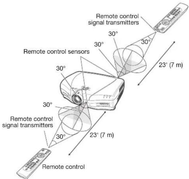
The remote control can be used to control the projector within the ranges shown in the illustration.

Note
- The signal from the remote control can be reflected off a screen for easy operation. However, the effective distance of the signal may differ depending on the screen material.
When using the remote control:
- Be sure not to drop, expose to moisture or high temperature.
- The remote control may malfunction under a fluorescent lamp. In this case, move the projector away from the fluorescent lamp.
Incorrect use of the batteries may cause them to leak or explode. Please follow the precautions below.

Caution
- Danger of explosion if bettery is incorrectly replaced.
Replace only with the same or equivalent type. - Insert the batteries making sure the polarities correctly match the ④ and ⑤ marks inside the battery compartment.
- Batteries of different types have different properties, therefore do not mix batteries of different types.
- Do not mix new and old batteries.
This may shorten the life of new batteries or may cause old batteries to leak. - Remove the batteries from the remote control once they have run out, as leaving them in can cause them to leak. Battery fluid from leaked batteries is harmful to skin, therefore be sure to first wipe them and then remove them using a cloth.
- The batteries included with this projector may run down in a short period, depending on how they are kept. Be sure to replace them as soon as possible with new batteries.
- Remove the batteries from the remote control if you are not to use the remote control for a long time.
- Comply with the rules (ordinance) of each local government when disposing of worn-out batteries.
Quick Start
This section provides an example showing how to connect the projector to video equipment with a brief explanation of the steps from connection through to image projection.
For details, see the pages suggested in each step.

1. Place the projector facing a screen
→ Page 14

2. Connect the projector to the video equipment and plug the power cord into the AC socket of the projector
→ Pages 18-25

To VIDEO terminal
Connect the audio output terminal of the video equipment to the audio input terminal of the audio equipment using an audio cable.
3. Remove the lens cap and turn the projector on
→ Page 25

Pointing the remote control towards the projector, press the ⏻ON button.

4. Turn the video equipment on and start playback

5. Select the input mode
→ Page 27
Press the VIDEO button on the remote control to select "VIDEO" for the Input mode.

- Press 📄/ 📅/ 📋 or the remote control to switch the Input mode.
6. Adjust the projector angle, focus and zoom
→ Pages 27, 28
- The focus is adjusted by rotating the focus ring.

- Zooming is adjusted by moving the zoom knob.

- The projector angle is adjusted by using the adjustment feet. As for adjustment of the vertical position of the projected image, use the lens shift dial.

7. Turn the power off
→ Page 26
Press ⓍSTANDBY on the remote control, then press that button again while the confirmation message is displayed, to put the projector into standby mode.

STANDBY
▼ On-screen display
Enter STANDBY mode? Yes: Press Again No: Please Wait
Shutting Down. Please Wait.
- Unplug the power cord from the AC outlet after the cooling fan stops.
Setting Up the Projector
Setting Up the Projector
For optimal image quality, position the projector perpendicular to the screen with the projector's feet flat and level.

Note
- The projector lens should be centered in the middle of the screen. If the horizontal line passing through the lens center is not perpendicular to the screen, the image will be distorted, making viewing difficult.
- For optimal image, position the screen so that it is not in direct sunlight or room light. Light falling directly on the screen washes out the colors, making viewing diffi cult. Close the curtains and dim the lights when setting up the screen in a sunny or bright room.
- A polarizing screen cannot be used with this projector.
Standard Setup (Front Projection)
■ Place the projector at the required distance from the screen according to the desired picture size.
Example of standard setup

L : Projection distance
H1 : Distance from the lens center to the bottom of the image (when the lens is shifted to the lowest position)
H2 : Distance from the lens center to the bottom of the image (when the lens is shifted to the highest position)

Note
- For details, refer to "Picture (Screen) Size and Projection Distance" on page 16.
Projection (PRJ) Mode
The projector can use any of the 4 projection modes, shown in the diagram below. Select the mode most appropriate for the projection setting in use. (You can set the PRJ Mode in "Options" menu. See page 45.)
■ Table mounted, front projection

■ Ceiling mounted, front projection
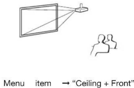
■ Table mounted, rear projection (with a translucent screen)

■ Ceiling mounted, rear projection (with a translucent screen)

Ceiling-mount Setup
It is recommended that you use the optional Sharp ceiling-mount bracket for this installation. Before mounting the projector, contact your nearest Sharp Authorized Service Center or Dealer to obtain the recommended ceiling-mount bracket (sold separately).
- AN-NV6T ceiling-mount bracket, its AN-TK201 and AN-TK202 extension tubes.
Invert the image by setting "Ceiling + Front" in "PRJ Mode". See page 45 for use of this function.
Indication of the Projection Image Size and Projection Distance
For details, refer to "Picture (Screen) Size and Projection Distance" on page 16.
Example : When using a wide screen (16:9)

Picture (Screen) Size and Projection Distance
The projection screen size varies according to the distance from the lens of the projector to the screen. Install the projector so that projected images are projected onto the screen at the optimum size by referring to the table below. Use the values in the table as a reference when installing the projector.
When using a wide screen (16:9): In case of displaying the 16:9 picture on the whole of the 16:9 screen.

| Picture (Screen) size Projection distance | L | Distance from the lens center to the bottom of the image [H] | ||||
| Diag. (x) Width Height Maximum [L1] Minimum [L2] Lower [H1] Upper [H2] | ||||||
| 300" | 261.5" (6.6 m) | 147.1" (3.7 m) | 54'10" (16.7 m) | 40'9" (12.4 m) | -147" (-374 cm) | 0" (0 cm) |
| 250" | 217.9" (5.5 m) | 122.6" (3.1 m) | 45'8" (13.9 m) | 33'11" (10.3 m) | -122" (-311 cm) | 0" (0 cm) |
| 200" | 174.3" (4.4 m) | 98.1" (2.5 m) | 36'6" (11.1 m) | 27'1" (8.3 m) | -98" (-249 cm) | 0" (0 cm) |
| 150" | 130.7" (3.3 m) | 73.5" (1.9 m) | 27'4" (8.3 m) | 20'3" (6.2 m) | -73" (-187 cm) | 0" (0 cm) |
| 120" | 104.6" (2.7 m) | 58.8" (1.5 m) | 21'10" (6.7 m) | 16'2" (4.9 m) | -58" (-149 cm) | 0" (0 cm) |
| 110" | 95.9" (2.4 m) | 53.9" (1.4 m) | 20'0" (6.1 m) | 14'10" (4.5 m) | -53" (-137 cm) | 0" (0 cm) |
| 100" | 87.2" (2.2 m) | 49" (1.2 m) | 18'2" (5.5 m) | 13'5" (4.1 m) | -49" (-125 cm) | 0" (0 cm) |
| 80" | 69.7" (1.8 m) | 39.2" (1.0 m) | 14'6" (4.4 m) | 10'9" (3.3 m) | -39" (-100 cm) | 0" (0 cm) |
| 60" | 52.3" (1.3 m) | 29.4" (0.7 m) | 10'10" (3.3 m) | 8'0" (2.4 m) | -29" (-75 cm) | 0" (0 cm) |
| 40" | 34.9" (0.9 m) | 19.6" (0.5 m) | 7'2" (2.2 m) | 5'3" (1.6 m) | -19" (-50 cm) | 0" (0 cm) |
x : Picture size (diag.) (inches)
L1: Maximum Projection distance (ft/m)
L2 : Minimum Projection distance (ft/m)
The formula for picture size and projection distance
L1 = (0.05593x - 0.05550)/0.3048 (ft) H1 = -1.2453x/2.54 (in)
L2 = (0.04158x - 0.05665)/0.3048 (ft) H2 = 0
When using a normal screen (4:3) and projecting 4:3 image (SIDE BAR Mode)

| Picture (Screen) size Projection distance [L] | Distance from the lens center to the bottom of the image [H] | |||||
| Diag. (x) Width Height Maximum [L1] Minimum [L2] Lower [H1] Upper [H2] | ||||||
| 250" | 200" (5.1 m) | 150" (3.8 m) | 56'0" (17.1 m) | 41'7" (12.7 m) | -150" (-381 cm) | 0" (0 cm) |
| 200" | 160" (4.1 m) | 120" (3.0 m) | 44'9" (13.6 m) | 33'2" (10.1 m) | -120" (-305 cm) | 0" (0 cm) |
| 150" | 120" (3.0 m) | 90" (2.3 m) | 33'6" (10.2 m) | 24'10" (7.6 m) | -90" (-229 cm) | 0" (0 cm) |
| 120" | 96" (2.4 m) | 72" (1.8 m) | 26'9" (8.2 m) | 19'10" (6.1 m) | -72" (-183 cm) | 0" (0 cm) |
| 110" | 88" (2.2 m) | 66" (1.7 m) | 24'6" (7.5 m) | 18'2" (5.5 m) | -66" (-168 cm) | 0" (0 cm) |
| 100" | 80" (2.0 m) | 60" (1.5 m) | 22'3" (6.8 m) | 16'6" (5.0 m) | -60" (-152 cm) | 0" (0 cm) |
| 80" | 64" (1.6 m) | 48" (1.2 m) | 17'9" (5.4 m) | 13'2" (4.0 m) | -48" (-122 cm) | 0" (0 cm) |
| 60" | 48" (1.2 m) | 36" (0.9 m) | 13'4" (4.1 m) | 9'10" (3.0 m) | -36" (-91 cm) | 0" (0 cm) |
x : Picture size (diag.) (inches)
L1 : Maximum Projection distance (ft/m)
L2 : Minimum Projection distance (ft/m)
The formula for picture size and projection distance
L1 = (0.06845x - 0.05550)/0.3048 (ft) H1 = -1.524x/2.54 (in)
L2 = (0.05089x - 0.05665)/0.3048 (ft) H2 = 0
When using a normal screen (4:3): In case of setting the 16:9 picture to the full horizontal width of the 4:3 screen.

| Picture (Screen) size Projection distance [L] | Distance from the lens center to the bottom of the image [H] | |||||
| Diag. (x) Width Height Maximum [L1] Minimum [L2] Lower [H1] Upper [H2] | ||||||
| 250" | 200" (5.1 m) | 150" (3.8 m) | 41'11" (12.8 m) | 31'1" (9.5 m) | -112" (-286 cm) | 0" (0 cm) |
| 200" | 160" (4.1 m) | 120" (3.0 m) | 33'6" (10.2 m) | 24'10" (7.6 m) | -90" (-229 cm) | 0" (0 cm) |
| 150" | 120" (3.0 m) | 90" (2.3 m) | 25'1" (7.6 m) | 18'7" (5.7 m) | -67" (-171 cm) | 0" (0 cm) |
| 120" | 96" (2.4 m) | 72" (1.8 m) | 20'0" (6.1 m) | 14'10" (4.5 m) | -54" (-137cm) | 0" (0 cm) |
| 110" | 88" (2.2 m) | 66" (1.7 m) | 18'4" (5.6 m) | 13'7" (4.1 m) | -49" (-126 cm) | 0" (0 cm) |
| 100" | 80" (2.0 m) | 60" (1.5 m) | 16'8" (5.1 m) | 12'4" (3.8 m) | -45" (-114 cm) | 0" (0 cm) |
| 80" | 64" (1.6 m) | 48" (1.2 m) | 13'3" (4.1 m) | 9'10" (3.0 m) | -36" (-91 cm) | 0" (0 cm) |
| 60" | 48" (1.2 m) | 36" (0.9 m) | 9'11" (3.0 m) | 7'4" (2.2 m) | -27" (-69 cm) | 0" (0 cm) |
x : Pictre size (diag.) (inches)
L1 : Maximum Projection distance (ft/m)
L2 : Minimum Projection distance (ft/m)
The formula for picture size and projection distance
L1 = (0.05133x - 0.05550)/0.3048 (ft) H1 = -1.143x/2.54 (in)
L2 = (0.03817x - 0.05665)/0.3048 (ft) H2 = 0

Note
- Allow a margin of error in the value in the diagrams above.
- When the distance from the lens center to the bottom of the image (H) is a negative number, this indicates that the bottom of the image is below the lens center.
Samples of Cables for Connection
- For more details of connection and cables, refer to the operation manual of the connecting equipment.
- You may need other cables or connectors not listed below.
| Equipment Input | signal Cable | Terminal on the projector | |
Audio-visual equipment   Camera/video game Camera/video game  | HDMI video H | DMI cable (commercially available) HDMI1, 2 |  |
| Component video | Component cable (commercially available) COMPONENT/ZAZD | NT/RGB1, 2 | |
3 RCA to 15-pin D-sub cable (sold separately: AN-C3CP2)DVI to 15-pin D-sub adaptor (sold separately: AN-A1DV) 3 RCA to 15-pin D-sub cable DVI to 15-pin D-sub adaptor 3 RCA to 15-pin D-sub cable DVI to 15-pin D-sub adaptor | DVI | ||
| Terminal for using the dedicated cable | Dedicated cable attached to the connected equipment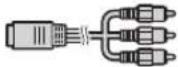 | COMPONENT/RGB1, 2COMPONENT1 | |
| RGB video 5 | RCA RGB cable (commercially available) COMPONENT/ | RGB1, 2COMPONENT1 | |
S-video S-video cable (commercially available) S-VIDEO | S-VIDEO | ||
| Terminal for using the dedicated cable | Dedicated cable attached to the connected equipment | ||
| Video Video | o cable (commercially available) VIDEO | VIDEO | |
| Terminal for using the dedicated cable | Dedicated cable attached to the connected equipment | ||
Computer RGB video | DVI to D-sub cable (supplied accessory) | DVI | |
| DVI cable (sold separately: AN-C3DV) | |||
Connecting to Video Equipment
Before connecting, be sure to unplug the power cord of the projector from the AC outlet and turn off the devices to be connected. After making all connections, turn on the projector and then the other devices.
Connecting Equipment with HDMI Output Terminal to the HDMI Terminal on the Projector
HDMI is a new specialized interface capable of delivering a video and audio signal to the terminal using just one cable. Since this projector does not support an audio signal by itself, use an amplifier or other audio device.
For video connection, use a cable that conforms to HDMI standards. Using cables that do not conform to HDMI standards may result in a malfunction.


Note
- HDMI (High-Definition Multimedia Interface) is a digital AV interface that can deliver a high-definition video signal, multi-channel audio signal, and bi-directional control signal all in just one cable.
- Because it is compatible with the HDCP (High-bandwidth Digital Content Protection) system, the digital video signal does not degrade when transmitted, and a high-quality image with a simple connection can be enjoyed.
Connecting Equipment with the HDMI Output Terminal to the DVI Terminal on the Projector


Note
- When connecting the projector to the video equipment in this way, select "Signal Type" in the "Options" menu. See page 44.
- When a DVI to HDMI conversion cable is connected to the HDMI terminal, a proper picture may not be displayable.
Connecting Video Equipment with the DVI Output Terminal to the DVI Terminal on the Projector


Note
- When connecting the projector to the video equipment in this way, select "Signal Type" in the "Options" menu. See page 44.
Connecting Component Video Equipment to the DVI Terminal on the Projector


Note
- When connecting the projector to the video equipment in this way, select "Signal Type" in the "Options" menu. See page 44.
Connecting to Video Equipment (Continued)
Connecting RGB Equipment to the DVI Terminal on the Projector


Note
- When connecting the projector to the video equipment in this way, select "A. RGB" for "Signal Type" in the "Options" menu. See page 44.
Connecting RGB Equipment to the COMPONENT/RGB Terminals on the Projector


Note
- The (HD/C sync) and (VD) terminals may be used depending on the specifications of the RGB equipment connected to this projector. Please refer to the operation manual of the RGB equipment for details.
Connecting Component Video Equipment to the COMPONENT/RGB Terminals on the Projector

Connecting to Video Equipment (Continued)
Connecting to Equipment with S-video Output Terminal

Connecting to Equipment with Video Output Terminal

Connecting to a Computer
Ensure that the computer is the last device to be turned on after all the connections are made.
Connecting to a Computer Using a DVI Cable


Note
- When connecting the projector to the video equipment in this way, select "Signal Type" in the "Options" menu. See page 44.
Connecting to a Computer Using the DVI to D-sub Cable


Note
- When connecting the projector to the video equipment in this way, select "Signal Type" in the "Options" menu. See page 44.
- Refer to “Computer Compatibility Chart” on page 60 for a list of computer signals compatible with the projector. Use with computer signals other than those listed may cause some of the functions not to work.
- A Macintosh adaptor may be required for use with some Macintosh computers. Contact your nearest Sharp Authorized Service Center or Dealer.
- Depending on the computer you are using, an image may not be projected unless the computer's external output port is switched on. (e.g. Press "Fn" and "F5" keys simultaneously when using a SHARP notebook computer). Refer to the specific instructions in your computer's operation manual to enable your computer's external output port.
Controlling the Projector by a Computer
When the RS-232C terminal on the projector is connected to a computer, the computer can be used to control the projector and check the status of the projector.
When connecting to a computer using an RS-232C serial control cable


Note
- The RS-232C function may not operate if your computer terminal is not correctly set up. Refer to the operation manual of the computer for details.
- For details on RS-232C specifications and commands, see page 52.

Info
- Do not connect the RS-232C cable to a port other than the RS-232C terminal on the computer. This may damage your computer or projector.
- Do not connect or disconnect an RS-232C serial control cable to or from the computer while it is on. This may damage your computer.
Turning the Projector On/Off
Connecting the Power Cord
Plug the supplied power cord into the AC socket on the rear of the projector.
- The power indicator illuminates red, and the projector enters standby mode.
Turning the Projector On
Before performing the steps in this section, connect any equipment that you use with the projector. (See pages 18-25.)
Remove the lens cap and press ON on the projector or ON on the remote control.
• The power indicator illuminates blue.

Note
- About the Lamp Indicator
The lamp indicator illuminates to indicate the status of the lamp.
Blue: The lamp is ready.
Blinking in blue: The lamp is warming up.
Red: The lamp is shut down abnormally or the lamp should be replaced.
- When switching on the projector, a slight f1 ickering of the image may be experienced within the first minute after the lamp has been illuminated. This is normal operation as the lamp's control circuitry is stabilizing the lamp output characteristics. This does not indicate malfunction.
- If the projector is put into standby mode and immediately turned on again, the lamp may take some time to illuminate.
Supplied accessory

Power cord


Info
- English is the factory preset language. If you want to change the on-screen display to another language, change the language according to the procedure on page 45.

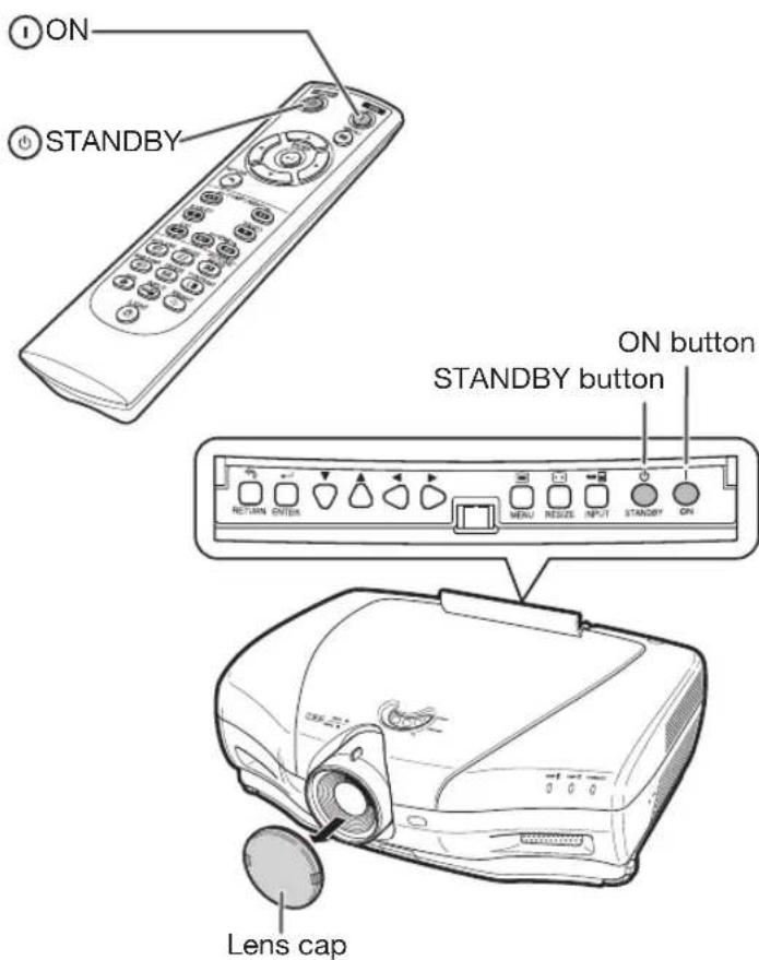
Turning the Power Off (Putting the Projector into Standby Mode)
1 Press ⏻STANDBY on the projector or ⏻STANDBY on the remote control, then press that button again while the confirmation message is displayed, to put the projector into standby mode.
2 Unplug the power cord from the AC outlet after the cooling fan stops.
- The power indicator on the projector blinks in blue while cooling.
- The power indicator changes to red when the projector finishes cooling.
▼On-screen display

Enter STANDBY mode?
Yes: Press Again No: Please Wait

Shutting Down. Please Wait.

Info
- Do not unplug the power cord during projection or cooling fan operation. This can cause damage due to the rise in internal temperature, as the cooling fan also stops.
- When connected to equipment such as an amplifier, be sure to turn off the power to the equipment connected first and then to the projector.
Image Projection
Switching the Input Mode
Select the appropriate input mode for the connected equipment.
Press Input Mode Select buttons or ⏻ INPUT on the remote control to select the input mode.
- When INPUT on the remote control or
☐ INPUT on the projector is pressed, the Input list appears. While the Input list is displayed, follow the procedure below to switch the Input mode.
① Press ⏻ INPUT or ▼/▲ to select the desired input mode.
②Press ENTER. - If ⏻ ENTER is not pressed, the projector switches to the selected input mode in a few seconds.

Note
- When no signal is received, "NO SIGNAL" will be displayed. When a signal that the projector is not preset to receive is received, "NOT REG." will be displayed.
Adjusting the Projected Image
1. Adjusting the Focus
You can adjust the focus with the focus ring on the projector.
Rotate the focus ring to adjust the focus while watching the projected image.
2. Adjusting the Image Size
You can adjust the image size using the zoom knob on the projector.
Move the zoom knob to enlarge or shrink the image size.

Input mode menu


3. Adjusting the Projector Angle Using the Adjustment Feet
The inclination of the projector can be adjusted using the adjustment feet when the projector is placed on an uneven surface or when the screen is slanted.
1
Lift the projector to adjust its height while pressing the foot releases.
2
Remove your hands from the foot releases after the height has been adjusted.
- The angle of projection is adjustable up to 5 degrees from the surface on which the projector is placed.
3
Rotate the adjustment feet to make fi ne adjustment.
- Rotate the adjustment feet to gradually raise or lower the projector. Ensure that the projector is stable and does not wobble.

Note
- When the height of the projector is adjusted, the image may become distorted, depending on the relative positions of the projector and the screen.

Info
- Do not apply too much pressure on the projector when the adjustment feet are stuck out.
- When lowering the projector, be careful not to get your fingers caught in the area between the adjustment foot and the projector.
- Hold the projector firmly while lifting or carrying.
- Do not hold by the lens area.
4. Adjusting the Vertical Position of the Image
You can move the projected image vertically by turning the lens shift dial.

Info
- Do not turn the lens shift dial beyond the upper limit and lower limit positions. This may cause the projector to malfunction.


Operating with the Remote Control
Switching the Iris Setting
This function controls the quantity of the projected light and the contrast of the image.
Press IRIS.
• Each time the button is pressed while the display is on, the mode changes in the following order:


Note
- For details, see page 37.
Adjusting the Contrast
1 Press ☐CONTRAST.
2 Press ◀ or ▶ to adjust the contrast.
3 Press ⏻ ENTER.

Note
- For details, see page 36.
Adjusting the Quantity of Light
1 Press ⒿBRIGHT.
2 Press ◀ or ▶ to adjust the quantity of light.
3 Press ⏻ ENTER.

Note
• For details, see page 36.
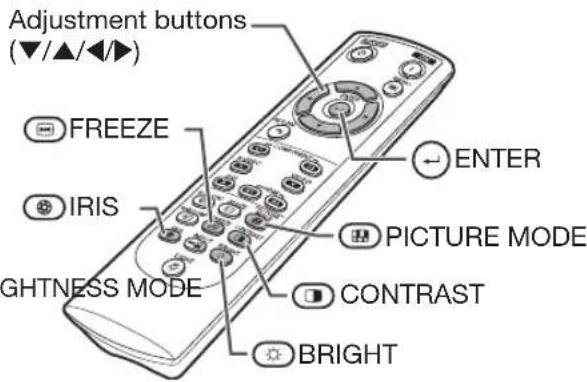
Freezing a Moving Image
1 Press FREEZE.
• The projected image is frozen.
2 Press FREEZE again to return to the moving image from the currently connected device.
Selecting the Picture Mode
You can select the appropriate picture mode to best match the projected image you are watching.
Press 📄PICTURE MODE.
• Each time the button is pressed while the display is on, the mode changes in the following order:
![graph TD A["STANDARD"] --> B["MEMORY"] C["NATURAL"] --> D["MOVIE2"] E["DYNAMIC"] --> F["MOVIE1"]](/content/2026/07/1520630/images/282847518bd4515ebc15161ddb9f06992c9e023480c0b510b3cfe606a1b63563.jpg)

- For details, see page 36.
Selecting the Screen Size
Resize Mode
This function allows you to modify or customize the resize mode to enhance the input image.
Press ☑RESIZE on the projector or ☑RESIZE on the remote control.

Note
- The RESIZE function that can be selected varies depending on the input signal (resolution and vertical frequency).
- To return to the standard image, press RETURN while "RESIZE" is displayed.


Resize Mode
| RESIZE | Output screen image |
| STRETCH | An image compressed from a 16:9 aspect ratio to a 4:3 aspect ratio is restored to a 16:9 aspect ratio and displayed at full-screen.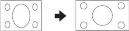 |
| NORMAL (Computer) | The image is displayed with the original aspect ratio. |
| SIDE BAR (Video) | An image with a 4:3 aspect ratio is displayed without any changes. |
| SMART STRETCH | An image with a 4:3 aspect ratio is widened to fit the entire screen.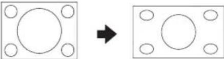 |
| CINEMA ZOOM | A CinemaScope image or an image with a 16:9 aspect ratio is displayed at full-screen |
| ZOOM 14:9 | An image with a 14:9 aspect ratio and letterboxing is enlarged while maintaining the original aspect ratio. |
| SMART ZOOM | An image with a 4:3 aspect ratio is slightly enlarged. |
| DOT BY DOT | The image is displayed according to the original input signal. |
About Copyrights
- When using the RESIZE function to select an image size with a different aspect ratio to a TV program or video image, the image will look different from its original appearance. Keep this in mind while choosing an image size.
- The use of the RESIZE, Subtitle, or Overscan function to compress or stretch the image for commercial purposes/public displays in a café, hotel, etc. may be an infringement of copyright protected by law for copyright holders. Please use caution.
- While watching non-widescreen images (4:3), if you use the RESIZE function to fill the screen or use the Overscan function to change the aspect ratio of a fixed-ratio input signal, parts of the outer edge of the image will be cut off or distorted. To watch original images as the producers intended, set “RESIZE” to “SIDE BAR” and Overscan to its default setting.
The following shows the items that can be set in the projector.
The selectable items vary depending on the selected input, input signals, or adjustment values. Items that cannot be selected will be grayed out.
![graph TD A["Main menu Sub menu"] --> B["Picture"] A --> C["Picture Mode"] A --> D["Standard"] A --> E["Gamma"] A --> F["Main menu Sub menu"] F --> G["Gamma"] F --> H["All Colors"] F --> I["Black Detail"] F --> J["Reset"] B --> B1["Page 36"] B --> B2["Page 36"] B --> B3["Contrast"] B --> B4["Bright"]…](/content/2026/07/1520630/images/c3924847e6a03d2b32c12e0e667412aa3b4dc4cf815a392b104256c72c6e7c80.jpg)
![graph TD A["Main menu Sub menu"] --> B["Fine Sync"] B --> C["1"] C --> D["Clock ←+150-150"] C --> E["Phase ←+60-60"] C --> F["H-Pos ←+150-150"] C --> G["V-Pos ←+60-60"] C --> H["Reset"] C --> I["Special Modes"] C --> J["Signal Info"] J --> K["Resolution<br>Hor Freq<br>Vert Freq"] J --> L["Auto Sync"…](/content/2026/07/1520630/images/fe81313fd63e5657dc50ff9c4d5c61ae4f04238919791cf0ec64bba1d45b8692.jpg)
![graph TD A["Main menu Sub menu"] --> B["Options"] B --> C["Image Shift"] C --> D["Subtitle"] D --> E["Page 42"] E --> F["Overscan"] F --> G["Page 42"] G --> H["Reset"] H --> I["Page 42"] I --> J["White Level"] J --> K["Black Level"] K --> L["Page 43"] L --> M["LAMP Timer(Life)"] M --> N["Page 43"] N…](/content/2026/07/1520630/images/8c5e45ad68aff33dec1207589be67beb00410424710a16d45abee14fd2423db4.jpg)
*1: The "Fine Sync" menu is not available for S-VIDEO or VIDEO Input.
*2: Can be set for HDMI Input.
*3: Can be set for DVI Input.
Using the Menu Screen


Menu Selections (Adjustments)
- This operation can also be performed by using the buttons on the projector. (Example: Adjusting "Bright")
1
Press ⓄMENU.
- The "Picture" menu screen for the selected input mode is displayed.
2
Press ▶ or ◀ to select the menu screen to adjust on the menu bar.

Note
- The "Fine Sync" menu is not available for selecting S-VIDEO or VIDEO.
Example: "Picture" menu screen when COMPONENT is selected for input mode
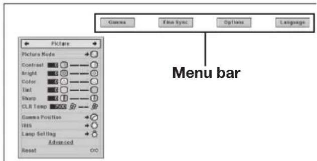
3
Press ▲ or ▼ to select the item you want to adjust.
(Example: Selecting "Bright")
To adjust the projected image while viewing it
Press ⏻ ENTER.
- The selected adjustment item (e.g. "Bright") will be displayed at the bottom of the screen.
- When ▲ or ▼ is pressed, the next item will be displayed. (e.g. “Bright” is replaced with “Color” by pressing ▼.)

Note
- Press ⓊRETURN to return to the previous screen.
4
Press ▶ or ◀ to adjust the item selected.
• The adjustment is stored.
- For some menu items, press ▶ to display its submenu and press ▲ or ▼ to select an adjustment item, and then press ⏻ENTER.
5
Press ⓄMENU.
• The menu screen will disappear.


Picture Adjustment ("Picture" Menu)

Menu operation ⇒ Page 34
①Selecting the Picture Mode
This function allows you to select the picture mode that best suits the room brightness and the type of image being projected.
| Selectable items | Description | The main default settings of each item when selecting Picture Mode | |||
| CLR Temp Br | lliantColorTM IRIS | Lamp Setting | |||
| Standard For | standard image 7500 Off High Brightness Bright | ||||
| Natural A balanced color image is obtained. 7500 Off High Brightness Bright | |||||
| Dynamic A vivid image is obtained. 7500 On High Brightness Bright | |||||
| Movie1 For viewing images with the brightness slightly toned down in a darkened room | 6500 Off Medium Mode Eco + Quiet | ||||
| Movie2 For viewing images with the brightness slightly boosted in a darkened room | 6500 Off High Contrast Eco + Quiet | ||||
| Memory | Allows you to store your picture adjustment settings. The settings stored effect each input mode. | 7500 Off High Brightness Bright | |||
- You can set or adjust each item in the "Picture" menu to your preference. Any changes you make are retained in memory.

Note
- You can also press Ⓗ PICTURE MODE on the remote control to select the picture mode. (See page 29.)
- The default settings are subject to change without notice.
②Adjusting the Image
| Adjustment items | ◀ button | ▶ button |
| Contrast | For less contrast. | For more contrast. |
| Bright | For less brightness. | For more brightness. |
| Color | For less color intensity. | For more color intensity. |
| Tint | For making skin tones purplish. | For making skin tones greenish. |
| Sharp | For less sharpness. | For more sharpness. |
| CLR Temp | For making images slightly more reddish (slightly warmer colors). | For making images slightly more bluish (slightly cooler colors). |

Note
- To reset all adjustment items, select "Yes" in "Reset" and press ⏻ ENTER. The Picture Mode settings of the selected input return to the default settings.
- As for "Contrast" and "Bright", you can make adjustments directly by using Ⓐ CONTRAST and ⚙ BRIGHT, respectively, on the remote control. (See page 29.)

Selecting the Gamma Position
This function allows you to select the desired gamma position.
See page 40 for details.

Note
- Gamma can be adjusted in greater detail with "Gamma" on the menu screen.

Switching the Iris Setting
This function controls the quantity of the projected light and the contrast of the image.
| Selectable items | Description |
| High Brightness | High brightness is given priority over high contrast. |
| Medium Mode Intermediate | mediate mode between high contrast and high brightness. |
| High Contrast | High contrast is given priority over high brightness. |

Note
- You can also use THIS on the remote control to change the Iris. (See page 29.)

Lamp Setting
| Select-able items | Bright-ness | Fan sound | Power consumption (When using AC 100V) | Lamp Life |
| Bright 100% Normal | 320W Approx. | 2,000 hours | ||
| Eco + Quiet | Approx. 80% | Low 265W Approx. | 3,000 hours | |

Note
- When “Lamp Setting” is set to “Eco+Quiet”, the power consumption will decrease and the lamp life will extend. (Projection brightness decreases approximately 20%.)

Using the Advanced
"Advanced" allows you to make even fi ner adjustments to the image so that it appears just the way you want it to.
To display the Advanced menu, select "Advanced" and press ENTER.

Note
- When the “Advanced” settings are displayed, select “Advanced” again and press ⏻ ENTER to return to the “Picture” menu.

Adjusting the Colors
Select "C.M.S." (Color Management System) in the "Advanced" menu and then press ⏻ ENTER.
This function adjusts each of the six main colors that comprise the color wheel, altering their “Hue”, “Saturation”, or “Value”.
| Selectable items Description | |
| C.M.S.-Hue | Sets the hue of the main colors. |
| C.M.S.-Saturation | Sets the Saturation of the main colors |
| C.M.S.-Value | Sets the Value of the main colors. |
| Reset | The adjustments of “Hue”, “Saturation” and “Value” of all colors are reset to the default setting. |
Adjusting "Hue", "Saturation", or "Value".
① Press ▲ or ▼ to select either “Hue”, “Saturation”, or “Value” and then press ⏻ ENTER.
② Select the color to be adjusted with ▲ or ▼ and adjust it with ◀ or ▶.
- When you press ENTER, the adjustment bar for the selected system color will be displayed at the bottom of the screen. Use this bar to make adjustments while viewing the effects on-screen.
Example of adjusting the "Hue"
| Main colors | ◀ button | ▶ button |
| Red | Closer to magenta | Closer to yellow |
| Yellow | Closer to red | Closer to green |
| Green | Closer to yellow | Closer to cyan |
| Cyan | Closer to green | Closer to blue |
| Blue | Closer to cyan | Closer to magenta |
| Magenta | Closer to blue | Closer to red |
- When “Saturation” is selected, the selected color becomes lighter (◀) or thicker (▶).
- When "Value" is selected, the selected color becomes darker (◀) or brighter (▶).
- To reset the adjustment values of each color to the default settings, select "Yes" in "Reset" and press ENTER.
⑧ Adjusting the BrilliantColor™
BrilliantColor™ uses Texas Instruments' BrilliantColor™ technology. The image becomes brighter while the color reproduction is kept at a high level.
| Selectable items Description | |
| On The BrilliantColor activated. | TM function is |
| Off The BrilliantColor activated. | TM function is not |
⑨ Selecting the Progressive Mode
For selecting the progressive display of a video signal.
| Selectable items Description |
| 3D Fast Useful to display fast-moving images such as sports and action films. |
| 3D Slow Useful to display relatively slow-moving images such as drama and documentary more clearly. |
| 2D+ This mode is ideal for games, etc. |

Note
- When using progressive inputs, "Progressive" cannot be selected.
⑩ Selecting the Film Mode
This function provides high-quality playback of images originally projected at 24 fps, such as movies on DVDs.
| Selectable items Description |
| Auto Films are detected automatically. |
| Off Films are not detected. |

Note
- When using progressive inputs, "Film Mode" cannot be selected.
⑪ Reducing Image Noise (DNR)
Video digital noise reduction (DNR) provides high quality images with minimal dot crawl and cross color noise.
| Selectable items Description | |
| Off The DNR function is not activated. | |
| Level 1 | Sets the DNR level for viewing a clearer picture. |
| Level 2 | |
| Level 3 | |

Note
Set "DNR" to "Off" in the following cases:
- When the image is blurry.
- When the contours and colors of moving images drag.
- When TV broadcasts with weak signals are projected.
⑫Mosquito Noise Reduction (MNR)
The so-called Mosquito Noise (flickering) can be reduced.
| Selectable items Description | |
| Off MNR does not function. | |
| Level 1 | Sets the MNR level for viewing a clearer picture. |
| Level 2 | |
| Level 3 | |

Adjusting the Unveil Control
This function uses edge enhancement to give the impression of added depth to images.
| Selectable items Description | |
| Off The Unveil Control function is not activated. | |
| Level 1 | Sets the Unveil Control level for viewing an image with the impression of added depth. |
| Level 2 | |
| Level 3 | |

Adjusting the Automatic Contrast
This function automatically adjusts the image contrast to suit the scene.
| Selectable items | Description |
| Off The Automatic | Contrast function is not activated. |
| Level 1 | Sets the Automatic Contrast level.Level |
| Level 3 |

Resetting All Adjustment Items
This function allows you to reset all adjustment items to the default setting.
| Selectable items Description |
| No Does not do resetting. |
| Yes Resets all adjustment items. |
Gamma Adjustment ("Gamma" Menu)
Menu operation ⇒ Page 34

① Selecting the Gamma Position
You can select the desired gamma position according to the image being projected.
| Selectable item Description |
| Standard Sharp default setting |
| Natural Gives a sold and understated image quality |
| Dynamic For viewing images in relatively bright surroundings |
| Movie1 For viewing images with the brightness slightly toned down in a darkened room |
| Movie2 For viewing images with the brightness slightly boosted in a darkened room |
| Custom Uses special software that allows the gamma curve to be adjusted. For more information on the special software, visit the Sharp website at: http://sharp-world.com/projector/. |

Note
- The gamma position you set in this menu can be selected in the “Gamma Position” in the “Picture” menu.
② Adjusting the Gamma
Adjust the gamma curve to suit your preferences.
Gamma
| Selectable item | ◀ button ▶ button | |
| All Colors You can make sync adjustment for the Red, Green and Blue mentioned below. | ||
| Red | For giving greater depth to brighter portion of image | For giving greater depth to darker portion of image in red color. |
| Green | For giving greater depth to brighter portion of image in green color. | For giving greater depth to darker portion of image in green color. |
| Blue | For giving greater depth to brighter portion of image in blue color. | For giving greater depth to darker portion of image in blue color. |
■ White Detail
| Selectable item | ◀ button | ▶ button |
| All Colors You can make sync adjustment for the Red, Green and Blue mentioned below. | ||
| Red For less contrast in red color | For more contrast in red color | |
| Green For less contrast in green color | For more contrast in green color | |
| Blue For less contrast in blue color | For more contrast in blue color | |
Black Detail
| Selectable item | ◀ button | ▶ button |
| All Colors You can make sync adjustment for the Red, Green and Blue mentioned below. | ||
| Red For less brightness in red color | For more brightness in red color | |
| Green For less brightness in green color | For more brightness in green color | |
| Blue For less brightness in blue color | For more brightness in blue color | |
- When you select an adjustment item and press ENTER, the adjustment bar for the selected adjustment item will be displayed at the bottom of the screen. Use this bar to make adjustments while viewing the effects on-screen.
Note
- To reset all adjustment items, select "Yes" in "Reset" and press ⏻ ENTER.
Computer Image Adjustment ("Fine Sync" Menu)
The illustration shown here is for explanation and may be different from the actual on-screen display.

① Adjusting the Computer Image
Use the Fine Sync function in case of irregularities such as vertical stripes or flickering in portions of the screen.
| Selectable item Description | |
| Clock Adjusts vertical noise. | |
| Phase Adjusts horizontal noise (similar to tracking on your VCR). | |
| H-Pos Centers the | on-screen image by moving it to the left or right. |
| V-Pos Centers the | on-screen image by moving it up or down. |

Note
- You can automatically adjust the computer image by setting "Auto Sync" in the "Fine Sync" menu to "Normal" or "High speed", or pressing Ⓔ AUTO SYNC on the remote control.
- Depending on the type of input signal, the adjustment range for each setting may vary or the adjustment may not be available at all.
- To reset all adjustment items, select "Yes" in "Reset" and press ⏻ ENTER.
② Special Modes Setting
Ordinarily, the type of input signal is detected and the correct resolution mode is automatically selected. However, for some signals, the optimal resolution mode in "Special Modes" in the "Fine Sync" menu may need to be selected to match the computer display mode.

Note
- Avoid displaying computer patterns which repeat every other line (horizontal stripes). (Flickering may occur, making the image hard to see.)
• Information on the currently selected input signal can be confirmed in item ③.
Menu operation ⇒ Page 34
③ Checking the Input Signal
This function allows you to check the current input signal information.
④ Auto Sync (Auto Sync Adjustment)
| Selectable item D | Description |
| Off Auto Sync adjustment is not automatically performed. | |
| Normal Auto Sync adjustment will occur when the projector is turned on or when the input signals are switched, when connected to a computer.The “Normal” setting adjusts the image synchronization more accurately than the “High Speed” setting. For this reason, it takes slightly longer to make the adjustment. | |
| High Speed | |

Note
- Auto Sync adjustment is also performed by pressing Ⓔ AUTO SYNC on the remote control.
- When setting "Auto Sync" to "Off" or "High Speed", and if Ⓔ AUTO SYNC is pressed, Auto Sync will be executed in "High Speed" mode. If the button is pressed again within one minute, Auto Sync will be executed in "Normal" mode.
- The Auto Sync adjustment may take some time to complete, depending on the image of the computer connected to the projector.
- When the optimum image cannot be achieved with Auto Sync adjustment, use manual adjustments.
Using the "Options" Menu
Menu operation ⇒ Page 34
When HDMI is selected for the input mode.
The illustration shown here is for explanation and may be different from the actual on-screen display.

*1 If the input mode is S-VIDEO or VIDEO input, the display changes to the "Video System" screen.
*2 Displayed when the input mode is HDMI input.
*3 Displayed when the input mode is HDMI input or DVI input with digital signals.
① Adjusting the Image Position
You can move the projected image vertically.
![graph TD A[" "] --> B[" "] C[" "] --> D[" "] style A fill:#fff,stroke:#000 style C fill:#fff,stroke:#000 style B fill:#fff,stroke:#000 style D fill:#fff,stroke:#000](/content/2026/07/1520630/images/dca876cd65efb8c8cb2d08c9056bb43dce6b5343a188138370e4522722f36ca0.jpg)

Note
- The Image Shift function only works when "RESIZE" is set to "SMART STRETCH", "CINEMA ZOOM", "ZOOM 14:9" or "SMART ZOOM".
- You can initialize the "Image Shift", "Subtitle" and "Overscan" settings to their respective default setting by selecting "Yes" in "Reset" and pressing ENTER.
② Adjusting the Vertical Size of the Display (Subtitle Setting)
With this function, you can adjust the vertical size of the display to allow for subtitles.
| ◀ button | The image is compressed by adjusting the vertical size of the display. |
| ▶ button | The image is enlarged by adjusting the vertical size of the display. |

Note
- When changing the screen with the Subtitle setting, not only the bottom of the screen rises, but also the upper part is changed to a certain point.
- The Subtitle setting can be adjusted more effectively with the "Overscan" and "Image Shift" functions.
- The Subtitle setting only works when "RESIZE" is set to "SMART STRETCH", "CINEMA ZOOM", "ZOOM 14:9" or "SMART ZOOM".
- The adjustment area changes according to the input signal.
- You can initialize the "Image Shift", "Subtitle" and "Overscan" settings to their respective default setting by selecting "Yes" in "Reset" and pressing
ENTER.
③ Adjusting the Overscan
This function allows you to adjust the Overscan area (display area).
| ◀ button | Enlarges the image.(The display area becomes smaller.) |
| ▶ button | Reduces the image.(The display area becomes larger.) |

Note
- You can adjust the Overscan area for the following input signals and the RESIZE function.
- Input signal: VIDEO, 480I/480P, 540P, 576I/576P, 720P, 1035I or 1080I/1080P
-
RESIZE function: "SIDE BAR", "CINEMA ZOOM", "STRETCH" or "ZOOM 14:9"
-
If the display area ratio is set too large, noise may appear at the screen edges. If this happens, set the display area ratio to a smaller value.
- If the display area ratio is set too large, noise may appear at the screen edges. If this happens, set the display area ratio to a smaller value.
- Also read "About Copyrights" on page 31.
- You can initialize the "Image Shift", "Subtitle" and "Overscan" settings to their respective default setting by selecting "Yes" in "Reset" and pressing ENTER.
④ Adjusting the White Level/Black Level
"White Level" adjusts the white level for variations in the input signals.
"Black Level" adjusts the black level for variations in the input signals.
| Selectable items | ◀ button ▶ button | |
| White Level G | gives better color re-production. | Gives brighter and sharper images. |
| Black Level D | arkens the image. Brightens the image. |

Note
- You cannot adjust the white and black levels when inputting a digital signal.
⑤ Turning LED Off
LEDs (indicators) on the projector can be turned off when they are disturbing the projection.
| Selectable items D | description |
| On LEDs are turned | on. |
| Off LEDs are turned | off while the projector is in operation. (LEDs turn on while the projector is in the standby mode, warming up or indicating problems.) |

Note
- When Auto Power Off function is set to "OFF", "LED" is set to "On" automatically. Be sure to set Auto Power Off function to "ON" to use LED Off function. (See page 45.)
⑥ Checking the Lamp Life Status
You can confirm the cumulative lamp usage time and the remaining lamp life (percentage).
| Lamp usage condition Remaining lamp life | ||
| “Life” 100% | 5% | |
| Operated exclusively with Lamp Setting set to “Eco + Quiet” | Approx.3,000 hours | Approx.150 hours |
| Operated exclusively with Lamp Setting set to “Bright” | Approx.2,000 hours | Approx.100 hours |

Note
- It is recommended that the lamp be changed when the remaining lamp life becomes 5%.
- The lamp life may vary depending on the usage condition.
⑦ Setting On-screen Display
| Selectable items | Description |
| On All on-screen displays are displayed. | |
| Off | Only the menus, input mode menu, the adjustment bars for contrast and brightness and the warning messages (power off, temperature, lamp replacement, etc.) are displayed. |
⑧ Setting the Video System
When the input mode is S-VIDEO or VIDEO input, adjustment items for the "Video System" mode can be set. The video input system mode is factory preset to "Auto"; however, a clear picture from the connected audio-visual equipment may not be received, depending on the video signal difference. In that case, switch the video signal.
| Selectable items Description | |
| PAL | When connected to PAL video equipment. |
| SECAM | When connected to SECAM video equipment. |
| NTSC4.43 | When reproducing NTSC signals in PAL video equipment. |
| NTSC3.58 | When connected to NTSC video equipment. |
⑧ Signal Type Setting
When using an input mode other than S-VIDEO or VIDEO input, set the signal type setting to the corresponding input signal type (RBG or Component).
■ When COMPONENT is selected for the input mode
| Selectable items | Description |
| Auto Automatically | selects the appropriate input signal between RGB and Component. |
| RGB Set when RGB | signals are received. |
| Component Set when component signals are received. | |
■ When DVI is selected for the input mode
| Selectable items | Description |
| D. PC RGB | Set when digital PC RGB signals are received from the computer. |
| D. PC COMP. | Set when digital PC component signals are received from the computer. |
| D. VIDEO RGB | Set when digital video RGB signals are received from video equipment. |
| D. VIDEO COMP. | Set when digital video component signals are received from video equipment. |
| A. RGB | Set when analog RGB signals are received. |
| A. COMP. | Set when analog component signals are received. |
■ When HDMI is selected for the input mode
This function sets the type of picture signal input from HDMI-compatible equipment.
| Selectable items | Description |
| Auto Ordinarily, the | Auto setting should be used. |
| RGB Displays images in RGB (Red/Green/Blue) mode. | |
| YCbCr4:4:4 These | modes display images using a luminance signal (Y) to indicate contrast and color difference signals (CbCr) to show the colors. (Select whichever mode gives the best image.) |
| YCbCr4:2:2 | |

Note
- You can also select "Signal Type" using RGB/COMP. on the remote control.
⑨ Adjusting the Color Space
This function sets the color space for signals input from an HDMI-compatible device.
| Selectable items | Description |
| Auto In most circumstances, “Auto” should be selected. | |
| ITU601 | Select the item that results in the best picture quality. |
| ITU709 | |
⑩ Adjusting the Dynamic Range
An optimum picture may not be displayed if an HDMI-capable device's output signal type and the projector's input signal type do not match. If this should occur, switch "Dynamic Range".
| Selectable items | Description |
| Auto In most circum | stances, “Auto” should be selected. |
| Standard When the | black levels of the image show |
| Enhanced | banding or appear faded, select the item that results in the best picture quality. |
⑪ Selecting the Background Image
| Selectable items Description | |
| Logo SHARP logo screen | |
| Blue Blue screen | |
| None | — (Black screen) |
⑫ Adjusting the Economy Mode
Setting the Economy mode:
① Select "Economy Mode" and press ▶.
②Press ▲/▼ to select the desired item and press ENTER.
RS-232C Port
When the RS-232C port is set to "ON", the RS-232C function operates and consumes power even when the projector is in Standby mode. Accordingly, the RS-232C port should be set to "OFF" when it is not being used so as to minimize the amount of power consumed when the projector is in Standby mode.
| Selectable items | Description |
| ON | The RS-232C is operating at all times (to accept communications). |
| OFF | RS-232C does not operate when the power supply is in standby. |

- When you control the projector by means of RS-232C, select "ON".
■ Auto Power Off
This function automatically switches the projector to Standby mode if no signals are received for a set period.
| Selectable items | Description |
| ON When no input | signal is detected for more than 15 minutes, the projector will automatically enter standby mode. |
| OFF The Auto Power | Power Off function will be disabled. |

Note
- When the Auto Power Off function is set to "ON", 5 minutes before the projector enters standby mode, the message "Enter STANDBY mode in X min." will appear on the screen to indicate the remaining minutes.
- When the Auto Power Off function is set to "OFF", "LED" is set to "On" automatically. Be sure to set the Auto Power Off function to "ON" to use the LED Off function. (See page 43.)

Selecting the Transmission Speed (RS-232C)
Make sure that both the projector and computer are set for the same baud rate.
| Selectable items | Description |
| 9600bps | Transmission speed is slow. |
| 38400bps | Transmission speed is rapid. |
| 115200bps |

Fan Mode Setting
This function changes the fan rotation speed.
| Selectable items | Description |
| Normal Suitable for | normal environments. |
| High Select this when | using the projector at altitudes of approximately 4,900 feet (1,500 meters) or more. |
- When “Fan Mode” is set to “High”, the fan rotation speeds up, and the fan noise becomes louder.

Reversing/Inverting Projected Images
This function allows the projector to be used in a wider range of projection styles by allowing the image to be inverted to suit the projection environment (location).
| Selectable items | Description |
| Front Normal image | (Projected from the front of the screen) |
| Ceiling + Front Inverted image | (Projected from the front of the screen with an inverted projector) |
| Rear Reversed image | (Projected from the rear of the screen or with a mirror) |
| Ceiling + Rear Reversed and inverted image | (Projected with a mirror) |
• See page 15 for details of Projection (PRJ) Mode.

Returning to the Default Settings
Use "All Reset" to initialize all the adjustments you have made to the default settings.

Note
The following items cannot be initialized.
- "Fine Sync" menu
Special Modes - "Options" menu
— Lamp Timer (Life)
— Language
Other Function
Selecting the On-screen Display Language
The projector can switch the on-screen display language among 11 languages.
| English | Français | 汉语 |
| Deutsch | Italiano | 한국어 |
| Español | Svenska | 日本語 |
| Nederlands | Português |
Maintenance Indicators/Maintenance
■ The maintenance indicators (power, lamp and temperature warning indicators) on the projector will let you be aware of problems inside the projector. If any of the indicators illuminates, follow the relevant procedures given below.


Power indicator
Lamp indicator
Temperature warning indicator
About the temperature warning indicator
If the temperature inside the projector increases, due to blockage of the exhaust or intake vent, or the setting loca-

TEMP.
tion, "TEMP." will blink in the lower left corner of the picture. If the temperature keeps on rising, the lamp will turn off and the temperature warning indicator will blink, the cooling fan will run, then the projector will enter the standby mode. After "TEMP." appears, be sure to perform the measures described on the table below.
About the lamp indicator
■ When the remaining lamp life becomes 5% or less, (yellow) and "Change

Change The Lamp.
The Lamp" will be dis-
played on the screen. When the percentage becomes 0%, it will change to ■ (red), the lamp will automatically turn off and then the projector will automatically enter standby mode. At this time, the lamp indicator will illuminate in red.
If you try to turn on the projector a fourth time without replacing the lamp, the projector will not turn on.
| Maintenance indicator Condition | Problem Possible Solution | ||||
| Temperature warning indicator | Normal | Abnormal | The internal temperature is abnormally high. | • Blocked exhaust or intake vent | • Relocate the projector to an area with proper ventilation. |
| Off | Red on (Standby) | • Cooling fan break-down• Internal circuit failure | • Take the projector to your nearest Sharp Authorized Service Center or Dealer for repair. | ||
| • Clogged exhaust or intake vent | • Clean the exhaust and intake vents according to the procedure on page 47. | ||||
| Lamp indicator | Blue on*Blue blinks when the lamp is active. | Red on (Standby) | The lamp does not illuminate. | • Burnt-out lamp• Lamp circuit failure | • Replace the lamp. (See page 48.)Take the projector to your nearest Sharp Authorized Service Center or Dealer for repair.• Please exercise care when replacing the lamp.• Securely install the lamp unit cover. |
| Red blinks | Lamp replacement time. | • The remaining lamp life has become 5% or less. | |||
| Power indicator | Blue on*/ Red on | Red blinks | The power indicator blinks in red when the projector is on. | • The lamp unit cover is open. | • Securely install the lamp unit cover.• If the power indicator blinks even when the lamp unit cover is securely installed, contact your nearest Sharp Authorized Service Center or Dealer for advice. |
* Blue is off when "LED" is set to "Off". (See page 43.)

Info
- If the temperature warning indicator illuminates and the projector enters the standby mode, ensure the exhaust and intake vents are not blocked (page 6) and then try turning the power back on. Wait until the projector has cooled down completely (at least 10 minutes) before plugging in the power cord and turning the power back on.
- If the power is turned off for a brief moment due to power outage or some other cause while using the projector, and the power supply recovers immediately after that, the lamp indicator will illuminate in red and the lamp may not be lit. In this case, unplug the power cord from the AC outlet, replace the power cord in the AC outlet and then turn the power on again.
- The speed and pitch of the cooling fan may change during operation in response to internal temperature changes. This is normal operation and does not indicate a malfunction.
- Do not unplug the power cord immediately after the projector has entered the standby mode or while the cooling fan is running. The cooling fan runs for about 90 seconds.
Cleaning the projector
■ Be sure to unplug the power cord before cleaning the projector.
The cabinet as well as the operation panel is made of plastic. Avoid using benzene or thinner, as these can damage the finish on the cabinet.
■ Do not use volatile agents such as insecticides on the projector.
Do not attach rubber or plastic items to the projector for long periods.
The effects of some of the agents in the plastic may cause damage to the quality or fi nish of the projector.
■ Wipe off dirt gently with a soft fl annel cloth.
■ When the dirt is hard to remove, soak a cloth in a mild detergent diluted with water, wring the cloth well and then wipe the projector.
Strong cleaning detergents may discolor, warp or damage the coating on the projector. Make sure to test on a small, inconspicuous area on the projector before use.

Cleaning the lens
Use a commercially available blower or lens cleaning paper (for glasses and camera lenses) for cleaning the lens. Do not use any liquid type cleaning agents, as they may wear off the coating film on the surface of the lens.
As the surface of the lens can easily get damaged, be sure not to scrape or hit the lens.

Cleaning the exhaust and intake vents
■ Use a vacuum cleaner to clean dust from the exhaust vent and the intake vent.
■ The exhaust and intake vents should be cleaned every 100 hours of use. Clean the vents more often when the projector is used in a dirty or smoky location.


Info
- If you want to clean the exhaust and intake vents during projector operation, be sure to press STANDBY on the projector or STANDBY on the remote control and put the projector into standby mode. After the cooling fan has stopped, clean the vents.
Regarding the Lamp
Lamp
It is recommended that the lamp be replaced with a new one (sold separately) when the remaining lamp life becomes 5% or less, or when you notice a signifi cant deterioration in the picture and color quality. The lamp life (percentage) can be checked with the on-screen display. (See page 43.)
■ Purchase a replacement lamp of type AN-K20LP from your place of purchase, nearest Sharp Authorized Service Center or Dealer.
Caution Concerning the Lamp
This projector utilizes a pressurized mercury lamp. A loud sound may indicate lamp failure. Lamp failure can be attributed to numerous sources such as: excessive shock, improper cooling, surface scratches or deterioration of the lamp due to a lapse of usage time.
The period of time up to failure largely varies depending on the individual lamp and/or the condition and the frequency of use. It is important to note that failure can often result in the bulb cracking.
■ When the lamp replacement indicator and on-screen display icon are illuminated, it is recommended that the lamp be replaced with a new one immediately, even if the lamp appears to be operating normally.
■ Should the lamp break, the glass particles may spread inside the lamp cage or gas contained in the lamp may be vented into the room from the exhaust vent. Because the gas in this lamp includes mercury, ventilate the room well if the lamp breaks and avoid all exposure to the released gas. In case of exposure to the gas, consult a doctor as soon as possible.
■ Should the lamp break, there is also a possibility that glass particles may spread inside of the projector. In such a case, it is recommended you contact your nearest Sharp Authorized Service Center or Dealer to assure safe operation.
Replacing the Lamp

Caution
- Do not remove the lamp unit from the projector right after use. The lamp will be very hot and may cause burn or injury.
- Wait at least one hour after the power cord is disconnected to allow the surface of the lamp unit to fully coo before removing the lamp unit.
■ Carefully change the lamp by following the instructions described in this section. *If you wish, you may have the lamp replaced at your nearest Sharp Authorized Service Center or Dealer.
* If the new lamp does not light after replacement, take your projector to the nearest Sharp Authorized Service Center or Dealer for repair.
Removing and Installing the Lamp Unit

Warning!
- The lamp unit becomes very hot while the projector is operating. Do not remove the lamp unit from the projector right after use. The lamp and parts around the lamp will be very hot and may cause burns or injury.

Info
- Be sure to remove the lamp unit by the handle. Be sure not to touch the glass surface of the lamp unit or the inside of the projector.
• To avoid injury to yourself and damage to the lamp, be sure to carefully follow the steps below. - Do not loosen other screws than for the lamp unit cover and lamp unit.
(As for the lamp unit, only the silver screws are loosened.)
1
Press ⬤STANDBY on the projector or ⬤STANDBY on the remote control to put the projector into the standby mode.
- Wait until the cooling fan stops.
2
Disconnect the power cord.
- Unplug the power cord from the AC socket.
- Leave the lamp until it has fully cooled down (about 1 hour).
3
Remove the lamp unit cover.
- Loosen the user service screws that secure the lamp unit cover. Then open the cover in the direction of the arrow.
4
Remove the lamp unit.
- Loosen the securing screws from the lamp unit. Hold the lamp unit by the handle and pull it in the direction of the arrow.
Optional accessory

Lamp unit
(Type: AN-K20LP)

User service screws


Regarding the Lamp (Continued)
5 Insert the new lamp unit.
- Press the lamp unit firmly into the lamp unit compartment. Fasten the securing screws.
6 Attach the lamp unit cover.
- Close the lamp unit cover in the direction of the arrow. Then tighten the user service screws.

Info
- If the lamp unit and lamp unit cover are not correctly installed, the power will not turn on, even if the power cord is connected to the projector.


Resetting the Lamp Timer
Reset the lamp timer after replacing the lamp.

Info
- Make sure to reset the lamp timer only when replacing the lamp. If you reset the lamp timer and continue to use the same lamp, this may cause the lamp to become damaged or explode.
1 Connect the power cord.
- Plug the power cord into the AC socket of the projector.
2 Reset the lamp timer.
- While holding down ENTER, ▼ and ▶ on the projector, press ON on the projector.
- "LAMP 0000H" is displayed, indicating that the lamp timer is reset.

Connecting Pin Assignments
DVI-I Terminal: 29-pin connector

• DVI Digital Input
| Pin No. | Signal | Pin No. | Signal |
| 1 | T.M.D.S data 2- | 16 | Hot plug detection |
| 2 | T.M.D.S data 2+ | 17 | T.M.D.S data 0- |
| 3 | T.M.D.S data 2 shield | 18 | T.M.D.S data 0+ |
| 4 | Not connected | 19 | T.M.D.S data 0 shield |
| 5 | Not connected | 20 | Not connected |
| 6 | DDC clock | 21 | Not connected |
| 7 | DDC data | 22 | T.M.D.S clock shield |
| 8 | Not connected | 23 | T.M.D.S clock+ |
| 9 | T.M.D.S data 1- | 24 | T.M.D.S clock- |
| 10 | T.M.D.S data 1+ | C1 | Not connected |
| 11 | T.M.D.S data 1 shield | C2 | Not connected |
| 12 | Not connected | C3 | Not connected |
| 13 | Not connected | C4 | Not connected |
| 14 | +5V power | C5 | Ground |
| 15 | Ground |
• DVI Analog RGB Input
| Pin No. | Signal | Pin No. | Signal | Pin No. | Signal | Pin No. | Signal |
| 1 | Not connected | 16 | Hot plug detection | 1 | Not connected | 16 | Not connected |
| 2 | Not connected | 17 | Not connected | 2 | Not connected | 17 | Not connected |
| 3 | Not connected | 18 | Not connected | 3 | Not connected | 18 | Not connected |
| 4 | Not connected | 19 | Not connected | 4 | Not connected | 19 | Not connected |
| 5 | Not connected | 20 | Not connected | 5 | Not connected | 20 | Not connected |
| 6 | DDC clock | 21 | Not connected | 6 | Not connected | 21 | Not connected |
| 7 | DDC data | 22 | Not connected | 7 | Not connected | 22 | Not connected |
| 8 | Vertical sync | 23 | Not connected | 8 | Not connected | 23 | Not connected |
| 9 | Not connected | 24 | Not connected | 9 | Not connected | 24 | Not connected |
| 10 | Not connected | C1 | Analog input Red | 10 | Not connected | C1 | Analog input PR/CR |
| 11 | Not connected | C2 | Analog input Green | 11 | Not connected | C2 | Analog input Y |
| 12 | Not connected | C3 | Analog input Blue | 12 | Not connected | C3 | Analog input PB/CB |
| 13 | Not connected | C4 | Horizontal sync | 13 | Not connected | C4 | Not connected |
| 14 | +5V power | C5 | Ground | 14 | Not connected | C5 | Ground |
| 15 | Ground | 15 | Ground |
RS-232C Terminal: 9-pin D-sub male connector

Pin No. Signal Name I/O Reference
| 1 | Not connected | |
| 2 | RD Receive Data Input Connected to internal circuit | |
| 3 | SD Send Data Output Connected to internal circuit | |
| 4 | Reserved | Connected to internal circuit |
| 5 | SG Signal Ground | Connected to internal circuit |
| 6 | Reserved | Connected to internal circuit |
| 7 | Reserved | Connected to internal circuit |
| 8 | Reserved | Connected to internal circuit |
| 9 | Not connected |
HDMI Terminal

Pin No. Name
| 1 | T.M.D.S data 2+ |
| 2 | T.M.D.S data 2 shield |
| 3 | T.M.D.S data 2- |
| 4 | T.M.D.S data 1+ |
| 5 | T.M.D.S data 1 shield |
| 6 | T.M.D.S data 1- |
| 7 | T.M.D.S data 0+ |
Pin No. Name
| 8 | T.M.D.S data 0 shield |
| 9 | T.M.D.S data 0- |
| 10 | T.M.D.S clock+ |
| 11 | T.M.D.S clock shield |
| 12 | T.M.D.S clock- |
| 13 | CEC |
Pin No. Name
| 14 | Reserved |
| 15 | SCL |
| 16 | SDA |
| 17 | DDC/CEC ground |
| 18 | +5V power |
| 19 | Hot plug detection |
RS-232C Specifications and Command Settings
PC control
A computer can be used to control the projector by connecting an RS-232C cable (null modem, cross type, commercially available) to the projector. (See page 24 for connection.)
Communication conditions
Set the serial port settings of the computer as follows.
Signal format: Conforms to RS-232C standard. Parity bit: None
Baud rate*: 9,600 bps / 38,400bps / 115,200bps
Stop bit: 1 bit
Data length: 8 bits
Flow control: None
*Use the same settings for the projector and computer.
Basic format
Send commands from the computer in the following order: command, parameter, and return code. After processing the command from the computer, the projector sends a response code to the computer.
Command format


Response code format
Normal response

Problem response (communication error or incorrect command)


Info
- If you are controlling the projector from a computer using RS-232C commands, wait at least 30 seconds after turning the projector on before sending any commands.
- When more than one code is being sent, send each command only after the response code for the previous command from the projector is verified.
- When using the computer control function of the projector, the projector's operating status cannot be read by the computer. Therefore, confirm the status by transmitting the display commands for each adjustment menu and checking the status with the on-screen display. If the projector receives a command other than a menu display command, it will execute the command without displaying the on-screen display.
Commands
Example: To turn on the projector
Computer
| P | O | W | R | _ | _ | _ | 1 |

Projector
| O | K |
| CONTROL CONTENTS COMMAND PARAMETER | RETURN | |||||||||||||||
| Power ON | Standby mode(or 30-second startup time) | |||||||||||||||
| Power On P O W R _ _ 1 OK or ERR OK | ||||||||||||||||
| Power Off P O W R _ _ 0 OK or ERR OK or ERR | ||||||||||||||||
| Lamp Status | T | L | P | S | - | - | - | 1 | 0:OFF, 1:ON, 2:Re-Iry3:Waiting, 4:Lamp Error | 0:OFF, 4:Lamp Error | ||||||
| Projector Condition | T | A | B | N | - | - | - | 1 | 0:Normal,1:Temp High,8:Lamp Life 5% or less,16:Lamp Burnt-out,32:Lamp Ignition Failure | 0:Normal,1:Temp High,2:Fan Error,4:Lamp Cover Open,8:Lamp Life 5% or less,16:Lamp Burnt-out,32:Lamp Ignition Failure,64:Temp Abnormally High | ||||||
| Lamp Power Status T P O W _ _ 1 1:On, 2:Cooling 3:Shutting Down | 0:Standby | |||||||||||||||
| Model Name Check | MN | R D | _ 1 XV-Z21000 | |||||||||||||
| C1 (COMPONENT1) | I | H | G | B | - | - | - | 1 | OK or ERR | ERR | ||||||
| C2 (COMPONENT2) | I | H | G | B | - | - | - | 2 | OK or ERR | ERR | ||||||
| S-VIDEO | I | V E D | _ 1 OK or ERR ERR | |||||||||||||
| VIDEO | I | V E D | _ 2 OK or ERR ERR | |||||||||||||
| DVI | I | R | G B | _ 3 OK or ERR ERR | ||||||||||||
| H1 (HDMI1) | I | R | G | B | - | - | - | 4 | OK or ERR | ERR | ||||||
| H2 (HDMI2) | I | R | G | B | - | - | - | 5 | OK or ERR | ERR | ||||||
| INPUT Check | I | C | H | K | ? | ? | ? | 1:COMPONENT12:COMPONENT23:S-VIDEO4:VIDEO5:DVI6:HDMI17:HDMI2 | ERR | |||||||
| Freeze Off F R E Z _ 0 OK or ERR ERR | ||||||||||||||||
| Auto Sync Start A D J S _ 1 OK or ERR ERR | ||||||||||||||||
| C1 INPUT RESIZE | NORMAL | R | A | S | R | 1 | OK or ERR | ERR | ||||||||
| STRETCH | R | A | S | R | 2 | OK or ERR | ERR | |||||||||
| SIDE BAR/DOTBYDOT | R | A | S | R | - | - | - | 3 | OK or ERR | ERR | ||||||
| SMART STRETCH | R | A | S | R | - | - | - | 4 | OK or ERR | ERR | ||||||
| CINEMA ZOOM | R | A | S | R | - | - | - | 5 | OK or ERR | ERR | ||||||
| ZOOM 14:9 | R | A | S | R | 7 | OK or ERR | ERR | |||||||||
| SMART ZOOM | R | A | S | R | - | - | - | 6 | OK or ERR | ERR | ||||||
| C2 INPUT RESIZE | NORMAL | R | B | S | R | - | - | - | 1 | OK or ERR | ERR | |||||
| STRETCH | R | B S R | 2 OK or ERR ERR | |||||||||||||
| SIDE BAR/DOTBYDOT | R | B S R | 3 OK or ERR ERR | |||||||||||||
| SMART STRETCH | R | B S R | 4 OK or ERR ERR | |||||||||||||
| CINEMA ZOOM | R | B S R | 5 OK or ERR ERR | |||||||||||||
| ZOOM 14:9 | R | B S R | 7 OK or ERR ERR | |||||||||||||
| SMART ZOOM | R | B S R | 6 OK or ERR ERR | |||||||||||||
| S-VIDEO INPUT RESIZE | STRETCH | R | A | S | V | - | - | - | 2 | OK or ERR | ERR | |||||
| SIDE BAR | R | A S V | - | 3 OK or ERR ERR | ||||||||||||
| SMART STRETCH | R | A S V | 4 OK or ERR ERR | |||||||||||||
| CINEMA ZOOM | R | A S V | 5 OK or ERR ERR | |||||||||||||
| ZOOM 14:9 | R | A S V | -7 OK or ERR ERR | |||||||||||||
| SMART ZOOM | R | A S V | 6 OK or ERR ERR | |||||||||||||
| VIDEO INPUT RESIZE | STRETCH | R | B | S | V | - | - | - | 2 | OK or ERR | ERR | |||||
| SIDE BAR | R | B S V | - | 3 OK or ERR ERR | ||||||||||||
| SMART STRETCH | R | B S V | -4 OK or ERR ERR | |||||||||||||
| CINEMA ZOOM | R | B S V | -5 OK or ERR ERR | |||||||||||||
| ZOOM 14:9 | R | B S V | -7 OK or ERR ERR | |||||||||||||
| SMART ZOOM | R | B S V | 6 OK or ERR ERR | |||||||||||||
| DVI INPUT RESIZE | NORMAL | R | C | S | R | - | - | - | 1 | OK or ERR | ERR | |||||
| STRETCH | R | C S R | -2 OK or ERR ERR | |||||||||||||
| SIDE BAR/DOTBYDOT | R | C S R | -3 OK or ERR ERR | |||||||||||||
| SMART STRETCH | R | C S R | 4 OK or ERR ERR | |||||||||||||
| CINEMA ZOOM | R | C S R | 5 OK or ERR ERR | |||||||||||||
| ZOOM 14:9 | R | C S R | -7 OK or ERR ERR | |||||||||||||
| SMART ZOOM | R | C S R | -6 OK or ERR ERR | |||||||||||||
| H1 INPUT RESIZE | NORMAL | R | D | S | R | - | - | - | 1 | OK or ERR | ERR | |||||
| STRETCH | R | D | S | R | - | - | - | 2 | OK or ERR | ERR | ||||||
| SIDE BAR/DOTBYDOT | R | D | S | R | - | - | - | 3 | OK or ERR | ERR | ||||||
| SMART STRETCH | R | D | S | R | - | - | - | 4 | OK or ERR | ERR | ||||||
| CINEMA ZOOM | R | D | S | R | - | - | - | 5 | OK or ERR | ERR | ||||||
| ZOOM 14:9 | R | D | S | R | - | - | - | 7 | OK or ERR | ERR | ||||||
| SMART ZOOM | R | D | S | R | - | - | - | 6 | OK or ERR | ERR | ||||||
| H2 INPUT RESIZE | NORMAL | R | E | S | R | - | - | - | 1 | OK or ERR | ERR | |||||
| STRETCH | R E S R | 2 OK or ERR ERR | ||||||||||||||
| SIDE BAR/DOTBYDOT | R E S R | 3 OK or ERR ERR | ||||||||||||||
| SMART STRETCH | R E S R | -4 OK or ERR ERR | ||||||||||||||
| CINEMA ZOOM | R E S R | 5 OK or ERR ERR | ||||||||||||||
| ZOOM 14:9 | R E S R | 7 OK or ERR ERR | ||||||||||||||
| SMART ZOOM | R E S R | 6 OK or ERR ERR | ||||||||||||||
| IRIS | High Brightness | I | R | I | S | - | - | - | 1 | OK or ERR | ERR | |||||
| Medium Mode | I | R | I | S | - | - | - | 2 | OK or ERR | ERR | ||||||
| High Contrast | I | R | I | S | - | - | - | 3 | OK or ERR | ERR | ||||||
| Lamp Setting | Eco + Quiet | T | H | M | D | - | - | - | 0 | OK or ERR | ERR | |||||
| Bright | T | H | M | D | - | - | - | 1 | OK or ERR | ERR | ||||||
| C1 INPUT | Picture Mode | Standard | R | A | P | S | - | - | - | 1 | OK or ERR | ERR | ||||
| Natural | R | A P S | -2 OK or ERR ERR | |||||||||||||
| Dynamic | R | A P S | -3 OK or ERR ERR | |||||||||||||
| Movie1 | R | A | P | S | - | - | - | 4 | OK or ERR | ERR | ||||||
| Movie2 | R | A | P | S | - | - | - | 5 | OK or ERR | ERR | ||||||
| Memory | R | A P S | 0 OK or ERR ERR | |||||||||||||
| Contrast (-90 ~ +90) | R | A | P | I | - | * | * | * | OK or ERR | ERR | ||||||
| Bright (-90 ~ +90) | R | A | B | R | - | * | * | * | OK or ERR | ERR | ||||||
| Color (-30 ~ +30) | R | A | C | O | - | * | * | * | OK or ERR | ERR | ||||||
| Tint (-30 ~ +30) | R | A | T | I | - | * | * | * | OK or ERR | ERR | ||||||
| Sharp (-30 ~ +30) | R | A | S | H | - | * | * | * | OK or ERR | ERR | ||||||
| CLR Tump *1 | R | A | C | T | * | * | * | * | OK or ERR | ERR | ||||||
| BrilliantColourTM | Off | R | A | W | E | - | - | - | 0 | OK or ERR | ERR | |||||
| On | R A | W E | 1 OK or ERR ERR | |||||||||||||
| Gamma Position | Standard | G | M | R | A | - | - | - | 0 | OK or ERR | ERR | |||||
| Natural | G | M | R | A | - | - | - | 1 | OK or ERR | ERR | ||||||
| Dynamic | G | M | R | A | - | - | - | 2 | OK or ERR | ERR | ||||||
| Movie1 | G M | R A | 3 OK or ERR ERR | |||||||||||||
| Movie2 | G M | R A | 4 OK or ERR ERR | |||||||||||||
| Custom | G | M | R | A | - | - | - | 5 | OK or ERR | ERR | ||||||
| Progressive | 3D Fast | R | A | I | P | - | - | 1 | 0 | OK or ERR | ERR | |||||
| 3D Slow | R | A I P | 1 1 OK or ERR ERR | |||||||||||||
| 2D = | R | A I P | - - 1 2 OK or ERR ERR | |||||||||||||
| Film Mode | Auto | R | A | F | M | - | - | - | 0 | OK or ERR | ERR | |||||
| Off | R | A F M | 1 OK or ERR ERR | |||||||||||||
| DNR | Off | R | A | N | R | - | - | - | 0 | OK or ERR | ERR | |||||
| Level1 | R | A | N | R | - | - | - | 1 | OK or ERR | ERR | ||||||
| Level2 | R | A | N | R | - | - | - | 2 | OK or ERR | ERR | ||||||
| Level3 | R | A | N | R | - | - | - | 3 | OK or ERR | ERR | ||||||
| MNR | Off | R | A | M | R | - | - | - | 0 | OK or ERR | ERR | |||||
| Level1 | R | A | M R | - - 1 OK or ERR ERR | ||||||||||||
| Level2 | R | A | M R | - - 2 OK or ERR ERR | ||||||||||||
| Level3 | R | A | M R | - - 3 OK or ERR ERR | ||||||||||||
| C1 INPUT Unwell Control Off | R A U C _ _ 0 OK or ERR | ERR | ||||||||||||||
| Level1 R A U C _ _ 1 OK | or ERR ERR | |||||||||||||||
| Level2 R A U C _ _ 2 OK | or ERR ERR | |||||||||||||||
| Level3 R A U C _ _ 3 OK | or ERR ERR | |||||||||||||||
| Automatic Contrast Off R A | A C _ _ D OK or ERR ERR | |||||||||||||||
| Level1 R A A C _ _ 1 OK | or ERR ERR | |||||||||||||||
| Level2 R A A C _ _ 2 OK | or ERR ERR | |||||||||||||||
| Level3 R A A C _ _ 3 OK | or ERR ERR | |||||||||||||||
| Picture Reset R A R E _ _ 1 OK or ERR ERR | ||||||||||||||||
| C2 INPUT Picture Mode Standard | G M R A _ _ 0 OK or ERR ERR | |||||||||||||||
| Natural | R B P S _ 2 OK or ERR ERR | |||||||||||||||
| Dynamic | R B P S _ _ 3 OK or ERR ERR | |||||||||||||||
| Movie1 | R B P S _ _ 4 OK or ERR ERR | |||||||||||||||
| Movie2 | R B P S _ 5 OK or ERR ERR | |||||||||||||||
| Memory | R B P S _ _ 0 OK or ERR ERR | |||||||||||||||
| Contrast (-90 — +90) | R | B | P | I | _ | * | * | * | OK or ERR | ERR | ||||||
| Bright (-90 — +90) | R B B R _ * * | * OK or ERR ERR | ||||||||||||||
| Color (-30 — +30) | R B C D ^ * * | OK or ERR ERR | ||||||||||||||
| Tint (-30 — +30) | R | B | T | I | _ | ^ | * | * | OK or ERR | ERR | ||||||
| Sharp (-30 — +30) | R B S H _ * * | * OK or ERR ERR | ||||||||||||||
| CLR Temp *1 | R B C T | ^ * * | ^ OK or ERR ERR | |||||||||||||
| BrilliantColorTM | Off R B W E _ 0 OK or ERR ERR | |||||||||||||||
| On R B W E _ 1 OK or ERR ERR | ||||||||||||||||
| Gamma Position | Standard | G | M | R | B | _ | _ | _ | 0 | OK or ERR | ERR | |||||
| Natural | G M | R B _ | _ 1 OK or ERR ERR | |||||||||||||
| Dynamic | G M | R B _ | _ 2 OK or ERR ERR | |||||||||||||
| Movie1 | G M | R B _ 3 OK or ERR ERR | ||||||||||||||
| Movie2 | G M | R B _ 4 OK or ERR ERR | ||||||||||||||
| Custom | G M | R B _ 5 OK or ERR ERR | ||||||||||||||
| Progressive | 3D Fast | R B I F _ 1 OK or ERR ERR | ||||||||||||||
| 3D Slow | R B I F _ 1 OK or ERR ERR | |||||||||||||||
| 2D- | R B I F _ 1 OK or ERR ERR | |||||||||||||||
| Film Mode | Auto | R | B | F | M | _ | _ | _ | 0 | OK or ERR | ERR | |||||
| Off R B F M _ _ 0 OK or ERR ERR | ||||||||||||||||
| DNR | Off R B N R _ _ 0 OK or ERR ERR | |||||||||||||||
| Level1 R B N R _ _ 1 OK or ERR ERR | ||||||||||||||||
| Level2 R B N R _ _ 2 OK or ERR ERR | ||||||||||||||||
| Level3 R B N R _ 3 OK or ERR ERR | ||||||||||||||||
| MNR | Off R B M R _ _ 0 OK or ERR ERR | |||||||||||||||
| Level1 R B M R _ _ 1 OK or ERR ERR | ||||||||||||||||
| Level2 R B M R _ 2 OK or ERR ERR | ||||||||||||||||
| Level3 R B M R _ 3 OK or ERR ERR | ||||||||||||||||
| Unwell Control Off R B | U C _ 0 OK or ERR ERR | |||||||||||||||
| Level1 R B U C _ _ 1 OK or ERR ERR | ||||||||||||||||
| Level2 R B U C _ 2 OK or ERR ERR | ||||||||||||||||
| Level3 R B U C 3 OK or ERR ERR | ||||||||||||||||
| Automatic Contrast Off R B | A C _ _ 0 OK or ERR ERR | |||||||||||||||
| Level1 R B A C _ _ 1 OK or ERR ERR | ||||||||||||||||
| Level2 R B A C _ _ 2 OK or ERR ERR | ||||||||||||||||
| Level3 R B A C 3 OK or ERR ERR | ||||||||||||||||
| Picture Reset R B | R E _ _ 1 OK or ERR ERR | |||||||||||||||
| S-VIDEO INPUT | Picture Mode | Standard | V | A | P | S | _ | _ | _ | 1 | OK or ERR | ERR | ||||
| Natural | V | A | P | S | _ | _ | _ | 2 | OK or ERR | ERR | ||||||
| Dynamic | V | A | P | S | _ | _ | _ | 3 | OK or ERR | ERR | ||||||
| Movie1 | V A | P S _ 4 OK or ERR ERR | ||||||||||||||
| Movie2 | V A | P S _ 5 OK or ERR ERR | ||||||||||||||
| Memory | V | A | P | S | _ | _ | _ | 0 | OK or ERR | ERR | ||||||
| Contrast (-90 — +90) | V | A | P | I | _ | * | * | * | OK or ERR | ERR | ||||||
| Bright (-90 — +90) | V | A | B | R | _ | * | * | * | OK or ERR | ERR | ||||||
| Color (-30 — +30) | V | A | C | O | _ | * | * | * | OK or ERR | ERR | ||||||
| Tint (-30 — +30) | V | A | T | I | _ | ^ | ^ | ^ | OK or ERR | ERR | ||||||
| Sharp (-30 — +30) | V A S H ^ * * | OK or ERR ERR | ||||||||||||||
| CLR Temp *1 | V A C T | * * * | * OK or ERR ERR | |||||||||||||
| BrilliantColorTM | Off V A W E _ _ 0 OK or ERR ERR | |||||||||||||||
| On | V A | W | E _ 1 OK or ERR ERR | |||||||||||||
| Gamma Position | Standard | G | M | V | A | _ | _ | _ | 0 | OK or ERR | ERR | |||||
| Natural | G M | V A _ | _ 1 OK or ERR ERR | |||||||||||||
| Dynamic | G M | V A _ | _ 2 OK or ERR ERR | |||||||||||||
| Movie1 | G M | V A _ 3 OK or ERR ERR | ||||||||||||||
| Movie2 | G M | V A _ 4 OK or ERR ERR | ||||||||||||||
| Custom | G M | V A _ 5 OK or ERR ERR | ||||||||||||||
| Progressive | 3D Fast | V A I P _ 1 OK or ERR ERR | ||||||||||||||
| 3D Slow | V | A | I | P | _ | _ | 1 | 1 | OK or ERR | ERR | ||||||
| 2D- | V | A | I | P | _ | _ | 1 | 2 | OK or ERR | ERR | ||||||
| Film Mode | Auto | V | A | F | M | _ | _ | _ | 0 | OK or ERR | ERR | |||||
| Off V A F M _ _ 1 OK or ERR ERR | ||||||||||||||||
| DNR | Off V A N R _ 0 OK or ERR ERR | |||||||||||||||
| Level1 V A N R _ 1 OK or ERR ERR | ||||||||||||||||
| Level2 V A N R _ 2 OK or ERR ERR | ||||||||||||||||
| Level3 V A N R _ 3 OK or ERR ERR | ||||||||||||||||
| MNR | Off V A M R _ 0 OK or ERR ERR | |||||||||||||||
| Level1 V A M R _ 1 OK or ERR ERR | ||||||||||||||||
| Level2 V A M R _ 2 OK or ERR ERR | ||||||||||||||||
| Level3 V A M R _ 3 OK or ERR ERR | ||||||||||||||||
| Unwell Control Off V | A U C _ 0 OK or ERR ERR | |||||||||||||||
| Level1 V A U C _ 1 OK or ERR ERR | ||||||||||||||||
| Level2 V A U C _ 2 OK or ERR ERR | ||||||||||||||||
| Level3 V A U C _ 3 OK or ERR ERR | ||||||||||||||||
| Automatic Contrast Off V | A A C _ 0 OK or ERR ERR | |||||||||||||||
| Level1 V A A C _ 1 OK or ERR ERR | ||||||||||||||||
| Level2 V A A C _ 2 OK or ERR ERR | ||||||||||||||||
| Level3 V A A A C _ 3 OK or ERR ERR | ||||||||||||||||
| Picture Reset | V | A | R | E | _ | _ | _ | 1 | OK or ERR | ERR | ||||||
| VIDEO INPUT Picture Mode | Standard V B P S _ _ 1 OK or ERR ERR | |||||||||||||||
| Natural V B P S _ _ 2 OK or ERR ERR | ||||||||||||||||
| Dynamic V B P S _ _ 3 OK or ERR ERR | ||||||||||||||||
| Movie1 V B P S _ _ 4 OK or ERR ERR | ||||||||||||||||
| Movie2 V B P S _ _ 5 OK or ERR ERR | ||||||||||||||||
| Memory V B P S _ _ 0 OK or ERR ERR | ||||||||||||||||
| Contrast (-90 — +90) V B P I *** OK or ERR ERR | ||||||||||||||||
| Bright (-90 — +90) | V B B R _ *** OK or ERR ERR | |||||||||||||||
| Color (-30 — +30) | V B C O _ *** OK or ERR ERR | |||||||||||||||
| Tint (-30 — +30) | V B T ** * OK or ERR ERR | |||||||||||||||
| Sharp (-30 — +30) | V B S # * * OK or ERR ERR | |||||||||||||||
| CLR Temp * | V B C T * * * OK or ERR ERR | |||||||||||||||
| BrilliantColourTM | Off | V | B | W | E | - | - | - | 0 | OK or ERR | ERR | |||||
| On | V B | W | E | 1 OK or ERR ERR | ||||||||||||
| Gamma Position | Standard | G | M | V | B | - | - | - | 0 | OK or ERR | ERR | |||||
| Natural G M V | B _ _ 1 OK or ERR ERR | |||||||||||||||
| Dynamic G M V | B _ _ 2 OK or ERR ERR | |||||||||||||||
| Movie1 | G | M | V | B | - | - | - | 3 | OK or ERR | ERR | ||||||
| Movie2 | G | M | V | B | - | - | - | 4 | OK or ERR | ERR | ||||||
| Custom | G M | V B _ | _ 5 OK or ERR ERR | |||||||||||||
| Progressive | 3D Fast | V | B | I | P | - | - | 1 | 0 | OK or ERR | ERR | |||||
| 3D Slow | V | B | I | P | - | - | 1 | 1 | OK or ERR | ERR | ||||||
| 2D+ | V | B | I | P | - | - | 1 | 2 | OK or ERR | ERR | ||||||
| Film Mode | Auto | V | B | F | M | - | - | - | 0 | OK or ERR | ERR | |||||
| Off | V B F | M _ | _ 1 OK or ERR ERR | |||||||||||||
| DNR | Off | V | B | N | R | - | - | - | 0 | OK or ERR | ERR | |||||
| Level1 | V | B | N | R | - | - | - | 1 | OK or ERR | ERR | ||||||
| Level2 | V | B | N | R | - | - | - | 2 | OK or ERR | ERR | ||||||
| Level3 | V | B | N | R | - | - | - | 3 | OK or ERR | ERR | ||||||
| MNR Off | V B M R _ D OK or ERR ERR | |||||||||||||||
| Level1 | V B | M R _ _ 1 OK or ERR ERR | ||||||||||||||
| Level2 | V B | M R _ _ 2 OK or ERR ERR | ||||||||||||||
| Level3 | V B | M R _ _ 3 OK or ERR ERR | ||||||||||||||
| Unwell Control | Off | V | B | U | C | - | - | - | 0 | OK or ERR | ERR | |||||
| Level1 | V B | U C _ | _ 1 OK or ERR ERR | |||||||||||||
| Level2 | V B | U C _ | _ 2 OK or ERR ERR | |||||||||||||
| Level3 | V B | U C _ | _ 3 OK or ERR ERR | |||||||||||||
| Automatic Contrast | Off | V | B | A | C | - | - | - | 0 | OK or ERR | ERR | |||||
| Level1 | V B | A C _ 1 OK or ERR ERR | ||||||||||||||
| Level2 | V B | A C _ 2 OK or ERR ERR | ||||||||||||||
| Level3 | V B | A C _ 3 OK or ERR ERR | ||||||||||||||
| Picture Reset | V | B | R | E | - | - | - | 1 | OK or ERR | ERR | ||||||
| DVI INPUT | Picture Mode Standard R C P S _ 1 OK or ERR ERR | |||||||||||||||
| Natural R C P S _ _ 2 OK or ERR ERR | ||||||||||||||||
| Dynamic R C P S _ _ 3 OK or ERR ERR | ||||||||||||||||
| Movie1 R C P S _ 4 OK or ERR ERR | ||||||||||||||||
| Movie2 R C P S _ 5 OK or ERR ERR | ||||||||||||||||
| Memory R C P S _ _ _ 0 OK or ERR ERR | ||||||||||||||||
| Contrast (-90 — +90) R C P I _ * * * OK or ERR ERR | ||||||||||||||||
| Bright (-90 — +90) | R C B R * * OK or ERR ERR | |||||||||||||||
| Color (-30 — +30) | R | C | C | 0 | - | * | * | * | OK or ERR | ERR | ||||||
| Tint (-30 — +30) | R | C | T | I | - | * | * | * | OK or ERR | ERR | ||||||
| Sharp (-30 — +30) | R C S H * * OK or ERR ERR | |||||||||||||||
| CLR Temp * | R C C T * * * OK or ERR ERR | |||||||||||||||
| BrilliantColourTM | Off | R | C | W | E | - | - | - | 0 | OK or ERR | ERR | |||||
| On | R | C | W | E | - | - | - | 1 | OK or ERR | ERR | ||||||
| Gamma Position | Standard | G | M | R | C | - | - | - | 0 | OK or ERR | ERR | |||||
| Natural | G | M | R | C | - | - | - | 1 | OK or ERR | ERR | ||||||
| Dynamic | G | M | R | C | - | - | - | 2 | OK or ERR | ERR | ||||||
| Movie1 | G | M | R | C | - | - | - | 3 | OK or ERR | ERR | ||||||
| Movie2 | G | M | R | C | - | - | - | 4 | OK or ERR | ERR | ||||||
| Custom | G M | R C _ | _ 5 OK or ERR ERR | |||||||||||||
| Progressive | 3D Fast | R | C | I | P | - | - | 1 | 0 | OK or ERR | ERR | |||||
| 3D Slow | R | C | I | P | - | - | 1 | 1 | OK or ERR | ERR | ||||||
| 2D- | R C I R _ 1 2 OK or ERR ERR | |||||||||||||||
| Film Mode | Auto | R | C | F | M | - | - | - | 0 | OK or ERR | ERR | |||||
| Off | R C F M _ 1 OK or ERR ERR | |||||||||||||||
| DNR | Off | R | C | N | R | - | - | - | 0 | OK or ERR | ERR | |||||
| Level1 | R | C | N | R | - | - | - | 1 | OK or ERR | ERR | ||||||
| Level2 | R | C | N | R | - | - | - | 2 | OK or ERR | ERR | ||||||
| Level3 | R | C | N | R | - | - | - | 3 | OK or ERR | ERR | ||||||
| MNR Off | R C M R _ 0 OK or ERR ERR | |||||||||||||||
| Level1 | R | C | M | R | - | - | - | 1 | OK or ERR | ERR | ||||||
| Level2 | R | C | M | R | - | - | - | 2 | OK or ERR | ERR | ||||||
| Level3 | R | C | M | R | - | - | - | 3 | OK or ERR | ERR | ||||||
| Unwell Control | Off | R | C | U | C | - | - | - | 0 | OK or ERR | ERR | |||||
| Level1 | R C U C _ 1 OK or ERR ERR | |||||||||||||||
| Level2 | R C U C _ 2 OK or ERR ERR | |||||||||||||||
| Level3 | R C U C _ 3 OK or ERR ERR | |||||||||||||||
| Automatic Contrast | Off | R | C | A | C | - | - | - | 0 | OK or ERR | ERR | |||||
| Level1 | R C A C _ 1 OK or ERR ERR | |||||||||||||||
| Level2 | R C A C _ 2 OK or ERR ERR | |||||||||||||||
| Level3 | R C A C _ 3 OK or ERR ERR | |||||||||||||||
| Picture Reset | R C R E _ 1 OK or ERR ERR | |||||||||||||||
| H1 INPUT | Picture Mode Standard R D P S _ 1 OK or ERR ERR | |||||||||||||||
| Natural R D P S _ 2 OK or ERR ERR | ||||||||||||||||
| Dynamic R D P S _ _ 3 OK or ERR ERR | ||||||||||||||||
| Movie1 R D P S _ _ 4 OK or ERR ERR | ||||||||||||||||
| Movie2 R D P S _ 5 OK or ERR ERR | ||||||||||||||||
| Memory R D P S _ 0 OK or ERR ERR | ||||||||||||||||
| Contrast (-90 — +90) R D P I _ * * OK or ERR ERR | ||||||||||||||||
| Bright (-90 — +90) | R | D | B | R | - | * | * | * | OK or ERR | ERR | ||||||
| Color (-30 — +30) | R | D | C | O | - | ^ | ^ | ^ | OK or ERR | ERR | ||||||
| H1 INPUT Tint (-30 — +30) R D T I _ * * OK or ERR ERR | ||||||||||||||||
| Sharp (-30 — +30) R D S H _ * * OK or ERR ERR | ||||||||||||||||
| CLR Temp *1 | R D C T * * * OK or ERR ERR | |||||||||||||||
| BrilliantColorTM | Off R D W E _ 0 OK or ERR ERR | |||||||||||||||
| On R D W E _ 1 OK or ERR ERR | ||||||||||||||||
| Gamma Position | Standard | G | M | R | D | - | - | - | 0 | OK or ERR | ERR | |||||
| Natural | G M R D _ 1 OK or ERR ERR | |||||||||||||||
| Dynamic | G M R D _ 2 OK or ERR ERR | |||||||||||||||
| Movie1 | G M R D _ 3 OK or ERR ERR | |||||||||||||||
| Movie2 | G M R D _ 4 OK or ERR ERR | |||||||||||||||
| Custom | G M R D _ 5 OK or ERR ERR | |||||||||||||||
| Progressive | 3D Fast | R | D | I | P | - | - | 1 | 0 | OK or ERR | ERR | |||||
| 3D Slow | R D I F _ 11 OK or ERR ERR | |||||||||||||||
| 2D- | R D I P _ 12 OK or ERR ERR | |||||||||||||||
| Film Mode | Auto | R | D | F | M | - | - | - | 0 | OK or ERR | ERR | |||||
| Off R D F M _ 1 OK or ERR ERR | ||||||||||||||||
| DNR | Off R D N R _ 0 OK or ERR ERR | |||||||||||||||
| Level1 | R D N | R | 1 | OK or ERR ERR | ||||||||||||
| Level2 | R D N | R | 2 | OK or ERR ERR | ||||||||||||
| Level3 | R D N | R | 3 | OK or ERR ERR | ||||||||||||
| MNR | Off R D M R _ 0 OK or ERR ERR | |||||||||||||||
| Level1 | R D M | R | 1 | OK or ERR ERR | ||||||||||||
| Level2 | R D M | R | 2 | OK or ERR ERR | ||||||||||||
| Level3 | R D M | R | 3 | OK or ERR ERR | ||||||||||||
| Unwell Control | Off | R | D | U | C | - | - | - | 0 | OK or ERR | ERR | |||||
| Level1 | R | D | U | C | - | - | - | 1 | OK or ERR | ERR | ||||||
| Level2 | R | D | U | C | - | - | - | 2 | OK or ERR | ERR | ||||||
| Level3 | R | D | U | C | - | - | - | 3 | OK or ERR | ERR | ||||||
| Automatic Contrast OTT R D A C _ 0 OK or ERR ERR | ||||||||||||||||
| Level1 | R D A C _ 1 OK or ERR ERR | |||||||||||||||
| Level2 | R D A C _ 2 OK or ERR ERR | |||||||||||||||
| Level3 | R D A C _ 3 OK or ERR ERR | |||||||||||||||
| Picture Reset | R D R E _ 1 OK or ERR ERR | |||||||||||||||
| H2 INPUT | Picture Mode | Standard | R | E | P | S | - | - | - | 1 | OK or ERR | ERR | ||||
| Natural | R E | P S _ 2 OK or ERR ERR | ||||||||||||||
| Dynamic | R E | P S _ 3 OK or ERR ERR | ||||||||||||||
| Movie1 | R E | P S _ 4 OK or ERR ERR | ||||||||||||||
| Movie2 | R E | P S _ 5 OK or ERR ERR | ||||||||||||||
| Memory | R E | P S _ 0 OK or ERR ERR | ||||||||||||||
| Contrast (-90 — +90) | R | E | P | I | - | * | * | * | OK or ERR | ERR | ||||||
| Bright (-90 — +90) R E B R _ * * OK or ERR ERR | ||||||||||||||||
| Color (-30 — +30) | R E | C O _ * * OK or ERR ERR | ||||||||||||||
| Tint (-30 — +30) R E T I _ * * OK or ERR ERR | ||||||||||||||||
| Sharp (-30 — +30) R E S H _ * * OK or ERR ERR | ||||||||||||||||
| CLR Temp *1 | R E | C T | _ * * * OK or ERR ERR | |||||||||||||
| BrilliantColorTM | Off R E W E _ 0 OK or ERR ERR | |||||||||||||||
| On R E W E _ 1 OK or ERR ERR | ||||||||||||||||
| Gamma Position | Standard | G | M | R | Z | - | - | - | 0 | OK or ERR | ERR | |||||
| Natural | G M R Z _ 1 OK or ERR ERR | |||||||||||||||
| Dynamic | G M R Z _ 2 OK or ERR ERR | |||||||||||||||
| Movie1 | G M R Z _ 3 OK or ERR ERR | |||||||||||||||
| Movie2 | G M R Z _ 4 OK or ERR ERR | |||||||||||||||
| Custom | G M R Z _ 5 OK or ERR ERR | |||||||||||||||
| Progressive | 3D Fast | R | E | I | P | - | - | 1 | 0 | OK or ERR | ERR | |||||
| 3D Slow | R E I P _ 11 OK or ERR ERR | |||||||||||||||
| 2D- | R E I P _ 12 OK or ERR ERR | |||||||||||||||
| Film Mode | Auto | R | E | F | M | - | - | - | 0 | OK or ERR | ERR | |||||
| Off R E F M _ - OK or ERR ERR | ||||||||||||||||
| DNR | Off R E N R _ 0 OK or ERR ERR | |||||||||||||||
| Level1 | R E N R _ 1 OK or ERR ERR | |||||||||||||||
| Level2 | R E N R _ 2 OK or ERR ERR | |||||||||||||||
| Level3 | R E N R _ 3 OK or ERR ERR | |||||||||||||||
| MNR | Off R E M R _ 0 OK or ERR ERR | |||||||||||||||
| Level1 | R E M R _ 1 OK or ERR ERR | |||||||||||||||
| Level2 | R E M R _ 2 OK or ERR ERR | |||||||||||||||
| Level3 | R E M R _ 3 OK or ERR ERR | |||||||||||||||
| Unwell Control | Off | R | E | U | C | - | - | - | 0 | OK or ERR | ERR | |||||
| Level1 | R E | U C _ 1 OK or ERR ERR | ||||||||||||||
| Level2 | R E | U C _ 2 OK or ERR ERR | ||||||||||||||
| Level3 | R E | U C _ 3 OK or ERR ERR | ||||||||||||||
| Automatic Contrast OTT R E A C _ 0 OK or ERR ERR | ||||||||||||||||
| Level1 | R E | A C _ 1 OK or ERR ERR | ||||||||||||||
| Level2 | R E | A C _ 2 OK or ERR ERR | ||||||||||||||
| Level3 | R E | A C _ 3 OK or ERR ERR | ||||||||||||||
| Picture Reset | R | E | R | E | - | - | - | 1 | OK or ERR | ERR | ||||||
| All Colors-Gamma (-10 — +10) | G M E W _ * * OK or ERR ERR | |||||||||||||||
| Red-Gamma (-30 — +30) | G M E R _ * * OK or ERR ERR | |||||||||||||||
| Green-Gamma (-30 — +30) | G M E B _ * * OK or ERR ERR | |||||||||||||||
| Blue-Gamma (-30 — +30) | G M E B _ * * OK or ERR ERR | |||||||||||||||
| All Colors-White Detail (-10 — +10) | G M G W _ * * OK or ERR ERR | |||||||||||||||
| Red-White Detail (-30 — +30) | G M G R _ * * OK or ERR ERR | |||||||||||||||
| Green-White Detail (-30 — +30) | G M G B _ * * OK or ERR ERR | |||||||||||||||
| Blue-White Detail (-30 — +30) | G M G B _ * * OK or ERR ERR | |||||||||||||||
| All Colors-Black Detail (-10 — +10) | G M | O WL _ * * OK or ERR ERR | ||||||||||||||
| Red-Black Detail (-30 — +30) | G M | O R _ * * OK or ERR ERR | ||||||||||||||
| Green-Black Detail (-30 — +30) | G M | O B _ * * OK or ERR ERR | * | * | * | OK or ERR | ERR | |||||||||
| Blue-Black Detail (-30 — +30) | G M R E _ 1 OK or ERR ERR | |||||||||||||||
| Gamma Reset | G M R E _ 1 OK or ERR ERR | |||||||||||||||
| C.M.S. R-Hue (-30 — +30) | C M H R _ * * OK or ERR ERR | |||||||||||||||
| C.M.S. Y-Hue (-30 — +30) | C M H Y _ * * OK or ERR ERR | |||||||||||||||
| C.M.S. G-Hue (-30 — +30) | C M H C _ * * OK or ERR ERR | |||||||||||||||
| C.M.S. C-Hue (-30 — +30) | C M H C _ * * OK or ERR ERR | |||||||||||||||
| C.M.S. B-Hue (-30 — +30) | C M H B _ * * OK or ERR ERR | |||||||||||||||
| CONTROL CONTENTS COMMAND PARAMETER | RETURN | ||||||||||
| Power ON | Standby mode(or 30-second startup time) | ||||||||||
| C.M.S. M-Hue (~30 — +30) C M H M _ *** OK or ERR ERR | |||||||||||
| C.M.S. Hue Reset C M H E _ 2 OK or ERR ERR | |||||||||||
| C.M.S. R-Saturation (~30 — +30) C M S R _ *** OK or ERR ERR | |||||||||||
| C.M.S. Y-Saturation (~30 — +30) C M S Y _ *** OK or ERR ERR | |||||||||||
| C.M.S. G-Saturation (~30 — +30) C M S G _ *** OK or ERR ERR | |||||||||||
| C.M.S. C-Saturation (~30 — +30) C M S C _ *** OK or ERR ERR | |||||||||||
| C.M.S. B-Saturation (~30 — +30) C M S B _ *** OK or ERR ERR | |||||||||||
| C.M.S. M-Saturation (~30 — +30) | C M S M _ *** OK or ERR ERR | ||||||||||
| C.M.S. Saturation Reset | C | M | R | E | - | - | - | 3 | OK or ERR | ERR | |
| C.M.S. R-Value (~30 — +30) | C M V R _ *** OK or ERR ERR | ||||||||||
| C.M.S. Y-Value (~30 — +30) | C M V Y _ *** OK or ERR ERR | ||||||||||
| C.M.S. G-Value (~30 — +30) | C | M | V | G | - | * | * | * | OK or ERR | ERR | |
| C.M.S. C-Value (~30 — +30) | C M V C _ *** OK or ERR ERR | ||||||||||
| C.M.S. B-Value (~30 — +30) | C M V B _ *** OK or ERR ERR | ||||||||||
| C.M.S. M-Value (~30 — +30) | C | M | V | M | - | * | * | * | OK or ERR | ERR | |
| C.M.S. Value Reset | C | M | R | E | - | - | - | 4 | OK or ERR | ERR | |
| C.M.S. All Reset | C | M | R | E | - | - | - | 1 | OK or ERR | ERR | |
| Clock (~150 — +150) | I | N | C | L | ^ | ^ | ^ | ^ | OK or ERR | ERR | |
| Phase (~60 — +60) | I | N | P | H | - | * | * | * | OK or ERR | ERR | |
| H-Pos (~150 — +150) | I A | H P _ *** OK or ERR ERR | |||||||||
| V-Pos (~60 — +60) | I A V P _ *** OK or ERR ERR | ||||||||||
| Fine Reset | I | A | R | E | - | - | - | 1 | OK or ERR | ERR | |
| RGB Horizontal Frequency Check | T | F | R | Q | 1 | OK or ERR | ERR | ||||
| RGB Vertical Frequency Check | T | F | R | Q | - | - | - | 2 | OK or ERR | ERR | |
| Auto Sync | Off | A | A | D | J | - | - | - | 6 | OK or ERR | ERR |
| Normal | A | A | D | J | - | - | - | 1 | OK or ERR | ERR | |
| High Speed | A | A | D | J | - | - | - | 2 | OK or ERR | ERR | |
| Image Shift (~30 — +30) | S T S | H _ *** OK or ERR ERR | |||||||||
| Subtitle (~30 — +30) | S T S | Z _ *** OK or ERR ERR | |||||||||
| Overscan (10% — 0%) *2 | O V S | N _ *** OK or ERR ERR | |||||||||
| Options Reset | O | P | R | E | - | - | - | 1 | OK or ERR | ERR | |
| C1 White Level (~30 — +30) | R A | I G _ *** OK or ERR ERR | |||||||||
| C2 White Level (~30 — +30) | R B | I G _ *** OK or ERR ERR | |||||||||
| S-Video White Level (~30 — +30) V A I G _ *** OK or ERR ERR | |||||||||||
| Video White Level (~30 — +30) | V B | I G _ *** OK or ERR ERR | |||||||||
| DVI White Level (~50 — +30) | R C | I G _ *** OK or ERR ERR | |||||||||
| C1 Black Level (~30 — +30) | R A | I O _ *** OK or ERR ERR | |||||||||
| C2 Black Level (~30 — +30) | R B | I O _ *** OK or ERR ERR | |||||||||
| S-Video Black Level (~30 — +30) V A I O _ *** OK or ERR ERR | |||||||||||
| Video Black Level (~30 — +30) | V B | I O _ *** OK or ERR ERR | |||||||||
| DVI Black Level (~30 — +30) | R C | I O _ *** OK or ERR ERR | |||||||||
| LED | Off | L | E | D | S | - | - | - | 0 | OK or ERR | ERR |
| On | L | E | D | S | - | - | - | 1 | OK or ERR | ERR | |
| Lamp Usage Time (Hour) | T L T | 1 0 99999(Intper) | |||||||||
| Lamp Life (Percentage) | T | L | T | L | - | - | - | 1 | 0% ~ 100% (Intager) | ||
| OSD Display | Off | I | M | D | I | - | - | - | 0 | OK or ERR | ERR |
| On | I M D | 1 OK or ERR ERR | |||||||||
| C1 INPUT Signal Type | Auto | I | A | S | I | - | - | - | 0 | OK or ERR | ERR |
| RGB | I | A | S | I | - | - | - | 1 | OK or ERR | ERR | |
| Component | I A S I | - | - | _2 OK or ERR ERR | |||||||
| C2 INPUT Signal Type | Auto | I | B | S | I | - | - | - | 0 | OK or ERR | ERR |
| RGB | I | B | S | I | - | - | - | 1 | OK or ERR | ERR | |
| Component | I B | S I _ | - | _2 OK or ERR ERR | |||||||
| DVI INPUT Signal Type | D. PC RGB | I | C | S | I | - | - | - | 3 | OK or ERR | ERR |
| D. PC COMP | I | C | S | I | - | - | - | 4 | OK or ERR | ERR | |
| D. VIDEO RGB | I | C | S | I | - | - | - | 5 | OK or ERR | ERR | |
| D. VIDEO COMP. | I | C | S | I | - | - | - | 6 | OK or ERR | ERR | |
| A. RGB I C S I _ 1 OK or ERR ERR | |||||||||||
| A. COMP. | I | C | S | I | - | - | - | 2 | OK or ERR | ERR | |
| H1 INPUT Signal Type | Auto | I | D | S | I | - | - | - | 0 | OK or ERR | ERR |
| RGB | I | D | S | I | - | - | - | 1 | OK or ERR | ERR | |
| YCbCr4:4:4 | I D S _ | - | _7 OK or ERR ERR | ||||||||
| YCbCr4:4:2 | I D S I _ | - | _8 OK or ERR ERR | ||||||||
| H2 INPUT Signal Type | Auto | I | E | S | I | - | - | - | 0 | OK or ERR | ERR |
| RGB | I | E | S | I | - | - | - | 1 | OK or ERR | ERR | |
| YCbCr4:4:4 | I | E | S | I | - | - | - | 7 | OK or ERR | ERR | |
| YCbCr4:4:2 | I | E | S | I | - | - | - | 8 | OK or ERR | ERR | |
| H1 INPUT Color Space | Auto | H | M | D | C | - | - | - | 0 | OK or ERR | ERR |
| ITU601 | H | M | D | C | - | - | - | 1 | OK or ERR | ERR | |
| ITU709 | H M D | C _ | - | _2 OK or ERR ERR | |||||||
| H2 INPUT Color Space | Auto | H | M | E | C | - | - | - | 0 | OK or ERR | ERR |
| ITU601 | H | M | E | C | - | - | - | 1 | OK or ERR | ERR | |
| ITU709 | H M E S _ | - | _2 OK or ERR ERR | ||||||||
| DVI INPUT Dynamic Range | Auto | H | M | C | D | - | - | - | 0 | OK or ERR | ERR |
| Standard | H | M | C | D | - | - | - | 1 | OK or ERR | ERR | |
| Enhanced | H M C | D _ | - | _2 OK or ERR ERR | |||||||
| H1 INPUT Dynamic Range | Auto | H | M | D | D _ | 0 | OK or ERR | ERR | |||
| Standard | H | M | D | D _ | 1 | OK or ERR | ERR | ||||
| Enhanced | H | M | D | D _ | 2 | OK or ERR | ERR | ||||
| H2 INPUT Dynamic Range | Auto | H | M | E | D _ | 0 | OK or ERR | ERR | |||
| Standard | H | M | E | D _ | 1 | OK or ERR | ERR | ||||
| Enhanced | H | M | E | D _ | 2 | OK or ERR | ERR | ||||
| Video System | Auto | M | E | S | Y _ | 1 | OK or ERR | ERR | |||
| PAL | M | E | S | Y _ | 2 | OK or ERR | ERR | ||||
| SECAM | M E S | Y _ | - | _3 OK or ERR ERR | |||||||
| NTSC4.43 | M E S | Y _ | - | _4 OK or ERR ERR | |||||||
| NTSC3.58 | M E S | Y _ | - | _5 OK or ERR ERR | |||||||
| PAL-M | M E S V _ | - | _6 OK or ERR ERR | ||||||||
| PAL-N M E S Y _ - 7 OK or ERR ERR | |||||||||||
| PAL-60 | M | E S Y _ - | - | _8 OK or ERR ERR | |||||||
| Background | Logo | I | M | B | G _ - | 1 | OK or ERR | ERR | |||
| Blue | I M B | G _ - | - | _3 OK or ERR ERR | |||||||
| None | I M B | G _ - | - | _4 OK or ERR ERR | |||||||
| RS232C Port Off L N R S | __0 OK or ERR ERR | ||||||||||
| On L N R S __1 OK or ERR ERR | |||||||||||
| Auto Power Off Off A P O W | __0 OK or ERR ERR | ||||||||||
| On A P O W __1 OK or ERR ERR | |||||||||||
| Fan Mode Normal H L M D | __0 OK or ERR ERR | ||||||||||
| High H L M D __1 OK or ERR ERR | |||||||||||
| PRJ Mode | Front | I M R E __0 OK or ERR ERR | |||||||||
| Ceiling + Front | I M R E __1 OK or ERR ERR | ||||||||||
| Rear | I M I N __0 OK or ERR ERR | ||||||||||
| Rear + Front | I M I N __1 OK or ERR ERR | ||||||||||
| All reset | A L R E __1 OK or ERR ERR | ||||||||||
| Language English | M E L A __1 OK or ERR ERR | ||||||||||
| Deutsch | M E L A __2 OK or ERR ERR | ||||||||||
| Espanol | M E L A __3 OK or ERR ERR | ||||||||||
| Nederlands | M E L A __4 OK or ERR ERR | ||||||||||
| Français | M E L A __5 OK or ERR ERR | ||||||||||
| Italiano | M E L A __6 OK or ERR ERR | ||||||||||
| Svenska | M E L A __7 OK or ERR ERR | ||||||||||
| 日本語 | M E L A __8 OK or ERR ERR | ||||||||||
| Português | M E L A __9 OK or ERR ERR | ||||||||||
| 汉语 | M E L A __10 OK or ERR ERR | ||||||||||
| 한국어 | M E L A __11 OK or ERR ERR | ||||||||||
| Lamp Quantity | T | L | P | N | _ | _ | _ | 1 | “1” | ||
| Model Name Check | T N A M __1 XV-22100 | ||||||||||
| Projector Name Setting | P J N D __ | _1 | |||||||||
| Projector Name Setting 1 (First four characters) *3 | P J N 1 | *** | *OK or ERR ERR | ||||||||
| Projector Name Setting 2 (Middle four characters) *3 | P J N 2 | *** | *OK or ERR ERR | ||||||||
| Projector Name Setting 3 (Last four characters) *3 | P J N 3 | *** | *OK or ERR ERR | ||||||||
| Lamp Timer Reset *4 | L P R D __ | _I ERR | OK or ERR | ||||||||

Note
- If an underbar (_) appears in the parameter column, enter a space. If an asterisk (*) appears, enter a value in the range indicated in brackets under CONTROL CONTENTS.
- Fine Sync can only be set in the displayed RGB mode.
- The return value of "TLTT____1" becomes "0" when the projector is in the standby mode.
*1 The command parameters for the CLR temperature setting are as follows.
| Parameter | |
| 5500 | _055 |
| 6500 | _065 |
| 7500 | _075 |
| 8500 | _085 |
| 9500 | _095 |
| 10500 | _105 |
2 The command parameters for the Overscan setting are as follows.
| Parameter | |
| 10% | __10 |
| 9% | __9 |
| 8% | __8 |
| 7% | __7 |
| 6% | __6 |
| 5% | __5 |
| 4% | __4 |
| 3% | __3 |
| 2% | __2 |
| 1% | __1 |
| 0% | __0 |
*3 For setting the projector name, send the commands in order of PJN1, PJN2 and PJN3.
*4 The Lamp Timer Reset command can only be sent in standby mode.
Wired Remote Control Terminal Specifications
Specifications of wired remote control input
- ∅3.5 mm minijack
- External: GND
- Internal: +3.3V
Function and transmission codes
| CONTROLITEM | SYSTEM CODE | DATA CODE | JUDGEMENTCODE | ||||||||||||
| C1 | C2 | C3 | C4 | C5 | C6 | C7 | C8 | C9 | C10 | C11 | C12 | C13 | C14 | C15 | |
| ON | 1 | 0 | 1 | 1 | 0 | 0 | 1 | 1 | 0 | 1 | 0 | 1 | 0 | 1 | 0 |
| STANDBY | 1 | 0 | 1 | 1 | 0 | 0 | 1 | 1 | 0 | 1 | 0 | 0 | 1 | 1 | 0 |
| MENU | 1 | 0 | 1 | 1 | 0 | 0 | 0 | 1 | 0 | 0 | 0 | 1 | 1 | 1 | 0 |
| ▲ | 1 | 0 | 1 | 1 | 0 | 0 | 0 | 1 | 1 | 1 | 0 | 0 | 1 | 1 | 0 |
| ▼ | 1 | 0 | 1 | 1 | 0 | 1 | 0 | 1 | 1 | 1 | 0 | 0 | 1 | 1 | 0 |
| ◀ | 1 | 0 | 1 | 1 | 0 | 0 | 0 | 0 | 0 | 1 | 0 | 1 | 0 | 1 | 0 |
| ▶ | 1 | 0 | 1 | 1 | 0 | 1 | 1 | 1 | 1 | 0 | 0 | 1 | 0 | 1 | 0 |
| ENTER | 1 | 0 | 1 | 1 | 0 | 1 | 1 | 1 | 0 | 1 | 0 | 1 | 0 | 1 | 0 |
| RETURN | 1 | 0 | 1 | 1 | 0 | 1 | 0 | 0 | 1 | 1 | 0 | 1 | 0 | 1 | 0 |
| RGB/COMP. | 1 | 0 | 1 | 1 | 0 | 1 | 0 | 0 | 0 | 1 | 1 | 1 | 1 | 1 | 0 |
| CONTRAST | 1 | 0 | 1 | 1 | 1 | 0 | 1 | 0 | 0 | 0 | 1 | 0 | 0 | 1 | 0 |
| BRIGHT | 1 | 0 | 1 | 1 | 1 | 1 | 0 | 0 | 1 | 0 | 1 | 0 | 0 | 1 | 0 |
| CONTROLITEM | SYSTEM CODE | DATA CODE | JUDGEMENTCODE | ||||||||||||
| C1 | C2 | C3 | C4 | C5 | C6 | C7 | C8 | C9 | C10 | C11 | C12 | C13 | C14 | C15 | |
| RESIZE | 1 | 0 | 1 | 1 | 0 | 0 | 1 | 1 | 1 | 1 | 0 | 1 | 0 | 1 | 0 |
| PICTURE MODE | 1 | 0 | 1 | 1 | 0 | 1 | 0 | 0 | 1 | 1 | 1 | 0 | 0 | 1 | 0 |
| IRIS | 1 | 0 | 1 | 1 | 0 | 0 | 1 | 0 | 1 | 0 | 1 | 0 | 1 | 1 | 0 |
| AUTO SYNC | 1 | 0 | 1 | 1 | 0 | 0 | 1 | 0 | 1 | 1 | 1 | 1 | 1 | 1 | 0 |
| FREEZE | 1 | 0 | 1 | 1 | 0 | 1 | 0 | 1 | 1 | 0 | 0 | 0 | 1 | 1 | 0 |
| COMPONENT1 | 1 | 0 | 1 | 1 | 0 | 0 | 1 | 0 | 1 | 1 | 0 | 0 | 0 | 1 | 0 |
| COMPONENT2 | 1 | 0 | 1 | 1 | 0 | 0 | 1 | 0 | 1 | 1 | 1 | 0 | 0 | 1 | 0 |
| S-VIDEO | 1 | 0 | 1 | 1 | 0 | 1 | 1 | 1 | 0 | 1 | 1 | 0 | 0 | 1 | 0 |
| VIDEO | 1 | 0 | 1 | 1 | 0 | 0 | 1 | 0 | 0 | 1 | 1 | 0 | 0 | 1 | 0 |
| DVI | 1 | 0 | 1 | 1 | 0 | 1 | 0 | 1 | 0 | 1 | 1 | 0 | 0 | 1 | 0 |
| HDMI1 | 1 | 0 | 1 | 1 | 0 | 0 | 1 | 1 | 0 | 1 | 1 | 0 | 0 | 1 | 0 |
| HDMI2 | 1 | 0 | 1 | 1 | 0 | 1 | 0 | 1 | 0 | 1 | 1 | 0 | 1 | 1 | 0 |
| INPUT | 1 | 0 | 1 | 1 | 0 | 1 | 1 | 0 | 0 | 1 | 0 | 0 | 0 | 1 | 0 |
Wired remote control function code
LSB
MSB
| C1←System Code→C5 C6 | ←Data Code→C13 C14 | C15 | ||||||||||||||
| 1 | 0 | 1 | 1 | 0 | * | * | * | * | * | * | * | * | * | * | 1 | 0 |
- System codes C1 to C5 are fixed at "10110".
- Codes C14 and C15 are reverse confirmation bits, with "10" indicating "Front" and "01" indicating "Rear".
Sharp remote control signal format
Transmission format: 15-bit format

Wave form of output signal: Output using pulse position modulation

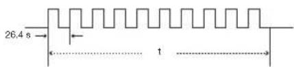
• t = 264 μs • Pulse carrier frequency = 37.917 kHz
• T0 = 1.05 ms • Duty ratio = 1:1
- T1 = 2.10 ms
Transmission control code
15 bit Example of Reverse D to D
| C1 C2 C3 C4 C5 C6 C7 C8 C9 C10 C11 C12 C13 C14 C15 | ||||||
| System Address | Function Key Data Bit | Data Expansion | Mask | Data Determination | ||
| D to D Common Data Bit | ......Reverse in D | |||||
| D | C1 | C2 | C3 | C4 | C5 | C6 | C7 | C8 | C9 | C10 | C11 | C12 | C13 | C14 | C15 |
| 1 | 0 | 1 | 1 | 0 | 1 | 0 | 0 | 0 | 0 | 0 | 0 | 0 | 1 | 0 |
Computer Compatibility Chart
Computer
• Multiple signal support
Horizontal Frequency: 15–81 kHz, Vertical Frequency: 43–100 Hz, Pixel Clock: 12–150 MHz
- Compatible with sync on green and composite sync signals (TTL level)
• AICS (Advanced Intelligent Compression and Expansion System) resizing technology
The following is a list of modes that conform to VESA. However, this projector supports other signals that are not VESA standards.
| PC/MAC | Resolution | Horizontal Frequency (kHz) | Vertical Frequency (Hz) | VESA Standard | DVI Support |
| VGA | 640 × 350 | 27.0 60 | |||
| 31.5 70 | |||||
| 37.9 85 | ✓ | ||||
| 720 × 350 | 27.0 60 | ||||
| 31.5 70 | |||||
| 640 × 400 | 27.0 60 | ✓ | |||
| 31.5 70 | ✓ | ||||
| 37.9 85 | ✓ | ✓ | |||
| 720 × 400 | 27.0 60 | ✓ | |||
| 31.5 70 | ✓ | ||||
| 37.9 85 | ✓ | ✓ | |||
| 640 × 480 | 26.2 50 | ✓ | |||
| 31.5 60 | ✓ | ||||
| 34.7 70 | ✓ | ||||
| 37.9 72 | ✓ | ✓ | |||
| 37.5 75 | ✓ | ✓ | |||
| 43.3 85 | ✓ | ✓ | |||
| 47.9 90 | ✓ | ||||
| 53.0 100 | ✓ | ||||
| SVGA | 800 × 600 | 31.4 50 | ✓ | ||
| 35.1 56 | ✓ | ✓ | |||
| 37.9 60 | ✓ | ✓ | |||
| 44.5 70 | ✓ | ||||
| 48.1 72 | ✓ | ✓ | |||
| 46.9 75 | ✓ | ✓ | |||
| 53.7 85 | ✓ | ✓ | |||
| 56.8 90 | ✓ | ||||
| 64.0 100 | ✓ | ||||
| XGA | 1024 × 768 | 35.5 43 | ✓ | ||
| 40.3 50 | ✓ | ||||
| 48.4 60 | ✓ | ✓ | |||
| 56.5 70 | ✓ | ✓ | |||
| 60.0 75 | ✓ | ✓ | |||
| 68.7 85 | ✓ | ✓ | |||
| 73.5 90 | ✓ | ||||
| 77.2 96 | ✓ | ||||
| 80.6 100 | ✓ |
| PC/MAC | Resolution | Horizontal Frequency (kHz) | Vertical Frequency (Hz) | VESA Standard | DVI Support |
| SXGA | 1152 × 864 | 55.0 60 | √ | ||
| 66.2 70 | √ | ||||
| 64.1 72 | √ | ||||
| 67.5 75 | √ | √ | |||
| 76.6 80 | √ | ||||
| 1152 × 882 | 54.8 60 | √ | |||
| 65.9 72 | √ | ||||
| 67.4 74 | √ | ||||
| 1280 × 1024 | 64.0 60 | √ | √ | ||
| SXGA+ | 1400 × 1050 | 64.0 60 | √ | ||
| — | 1280 × 720 | 45.0 60 | √ | ||
| WXGA | 1280 × 768 | 47.8 60 | √ | ||
| 1360 × 768 | 47.6 60 | √ | |||
| WSXGA | 1600 × 900 | 55.9 60 | √ | ||
| 1920 × 1080* | 66.8 60 | ||||
| MAC 13" | 640 × 480 | 34.9 67 | |||
| MAC 16" | 832 × 624 | 46.8 75 | |||
| 49.6 75 | |||||
| MAC 19" | 1024 × 768 | 48.4 60 | |||
| 60.0 75 | |||||
| MAC 21" | 1152×870 68.5 75 |
* When a 1920 x 1080 signal is input, the image is compressed before it is displayed on the screen.

Note
- This projector may not be able to display images from notebook computers in simultaneous (CRT/LCD) mode. Should this occur, turn off the LCD display on the notebook computer and output the display data in "CRT only" mode. Details on how to change display modes can be found in your notebook computer's operation manual.
- When this projector receives 640 × 350 VESA format VGA signals, "640 × 400" appears on the screen.
- When projecting moving image of interlace signals using RGB input, the intended image may not be projected depending on the signal types. In such cases, use the component, S-video or video input.
DTV
| Signal | Horizontal Frequency (kHz) | Vertical Frequency (Hz) HDMI Support | |
| 480I 15.8 60 | √ | ||
| 480P 31.5 60 | √ | ||
| 576I 15.6 50 | √ | ||
| 576P 31.3 50 | √ | ||
| 720P 45.0 60 | √ | ||
| 720P 37.5 50 | √ | ||
| 1080I 33.8 60 | √ | ||
| 1080I 28.1 50 | √ | ||
| 1080P^* 62.5 50 | √ | ||
| 1080P^* 67.4 60 | √ | ||
* True display when "RESIZE" is set to "DOT BY DOT"
| Problem Check Page | ||
 No picture and no sound or projector does not start No picture and no sound or projector does not start | Projector power cord is not plugged into the wall outlet. | 25 |
| Power to the external connected devices is off. | - | |
| The selected input mode is wrong. | 27 | |
| Cables incorrectly connected to rear panel of the projector. | 18-25 | |
| Remote control batteries have run out. | 11 | |
| External output has not been set when connecting notebook computer. | - | |
| The cover of the lamp unit is not installed correctly. | 49,50 | |
| The selected “Signal Type” is wrong. | 44 | |
| The video signal format of the video equipment is not set correctly. | 43 | |
| “Bright” is set to minimum position. | 29,36 | |
 Color is faded or poor. Color is faded or poor. | Picture adjustments are incorrectly set. | 36 |
| (S-VIDEO or VIDEO input)Video input system is incorrectly set.(COMPONENT, DVI or HDMI input)Input signal type is incorrectly set. | 4344 | |
 Picture is blurred; noise appears. Picture is blurred; noise appears. | Adjust the focus. | 27 |
| The projection distance exceeds the focus range. | 16 | |
| (Computer input)Perform “Fine Sync” Adjustments (“Clock” Adjustment)Perform “Fine Sync” Adjustments (“Phase” Adjustment)Noise will appear depending on the computer. | 4141- | |
| The “DNR” (Digital Noise Reduction) setting is not correct. | 38 | |
| There is fog on the lens. If the projector is carried from a cold room into a warm room, or if it is suddenly heated, condensation may form on the surface of the lens and the image will become blurred. Please set up the projector at least one hour before it is to be used. If condensation should form, remove the power cord from the wall outlet and wait for it to clear. | - | |
| An unusual sound is occasionally heard from the cabinet. | If the picture is normal, the sound is due to cabinet shrinkage caused by a room temperature changes. This will not affect operation or performance. | - |
| Maintenance indicator on the projector illuminates. | See “Maintenance Indicators/Maintenance”. | 46 |
| Power indicator and lamp indicator do not come on while projecting. | “LED” is set to “Off”. | 43 |
| Picture is green when receiving component signals and the signal type setting is set to COMPONENT/RGB 1 or 2. | Change the input signal type setting. | 44 |
| Picture is pink when receiving RGB signals and the signal type setting is set to COMPONENT/RGB 1 or 2. | ||
| The black levels of the image show banding or appear faded when HDMI1 or 2 is selected. | Make adjustments that result in the best picture quality in the “Dynamic Range” setting. | 44 |
| Picture is too bright and whitish. | Picture adjustments are incorrectly set. | 36 |
| The cooling fan becomes noisy. | When temperature inside the projector increases, the cooling fan runs faster. | - |
| The lamp does not light up even after the projector turns on. | The lamp indicator is illuminating in red.Replace the lamp. | 46,49 |
| The lamp suddenly turns off during projection. | ||
| The image sometimes f l ickers. | Cables incorrectly connected to the projector or the connected equipment works improperly.If this happens frequently, replace the lamp. | 18-2449 |
| The lamp needs much time to turn on. | The lamp will eventually need to be changed.While the remaining lamp life draws to a close, replace the lamp. | 49 |
| Picture is dark. | ||
| A response code cannot be received when the projector was attempted to be controlled using RS-232C commands from a computer during standby. | In the case of transmitting RS-232C commands from a computer during standby, it takes a maximum of 30 seconds for the computer to receive the response code. Set the response code waiting time of the computer to 30 seconds or more. | 52 |
| The remote control cannot be used. | Operate the remote control while pointing it at the projector's remote control sensor.The remote control may be too far away from the projector.If direct sunlight or a strong fl uorescent light is shining on the projector's remote control sensor, place the projector where it will not be affected by strong light. | 111111 |
| The batteries may be depleted or inserted incorrectly. Make sure the batteries are inserted correctly or insert new ones. | 11 | |
This unit is equipped with a microprocessor. Its performance could be adversely affected by incorrect operation or interference. If this should happen, unplug the Unit and plug it in again after more than 5 minutes.
Specifications
| Product type | Projector |
| Model | XV-Z21000 |
| Video system | NTSC 3.58/NTSC 4.43/PAL/PAL-M/PAL-N/PAL 60/SECAMDTV480I/DTV480P/DTV720P/DTV1080I/DTV1080P |
| Display method | DLP® chip |
| DLP® panel | Panel size: 0.95"No. of dots: 2,073,600 dots (1,920 [H] × 1,080 [V]) |
| Lens | 1-1.35 × zoom lens, F2.5-8, f = 38.9-52.4 mm |
| Projection lamp | 220 W SHP lamp |
| Video input signal | RCA Connector: VIDEO (VIDEO), composite video, 1.0 Vp-p, sync negative, 75 Ω terminated |
| S-video input signal | 4-pin Mini DIN connector (S-VIDEO)Y (luminance signal): 1.0 Vp-p, sync negative, 75 Ω terminatedC (chrominance signal): Burst 0.286 Vp-p, 75 Ω terminated |
| Component input signal | RCA Connector (COMPONENT/RGB1, 2)Y: 1.0 Vp-p, sync negative, 75 Ω terminatedPb: 0.7 Vp-p, 75 Ω terminatedPr: 0.7 Vp-p, 75 Ω terminated |
| Analog RGB/Digital input signal | 29-pin DVI-I terminal (DVI)<Digital>Input impedance 50 ΩInput level 250-1000 mV<Analog Animation Impedance 75 ΩInput level 0.7 Vp-p< Synchronization signal>Separate sync / Composite syncInput level TTL levelInput impedance 1 KΩGreen on syncInput level (Synchronizing input) 0.286 Vp-pInput Impedance 75 Ω |
| HDMI input signal | HDMI terminal (Video signal only) |
| TRIGGER terminal | Power jack: DC 12 V output |
| Computer control signal | 9-pin D-sub connector (RS-232C Terminal) |
| Horizontal resolution | 520 TV lines (NTSC 3.58 input), 750 TV lines (DTV 720P input) |
| Pixel clock | 12-150 MHz |
| Vertical frequency | 43-100 Hz |
| Horizontal frequency | 15-81 kHz |
| Rated voltage | AC 100-240 V |
| Input current | 3.3 A (When using AC 100 V) |
| Rated frequency | 50/60 Hz |
| Power consumption | 320 W (Lamp Setting "Bright")/265 W (Lamp Setting "Eco + Quiet") with AC 100 V310 W (Lamp Setting "Bright")/260 W (Lamp Setting "Eco + Quiet") with AC 240 V |
| Power consumption (standby) | 0.1 W (AC 100 V, RS-232C OFF) - 0.18 W (AC 240 V, RS-232C OFF) |
| Heat dissipation | 1,200 BTU/hour |
| Operating temperature | 41°F to 95°F (+5°C to +35°C) |
| Storage temperature | -4°F to 140°F (-20°C to +60°C) |
| Cabinet | Plastic |
| I/R carrier frequency | 38 kHz |
| Dimensions (approx.) | 1811/16" × 651/64" × 165/32" (475 (W) × 172.5 (H) × 410.2 (D) mm) (main body only) |
| Weight (approx.) | 20.7 lbs. (9.4 kg) |
| Replacement parts | Remote control, Power cord for Europe, except U.K., Power cord for U.K. and Singapore, Power cord for Australia, New Zealand and Oceania, 21 pin RCA conversion adaptor, Video cable, DVI to D-sub cable, Lens cap, Terminal cover, Projector operation manual |
As a part of policy of continuous improvement, SHARP reserves the right to make design and specification changes for product improvement without prior notice. The performance specification figures indicated are nominal values of production units. There may be some deviations from these values in individual units.
Dimensions
Units: inch (mm)


Accessories 4
AC socket 25
Adjustment buttons 34
Adjustment feet 28
Advanced 37
All Reset 45
Automatic Contrast 39
Auto Power Off 45
Auto Sync 41
AUTO SYNC button 41
Background 44
Batteries 11
Black Level 43
Bright....36
BRIGHT button 29
BrilliantColor™ 38
Ceiling-mount setup 15
CINEMA ZOOM 31
Clock 41
CLR Temp (Color Temperature) 36
C.M.S. 37
Color....36
Color Space 44
COMPONENT/RGB 1 terminal 20, 21
COMPONENT/RGB 2 terminal 20, 21
Contrast......36
CONTRAST button 29
DNR....38
DOT BY DOT 31
DVI terminal 18-20, 23
Dynamic Range 44
Economy Mode 44
ENTER button 34
Fan Mode 45
Film Mode 38
Fine Sync 41
Focus ring 27
FREEZE button 29
Gamma....40
Gamma Position 37,40
HDMI1 terminal 18
HDMI2 terminal 18
H-Pos 41
Hue 37
Image Shift 42
INPUT button 27
Input Mode Select buttons 27
IRIS....37
IRIS button 29
Kensington Security Standard connector 9
Lamp indicator 46
Lamp Setting 37
Lamp Timer (Life) 43
Language (on-screen display language) 45
LED 43
Lens cap 8
Lens shift dial 28
LIGHT button 10
MENU button 34
MNR 38
ON button 25
Options 42
Optional accessories 4
On-screen Display 43
Overscan 42
Phase 41
Picture 36
Picture Mode 36
PICTURE MODE button 29
Power cord 25
Power indicator 25,46
PRJ mode 15,45
Progressive....38
Remote control 10
Remote control sensor 11
Replacing the lamp 48
RESIZE button 30
RETURN button 34
RGB/COMP. button 44
RS-232C....45
RS-232C Port 44
RS-232C terminal 24
Saturation 37
Sharp....36
SIDE BAR 30
Signal Info 41
Signal Type 44
SMART STRETCH 30
SMART ZOOM 31
Special Modes 41
STANDBY button 26
STRETCH 30
Subtitle 42
S-VIDEO terminal 22
Temperature warning indicator 46
Tint 36
TRIGGER terminal 9
Unveil Control 39
Value....37
Video System 43
VIDEO terminal 22
V-Pos....41
White Level 43
WIRED R/C JACK 10
WIRED REMOTE control input terminal 10
ZOOM 14:9 31
Zoom knob 27
SHARP®
- SPECIAL NOTE FOR USERS IN THE U.K
- DANGER
- WARNING
- IMPORTANT
- INTRODUCTION
- CAUTION
- PRODUCT DISPOSAL
- CAUTION CONCERNING LAMP REPLACEMENT
- PREPARING
- QUICK START
- SETUP
- CONNECTIONS
- USING
- BASIC OPERATION
- USEFUL FEATURES
- REFERENCE
- APPENDIX
- SUPPLIED ACCESSORIES
- OPTIONAL ACCESSORIES
- NOTE
- MARKS USED IN THIS OPERATION MANUAL
- INFO
- FOR FUTURE REFERENCE
- AND
- ND
- READ INSTRUCTIONS
- RETAIN INSTRUCTIONS
- HEED WARNINGS
- FOLLOW INSTRUCTIONS
- CLEANING
- ATTACHMENTS
- WATER AND MOISTURE
- ACCESSORIES
- TRANSPORTATION
- VENTILATION
- POWER SOURCES
- GROUNDING OR POLARIZATION
- POWER-CORD PROTECTION
- LIGHTNING
- OVERLOADING
- OBJECT AND LIQUID ENTRY
- SERVICING
- DAMAGE REQUIRING SERVICE
- REPLACEMENT PARTS
- SAFETY CHECK
- WALL OR CEILING MOUNTING
- HEAT
- OBSERVE THE FOLLOWING SAFEGUARDS WHEN SETTING UP YOUR PROJECTOR
- CAUTION CONCERNING THE LAMP UNIT
- CAUTION CONCERNING THE SETUP OF THE PROJECTOR
- DO NOT SET UP THE PROJECTOR IN PLACES EXPOSED TO DIRECT SUNLIGHT OR BRIGHT LIGHT
- CAUTION REGARDING PLACING OF THE PROJECTOR
- WHEN USING THE PROJECTOR IN HIGH-ALTITUDE AREAS SUCH AS MOUNTAINS (AT ALTITUDES OF APPROXIMATELY 4,900 FEET (1,500 METERS) OR MORE)
- WARNING ABOUT PLACING THE PROJECTOR IN A HIGH POSITION
- DO NOT SUBJECT THE PROJECTOR TO HARD IMPACT AND/OR VIBRATION
- REST YOUR EYES OCCASIONALLY
- AVOID LOCATIONS WITH EXTREMES OF TEMPERATURE
- DO NOT BLOCK THE EXHAUST AND INTAKE VENTS
- CAUTION REGARDING USAGE OF THE PROJECTOR
- OTHER CONNECTED EQUIPMENT
- USING THE PROJECTOR IN OTHER COUNTRIES
- TEMPERATURE MONITOR FUNCTION
- TEMP
- PART NAMES AND FUNCTIONS
- PROJECTOR
- USING THE TERMINAL COVER
- ATTACHING THE TERMINAL COVER
- USING THE KENSINGTON LOCK
- CONNECTING THE REMOTE CONTROL TO THE PROJECTOR
- USING THE REMOTE CONTROL
- INSERTING THE BATTERIES
- USABLE RANGE
- WHEN USING THE REMOTE CONTROL
- INCORRECT USE OF THE BATTERIES MAY CAUSE THEM TO LEAK OR EXPLODE. PLEASE FOLLOW THE PRECAUTIONS BELOW
- PLACE THE PROJECTOR FACING A SCREEN
- CONNECT THE PROJECTOR TO THE VIDEO EQUIPMENT AND PLUG THE POWER CORD INTO THE AC SOCKET OF THE PROJECTOR
- REMOVE THE LENS CAP AND TURN THE PROJECTOR ON
- TURN THE VIDEO EQUIPMENT ON AND START PLAYBACK
- SELECT THE INPUT MODE
- ADJUST THE PROJECTOR ANGLE, FOCUS AND ZOOM
- TURN THE POWER OFF
- SETTING UP THE PROJECTOR
- STANDARD SETUP (FRONT PROJECTION)
- EXAMPLE OF STANDARD SETUP
- PROJECTION (PRJ) MODE
- CEILING-MOUNT SETUP
- INDICATION OF THE PROJECTION IMAGE SIZE AND PROJECTION DISTANCE
- PICTURE (SCREEN) SIZE AND PROJECTION DISTANCE
- SAMPLES OF CABLES FOR CONNECTION
- CONNECTING TO VIDEO EQUIPMENT
- CONNECTING EQUIPMENT WITH HDMI OUTPUT TERMINAL TO THE HDMI TERMINAL ON THE PROJECTOR
- CONNECTING EQUIPMENT WITH THE HDMI OUTPUT TERMINAL TO THE DVI TERMINAL ON THE PROJECTOR
- CONNECTING TO VIDEO EQUIPMENT (CONTINUED)
- CONNECTING TO A COMPUTER
- CONTROLLING THE PROJECTOR BY A COMPUTER
- TURNING THE PROJECTOR ON/OFF
- CONNECTING THE POWER CORD
- TURNING THE PROJECTOR ON
- TURNING THE POWER OFF (PUTTING THE PROJECTOR INTO STANDBY MODE)
- IMAGE PROJECTION
- SWITCHING THE INPUT MODE
- ADJUSTING THE PROJECTED IMAGE
- ADJUSTING THE FOCUS
- ADJUSTING THE IMAGE SIZE
- ADJUSTING THE PROJECTOR ANGLE USING THE ADJUSTMENT FEET
- ADJUSTING THE VERTICAL POSITION OF THE IMAGE
- OPERATING WITH THE REMOTE CONTROL
- SWITCHING THE IRIS SETTING
- ADJUSTING THE CONTRAST
- ADJUSTING THE QUANTITY OF LIGHT
- FREEZING A MOVING IMAGE
- SELECTING THE PICTURE MODE
- SELECTING THE SCREEN SIZE
- RESIZE MODE
- ABOUT COPYRIGHTS
- USING THE MENU SCREEN
- MENU SELECTIONS (ADJUSTMENTS)
- TO ADJUST THE PROJECTED IMAGE WHILE VIEWING IT
- PRESS ⏻ ENTER
- PRESS ▶ OR ◀ TO ADJUST THE ITEM SELECTED
- PRESS ⓄMENU
- PICTURE ADJUSTMENT ("PICTURE" MENU)
- ①SELECTING THE PICTURE MODE
- ②ADJUSTING THE IMAGE
- SELECTING THE GAMMA POSITION
- LAMP SETTING
- USING THE ADVANCED
- ADJUSTING THE COLORS
- ⑧ ADJUSTING THE BRILLIANTCOLOR™
- ⑨ SELECTING THE PROGRESSIVE MODE
- ⑩ SELECTING THE FILM MODE
- ⑪ REDUCING IMAGE NOISE (DNR)
- ⑫MOSQUITO NOISE REDUCTION (MNR)
- ADJUSTING THE UNVEIL CONTROL
- ADJUSTING THE AUTOMATIC CONTRAST
- RESETTING ALL ADJUSTMENT ITEMS
- GAMMA ADJUSTMENT ("GAMMA" MENU)
- ① SELECTING THE GAMMA POSITION
- ② ADJUSTING THE GAMMA
- COMPUTER IMAGE ADJUSTMENT ("FINE SYNC" MENU)
- ① ADJUSTING THE COMPUTER IMAGE
- ② SPECIAL MODES SETTING
- ③ CHECKING THE INPUT SIGNAL
- ④ AUTO SYNC (AUTO SYNC ADJUSTMENT)
- USING THE "OPTIONS" MENU
- ① ADJUSTING THE IMAGE POSITION
- ② ADJUSTING THE VERTICAL SIZE OF THE DISPLAY (SUBTITLE SETTING)
- ③ ADJUSTING THE OVERSCAN
- ④ ADJUSTING THE WHITE LEVEL/BLACK LEVEL
- ⑤ TURNING LED OFF
- ⑥ CHECKING THE LAMP LIFE STATUS
- ⑦ SETTING ON-SCREEN DISPLAY
- ⑧ SETTING THE VIDEO SYSTEM
- ⑧ SIGNAL TYPE SETTING
- WHEN COMPONENT IS SELECTED FOR THE INPUT MODE
- WHEN DVI IS SELECTED FOR THE INPUT MODE
- WHEN HDMI IS SELECTED FOR THE INPUT MODE
- ⑨ ADJUSTING THE COLOR SPACE
- ⑩ ADJUSTING THE DYNAMIC RANGE
- ⑪ SELECTING THE BACKGROUND IMAGE
- ⑫ ADJUSTING THE ECONOMY MODE
- RS-232C PORT
- AUTO POWER OFF
- SELECTING THE TRANSMISSION SPEED (RS-232C)
- FAN MODE SETTING
- REVERSING/INVERTING PROJECTED IMAGES
- RETURNING TO THE DEFAULT SETTINGS
- OTHER FUNCTION
- SELECTING THE ON-SCREEN DISPLAY LANGUAGE
- MAINTENANCE INDICATORS/MAINTENANCE
- ABOUT THE TEMPERATURE WARNING INDICATOR
- ABOUT THE LAMP INDICATOR
- CLEANING THE PROJECTOR
- CLEANING THE LENS
- CLEANING THE EXHAUST AND INTAKE VENTS
- REGARDING THE LAMP
- LAMP
- CAUTION CONCERNING THE LAMP
- REPLACING THE LAMP
- REMOVING AND INSTALLING THE LAMP UNIT
- REGARDING THE LAMP (CONTINUED)
- INSERT THE NEW LAMP UNIT
- ATTACH THE LAMP UNIT COVER
- RESETTING THE LAMP TIMER
- CONNECT THE POWER CORD
- RESET THE LAMP TIMER
- CONNECTING PIN ASSIGNMENTS
- RS-232C TERMINAL: 9-PIN D-SUB MALE CONNECTOR
- RS-232C SPECIFICATIONS AND COMMAND SETTINGS
- PC CONTROL
- COMMUNICATION CONDITIONS
- BASIC FORMAT
- COMMANDS
- WIRED REMOTE CONTROL TERMINAL SPECIFICATIONS
- SPECIFICATIONS OF WIRED REMOTE CONTROL INPUT
- SHARP REMOTE CONTROL SIGNAL FORMAT
- TRANSMISSION CONTROL CODE
- COMPUTER COMPATIBILITY CHART
- COMPUTER
- SPECIFICATIONS
- DIMENSIONS
- SHARP®
Brand : SHARP
Model : XV-Z21000
Category : Projector