
PELLKAMIN 8 EVO2 - Fireplace EDILKAMIN - Free user manual and instructions
Find the device manual for free PELLKAMIN 8 EVO2 EDILKAMIN in PDF.


| Product Type | Pellet Fireplace Insert |
| Model | PELLKAMIN 8 EVO2 |
| Brand | Edilkamin |
| Heating Power (Nominal) | 8 kW |
| Heated Area (Approx.) | Up to 200 m² |
| Fuel Type | Wood Pellets (6 mm diameter, ENplus A1) |
| Hopper Capacity | Approx. 20 kg |
| Autonomy (Max) | Up to 24 hours at low power |
| Dimensions (W x H x D) | 595 x 1140 x 535 mm |
| Weight | 115 kg |
| Electrical Supply | 230 V / 50 Hz |
| Power Consumption (Ignition/Running) | 400 W / 80-140 W |
| Flue Outlet Diameter | 80 mm horizontal or vertical |
| Efficiency | > 90% |
| Emissions (CO, mg/Nm³) | < 200 |
| Control System | Digital microprocessor with remote control |
| Programming Functions | Weekly timer, on/off, power levels |
| Safety Features | Thermal safety switch, safety thermostat, flue gas fan control |
| Maintenance | Daily ash removal, periodic cleaning of heat exchanger |
| Certifications | CE, EN 13240, Ecodesign ready |
Frequently Asked Questions - PELLKAMIN 8 EVO2 EDILKAMIN
User questions about PELLKAMIN 8 EVO2 EDILKAMIN
0 question about this device. Answer the ones you know or ask your own.
Ask a new question about this device
Download the instructions for your Fireplace in PDF format for free! Find your manual PELLKAMIN 8 EVO2 - EDILKAMIN and take your electronic device back in hand. On this page are published all the documents necessary for the use of your device. PELLKAMIN 8 EVO2 by EDILKAMIN.
USER MANUAL PELLKAMIN 8 EVO2 EDILKAMIN
PELLKAMIN 8 EVO2 PELLKAMIN 10+ EVO2
MANUAL installation use maintenance digital

EDILKAMIN
- NOTE ON EDITION AND LANGUAGE....5
1.1. Note on the language of the manual 5
1.2. Digital online edition 5
-
CE MARKING INFORMATION......6
-
INTRODUCTION....7
3.1. Recipients of the manual....7
3.2. General notes 7
3.3. Meaning of the symbols 7
3.4. Product identification and warranty 8
3.5. CE plate: Data and position 9
3.6. Symbols on data plate....10
- SAFETY INFORMATION 11
4.1. General notes for the safe use of the product....11
4.2. Recommendations and prohibitions for the safe use of the product....12
4.3. Possible risks if the installation, operation and maintenance instructions are not followed....13
- DIMENSIONS....14
5.1. Pellkamin 8 Evo2....14
5.2. Pellkamin 10+ Evo2 15
5.3. Pellet loading hatch 16
5.4. Pellet loading drawer 17
5.5. Support frame....17
- TECHNICAL DATA....18
6.1. Technical data according to the product standard 18
6.2. Technical data according to the product standard 19
6.3. Technical data for sizing the chimney system....20
6.4. Electrical data....21
6.5. ECODESIGN technical data Pellkamin 8 Evo2....22
6.6. ECODESIGN technical data Pellkamin 10+ Evo2 24
- UNPACKING....26
7.1. Notes on unpacking....26
7.2. Packaging disposal instructions 27
72 Remove from the pallet

EDILKAMIN
10. INSTRUCTIONS FOR USE 48
10.1. Training before use 49
10.2. Steps for the first start-up
10.3. Loading pellets into the hopper 50
10.3.1. Extraction on slide rails (PRODUCT IS OFF) 50
11. INTERFACE AND OPERATING MODES 52
11.1. Operating modes 52
11.2. Interface....53
12. OPTIONAL PROBES/THERMOSTATS CONNECTIONS 54
12.1. Remote control 55
12.1.1. Remote control energy saving 56
12.2. First power supply 58
12.3. Possible states of the product 58
12.4. Switch on screen 59
12.5. AUTOMATIC and MANUAL setting 60
12.6. Ventilation....61
12.6.1. With optional room probe (for products with ducting) 62
12.7. RELAX function 63
12.8. EASY TIMER function (delayed switch on and switch off)....63
12.9. CHRONO....64
12.10. Menu....64
12.10.1. How to access the menus....65
12.10.2. Stand-By 66
12.10.3. Access to the Menu and setting 66
12.10.4. Pellet load 68
12.10.5. Chrono prog. 69
12.10.6. Chrono temp. (T1-T2) 70
12.10.7. Date and time....71
12.10.8. Language 72
12.10.9. Display 73
12.10.10. Info 74
12.10.11. Software 76
12.10.12. Data 77
12.10.13. Alarms....78
12.10.14. Pellet drop....78

EDILKAMIN
- ADVICE FOR POSSIBLE PROBLEMS....97
16.1. Display messages 97
16.2. Remote control battery level low 99
16.3. Maintenance (message that does not cause switch-off) 99
16.4. No communication....100
16.5. Pellet reserve light (where the sensor is present) 100
16.6. Black-out....101

EDILKAMIN
1. NOTE ON EDITION AND LANGUAGE
1.1. Note on the language of the manual
Original edition in Italian. Manuals in other languages are translated from the original manual in Italian.
1.2. Digital online edition
Dear Customer/Installer
Please read this document carefully together with the user manual which can be found inside our product.
The information contained in it are suggestions which in no way replace the responsibility of the installer - maintenance technician.
All local and national laws and European Standards must be complied with as regards the correct sizing, installation, maintenance and use of the product.
For installation and for anything not expressly mentioned, please refer to local and national regulations in the country where the product is used.
The diagrams in this manual are purely indicative and in no way can the company be held liable.
How to download the manual:
- access the download area, www.edilkamin.com
- click on "Installation, use and maintenance manual".
- Select the language, the product type and the product name from the drop-down lists.
- Click on "download" to download the manual in pdf.

This document may be subject to changes dictated by the Manufacturer or by the regulations in force at the time of purchase.
The updated version that is currently in force will always be available from the download area of the website edilkamin.com.

Before move the product, it is better empty stock

EDILKAMIN
2. CE MARKING INFORMATION
The writer EDILKAMIN S.p.a., with registered office in Via P. Moscati 8 - 20154 Milan - Fiscal Code/VAT No. 00192220192, declares under its own responsibility that the products shown on the cover comply with EU Regulation 305/2011 and with the harmonised European product standard in force
The declaration of performance is available on the website www.edilkamin.com
It also declares that:
the products shown on the cover meet the requirements (where applicable) of the following European Directives:
2014/35/EU-Low Voltage Directive (for products with electrical components)
2014/30/EU-Electromagnetic Compatibility Directive (for products with electrical components)
2014/53/EU:RED (for products with radio remote control)
2011/65/EU-RoHS Directive
2009/125/EU-Ecodesign
2010/30/EU-Labelling

EDILKAMIN
3. INTRODUCTION
USER/INSTALLER
Dear Madam / Sir
We thank you and congratulate you for choosing our product. Please keep the manual for the entire service life of the product. If lost, ask your retailer for a copy or download it from the download area on the website www.edilkamin.com
3.1. Recipients of the manual
This manual is for:
- the person who uses the product at home ("USER")
- the technician who installs the product ("INSTALLER") who can find other material on the website
The recipient of the chapter (USER/INSTALLER) is indicated at the start of the chapter
3.2. General notes
After unpacking the product, check the integrity and completeness of the contents.
If any anomalies are found, immediately contact the retailer from whom it was purchased, to whom a copy of the warranty certificate and of the tax document must be given.
All local and national laws and European Standards must be complied with as regards the correct sizing, installation, maintenance and use of the appliance. For installation, maintenance and for anything not expressly mentioned, please refer to the local regulations in force in the country where the product is used.
The diagrams in this manual are purely indicative: they do not always strictly refer to the specific product and in no case are they contractual.
3.3. Meaning of the symbols

PROHIBITION:
Indication of operations that must NOT be performed, to avoid damage.

EDILKAMIN
3.4. Product identification and warranty.
The product is uniquely identified by a number, the "warranty slip or serial number" which can be found on the warranty certificate. Please keep:
• The warranty certificate that you found in the product
• The tax document issued by the retailer
- The declaration of conformity issued by the installer. Check local and national regulations.
The warranty conditions are indicated in the warranty certificate which can be found in the product and on the website www.edilkamin.com


This document may be subject to changes dictated by the Manufacturer or by the regulations in force at the time of purchase.
The updated version that is currently in force will always be available from the download area of the website edilkamin.com.

EDILKAMIN
3.5. CE plate: Data and position

We recommend taking a photo of the CE plate, which shows the data according to the harmonised product standard and the warranty slip (serial number), for all required uses.
The CE plate can be found on the left side of the product

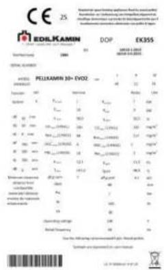

THE DRAWINGS ARE INDICATIVE. THEY ARE USEFUL FOR ASSEMBLY, BUT THEY DO NOT ALWAYS REFER TO THE SPECIFIC MODEL.

EDILKAMIN
3.6. Symbols on data plate
| Symbols | Description |
| Pw nom | Rated water power |
| Pw part | Reduced water power |
| η nom | Rated yield |
| η part | Reduced yield |
| CO nom (13%O2) | Rated CO |
| CO part (13%O2) | CO ridotta |
| Nox nom (13%O2) | Reduced CO |
| Nox part (13%O2) | Rated NOX |
| OGC nom (13%O2) | Rated OGC |
| OGC part (13%O2) | Reduced OGC |
| PM nom (13%O2) | Rated dust emissions |
| PM part (13%O2) | Reduced dust emissions |
| p nom | Rated power |
| p part | Reduced power |
| T nom | Rated smoke temperature |
| T part | Reduced smoke temperature |
| φf.g nom | Rated mass flow rate |
| φf.g part | Reduced mass flow rate |
| dout | Fume outlet diameter |
| Pw | Maximum pressure |
| W | Rated electrical power according to EN 60335 |

4. SAFETY INFORMATION
USER/INSTALLER

The characters of the safety information are larger according to the standards
4.1. General notes for the safe use of the product
For the safe use of the product, carefully read the operating instructions section of the manual.
If something is not clear, do not act on your own initiative but contact the retailer or the installer. The names of Edilkamin's contracted and licensed technical service centres are available ONLY at www.edilkamin.com
The product is not designed to be used by people, including children, with reduced physical, sensory or mental capabilities.
This appliance can be used by children aged from 8 years and above and persons with reduced physical, sensory or mental capabilities or lack of experience and knowledge if they have been given supervision or instruction concerning use of the appliance in a safe way and

The product is designed to operate only with the covers fitted. Otherwise there is a risk of accessible live parts.
4.2. Recommendations and prohibitions for the safe use of the product
Use the product only after it has been installed by qualified technicians in a workmanlike manner and in accordance with local and national regulations.
Power up the product only after it has been fully assembled and the covers have been fitted.
Do not install in rooms where there is a risk of fire. There is a risk of damage to property and people.
Do not touch hot parts and, when the product is off but still hot, use suitable precautions (e.g. fire resistant gloves).
Do not access internal parts. When it is connected to the electrical power supply, there is a risk of electric shock.
Do not ignite or stoke the flame with liquid sprays or flame throwers. There is a risk of serious burns and damage to property and people.
Do not burn waste, plastic materials or anything other than wood pellets. There is a risk of soiling the product, causing a fire in the

EDILKAMIN
Do not keep any type of flammable liquid near the product. There is a risk of fire.
Do not block the ventilation openings in the room or the air inlets or chimney. There is a risk of smoke entering the room with the risk of causing damage to property and people.
Do not use the product as a support or as a ladder. There is a risk of damage to property and people.
Do not attempt to use the product with the door open or throw hot material out of the product. There is a risk of fire.
Do not use the product if the glass is broken.
Do not use water in case of fire and contact your local authorities.
4.3. Possible risks if the installation, operation and maintenance instructions are not followed
Risk of BURNS in case of contact with hot parts.
Risk of ELECTRIC SHOCK in case of contact with internal parts when connected to the electrical power supply.
Risk of INJURY to hands if used carelessly or by people with reduced skills, if the safety devices are removed or if access to the internal parts

EDILKAMIN
5. DIMENSIONS
USER/INSTALLER
A: smoke outlet
B: combustion air inlet
C: air outlet for ducting (if present)
D: delivery (for hydro products)
E: return (for hydro products)
F: load (for hydro products)
Dimensions in cm
5.1. Pellkamin 8 Evo2


EDILKAMIN
A: smoke outlet
B: combustion air inlet
C: air outlet for ducting (if present)
D: delivery (for hydro products)
E: return (for hydro products)
F: load (for hydro products)
Dimensions in cm
5.2. Pellkamin 10+ Evo2


EDILKAMIN
5.3. Pellet loading hatch


EDILKAMIN
5.4. Pellet loading drawer


5.5. Support frame
A support frame for installation as a firebox is available as an optional accessory
6. TECHNICAL DATA
USER/INSTALLER
6.1. Technical data according to the product standard
The data shown is indicative and obtained during the certification phase at a notified body according to current regulations.
The results were obtained with the glass cleaning air closed. It is the responsibility of the installer to use the gasket supplied and to adjust the parameters.
| Quantity | |||
| PELLKAMIN 8 EVO2 | |||
| Rated power | Reduced power | ||
| Output power | 8 | 4 | kW |
| Yield | 91,9 | 92,5 | % |
| CO emissions at 13% O2 | 0,015 | 0,020 | % |
| Smoke temperature | 134 | 99 | °C |
| Fuel consumption | 1,8 | 0,9 | kg/h |
| Hopper capacity | 11 | kg | |
| Draught | 12,4 | 11,3 | Pa |
| Autonomy | 7 | 13 | Hours |
| Minimum volume of installation room | 40 | m3 | |
| Heatable volume | 210 | m3 | |
| Smoke duct diameter | 80 | mm |

EDILKAMIN
6.2. Technical data according to the product standard
The data shown is indicative and obtained during the certification phase at a notified body according to current regulations.
The results were obtained with the glass cleaning air closed. It is the responsibility of the installer to use the gasket supplied and to adjust the parameters.
| Quantity | |||
| PELLKAMIN 10+ EVO2 | |||
| Rated power | Reduced power | ||
| Output power | 10 | 4 | kW |
| Yield | 90,9 | 92,5 | % |
| CO emissions at 13% O2 | 0,015 | 0,020 | % |
| Smoke temperature | 157,7 | 99 | °C |
| Fuel consumption | 2,3 | 0,9 | kg/h |
| Hopper capacity | 11 | kg | |
| Draught | 12,1 | 11,3 | Pa |
| Autonomy | 5 | 12 | Hours |
| Minimum volume of installation room | 40 | m3 | |
| Heatable volume | 260 | m3 | |
| Smoke duct diameter | 80 | mm | |
| Air intake duct diameter | 40 | mm | |
| Weight with packaging | 155 | kg | |
| Energy efficiency class (Regulation 1185/2015) | A+ |

EDILKAMIN
6.3. Technical data for sizing the chimney system
| Quantity | |||
| PELLKAMIN 8 EVO2 | |||
| Rated power | Reduced power | ||
| CO2 | 9,6 | 6,7 | % |
| Smoke temperature at exhaust | 161 | 119 | °C |
| Minimum draught | 0,01 | Pa | |
| Flue gas flow rate | 6 | 4,1 | g/s |
| Quantity | |||
| PELLKAMIN 10+ EVO2 | |||
| Rated power | Reduced power | ||
| CO2 | 10,4 | 6,7 | % |
| Smoke temperature at exhaust | 189 | 119 | °C |
| Minimum draught | 0,01 | Pa | |
| Flue gas flow rate | 7 | 4,1 | g/s |

The chimney system and the installation as a whole must comply with the instructions given in this manual and with all local and national regulations. The installer is responsible for the installation

EDILKAMIN
6.4. Electrical data
| Quantity | ||
| PELLKAMIN 8 EVO2 | ||
| Power supply | 230 | Vac |
| Frequency | 50 | Hz |
| Rated power consumption | 160 | W |
| Reduced power consumption | 86 | W |
| Power consumption in stand-by | 3 | W |
| Rated electrical power | 180 | W |
| Protection | Fuse 4 AT,250 Vac 5x20 |
| Quantity | ||
| PELLKAMIN 10+ EVO2 | ||
| Power supply | 230 | Vac |
| Frequency | 50 | Hz |
| Rated power consumption | 165 | W |
| Reduced power consumption | 86 | W |
| Power consumption in stand-by | 3 | W |
| Rated electrical power | 185 | W |
| Protection | Fuse 4 AT,250 Vac 5x20 |

The installation must comply with national and local regulations. For safety reasons, the electrical system must comply with legal standards. Correct earthing is essential.

EDILKAMIN
6.5. ECODESIGN technical data Pellkamin 8 Evo2

acteco
| Indirect heating functionality: NO |
| Direct heat output: 8,0 kW (space heat output) |
| Indirect heat output: - kW (water heat output) |
| Fuel | Preferred fuel (only one) | Other suitable fuel(s) | ηp [%] | Space heating emissions at nominal heat output(*) | Space heating emissions at minimum heat output*(*) | ||||||
| PM | OGC | CO | NOx | PM | OGC | CO | NOx | ||||
| mg/m3at 13% O2 | mg/m3at 13% O2 | ||||||||||
| Log wood, moisture content ≤ 25 % | no | no | |||||||||
| Compressed wood with moisture content < 12 % | yes | no | 88,6 | 10 | 2 | 176 | 100 | 5 | 2 | 102 | 117 |
| Other woody biomass | no | no | |||||||||
| Non-woody biomass | no | no | |||||||||

EDILKAMIN

octeco
Characteristics when operating with the preferred fuel only:
Seasonal space heating energy efficiency η s[%] 86,6
| Energy efficiency index EEI: 128 | |||
| Item | Symbol | Value | Unit |
| Heat output | |||
| Nominal heat output | Pfree | 8,0 | kW |
| Minimum heat output (indicative) | Pfree | 4,0 | kW |
| Auxiliary electricity consumption | |||
| At nominal heat output | efree | 0,160 | kW |
| At minimum heat output | efree | 0,086 | kW |
| In standby mode | efree | 0,003 | kW |
| Permanent pilot flame power requirement | |||
| Pilot flame power requirement (if applicable) | Ppilot | N.A. | kW |
Energy efficiency class: A+
| Item | Symbol | Value | Unit |
| Useful efficiency (NCV as received) | |||
| Useful efficiency at nominal heat output | ηp,mm | 91,9 | % |
| Useful efficiency at minimum heat output (indicative) | ηp,ave | 92,5 | % |
| Type of heat output/room temperature control (select one) | |||
| single stage heat output, no room temperature control | NO | ||
| two or more manual stages, no room temperature control | NO | ||
| with mechanic thermostat room temperature control | NO | ||
| with electronic room temperature control | NO | ||
| with electronic room temperature control plus day timer | NO | ||
| with electronic room temperature control plus week timer | YES | ||
| Other control options (multiple selections possible) | |||

EDILKAMIN
6.6. ECODESIGN technical data Pellkamin 10+ Evo2

acteco
Institute and office for behavioral changes, quality of the socialized and uniparous and variousities of the life. However, Artemis is a Traveling event, 41 August, 2010, 15:30, 28 maggi 1990s
ECODESIGN REQUIREMENTS FOR SOLID FUEL LOCAL SPACE HEATERS ACCORDING TO COMMISSION REGULATION (EU) 2015/1185 AND ENERGY LABELLING OF LOCAL SPACE HEATERS ACCORDING TO COMMISSION REGULATION (EU) 2015/1186
EDILKAMIN - PELLKAMIN 10+ EVO2
| Indirect heating functionality: NO |
| Direct heat output: 10.0 kW (space heat output) |
| Indirect heat output: - kW (water heat output) |
| Fuel | Preferred fuel (only one) | Other suitable fuel(s) | η p [%] | Space heating emissions at nominal heat output(*) | Space heating emissions at minimum heat output*( * * ) | ||||||
| PM | OGC | CO | NOx | PM | OGC | CO | NOx | ||||
| mg/m3at 13% O2 | mg/m3at 13% O2 | ||||||||||
| Log wood, moisture content ≤ 25 % | no | no | |||||||||
| Compressed wood with moisture content < 12 % | yes | no | 86,3 | 10 | 4 | 230 | 99 | 5 | 2 | 102 | 117 |
| Other woody biomass | no | no | |||||||||
| Non-woody biomass | no | no | |||||||||

EDILKAMIN

octeco
Characteristics when operating with the preferred fuel only:
Seasonal space heating energy efficiency η s [%]: 86,3
| Energy efficiency index EEI: 127 | Energy efficiency class: A+ | ||||||
| Item | Symbol | Value | Unit | Item | Symbol | Value | Unit |
| Heat output | Useful efficiency (NCV as received) | ||||||
| Nominal heat output | Pheat | 10,0 | kW | Useful efficiency at nominal heat output | ηheat | 90,9 | % |
| Minimum heat output (indicative) | Pmin | 4,0 | kW | Useful efficiency at minimum heat output (indicative) | ηmin | 92,5 | % |
| Auxiliary electricity consumption | Type of heat output/room temperature control (select one) | ||||||
| At nominal heat output | emax | 0,165 | kW | single stage heat output, no room temperature control | NO | ||
| At minimum heat output | emin | 0,086 | kW | two or more manual stages, no room temperature control | NO | ||
| In standby mode | eloss | 0,003 | kW | with mechanic thermostat room temperature control | NO | ||
| Permanent pilot flame power requirement | with electronic room temperature control | NO | |||||
| with electronic room temperature control plus day timer | NO | ||||||
| Pilot flame power requirement (if applicable) | Ppilot | N.A. | kW | with electronic room temperature control plus week timer | YES | ||
| Other control options (multiple selections possible) | |||||||

EDILKAMIN
7. UNPACKING

Only qualified personnel can unpack the product, in accordance with the safety regulations
INSTALLER
7.1. Notes on unpacking
The materials that compose the packaging are neither toxic nor harmful and as such do not require special disposal processes.
Storage, disposal or possibly recycling is the responsibility of the end user in accordance with the applicable laws. The packaging may be different in different countries for regulatory and transport reasons.

Perform all handling operations with the package upright, using suitable equipment and complying with current safety regulations. Do not overturn the package and take great care with the parts to be assembled.

DO NOT LEAVE PACKAGING WITHIN THE REACH OF CHILDREN. Packaging material (e.g. plastic, sheets of film) can be dangerous for children. There is a risk of suffocation.

EDILKAMIN
7.2. Packaging disposal instructions
| Guidance notes:Comply with the local and national regulations |
| DESCRIPTION | INSTRUCTIONS FOR COLLECTION |
| Wooden pallet | Separate collection |
| Wooden crate | Wood |
| Wooden pellet | Check the regulations of the relevant authority |
| Cardboard box | Separate collection |
| Cardboard corner | Paper |
| Appliance bag | Separate collection |
| Accessory bag | Plastic |
| Bubble wrap | Check the regulations of the relevant authority |
| Protective sheet | Check the regulations of the relevant authority |
| Labels | Check the regulations of the relevant authority |
| Polystyrene | Separate collection |
| Straps | Separate collection |
| Adhesive tape | Plastic |
| Hardware | Separate collection |
| Staples for straps | Metal |
| Fixing bracket | Check the regulations of the relevant authority |

EDILKAMIN
7.3. Remove from the pallet
| Do not attempt to remove the product from the pallet before removing the screws. Only qualified personnel can remove the product from the pallet, in accordance with the safety regulations. The installer can find the complete instructions on the website. |
| THE DRAWINGS ARE INDICATIVE. THEY ARE USEFUL FOR ASSEMBLY, BUT THEY DO NOT ALWAYS REFER TO THE SPECIFIC MODEL. |

Unscrew the screws

EDILKAMIN
7.3.2. Locking plate


Unscrew the plate to be able to remove the product Unscrew the plate only when the product is in place Do not move the product without the fixing plate

EDILKAMIN
8. INSTALLATION
INSTALLER
| The diameter of the smoke outlet is not the diameter of the chimney system. The chimney system must be sized according to national and local regulations.In particular, (non-exhaustive list) refer to EN 13384, EN 1443, EN 1856, EN 1457 and to all local regulations. |
| Avoid the infiltration of condensation water through the chimney flue. If necessary, install an anti-condensation ring - ask your chimney sweep.Damage caused by condensation water is not covered by the warranty. |
| In some countries, in special conditions, multiple chimney flue installations are allowed. According to regional regulations, additional safety systems are required when connecting to multiple chimney flues. Your chimney sweep/technician is available for further information. |
8.1. Preliminary remarks on installation
Remember that:
- The installation must be performed by qualified personnel;
- All local and national laws and European Standards must be complied with when installing and using the product. In Italy the reference is the standard UNI 10683;
- In the case of installation in condominiums it is necessary an offer with positive recommendation of the administrator;
• In the case of installation in public places, check and comply with local regulations for these installations.
The product is designed to operate in all weather conditions. In case of special conditions, as strong wind, safety systems may intervene forcing the switch off of the product.
Some indications of a general nature are given below, which do not replace the checking against the local standards and do not bring any liability concerning the installer's work.

EDILKAMIN
8.4. Chimney system (Smoke duct, chimney flue and chimney pot)
This chapter is written in accordance with European Standards EN 13384, EN 1443, EN 1856, EN 1457.
The installer must take these Standards and any other local regulations into account.
This manual is in no way to be considered as a replacement for current regulations.
The product must be connected to a suitable smoke exhaust system that guarantees the safe and complete evacuation of the smoke produced by combustion.
Before positioning the product, the installer must make sure that the chimney flue is suitable.
8.5. Smoke duct
In addition to the general requirements applicable to the smoke duct and to the chimney flue, the smoke duct:
- Must not be made of a flexible metal material.
- Must be insulated if it passes through unheated rooms or if it passes outside.
- It must not pass though rooms in which it is forbidden to install combustion heat generators or rooms where there is a risk of fire or rooms that cannot be inspected.
- It must allow the recovery of soot and it must be inspectable.
- In general, it must not have more than 3 bends with a maximum angle of 90° , the assessment of which is the responsibility of the technician in charge of sizing the system.
- In general, any horizontal section can have a maximum (average) length of 3 metres, depending on the draught. However, bear in mind that long sections facilitate the accumulation of dirt and are more difficult to clean; the assessment is the responsibility of the technician in charge of sizing the system.

EDILKAMIN
8.6. The chimney flue
In addition to the general requirements applicable to the smoke duct and to the chimney flue, the chimney flue:
- Must only be used to discharge smoke.
- Must be correctly sized to meet smoke evacuation requirements (EN 13384-1 non-exhaustive example)
- Is preferably insulated, made of steel and with a circular inner cross-section. If rectangular, the edges must normally have a radius of not less than 20 mm and a ratio between internal dimensions <1.5.
• Normally have a minimum height of 1.5 metres. - Maintain a constant cross-section.
- Be waterproof and thermally insulated to ensure draught.
- Preferably have a collection chamber for unburnt material and any condensation.
- If pre-existing, it must be cleaned, to avoid fire hazards.
- As a general guideline, it is advisable to duct the chimney flue if its diameter is greater than 150 mm, the assessment of which is the responsibility of the technician in charge of sizing the system.
8.7. Ducted system
In addition to the general requirements applicable to the smoke duct and to the chimney flue, the ducted system:
- Must operate under negative pressure.
- Must be inspectable.
- Must comply with local regulations.
8.8. The chimney pot
- Must be windproof.
- Must have an inner cross-section equivalent to that of the chimney flue and an outlet smoke passage cross-section equal to at least twice the inner cross-section of the chimney flue.
- In the case of paired chimney flues (which should be at least 2 m apart), the chimney pot that receives the solid fuel product discharge or that of the highest floor must be at least 50 cm above the other.
- Must go beyond the reflux area (in Italy, refer to Standard UNI 10683)
- Must allow for maintenance operations to be performed on the chimney

EDILKAMIN
Increase the diameter of the pipe if the pipe is not smooth: assess the pressure drops.
It is advisable not to exceed 5 m and to have no more than 3 bends, depending on the chimney flue draught.
The inflowing air can come from an adjacent room provided that:
- The flow does not encounter any obstacles as it travels though permanent openings communicating with the outside
- The room adjacent to the installation room is never depressurised with respect to outside.
• The adjacent room is not used as a garage or for activities causing a risk of fire, nor is it a bathroom or a bedroom. - The adjacent room is not a common room of the building
In Italy, Standard UNI 10683 indicates that ventilation is sufficient even if the pressure difference between the external and the internal environment is maintained at 4 Pa or less (Standard UNI EN 13384-1 non-exhaustive example).
The installer who issues the declaration of conformity is responsible for this.
8.12. Electrical connection
Place the socket in an easily accessible position.
Voltage variations greater than 10% may compromise operation.
The electrical system must be in accordance with current regulations; in particular, check the efficiency of the earthing system.

The inefficiency of the earthing system causes malfunctions for which Edilkamin shall not be held responsible. The power line must have a suitable cross-section for the power of the appliance.

AVOID CONTACT BETWEEN THE POWER CABLE AND HOT PARTS OR THE EXHAUST PIPE.
The product is supplied with a power cable to be connected to a 230V 50 Hz socket preferably with a circuit breaker

EDILKAMIN
INSTALLER
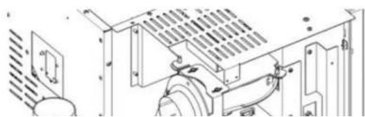
8.13. Fan direction only for PELLKAMIN 10+ EVO2
| Only qualified personnel can make the connections | |
| Perform each operation ONLY with the power supply disconnected | |
| Before moving the product, make sure that the tank is empty | |
To direct the fan, proceed as follows


3) Unscrew the screws

4) Remove the cover


EDILKAMIN

EDILKAMIN

9) Tighten the cap

10) Tighten the plate

11) Remove the pre-cut piece

12) Reassemble the support

EDILKAMIN
15) Move the gasket from the fan to the ducting pipe


EDILKAMIN
8.13.1. Possible adjustments
To connect the fan to the ducting pipe, proceed as follows:


INSTALLER
8.14. Plate assembly
For assembly, proceed as follows:
- Make sure that there is a power outlet on the back of the insert, so that it is accessible once installation is complete.
• After assessing the correct position of the insert

1) Open the door and lift the slide lock; attach the handle to the two pins

EDILKAMIN

3) Lift and pull outwards, so that the catch under the insert comes out of the slots on the plate


EDILKAMIN

5) Open the door and lower the slide lock


EDILKAMIN
- Secure the base plate to the base by means of the holes on the perimeter of the plate

Dimensions in cm


EDILKAMIN
- Fit the flue pipe (not supplied) on the smoke duct

- Fit the ∅ 40 mm pipe (not supplied) on the primary air duct. It can also be installed from under the base plate


EDILKAMIN


EDILKAMIN
8.15. Compensation vents

A : Ventilation grille inside the hood liner
B : Recirculation air inlet
C : External air intake

EDILKAMIN
8.16. Coatings, hood liners and their vents
Only coat the product after:
- Checking that the product is level.
- Connecting the product to the flue gas outlet and air intake
- Checking the product when hot
The installer must follow all the rules of proper installation and take all precautions against overheating and fire, in particular:
- When building a possible plinth under the base, a suitable gap must be provided for the passage of recirculation air from the room;
- The wooden parts must be protected with fireproof panels, not placed directly on them but at least 1 cm away from them, to allow an air flow which prevents heat from building up.
It is a good idea to ventilate the inside of the hood liner by exploiting the air flow that enters from below, which, by connective motion, will exit from the grille at the top, allowing for heat recovery and preventing excessive overheating; we recommend as on the previous page.
In addition to the above, take into account the regulations in force in each country concerning "insulation, finishes, coatings and safety recommendations".
| [WK$8] | Check the operation of the product before coating it.This check must be performed with the product switched on and running for a few hours, before installing the cladding, in order to be able to intervene if necessary.Consequently, finishing operations, such as the construction of the hood liner, the installation of the cladding, the execution of half pilasters, painting, etc., must be performed once the test has been successfully completed.Edilkamin shall not be held responsible for any costs deriving from demolition and reconstruction work, even if resulting from the replacement of any faulty parts of the insert. |

EDILKAMIN
9. FUEL: WOOD PELLETS
USER/INSTALLER
Use class A1 wood pellets in accordance with Standard UNI EN ISO 17225-2 or similar local regulations that provide for the following characteristics.
diameter 6 mm;
length 3-4 cm
moisture <10 %
| For the protection of the environment and for safety reasons, DO NOT burn, among other materials: plastic, painted wood, coal, bark waste.The use of other fuels may damage the product.DO NOT USE THE PRODUCT AS AN INCINERATOR. |
9.1. Pellet storage
Pellets are hygroscopic, i.e. they absorb moisture.
It is therefore necessary to store the pellets in a dry place, in their original bag, away from moisture.
Pellets should normally be at least 1.5 metres away from visible fires.
Large quantities of pellets must be stored in ventilated places, in accordance with local regulations.

EDILKAMIN
10. INSTRUCTIONS FOR USE
USER/INSTALLER
| The use of fuel other than the recommended pellets may cause damage to the product | |
| Be careful not to touch the smoke exhaust pipe if hot. | |
| ExpansionLike all products, it heats up and cools down during the various phases. This results in normal expansion.This expansion may result in slight noises which are not a cause for complaint. | |
| SmellsDuring the first start-ups, you may smell paint, but the smell will disappear in a short time.Start the product in a well-ventilated room the first times it is used. | |
| The product can be operated only after assembling the covers.Power up the product only after completing its assembly and the covers have been fitted.Otherwise there is a risk of accessible live parts. |
| The product can be operated only after assembling the covers.Power up the product only after completing its assembly and the covers have been fitted. Otherwise there is a risk of accessible live parts. |

EDILKAMIN
10.1. Training before use

The technician is responsible for teaching the customer how to use and perform maintenance on the product.
In particular, to use it in the best way possible, we suggest discussing the following topics with the technician:
- Operation
- Fuel
- Ignition
• What to do in the event of problems - Use suitable for installation conditions

Do not make changes to the installation conditions on your own initiative (including air intakes)
10.2. Steps for the first start-up
- Be sure to have read and understood the contents of this manual.
- Remove all flammable components from the product (manuals, labels, etc.). In particular, remove any labels from the glass.
• Make sure that the technician has performed the first start-up, filling the pellet hopper for the first time too.

EDILKAMIN
10.3. Loading pellets into the hopper
The pellets can be loaded in 3 different ways:
- Mouth border frame kit (EXTRACTION PELLETS LOADING RUNNERS; WHEN THE PRODUCT IS OFF)
- Front drawer loading kit
- Hatch loading kit with chute
10.3.1. Extraction on slide rails (PRODUCT IS OFF)
Make sure that the pellets do not spill out.
Should any leakage happen suction it when cold to prevent dust.


EDILKAMIN

2) Close the door and pull out the insert slightly


EDILKAMIN
11. INTERFACE AND OPERATING MODES
USER/INSTALLER
11.1. Operating modes
| Mode | Settable parameters |
| MANUAL | Power levelVentilation level (the fans, if there is more than one, can be adjusted separately)* |
| AUTOMATIC | Desired room temperatureVentilation level* (as in manual mode) |
| CHRONO | Desired room temperature, chosen on the different days of the week/PowerVentilation level* (as in manual mode) |
a by lowering ventilation, the product can also automatically modulate the power to maintain maximum performance and avoid overheating.
Where necessary, a safety function is provided: if for reasons of use or installation the set ventilation does not allow the necessary heat dissipation, ventilation is started automatically at maximum speed.
for INSERTS
If the safety function trips frequently, have the installation checked: particularly the presence of ventilation grilles.
| Function | Modes in which it can be activated | What it does |
| STAND-BY | AutomaticChrono prog. | when the temperature set-point is reached, the product switches off and then back on again when the |

11.2. Interface

The Mind

The Mind App
The product can be managed alternatively through
- BLUETOOTH REMOTE CONTROL: can be used for all features, near the product. The remote control display indicates the signal strength (see the dedicated chapter)

- The Mind APP: To download to your Smartphone, for all features with direct connection or when you are not at home with Internet connection and registration
• VOCAL COMMANDS with Edilkamin OPTIONAL ACCESSORIES: Alexa or Google Home - SAVE PANEL: IN CASE OF NEED, it is possible to manage certain functions. The SAVE PANEL is located on the product

EDILKAMIN
12. OPTIONAL PROBES/THERMOSTATS CONNECTIONS
USER/INSTALLER
On the product (accessible by removing the coating, with the electricity off and only by qualified technicians) a dedicated low voltage terminal block can be found
The installer assesses them according to the type of system.
There are two possible modes of operation.
The installer can help you choose, according to your needs:
| Thermostat on home automation contact | Thermostat in place of the ambient probe of the radio control | |
| ACTION | The product turns on/off without any modulation. | The product modulates, goes into stand-by and turns on/off |

After installation and commissioning, we recommend reviewing all daily operations and useful documents with the technician. In particular: use of the display, pellet loading, maintenance, what to do in case of problems.
On the product (accessible from the right-hand side by removing the protective panel, with the electrical power supply disconnected and only by authorised technicians) a dedicated low voltage terminal block can be found, to connect probes and thermostats.


EDILKAMIN
INSTALLER
- -Pin 5-6 = room input zone 1 = thermostat as an alternative to the radio control probe
- -Pin 3-4 = room input zone 2 = probe or thermostat of the relative zone for products with ducting
- -Pin 1-2 = home automation input = commercial telephone dialler or remote On-Off or thermostat


The connections must be made by qualified personnel, in accordance with local and national regulations, with the product disconnected from the power supply.

In case of connection of probes or thermostats on the room inputs, the relevant parameters must be set in the Technical Menu of the appliance.
12.1. Remote control

EDILKAMIN
12.1.1. Remote control energy saving
After a period of inactivity, the backlighting dims and the display turns off.
If any key is pressed with the display off, the display and the backlight will turn on again. This only refers to the remote control, not the product itself.

The life of the remote control batteries depends on use.
Edilkamin and the reseller will not consider claims for battery life under any circumstances.

Remote control

Wall mount
| Key | Use | Use in the menus |
 | Switch from OFF to ON and vice versa | / |
 | Increase settable values | Scroll through items |
 | Decrease settable values | Scroll through items |

EDILKAMIN
| Activate or deactivate the CRONO function | / | |
| AUTOMATIC or MANUAL mode | / |
| Symbol | Meaning |
| Remote control Bluetooth communication. Signal strength | |
| Only on if the battery is running low | |
| Maintenance necessary symbol.Appears after a certain number of hours of operation. In any case, contact the TAC. | |
| The relative function is active (Relax - airKare - EasyTimer - Crono).EasyTimer and Crono cannot be activated simultaneously. | |
| Reserve indicator. It switches on if the function is active. The arrows switch on in sequence to signal that the tank must be filled. | |
| Presence of flame and stove power. | |
| Switch on | |
| Power level 1 | |
| Power level 2 |

EDILKAMIN
| SET | Setting. Indicates that the remote control is in the setting mode. The settable value will appear in the bottom bar. |
| SET22.5 | Digits for SET-POINTS. Setting of the various SET-POINTS: temperature, power, fan speed. |
 | Bottom bar for “Weekly Hour Schedule” and “Messages |
MON TUE WED THU FRI SAT SUN | Days of the week and time bar. They only appear if the timer (Crono) has been activated. |
| Chimney sweep function active |
12.2. First power supply
When switching on for the first time, if the language has not been set, the "Language, Date, etc." menus will appear (explained in the dedicated chapter)
12.3. Possible states of the product
- OFF: the product is "deactivated" and does not generate heat.
- ON: the product is "active" and able to meet the heat request.
- ALARM: see the paragraph "Advices for eventual inconveniences".
- ON/OFF WITH STAND-BY ACTIVE: If the product was working, it switches to minimum power and waits for the set time before switching off. If the product was being switched on, it completes the start-up phase, switches to

EDILKAMIN
12.4. Switch on screen

Ignition takes a few minutes, during which the flame should appear. Simply wait without taking any action
During ignition, the display shows the status (CLEANING; IGNITION; etc.)


EDILKAMIN
12.5. AUTOMATIC and MANUAL setting

In AUTOMATIC mode:
Room temperature setting (measured by the remote control, which should be kept in the room where the product is installed). Change the temperature set-point using the "+" and "-" buttons.
![graph TD A["10:00 SET 20.0 AUTO"] --> B["+"] B --> C["X 1"] C --> D["14,9° SET 20.5 AUTO"] D --> E["X 1"] E --> F["14,9° SET 20.5 AUTO"]](/content/2026/07/1506886/images/e80f03860209bf3a71002210301c35c8855bddd9ae9e830c6e636de0b951e4f4.jpg)


The setting can be confirmed with the button or by waiting 5" without pressing any button. After confirming, SET will stop flashing.
In MANUAL mode:
Power setting. Change the power level using the "+" and "-" buttons.

EDILKAMIN
12.6. Ventilation
![graph TD A["14,9° SET 20.0"] --> B["X1"] B --> C["10:00 SET F1"] C --> D["X2"] D --> E["10:00 SET F1"] E --> F["X1"] F --> G["10:00 SET F1"] G --> H["Max"] H --> I["Auto"]](/content/2026/07/1506886/images/5e08c3f06e418009efe286f0fcb45d4f083d3f18db9bdc272798e98e4a14e820.jpg)

EDILKAMIN
12.6.1. With optional room probe (for products with ducting)
DUCTED ZONES 2 AND 3 ROOM SET-POINT
The setting can only be made with ducted-air stoves.
If two or more optional room probes are connected and activated, it is possible to set the relative room set-point and display the room temperature.

After setting the installation room temperature (or with the room power in manual mode), if you wait 5" without pressing any buttons, "SET" will stop flashing and you will exit the settings page.
Otherwise, if you confirm by pressing the button, you can set the room set-point for zone 2 (if the probe is present and active) indicated in the bottom bar.


EDILKAMIN
12.7. RELAX function

Function not present on this model
12.8. EASY TIMER function (delayed switch on and switch off)
This function switches the product on/off after a set period from activation of the function.
Useful if, for example, you go to sleep and want to switch off/switch on the product after a few hours.
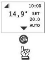
By activating the Easy Timer function with the product on, the switch-off time can be set with 1/2 hour intervals.
By activating the Easy Timer function with the product off, the user sets the switch-on time.
Example: Switch-ON in 1/2 hours' time.


EDILKAMIN
The Easy Timer function can be deactivated by pressing the dedicated button.
The display will show an arrow above the button and the countdown.

To vary the timer before the switching on or off, it must be deactivated and then reset.
12.9. CHRONO
After having set times, temperatures or powers in the CHRONO prog. MENU, if the product is in automatic mode, chrono prog. works with the room temperature, otherwise it works with power.
Pressing the button allows you to switch from temperature chrono to power chrono and vice versa.
Briefly pressing the button activates or deactivates the Chrono prog. (programmed in advance via APP or remote control).

The timer is programmed from the MENU. The CHRONO button is only used to activate/deactivate the function.
12.10. Menu
The items of the user menu are the following. The others are only for the technician or to be read under his/her guidance.
Next to the temperature, the progressive number of the Menu item (not sequential) is displayed, called "Set digit."
Below is the Menu item.
Example "(02 = digit; STAND BY)

EDILKAMIN
12.10.1. How to access the menus

: To enter the Menus

To go from one Menu to another

: To enter the Menu
![graph TD A["Station 1: 14,9° SET 20.0"] --> B["Station 2: 14,9° 02 STAND-BY"] B --> C["Station 3: 10:00 SET"] C --> D["Station 4: 10:00"] D --> E["Station 5: X1"] E --> F["Station 6: X1"] F --> G["Station 7: X1"] G --> H["Station 8: X1"] H --> I["Station 9: X1"] I --> J["Station 10: X1"] J --> K["St…](/content/2026/07/1506886/images/5582654157db707b59daafabd8b042600b9de95d6a04320e53c0e60a631983cd.jpg)

EDILKAMIN
12.10.2. Stand-By
When the Stand-by function is active, when the temperature set-point is reached, the product switches off and switches on again when the room temperature drops below the desired temperature.
When the Stand-by function is not active, the product sets itself to minimum power when the temperature set-point is reached.
The product is programmed by default with a delta of 1 °C to ensure best comfort.
The technician may vary this setting during the first ignition to meet specific requirements.
12.10.3. Access to the Menu and setting
![graph TD A["SET 10:00 20.0"] --> B["STAND-BY 10:00 02"] B --> C["X1"] D["SET 14.9°"] --> E["STAND-BY 14.9°"] E --> F["X1"] G["SET 14.9°"] --> H["STAND-BY 14.9°"] H --> I["X1"] J["SET 14.9°"] --> K["STAND-BY 14.9°"] K --> L["X1"] M["SET 14.9°"] --> N["STAND-BY 14.9°"] N --> O["X1"] P["SET 14.9°"] -->…](/content/2026/07/1506886/images/9fbffd505e9d2ffe6290f3bc3d2d9225549e78a39dfe32079842f58e4ec3a333.jpg)

EDILKAMIN
| Available in AUTO mode onlySTAND-BYFunction not activeSTAND-BYFunction active but product OFFSTAND-BYFunction active and product ONProduct shutting down due to STAND-BYProduct off due to STAND-BY |
| THE ROOM TEMPERATURE PROBE IS ON THE REMOTE CONTROLThe reading depends on where the remote control is; if it loses connection, the reading is made by a probe placed inside theproduct (except for inserts). The reading may be different.According to the needs, the temperature reading can be adjusted via the SET TEMPERATURE menu. |

EDILKAMIN
Allows for loading the pellets once the screw feeder has emptied completely. Useful for the technician during the initial start-up.
Available only in the OFF status. Any attempt to activate the function in other statuses will not be allowed.
![graph TD A["14,9° SET 20.0"] --> B["MENU"] B --> C["X1"] D["14,9° ON 02"] --> E["STAND-BY"] E --> F["X1"] G["14,9° ON 03"] --> H["OK"] H --> I["X1"] J["14,9° ON OFF"] --> K["CARICO PELLET"] K --> L["X1"] style A fill:#f9f,stroke:#333 style D fill:#f9f,stroke:#333 style G fill:#f9f,stroke:#333 style…](/content/2026/07/1506886/images/53c7fee8552a1e5ac0b82972fd8e8d7f7516ee84b5ffc8aeb3dbf277b43d402a.jpg)

EDILKAMIN
12.10.5. Chrono prog.
To set the Chrono prog. function.
![graph TD A["14,9° SET 20.0"] --> B["X1"] B --> C["14,9" 04 CRONO"] C --> D["X2"] D --> E["LUN"] E --> F["X1"] F --> G["10:00"] G --> H["MAR"] H --> I["X1"] I --> J["10:00"] J --> K["X1"] K --> L["00:00"] L --> M["X1"] M --> N["00:30"] N --> O["X2"] O --> P["00:30"] P --> Q["X1"] Q --> R["09:00"…](/content/2026/07/1506886/images/b08f3c1bef8481651ac0a60dc1d52239a1d58700c3b8a14ddfa9b19b34019f02.jpg)

EDILKAMIN
12.10.6. Chrono temp. (T1-T2)
To set the target temperatures of the Chrono prog.
![graph TD A["14,9° SET 20.0"] --> B["14,9° 05 TEMP.CRONO"] B --> C["14,9° 05 Temp.CRONO T1=20.0°C"] C --> D["14,9° 05 TEMP.CRONO T1=22.0°C"] D --> E["14,9° 05 Temp.CRONO T2=25.0°C"] E --> F["14,9° 05 Temp.CRONO T3=25.0°C"] F --> G["14,9° 05 Temp.CRONO T1=20.0°C"] G --> H["14,9° 05 Temp.CRONO T1=22.0°…](/content/2026/07/1506886/images/65d6a96a234fd1fae8ea6cb01159c1cf8970929622e5c50f3e5c30c37c7a64e5.jpg)

EDILKAMIN
12.10.7. Date and time
Can be used to set the current date and time
![graph TD A["14,9° SET 20.0"] --> B["DATA-ORA"] B --> C["X1"] C --> D["ORA LEGALE AUTO OFF"] D --> E["X1"] E --> F["SINCRO WEB ON"] F --> G["X1"] G --> H["DATA-ORA 24 ORE"] H --> I["X1"] I --> J["14,9° 06"] J --> K["SINCRO WEB OFF"] K --> L["X1"] L --> M["14,9° 06"] M --> N["SINCRO WEB ON"] N --> O["…](/content/2026/07/1506886/images/207198ef801477179856b460be1ba8ad913f9e61a811a6839e1ef6aedc9b0737.jpg)

EDILKAMIN
12.10.8. Language
Can be used to select the language
![graph TD A["14,9° SET 20.0"] --> B["MENU X 1"] B --> C["14,9° LINGUA 07"] C --> D["OK X 1"] D --> E["14,9° 07"] E --> F["14,9° 10:00"] F --> G["14,9° 07"] G --> H["+ X 3"] H --> I["14,9° 07"] I --> J["OK X 1"] J --> K["14,9° 10:00"] K --> L["14,9° 07"]](/content/2026/07/1506886/images/742c9e4c0cdcccafe11e6aa381357a7f975c18bce5ba229afdefd5d75c6d02a2.jpg)

EDILKAMIN
12.10.9. Display
Allows for choosing the level of brightness of the display.
![graph TD A["14.9° SET 20.0"] --> B["14.9° ON LUMINOSITÀ ON"] B --> C["14.9° ON LUMINOSITÀ ON 70%"] C --> D["14.9° ON LUMINOSITÀ ON 80%"] D --> E["14.9° ON LUMINOSITÀ STBY 20%"] E --> F["14.9° ON LUMINOSITÀ STBY 10%"] F --> G["14.9° ON LUMINOSITÀ ON 80%"] G --> H["14.9° ON LUMINOSITÀ ON 60%"] H --> I…](/content/2026/07/1506886/images/8299eeb0ac53115b2e26a5ddd3a222267297d5f9b118f3ff95ebc83457bb22d8.jpg)

EDILKAMIN
12.10.10. Info
These readings should only be done when requested by the technician.
The technician understands the diagnostic meaning of the messages and values, and may ask you to read them to him/her if you experience problems.
![graph TD A["14,9° SET 20.0"] --> B["14,9° 09 INFO"] B --> C["14,9° 09 ESTRATTORE 2000(2800)RPM"] C --> D["14,9° 09 MOTORIDUTTORE 2000(2800)RPM"] D --> E["14,9° 09 TEMPERATURA FUMI 100°C"] E --> F["14,9° 09 X1"] F --> G["14,9° 09 X7"] G --> H["14,9° 09 X1"] H --> I["14,9° 09 SET 20.0"] I --> J["14,9°…](/content/2026/07/1506886/images/3da4261c67af8983e6eb8cc980ca40e58a1258db9fbbdd95d385506f3e379b99.jpg)

EDILKAMIN
Below is a description of the items
- Temperature of fumes: Indicates the temperature value read inside the product. To be read only with the guidance of the Technical Assistance Centre.
- Auger motor: Indicates the set and read speed. Useful to understand any anomalies of the pellet loading motor. To be read only with the guidance of the Technical Assistance Centre.
- Extractor: Indicates the set and read speed. Useful to understand any anomalies of the combustion chamber vacuum motor. To be read only with the guidance of the Technical Assistance Centre.
- Leonardo: Indicates the set and read target value. To be read only with the guidance of the Technical Assistance Centre.
• Fan: Indicates the output voltage. To be read only with the guidance of the Technical Assistance Centre. - Ignition plug (glow plug): Indicates whether the ignition component is on or off. Useful during ignition to understand functionality.
• Home automation contact: Indicates whether ON or OFF. Useful to understand functionality.

EDILKAMIN
12.10.11. Software
These readings should only be done when requested by the technician.
![graph TD A["MENU X 1"] --> B["SOFTWARE"] B --> C["OK X 1"] D["SCHED BASE 4.0.230220"] --> E["OK X 1"] F["14,9° 10:00 SET 20.0"] --> G["14,9° 10:00"] H["14,9° 10:00"] --> I["14,9° 10:00"] J["14,9° 10:00"] --> K["14,9° 10:00"] L["14,9° 10:00"] --> M["14,9° 10:00"]](/content/2026/07/1506886/images/20915e9295c6e09cf1f1e54162d29f4da9edab4cd5bf2e1a5a46fdd9f2ba0a02.jpg)

EDILKAMIN
12.10.12. Data
Allows for the product counters to be displayed.
These readings should only be done when requested by the technician.
![graph TD A["14,9° SET 20.0"] --> B["SET X1"] B --> C["14,9° 11 DATI"] C --> D["14,9° 11 DATI N°ACC.=30"] D --> E["14,9° 11 DATI ORE LAVORO=300"] E --> F["14,9° 11 DATI ORE P1=50"] F --> G["14,9° 11 DATI N°ACC.=30"] G --> H["14,9° 11 DATI N°ACC.=30"] H --> I["14,9° 11 DATI N°ACC.=30"] I --> J["14,9°…](/content/2026/07/1506886/images/5bb2a34f4c9cc8100571bd048a572e59315e7d43e9b5b98eac91af418babf902.jpg)

EDILKAMIN
12.10.13. Alarms
These readings should only be done when requested by the technician.
The alarms are arranged from the most recent to the oldest.
12.10.14. Pellet drop
To set the auger motor in continuous cycle or step operation. To be carried out only under the guidance of a technician.
![graph TD A["14,9° SET 20.0"] --> B["MENU X1"] B --> C["14,9° CADUTA PELLET"] C --> D["X11"] D --> E["14.9° 13"] E --> F["10:00"] F --> G["10:00"] G --> H["10:00"] H --> I["14.9° 13"] I --> J["10:00"] J --> K["10:00"] K --> L["14.9° 13"] L --> M["10:00"] M --> N["10:00"]](/content/2026/07/1506886/images/78c500c90b85d0a8d24920c509af4a7b0c78a11b786d1b0c49b06db1a478fb6e.jpg)

EDILKAMIN
12.10.15. Pellet sensor (if present)
Allows to set the pellet level sensor ON or OFF.
![graph TD A["14,9° SET 20.0"] --> B["MENU X 1"] B --> C["SENSORE PELLET"] C --> D["X 12"] D --> E["OK X 1"] E --> F["SENSORE PELLET OFF"] F --> G["X 1"] G --> H["14,9° 14"] H --> I["10:00 SET"] I --> J["10:00 SET"] J --> K["10:00 SET"] K --> L["10:00 SET"] L --> M["10:00 SET"] M --> N["10:00 SET"] N…](/content/2026/07/1506886/images/114d1b0e08e80f30d7ce3a66fed5402ec79b8d749d7ca41234c250c3e07bb325.jpg)

EDILKAMIN
12.10.16. Temperature set
In order of scrolling, it can be found after the technical menu.
- ADJ T. AMB1: Plus or minus variation of the value read by the temperature probe on the product
- ADJ TEMP.AMB RC: Plus or minus variation of the value read by the temperature probe on the remote control

The function is useful for adapting to the temperature requirements in the house
![graph TD A["14,9° SET 20.0"] --> B["SET TEMPERATURA"] B --> C["ADJ T.AMB1 +0.0°C (18,7°C)"] C --> D["ADJ T.AMB1 +1.0°C (18,7°C)"] D --> E["14,9° 16"] E --> F["ADJ T.AMB1"] F --> G["14,9° 16"] G --> H["14,9° 16"] H --> I["14,9° 16"] I --> J["14,9° 16"] J --> K["14,9° 16"] K --> L["14,9° 16"] L --> M[…](/content/2026/07/1506886/images/3b035164e89e776f4debaab6d21ddeff9b2ecdeb73ac1690192b86c94d150ff0.jpg)

EDILKAMIN
12.11. Technical menu
INSTALLER
The various sub-menus are the following:
- Flame type
- Pellet type
- Min chimney sweep (the function can be activated only with the product on)
- Nom chimney sweep (the function can be activated only with the product on)
- Parameters
12.12. Access to the Menu and setting
Only accessible by a technician with the correct password (1111)
![graph TD A["14,9* SET 20.0"] --> B["10:00"] B --> C["14,9* 15 MENU TECHNECO"] C --> D["10:00"] D --> E["14,9* 15 PASSWORD 000"] E --> F["10:00"] F --> G["14,9* 15 PASSWORD 1.00"] G --> H["10:00"] H --> I["14,9* 15 PASSWORD 000"] I --> J["10:00"] J --> K["14,9* 15 MENU TECHNECO"] K --> L["10:00"] L -…](/content/2026/07/1506886/images/df0f9f7a9577e32dacdaee0928b51e9a74d88ba0230290dbfd7e1145955262a0.jpg)

EDILKAMIN
12.12.1. Flame type
In correct installation conditions, with the Service Centre parameters appropriately adjusted, with high-quality pellets, the flame intensity is adjusted:
- Standard
- Eco
- Plus
![graph TD A["10:00"] --> B["14,9° 15"] B --> C["PASSWORD 1111"] D["10:00"] --> E["14,9° 15"] E --> F["TIPO FIAMMA"] G["14,9° 15"] --> H["TIPO FIAMMA STANDARD"] I["OK"] --> J["X 1"] K["OK"] --> L["X 1"]](/content/2026/07/1506886/images/2bd017d92ce8ab252242a856feb113502f3a396e49da1ec4c31a8449c63f798d.jpg)

EDILKAMIN
12.12.2. Pellet type
In correct installation conditions, with the Service Centre parameters appropriately adjusted, with high-quality pellets, pellet loading is adjusted:
- Medium
- High
- Low
![graph TD A["14,9° 15<br>PASSWORD 1111"] -->|OK X1| B["14,9° 15<br>TIPO FIAMMA"] B -->|X1| C["14,9° 15<br>TIPO PELLET"] C --> D["14,9° 15<br>TIPO PELLET MEDIUM"] D -->|OK X1| E["14,9° 15<br>TIPO PELLET MEDIUM"] E --> F["14,9° 15<br>TIPO PELLET MEDIUM"] F --> G["14,9° 15<br>TIPO PELLET MEDIUM"] G -->…](/content/2026/07/1506886/images/1f39e196999dad094839134a55b3ea44ba2c6029ed973cc51a18d310b1136784.jpg)

EDILKAMIN
12.12.3. Chimney Sweep
The various functions are the following:
- Min chimney sweep
- Nom chimney sweep
The product operates at maximum power or minimum power for 15 minutes, with fixed smoke extractor and auger motor revolutions


EDILKAMIN
12.12.4. Parameters
INSTALLER
- Pellet level sensor: Enables or disables the possibility for the end customer to view and choose the status of the pellet reserve indicator
- Airkare function: To select WHETHER Airkare is active and how big the room is (SMALL, less than 30 m 3 or BIG) or not active (OFF)
- Reset Airkare: Allows to reset the working hours of Airkare
- Number of fans: Enables or disables the possibility for the end customer to operate the fan, if present. Do not change unless in the presence of the Technical Assistance Centre
- Ducting 2: Enables the speed of the ducting fan to be set to maximum (ON-OFF)
- Ducting 3: Enables the speed of the ducting fan to be set to maximum (ON-OFF)
-
Room input: To choose which item can be read and adjusted by the customer on the Home display. It depends on the type of system
-
Probe: Room probe, standard in the product
- Thermostat: Enables the thermostat, which can be installed instead of the room probe.
- Room2/Cyli. input: To choose which item can be read and adjusted by the customer on the Home display. It depends on the type of system
- No input (default)
- Probe
- Thermostat
• Room/Cyl/se: Defines the item to be enabled according to the connected component
- No input (default)
- Probe
- Thermostat
• Chrono synch: Synchronises the chrono prog.
When active (ON), the set operating times apply in both automatic and manual mode
- Unpair bluetooth: Do not confirm with OK, the remote control is disconnected
- Extra tank: Not available for this model
•

EDILKAMIN
13. USER INSTRUCTIONS: SAVE PANEL
USER/INSTALLER


EDILKAMIN
To switch off with the product on: Press the On-Off button for a few seconds
To unlock the product in the event of a blocking alarm: Press the On-Off button for a few seconds
The table below explains the conditions in which the LED lights will come on:

| LED 1 | Voltage present |
| OFF | Absent |
| ON | Present |

| LED 2 | EK Cloud connection |
| OFF | Absent |

14. MAINTENANCE
USER/INSTALLER
Before performing any maintenance operation, disconnect the product from the mains power supply.
A lack of maintenance prevents the product from operating smoothly.
Any problems due to a lack of maintenance will invalidate the warranty.

The characters of the safety information are larger according to the standards
14.1. Daily maintenance
Operations to be performed, with the product switched off, cold and preferably disconnected from the mains. A suitable vacuum cleaner is required.
The entire procedure takes a few minutes.


3) Remove the protection grille

4) Remove the contents of the ash drawers
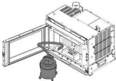
5) Vacuum the inside of the firebox and the compartment where the ash falls

EDILKAMIN

EDILKAMIN
14.1.1. Cleaning the glass
Clean the glass only when it is cold. Use a dry brush and, if necessary, a specific detergent: spray a little detergent on the glass and clean with a cloth. There are specific products that can be used to clean the glass (see our Glasskamin price list).
Make sure that there are no abrasive elements in the ash that could damage the glass.

Do not spray the cleaning product onto the painted parts or on the door gaskets.


EDILKAMIN
14.2. Periodic maintenance
USER/INSTALLER
The frequency of periodic maintenance depends on use, in agreement with the technician.


EDILKAMIN

2) Disassemble the front part with snap in fixing


EDILKAMIN

4) Vacuum the compartments

If not performed correctly, the operation of the product may be compromised

The drawings are only indicative but not always refer to a specific model

EDILKAMIN
14.3. Seasonal maintenance
USER/INSTALLER

Seasonal maintenance is performed by the technical service centre, in accordance with local and national regulations. The technician can find instructions on the website.
It consists of general internal and external cleaning.
Remember that seasonal maintenance by a qualified technician, and according to national and local regulations, is necessary.

In the case of very frequent use of the product, it is advisable to clean the smoke flue and duct every 3 months.
In any case, clean the chimney system at least once a year (check whether there are regulations in your country).
Periodically empty any TEE placed on the chimney system by the installer

We recommend that you DO NOT use compressed air to clean the combustion air inlet pipe

If regular inspections and cleaning are not carried out, there will be an increased risk of fire in the chimney.
14.4. Repairs

EDILKAMIN
15. DISPOSAL
At the end of its service life, dispose of the product in accordance with current regulations.
15.1. Warnings for the correct disposal of the product
The demolition and disposal of the product are the sole responsibility of the owner who will have to act in compliance with the applicable laws in their country on safety, respect and protection of the environment.

Do not dispose of with municipal waste.
Do not throw it away.
15.2. Disposal of the components of the appliance at the end of its service life

The drawings are indicative

EDILKAMIN
| • Ceramic glass (fire door): dispose of in inert or mixed waste• Tempered glass (oven door): dispose of in glass | • Wiring, motors, fans, pumps, display, sensors, spark plug, electronic boards.Dispose of separately at authorised centres, as indicated by the WEEE directive 2012/19/EU |
| E. METAL STRUCTUREDispose of separately in metal | G. HYDRAULIC COMPONENTSPipes, fittings, expansion tank, valves.If present, dispose of separately according to the material they are made of:• Copper • Brass • Steel • Other materials |
| F. NON-RECYCLABLE COMPONENTS.• Gaskets• Rubber hoses• Silicone or fibreDispose of in mixed waste |
15.3. WEEE
Pursuant to art. 26 of Italian Legislative Decree of 14 March 2014, no. 49 "Implementation of Directive 2012/19/EU on waste electrical and electronic equipment (WEEE)".
The crossed bin symbol on the appliance or on its packaging indicates that the product at the end of its useful life must be collected separately from other waste.
The user must therefore deliver the equipment at the end of its life to suitable recycling centres for electronic and electro-technical waste.
Adequate separate collection for subsequent recycling, treatment and environmentally compatible disposal contributes to avoiding possible negative effects on the environment and on health and encourages reuse and/or recycling of the materials of which it is composed.


EDILKAMIN
16. ADVICE FOR POSSIBLE PROBLEMS
In the event of problems, the product automatically performs the shutdown operation.
The display shows the reason (see below).
16.1. Display messages

| MESSAGE | PROBLEM | ACTIONS |
| A01 | It is shown if the combustion air intake flow rate falls below a preset level | Make sure that the firebox door is closedMake sure that maintenance is carried out regularly on the productMake sure that the smoke outlet and combustion air intake duct are clean |
| A02 | It is shown if the motherboard does not detect the correct smoke fan speed | Contact the technician |
| A03 | It is shown if the thermocouple detects a smoke temperature lower than a set value, interpreting this as absence of flame | Check the absence of pallets in the tankContact the technician |
| A04 | It is shown if ignition is not successful within the set time | The two cases below must be considered: |

EDILKAMIN
| A07 | Switch-off due to high smoke temperature | Check the pellet type (in case of doubt contact the technician)Contact the technician |
| A08 | Switch-off due to excessive temperature in the product or, for the “CHERIE EVO AT/ATC” stove, pellet hopper door open | Check that the product is cleanFor the “CHERIE EVO AT/ATC” stove check that the pellet hopper loading door is closedContact the technician |
| A09 | Shutdown due to pellet loading problem (auger motor).For airtight products (except for the “CHERIE EVO AT/ATC” stove), pellet hopper door open | For airtight products (except for the “CHERIE EVO AT/ATC” stove), check that the pellet hopper loading door is closedIn the PELLET LOAD sub-menu, select STEPContact the technician |
| A10 | Switch-off due to electronic motherboard overheating. | Contact the technician |
| A11 | Switch-off due to tripping of the safety pressure switch.For airtight products, open door indication | Check the cleaning of the product, of the dischargeCheck that the door is closed properlyContact the technician |
| A12 | Room temperature probe faulty. | Contact the technician |
| A13 | Fault in ducting room temperature probe 2 (if present). | Contact the technician |
| A14 | Fault in ducting room temperature probe 3 (if present). | Contact the technician |
| A20 | Triggers when the electronic board detects movement of the pellet loading auger motor | Contact the technician |

EDILKAMIN
16.2. Remote control battery level low
If the battery level is low, the battery symbol appears on the remote control display

16.3. Maintenance (message that does not cause switch-off)

After 1500 hours of operation, a "wrench" symbol appears on the display
The product works, but maintenance must be carried out by the Edilkamin qualified technician

EDILKAMIN
16.4. No communication
In the event of a prolonged absence of communication between the product and the remote control, the signal icon shows the minimum value

16.5. Pellet reserve light (where the sensor is present)
The function is available only if the pellet level sensor is installed and activated.
When the level sensor is triggered, the board emits a single "beep" (in any state of ignition or operation) and the moving reserve symbol appears


EDILKAMIN
- with the product OFF or in Initial Cleaning mode (following manual emptying of the tank), the final symbol will immediately appear and the stove cannot be switched on;
- during the ignition phase, the ignition sequence will be completed even if it lasts more than the 20/30 minutes of residual autonomy.
If the pellets are not reloaded, the stove will then switch off.
16.6. Black-out


During a switch-off following a BLACK-OUT, the display will alternately show the words "Black-Out" and "OFF". Once the switch-off has been completed, the product will remain off and "Black-Out" will appear.

EDILKAMIN

EDILKAMIN

EDILKAMIN
iosonoilfuoco
www.edilkamin.com
- EDILKAMIN
- INSTRUCTIONS FOR USE
- INTERFACE AND OPERATING MODES
- OPTIONAL PROBES/THERMOSTATS CONNECTIONS
- NOTE ON EDITION AND LANGUAGE
- NOTE ON THE LANGUAGE OF THE MANUAL
- DIGITAL ONLINE EDITION
- CE MARKING INFORMATION
- INTRODUCTION
- RECIPIENTS OF THE MANUAL
- GENERAL NOTES
- MEANING OF THE SYMBOLS
- PRODUCT IDENTIFICATION AND WARRANTY
- CE PLATE: DATA AND POSITION
- SAFETY INFORMATION
- GENERAL NOTES FOR THE SAFE USE OF THE PRODUCT
- RECOMMENDATIONS AND PROHIBITIONS FOR THE SAFE USE OF THE PRODUCT
- POSSIBLE RISKS IF THE INSTALLATION, OPERATION AND MAINTENANCE INSTRUCTIONS ARE NOT FOLLOWED
- DIMENSIONS
- PELLKAMIN 10+ EVO
- PELLET LOADING DRAWER
- SUPPORT FRAME
- TECHNICAL DATA
- TECHNICAL DATA ACCORDING TO THE PRODUCT STANDARD
- ECODESIGN TECHNICAL DATA PELLKAMIN 8 EVO
- ECODESIGN TECHNICAL DATA PELLKAMIN 10+ EVO
- ECODESIGN REQUIREMENTS FOR SOLID FUEL LOCAL SPACE HEATERS ACCORDING TO COMMISSION REGULATION (EU) 2015/1185 AND ENERGY LABELLING OF LOCAL SPACE HEATERS ACCORDING TO COMMISSION REGULATION (EU)
- UNPACKING
- NOTES ON UNPACKING
- PACKAGING DISPOSAL INSTRUCTIONS
- REMOVE FROM THE PALLET
- LOCKING PLATE
- INSTALLATION
- PRELIMINARY REMARKS ON INSTALLATION
- CHIMNEY SYSTEM (SMOKE DUCT, CHIMNEY FLUE AND CHIMNEY POT)
- SMOKE DUCT
- THE CHIMNEY FLUE
- DUCTED SYSTEM
- THE CHIMNEY POT
- ELECTRICAL CONNECTION
- FAN DIRECTION ONLY FOR PELLKAMIN 10+ EVO
- POSSIBLE ADJUSTMENTS
- PLATE ASSEMBLY
- COMPENSATION VENTS
- COATINGS, HOOD LINERS AND THEIR VENTS
- FUEL: WOOD PELLETS
- USER/INSTALLER
- PELLET STORAGE
- TRAINING BEFORE USE
- STEPS FOR THE FIRST START-UP
- LOADING PELLETS INTO THE HOPPER
- EXTRACTION ON SLIDE RAILS (PRODUCT IS OFF)
- FOR INSERTS
- INTERFACE
- INSTALLER
- REMOTE CONTROL
- REMOTE CONTROL ENERGY SAVING
- FIRST POWER SUPPLY
- POSSIBLE STATES OF THE PRODUCT
- SWITCH ON SCREEN
- AUTOMATIC AND MANUAL SETTING
- WITH OPTIONAL ROOM PROBE (FOR PRODUCTS WITH DUCTING)
- DUCTED ZONES 2 AND 3 ROOM SET-POINT
- RELAX FUNCTION
- EASY TIMER FUNCTION (DELAYED SWITCH ON AND SWITCH OFF)
- CHRONO
- MENU
- HOW TO ACCESS THE MENUS
- STAND-BY
- ACCESS TO THE MENU AND SETTING
- CHRONO PROG
- CHRONO TEMP. (T1-T2)
- DATE AND TIME
- LANGUAGE
- DISPLAY
- INFO
- SOFTWARE
- DATA
- ALARMS
- PELLET DROP
- PELLET SENSOR (IF PRESENT)
- TEMPERATURE SET
- TECHNICAL MENU
- FLAME TYPE
- PELLET TYPE
- CHIMNEY SWEEP
- PARAMETERS
- USER INSTRUCTIONS: SAVE PANEL
- MAINTENANCE
- DAILY MAINTENANCE
- CLEANING THE GLASS
- PERIODIC MAINTENANCE
- SEASONAL MAINTENANCE
- REPAIRS
- DISPOSAL
- WARNINGS FOR THE CORRECT DISPOSAL OF THE PRODUCT
- DISPOSAL OF THE COMPONENTS OF THE APPLIANCE AT THE END OF ITS SERVICE LIFE
- WEEE
- ADVICE FOR POSSIBLE PROBLEMS
- DISPLAY MESSAGES
- REMOTE CONTROL BATTERY LEVEL LOW
- MAINTENANCE (MESSAGE THAT DOES NOT CAUSE SWITCH-OFF)
- NO COMMUNICATION
- PELLET RESERVE LIGHT (WHERE THE SENSOR IS PRESENT)
- BLACK-OUT
- IOSONOILFUOCO
Brand : EDILKAMIN
Model : PELLKAMIN 8 EVO2
Category : Fireplace