
Professional 3.0 system - Cooker BORA - Free user manual and instructions
Find the device manual for free Professional 3.0 system BORA in PDF.
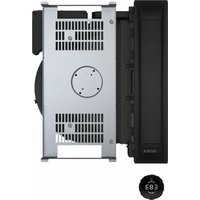


| Type of Product | Built-in induction hob with integrated extraction |
| Product Dimensions (W x D x H) | 900 x 520 x 52 mm |
| Cutout Dimensions (W x D) | 860 x 490 mm |
| Weight | Approx. 32 kg |
| Power Supply | 230 V / 50-60 Hz, 3-phase |
| Total Power | 7.4 kW |
| Number of Cooking Zones | 4 induction zones |
| Cooking Zone Sizes | 2x 18 cm, 1x 21 cm, 1x 28 cm (flex zone) |
| Boost Function | Yes, up to 3.7 kW per zone |
| Integrated Ventilation | Yes, with automatic air extraction |
| Ventilation Performance | Up to 620 m³/h |
| Control Type | Touch control with TFT display |
| Timer | Yes, with automatic shut-off |
| Child Lock | Yes |
| Residual Heat Indicator | Yes, per zone |
| Automatic Safety Shut-off | Yes |
| Cleaning | Glass ceramic surface, wiping with damp cloth |
| Grease Filter Type | Reusable metal grease filter (dishwasher safe) |
| Spare Parts Availability | Available through service centers |
| Repairability Index | 7.5 / 10 |
| Energy Efficiency Class | A+ |
| Noise Level (Ventilation) | 45 - 65 dB(A) |
| Color | Black |
Frequently Asked Questions - Professional 3.0 system BORA
User questions about Professional 3.0 system BORA
0 question about this device. Answer the ones you know or ask your own.
Ask a new question about this device
Download the instructions for your Cooker in PDF format for free! Find your manual Professional 3.0 system - BORA and take your electronic device back in hand. On this page are published all the documents necessary for the use of your device. Professional 3.0 system by BORA.
USER MANUAL Professional 3.0 system BORA
EN Installation instructions Professional 3.0
Contents
1 General information 3
1.1 Validity of the operating and installation instructions ....3
1.2 Liability ...... 3
1.3 Product conformity....3
1.4 Data privacy ....3
1.5 Presentation of information ....3
1.5.1 Safety and warning instructions 3
1.5.2 Figures.... 3
2 Safety 4
2.1 Intended use ....4
2.2 General safety instructions ....4
2.3 Safety information for installation ....5
2.3.1 Safety instructions - cooktop extractor installation ... 6
2.3.2 Safety information for cooktop installation....7
2.4 Safety instructions – repairs, servicing and spare parts ....7
2.5 Safety instructions – disassembly and disposal .....8
3 Technical data 9
3.1 Cooktop extractor PKA3/PKA3AB 9
3.2 Cooktop extractor system with integrated fan PKAS3/PKAS3AB....9
3.3 Surface induction cooktop PKFI3....10
3.4 Induction cooktop PKI3 11
3.5 Induction wok cooktop PKIW3....11
3.6 HiLight cooktop, 3-ring/2-ring PKC3....12
3.7 HiLight cooktop, 3-ring/roaster PKCB3 ....13
3.8 Hyper cooktop, 1-ring/2-ring PKCH3 ..... 14
3.9 Tepan stainless steel grill PKT3 15
3.10 Gas cooktop PKG3 16
3.11 Control knob....16
4 Installation 17
4.1 General installation instructions....17
4.1.1 Operating the cooktop extractor in the exhaust air mode and where there is a fireplace dependent upon the air supply in the room.... 17
4.2 Checking the scope of delivery .....18
4.2.1 Scope of delivery of the cooktop extractor.... 18
4.2.2 Scope of delivery of the cooktops 18
4.3 Tools and aids ....18
4.4 Assembly instructions ....19
4.4.1 Installation clearances.... 19
4.4.2 Minimum installation dimensions 19
4.4.3 Worktop.... 19
4.4.4 Kitchen units.... 19
4.4.5 Special assembly instructions for the gas cooktop... 19
4.4.6 Return flow of recirculated air 20
4.5 Cut-out dimensions....21
4.5.1 Worktop overhang 21
4.5.2 Flush installation.... 21
4.5.3 Surface mounting 22
4.6 Control knob installation 22
4.6.1 Cooktop extractor bore holes 22
4.6.2 Cooktop bore holes 22
4.6.3 Example bore holes 23
4.6.4 Fitting the control knob 23
4.7 Planning variations for PKA3/PKA3AB....24
4.7.1 Airflow straight to the side.... 24
4.7.2 Airflow towards the left 24
4.7.3 Rotating the cover frame by 180° 25
4.8 Installing the cooktop extractor....25
4.8.1 Fitting the cooktop extractor 25
4.8.2 Securing the cooktop extractor 26
4.9 Installing the duct system....27
4.9.1 Duct connection dimensions 27
4.9.2 Preparing for installation 28
4.9.3 Connecting the duct system to the appliance..... 28
4.9.4 Standard set-up for PKA3/PKA3AB 28
4.9.5 Positioning the control unit.... 29
4.9.6 Installing the additional fan.... 29
4.10 Gas installation 29
4.10.1 Ventilation 29
4.10.2 Gas connection.... 29
4.10.3 Connecting the gas supply 29
4.10.4 Additional installation instructions for Australia and New Zealand (AU/NZ) 29
4.10.5 Changing the gas type 30
4.11 Installing the cooktops....32
4.11.1 Preparing the cooktop extractor when using the wok cooktop 32
4.11.2 Installing the cooktop 33
4.11.3 Installing the Tepan stainless steel grill 33
4.11.4 Cooktop installation rotated by 180° 34
4.12 Connecting external switch contacts ....34
4.12.1 Preparing PKAS3/PKAS3AB 34
4.12.2 Preparing the control unit on PKA3/PKA3AB ..... 35
4.12.3 Preparing connection cables for external switching equipment 35
4.12.4 Installing the external switch device.... 36
4.13 Establishing communication and power connection 37
4.13.1 Connecting the control knobs.... 37
4.13.2 Ports on cooktop extractor system PKAS3 40
4.13.3 Connecting cooktop extractor PKA3.... 40
4.13.4 Establishing contact between the cooktop extractor and cooktops.... 41
4.13.5 Connecting the power supply 41
4.14 Basic configuration....43
4.14.1 Gas configuration 43
4.15 Initial operation....43
4.15.1 Using the gas cooktop for the first time 43
4.16 Sealing the appliances....43
4.17 Handover to user ....44
5 Decommissioning, disassembly and disposal 45
5.1 Decommissioning ....45
5.2 Disassembly....45
5.3 Environmentally-friendly disposal....45
5.3.1 Disposal of transport packaging 45
5.3.2 Disposal of accessories 45
5.3.3 Disposal of the old appliance.... 45
1 General information
These instructions contain important information to protect you from injury and prevent damage to the appliance. Please read these instructions carefully before installing or using the appliance for the first time.
Other documents apply alongside these instructions. Please by all means adhere to all documents that form part of the scope of delivery.
Assembly, installation and commissioning must always occur in line with national laws, regulations and standards. The work must be performed by qualified specialists who know and comply with the additional regulations of the local energy supply companies.
All safety and warning information as well as the handling instructions in the accompanying documents must be observed.
Please keep these instructions in a safe place and pass them on to the next owner where applicable.
1.1 Validity of the operating and installation instructions
These instructions apply to several appliance versions. It is therefore possible that some of the features described do not apply to your appliance. The details of the figures contained herein may differ from some appliance versions and are to be understood as schematic diagrams.
These instructions apply to the Professional 3.0 product range including the All Black model. To simplify things, the instructions do not include the product numbers for the different models.
1.2 Liability
. BORA Holding GmbH, BORA Vertriebs GmbH & Co KG, BORA APAC Pty Ltd and BORA Lüftungstechnik GmbH – hereinafter referred to as BORA – do not assume any liability for damage arising from disregard for or non-adherence to the documents included in the scope of delivery!
Furthermore, BORA shall not be held liable for damage caused by improper installation or failure to observe the safety and warning information!
1.3 Product conformity
Directives
The appliances meet the following EU/EC directives:
• 2014/30/EU EMC Directive
• 2014/35/EU Low Voltage Directive
• 2009/125/EC Ecodesign Directive
• 2011/65/EU RoHS Directive
Regulations
Gas appliances meet the following EC directives:
• (EU) 2016/426 regulation on appliances burning gaseous fuels
1.4 Data privacy
During operation your cooktop extractor saves pseudonymised data such as menu settings entered by you, operating hours of the individual technical units and the number of functions selected.
Furthermore, your cooktop extractor documents errors in combination with the number of operating hours. Data can only be
read out manually via your cooktop extractor. This decision is therefore your responsibility. These saved data then enable a rapid error search and troubleshooting in the event of servicing.
1.5 Presentation of information
We use standard formatting, numbering, symbols, safety instructions, terms and abbreviations so that you can work quickly and safely when using this manual. The article described in these instructions is hereinafter also referred to as an appliance.
Instructions are indicated with an arrow.
▶ Always follow all instructions in the prescribed order.
Enumerations are indicated with a bullet point at the start of the line:
- Enumeration 1
- Enumeration 2
i Information notes point to special features that must be taken into account.
1.5.1 Safety and warning instructions
The safety and warning instructions in this manual are emphasised with symbols and signal words. Safety and warning instructions are structured as follows:
DANGER
Type and source of danger
Results of non-compliance
▶ Measures to minimise risk
Please note:
- warning symbols draw attention to a high risk of injury.
- The signal word indicates the severity of that risk.
| Warning symbol | Signal word Risk |
 | Danger Indicates an immediate, hazardous situation which causes death or serious injury if not respected. |
 | Warning Indicates a potentially hazardous situation which can cause death or serious injury if not respected. |
| Caution Indicates a potentially hazardous situation which can cause death or serious injury if not respected. | |
| Note Indicates a potentially hazardous situation which can cause property damage if not respected. |
Tab. 1.1 Meaning of the warning symbols and signal words
1.5.2 Figures
All measurements are provided in millimetres.
2 Safety
The appliance complies with the stipulated safety requirements. The user is responsible for the safe use of the appliance, cleaning and maintenance. Improper use can lead to personal injury and damage to property.
2.1 Intended use
The appliance is solely intended for preparing food in private households. This appliance is not intended for:
- outdoor use
- heating rooms
• cooling, ventilating or dehumidifying rooms - use in mobile installation sites such as motor vehicles, ships or aeroplanes
- use with an external timer or a separate remote control system (except for emergency shutdown in the case of the cooktop extractor)
- use at altitudes of over 2000 m (metres above sea level)
● operation with an extractor hood (where a gas cooktop is installed) - use when not fully installed
Any other use or any use that goes beyond that which is described here is classed as unintended.

BORA does not assume any liability for damages caused by incorrect installation, improper use or incorrect operation.
All misuse is prohibited!
2.2 General safety instructions

DANGER
Packaging components are a choking hazard
Packaging components (e.g. film, polystyrene) can be life-threatening for children.
▶ Store all packaging components out of reach of children.
▶ Dispose of the packaging properly and immediately.

DANGER
Risk of electric shock or injury from damaged surfaces
The underlying electronics can be exposed or damaged due to fissures, fractures or cracks in appliance surfaces (e.g. damaged glass), particularly in the vicinity of the operating unit. This can cause an electrical shock. Furthermore, a damaged surface can cause injuries.
▶ Do not touch the damaged surface.
If there are any cracks, fissures or fractures, switch the appliance off immediately.
▶ Securely disconnect the appliance from the mains using the circuit breaker, fuses, automatic circuit breakers or contactor.
▶ Contact the BORA Service Team.

WARNING
Risk of injury or damage due to incorrect components or unauthorised modifications
Incorrect components can lead to personal injury or damage to the appliance. Modifications, additions or alterations to the appliance can lead to safety risks.
▶ Only use original components.
▶ Do not make any modifications, additions or alterations to the appliance.

WARNING
Risk of injury due to mechanical damage on the appliance
Mechanical damage (e.g. cracks, deformation, separation of adhesive seals, etc.) to the appliance, as well as to cables and accessories can cause injuries.
▶ Do not operate the appliance.
▶ Do not try to repair or replace damaged components yourself.
▶ Contact the BORA Service Team.
CAUTION
Appliance components can cause injury if dropped
Appliance components can cause injury if you drop them.
▶ Place any appliance components that have been removed in a safe place near the appliances.
▶ Ensure that no components removed from the appliances can fall on the floor.
CAUTION
Risk of injury from heavy lifting
If not handled correctly, carrying and installing appliances can cause injury to the limbs or torso.
▶ If necessary, carry and install the appliance with another person.
▶ Use appropriate aids to prevent damage or injury.
CAUTION
Damage from improper use
The appliance surfaces must not be used as work or storage surfaces. This can damage the appliances (particularly in the case of hard and sharp objects).
▶ Never use the appliances as work or storage surfaces.
▶ Keep hard or sharp objects away from the appliance surfaces.
PLEASE NOTE
Faults and errors
In the event of faults or incorrect use, error messages will be displayed.
In the case of faults and errors, follow the instructions in the “Troubleshooting” chapter.
In the event of any faults or errors that are not mentioned, switch the appliance off and contact BORA Service.
2.3 Safety information for installation
! DANGER
Risk of injury from incorrect assembly
Failure to observe the installation instructions can lead to injury.
The appliance must only be installed and assembled by trained specialists who are familiar with and comply with the standard national regulations and supplementary regulations of the local utility companies.
The appliance may only be installed with the power disconnected.
▶ Work on electrical components must only be conducted by trained electrical personnel.
▶ Conduct all work extremely attentively and conscientiously.
Before handing the appliance or system over to the end user, ensure that it has been correctly installed.
! DANGER
Risk of electric shock from damaged appliance
A damaged appliance can cause an electric shock.
▶ Check the appliance for visible damage prior to installation.
▶ Do not install or connect any damaged appliances.
▶ Do not operate any damaged appliances.
DANGER
Risk of electric shock from incorrect stripping of cables
Incorrect stripping of the connection cable to external switching devices results in a risk of electric shock.
▶ Ensure that the connection cable is secured with the strain relief clamp within the control unit.
▶ Ensure that the stated stripping lengths are adhered to.
CAUTION
Risk of burning from control knobs that are not positioned optimally
If the control knobs are not installed in a suitable place, during operation there is a risk of sustaining burns from the cooktop surface.
▶ Only install the control knobs in a suitable place, which is practical and safe.
PLEASE NOTE
Appliance damage caused by incorrect wiring
The electrical safety of the appliance is only guaranteed if it is connected to a protective conductor system that has been installed in line with regulations.
▶ Work on electrical components must only be conducted by trained electrical personnel.
▶ Ensure that this basic safety precaution is met. The appliance must be suitable for the regional voltage and frequency.
▶ Check the information on the identification plate and in the event of deviations, do not connect the appliance.
▶ Do not connect the appliance to the mains until the duct system has been installed or the recirculation filter has been fitted.
▶ Only use the connection cables supplied.
PLEASE NOTE
Appliance damage caused by incorrect installation clearances
Failure to adhere to installation clearances can lead to damage to the appliance and kitchen units, as well as restricted functions.
▶ During installation maintain the minimum clearance stated in the Installation chapter.
2.3.1 Safety instructions – cooktop extractor installation
DANGER
Risk of smoke inhalation
When the cooktop extractor is used in exhaust air mode, it draws in air from the room it is installed in and from neighbouring rooms. Without sufficient air, there will be a drop in air pressure. When used at the same time as a fireplace that is dependent on the air in the room, noxious gases can be sucked into the living areas from the chimney or outlet shaft.
▶ Make sure that there is always a sufficient air supply.
▶ Only use reliable, tried-and-tested switching devices, (e.g. window contact switch, low pressure warning device) and have them approved by a qualified expert (certified chimney sweep).
WARNING
Risk of injury due to turning fan wheel
There is a risk of injury while the fan is turning.
▶ Only install the device with the power disconnected.
▶ Connect both sides of the fan to the duct system before commissioning.
CAUTION
Risk of injury due to turning fan wheel
There is a risk of the vicinity of the fan being reached in the case of short air channels.
▶ Never reach through the air outlet into the vicinity of the fan.
▶ Always install fans so that it is not possible to touch them via the air outlet.
In the case of air channels shorter than 900 mm between the fan and air outlet, install a guard to prevent access.
▶ Activated charcoal filters do not provide sufficient protection.
2.3.2 Safety information for cooktop installation

DANGER
Risk of electric shock from damaged power supply cable
If the power supply cable is damaged (e.g. during installation or by coming into contact with hot cooking surfaces), this can cause an (lethal) electric shock.
▶ Make sure that the connection cable does not become trapped or damaged.
▶ Make sure that the power supply cable does not come into contact with hot cooking surfaces.

DANGER
Risk of electric shock from incorrect mains connection
Connecting the appliance to the mains incorrectly poses a risk of electric shock.
▶ Make sure that the appliance has a fixed connection to the mains voltage.
▶ Make sure that the appliance is connected to a properly installed protective conductor system.
Make sure that technical equipment is provided to enable all of the appliance's poles to be disconnected from the mains with a contact opening width of at least 3 mm (circuit breaker and automatic circuit breakers, fuses, contactor).

DANGER
Risk of explosion and asphyxiation from gas
Leaking gas can lead to an explosion and result in severe injuries and property damage, or asphyxiation.
▶ Keep sources of ignition (naked flames, electric fires) away and do not operate any light switches, or switches on electrical appliances.
▶ Do not remove plugs from sockets (risk of sparking).
▶ Close the gas supply immediately and turn off the mains supply.
▶ Ensure there is a good supply of fresh air (open doors and windows).
▶ Plug any leaks immediately.
Before connecting the appliance, check that the appliance settings comply with local connection requirements (gas type and pressure).

WARNING
Risk of burns from wrongly placed control knobs
If control knobs are not fitted according to the installation instructions, they can become hot. Touching the hot control knobs can cause burns.
▶ Control knobs must be fitted at least 10 cm from the edge of the cooktop.
If it is not possible to maintain a distance of at least 10 cm, measures must be put in place to protect the control knobs from the heat.

WARNING
Risk of injury from incorrect gas installation
Failure to observe the gas installation instructions can lead to injury.
Gas installation, appliance installation and replacing the gas nozzles, as well as changing the gas type and pressure, may only be carried out by reliable trained specialists, who are familiar with and comply with the standard national regulations and supplementary regulations of the local utility companies.
▶ Observe the special instructions on changing the gas type and pressure and the specifications for changing the gas nozzles in the nozzle table (see Operating instructions).
▶ BORA gas cooktops must only be used with BORA cooktop extractors.
2.4 Safety instructions – repairs, servicing and spare parts

DANGER
Risk of injury when carrying out repairs
Insufficient expertise can lead to injury when carrying out repairs.
The appliance must only be repaired and serviced by trained specialists who are familiar with and comply with the standard national regulations and supplementary regulations of the local utility companies.
▶ Safely disconnect the appliance from the mains supply.
▶ Work on electrical components must only be conducted by trained electrical personnel.
▶ A damaged power supply cable must be replaced by a suitable power supply cable.

WARNING
Risk of injury or damage from improper repairs Incorrect components can lead to personal injury or damage to the appliance. Modifications, additions or alterations to the appliance can lead to safety risks.
▶ Only use original spare parts for repairs.
▶ Do not make any modifications, additions or alterations to the appliance.
CAUTION
Risk of injury during repair of gas appliances
Insufficient expertise can lead to injury when disassembling the appliance.
The gas connection must only be worked on by reliable trained specialists who are familiar with and comply with the standard national regulations and supplementary regulations of the local utility companies.
2.5 Safety instructions – disassembly and disposal

DANGER
Risk of injury during disassembly
Insufficient expertise can lead to injury when disassembling the appliance.
It must only be disassembled by trained specialists who are familiar with and comply with the standard national regulations and supplementary regulations of the local utility companies.
▶ Safely disconnect the appliance from the mains supply.
▶ Work on electrical components must only be conducted by trained electrical personnel.

DANGER
Risk of electric shock from incorrect disconnection
Incorrectly disconnecting the appliance from the mains results in a risk of electric shock.
▶ Safely disconnect the appliance from the mains supply.
▶ Use an authorised measuring device to ensure that there is no power to the appliance.
▶ Do not touch exposed contacts on the electronic unit as they may contain residual charge.

DANGER
Risk of electric shock from residual charge
Electrical components in the appliance can contain residual charge and cause an electric shock.
▶ Do not touch any exposed contacts.
CAUTION
Risk of injury during disassembly of gas appliances
Insufficient expertise can lead to injury when disassembling the appliance.
The gas connection must only be worked on by reliable trained specialists who are familiar with and comply with the standard national regulations and supplementary regulations of the local utility companies.
3 Technical data
3.1 Cooktop extractor PKA3/PKA3AB
Parameter Value
| Supply voltage 220-240 V |
| Frequency 50-60 Hz |
| Power consumption (incl. additional universal 550 W fans) |
| Dimensions (width x depth x height) 482 x 540 x 176 mm |
| Weight (incl. accessories and packaging) 9.25 kg |
| Cooktop extractor |
| Power levels 1-9, P |
Tab. 3.1 Technical data for PKA3/PKA3AB
PKA3/PKA3AB appliance dimensions
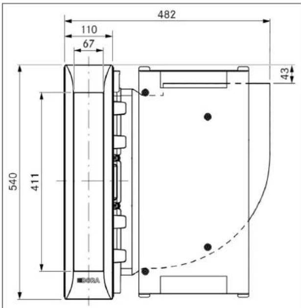
Fig. 3.1 PKA3/PKA3AB appliance dimensions from above

Fig. 3.2 PKA3/PKA3AB appliance dimensions front view

Fig. 3.3 PKA3/PKA3AB appliance dimensions side view

Fig. 3.4 Control unit dimensions
3.2 Cooktop extractor system with integrated fan PKAS3/PKAS3AB
| Parameter Value |
| Supply voltage 220-240 V |
| Frequency 50-60 Hz |
| Power consumption (incl. additional universal fans) 550 W |
| Dimensions (width x depth x height) 468 x 540 x 199 mm |
| Weight (incl. accessories and packaging) 12.5 kg |
| Cooktop extractor |
| Power levels 1-9, P |
Tab. 3.2 Technical data for PKAS3/PKAS3AB
PKAS3/PKAS3AB appliance dimensions

Fig. 3.5 PKAS3/PKAS3AB appliance dimensions from above

Fig. 3.6 PKAS3/PKAS3AB appliance dimensions front view
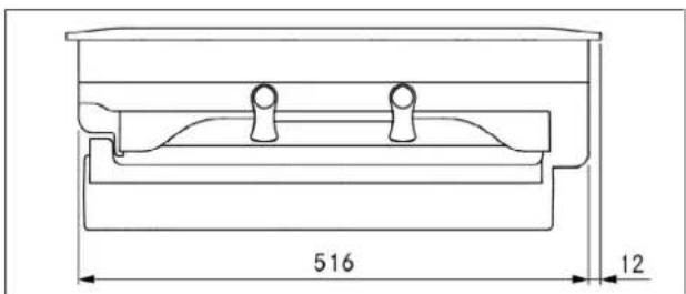
Fig. 3.7 PKAS3/PKAS3AB appliance dimensions side view
3.3 Surface induction cooktop PKFI3
| Parameter Value | |
| Supply voltage 220-240 V | |
| Frequency 50-60 Hz | |
| Power consumption 3680 W | |
| Fuse protection 1 x 16 A | |
| Cooktop dimensions 370 x 540 x 52 mm | |
| Weight (incl. accessories and packaging) 8.1 kg | |
| Cooktop | |
| Power levels 1-9, P | |
| Heat retention levels 3 | |
| Front cooking zone size 230 x 230 mm | |
| Front cooking zone output 2100 W | |
| Front cooking zone power setting output 3680 W | |
| Rear cooking zone size 230 x 230 mm | |
| Rear cooking zone output 2100 W | |
| Rear cooking zone power setting output 3680 W | |
| Power consumption (calculated with standard pot sizes) | |
| Front cooking zone (150 mm) | 185.0 Wh/kg |
| Rear cooking zone (180 mm) | 176.5 Wh/kg |
| Cooking zones bridged (210 mm) | 204.4 Wh/kg |
| Total (average) | 188.6 Wh/kg |
Tab. 3.3 Technical data for PKFI3
PKFI3 appliance dimensions

Fig. 3.8 PKFI3 appliance dimensions from above

Fig. 3.9 PKFI3 appliance dimensions front view
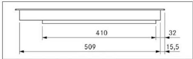
Fig. 3.10 PKFI3 appliance dimensions side view
3.4 Induction cooktop PKI3
| Parameter Value | |
| Supply voltage 220-240 V | |
| Frequency 50-60 Hz | |
| Power consumption 3680 W | |
| Fuse protection 1 x 16 A | |
| Cooktop dimensions 370 x 540 x 52 mm | |
| Weight (incl. accessories and packaging) 8.0 kg | |
| Cooktop Value | |
| Power levels 1-9, P | |
| Heat retention levels 3 | |
| Front cooking zone size ∅ 230 mm | |
| Front cooking zone output 2300 W | |
| Front cooking zone power setting output 3680 W | |
| Rear cooking zone size ∅ 165 mm | |
| Rear cooking zone output 1400 W | |
| Rear cooking zone power setting output | 2200 W |
| Power consumption (calculated with standard pot sizes) | |
| Front cooking zone (240 mm) | 162.7 Wh/kg |
| Rear cooking zone (180 mm) | 169.3 Wh/kg |
| Total (average) | 166.0 Wh/kg |
Tab. 3.4 Technical data for PKI3
PKI3 appliance dimensions

Fig. 3.11 PKI3 appliance dimensions from above
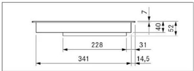
Fig. 3.12 PKI3 appliance dimensions front view

Fig. 3.13 PKI3 appliance dimensions side view
3.5 Induction wok cooktop PKIW3
| Parameter Value | |
| Supply voltage 220-240 V | |
| Frequency 50-60 Hz | |
| Power consumption 3000 W | |
| Fuse protection 1 x 16 A | |
| Cooktop dimensions 370 x 540 x 128 mm | |
| Weight (incl. accessories and packaging) 9.5 kg | |
| Cooktop | |
| Power levels 1-9, P | |
| Heat retention levels 3 | |
| Cooking zone size | ∅ 310 mm |
| Cooking zone output | 2400 W |
| Cooking zone power setting output | 3000 W |
Tab. 3.5 Technical data for PKIW3
PKIW3 appliance dimensions

Fig. 3.14 PKIW3 appliance dimensions from above

Fig. 3.15 PKIW3 appliance dimensions front view

Fig. 3.16 PKIW3 appliance dimensions side view
3.6 HiLight cooktop, 3-ring/2-ring PKC3
| Parameter Value | |
| Supply voltage 380-415 V 2N~ | |
| Frequency 50-60 Hz | |
| Power consumption 4400 W | |
| Fuse protection 2 x 16 A | |
| Cooktop dimensions 370 x 540 x 73 mm | |
| Weight (incl. accessories and packaging) 8.7 kg | |
| Cooktop | |
| Power levels 1-9, 2-ring, 3-ring | |
| Heat retention levels 3 | |
| Front cooking zone size ∅ 120mm | |
| Front cooking zone output 800 W | |
| Front cooking zone 2-ring additional switching size ∅ 180mm | |
| Front cooking zone 2-ring additional switching output 1600 W | |
| Front cooking zone 3-ring additional switching size ∅ 235mm | |
| Front cooking zone 3-ring additional switching output 2500 W | |
| Rear cooking zone size ∅ 120 mm | |
| Rear cooking zone output 800 W | |
| Rear cooking zone 2-ring additional switching size ∅ 200mm | |
| Rear cooking zone 2-ring additional switching output 1900 W | |
| Power consumption (calculated with standard pot sizes) | |
| Front cooking zone (240 mm) 180.1 Wh/kg | |
| Rear cooking zone (210 mm) 189.0 Wh/kg | |
| Total (average) 184.6 Wh/kg |
Tab. 3.6 Technical data for PKC3
PKC3 appliance dimensions

Fig. 3.17 PKC3 appliance dimensions from above

Fig. 3.18 PKC3 appliance dimensions front view

Fig. 3.19 PKC3 appliance dimensions side view
3.7 HiLight cooktop, 3-ring/roaster PKCB3
| Cooktop Value | |
| Supply voltage 380-415 V 2N~ | |
| Frequency 50-60 Hz | |
| Power consumption 5100 W | |
| Fuse protection 2 x 16 A | |
| Cooktop dimensions 370 x 540 x 73 mm | |
| Weight (incl. accessories and packaging) 8.9 kg | |
| Cooktop | |
| Power levels 1-9, 2-ring, 3-ring, roaster | |
| Heat retention levels 3 | |
| Front cooking zone size ∅ 120mm | |
| Front cooking zone output 800 W | |
| Front cooking zone 2-ring additional switching ∅ 180mm size | |
| Front cooking zone 2-ring additional switching output | 1600 W |
| Front cooking zone 3-ring additional switching ∅ 235mm size | |
| Front cooking zone 3-ring additional switching output | 2500 W |
| Rear cooking zone size ∅ 165 mm | |
| Rear cooking zone output 1500 W | |
| Cooking zone roaster additional switching size 290 x 165 mm | |
| Cooking zone roaster additional switching output | 2600 W |
| Power consumption (calculated with standard pot sizes) | |
| Front cooking zone (240 mm) | 180.6 Wh/kg |
| Rear cooking zone (180 mm) | 189.5 Wh/kg |
| Total (average) | 185.1 Wh/kg |
Tab. 3.7 Technical data for PKCB3
PKCB3 appliance dimensions

Fig. 3.20 PKCB3 appliance dimensions from above

Fig. 3.21 PKCB3 appliance dimensions front view
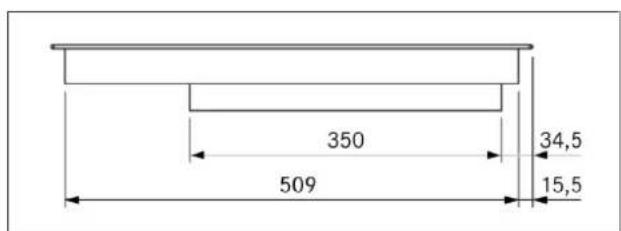
Fig. 3.22 PKCB3 appliance dimensions side view
3.8 Hyper cooktop, 1-ring/2-ring PKCH3
| Parameter Value | |
| Supply voltage 380-415 V 2N~ | |
| Frequency 50-60 Hz | |
| Power consumption 5100 W | |
| Fuse protection 2 x 16 A | |
| Cooktop dimensions 370 x 540 x 73 mm | |
| Weight (incl. accessories and packaging) 8.7 kg | |
| Cooktop | |
| Power levels 1-9, Hyper level, 2-ring additional switching | |
| Heat retention levels 3 | |
| Front cooking zone size ∅ 235 mm | |
| Front cooking zone output 2100 W | |
| Hyper level output 3200 W | |
| Rear cooking zone size ∅ 120 mm | |
| Rear cooking zone output 800 W | |
| Rear cooking zone 2-ring additional switching size ∅ 200 mm | |
| Rear cooking zone 2-ring additional switching output 1900 W | |
| Power consumption (calculated with standard pot sizes) | |
| Front cooking zone (240 mm) | 175.9 Wh/kg |
| Rear cooking zone (210 mm) | 189.1 Wh/kg |
| Total (average) | 182.5 Wh/kg |
Tab. 3.8 Technical data for PKCH3
PKCH3 appliance dimensions

Fig. 3.23 PKCH3 appliance dimensions from above
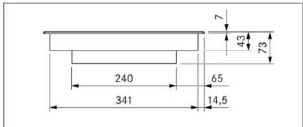
Fig. 3.24 PKCH3 appliance dimensions front view
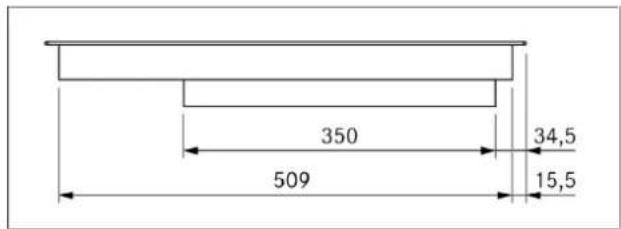
Fig. 3.25 PKCH3 appliance dimensions side view
3.9 Tepan stainless steel grill PKT3
| Parameter Value |
| Supply voltage 380-415 V 2N~ |
| Frequency 50-60 Hz |
| Power consumption 4800 W |
| Fuse protection 2 x 16 A |
| Cooktop dimensions 370 x 540 x 73 mm |
| Weight (incl. accessories and packaging) 15.8 kg |
| Cooktop |
| Temperature control (power levels) 80-250°C (250°C = P) |
| Front cooking zone size 295 x 230 mm |
| Front cooking zone output 2400 W |
| Rear cooking zone size 295 x 230 mm |
| Rear cooking zone output 2400 W |
| Temperature control range 70 - 250 °C |
Tab. 3.9 Technical data for PKT3
PKT3 appliance dimensions

Fig. 3.26 PKT3 appliance dimensions from above

Fig. 3.27 PKT3 appliance dimensions front view

Fig. 3.28 PKT3 appliance dimensions side view
3.10 Gas cooktop PKG3
| Parameter Value | |
| Supply voltage 220-240 V | |
| Frequency 50-60 Hz | |
| Total burner output 5000 W | |
| Power rating 20 W | |
| Fuse protection 1 x 0.5 A | |
| Gas connection 1/2" internal thread | |
| Cooktop dimensions 370 x 540 x 73 mm | |
| High-power burner pan support dimensions 270 x 270 x 25/50 mm | |
| Normal burner pan support dimensions 235 x 235 x 25/50 mm | |
| Weight (incl. accessories and packaging) 11.5 kg | |
| Cooktop | |
| Power levels 1-9, P | |
| Heat retention levels 3 | |
| High-power burner 800-3000 W | |
| Normal burner 550-2000 W | |
| Total nominal connection values G20/20 mbar: | 5000 W | 0.449 m3/h |
| Cooktop energy consumption G20/20 mbar | |
| High-power burner 60.0% | |
| Normal burner 60.0% | |
| Cooking zones bridged | 60.0% |
Tab. 3.10 Technical data for PKG3
PKG3 appliance dimensions

Fig. 3.29 PKG3 appliance dimensions from above

Fig. 3.30 PKG3 appliance dimensions front view

Fig. 3.31 PKG3 appliance dimensions side view
3.11 Control knob
| Parameter Value | |
| Dimensions (width x depth x height) | 49 mm x 92 mm |
Tab. 3.11 Technical data for control knob
Control knob dimensions

Fig. 3.32 Control knob

Fig. 3.33 Control knob dimensions
4 Installation
▶ Observe all safety and warning information (see "2 Safety").
▶ Follow the enclosed manufacturer's information.
4.1 General installation instructions
The appliance must not be installed above cooling devices, dishwashers, stoves, ovens, washing machines or dryers.
The contact surfaces of the worktops and wall sealing strips must be made of a heat-resistant material (up to approx. 100 °C).
Worktop cut-outs must be moisture-sealed using suitable means and, where necessary, fitted with a thermal insulator.
External devices may only be connected to the cooktop extractor connections provided.
i Extremely bright lights aimed directly at the appliances can cause colour variations in the appliances and are thus to be avoided.
All packaging must be removed before using the appliance for the first time.
General installation instructions for cooktops
▶ Make sure that the area below the cooktop has a sufficient air supply.
To maintain the level of performance, sufficient ventilation below cooktops must be ensured.
The performance is affected or the cooktops overheat if the warm air beneath the cooktops cannot escape.
In the event of overheating, the cooktop power is reduced or the appliance is switched off completely.
If cable protection (false floor) is planned beneath the appliance, this must be fitted so it does not obstruct ventilation.
Additional installation instructions for Australia and New Zealand (AU/NZ):
The gas hose must be checked every 5 years and replaced if necessary. The gas hose must meet the requirements of AS/NZS 1869.
Restricted functions when using the cooktops without a cooktop extractor
If cooktops are installed and operated without a cooktop extractor, only limited functions will be available. The following functions will not be available:
- System functions
- Pause function
- Short-time timer
- Child lock
- All settings/functions in the configuration menu
4.1.1 Operating the cooktop extractor in the exhaust air mode and where there is a fireplace dependent upon the air supply in the room
National and regional laws and regulations must be observed with regard to the exhaust duct design.
A sufficient air supply must be ensured.
Fireplaces that depend on the air in the room (e.g. gas, oil, wood or coal-fired heaters, continuous-flow water heaters, instantaneous water heaters) draw in air from the room in which they are installed and release the exhaust fumes into the outside air via an exhaust system (e.g. chimney).
If the cooktop extractor is used in exhaust air mode, it draws in air from the room in which it is installed as well as from neighbouring rooms. Without sufficient air, there will be a drop in air pressure. Toxic gases could be drawn out of the chimney or extraction ducting and back into the room.
![graph TD A["X"] --> B["Y"] B --> C["Circle with arrow"] C --> D["Arrow to Y"] D --> E["Arrow to X"]](/content/2026/07/1498813/images/c5317ca144137f59a737448456b6989d108944b7fb3efd721964502037bc25a9.jpg)
Fig. 4.1 Exhaust air installation – not permitted

Fig. 4.2 Exhaust air installation – correct
▶ If simultaneously operating both a fireplace and the cooktop extractor in the same room, ensure that:
- the maximum low pressure is 4 Pa (4 x 10⁻⁵ bar);
- a safety device (e.g. window contact switch, low pressure warning device) is used to ensure that a sufficient supply of fresh air is guaranteed;
- the exhaust air is not channelled into a chimney that is used for exhaust gases of appliances operated with gas or other combustibles;
- the installation is checked and approved by an authorised certified engineer (e.g. heating engineer).
- when using a window contact switch, only devices will be installed which meet the requirements of standard IEC 60730-1:2013 + AMD1:2015 or EN 60730-1:2016 (or a more recent IEC update or EN standard) for type 2 control units and devices (e.g. window contact switch UFKS).
No window contact switches may be installed that separate the control unit from the power supply (phase separation). Only the Home In interface is to be used
If the cooktop extractor is used exclusively in recirculation mode, operation with an open fireplace is possible without any additional safety measures.
4.2 Checking the scope of delivery
Checking the scope of delivery
▶ Make sure the delivery is complete and check it for damage.
▶ Immediately inform the BORA Service TeamTeam if parts are missing or damaged.
▶ Do not under any circumstances install parts which are damaged.
▶ Dispose of transport packaging in the proper manner (see "5 Decommissioning, disassembly and disposal").
4.2.1 Scope of delivery of the cooktop extractor
| Scope of delivery Quantity | |
| Operating instructions 1 | |
| Installation instructions 1 | |
| Cooktop extractor 1 | |
| Height adjustment plate set 1 | |
| Installation clamps 4 | |
| Control knob 1 | |
| Stainless steel grease filter 1 | |
| Filter tray 1 | |
| Maintenance tray 1 | |
| Cover flap 1 | |
| Power supply cable 1 | |
| Control knob cable 1 | |
| Additional scope of delivery for PKA3/PKA3AB | |
| CAT 5e communication cable 1 | |
| Control unit 1 | |
| Duct piece | 1 |
| Seal | 1 |
Tab. 4.1 Scope of delivery
4.2.2 Scope of delivery of the cooktops
| Scope of delivery Quantity | |
| Operating instructions 1 | |
| Installation instructions 1 | |
| Cooktop | 1 |
| Height adjustment plate set 1 | |
| Fixing screws | 4 |
| Mounting brackets 4 | |
| Control knob 2 | |
| Control knob cable 2 | |
| Cooktop-to-cooktop-extractor communication cable | 1 |
| Additional scope of delivery for Tepan | |
| Tepan spatula | 1 |
| Additional scope of delivery for gas cooktop | |
| Cast-iron pan support | 2 |
| Nozzle set G20/20 mbar natural gas PKGDS2020 | 1 |
| Cylindrical/conical transition piece | 1 |
| Seal | 1 |
| Additional scope of delivery for Australia and New Zealand: | |
| 1.00 kPa gas regulator with test-point adapter for natural gas (NG) | 1 |
| Flexible gas connection hose, length 500 mm, 1/2" external thread (AS/NZS 1869) | 1 |
| Test-point adapter for liquified petroleum gas (LPG) | 1 |
| G20/10 mbar nozzle set (NG/1.0 kPa) - pre-installed | 1 |
| G31/27.5 mbar nozzle set (ULPG/2.75 kPa) | 1 |
Tab. 4.2 Scope of delivery
4.3 Tools and aids
The following tools, among others, are required to correctly install the cooktop:
- pencil
- tape measure or folding metre stick
• conventional or battery-operated drill - ∅50 mm centre bit
- black, heat-resistant silicone sealant
- slotted screwdriver
• size 10 Torx screwdriver/key
• size 20 Torx screwdriver key
4.4 Assembly instructions
4.4.1 Installation clearances
▶ Observe the required clearance around the worktop cut-out.

Fig. 4.3 Required clearance
[1] Required clearance
[2] Worktop cut-out
[*] 650 mm in the case of gas cooktops
4.4.2 Minimum installation dimensions

Fig. 4.4 Minimum installation dimensions for standard set-up of PKA3/PKA3AB

Fig. 4.5 Appliance installation dimensions for standard set-up of PKA3/PKA3AB with round silencer
4.4.3 Worktop
▶ Create the worktop cut-out taking into account the specified cut-out dimensions.
▶ Make sure that the cut surfaces of the worktops are properly sealed.
▶ Comply with the instructions of the worktop manufacturer.
4.4.4 Kitchen units
- Cross bars on the kitchen unit in the area of the worktop cut-out may need to be removed.
-
No false floor is necessary below the cooktop. If cable protection (false floor) is planned, the following must be taken into account:
-
It must be able to be removed for maintenance work.
-
To ensure sufficient cooktop ventilation, a minimum distance of 15 mm to the bottom edge of the cooktop extractor is to be observed.
-
The drawers and/or shelves in the floor unit must be removable.
- For correct installation, the drawers of the floor unit must be shortened depending on the installation situation.
4.4.5 Special assembly instructions for the gas cooktop
Taking into account the applicable valid regulations, the cooktop must be connected to the gas line with an upstream stopcock.
The connection between the gas cooktop and the gas connection must be provided at the installation site.
The hose connection must be laid in such a way that it is not subject to deformation, buckling or abrasion.
The stopcock and gas supply pipe connections must be accessible.
The pressure regulator must correspond to the set gas type and set gas pressure and must meet local and legal requirements.
The gas connection hose line must not come into contact with smoke or the flue outlet of an oven.
The hose line must not come into contact with hot surfaces on the cooktop or other devices.
Positioning of the gas cooktop with two cooktop extractors
If the gas cooktop is used in a model with two cooktop extractors, it is to be installed at the side. If installed between the cooktop extractors, the pull of air on both sides may affect the flames.
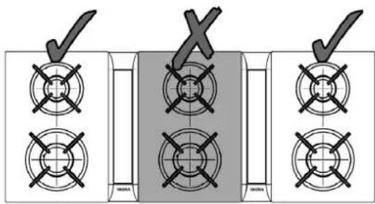
Fig. 4.6 Positioning of the gas cooktop with two cooktop extractors
Air supply for the gas cooktop
To ensure a sufficient air supply, an opening cross-section of at least 50 cm2 is required in the front of the kitchen unit, or an opening cross-section of at least 150 cm2 in the plinth area.
▶ Make sure that the area below the cooktop has a sufficient air supply.

Fig. 4.7 Air supply at front of the unit
[1] Air supply via the front of the unit (opening cross-section ≥50 cm2 )
[2] Optional cable protection (shortened)
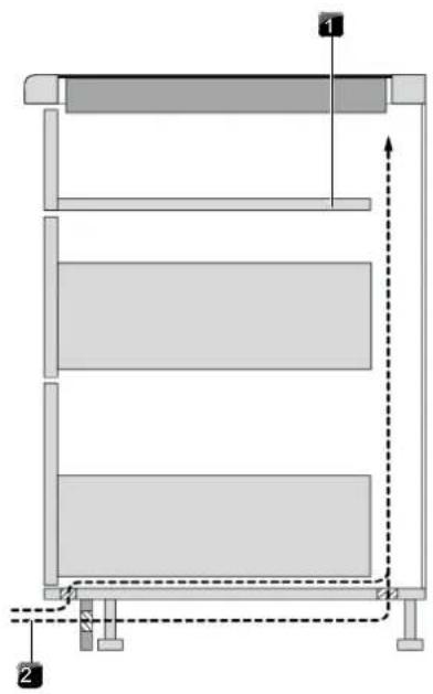
Fig. 4.8 Plinth area air supply
[1] Optional cable protection (shortened)
[2] Air supply via the plinth area (opening cross-section ≥ 150 cm 2 )
4.4.6 Return flow of recirculated air
In the case of recirculation systems, a return flow aperture must be provided in the kitchen unit to guide the clean recirculated air out of the unit and back into the room. The return flow aperture can be created above a shortened plinth. A slatted plinth with at least the minimum opening cross-section can also be used.
▶ Decrease the height of the plinth panel or create corresponding openings in the plinth.
The cross-section of the return flow aperture must be ≥ 500cm2 ( ≥ 1000cm2 in the case of gas appliances) for each cooktop extractor.
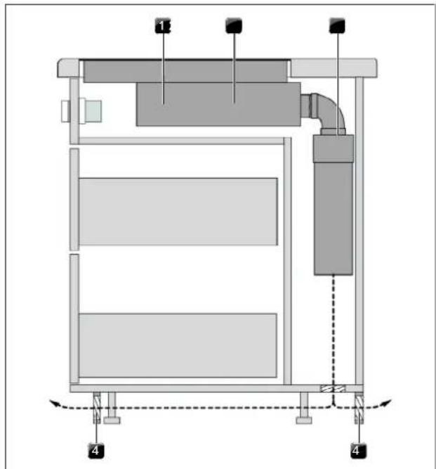
Fig. 4.9 Example of recirculated-air-return-flow planning
[1] Cooktop
[2] Cooktop extractor
[3] Air cleaning box
[4] Return flow aperture
If several cooktop extractors need to be installed in recirculation mode, the return flow apertures must be enlarged.
Example: 2 recirculation systems = 2 x (>500 cm 2 )
Example: 2 recirculation systems with gas cooktop = 2 x (>1000 cm 2 )

If the gas flame goes out, is excessively affected by the extractor and/or the flame is not as it should be (e.g. soot production, flame blowback, etc.), the return flow aperture must be enlarged.
4.5 Cut-out dimensions
4.5.1 Worktop overhang
Please note the worktop overhang x when creating the worktop cut-out. Applies to flush installation and surface mounting.

Fig. 4.10 Worktop overhang
4.5.2 Flush installation

Fig. 4.11 Cut-out dimensions for flush installation

Fig. 4.12 Rebate dimensions for flush installation

Tab. 4.3 Cut-out dimensions of the appliance combinations in the case of flush installation
4.5.3 Surface mounting

Fig. 4.13 Cut-out dimensions for surface mounting

Fig. 4.14 Overlay dimensions for surface mounting
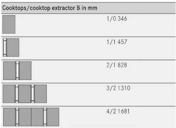
Tab. 4.4 Cut-out dimensions of the appliance combinations in the case of surface mounting
4.6 Control knob installation
▶ Pre-drill all bore holes to prevent tearing out the fixed front panel.

Fig. 4.15 Installed control knob
4.6.1 Cooktop extractor bore holes

Fig. 4.16 Cooktop extractor drilling pattern
[1] Cooktop extractor
[2] Worktop
[3] Fixed front panel
4.6.2 Cooktop bore holes

Fig. 4.17 Cooktop drilling pattern
[1] Cooktop
[2] Worktop
[3] Fixed front panel
Wok cooktop with 1 control knob

Fig. 4.18 Drilling pattern for wok cooktop with 1 control knob
[1] Wok cooktop PKIW3
[2] Worktop
[3] Fixed front panel
4.6.3 Example bore holes

Fig. 4.19 Drilling pattern for 2 cooktops, 1 cooktop extractor and 2 sockets
[1] Boreholes for socket (x 2 external)
[2] Bore holes for control knobs (x 5)
[3] Cooktop (x 2)
[4] Cooktop extractor
[5] Worktop
[6] Fixed front panel

Fig. 4.20 Drilling pattern for 3 cooktops, 2 cooktop extractors and 2 sockets
[1] Boreholes for socket (x 2 external)
[2] Bore holes for control knobs (x 8)
[3] Cooktop (x 3)
[4] Cooktop extractor (x 2)
[5] Worktop
[6] Fixed front panel
4.6.4 Fitting the control knob
▶ Remove the knob ring.
▶ Unscrew the universal nut.
▶ Remove the wave spring.
▶ Insert the knob housing from the front through the hole in the panel.
▶ Attach the wave spring to the knob housing.
- In the case of steel fronts, wave springs must not be used.
▶ Screw the universal nut onto the knob housing from the rear and tighten a little.
▶ Align the knob housing so it is level.
▶ Tighten the universal nut.
- The wave spring must be pressed flat.
▶ Remove the sticker.
▶ Place the knob ring on the knob housing.

Fig. 4.21 Structure of control knob
[1] Knob housing
[2] Universal nut
[3] Sticker
[4] Knob ring
[5] Wave spring

Fig. 4.22 Fitting the control knob

Fig. 4.23 Wave spring when installation is complete
4.7 Planning variations for PKA3/PKA3AB
With the PKA3/PKA3AB cooktop extractor, the air can be channelled off to the left or to the right, according to requirements. Thanks to the pre-assembled curved duct piece or the straight duct piece (included in the scope of delivery) the air can be channelled around a 90° bend to the rear or straight out to the side. When using the straight duct piece, an additional EFD shallow seal is required (not included in the scope of delivery). The cooktop extractor is delivered with a pre-assembled curved duct piece to the right.
4.7.1 Airflow straight to the side
When the air is channelled straight out to the side, the cooktop can be installed rotated by 180°. In this case, the cover frame must also be rotated.
▶ Unscrew the Torx screw that attaches the holding plate to the curved duct piece.
▶ Unscrew the 2 Torx screws that attach the holding plate to the duct piece adapter.
▶ Remove the holding plate.
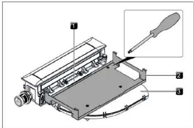
Fig. 4.24 Removing the holding plate
[1] Duct piece adapter
[2] Holding plate
[3] Curved duct piece
[1] Duct piece adapter
[2] Holding plate
[3] Curved duct piece
Separate the curved duct piece from the duct piece adapter.
▶ To do this, carefully prise the plug connection open with a slotted screwdriver first.
▶ Pull the curved duct piece out.
▶ If necessary, rotate the cover frame by 180° .
Separate the curved duct piece from the duct piece adapter.
▶ To do this, carefully prise the plug connection open with a slotted screwdriver first.
▶ Pull the curved duct piece out.
▶ If necessary, rotate the cover frame by 180° .

Fig. 4.25 Disassemble the curved duct piece
[1] Curved duct piece
[2] Duct piece adapter
▶ Push the straight duct piece onto the duct piece adapter until it clicks into place in the fastening lugs.
▶ Make sure that no air gap has formed between the components.
▶ Attach the holding plate to the duct piece adapter with 2 screws only.

Fig. 4.26 Installing the straight duct piece
[1] Straight duct piece
[2] Duct piece adapter
4.7.2 Airflow towards the left
The PKA3/PKA3AB cooktop can be installed rotated by 180°, meaning that the air is channelled away to the left.
▶ Remove the holding plate and the curved duct piece.
▶ Rotate the cover frame by 180° .
▶ Turn the curved duct piece over.
▶ Push the rotated curved duct piece back onto the duct piece adapter until it clicks into place in the fastening lugs.

Fig. 4.27 Turning the curved duct piece over
[1] Curved duct piece
[2] Duct piece adapter
▶ Make sure that no air gap has formed between the components.
▶ Attach the holding plate.

Fig. 4.28 Airflow to the left with the curved duct piece
4.7.3 Rotating the cover frame by 180°
To ensure correct orientation of the cover frame, this must also be rotated by 180° .
▶ Turn the cooktop extractor round and lay it carefully on a soft surface (e.g. a blanket) with the visible surface facing upwards.
▶ Carefully remove the holding clamps (x 18) with a screwdriver.

Fig. 4.29 Removing the cover frame
▶ Turn the cooktop extractor round and remove the cover frame.
▶ Rotate the cover frame by 180° .
▶ Put the cover frame back on the cooktop extractor.
▶ Make sure that the holding clamps click into place.
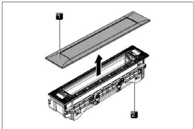
Fig. 4.30 Removing the cover frame
[1] Cover frame
[2] Cooktop extractor
4.8 Installing the cooktop extractor
Clearance of one millimetre should be planned between the built-in appliances. A clearance of two millimetres should be planned around the built-in appliances.
4.8.1 Fitting the cooktop extractor
▶ Place the cooktop extractor in the middle of the worktop cut-out provided.
▶ Position the cooktop extractor with precision.

Fig. 4.31 Fitting the cooktop extractor
[1] Worktop cut-out
[2] Cooktop extractor
▶ If applicable, insert the height adjustment plates.
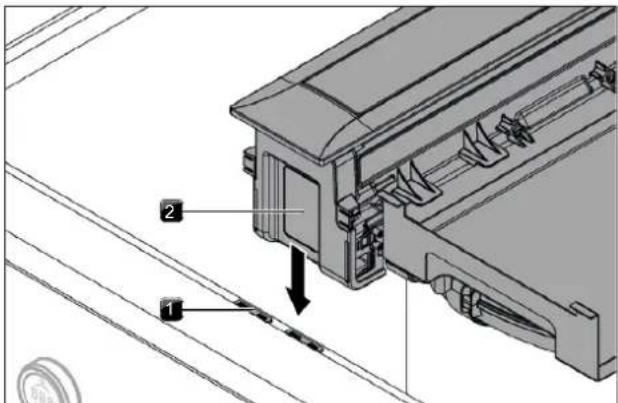
Fig. 4.32 Height adjustment plates
[1] Height adjustment plate
[2] Cooktop extractor
The cooktop extractor is to be installed 0.5 mm higher than the cooktops.

Fig. 4.33 Height difference
[1] Cooktop
[2] Cooktop extractor
4.8.2 Securing the cooktop extractor
Preparing the mounting brackets
The cooktop extractor is secured using the four mounting brackets provided. The symbols on the mounting brackets show which side to use for surface mounting and which to use for flush installation. The lettering shows the cutting mark corresponding to the worktop thickness.
▶ If necessary, shorten the mounting brackets according to the thickness of the worktop.
▶ To do this, cut the mounting brackets at the appropriate cut marks using a utility knife.
▶ Depending on the installation type, turn the mounting brackets to the left or right (flush installation or surface mounting).

Fig. 4.34 Mounting bracket - right side (flush installation)
[1] Worktop thickness lettering (in mm)
[2] Cut marks (x 4)
[3] Fastening lugs (2 on each side)
[4] Marking for flush installation

Fig. 4.35 Mounting bracket - left side (surface mounting)
[1] Worktop thickness lettering (in mm)
[2] Cut marks (x 4)
[3] Fastening lugs (2 on each side)
[4] Marking for surface mounting
Securing the cooktop extractor
▶ Push the mounting brackets into the holders provided on the cooktop extractor or the alternative positions on the holding plate.
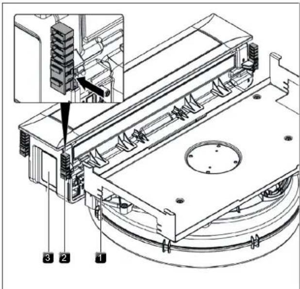
Fig. 4.36 Pushing on the mounting brackets
[1] Alternative position for mounting bracket
[2] Mounting bracket
[3] Cooktop extractor
▶ Use a Torx 20 screwdriver to tighten the mounting brackets slightly from underneath.
▶ Verify that the alignment is correct.

Fig. 4.37 Tightening the mounting clamps
4.9 Installing the duct system
BORA does not assume any liability for the installation of the Ecotube duct system. Fire safety requirements are to be clarified with the local authorities prior to installing the Ecotube duct system. If necessary, suitable shut-off devices must be used to meet the national requirements.
4.9.1 Duct connection dimensions

Fig. 4.38 Duct connection dimensions for PKA3/PKA3AB with the curved duct piece

Fig. 4.39 Duct connection dimensions for PKA3/PKA3AB with the curved duct piece

Fig. 4.40 Duct connection dimensions for PKA3/PKA3AB with the straight duct piece

Fig. 4.41 Duct connection dimensions for PKAS3, PKAS3AB
4.9.2 Preparing for installation
- The maximum exhaust air duct length with a fan is 6 m with six 90° bends installed.
- The minimum cross-section of the air ducts must be 176 cm 2 , which equates to a round pipe with a diameter of 150 mm or the BORA Ecotube duct system.
▶ Use only BORA Ecotube duct parts.
▶ Do not use flexible or fabric hoses.
The duct system must be fitted to the cooktop extractor free of load and with the power supply switched off.
▶ Adjust the ducting parts to the height of the worktop.
▶ Saw out the necessary cut-outs for the ducting in the back panel of the floor unit.
4.9.3 Connecting the duct system to the appliance
When attaching the seals, ensure that an airtight seal is created with the connecting duct piece when the seals are compressed.
▶ Push the seal onto the outlet nozzle on the appliance. To do this, the seal will need to be stretched slightly.
▶ Push the duct part to be connected with the coupling onto the outlet nozzle with the seal.
▶ Ensure that the seal is not displaced.

Fig. 4.42 Connecting to the duct system
[1] Exhaust opening
[2] Seal
[3] Duct piece
4.9.4 Standard set-up for PKA3/PKA3AB
The floor unit must not be supported by the plinth fan housing.
▶ Depending on the installation situation, adjust the levelling feet on the floor unit as necessary.
▶ Push the round seal onto the plinth fan inlet nozzle.
▶ Push the shallow seal onto the plinth fan outlet nozzle.
• To do this, the seals will need to be stretched slightly.

Fig. 4.43 Fitting the seals on the plinth fan
▶ Push the 90° diverter onto the curved duct piece.
▶ Position the plinth fan.
▶ To facilitate positioning, the inlet nozzle on the plinth fan can be removed. To do this, please see the assembly instructions for the Universal plinth fan ULS.
▶ Connect the silencer to the plinth fan.
▶ Connect the silencer to the 90° diverter.
- You can optimally stick the joins between the ducting sections and the plinth fan together with UDB sealing tape.
▶ Position the plinth fan and the control unit in such a way that they are easily accessible and removable for maintenance work.
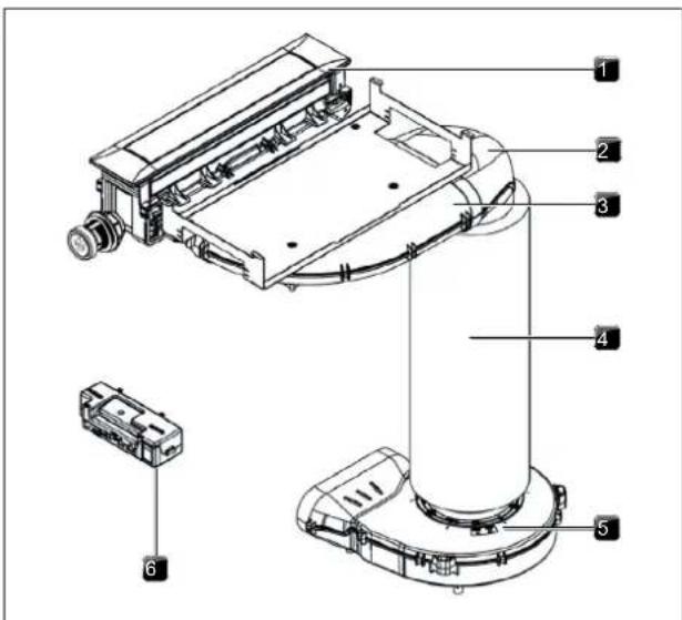
Fig. 4.44 Standard set-up for PKA3/PKA3AB
[1] Cooktop extractor
[2] 90° diverter
[3] Curved duct piece
[4] Silencer
[5] Universal plinth fan
[6] Control unit
4.9.5 Positioning the control unit
The control unit must be placed inside the kitchen unit. Position the control unit inside the kitchen unit in such a way that it cannot be freely accessed by the user (e.g. behind the plinth panel). When positioning the control unit please observe the length of the mains cable (1 m).
Permitted positions inside the kitchen unit:
- loose on a false floor
- loose on the shallow duct
- mounted on the kitchen unit
4.9.6 Installing the additional fan
The maximum exhaust air duct length with a fan is 6 m.
▶ Install an additional fan in the exhaust duct if necessary.
▶ Ensure that there is a clearance of at least 3 m between the fan units.
▶ Use only BORA Universal fans.
4.10 Gas installation
Assembly, installation and commissioning must always occur in line with national laws, regulations and standards. The work must be performed by qualified specialists who know and comply with the additional regulations of the local energy supply companies.
The gas must be connected before the cooktop is installed in the worktop.
4.10.1 Ventilation
This appliance is not connected to a flue gas evacuation device. It must be positioned and connected in accordance with the applicable installation conditions. Suitable ventilation measures must be particularly adhered to.
▶ Always ensure sufficient ventilation during operation (of the appliance).
4.10.2 Gas connection
The gas supply is connected to the appliance using a pre-installed elbow fitting with a 1/2" cylindrical internal thread. If, due to national regulations, a conical connection is required, the cylindrical/conical transition piece (provided) is to be used.

Fig. 4.45 Position of gas connection
4.10.3 Connecting the gas supply
▶ Turn off the gas supply.
▶ Switch off the main switch/automatic circuit breaker before connecting the cooktop.
▶ Secure the main switch/automatic circuit breaker against being switched back on without permission.
▶ Make sure the power to the appliance is disconnected.
▶ Check the gas type and gas pressure of the gas supply pipe.
▶ Ensure that the appliance is equipped with the correct nozzle type in order to guarantee a correct burner flame and safe operation.
▶ Remove the protective cap from the elbow fitting.
▶ Connect the appliance to the gas supply.
When the cooktop has been installed, use suitable testing equipment to check all the connections between the cooktop and the gas supply. There must not be any leaks.
▶ Create a leak test record and give this to the user.
4.10.4 Additional installation instructions for Australia and New Zealand (AU/NZ)
Observe the requirements for installing the appliance pursuant to AS/NZS 5601.1: minimum distance from the gas burner head to flammable surfaces.
i Installation may only be carried out by authorised staff.
▶ Furthermore, the requirements under current regulations and the latest version of AS/NZS 5601.1 are to be observed.
▶ Other technical requirements are to be taken into account: AS/NZS 5263.1.1 Gas appliances – domestic gas cooking appliances (AU/NZS).
▶ Please check the different scopes of delivery
- Any connection to a rigid pipe must be made pursuant to AS/NZS 5601.1.
- Pursuant to AS/NZS 1869 (certified according to AS/NZS 1869) the connection to a gas hose must have a diameter of 10 mm, be class B or D pursuant to AS/NZS 1869 and have a maximum length of 1200 mm pursuant to AS/NZS 5601.1.
Natural gas (NG)
If the cooktop is connected to a natural gas supply (NG), a gas regulator with a test-point adapter must be installed.
The gas regulator is included in the scope of delivery.
▶ Attach the gas regulator to the connection on the gas cooktop.
▶ Bear in mind the direction of the flow of gas through the gas regulator.

Fig. 4.46 Gas regulator (NG)
Liquified petroleum gas (LPG)
When switching from NG to ULPG, the sticker provided must be affixed
If the cooktop is connected to a liquified petroleum gas supply (LPG), the supply is adjusted at the gas bottle, so only the test-point adapter provided with the appliance needs to be fitted in the gas supply pipe.
▶ Attach the test-point adapter to the connection on the gas cooktop.

Fig. 4.47 Test-point adapter (LPG)
Test the gas pressure (LPG) as follows:
▶ Turn the knob to position 0.
▶ Turn off the gas supply.
▶ Unscrew the test-point adapter screw completely.
▶ Connect your measuring device to the test-point adapter connector.
▶ Turn on the gas supply.
▶ Set the gas pressure on the gas supply pipe (LPG pressure cylinder) to 2.75 kPa.
Light the burner.
▶ Check the burner flame.
▶ Turn off the gas supply when you have successfully set the pressure.
▶ Turn the knob to position 0.
▶ Unscrew the measuring device from the test point.
▶ Screw the test-point screw back into the test-point adapter.
▶ Ensure that the screw is fitted correctly.
4.10.5 Changing the gas type
▶ Turn off the gas supply to the gas supply pipe.
▶ Switch off the main switch/automatic circuit breaker.
▶ Secure the main switch/automatic circuit breaker against being switched back on without permission.
▶ Make sure the power to the appliance is disconnected.
Changing the gas burner nozzle in the gas burner
The nozzles regulate the maximum gas throughflow for each burner and gas type/pressure. The gas cooktop is set by default to natural gas G20/20 mbar (pre-assembled). If another type of gas is used, the configuration menu on the cooktop must be adjusted accordingly. Use only stamped and approved nozzles.
| Cat. | ||||
| I2E+ G20/G25: 20/25 mbar,BE, FR | ||||
| I2E G20:20 mbar,DE, LU, PL, RO | ||||
| I2EK G25.3: 25 mbar,NL | ||||
| I2L G25: 25 mbar,NL | ||||
| I2ELL G20/G25: 20/25 mbar,DE/LU | ||||
| I2H G20: 20 mbar,AT, CH, CZ, DK, EE, ES, FI, GB, GR, HR, IE, IT, LU, LT, LV,NO, PT, RO, SE, SI, SK, TR | ||||
| I3+ G30/G31: 28-30/37 mbar,BE, CH, CY, CZ, ES, FR, GB, GR, IE, IT, LT, PT, SI, TR | ||||
| I3B/P G30/31: 30 mbar,BE, CY, CZ, DK, EE, FI, FR, GB, GR, HR, IT, LT, NL, NO, PL,PT, RO, SE, SI, TR | ||||
| I3B/P G30/31: 50 mbar,AT, CH, DE, FR, SK | ||||
| I3P G31: 37 mbar,BE. CH, CZ, ES, FR, GB, GR, HR, IE, IT, LT, NL, PL, PT, SI,SK, TR | ||||
| II2E+3+ G20/G25: 20/25 mbar,G30/G31: 28-30/37 mbar,BE, FR | ||||
| II2EK3B/P G25.3: 25 mbar, G30/31: 30 mbar,NL | ||||
| II2ELL3B/P G20/G25/G30: 20/20/50 mbar,EN | ||||
| II2H3+ G20: 20 mbar,G30/31: 28-30/37 mbar,CH, CY, CZ, ES, GB, GR, IE, IT, LT, PT, SI, SK, TR | ||||
| II2H3B/P G20: 20 mbar,G30/G31: 30 mbar,CY, CZ, DK, EE, FI, GR, HR, IT, LT, NO, RO, SE, SI, SK, TR | ||||
| II2H3B/P G20: 20 mbar,G30/31: 50 mbarAT, CH, SK | ||||
| II2L3B/P G25: 25 mbar,G30/31: 30 mbarRO | ||||
| AT eingestellt: natural gas H 12H 20 mbar | ||||
| BE | eingestellt: | Erdgas E+ | 12E+ | 20 / 25 mbar |
| BE | ingesteld: | Aardgas E+ | 12E+ | 20 / 25 mbar |
| BE | reglage: | Gaz naturel E+ | 12E+ | 20 / 25 mbar |
| CH | eingestellt: | natural gas H | 12H | 20 mbar |
| CH | impostato | Gas metano | 12H | |
| CH | per: | H | 12H | |
| impostato | Gaz naturel H | |||
| per: | ||||
| CY ενεργοποιημένη: | φυσικό αέριοH | 20 mbar | ||
| CZ nastavenona: | Zemní plyn H 12H 20 mbar | |||
| EN eingestellt: Erdgas E 12H 20 mbar | ||||
| DK sat på: Naturgas H 12H 20 mbar | ||||
| EE sisse | Maagaas H 12H 20 mbar | |||
| lülitatud: | ||||
| ES ajustado: Gas natural H 12H 20 mbar | ||||
| FI asetettu: Maakaasu H 12H 20 mbar | ||||
| FR reglage: | Gaz naturel E+ | 12E+ | 20 / 25 mbar | |
| GB set for: | Natural gas H 12H 20 mbar | |||
| GR ενεργοποιημένη: | φυσικό αέριοH | 12H 20 mbar | ||
| HR uključeno: | Prirodni plinH | 12H 20 mbar | ||
| IE set for: | Natural gas H 12H 20 mbar | |||
| IS | sett á: | jarðgas H | 20 mbar | |
| IT aggiustato a: | Gas naturaleH | 12H 20 mbar | ||
| LT | nustatytas: Gamtinés dujos H | 12H 20 mbar | ||
| LU festgeluccht: | NatierlechGas E | 20 mbar | ||
| LV ieslēgts: | Dabasgāze H 12H 20 mbar | |||
| MT | issettjat fuq: | Gass naturaliH | 20 mbar | |
| NO | satt på: | Naturgass H | 12H 20 mbar | |
| PL | ustawić: | Gaz ziemny E 12H 20 mbar | ||
| PT | regulado para: | Gás natural H 12H 20 mbar | ||
| RO | setat pe: Gaz natural H 12H, 12E | 20 mbar | ||
| SE sätt på: | Naturgas H 12H 20 mbar | |||
| SI | nastavljen na: | Zemeljski plin H | 12H 20 mbar | |
| SK zapnuté: | Zemný plyn H 12H 20 mbar | |||
| TR ayarlamak: | Doğal gaz H 12H 20 mbar | |||
Tab. 4.5 Overview of gas categories
Tab. 4.6 Gas cooktop default settings
The stamp on the nozzles corresponds to the values in the nozzle table and can be found either on the top or side of the nozzles.
| Gas type/gas pressure mbar | ∅ SR burner/normal burner | ∅ R burner/high-power burner |
| G20/20 | 104 | 125 |
| G25/20 | 110 | 131 |
| G20/13 | 115 | 149 |
| G25/25 | 104 | 131 |
| G25.3/25 | ||
| G20/25 | 100 | 119 |
| G30/37 | 69 | 85 |
| G31/37 | ||
| G30/50 | 62 | 78 |
| G30-50 mbar |
Tab. 4.7 Nozzle table
Total nominal connection values for liquid gas:
| Gas type | mbar | kW | g/h | m3/h |
| G30/G31 | 50 4.90 | 364 | 0.143 | |
| G30 | 29 5.00 | 364 | 0.143 |
Tab. 4.8 Liquid gas nominal connection values
Total nominal connection values for natural gas:
| Gas type | mbar kW | m3/h | |
| G20 | screwdriver | 5.00 | 0.48 |
| G25 | 25 | 5.10 | 0.55 |
| G25.3 25 | 5.10 | 0.54 | |
| G20 | 13 | 5.00 | 0.48 |
| G25 | 20 | 4.80 | 0.55 |
Tab. 4.9 Natural gas nominal connection values
Special nozzle table for Australia and New Zealand:
| Gas type/gas pressure mbar | ∅ SR burner/normal burner | ∅ R burner/high-power burner |
| NG/1.0 kPa (G20/10) | 1.22 | 1.55 |
| ULPG/2.75 kPa (G31/27.5) | 0.75 | 0.92 |
Tab. 4.10 Nozzle table (Australia and New Zealand)
| Total nominal connection value for ULPG/2.75 kPa test-point pressure: | 18.6 Mj/h |
| Cooktop energy consumption AU/NZ - ULPG/2.75 kPa test-point pressure: | |
| High-power burner | 11.2 Mj/h |
| Normal burner | 7.4 Mj/h |
| Total nominal connection value for NG/1.0 kPa test- point pressure: | 19.5 Mj/h |
| Cooktop energy consumption AU/NZ - NG/1.00 kPa test-point pressure: | |
| High-power burner | 12.0 Mj/h |
| Normal burner | 7.5 Mj/h |
▶ Remove the pan support.
▶ Remove the burner cap from the burner head.
▶ Remove the burner head from the gas outlet.

Fig. 4.48 Gas burner structure
[1] Burner cap
[2] Burner head
[3] Electric igniter
[4] Safety thermocouple
[5] Burner housing
[6] Gas burner nozzle
▶ Unscrew the gas burner nozzle from the gas burner
▶ Screw the corresponding nozzle for the gas type to be used into the gas burner.
▶ Put the burner parts back together again.
▶ Position the burner head correctly on the gas outlet.
▶ Ensure that the safety thermocouple and the electric igniter are positioned in the correct opening.
▶ Position the burner cap so that it fits perfectly, sitting straight on the burner head.
- If burner parts are not positioned correctly, the electric igniter will not work.
▶ Place the pan support straight on the gas burner so it fits perfectly.
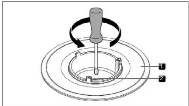
Fig. 4.49 Cooktop burner with gas burner nozzle
[1] Gas burner
[2] Gas burner nozzle
▶ Set the gas type in the configuration menu.
Affixing the nozzle set nameplates
Affix the nozzle set nameplates included in the scope of delivery in the corresponding space over the nozzle set nameplate on the bottom of the cooktop and on the penultimate page of the operating instructions.

Fig. 4.50 Affixing the nozzle set nameplates
4.11 Installing the cooktops
Clearance of one millimetre should be planned between the built-in appliances. A clearance of two millimetres should be planned around the built-in appliances.
The cooktop can also be installed rotated by 180°.
4.11.1 Preparing the cooktop extractor when using the wok cooktop
If a cooktop extractor is right next to a wok cooktop, the plastic bar on the side of the cooktop extractor must be carefully removed.
▶ Carefully remove the plastic bar from the side of the cooktop extractor.
▶ To do this, use a utility knife or similar suitable tool.

Fig. 4.51 Plastic bar on the side of the cooktop extractor
[1] Plastic bar on the side
[2] Cooktop extractor
4.11.2 Installing the cooktop
When installing cooktops PKFI3 and PKI3, pay attention to the position of the cooktop display (alternatively, the cooktop can be installed rotated by 180°).
▶ Insert the cooktop into the worktop cut-out.
▶ Precisely align the cooktop.
For a normal installation, please note that the ports for the control knobs and the automatic extractor function are at the front.
The connection cables should be guided to the rear. Use the cable holders provided.

Fig. 4.52 Inserting the cooktop
[1] Control knob port and cooktop extractor interface (front)
[2] Cooktop
[3] Worktop cut-out
▶ If applicable, insert the height adjustment plates.

Fig. 4.53 Cooktop and height adjustment plates
[1] Cooktop
[2] Height adjustment plates
▶ Secure the appliance using the mounting brackets.
▶ Screw on the mounting brackets using the washer to a maximum of 2 Nm.
▶ Verify that the alignment is correct.

Fig. 4.54 Mounting brackets
[1] Mounting bracket
[2] Washer
[3] Screw
4.11.3 Installing the Tepan stainless steel grill
▶ Insert the Tepan stainless steel grill into the worktop cut-out.
▶ Precisely align the Tepan stainless steel grill.
For a normal installation, please note that the ports for the control knobs and the automatic extractor function are at the rear.

Fig. 4.55 Inserting the Tepan stainless steel grill
[1] Worktop cut-out
[2] Tepan stainless steel grill
[3] Control knob and automatic extractor function ports
▶ If applicable, insert the height adjustment plates.
▶ Secure the appliance using the mounting brackets.
▶ Screw on the mounting brackets using the washer to a maximum of 2 Nm.
▶ Verify that the alignment is correct.

Fig. 4.56 Mounting brackets
[1] Mounting bracket
[2] Washer
[3] Screw
[4] Screw (60 mm)
4.11.4 Cooktop installation rotated by 180°
When installing a cooktop with a cooktop extractor, the configuration cannot be changed to the installation set-up rotated by 180°.
Installation clearances for cooktops PKC3, PKCB3 and PKCH3 when installed rotated by 180°

Fig. 4.57 Required clearance
[1] Required clearance
[2] Worktop cut-out
Installation rotated by 180°
▶ For the installation, proceed as described above.
▶ Change the installation direction in the configuration menu (see "Configuration menu" in the operating instructions).
- If installation is rotated by 180° , the ports for the control knobs and the automatic extractor function are at the rear of the cooktops.
Gas cooktop installation rotated by 180°
▶ Rotate the gas elbow fitting 180° so that the supply can be connected to the rear.
Tepan stainless steel grill installation rotated by 180°
- If installation is rotated by 180°, then on the Tepan stainless steel grill PKT3 the ports for the control knobs and the automatic extractor function are at the front.
4.12 Connecting external switch contacts
The electronic unit can contain residual charge. You must therefore be careful not to touch the exposed contacts on the electronic unit.
When using Home In and Home Out, you will require the relevant documents for the external switch devices in order to ensure safe device connection and operation. The following switch contacts can be used:
| Contact Function Connection | |
| Home In Cooktop extractor on/off connection for external switch contact (contact closed: cooktop extractor on) | 12 V DC 100 mA |
| Home Out Electrically isolated contact for controlling external installations depending on the operating status of the cooktop extractor (cooktop extractor on: contact closed) | 250 V AC/30 V DC, 5 A maximum |
Tab. 4.11 Switch contacts
The Home-In contact can be used for external safety devices (e.g. window contact switches). If the switch is open, the cooktop extractor is off.
4.12.1 Preparing PKAS3/PKAS3AB
So that the top of the appliance is not scratched during installation, it must be placed on a protective base (e.g. cardboard).
▶ Spread out a base to protect the surface.
▶ Turn the cooktop extractor system over and lay it upside down on the base.
▶ Undo the control unit screws on the bottom of the cooktop extractor system.
▶ Remove the housing cover from the housing.
▶ Do not touch the electronic unit.

Fig. 4.58 Opening the control unit housing cover
[1] Housing cover
[2] Screw (x 3)
[3] Housing
[4] Electronic unit
4.12.2 Preparing the control unit on PKA3/PKA3AB
▶ Ensure that the control unit is disconnected from the power supply.
▶ Undo the screw on the housing cover.
▶ Carefully release all locks with a slotted screwdriver.
▶ Remove the housing cover from the housing subshell by lifting it up.
▶ Do not touch the electronic unit.

Fig. 4.59 Opening the control unit housing cover
[1] Housing cover
[2] Locks
[3] Housing subshell
[4] Screw
[5] Electronic unit
[1] Housing cover
[2] Locks
[3] Housing subshell
[4] Screw
[5] Electronic unit
4.12.3 Preparing connection cables for external switching equipment
Use connection cables of the following types to connect external switch devices.
Contact Connection cable
Home In H03VV-F 2 x 0.5mm 2
Home Out H05VV-F 2 x 1 mm²
Tab. 4.12 Connection cable
▶ Prepare the connection cable in accordance with the prescribed stripping lengths.
- The connection cable is only intended for internal use in buildings, private households, kitchens or offices!
- The overall length of the connection cable for external switching equipment must not exceed 10 m!
PKA3/PKA3AB
▶ Please adhere to the maximum stripping length of the individual wires of 9 mm on the stripped wire end.
▶ Please adhere to the maximum stripping length of the outer sheath of 25 mm on the insulated wire.
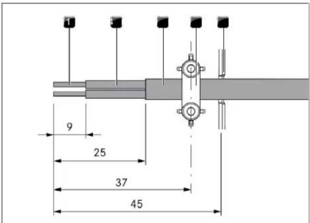
Fig. 4.60 Stripping lengths and installation position of the PKA3/PKA3AB connection cable
[1] Stripped wire end
[2] Insulated wire
[3] Jacketed cable
[4] Strain relief clamp
[5] Cable feed snap-out element
PKAS3/PKAS3AB
▶ Please adhere to the maximum stripping length of the individual wires of 9 mm on the stripped wire end.
▶ Please adhere to the maximum stripping length of the outer sheath of 21 mm (Home In) and 16.5 mm (Home Out) on the insulated wire.
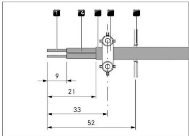
Fig. 4.61 Stripping lengths and installation position of the PKAS3/PKAS3AB connection cable - Home In
[1] Stripped wire end
[2] Insulated wire
[3] Jacketed cable
[4] Strain relief clamp
[5] Cable feed snap-out element
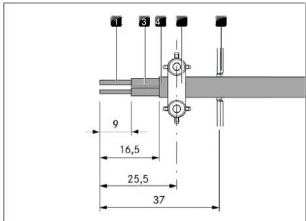
Fig. 4.62 Stripping lengths and installation position of the PKAS3/PKAS3AB connection cable - Home Out
[1] Stripped wire end
[2] Insulated wire
[3] Jacketed cable
[4] Strain relief clamp
[5] Cable feed snap-out element
4.12.4 Installing the external switch device
Depending on the type of switch device, connect the connection cables to either the Home In or the Home Out connection clamp.
▶ Adhere to the connection diagram when connecting Home In and Home Out.
▶ Connect the cable for the relevant contact to the switch contact clamp in accordance with the connection diagram.
- In order to connect the Home-In interface, the installed bridge must be removed.
- The Home In contact must be bridged if this is not used (bridged on delivery).
- For connections to the Home In connection clamp, no ferrules may be used.

Fig. 4.63 Connection diagram for the external switch contacts PKA3
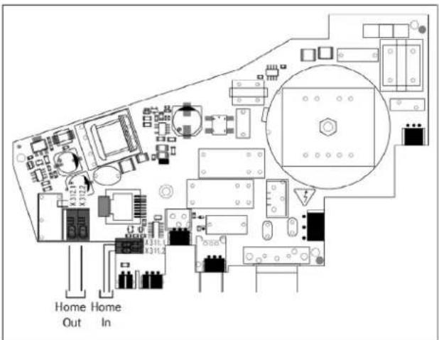
Fig. 4.64 Connection diagram for the external switch contacts
▶ Remove the snap-out element required for the cable feed from the plastic housing of the control unit.
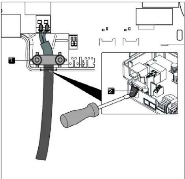
Fig. 4.65 Home Out contacts with strain relief
[1] Strain relief clamp
[2] Snap-out element for cable feed
▶ Clamp the connection cable in the strain relief clamp provided in accordance with the wire cross section or number of cables used.
▶ Check the correct installation, as well as the firm positioning of the connection cables.
▶ Close and secure the control unit cover.
▶ Screw down the lid with the screw provided (max. 2 Nm).
▶ Make sure that the cable is not damaged or trapped.
If the Home-In interface is connected to PKAS3/PKAS3AB, the two insulated wires of the connection cable must be joined together with a cable tie.

Fig. 4.66 PKAS3 Home-In interface cable tie
[1] Cable tie
[2] Home-In interface PKAS3/PKAS3AB
[3] Insulated wire

Fig. 4.67 Home Out contacts with strain relief
[1] Strain relief clamp
[2] Snap-out element for cable feed

Fig. 4.68 Fitting the strain relief clamp
[1] Strain relief clamp
4.13 Establishing communication and power connection
- The plug for the mains supply cable must be accessible following installation.
- If the mains supply cable has been damaged this must be replaced.
- The appliance components are linked by the ribbon cable provided.
4.13.1 Connecting the control knobs
Control knobs must only be connected to the ports provided on the appliance.
▶ Connect the control knobs to the appliances.

Fig. 4.69 Back of control knob with port
[1] Port on the back of the control knob
Connecting the control knobs to the cooktop extractor
▶ Connect the port on the back of the control knob to the port provided on the side of the cooktop extractor.

Fig. 4.70 Ports on the side of the cooktop extractor
[1] Control knob port
Connecting the control knobs to the cooktop
In the normal set-up the ports are on the front of the cooktops. According to the default settings, the left control knob operates the front cooking zone (zone 1) and the right control knob operates the rear cooking zone (zone 2).
Connect the port on the back of the left control knob to the "zone 2" port on the cooktop.
Connect the port on the back of the right control knob to the "zone 1" port on the cooktop.
▶ Using the configuration menu, set the correct allocation of the cooking zones in the control knob display (see "Configuration menu" in the operating instructions).
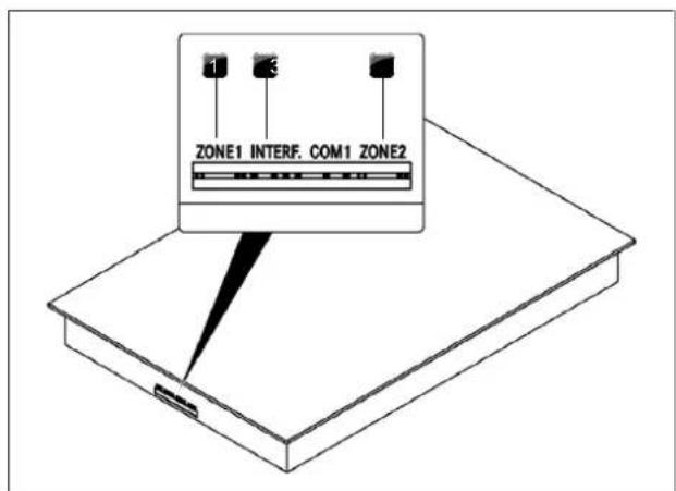
Fig. 4.71 Ports on the cooktop
[1] Front cooking zone control knob port (zone 1)
[2] Extractor electronics interface port
[3] Rear cooking zone control knob port (zone 2)

Fig. 4.72 Standard connection of appliances that connect at the front
[1] Cooktop
[2] Rear cooking zone (zone 2)
[3] Front cooking zone (zone 1)
[4] Rear cooking zone control knob (zone 2)
[5] Front cooking zone control knob (zone 1)

Fig. 4.73 Connecting the cooking zones when the cooktop is installed rotated by 180° and the ports are on the front of the appliance
[1] Cooktop
[2] Rear cooking zone (zone 1)
[3] Front cooking zone (zone 2)
[4] Rear cooking zone control knob (zone 1)
[5] Front cooking zone control knob (zone 2)

Fig. 4.74 Standard connection of appliances that connect at the front (PKG3)
[1] Cooktop
[2] Rear cooking zone (zone 1)
[3] Front cooking zone (zone 2)
[4] Rear cooking zone control knob (zone 1)
[5] Front cooking zone control knob (zone 2)

Fig. 4.75 Connecting the cooking zones when the cooktop is installed rotated by 180° and the ports are on the front of the appliance (PKG3)
[1] Cooktop
[2] Rear cooking zone (zone 2)
[3] Front cooking zone (zone 1)
[4] Rear cooking zone control knob (zone 2)
[5] Front cooking zone control knob (zone 1)
Connecting the control knob on the Tepan stainless steel grill
In the standard set-up the ports are on the back of the Tepan stainless steel grill PKT3.
In the case of the built-in version of the PKT3 installed rotated by 180°, excess cable must be reeled up in meander form and secured with cable ties.
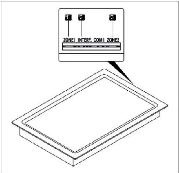
Fig. 4.76 Control knob port at the rear of the cooktop
[1] Front cooking zone control knob port (zone 1)
[2] Extractor electronics interface port
[3] Rear cooking zone control knob port (zone 2)

Fig. 4.77 Standard connection of appliances that connect at the rear (PKT3)
[1] Cooktop
[2] Rear cooking zone (zone 2)
[3] Front cooking zone (zone 1)
[4] Rear cooking zone control knob (zone 2)
[5] Front cooking zone control knob (zone 1)

Fig. 4.78 Connecting the cooking zones when the cooktop is installed rotated by 180° and the ports are on the rear of the appliance (PKT3)
[1] Cooktop
[2] Rear cooking zone (zone 1)
[3] Front cooking zone (zone 2)
[4] Rear cooking zone control knob (zone 1)
[5] Front cooking zone control knob (zone 2)
Special instructions for the wok cooktop PKIW3
As the wok cooktop PKIW3 only has one cooking zone, in the case of a connection with 2 control knobs it does not matter how the connections are arranged (see the operating instructions).
If the wok cooktop PKIW3 is installed with 2 control knobs, it can be operated with either the left or the right control knob.
Connecting the cooking zone in the case of 1 control knob
▶ Solely connect the port on the back of the control knob to the zone 1 port on the cooktop.
Connecting the cooking zone in the case of 2 control knobs
▶ Connect the ports on the back of the control knob to the ports on the cooktop (zone 1 or zone 2).
4.13.2 Ports on cooktop extractor system PKAS3

Fig. 4.79 Rear ports on PKAS3
[1] Home In
[2] Home In
[3] Additional fan control line
[4] Additional fan power supply cable
[5] Power supply cable with microfuse
Connecting an additional fan
▶ Connect the additional fan control line to the port provided on the back of the appliance.
▶ Connect the additional fan power supply cable to the port provided on the back of the appliance.
▶ Check all the plug connections to ensure that they are secure.
4.13.3 Connecting cooktop extractor PKA3
Connecting the control unit and fan to the cooktop extractor
▶ Using the CAT 5e communication cable (included in the scope of delivery) connect the port on the side of the cooktop extractor to the port on the control unit.
▶ Connect the plinth fan control line to the control unit.
▶ Connect the plinth fan power supply cable to the control unit.

Fig. 4.80 Side port for the control unit on cooktop extractor PKA3
[1] Control unit port
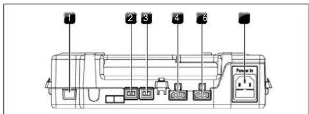
Fig. 4.81 Control unit ports
[1] CAT 5e communication cable socket
[2] Control unit socket for fan 2
[3] Control unit socket for fan 1
[4] Mains cable socket for fan 2
[5] Mains cable socket for fan 1
[6] Mains cable socket with micro fuse
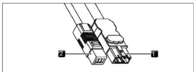
Fig. 4.82 Plinth fan connection plugs
[1] Fan mains cable connection plug
[2] Fan control cable connection plug
Removing the power supply cable
To remove the power supply cable from the control unit you need a small slotted screwdriver.
▶ Disconnect the control unit power supply cable from the power supply.
▶ Make sure that there is no power to the appliance.
▶ Use the slotted screwdriver to undo the lock on the fan power supply cable plug.
▶ To do this, insert the slotted screwdriver into the gap in the socket.
▶ Press the lock down gently.
▶ Use the slotted screwdriver to gently lever the power supply cable plug out of the control unit socket.
▶ Now disconnect the power supply cable from the socket.
▶ Check the plug and the socket for damage.
▶ Do not use damaged components.
▶ Contact your specialist BORA retailer to replace any damaged components.
Connecting an additional fan
▶ Connect the fan control line to the control unit.
▶ Connect the fan power supply cable to the control unit.
▶ Check all the plug connections to ensure that they are secure
4.13.4 Establishing contact between the cooktop extractor and cooktops
The full range of functions on the appliances will only be available if the cooktop extractor and cooktops are connected correctly.
▶ Using the communication ports provided, connect the cooktop extractor to the cooktop or cooktops.
▶ Only use the cables supplied in the scope of delivery.

Fig. 4.83 Communication between the cooktop extractor and cooktops
[1] Cooktop extractor communication cable port for left cooktop
[2] Cooktop extractor communication cable port for right cooktop
[3] Cooktop communication cable port
[4] Cooktop-to-cooktop-extractor communication cable
4.13.5 Connecting the power supply
Assembly, installation and commissioning must always occur in line with national laws, regulations and standards. The work must be performed by qualified specialists who know and comply with the additional regulations of the local energy supply companies.
Make sure that technical equipment is provided to enable all of the appliance's poles to be disconnected from the mains with a contact opening width of at least 3 mm (circuit breaker and automatic circuit breakers, fuses, contactor).
Connection diagrams
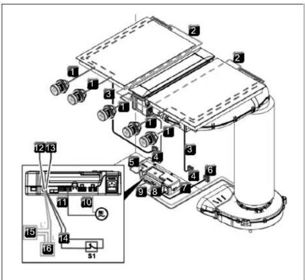
Fig. 4.84 PKA3 connection diagram
[1] Interface/control knob cable
[2] Cooktop communication cable
[3] Cooktop power supply cable
[4] Power supply for each cooktop
[5] CAT 5e communication cable
[6] Control unit power supply
[7] Control unit power supply cable (country-specific)
[8] Fan 1 power supply cable
[9] Fan 1 control line
[10] Fan 2 power supply cable
[11] Fan 2 control line
[12] Home Out port
[13] Home In port
[14] Home In connection cable
[15] External device
[16] Power supply for external device
[M] Fan 2
[S1] External switch contact
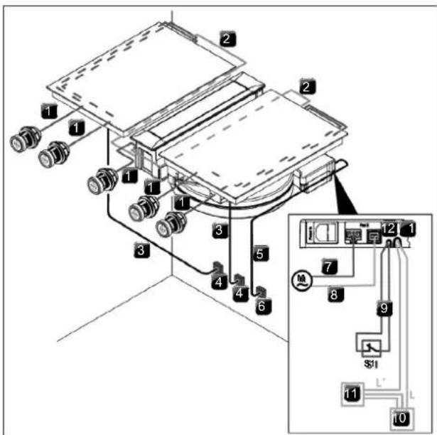
Fig. 4.85 PKAS3 connection diagram
[1] Interface/control knob cable
[2] Cooktop communication cable
[3] Cooktop power supply cable
[4] Power supply for each cooktop
[5] PKAS3/PKAS3AB power supply cable (country-specific)
[6] PKAS3/PKAS3AB power supply
[7] Fan 2 power supply cable
[8] Fan 2 control line
[9] Home In connection cable
[10] Power supply for external device
[11] External device
[12] Home In port
[13] Home Out port
[M] Fan 2
[S1] External switch contact
Special information for the Tepan stainless steel grill
The Tepan stainless steel grill is intended to be operated on a supply network with a maximum impedance Zmax at the transfer point (mains connection) of 0.0595 ohms. The user is to ensure that the appliance is only operated on a mains supply network which meets this requirement. If necessary, ask the local energy supply company about the system impedance.
Connecting the cooktop extractor to the power supply
Connect the extractor system (PKAS3) power supply cable and the control unit (PKA3) power supply cable respectively to the power supply.
▶ Put the cooktop extractor into operation (see the operating instructions).
▶ Check that all the functions are working correctly.
Connecting the cooktop to the power supply
The power supply cable to be used (already pre-installed) must comply with certain appliance-specific requirements.
A damaged power supply cable must be replaced by a suitable power supply cable. This may only be done by an authorised member of the After Sales Service team.
Power supply cable specifications and single-phase connection diagram for PKFI3, PKI3, PKIW3, PKG3
| Connection Fuse protection Wire cross section | Power supply cable | |
| 1-phase connection | 1 x 16 A 1.5 mm2 Type H05VVH2-F | |
Tab. 4.13 Fuse protection and minimum cross-section

Fig. 4.86 1-phase connection diagram
Power supply cable specifications and two-phase connection diagram for PKC3, PKCB3, PKCH3, PKT3
| Connection Fuse protection Wire cross section | Power supply cable | |
| 1-phase connection | 1 x 25 A 2.5 mm 2 Type H05V2V2-F | |
| 2-phase connection | 2 x 16 A 2.5 mm 2 Type H05V2V2-F | |
Tab. 4.14 Fuse protection and minimum cross-section
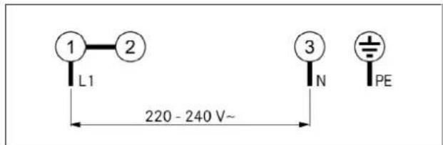
Fig. 4.87 1-phase connection diagram

Fig. 4.88 2-phase connection diagram
Connecting the cooktop to the mains
▶ Switch off the main switch/automatic circuit breaker before connecting the cooktop.
▶ Secure the main switch/automatic circuit breaker against being switched back on without permission.
▶ Make sure the power to the appliance is disconnected.
▶ Only connect the cooktop using a permanent connection to a power supply cable.
▶ Check that installation has been carried out correctly.
▶ Switch on the main switch/automatic circuit breaker.
▶ Put the cooktop into operation (see the operating instructions).
▶ Check that all the functions are working correctly.
4.14 Basic configuration
When installation is complete, you must carry out the basic settings (these settings can be changed at any time later on). You can see precise instructions on the basic configuration and all necessary information in the operating instructions.
4.14.1 Gas configuration
The burner nozzles, gas type and pressure may only be changed by a certified engineer or BORA service technician. They also assume responsibility for the proper gas installation and commissioning.
Gas characteristic curve A must not be used in the case of liquid gas (G30/31).
It is important that the gas type, gas pressure and characteristic curve are set correctly to ensure safe, failure-free operation of the gas cooktop.
You can see detailed information on the configuration menu in the operating instructions.
4.15 Initial operation
▶ Ensure that all appliances are connected correctly and connected to the power supply (fused) prior to initial operation.
- Exception: during initial operation, the kitchen fitter may use a temporary power supply for the control unit in order to configure the appliance (e.g. using the site power supply during the building phase).
- The settings made are saved and will not be affected when the system is disconnected from the mains.
- The final mains connection to the appliances may only be set up by certified specialists.
▶ Carry out a thorough function test on all appliances.
In the event of error messages, see the "Troubleshooting" chapter.
4.15.1 Using the gas cooktop for the first time
Initial operation is possible when the gas cooktop has been fully installed and configured.
Function test on the gas cooktop
▶ Switch the cooking zone on. The electronic gas regulator will calibrate itself (humming noises) and then the gas flame will automatically ignite in the selected cooking zone. The gas flame will burn steadily and evenly.
Using the gas cooktop together with the cooktop extractor for the first time
▶ Switch the cooktop extractor to the maximum power level.
▶ Switch all cooking zones to the minimum power level.
The electronic gas regulator will calibrate itself (humming noises) and then the gas flame will automatically ignite in the selected cooking zone. The gas flame will burn steadily and evenly (no reignition). The gas flame will be slightly affected by the cooktop extractor (airflow) – this is normal.
▶ Carry out a thorough function test on all appliances.
In the event of error messages, see the "Troubleshooting" chapter.
4.16 Sealing the appliances
▶ Once all of the installation work and initial operation is complete, seal the appliances all the way round (also between the cooktop extractor and cooktop) with black, heat-resistant silicone sealant.
▶ Make sure that no silicone sealant gets under the cooktop.

Fig. 4.89 Silicone sealant for flush installation
[1] Black, heat-resistant silicone sealant
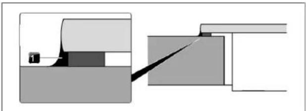
Fig. 4.90 Silicone sealant for surface mounting
[1] Black, heat-resistant silicone sealant
4.17 Handover to user
Once installation is complete:
Explain the main functions to the user.
Explain all safety-related aspects of operation and handling to the user.
▶ Provide the user with the accessories and operating and installation instructions, which are to be kept in a safe place.
▶ Affix the identification plates provided to the penultimate page in the operating instructions.
If a gas cooktop is installed:
▶ also affix the nozzle set identification plate to the penultimate page of the gas cooktop operating instructions.
5 Decommissioning, disassembly and disposal
▶ Observe all safety and warning information (see "2 Safety").
▶ Follow the enclosed manufacturer's information.
5.1 Decommissioning
Decommissioning refers to ultimate decommissioning and disassembly. Following decommissioning, the appliance can either be installed in another unit, sold on privately or disposed of.
The electricity and gas connections may only be disconnected and cut off by certified specialists.
▶ Switch the appliance off before decommissioning (see operating instructions)
▶ Disconnect the appliance from the power supply.
▶ Disconnect the appliance from the gas supply.
5.2 Disassembly
To be removed, the appliance must be accessible for disassembly and disconnected from the power supply.
In the case of gas appliances, it must be ensured that the gas is disconnected.
▶ Remove the appliance fastenings.
▶ Remove the silicone seals.
▶ Disconnect the appliance from the exhaust duct.
▶ Lift the appliance up and out through the top of the worktop.
▶ Remove any other accessories.
▶ Dispose of the old appliance and any soiled accessories as described under “Environmentally-friendly disposal”.
5.3 Environmentally-friendly disposal
5.3.1 Disposal of transport packaging
The packaging protects the appliance from damage during transport. The packaging materials have been selected taking into account the environment and their disposal and are therefore recyclable.
Recycling the packaging saves raw materials and reduces waste. Your specialist retailer will take the packaging back.
▶ Give the packaging to your specialist retailer
or
▶ dispose of the packaging correctly observing regional regulations.
5.3.2 Disposal of accessories
Dispose of unnecessary or used accessories (activated charcoal filters, etc.) accordingly taking into account the regional regulations.
5.3.3 Disposal of the old appliance

Electrical appliances with this mark must not be disposed of in the household waste at the end of their service life. They must be disposed of at a collection point for the recycling of electrical or electronic appliances. Information on this can be obtained from the city or local councils.

Waste electrical and electronic appliances often still contain valuable materials. However, they also contain harmful substances that were necessary to make them work and ensure their safety. If placed in the household waste or handled incorrectly, they may harm human health and damage the environment.
▶ Never dispose of your old appliance in the household waste.
▶ Take the appliance to a regional collection point for the return and further processing of electrical and electronic components and other materials.
Notes
| . | |||||||||||||||||||||||||||||
| . | |||||||||||||||||||||||||||||
| . | |||||||||||||||||||||||||||||
| . | |||||||||||||||||||||||||||||
| 0.0000000000000000000000000000000000000000000000000000000000000000000000000000000000000000000000000000 | |||||||||||||||||||||||||||||
| . . . . . . . . . . . . . . . . . . 123.4.15.16.17.18.19.21.22.23.24.25.26.27.28.29.31.32.33.34.35.36.37.38.39.41.42.43.44.45.46.47.48.49.51.52.53.54.55.56.57.58.59.61.62.63.64.65.66.67.68.69.71.72.73.74.75.76.77.78.79.81.82.83.84.85.86.87.88.89.91.92.93.94.95.96.97.98.99.111(1)(2)(3)(4)(5)(6)(7)(8)(9)(11)(12)(13)(14)(15)(16)(17)(18)(19)(21)(22)(23)(24)(25)(26)(27)(28)(29)(31)(32)(33)(34)(35)(36)(37)(38)(39)(41)(42)(43)(44)(45)(46)(47)(48)(49)(51)(52)(53)(54)(55)(56)(57)(58)(59)(61)(62)(63)(64)(65)(66)(67)(68)(69)(71)(72)(73)(74)(75)(76)(77)(78)(79)(81)(82)(83)(84)(85)(86)(87)(88)(89) (8:11) (8:12) (8:13) (8:14) (8:15) (8:16) (8:17) (8:18) (8:19) (8:20) (8:21) (8:22) (8:23) (8:24) (8:25) (8:26) (8:27) (8:28) (8:29) (8:30) (8:31) (8:32) (8:33) (8:34) (8:35) (8:36) (8:37) (8:38) (8:39) (8:40) (8:41) (8:42) (8:43) (8:44) (8:45) (8:46) (8:47) (8:48) (8:49) (8:50) (8:51) (8:52) (8:53) (8:54) (8:55) (8:56) (8:57) (8:58) (8:59) (8:60) (8:61) (8:62) (8:63) (8:64) (8:65) (8:66) (8:67) (8:68) (8:69) (8:70) (8:71) (8:72) (8:73) (8:74) (8:75) (8:76) (8:77) (8:78) (8:79) (8:80) (8:81) (8:82) (8:83) (8:84) (8:85) (8:86) (8:87) ( ) ① ② ③ ④ ⑤ ⑥ ⑦ ⑧ ⑨ ⑩ ⑪ ⑫ ⑬ ⑭ ⑮ ⑯ ⑰ ⑱ ⑲ ⑳ ⑴ ⑵ ⑶ ⑷ ⑧ ⑨ ⑩ ⑪ ⑫ ⑬ ⑭ ⑮ ⑯ ⑰ ⑱ ⑲ ⑳ ⑴ ⑤ ⑥ ⑦ ⑧ ⑨ ⑩ ⑪ ⑫ ⑬ ⑭ ⑮ ⑯ ⑰ ⑱ ⑲ ⑳ ⑴ ⑤ ⑥ ⑦ ⑧ ⑨ ⑩ ⑪ ⑫ ⑬ ⑭ ⑮ ⑯ ⑰ ⑱ ⑲ ⑳ ㉑ ㉒ ㉓ ㉔ ㉕ ㉖ ㉗ ㉘ ㉙ ㉚ ㉛ ㉜ ㉝ ㉞ ㉟ ㉟ ㉟ ㉟ ㉟ ㉟ ㉟ ㉟ ㉟ ㉟ ㉟ ㉟ ㉟ ㉟ ㉟,㉟,㉟,㉟,㉟,㉟,㉟,㉟,㉟,㉟,㉟,㉟,㉟,㉟,㉟,㉟,㉟,㉟,㉟,㉟,㉟,㉟,㉟,㉟,㉟,㉟,㉟,㉟,㉟,㉟,㉟,㉟,㉟,㉟, θ , θ , θ , θ , θ , θ , θ , θ , θ , θ , θ , θ , θ , θ , θ , θ , θ , θ , θ , θ , θ , θ , θ , θ , θ , θ , θ , θ , θ , θ , θ , θ , θ , θ , 双面的平方程是完全二次方程是完全二次方程是完全二次方程是完全二次方程是完全二次方程是完全二次方程是完全二次方程是完全二次方程是完全二次方程是完全二次方程是完全二次方程是完全二次方程是完全二次方程是完全二次方程是完全二次方程是完全二次方程是完全二次方程是完全二次方程是完全二次方程是完全二次方程是完全二次 方程是完全二次方程是完全二次方程是完全二次方程是完全二次方程是完全二次方程是完全二次方程是完全二次方程是完全二次方程是完全二次方程是完全二次方程是完全二次方程是完全二次方程是完全二次方程是完全二次方程是完全二次方程是完全二次方程是完全二次方程是完全二次方程是完全二次方程是完全二次方向程是完全二次方向程是完全二次方向程是完全二次方向程是完全二次方向程是完全二次方向程是完全二次方向程是完全二次方向程是完全二次方向程是完全二次方向程是完全二次方向程是完全二次方向程是完全二次方向程是完全二次方向程是完全二次方向程是完全二次方向程是完全二次方向程是完全二次方向程是完全二次方向程是完全二次方向程是完全二次向程是完全二次方向程是完全二次方向程是完全二次方向程是完全二次方向程是完全二次方向程是完全二次方向程是完全二次方向程是完全二次方向程是完全二次方向程是完全二次方向程是完全二次方向程是完全二次方向程是完全二次方向程是完全二次方向程是完全二次方向程是完全二次方向程是完全二次方向程是完全二次方向程是完全二次方向程是完全二次方程是完全二次方向程是完全二次方向程是完全二次方向程是完全二次方向程是完全二次方向程是完全二次方向程是完全二次方向程是完全二次方向程是完全二次方向程是完全二次方向程是完全二次方向程是完全二次方向程是完全二次方向程是完全二次方向程是完全二次方向程是完全二次方向程是完全二次方向程是完全二次方向程是完全二次向线段段段段段段段段段段段段段段段段段段段段段段段段段段段段段段段段段段段段段段段段段段段段段段段段段段段段段段段段段段段段段段段段段段段段段段段段段段段段段段段段段段段段段段段段段段段段段段段段段段段段 | |||||||||||||||||||||||||||||
Installation instructions: ○Original ⊙Translation
The distribution and duplication of this document, as well as the use and disclosure of its contents are prohibited unless expressly authorised. Great care was taken when devising these operating and installation instructions. However, it may be the case that later technical changes have not yet been added or the corresponding contents have not yet been modified. We apologise for this. An up-to-date version can be requested from the BORA Service team. Misprints and errors excepted.
info@boraapac.com.au
bora-australia.com.au

+800 7890 0987

(01)04251731212057(240)004563-10001


- EN INSTALLATION INSTRUCTIONS PROFESSIONAL
- CONTENTS
- GENERAL INFORMATION
- SAFETY
- TECHNICAL DATA
- INSTALLATION
- DECOMMISSIONING, DISASSEMBLY AND DISPOSAL
- VALIDITY OF THE OPERATING AND INSTALLATION INSTRUCTIONS
- LIABILITY
- PRODUCT CONFORMITY
- DIRECTIVES
- REGULATIONS
- DATA PRIVACY
- PRESENTATION OF INFORMATION
- SAFETY AND WARNING INSTRUCTIONS
- DANGER
- TYPE AND SOURCE OF DANGER
- FIGURES
- INTENDED USE
- GENERAL SAFETY INSTRUCTIONS
- WARNING
- CAUTION
- RISK OF INJURY FROM HEAVY LIFTING
- DAMAGE FROM IMPROPER USE
- PLEASE NOTE
- FAULTS AND ERRORS
- SAFETY INFORMATION FOR INSTALLATION
- RISK OF INJURY FROM INCORRECT ASSEMBLY
- RISK OF ELECTRIC SHOCK FROM DAMAGED APPLIANCE
- RISK OF ELECTRIC SHOCK FROM INCORRECT STRIPPING OF CABLES
- SAFETY INSTRUCTIONS – COOKTOP EXTRACTOR INSTALLATION
- SAFETY INFORMATION FOR COOKTOP INSTALLATION
- SAFETY INSTRUCTIONS – REPAIRS, SERVICING AND SPARE PARTS
- SAFETY INSTRUCTIONS – DISASSEMBLY AND DISPOSAL
- COOKTOP EXTRACTOR PKA3/PKA3AB
- COOKTOP EXTRACTOR SYSTEM WITH INTEGRATED FAN PKAS3/PKAS3AB
- SURFACE INDUCTION COOKTOP PKFI
- INDUCTION COOKTOP PKI
- INDUCTION WOK COOKTOP PKIW
- HILIGHT COOKTOP, 3-RING/2-RING PKC
- HILIGHT COOKTOP, 3-RING/ROASTER PKCB
- HYPER COOKTOP, 1-RING/2-RING PKCH
- TEPAN STAINLESS STEEL GRILL PKT
- GAS COOKTOP PKG
- CONTROL KNOB
- GENERAL INSTALLATION INSTRUCTIONS
- GENERAL INSTALLATION INSTRUCTIONS FOR COOKTOPS
- ADDITIONAL INSTALLATION INSTRUCTIONS FOR AUSTRALIA AND NEW ZEALAND (AU/NZ)
- RESTRICTED FUNCTIONS WHEN USING THE COOKTOPS WITHOUT A COOKTOP EXTRACTOR
- OPERATING THE COOKTOP EXTRACTOR IN THE EXHAUST AIR MODE AND WHERE THERE IS A FIREPLACE DEPENDENT UPON THE AIR SUPPLY IN THE ROOM
- CHECKING THE SCOPE OF DELIVERY
- SCOPE OF DELIVERY OF THE COOKTOP EXTRACTOR
- SCOPE OF DELIVERY OF THE COOKTOPS
- TOOLS AND AIDS
- ASSEMBLY INSTRUCTIONS
- INSTALLATION CLEARANCES
- MINIMUM INSTALLATION DIMENSIONS
- WORKTOP
- KITCHEN UNITS
- SPECIAL ASSEMBLY INSTRUCTIONS FOR THE GAS COOKTOP
- POSITIONING OF THE GAS COOKTOP WITH TWO COOKTOP EXTRACTORS
- AIR SUPPLY FOR THE GAS COOKTOP
- RETURN FLOW OF RECIRCULATED AIR
- CUT-OUT DIMENSIONS
- WORKTOP OVERHANG
- FLUSH INSTALLATION
- SURFACE MOUNTING
- CONTROL KNOB INSTALLATION
- COOKTOP EXTRACTOR BORE HOLES
- COOKTOP BORE HOLES
- FITTING THE CONTROL KNOB
- PLANNING VARIATIONS FOR PKA3/PKA3AB
- AIRFLOW STRAIGHT TO THE SIDE
- AIRFLOW TOWARDS THE LEFT
- ROTATING THE COVER FRAME BY 180°
- INSTALLING THE COOKTOP EXTRACTOR
- FITTING THE COOKTOP EXTRACTOR
- SECURING THE COOKTOP EXTRACTOR
- PREPARING THE MOUNTING BRACKETS
- INSTALLING THE DUCT SYSTEM
- DUCT CONNECTION DIMENSIONS
- PREPARING FOR INSTALLATION
- CONNECTING THE DUCT SYSTEM TO THE APPLIANCE
- STANDARD SET-UP FOR PKA3/PKA3AB
- POSITIONING THE CONTROL UNIT
- INSTALLING THE ADDITIONAL FAN
- GAS INSTALLATION
- VENTILATION
- GAS CONNECTION
- CONNECTING THE GAS SUPPLY
- NATURAL GAS (NG)
- LIQUIFIED PETROLEUM GAS (LPG)
- WHEN SWITCHING FROM NG TO ULPG, THE STICKER PROVIDED MUST BE AFFIXED
- CHANGING THE GAS TYPE
- CHANGING THE GAS BURNER NOZZLE IN THE GAS BURNER
- AFFIXING THE NOZZLE SET NAMEPLATES
- INSTALLING THE COOKTOPS
- PREPARING THE COOKTOP EXTRACTOR WHEN USING THE WOK COOKTOP
- INSTALLING THE COOKTOP
- INSTALLING THE TEPAN STAINLESS STEEL GRILL
- COOKTOP INSTALLATION ROTATED BY 180°
- INSTALLATION ROTATED BY 180°
- GAS COOKTOP INSTALLATION ROTATED BY 180°
- TEPAN STAINLESS STEEL GRILL INSTALLATION ROTATED BY 180°
- CONNECTING EXTERNAL SWITCH CONTACTS
- PREPARING PKAS3/PKAS3AB
- PREPARING THE CONTROL UNIT ON PKA3/PKA3AB
- PREPARING CONNECTION CABLES FOR EXTERNAL SWITCHING EQUIPMENT
- CONTACT CONNECTION CABLE
- TAB. 4.12 CONNECTION CABLE
- PKA3/PKA3AB
- PKAS3/PKAS3AB
- INSTALLING THE EXTERNAL SWITCH DEVICE
- ESTABLISHING COMMUNICATION AND POWER CONNECTION
- CONNECTING THE CONTROL KNOBS
- CONNECTING THE CONTROL KNOBS TO THE COOKTOP EXTRACTOR
- CONNECTING THE CONTROL KNOBS TO THE COOKTOP
- CONNECTING THE CONTROL KNOB ON THE TEPAN STAINLESS STEEL GRILL
- SPECIAL INSTRUCTIONS FOR THE WOK COOKTOP PKIW
- PORTS ON COOKTOP EXTRACTOR SYSTEM PKAS
- CONNECTING AN ADDITIONAL FAN
- CONNECTING COOKTOP EXTRACTOR PKA
- CONNECTING THE CONTROL UNIT AND FAN TO THE COOKTOP EXTRACTOR
- REMOVING THE POWER SUPPLY CABLE
- ESTABLISHING CONTACT BETWEEN THE COOKTOP EXTRACTOR AND COOKTOPS
- CONNECTING THE POWER SUPPLY
- SPECIAL INFORMATION FOR THE TEPAN STAINLESS STEEL GRILL
- CONNECTING THE COOKTOP EXTRACTOR TO THE POWER SUPPLY
- CONNECTING THE COOKTOP TO THE POWER SUPPLY
- CONNECTING THE COOKTOP TO THE MAINS
- BASIC CONFIGURATION
- GAS CONFIGURATION
- INITIAL OPERATION
- USING THE GAS COOKTOP FOR THE FIRST TIME
- FUNCTION TEST ON THE GAS COOKTOP
- USING THE GAS COOKTOP TOGETHER WITH THE COOKTOP EXTRACTOR FOR THE FIRST TIME
- SEALING THE APPLIANCES
- HANDOVER TO USER
- ONCE INSTALLATION IS COMPLETE
- IF A GAS COOKTOP IS INSTALLED
- DECOMMISSIONING
- DISASSEMBLY
- ENVIRONMENTALLY-FRIENDLY DISPOSAL
- DISPOSAL OF TRANSPORT PACKAGING
- DISPOSAL OF ACCESSORIES
- DISPOSAL OF THE OLD APPLIANCE
- NOTES
Brand : BORA
Model : Professional 3.0 system
Category : Cooker