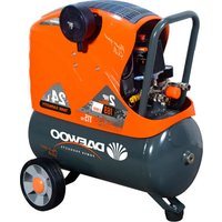
DAAC24DN - Compressor DAEWOO - Free user manual and instructions
Find the device manual for free DAAC24DN DAEWOO in PDF.


| Brand | Daewoo |
| Model | DAAC24DN |
| Product Type | Compressor |
| Tank Capacity | 24 liters |
| Max Pressure | 8 bar / 116 psi |
| Power Source | 230 V ~ 50 Hz |
| Motor Power | 1.5 kW (2 HP) |
| Air Output | 180 L/min |
| Noise Level | ~70 dB |
| Dimensions (L x W x H) | 40 x 30 x 50 cm |
| Weight | 15 kg |
| Oil-Free Pump | Yes |
| Pressure Gauge | Yes |
| Safety Valve | Yes |
| Regulator | Yes |
| Drain Valve | Yes |
| Portability | Handle and rubber feet |
| Maintenance | Drain water daily after use |
| Safety Features | Thermal overload protection |
| Application | Inflation, nailing, air tools |
Frequently Asked Questions - DAAC24DN DAEWOO
User questions about DAAC24DN DAEWOO
0 question about this device. Answer the ones you know or ask your own.
Ask a new question about this device
Download the instructions for your Compressor in PDF format for free! Find your manual DAAC24DN - DAEWOO and take your electronic device back in hand. On this page are published all the documents necessary for the use of your device. DAAC24DN by DAEWOO.
USER MANUAL DAAC24DN DAEWOO
USER'S MANUAL
www.daewoopowerproducts.com
Manufactured under license of Daewoo International Corporation, Korea
INDEX
- PREPARATION FOR STARTING 2
- SAFETY GUIDELINES .... 2
- WARNING ...... 2
- CAUTION 3
- APPLICATION 3
- GENERAL VIEW AND MAIN COMPONENTS 4
- TECHNICAL SPECIFICATIONS .... 5
- SPARE PARTS LIST 6
- THINGS TO DO THE FIRST TIME 8
- OPERATION AND MAINTENANCE ....11
- TROUBLES AND REMEDIES LIST OF GOODS ....12
WARRANTY....13
1. PREPARATION FOR STARTING
(1) Air compressor should be placed in a clean, dry and ventilated area.
(2) In order to extend compressor lifespan, reduce heat for moving parts by making sure this air compressor cover must be at least 0.3\~0.5 meters away from the wall.
(3) Keep voltage within±5% of rating
(4) Keep the oil level in the red circle leveler.
(5) Recommend compressor oil SAE30 or L-DAB 100 when temperature above 10° C, SAE10 or L-DAB68 when temperature below 10° C.
(6) The normal temperature of working environment should be -5°c 35°c , and the altitude of the working place should be 2000m below.
(7) The normal temperature of compressor body is 180° C and the lubricating oil in the crankcase is less than 70° C when the compressor is working.
(8) Open outlet valve and let air compressor compressor run 10 minutes without load before regular operation
2. SAFETY GUIDELINES
DANGER-AN IMMEDIATE HAZARD THAT WILL CAUSE SERIOUS INJURY OR LOSS OF LIFE
(1). To reduce the risk of fire or explosion, never spray flammable liquids in a confined area. It is normal pressure switch to produce sparks while operating. If sparks come into contact with vapors from gasoline or other solvents, they, may ignite causing fire or explosion, Always operate the compressor in a well-ventilated area, Do not smoke while spraying. Do not spray where sparks or flame are present, Keep compressor as far from spray area as possible.
(2). The solvents Trichloroethane and Methylene Chloride can chemically react with aluminum used in paint spray guns, paint pumps, etc, and cause an explosion. If you are using these solvents, use only stainless steel spray equipment, This does not affect your air compressor, but many affect the equipment being used.
(3). Never directly use the compressed air produced by a compressor. It is not suitable for breathing purposes.
3. WARNING-A POTENTIAL HAZARD THAT COULD CAUSE SERIOUS INJURY OR LOSS OF LIFE.
(1). Do not weld on the air tank of this compressor. Welding on the air compressor tank strength and cause an extremely hazardous condition. Welding on the tank in any manner will void the warranty
(2). Never use an electric air compressor outdoors when it is raining or on a wet surface, as it many cause an electric shock.
(3). This unit starts automatically. Always shut off the compressor, remove the plug from the outlet, and emptying all pressure from the system before servicing the compressor, and when the compressor is not in use.
(4). Check the manufacture's maximum pressure rating for air tools and accessories. Compressor outlet pressure must be regulated so as to never exceed the maximum pressure rating of the tool.
(5).High temperatures and moving parts are present under the protection cover. To prevent burns or other injuries, Do not operate with the protection cover removed. Do not allow the compressor parts to cool before handling or servicing.
(6). Be certain to read all labels when you are spraying paints or toxic materials and follow the safety instructions. Use a respirator mask if there is a chance of inhaling anything you are spraying, Read all instructions and be sure that your respirator mask will protect you.
(7). Always wear safety goggles or glasses when using an air compressor. Never point any nozzle or sprayer toward a person or any part of the body.
(8). Do not adjust the pressure switch or relief valve for any reason, Doing so voids all warranties. They have been preset at the factory for the maximum pressure of this unit.
4. CAUTION-A POTENTIALL HAZARD THAT MAY CAUSE MODEFATE INJURY OR DAMAGE TO EQUIPMENT.
(1).Drain the moisture from the tank on a daily basis. A clean, dry tank will help prevent corrosion.
(2). Pull the pressure relief valve ring daily to ensure that the valve is functioning properly, and to clear the valve of any possible(bstructions.
(3). To provide proper ventilation for cooling, the compressor must be kept a minimum of 31cm(12 inches) form the nearest wall, in a well-ventilated area.
(4). Fasten the compressor down securely if transporting is necessary, Pressure must be released from the tank before transporting
(5). Protect the air hose and electric cord from damage and puncture. Inspect them weekly for weak or worn spots and replace if necessary.
5.APPLICATION
The compressors are widely used in various pneumatic tools and machine of communication, machinery manufacture, medical and health, garments, spinning and weaving works, such as tyre, gas-filled, painting etc.
- GENERAL VIEW AND MAIN COMPONENTS

- SWITCH
- SAFETY VALVE
- REGULATOR
- GAUGE
- OIL WINDOW
- AIR FILTER
- DRAIN COCK
- BREATH PIPE
7. TECHNICAL SPECIFICATIONS
DAAC24DN
Power: 2 hp/1.5 kW
Tank capacity: 24 L
Cylinders: 1*42 mm/1*47 mm
Air filter type: 3/8" Plastic
Pressure: 8 bar/115 psi
Engine speed: 2850 rpm(50 Hz)/
3450 rpm(60 Hz)
Flow: 135 L/min(1*42mm)/
169 L/min(1*47mm)
Noise: 84 dB
DAAC50DN
Power: 2hp/1.5 kW
Tank capacity: 50 L
Cylinders: 1*42 / 1*47 mm
Air filter type: 3/8" Plastic
Pressure: 8 bar/115 psi
Engine speed: 2850 rpm(50 Hz)/
3450 rpm(60 Hz)
Flow: 135 L/min(42 mm) 169 L/min(47 mm)
Noise: 89 dB

| NO | Name | Quinty | Uint | NO | Name | Quinty | Uint |
| 1 | Bolt | 4 | PCS | 37 | Bearing | 1 | PC |
| 2 | Cylinder head | 1 | PC | 38 | Rotor | 1 | PC |
| 3 | Air filter | 1 | PC | 39 | Bearing | 1 | PC |
| 4 | Exhaust elbow | 1 | PC | 40 | Rear motor cover | 1 | PC |
| 5 | Cylinder head gasket | 1 | PC | 41 | Spring washer | 4 | PCS |
| 6 | Bolt | 2 | PCS | 42 | Bolt | 4 | PCS |
| 7 | Lock washer | 2 | PCS | 43 | Fan | 1 | PC |
| 8 | Valve limiter | 1 | PC | 44 | Snap spring | 1 | PC |
| 9 | Valve reed | 1 | PC | 45 | Bolt | 6 | PCS |
| 10 | Valve plate | 1 | PC | 46 | Capacitor | 1 | PC |
| 11 | Valve plate gasket | 1 | PC | 47 | Protector | 1 | PC |
| 12 | Intake valve sheet | 1 | PC | 48 | Terminal cap | 4 | PCS |
| 13 | Position pin | 2 | PCS | 49 | Insulating sheath | 2 | PCS |
| 14 | Cylinder | 1 | PC | 50 | Exhaust pipe group | 1 | PC |
| 15 | Cylinder gasket | 1 | PC | 51 | Check valve | 1 | PC |
| 16 | Compression ring | 2 | PCS | 52 | Housing cover | 1 | PCS |
| 17 | Oil ring | 1 | PC | 53 | Housing bottom | 1 | PCS |
| 18 | Piston | 1 | PC | 54 | Check hole connector | 2 | PCS |
| 19 | Piston pin | 1 | PC | 55 | Tank | 1 | PC |
| 20 | Snap spring | 2 | PCS | 56 | Nut | 2 | PCS |
| 21 | Connecting rod | 1 | PC | 57 | Wheel | 2 | PCS |
| 22 | Breath pipe | 1 | PC | 58 | Plain washers | 2 | PCS |
| 23 | "O" Ring | 1 | PC | 59 | Axle | 2 | PCS |
| 24 | Bolt | 6 | PCS | 60 | Dain valve | 1 | PC |
| 25 | Oil leveler | 1 | PC | 61 | Nut | 1 | PC |
| 26 | Crankcase cover | 1 | PC | 62 | Foot pad | 1 | PC |
| 27 | Cover seal | 1 | PC | 63 | Bolt | 1 | PC |
| 28 | Bolt | 1 | PC | 64 | Power cord | 1 | PC |
| 29 | Crank | 1 | PC | 65 | Terminal | 6 | PCS |
| 30 | Crankcase | 1 | PC | 66 | Safety valve | 1 | PC |
| 31 | Bolt | 4 | PCS | 67 | Regulator valve | 1 | PC |
| 32 | Bolt | 4 | PCS | 68 | Release pipe | 1 | PC |
| 33 | Nut | 1 | PC | 69 | Pressure gauge | 2 | PCS |
| 34 | Stator | 4 | PCS | 70 | Quick connector | 2 | PCS |
| 35 | Cable | 1 | PC | 71 | Pressure switch | 1 | PC |
| 36 | Oil seal | 1 | PC |
9.THINGS TO DO FOR THE FIRST TIME
(1) Connect the wheel to the air compressor.

(2) Use screwdriver to tight the axle

(3) Install the Rubber foot pad to the air compressor.

(4) Remove the Warning Sign and oil plug

(5) Add the oil

Oil must be add until the red point

(6) Install the breath pipe into the hole of the crankcase cover
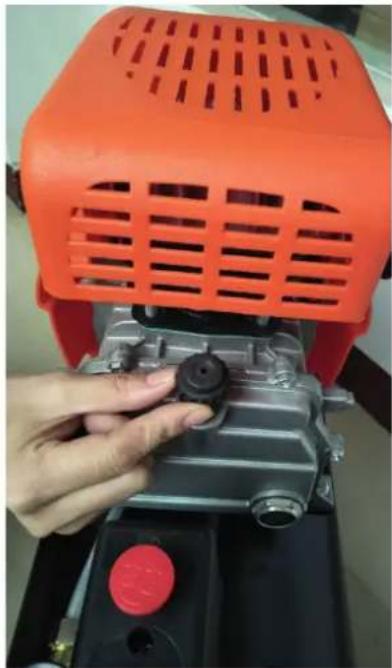
(7) Install the Air Filter into the compressor head.

(8) Connect the power
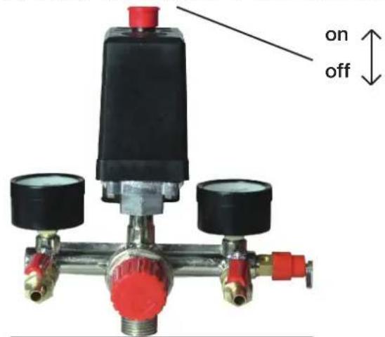
(9) Pull up the red knob of pressure switch in position on
(1). Please check the technical documents carefully after you opened the case(documents including introduction manual) Check if the spare parts are correct, and check if the compressor is in good condition.
(2). Pull out the oil plug, filling N32 machine lubricating oil to the oil hole till the stipulated level in winter. While in summer using N68 machine lubricating oil. Then insert breath pipe, Plug in the power cord and operate the compressor without load, check if it operates properly.
(3). Conneting to the pneumatic tools, starting the compressor, then you can use tools. Note: The compressor should be started without any working pressure.
(4). The compressor uses machine lubricating oil, Please filling oil before operating. During operation the oil, temperature must be below 70 (use N32 in winter and N68 in summer).
(5). After 500 hours operation, replace the oil, And disassemble crankcase end cover, clean the old oil and dirty things. Then reassemble the crankcase end cover, fill fresh oil.
(6).Usually clean air filter once a week.
(7). After operation 16 hours open drain valve under tank, drain the water from the tank, Clean tank once a half year.
(8)Clean crankcase every 120 working hours, and check safety valve and pressure gauge.
(9). After each use, turn off the power. drain all the pressure from the tank.
(10). Maintaining the compressor normally, Disassemble the compressor. Then using light oil, such as gasoline, clean all the parts, And drying them, during assembling, smear grease on the touching surfaces. If necessary repair or replace worn parts. Assemble and adjust the parts correctly. Note: Electric units should be grounded correctly.
(11). If the compressor stop using for a long period, air valves and touching surface should be cleaned and smeared with grease.
11. TROUBLES AND REMEDIES LIST OF GOODS
| PROBLEM | POSSIBLE CAUSE(S) | CORRECTIVE ACTION |
| Compressor will not run 1.No electrical power2.Blown fuse3.Breaker open4.Thermal overload opern5.Pressure switch bad | 1.Plugged in? Check fuse/breaker2.Replace blown fuse.3.Reset determining why problem Happened4.Motor will restart when cool (approx. 15minutes).5.Contact Authorized Service Center | |
| Motor hums but cannot run or runs slowly | 1.Low voltage2.Shorted or open motor winding3.Defective check valve or pressure switch4.Compressed air in cylinder | 1.Check with voltmeter(105v.min)2.Contact Authorized Service Center3.Contact Authorized Service Center4.Turn the AUTO? OFF switch to the OFF position for 15 sec. then turn to the AUTO position |
| Fuses blow/circuit breaker trips repeatedlyCAUTION!!NEVER USE AN EXTENSIONCORD WITH THIS PRODUCT! | 1.Incorrect size fuse circuit overloaded2.Defective check valve or pressure switch | 1.Check for proper fuse. Use timedelay fuse. Disconnect from other electrical appliances from circuit or operate compressor on its own branch circuit2.Contact Authorized Service Center |
| Thermal overload protector Cuts out repeatedly | 1.Low voltage2.Clogged air filter3.Lack of proper ventilation/room temperature too high | 1.Check with voltmeter(105v.min)2.Clean filter(see Maintenance section).3.Move compressor to well ventilated area. |
| Tank pressure drops when compressor shuts off | 1.Loose connections(fittings tubing, etc)2.Open draincock.3.Check valve leaking | 1.Check for air leaks. Use sealing tape on all leaking connections.2.Tighten draincock.3.Disassemble check valve assembly.Clean or replace.DANGER!!DO NOT DISASSEMBLE CHECKVALVE WITH AIR IN TANK BLEED TANK FIRST |
| Excessive moisture in discharge air | 1.Excessive water in tank2.High humidity3.Clogged intake filter | 1.Drain receiver2.Move compressor to area of less humidity: use air line filter3.Clean or replace filter |
| Compressor runs continually | 1.Defective pressure switch2.Excessive air usage | 1.Replace switch2.Compressor not large enough to meet CFM requirement or the air tool |
| Compressor vibrates. 1.Loose mounting bolts2.Rubber tank feel worn/missing | 1.Tighten2.Replace | |
| Air output lower than normal | 1.Open draincock2.Intake filter dirty3.Connection leaking | 1.Tighten draincock2.Clean or replace intake filter3.Tighten connections |
WARRANTY CARD
![graph TD A[" "] --> B["Product model"] B --> C["Serial number"] C --> D["Username"] D --> E["Client's signature"] F[" "] --> G["Date of sale"] H[" "] --> I["Company"]](/content/2026/07/1497856/images/b5e6ea8a3c1a4cfaefe71feee649e3dba207a38991d15ba4e6209c5288344d7f.jpg)
The product is in good conditions and fully complete. Read and agree the terms of the warranty.
GUARANTEE
The warranty period starts from the date of sale of the products and covers 2 years for all power products.
During the warranty period, free failures caused due to the use of poor-quality materials in the production and manufacturer workmanship admitted fault are removed. The guarantee comes into force only when warranty card and cutting coupons are properly filled. The product is accepted for repair in its pure form and full completeness.
WARRANTY DOES NOT COVER
- Mechanical damage (cracks, chips, etc.) and damage caused by exposure to aggressive media, foreign objects inside the unit and air vents, as well as for damage occurred as a result of improper storage (corrosion of metal parts);
- Failures caused by overloading or product misuse, use of the product for other purposes. A sure sign of overload products is melting or discoloration of parts due to the high temperature, simultaneous failure of two or more nodes, teaser on the surfaces of the cylinder and the piston or destruction of piston rings. Also, the warranty does not cover failure of the automatic voltage regulator due to incorrect operation;
- Failure caused by clogging of the fuel and cooling systems;
- Wearing parts (carbon brushes, belts, rubber seals, oil seals, shock absorbers, springs, clutches, spark plugs,
mufflers, nozzles, pulleys, guide rollers, cables, recoil starter, chucks, collets, removable batteries, filters and safety elements, grease, removable devices, equipment, knives, drills, etc.);
• Electrical cables with mechanical and thermal damage;
- Product opened or repaired by a non-authorized service center.
- Prevention, care products (cleaning, washing, lubrication, etc.), installation and configuration of the product;
• Natural wear products (production share);
- Failures caused by using the product for the needs related to business activities;
- If the warranty card is empty or missing seal (stamp) of the Seller;
- The absence of the holder's signature on the warranty card.


DAEWOO
POWER PRODUCTS


- INDEX
- PREPARATION FOR STARTING
- SAFETY GUIDELINES
- WARNING-A POTENTIAL HAZARD THAT COULD CAUSE SERIOUS INJURY OR LOSS OF LIFE
- CAUTION-A POTENTIALL HAZARD THAT MAY CAUSE MODEFATE INJURY OR DAMAGE TO EQUIPMENT
- 5.APPLICATION
- TECHNICAL SPECIFICATIONS
- DAAC24DN
- DAAC50DN
- 9.THINGS TO DO FOR THE FIRST TIME
- TROUBLES AND REMEDIES LIST OF GOODS
- WARRANTY CARD
- GUARANTEE
- WARRANTY DOES NOT COVER
- DAEWOO
- POWER PRODUCTS
Brand : DAEWOO
Model : DAAC24DN
Category : Compressor