R32 YC42T1 - Air Conditioning Yamato - Free user manual and instructions
Find the device manual for free R32 YC42T1 Yamato in PDF.


| Product Type | Split Air Conditioner |
| Model | R32 YC42T1 |
| Brand | Yamato |
| Refrigerant | R32 |
| Cooling Capacity | 12000 BTU/h |
| Heating Capacity | 13000 BTU/h |
| Energy Efficiency Ratio (EER) | 3.5 |
| Power Supply | 220-240V ~ 50Hz |
| Indoor Unit Dimensions (WxHxD) | 800 x 290 x 210 mm |
| Outdoor Unit Dimensions (WxHxD) | 700 x 550 x 250 mm |
| Indoor Unit Weight | 10 kg |
| Outdoor Unit Weight | 25 kg |
| Airflow Rate (Indoor) | 420 m³/h |
| Noise Level (Indoor) | 28-40 dB(A) |
| Timer Function | Yes, 24-hour programmable |
| Sleep Mode | Yes |
| Filter Type | Washable pre-filter |
| Maintenance | Clean filter every 2 weeks |
| Safety Features | Auto restart, overheat protection |
| Spare Parts Availability | Remote control, filters available |
| Warranty | 2 years |
Frequently Asked Questions - R32 YC42T1 Yamato
User questions about R32 YC42T1 Yamato
0 question about this device. Answer the ones you know or ask your own.
Ask a new question about this device
Download the instructions for your Air Conditioning in PDF format for free! Find your manual R32 YC42T1 - Yamato and take your electronic device back in hand. On this page are published all the documents necessary for the use of your device. R32 YC42T1 by Yamato.
USER MANUAL R32 YC42T1 Yamato
YC12T1/I, YC12T1/O, YC12T1/P YC18T1/I, YC18T1/O, YC18T1/P YC24T1/I, YC24T1/O, YC24T1/P YC42T1/I, YC42T1/O, YC42T1/P YC48T1T/I, YC48T1T/O, YC48T1T/P YC55T1T/I, YC55T1T/O, YC55T1T/P
This instruction manual contains important information and recommendations that we would ask you to comply with to obtain best results from air conditioner.
Thank you once again.
Safety Notice
 | The air conditioner is charged with inflammable refrigerant R32. |
 | Before using the air conditioner, please first read the instruction manual. |
 | Before installing the air conditioner, please first read the instruction manual. |
 | Before repairing the air conditioner, please first read the technical service manual. |
Compared with common refrigerant, R32 is an environmental-friendly refrigerant that has no harm to the ozone layer and weak greenhouse effect. Its GWP is 675. Because of its thermodynamic characteristics, R32 requires a smaller charging quantity to reach high energy efficiency. It is inflammable and odourless, but may cause explosion under certain circumstances.
CONTENTS
PRECAUTION 01
PARTS AND FUNCTIONS 03
FUNCTION AND OPERATION OF PANEL'S PARTS 04
DISPLAY PANEL
INDOOR UNIT INSTALLATION 06
INSTALLATION OF PANEL 13
FIGURE OF BODY SIZE 15
OUTDOOR UNIT INSTALLATION 16
REFRIGERANT PIPE INSTALLATION 18
ELECTRIC WIRING 21
ADJUSTING AIR FLOW DIRECTION 26
IMPORTANT SAFETY INFORMATION 27
TROUBLESHOOTING 29
REFRIGERANT NOTICE/CONCENTRATION 32
PRECAUTION
- Read the following " PRECAUTIONS" carefully before installation.
- The caution items stated here must be followed because these important contents to safety. The meaning of each indication used is as below.
Incorrect installation due to ignoring of the instruction will cause harm or damage, seriousness is classified by the following indications.
 WARNING WARNING | This indication shows the possibility of causing death or serious injury. |
| [γXAG] CAUTION | This indication shows the possibility of causing injury or damage to properties only. |
NOTE :
- Injury means causing harmed, burned, electrical shocked, but not serious for hosp
- Damage of property means disrepair of property, material.
- Carry out test running to confirm that no abnormality occurs after the installation. ain to user the operation, care and maintenance as stated in instructions. Please customer to keep the operating instructions for future reference.
 WARNING WARNING |
| ● Engage dealer or specialist for installation. If installation done by user is will cause water leakage, electrical shock or fire. |
| ● Install according to this installation instructions strictly. If installation is defec cause water leakage, electrical shock or fire. |
| ● Use the attached accessories parts and specified parts for installation. Othe cause the set to fall, water leakage, fire or electrical shock. |
| ● Install at a strong and firm location which is able to withstand the set's gth is not enough or installation is not properly done, the set will drop |
| ● For electrical work, follow the local national wiring standard, regulation and tion instructions. An independent circuit and single outlet must be used. If capacity is not enough or defect found in electrical work, it will cause e |
| ● When carrying out piping connection, take care not to let air or other su than the specified refrigerant go into refrigeration cycle. Otherwise, it will o capacity, abnormal high pressure in the refrigeration cycle, explosion and in |
| ● Grounding is necessary. It may cause electrical shock if grounding is not |
| ● Do not install the unit at place where leakage of flammable gas may oo leaks and accumulates at surrounding of the unit, it may cause fire. |
Operating condition
The protective device maybe trip and stop the unit within temp range listed below:
| HEATING | Outdoor air temperature is over 24°C |
| Outdoor air temperature is below -15°C | |
| Room temperature is over 27°C | |
| COOLING | Outdoor air temperature is over 50°C |
| Outdoor air temperature is below -15°C | |
| Room temperature is below 17°C | |
| DRY | Room temperature is below 17°C |
If the air conditioner runs for a long time in "COOLING" or "DRY" mode at air relative humidity higher than 80% (doors or windows opened), dew may generate and drip near air outlet.
Noise pollution
- Install the air conditioner in a place that can bear its weight in order to operate more quietly.
- Install the outdoor unit in a place where the air discharged and the operation noise do not annoy your neighbors.
- Do not place any obstacles in front of the outlet of the outdoor unit for fear it affects operation and increases the noise level.
Features of Protector
① The protective device will trip at following cases.
- Stop the appliance and restart it at once or change other modes during operation, you have to wait 3 minutes before restarting.
- After switching on the power circuit breaker and then turn on the air conditioner at once, you have to wait about 20 seconds.
② In case all operations have stopped, you need
- Press "ON/OFF" button again to restart it.
- Set TIMER once again if it has been canceled.
Inspection
After a long time of operation, the air conditioner should be inspected for the following items.
• Abnormal heating of the power supply cord and plug or even a burnt smell.
• Abnormal operating noise or vibration.
• Water leakage from indoor unit.
• Metal cabinet electrified.
Stop using the air conditioner if above problem happened. It is advisable that the air conditioner should be given a detail check-up after using for five years even if none of the above happen.
Features of HEATING mode
Preheat
2-5 minutes are necessary to preheat the indoor heat exchanger at the beginning of "HEATING" operation, lest cold air be discharged.
Defrost
In "HEATING" operation the appliance will defrost automatically. This procedure lasts 2\~10 minutes, then returns to "HEATING" mode automatically. During defrosting, indo fan stop running and return to heating mode operation automatically when defrosting has finished.
PARTS AND FUNCTIONS

① Air Outlet
② Wire controller
③ PUMP
④ Drainage Pipe
⑤ Air Return
⑥ Filter
⑦ Remote controller
⑧ AIR FLOW LOUVER
⑨ Refrigerant connection pipe
⑩ Connecting cord
⑪ Cut-off valve
⑫ Air Outlet grille
Requirements
- The air conditioner cannot be started up until it is powered on for 2 hour. Furthermore, in case of a shutdown lasting for about one diel only, please do off the electricity supply. (it is necessary to heat the crankcase heater so as force start of compressor.)
- Notice that the air inlet/outlet must not be choked up. If chokeup air conditioner behavior may be affected, or air conditioner cannot run because actuation of protector.

NOTICE
Please adjust room temperature properly especially when the old men, children, patients stay at house.
Lightning and other electromagnetic radiation may cause ill effect. If it is, please plug off the power switch, and replug in, then restart the unit.
Do not block the inlet of indoor unit or outlet of outdoor unit, any of blocks will reduce cooling or heating efficiency.
CONSTITUTION OF PANEL
- It suits for Body dimension: 840X245X840 or 840X290X840 cooling and heating pump type.

1.PANEL
2.AIR FLOW LOUVER
3.INFRARED SIGNAL RECEIVER
4.DISPLAY PANEL
5.AIR-Return GRILLE
- It suits for Body dimension :580X255X580 cooling and heating pump type.

1.PANEL
2.AIR FLOW LOUVER
3.INFRARED SIGNAL RECEIVER
4.DISPLAY PANEL
5.AIR-Return GRILLE
DISPLAY PANEL
Infrared signal receiver: receive the signal from the remote controller.
To make your remote controller operation more efficient, please let remote controller emitt or aim at infrared signal receiver.
Buzzer: firstly power supplied or any of remote controller operations will make the buzzer sound once.
Some obstacles occurring in the system will be recognized by intelligent recognition system of unit ,lighting on the DISPLAY PANEL flashing show the type of obstacles
◇ DISPLAY PANEL
- It suits for Body dimension :840X245X840 or 840X290X840 cooling and heating pump
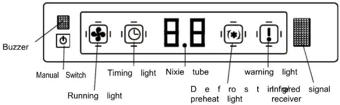
- It suits for Body dimension :580X255X580 cooling and heating pump type.

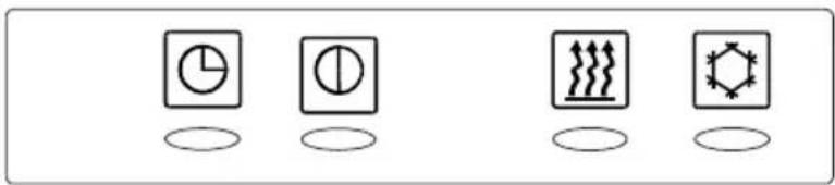
INFRARED SIGNAL RECEIVER

Timer indicator ON when preset time for switching ON/OFF the unit
Operation indicator ☐: ON when the unit is power on
PRE-DEF indicator ON when the unit prevent cool a ir flowing in room.
Pump indicator ON when the water level is high
INDOOR UNIT INSTALLATION
(Please select the space to install indoor unit according to the dimension show above, then install correctly, and have enough space for maintenance.
Select installation location considering piping and wiring connection after the Indoor Ur been hanged. Then decide the piping wiring leading direction.
- Be sure to lead the refrigerant pipes, drain pipes and connection wires out to its location before hanging the unit if the opening on the ceiling has been decided.
- Confirm sizes of the indoor unit and ceiling opening with the attached installation pattern. (Please fix the paper pattern below the body with M5X16 screws (4).
Unit: mm
| A | H | |
| 12/18K | 245 | 130~135 |
| 24K | 245 | 130~135 |
| 30 K | 245 | 130~135 |
| 36K | 290 | 175~180 |
| 42K | 290 | 175~180 |
| 48K | 290 | 175~180 |
| 55K | 290 | 175~180 |

INSTALLATION LOCATIONS

CAUTIONS
- Location in the following places may cause malfunction of the machine. (If unavoid please consult your local dealer)
a. A place where there is flammable gas leakage.
b. There is salty air surrounding(near the coast).
c. There is caustic gas(the sulfide, for example) existing in the air (near a hot sp
d. A place where can not bear the weight of the machine.
e. In kitchen where it is full of oil gas
f. There is strong electromagnetic wave existing.
g. There is acid or alkaline liquid evaporating.
h. A place where air circulation is not enough.
I. The appliance shall not be installed in the laundry
- Electrical Insulation must be done on the air conditioner and the building comply National Regulations.
INSTALLATION SPACE

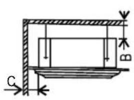
| Wall material | Flammable material | Fire-proof material or other nonflammable materials other than metal | Fire-proof structure |
| Up(B) | Above 5cm | Above 5cm | Above 5cm |
| Sides(C) | Above 100cm | Above 100cm | —— |
■ HEIGHT BETWEEN CEILING AND FLOOR
The installation height between ceiling and floor must be 2.7m\~3.2m.
■ CEILING HOLE AND THE HOOK INSTALLATION
Preparation Work on the Ceiling
● Installation method should be changed under the different construction structure. Please consult the professional for the detailed information.
● After opening a hole, the ceiling should be horizontal and strong to prevent vibration.
① Cut the beams at the hole and remove them.
② Reinforcing the beams that have been cut and the beams fixing the ceiling.
Installation of the hanging screw bolt
Bolt with M10 whorl is to be used. The center distance between the bolts is decided by the size of the unit. Use the following method to install:
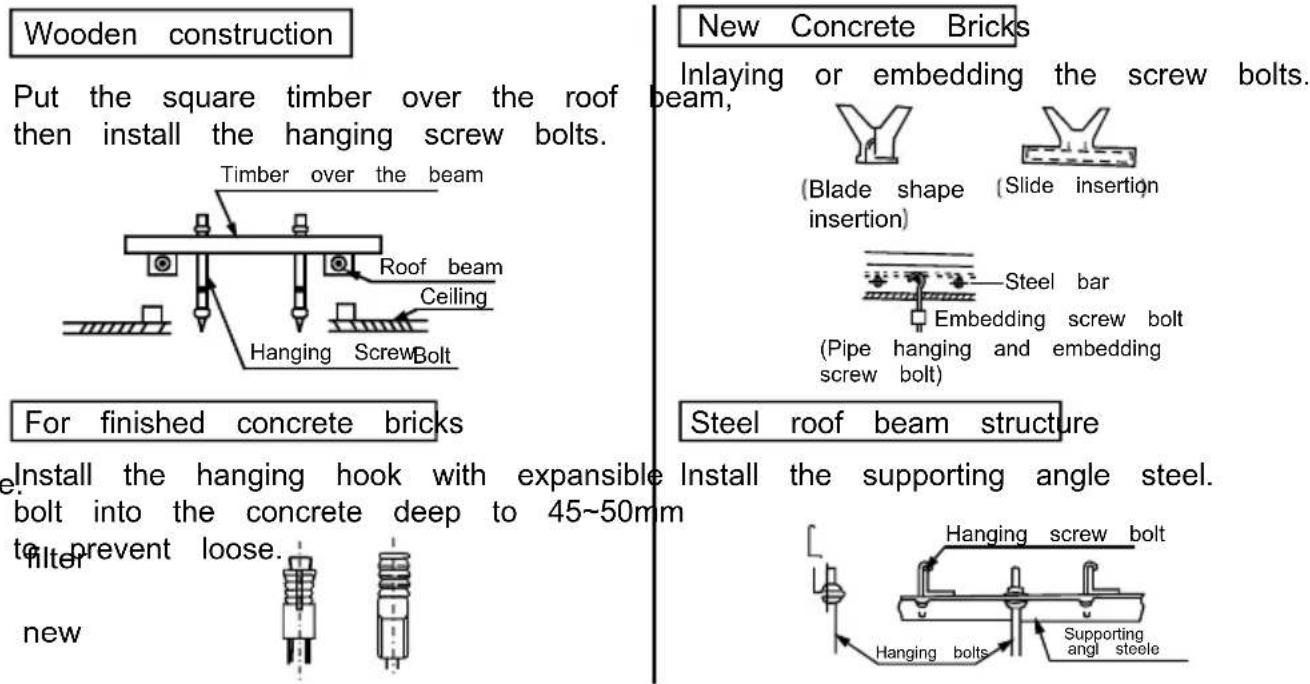
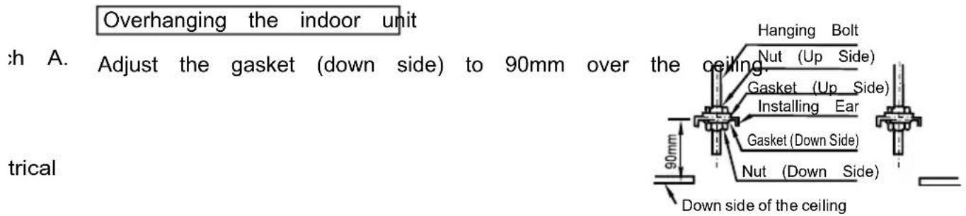
- Install the hanging bolt into T groove of the hanging tool. Overhang the indoor unit and ensure it is level using a level indicator.

air filter.If the in it and
PANEL INSTALLATION
- Panel installation should be done after piping and wiring.
- Be sure that the indoor unit and ceiling hole installation size is right before installatic
CAUTION
Be sure to seal the connection parts between the andelining panel - the indoor unit ,or even small gaps may cause wind/water leakage or condensing water.
DRAINAGE PIPE INSTALLATION
CAUTION
Be sure to follow Installation Manual during drainage installation, the drainage pipe must have the heat insulation to prevent condensing.
CAUTION
- The drain pipe of indoor unit must have the heat insulation, or it will condense d connections of the indoor unit.
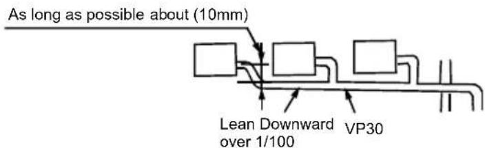
● The declivity of the drain pipe downwards should be over 2/100, and no winding and
● The total length of the drain pipe when pulled out traversely shall not exceed 20m pipe is over long, a prop stand must be installed every 1.5 to 2m to prevent wind - Refer to the following figures about the installation of the pipes.
- Do not impose any pressure on the connection part of the drainage pipe.

Drainage Pipe Material, Heat-insulating Material
The listed material should be used:
| Drainage Pipe Material | Polyvinyl chloride pipe (32mm outer diameter) |
| Heat Insulation Material | Foamed polyethylene insulation plate (10mm thickness) |
Flexible Hose
Measure diameter of the hard pipe using cutting method, and adjust the joining ang
efrost
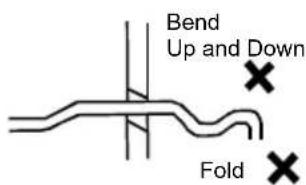
- Pull out the flexible hose, do not over deform than illustrated below.
is
- Be sure to bind it with the attached band.
- Please place the flexible hose horizontally.
details. cting.

Connection Procedure
Connect the transparent pipe with the polyvinyl chloride pipe.
- Use polyvinyl chloride glue at the connection part of the drainage pipe, be sure leakage.
- Paste glue at the front 40mm of the polyvinyl chloride pipe, insert it into the trace - It needs 10 minutes for the glue to dry. Do not impose pressure on the connected drying period.
Heat Insulation
Wrap the flexible hose carefully with the attached heat insulation material from the start to the end (to indoor part)
vation

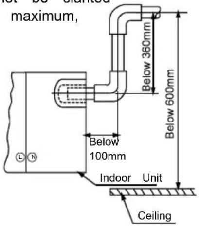
Drainage Upward
To make sure that the drainage pipe would not be slanted
downward, lead it upward to a height 360mm maximum, then downward lead it.
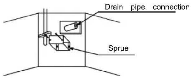
Drainage Test
- Check whether the drain pipe is unhindered before testing.
1) Stow water from sprue to check.
2) Stow 600cc water with pot or hose from sprue slowly , preventing touching the drain |
3) After the preparation work, disconnect the water level switch, power 220-240V to AC of terminal board, and the drain pump start up immediately.
4) After drain pump run 2 min., reset the water level pin, and the drain pump motor will running 22min..
Motor Sound Test
• The drainage test is doing during checking the drain pump motor running sound .
- Reset the water level switch connection to the original position after the drainage te
INSTALLATION OF PANEL

BODY DIMENSION:
Unload air-in grille
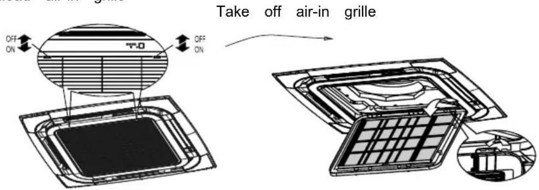
Unload panel installation cap

cracking.
INSTALLATION OF PANEL
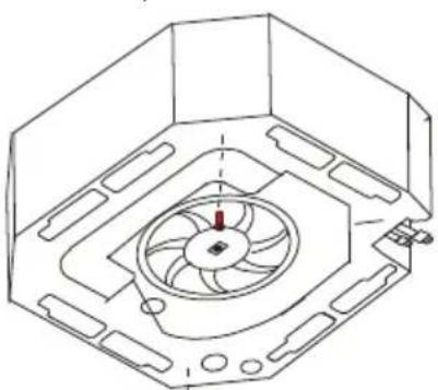
- Please screw M10 gasket and M6*20 bolt at the corner of indoor unit,
before screwing them fasten,screw other two
additional bolt swhich locatesred bolt showin
gas figure and notice that the direction
of red arrow on theelectrical box
aligns the one on the panel.
- Please connect step motor wire, display board wire to
the electrical box according to ELECTRIC WIRING
DIAGRAM on theelectrical box.
- Then screw the other two M6*20 bolt with M10
gasket through the hole of panel into outdoor unit.
frigerant
- Adjust the location and direction of panel to tally
louver of panel with outlet of outdo screw
all the bolts fasten to make the panel and
outdoor unit pressed together.
3
- Return the air-in grille and panel back to the
outdoor unit.


BODY DIMENSION:580X255X580
Unload air-in grille
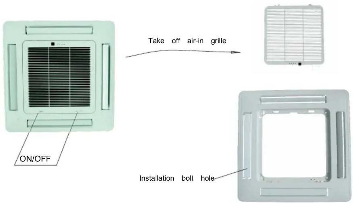

INSTALL ATION OF PANEL
-
Please screw M10 gasket and M6*20 bolt at the corner of indoor unit, before screwing them fasten, screw other two additional bolts which locates red bolt showing as figure and notice that the direction of red arrow on the electrical box aligns the one on the panel.
-
Please connect step motor wire, display board wire to the electrical box according to ELECTRIC WIRING DIAGRAM on the electrical box.
-
Then screw the other two M6*20 bolt with M10 gasket through the hole of panel into outdoor unit.
-
Adjust the location and direction of panel to tally louver of panel with outlet of outdoor, screw all the bolts fasten to make the panel and outdoor unit pressed together.
-
Return the air-in grille and panel back to the outdoor unit.


Figure of body size
Split type outdoor unit
Unit: mm
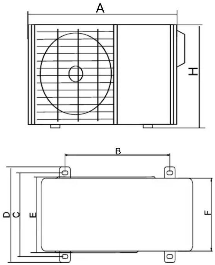
| MODE | A | B | C | D | E | F | H |
| 12/18K | 780 | 516 | 314 | 350 | 321 | 307 | 605 |
| 24K | 845 | 574 | 348 | 375 | 358 | 342 | 700 |
| 30K | 845 | 574 | 348 | 375 | 358 | 342 | 700 |
| 36K | 910 | 607 | 390 | 421 | 391 | 378 | 804 |
| 42K | 910 | 607 | 390 | 421 | 391 | 378 | 804 |
| 48K | 1010 | 660 | 462 | 494 | 440 | 436 | 858 |
| 55K | 1010 | 660 | 462 | 494 | 440 | 436 | 858 |
IS.
OUTDOOR UNIT INSTALLATION
Move outdoor unit in
- Please use 4 pieces of 6mm steel wire hanging the outdoor unit up and move in.
- To avoid the outdoor unit is out of shpe, please add the baffles at the surface of outdoor unit where the steel wire ropemay touch.
- after moving, please remove the tray wood on the bottom.

INSTALLATION SPACE
- After leaving repair space as illustrated below, install the outdoor unit with power supply equipment installed at the side of the outdoor unit. Please refer to ELECTRIC SUPPLY INSTALLATION MANUAL for the installation method.
- Please make sure necessary space for installation and repair.

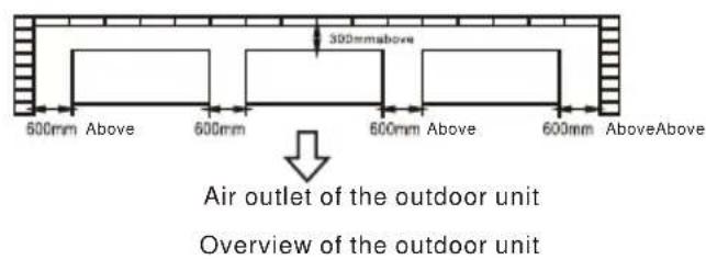

No obstruction from the air outlet of outdoor unit
- At least 600mm space must be left between outdoor units as the sketch indicated.

Refrigerant pipe
- The junction is inside the cover of the right panel, please take off the cover first.
- The pipe gets out of the side gap of the cover.
- After connecting from the valve gap, reinstall it from left, right or backwards for installation.
- The right picture is the sketch map of valve installation board of outdoor. Gas-side(low pressure) is the one upward, liquid side is the one downward.

INSTALLATION
Pre-installation precautions
- Please confirm that the installation personnel are qualified in relevant installation service. If the air conditioner was installed by persons without special skills, normal operations would not be ensured, even the personal and estate safety would be affected.
User guideline
■ The user's installation site should be provided with regular power supply in conformity with that indicated in nameplate of the air conditioner, and its voltage should be within a range 90%\~110% of the rated voltage value.
■ Power circuit should be equipped with protector, such as electricity leakage protector or air switch, which should possess a capacity greater than 1.5 times the maximum current value of the air conditioner.
■ Never fail to adopt personal circuit and effectively-grounded socket compatible with the attached plug of the air conditioner. The attached plug is equipped with grounding pin, and it must not be modified as desired.
■ Please adopt the fuse or circuit breaker prescribed in Installation Instructions.
■ Only qualified electrician is allowed to carry out wiring tasks strictly according to electric safety requirements.
■ Do ensure good earth of air conditioner, in other words, the main power switch of air conditioner must be connected to reliable ground wire.
Precautions
■ The air conditioner should be installed securely; otherwise poor installation may lead to abnormal noises and vibration.
■ Outdoor unit should be installed at a spot ensuring that its air outlet noises and hot exhaust will not violate your neighbors.
Unit body installation
Please confirm the indoor unit dimension according to the picture below M10 whorl is to be installed.(4 sets)
◆please refer to the following for the center distance between the bolts
◆M 10 whorl is used
◆please consult professional for your specific ceiling arrangement.
- Dismantle scale of the ceiling.....please keep ceiling its level. Strengthen the beam to avoid vibration.
-
Break the beam of the ceiling
-
Strengthen the breaking point of the ceiling and reinforce the ceiling beam.
After the main body hanging is finished, arrangement of pipe and line will be done in the ceiling. The direction of the pipe is determined after the installation location is chosen. If the ceiling has existed, please arrange the refrigerant pipe, drainage pipe, indoor and outdoor connecting line.
◆ Installation of the hanging screw bolt
REFRIGERANT PIPE INSTALLATION
Pipe dimension and ways of installation
Outdoor pipe dimension and ways of install (in sequence of cooling capacity
| Copper Pipe for Air ConditionerPipe | ||||
| Model | 12/18K | 24K | 30/36/42/48/55K | |
| Size(mm) | Liquid side | φ 6.35(7/16inch) | φ 6.35(7/16inch) | φ 9.52(5/8inch) |
| Gas side | φ 9.52(5/8inch) | φ 12.7(3/4inch) | φ 15.88(7/8inch) | |
| Conventional pipe, cooling capacity18000~30000Btu/h | Allowed value | |
| Longest pipe(L) | 30m | |
| Maximum height drop | Height drop between indoor and outdoor unit H | 15m |
| Conventional pipe, cooling capacity36000~42000Btu/h | Allowed value | |
| Longest pipe (L) | 50m | |
| Maximum height drop | Height drop between indoor and outdoor unit H | 25m |
| Conventional pipe, cooling capacity48000~55000Btu/h | Allowed value | |
| Longest pipe (L) | 60m | |
| Maximum height drop | Height drop between indoor and outdoor unit H | 30m |
Please refer to refrigerant pipe connection for detail.
Allowed length and height drop
Remove objects and water

- Use high-pressure nitrogen to clean the pipe instead of outdoor refrigerant.
● Before instal ling refrigerant pipe, please clean the pipe in case of foreign objects.
Additional refrigerant charge
The additional charge is base on the diameter and length of outlet/inlet liquid type. This AC has been charged with that for 5m pipe, those beyond 5 m should recharge as follow
| Liquid pipe diameter | 1/4 | 3/8 | 1/2 |
| Additional charge for 1m pipe(R32) | 0.016kg | 0.040kg | 0.096Kg |
FIARING
① Cut the refrigerant pipr off with pipe cutter.

② Flaring after putting the pipe into connection
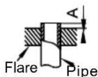
| Outside Diameter | A (mm) | |
| MAX | MIN | |
| φ 1/4'' | 8.7 | 8.3 |
| φ 3/8'' | 12.4 | 12.0 |
| φ 1/2'' | 15.8 | 15.4 |
| φ 5/8'' | 19.0 | 18.6 |
| φ 3/4'' | 23.3 | 22.9 |
Stop valve operation item
- Open the valve rod til to the position rod.
Do not trey to open larger. - Fasten the bonnet with spanner or similar tools.
- Fasten the bonnet of valve rod.
Liquid side( φ3/8,φ1/2 ): 1180N·cm(120kgf·cm)
gas side( φ5/8'' , φ3/4'' ): 1180N·cm(120kgf·cm)
Junction fixture
- Aim at connection pipe fix the nut of connection pipe, then tighten] as the following diagram with spanner
Notice
- According to installation conditions, overlarge wrenched torch will destroy the nut. (Unit. N.cm)
| Outside diameter | Steng then t of fasten the torch |
| φ 1/4'' | 1420~1720N cm(144~176kgf .cm) |
| φ 3/8'' | 3270~3990N cm(333~407kgf .cm) |
| φ 1/2'' | 4950~6030N cm(504~616kgf .cm) |
| φ 5/8'' | 6180~7540N cm(630~770kgf .cm) |
| φ 3/4'' | 9720~11860N cm(990~1210kgf .cm) |

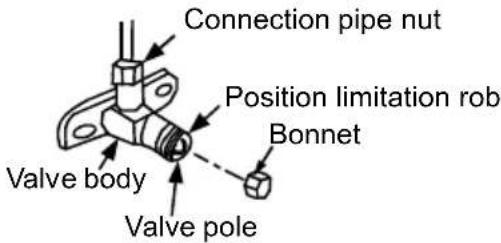
■ When vacuum pump is used, each low-pressure valve muse be manipulated as follow. Please refer to operation manual for the usage of manifold valve.
- Connect the recharged hose to lower pressure valve junction (low/high pressure valve must tightened.)
- Connect the charged hose junction with vacuum pump.
- Open the low pressure handler of manifold fully.
- Start vacuumizing with vacuum pump. Wjhen vacuumizing begins, loosen the nut of low pres: valve a bit. Check is the air enters (noise of vacuum pump changes, the all-purpose meter changefrom negative to zero), then tighten the nut of connection pipe.
- After vacuumizing finishing, tighten the low pressure Multi-function gauge | pressure gauge
handler of manifoldvalve fully and stops the vacuum pump.
When vacuumizing is carried out for over 15 minutes, please confirm if the all-purpose meter points at -1.0X10
Pa(-76cmHg)。
6.Open the high/low pressure valve fully.
7. Dismantle the recharged hose from charge gap of low pressure valve. Low presa
8. Tighten the bonnet of low-pressure valve.
Low pressure valve
High pressure valve

- The following figure only shows the assembly relationship of the indoor unit, outdoor unit and refrigerant pipes.
- Please refer to the following figures to install.
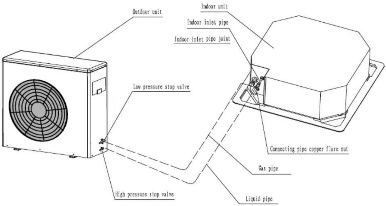
NOTE
- The throttle subassemhas been installed in the outdoor unit..
- Use two spanners to connect the pipe with indoor/outdoor pipes to avoid the copper p
- Please pay attention to the connection orientation when connecting.
AIR PURGING
Use a vacuum pump, to vacuum from the gas side refrigerant adding mouth of the outunit.
Air and moisture remains inside the refrigeration system, may has the following bad effect
- Rise of pressure inside the refrigeration system;
• Decrease of cooling (or *heating) effect; - Moisture frozen and blocking the refrigeration system;
• Rusting of certain parts of the system
- Don’t use the refrigerant of the outdoor unit to do the vacuum. (A certain volume of had been added into the outdoor unit in factory.)
After connecting the indoor and outdoor units, it is necessary to exhaust the air inside pipes completely as follows:
ELECTRIC WIRING
! WARNING
Specified power cables should be used. Do not apply any pressure on the terminals used to connect.
Improper connection may cause fire.

Grounding must be properly done.
The grounding wire should be away from gas pipes, water pipes, telephonic lightening rods or other grounding wires. Improper grounding may cause electric shock.
Electric Wiring must be done by professionals. Use a separate circuit according to national regulations.

pump motor. terminal
stop after
The temperature of refrigerant circuit will be hight, please keep the interconnection away from the copper tube.
If the wiring capacity is not enough, electric shock or fire may occur.
If the supply cord is damaged, it must be replaced by the manufacturer or its s or a similarly qualified person in order to avoid a hazard
An all-pole disconnection switch having a contact separation of at least 3mm in auld beconnected in fixed wiring.
CAUTION
Be sure to Install Current Leakage Protection Switch. Or electric shock may the appliance must be positioned so that the plug is accessible
the appliance shall be installed in accordance with national wiring regulations
oc
CAUTION
● Power cord is to be selected according to national regulations.
- Outdoor unit power cord should be selected and connected according to the outdoor unit installation manual.
- Wiring should be away from high temperature components, or the insulation layer of the wires may melt down.
- Use wire clamp to fix the wires and terminal block after connection.
• Control wire should be wrapped together with heat insulated refrigerant pipes.
- Connect the indoor unit to power only after the refrigerant has been vacuumed.
- Don’t connect the power wire to the signal wire connection end.
Panel Wiring
Connect the Swing Motor terminal block according to cassette indoor unit wiring diagram.
Terminal Board Diagram
Please refer to cassette indoor unit wiring for the wiring.
■ Steps of external wiring connection
- Remove air intake grille and electric box cover of indoor unit.
- Remove access door of outdoor unit.
- Connect the power supply connecting cablethe control connecting cable and defrostconnecting cable between indoor and outdoor unit.Please refer to the following pages for details.
- Make sure the cables being fixed well with an effective anchorage after connected
- Grounding work must be carried out for indoor and outdoor units.
- Install the components removed back to the unit.
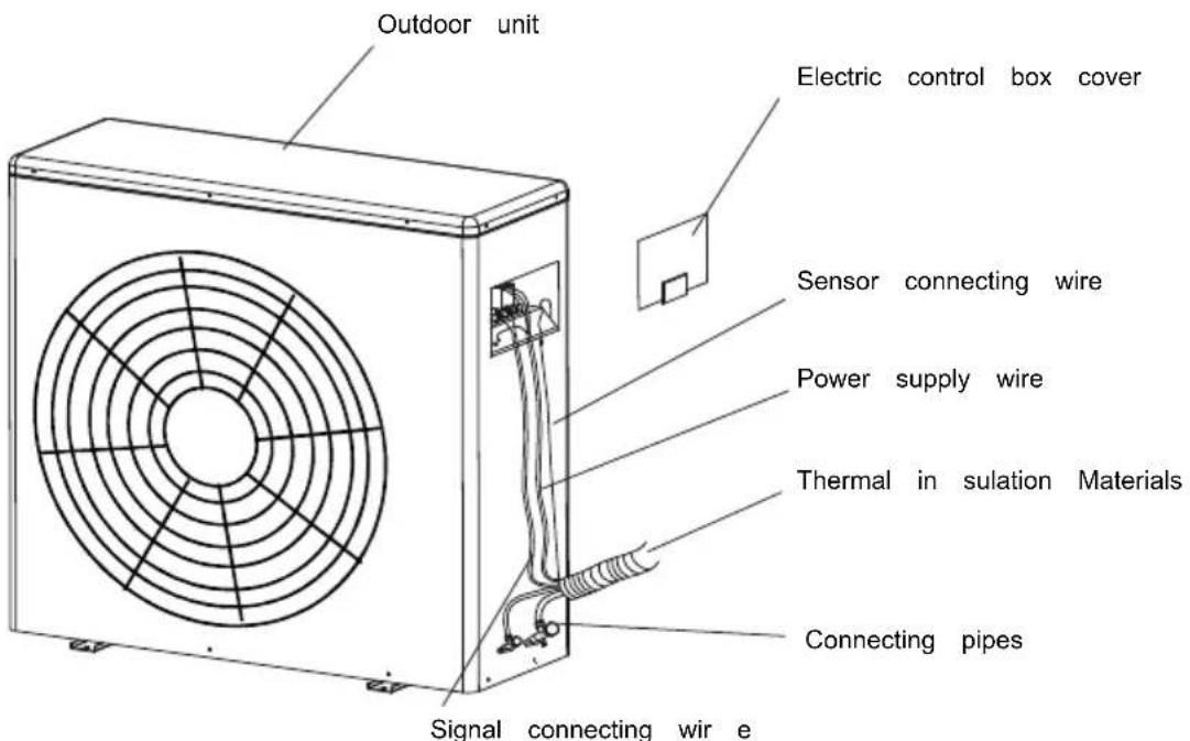
2. Binding treatment
Once the connecting wires have been properly connected, bind the connecting tubing, connecting wire and drain pipe by binding tapes
After binding treatment, the cross section is shown in the figure below:
Notice: Drain pipe must not be flattened during binding treatment.
Drain pipe outlet should be led to a place that can avoid affecting the environment.

If situations as follow occur, please cut off the electric power before contacting the dealer
- Open or close incorrectly Fuse or electric leakage protector breaks for several times.
- Objects or water into the AC
3. External wiring diagrams
The following wiring diagram is foruse with 12/18/24/30K models.

The following wiring diagram is suitable for 36/42K single-phase models.

The following wiring diagram is suitable for 48/55K single-phase models.

TEST RUN
Before testing
a. Check if piping, drainage and external wiring have been finished correctly. b. Check if the power supply complies with requirements; if there is refrigeration if the all wires and cables are correctly connected and well fixed.
■ Function test
a. After checking, energize your appliance and press the buttons on the cont to see if the buttons function; b. If LCD screen displays normally.
Notes
-
Please read this operating and installation instructions carefully.
-
Do not let air in or refrigerant out during installing or reinstalling the app v, as well as the
- Test run the air conditioner after finishing installation and keep the record bending.
-
Type of fuse for controller of indoor unit is 50T, rated specification is T Fuse for the whole unit is not supplied by the manufacturer, so the install g. employ a suitable fuse or other over-current protective device for the power circuit according to the maximum power input as required.
-
The air conditioner operates safely when ambient static pressure is 0.8\~1.05 atmosphere pressure.
Checks before operation
CAUTIONS
- Check that the wiring is not broken off or disconnected.
- Check that the air filter is installed.(Some air-conditioners have no air filters)
- Check that the outdoor unit air outlet or inlet is not blocked.
Before you clean the air conditioner, be sure to disconnect the power supply
Clean the air filter
- The air filter can prevent the dust or other particulate from going inside. In a blockage of the filter, the working efficiency of the air conditioner may greatly d Therefore, the filter must be cleaned once two weeks during long time usage.
- If the air conditioner is positioned in a dust place, the cleaning frequency of the must be increased.
- If the accumulated dust is too heavy to be cleaned, please replace the filter w one(replaceable air filter is an optional fitting).
■ Cassette Type
1. Open the air-in grill
Push the grill switches towards the middle simultaneously as indicated in sketch. Then pull down the air-in grill.
Caution:
The control box cables, which are originally connected with the main body elec terminators must be pulled off before doing as indicated below.

- Take out the air-in grill(together with the air filter shown in Sketch B) Pull the air-in grill down at 45 and lift it up to take out the grill.
- Dismantle the air filter
- Clean the air filter (Vacuum cleaner or pure water may be used to clean the dust accumulation is too heavy, please use soft brush and mild detergent to clean dry out in cool place).
ADJUSTING AIR FLOW DIRECTION
■ Cassette Type
While the unit is in operation, you can adjust the air flow louver to change the flow dire realize the room temperature evenly. Thus you can enjoy it more comfortably.
- Set the desired air flow direction.
Push the SWING button to adjust the louver to the desired position and push this button maintain the louver at this position.
- Adjust the air flow direction automatically.
Push the SWING button, the louver will swing automatically..
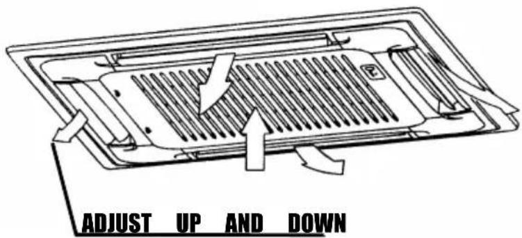
While this function is set, the swing fan of indoor unit runs; otherwise, the swing fan doesn't. When the air conditioner isn't in operation (including when TIMERON is set), the SWING button will be disabled
MAINTENANCE
WARNING
Before you clean the air conditioner, be sure to disconnect the power supply plug.
Cleaning the indoor unit and remote controller
CAUTIONS
- Use a dry cloth to wipe the indoor unit and remote controller.
A cloth dampened with cold water may be used on the indoor unit if it is very dirty. - Never use a damp cloth on the remote controller.
- Do not use a chemically-treated duster for wiping or leave such material on the unit for because it may damage or fade the surface of the unit.
- Do not use benzine, thinner, polishing powder, or similar solvents for cleaning. These may cause the plastic surface to crack or deform.
If you do not plan to use the unit for at least 1 month.
(1) Operate the fan for about half a day to dry the inside of the unit.
(2) Stop the air conditioner and disconnect power.
(3) Remove the batteries from the remote controller.
IMPORTANT SAFETY INFORMATION

▲CAUTI ON
Do not attempt to install this unit by yourself. This unit requires insta llation by qualified persons.
ADANGER
Do not attempt to service the unit yourself. This unit has no user serviceable components. Opening or removing the cover will expose you to danger ous voltage. Turn off the power supply will not prevent potential electric shock.
ADANGER
Never put hands or objects into the Air Outlet of indoor or ou units. These units are installed with a fan running at high speed. To touch the moving fan will cause serious injury.

DANGER
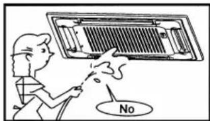
To avoid the risk of serious electrical shock, never sprinkle or spill water or liquid on unit.
▲WARNING
Ventilate the room regularly while the air conditioner is in use, especially if there is also a gas appliance i n use in this room. Failure to follow these directions may result in a loss of oxygen in the room.

▲WARNING
To prevent electric shock, turn off the power or disconnect the power supply plug before beginning any cleaning or other routine maintenance.

▲WARNING
Do not use liquid cleaners or aerosol cleaners, use a soft and dry cloth for cleaning the unit. To avoid electric shock, never attempt to clean the units by sprinkling water.

▲CAUTION
Do not use caustic household drain cleaners in the unit. Drain cleaners can quickly destroy the unit components (drain pan and heat exchanger coil etc).
▲NOTE
For proper performance, operate the unit in temperature and humidity ranges indicated in this 'owner's manual. If the unit is operated beyond these conditions, it may cause malfunctions of the unit or dew dripping from the unit.
■ Air flow direction adjustment procedure
Adjusting air flow direction
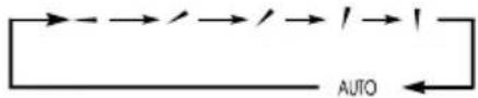
■ Up/down direction can be adjusted by using the AIRFLOW button on the remote controller. This button, each time pressed, changes the mode in the following sequence:
■ push the LOUVER button, changes the mode to swing louver. Push the button, to stop swing.

- When the room temperature controller(thermostat)trips in the heating mode or when the defrosting operation is conducted, the blow flap changes automatically to the horizontal position.
- When the heating operation has just started and the room temperature is still low, it may take a little time before the flap moves to the above sway operation angle.
- The flap may stop at the tilted down-blow position during the "Sway operation" in the heating mode,
■ About TIMER operation
About Amenity reservation
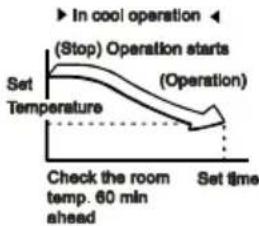
Amenity reservation function is provided to start the operation a little earlier so that the room temperature is near the optimum temperature at the timer ON time in case of starting the operation by TIMER ON/OFF.
- Mechanism Checking of the room temperature starts 60 minutes ahead of the timer ON time. Depending on the temperature at that time, operation starts 5 to 60 minutes ahead of the timer ON time. - Amenity reservation is the function only for COOL and HEAT operation mode (including AUTO). It does not actuate in DRY mode.
About SLEEP Operation
When the SLEEP operation is selected, the room temperature is automatically controlled with elapsed time so that the room isn't too cool during cooling or too warm during heating.
■ About power-off memory function
■ When the air conditioner disconnect the power suddenly, res tart it, the air conditione r operates at the mod e it did before power suddenly fa iled.
■ The wire controller don't have this function
| Error Code | Error Content | Error History Times | Error Definition and Protection |
| E0 | Indoor and outdoor communication failure | 1 | Hardware Error |
| E1 | Indoor ambient temperature | ature2 sensor | Hardware Error |
| E2 | Indoor fancoil temperature | ature3 sensor | Hardware Error |
| E3 | Outdoor fancoil temperature | ature4 sensor | Hardware Error |
| E4 | Abnormal system malfunction (lack of fluorine) 5 | 5 | Hardware Error |
| E5 | Model configuration error | 6 | Hardware Error |
| E6 | Indoor PG/DC fan failure | 7 | Hardware Error |
| E7 | Outdoor ambient temperature | ature8 sensor | Hardware Error |
| E8 | Outdoor exhaust temperature | ature9 sensor | Hardware Error |
| E9 | Outdoor IPM module failure/compressor drive failure | 10 | Hardware Error |
| EA | Outdoor current sensor failure | 11 | Hardware Error |
| Eb | PCB and display screen communication failure | 12 | Hardware Error |
| EC | Outdoor modules Communication failure | 13 | Hardware Error |
| EE | Outdoor EEPROM fault | 14 | Hardware Error |
| EF | Outdoor DC fan failure | 15 | Hardware Error |
| EH | Outdoor suction sensor failure | 16 | Hardware Error |
| EP | Outdoor compressor casing top failure | 17 | Hardware Error |
| EU | Outdoor voltage sensor failure | 18 | Hardware Error |
| Ej | Outdoor central coil temperature sensor failure | 30 | Hardware Error |
| En | Outdoor air pipe temperature sensor failure | 31 | Hardware Error |
| Ey | Outdoor liquid pipe temperature sensor failure | 32 | Hardware Error |
| P0 | IPM module protection | 19 | Others Error |
| P1 | Overvoltage and undervoltage protection | 20 | Others Error |
| P2 | Overcurrent protection | 21 | Others Error |
| P3 | Other protections | 22 | Others Error |
| P4 | Protection against excessive outdoor exhaust temperature | 23 | Others Error |
| P5 | Cooling protection against overcooling | 24 | Others Error |
| P6 | Cooling and anti overheating protection | 25 | Others Error |
| P7 | Heating and anti overheating protection | 26 | Others Error |
| P8 | Protection against high or low outdoor temperature | 27 | Remote control display adjustment |
| P9 | Compressor drive protection (abnormal load) | 28 | Others Error |
| PA | Communication failure/mode conflict | 29 | Others Error |
| F0 | Infrared human sensing sensor failure | 33 | Remote control display adjustment |
| F1 | Battery module failure | 34 | Remote control display adjustment |
| F2 | Exhaust temperature sensor failure protection | 35 | Others Error |
| F3 | Failure protection of outer tube temperature sensor | 36 | Others Error |
| F4 | Abnormal protection of refrigerant circulation | 37 | Others Error |
| F5 | PFC protection | 38 | Others Error |
| F6 | Compressor missing/reverse phase protection | 39 | Others Error |
| F7 | Module temperature protection | 40 | Others Error |
| F8 | Abnormal commutation of four-way valve | 41 | Others Error |
| F9 | Module temperature sensor circuit malfunction | 42 | Hardware Error |
| FA | Compressor phase current detection fault | 43 | Hardware Error |
| Fb | Cooling and heating overload protection limit frequency reduction | 44 | Remote control display adjustment |
| FC | High power protection limit/frequency reduction | 45 | Remote control display adjustment |
| FE | Module current (compressor phase current) protection limit/frequency reduction | 46 | Remote control display adjustment |
| FF | Module temperature protection limit/frequency reduction | 47 | Remote control display adjustment |
| FH | Drive protection limit/frequency reduction | 48 | Remote control display adjustment |
| FP | Anti condensation protection limit/frequency reduction | 49 | Remote control display adjustment |
| FU | Anti freezing protection limit/frequency reduction | 50 | Remote control display adjustment |
| Fj | Exhaust protection limit/frequency reduction | 51 | Remote control display adjustment |
| Fn | External AC current protection limit/frequency reduction | 52 | Remote control display adjustment |
| Fy | Fluorine deficiency protection | 53 | Others Error |
| H1 | High pressure switch malfunction | 54 | Hardware Error |
| H2 | Low pressure switch malfunction | 55 | Hardware Error |
| bf | TVOC sensor failure | 56 | Remote control display adjustment |
| bc | PM2.5 sensor failure | 57 | Remote control display adjustment |
| bj | Humidity sensor failure | 58 | Remote control display adjustment |
| bE | CO2 sensor malfunction | 59 | Hardware Error |
| bd | Fresh air fan failure | 60 | Hardware Error |
| d4 | Water full protection | 61 | Others Error |
| d5 | Access control protection | 62 | Hardware Error |
This air conditioner uses R32 refrigerant. The construction area for installation, operation and storage of the air conditioner must be larger than the minimum construction area. The minimum area for installation is determined by:
- Refrigerant charging quantity for the entire system (ex-factory charging quantity + additional charging quantity);
- Checking out in the applicable tables:
(1) For indoor unit, confirm the model of indoor unit and check the corresponding table.
(2) For outdoor unit that is installed or placed indoors, select the corresponding table according to the height of the room.
| Height of the room | Select the applicable table |
| < 0m | Floor standing type |
| ≥ 1.8m | Wall mounted type |
| ≥ 2.2m | Ceiling type |
- Refer to the following table to check out the minimum construction area.
| Ceiling type | Wall mounted type | Floor standing type | |||||
| Weight (kg) | Area (m2) | Weight (kg) | Area (m2) | Weight (kg) | Area (m2) | ||
| <1.224 | — | <1.224 | — | <1.224 | — | ||
| 1.224 0.956 | 1.224 1.43 1.224 | 12.9 | |||||
| 1.4 | 1.25 | 1.4 | 1.87 | 1.4 | 16.8 | ||
| 1.6 | 1.63 | 1.6 | 2.44 | 1.6 | 22.0 | ||
| 1.8 | 2.07 | 1.8 | 3.09 | 1.8 | 27.8 | ||
| 2.0 | 2.55 | 2.0 | 3.81 | 2.0 | 34.3 | ||
| 2.2 | 3.09 | 2.2 | 4.61 | 2.2 | 41.5 | ||
| 2.4 | 3.68 | 2.4 | 5.49 | 2.4 | 49.4 | ||
| 2.6 | 4.31 | 2.6 | 6.44 | 2.6 | 58.0 | ||
| 2.8 | 5.00 | 2.8 | 7.47 | 2.8 | 67.3 | ||
| 3.0 | 5.74 | 3.0 | 8.58 | 3.0 | 77.2 | ||
| 3.2 | 6.54 | 3.2 | 9.76 | 3.2 | 87.9 | ||
| 3.4 | 7.38 | 3.4 | 11.0 | 3.4 | 99.2 | ||
| 3.6 | 8.27 | 3.6 | 12.4 | 3.6 | 111 | ||
| 3.8 | 9.22 | 3.8 | 13.8 | 3.8 | 124 | ||
| 4.0 | 10.2 | 4.0 | 15.3 | 4.0 | 137 | ||
| 4.2 | 11.3 | 4.2 | 16.8 | 4.2 | 151 | ||
| 4.4 | 12.4 | 4.4 | 18.5 | 4.4 | 166 | ||
| 4.6 | 13.5 | 4.6 | 20.2 | 4.6 | 182 | ||
| 4.8 | 14.7 | 4.8 | 22.0 | 4.8 | 198 | ||
| 5.0 | 16.0 | 5.0 | 23.8 | 5.0 | 215 | ||
| 5.2 | 17.3 | 5.2 | 25.8 | 5.2 | 232 | ||
| 5.4 | 18.6 | 5.4 | 27.8 | 5.4 | 250 | ||
| 5.6 | 20.0 | 5.6 | 29.9 | 5.6 | 269 | ||
| 5.8 | 21.5 | 5.8 | 32.1 | 5.8 | 289 | ||
| 6.0 | 23.0 | 6.0 | 34.3 | 6.0 | 309 | ||
| 6.2 | 24.5 | 6.2 | 36.6 | 6.2 | 330 | ||
| 6.4 | 26.1 | 6.4 | 39.1 | 6.4 | 351 | ||
| 6.6 | 27.8 | 6.6 | 41.5 | 6.6 | 374 | ||
| 6.8 | 29.5 | 6.8 | 44.1 | 6.8 | 397 | ||
| 7.0 | 31.3 | 7.0 | 46.7 | 7.0 | 420 | ||
| 7.2 | 33.1 | 7.2 | 49.4 | 7.2 | 445 | ||
| 7.4 | 34.9 | 7.4 | 52.2 | 7.4 | 470 | ||
| 7.6 | 36.9 | 7.6 | 55.1 | 7.6 | 496 | ||
| 7.8 | 38.8 | 7.8 | 58.0 | 7.8 | 522 | ||
| 8.0 | 40.8 | 8.0 | 61.0 | 8.0 | 549 | ||

IMPORTANT INFORMATION FOR CORRECT DISPOSAL OF THE PRODUCT IN ACCORDANCE WITH EC DIRECTIVE 2002/96/EC.
At the end of its working life, the product must not be disposed of as urban waste. It must be taken to a special local authority differentiated waste collection centre or to a dealer providing this service.
Disposing of a household appliance separately avoids possible negative consequences for the environment and health deriving from inappropriate disposal and enables the constituent materials to be recovered to obtain significant savings in energy and resources. As a reminder of the need to dispose of household appliances separately, the product is marked with a crossed-outwheeled dustbin.
- SAFETY NOTICE
- CONTENTS
- PRECAUTION
- NOTE
- OPERATING CONDITION
- NOISE POLLUTION
- FEATURES OF PROTECTOR
- INSPECTION
- FEATURES OF HEATING MODE
- PREHEAT
- DEFROST
- PARTS AND FUNCTIONS
- REQUIREMENTS
- NOTICE
- CONSTITUTION OF PANEL
- DISPLAY PANEL
- ◇ DISPLAY PANEL
- INDOOR UNIT INSTALLATION
- INSTALLATION LOCATIONS
- CAUTIONS
- INSTALLATION SPACE
- HEIGHT BETWEEN CEILING AND FLOOR
- CEILING HOLE AND THE HOOK INSTALLATION
- PANEL INSTALLATION
- CAUTION
- DRAINAGE PIPE INSTALLATION
- FLEXIBLE HOSE
- CONNECTION PROCEDURE
- HEAT INSULATION
- DRAINAGE UPWARD
- DRAINAGE TEST
- MOTOR SOUND TEST
- INSTALLATION OF PANEL
- BODY DIMENSION
- BODY DIMENSION:580X255X580
- INSTALL ATION OF PANEL
- FIGURE OF BODY SIZE
- OUTDOOR UNIT INSTALLATION
- MOVE OUTDOOR UNIT IN
- REFRIGERANT PIPE
- INSTALLATION
- PRE-INSTALLATION PRECAUTIONS
- USER GUIDELINE
- PRECAUTIONS
- UNIT BODY INSTALLATION
- REFRIGERANT PIPE INSTALLATION
- PIPE DIMENSION AND WAYS OF INSTALLATION
- FIARING
- STOP VALVE OPERATION ITEM
- JUNCTION FIXTURE
- AIR PURGING
- ELECTRIC WIRING
- WARNING
- PANEL WIRING
- TERMINAL BOARD DIAGRAM
- STEPS OF EXTERNAL WIRING CONNECTION
- BINDING TREATMENT
- EXTERNAL WIRING DIAGRAMS
- TEST RUN
- BEFORE TESTING
- FUNCTION TEST
- NOTES
- CHECKS BEFORE OPERATION
- CLEAN THE AIR FILTER
- CASSETTE TYPE
- OPEN THE AIR-IN GRILL
- ADJUSTING AIR FLOW DIRECTION
- MAINTENANCE
- IMPORTANT SAFETY INFORMATION
- ▲CAUTI ON
- ADANGER
- DANGER
- ▲WARNING
- ▲CAUTION
- ▲NOTE
- AIR FLOW DIRECTION ADJUSTMENT PROCEDURE
- ABOUT TIMER OPERATION
- ABOUT SLEEP OPERATION
- ABOUT POWER-OFF MEMORY FUNCTION
- IMPORTANT INFORMATION FOR CORRECT DISPOSAL OF THE PRODUCT IN ACCORDANCE WITH EC DIRECTIVE 2002/96/EC
Brand : Yamato
Model : R32 YC42T1
Category : Air Conditioning