EU2SYS-96 - Food Warmer Alto-Shaam - Free user manual and instructions
Find the device manual for free EU2SYS-96 Alto-Shaam in PDF.


| Product Type | Commercial Food Warmer |
| Model | EU2SYS-96 |
| Brand | Alto-Shaam |
| Dimensions (W x D x H) | 35.5 x 28.4 x 14.5 inches |
| Weight | 80 lbs |
| Power Supply | 120V, 60Hz, 1500W |
| Temperature Range | 150°F – 200°F |
| Capacity | Holds multiple full-size steam table pans |
| Construction Material | Stainless steel interior and exterior |
| Controls | Adjustable thermostat with dial |
| Safety Features | Overheat protection, safety shut-off |
| Certifications | NSF, UL listed |
| Cleaning | Removable drip tray; wipe with mild detergent |
| Warranty | 2 years parts and labor |
| Usage | Indoor, commercial food holding |
Frequently Asked Questions - EU2SYS-96 Alto-Shaam
User questions about EU2SYS-96 Alto-Shaam
0 question about this device. Answer the ones you know or ask your own.
Ask a new question about this device
Download the instructions for your Food Warmer in PDF format for free! Find your manual EU2SYS-96 - Alto-Shaam and take your electronic device back in hand. On this page are published all the documents necessary for the use of your device. EU2SYS-96 by Alto-Shaam.
USER MANUAL EU2SYS-96 Alto-Shaam
Heated Display Cases
Full Service or Self Service
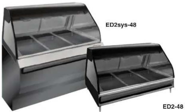

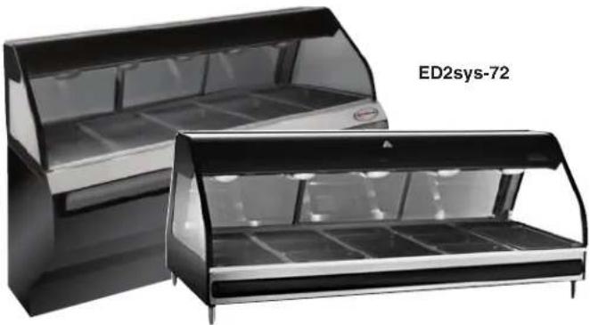
ED2-72

ED2-96
Models:
ED2-48; ED2SYS-48
ED2-48/P; ED2SYS-48/P
EU2SYS-48; EU2SYS-48/P
ED2-72; ED2SYS-72
ED2-72/P; ED2SYS-72/P
ED2-72/PL; ED2SYS-72/PL
ED2-72/PR; ED2SYS-72/PR
EU2SYS-72; EU2SYS-72/P
EU2SYS-72/PL
EU2SYS-72/PR
ED2-96; ED2SYS-96
ED2-96/PL; ED2SYS-96/PL
ED2-96/PR; ED2SYS-96/PR
EU2SYS-96; EU2SYS-96/P
EU2SYS-96/PL
EU2SYS-96/PR
- INSTALLATION
• OPERATION
- MAINTENANCE
HALO HEAT.

W164 N9221 Water Street • P.O. Box 450 • Menomonee Falls, Wisconsin 53052-0450 USA
PHONE: 262.251.3800 • 800.558.8744
USA/CANADA FAX: 262.251.7067 • 800.329.8744
U.S.A. ONLY
www.alto-shaam.com
ALTO-SHAAM®
Delivery....1
Unpacking 1
Safety Procedures and Precautions....2
Installation3
Installation Requirements 3
Clearance Requirements 3
Leveling 3
Cutting Board Installation 3
Dimension Drawings 4-6
Electrical Connection 7
Options & Accessories 8
Operating Instructions
User Safety Information 9
Start-up Operation 9
Operating Procedures.... 10
Pan Configurations ..... 11-13
General Holding Guidelines 14
Care and Cleaning
Cleaning and Preventative Maintenance ..... 15
Protecting Stainless Steel Surfaces 15
Cleaning Agents 15
Cleaning Materials 15
Equipment Care 16
Clean the Probes 16
Clean Daily 16
Sanitation 17
Service
Cable Replacement Kits 18
ED2 Series, Full Assembly, Front View ..... 19-22
ED2 Series, Base Assembly 23
ED2 Series, Inner Top Assembly 24
BU2 Cart, Full Assembly 25
BU2 Short Cart, Full Assembly 26
Wire Diagrams
ED2(SYS)-48 & /P, 120/208-240V.....27
ED2(SYS)-48 w/outlets, 120/208-240V ..... 28
ED2(SYS)-48 & /P, 230V 29
ED2(SYS)-72 & /P, /PL, /PR, 120/208-240V ... 30
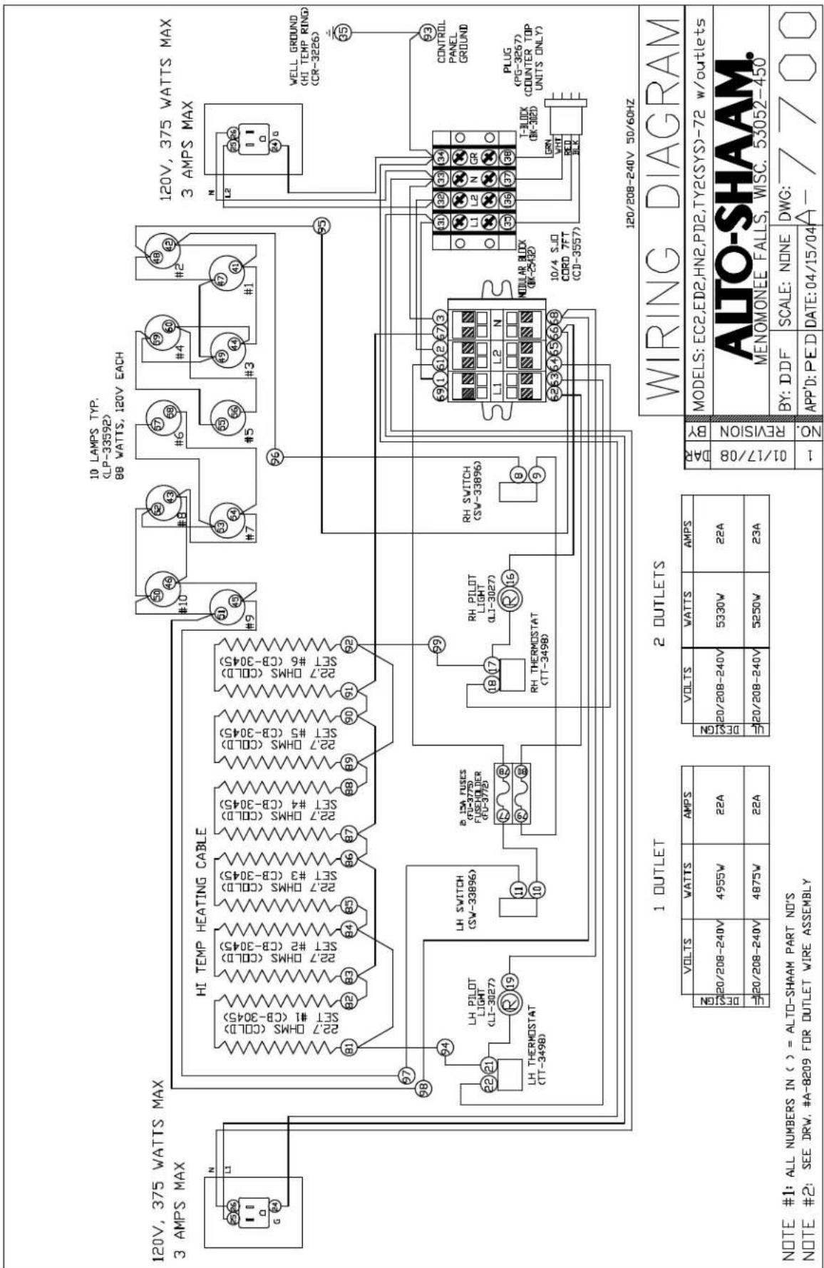
ED2(SYS)-72 w/outlets, 120/208-240V ..... 31
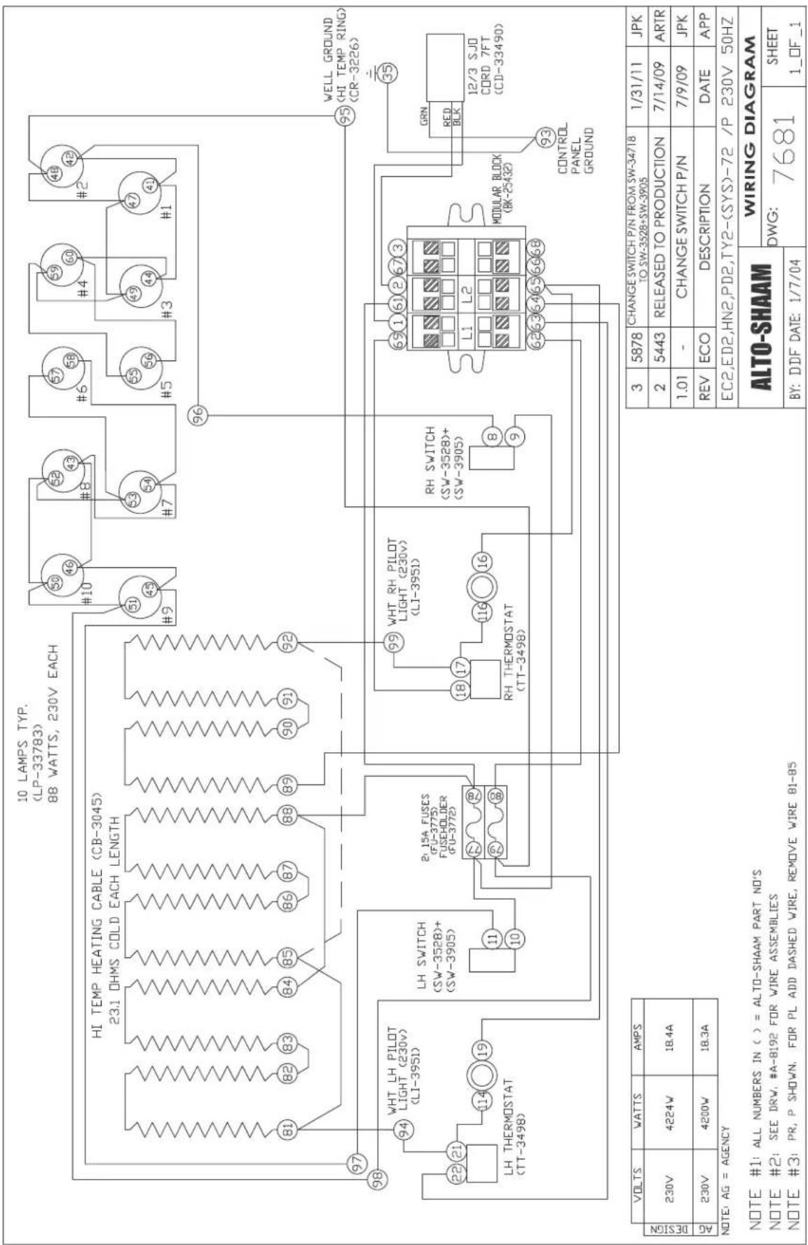
ED2(SYS)-72 & /P, 230V 32
ED2(SYS)-72 & /P, /PL, /PR, 380-415V ..... 33
ED2(SYS)-96 & /P, /PL, /PR, 120/208-240V ... 34
ED2(SYS)-96 w/outlets, 120/208-240V ..... 35
ED2(SYS)-96 & /P, 230V 36
ED2(SYS)-96 & /P, /PL, /PR, 380-415V ..... 37
Deli Probe Display Optional Kit 38
BU2-48; BU2-48 Short 39
BU2-72; BU2-72 Short 40
BU2-96; BU2-96 Short 41
Warranty
Transportation Damage and Claims .. Back Cover
Limited Warranty. Back Cover
ALTO-SHAAM®
DEIVErY
This Alto-Shaam appliance has been thoroughly tested and inspected to ensure only the highest quality unit is provided. Upon receipt, check for any possible shipping damage and report it at once to the delivering carrier. See Transportation Damage and Claims section located in this manual.
This appliance, complete with unattached items and accessories, may have been delivered in one or more packages. Check to ensure that all standard items and options have been received with each model as ordered.
Save all the information and instructions packed with the appliance. Complete and return the warranty card to the factory as soon as possible to ensure prompt service in the event of a warranty parts and labor claim.
This manual must be read and understood by all people using or installing the equipment model. Contact the Alto-Shaam Tech Team Service Department if you have any questions concerning installation, operation, or maintenance.
notE: All claims for warranty must include the full model number and serial number of the unit.
unPaCKInG
- Carefully remove the appliance from the carton or crate.
notE: Do not discard the carton and other packaging material until you have inspected the unit for hidden damage and tested it for proper operation.

- Read all instructions in this manual carefully before initiating the installation of this appliance.
DO NOT DISCARD THIS MANUAL.
This manual is considered to be part of the appliance and is to be provided to the owner or manager of the business or to the person responsible for training operators. Additional manuals are available from the Alto-Shaam Tech Team Service Department.
- Remove all protective plastic film, packaging materials, and accessories from the appliance before connecting electrical power. Store any accessories in a convenient place for future use.
saFEtY ProCEDurEs and PrECautlons
Knowledge of proper procedures is essential to the safe operation of electrically and/or gas energized equipment. In accordance with generally accepted product safety labeling guidelines for potential hazards, the following signal words and symbols may be used throughout this manual.
DanGEr

Used to indicate the presence of a hazard that WILL cause severe personal injury, death, or substantial property damage if the warning included with this symbol is ignored.
warnInG

Used to indicate the presence of a hazard that CAN cause personal injury, possible death, or major property damage if the warning included with this symbol is ignored.
Caution

Used to indicate the presence of a hazard that can or will cause minor or moderate personal injury or property damage if the warning included with this symbol is ignored.
Cautlon
Used to indicate the presence of a hazard that can or will cause minor personal injury, property damage, or a potential unsafe practice if the warning included with this symbol is ignored.
notE: Used to notify personnel of installation, operation, or maintenance information that is important but not hazard related.
- This appliance is intended to hold foods for the purpose of human consumption. No other use for this appliance is authorized or recommended.
- This appliance is intended for use in commercial establishments where all operators are familiar with the purpose, limitations, and associated hazards of this appliance. Operating instructions and warnings must be read and understood by all operators and users.
- Any troubleshooting guides, component views, and parts lists included in this manual are for general reference only and are intended for use by qualified technical personnel.
- This manual should be considered a permanent part of this appliance. This manual and all supplied instructions, diagrams, schematics, parts lists, notices, and labels must remain with the appliance if the item is sold or moved to another location.
notE

For equipment delivered for use in any location regulated by the following directive: DO NOT DISPOSE OF ELECTRICAL OR ELECTRONIC EQUIPMENT WITH OTHER MUNICIPAL WASTE.
DANGER

IMPROPER INSTALLATION, ALTERATION, ADJUSTMENT, SERVICE, OR MAINTENANCE COULD RESULT IN SEVERE INJURY, DEATH, OR CAUSE PROPERTY DAMAGE. READ THE INSTALLATION, OPERATING AND MAINTENANCE INSTRUCTIONS THOROUGHLY BEFORE INSTALLING OR SERVICING THIS EQUIPMENT.
CAUTION

METAL PARTS OF THIS EQUIPMENT BECOME EXTREMELY HOT WHEN IN OPERATION. TO AVOID BURNS, ALWAYS USE HAND PROTECTION WHEN OPERATING THIS APPLIANCE.
CAUTION

TO PREVENT PERSONAL INJURY, USE CAUTION WHEN MOVING OR LEVELING THIS APPLIANCE.
SITE INSTALLATION
In order to maintain established National Sanitation Foundation standards, all stationary floor models must be sealed to the floor with a R.T.V. or silastic meeting N.S.F. requirements or have 6" (152mm) unobstructed clearance beneath the unit.
- The appliance must be installed on a stable and level surface.
- DO NOT install this appliance in any area where it may be affected by any adverse conditions such as steam, grease, dripping water, high temperatures, or any other severely adverse conditions.
- DO NOT install a heated display case near a cold air source such as a freezer, air conditioning vents, or in any area where outside air fluctuation can affect performance.
- This appliance must be kept free and clear of any obstructions blocking access for maintenance or service.
MINIMUM CLEARANCE REQUIREMENTS
Counter and table units must be mounted on legs of a sufficient 4" (102mm) or 6" (152mm) height depending on unit length to provide minimum unobstructed space beneath the unit. These legs are supplied with the unit. Warranty will become null and void if these directions are not followed.

A number of adjustments are associated with initial installation and start-up. It is important that these adjustments be conducted by a qualified service technician. Installation and start-up adjustments are the responsibility of the dealer or user. These adjustments include but are not limited to thermostat calibration, door adjustment, leveling, electrical hook-up and installation of optional casters or legs.
LEVELING

Level the appliance from side-to-side and front-to-back with the use of a spirit level.
We recommend checking the level periodically to make certain the floor has not shifted nor the appliance moved.
NOTE: Failure to properly level this appliance can cause improper function.
Cutting board installation:
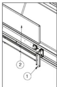
- Place both brackets in the closed (down) position.
- Slide cutting board back flanges down onto brackets.
- Pivot installed board to a horizontal position and slide bracket down to lock in the open position. (NOT SHOWN)
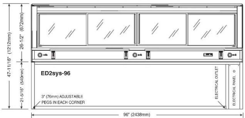
Installation
sltE Installation
ED2 & ED2sYs sErIEs
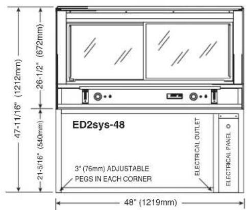

ED2 PrOfIIE

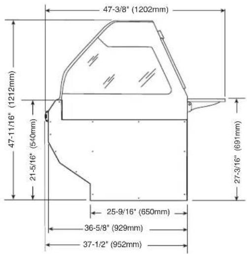
ED2sys PrOfllE
sltE Installation
Eu2sYs sErlEs


EU2sys PrOfIIE
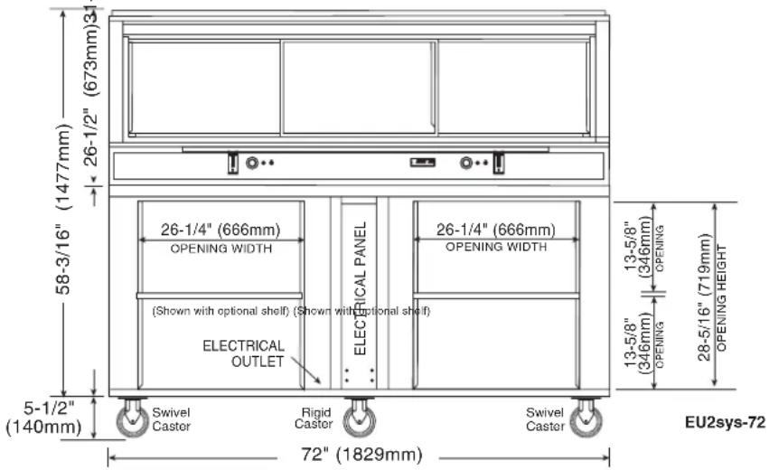

ED2 & EU2 Series Operation & Care Manual • 5
Installation
sItE Installation
Eu2sYs sHort sErlEs
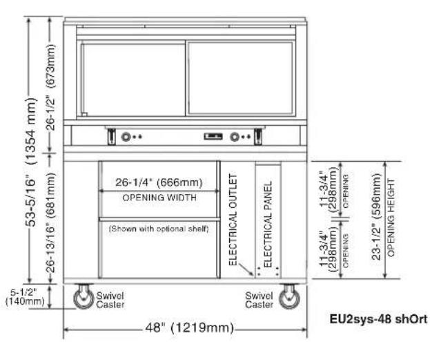

EU2sys PrOfIIE
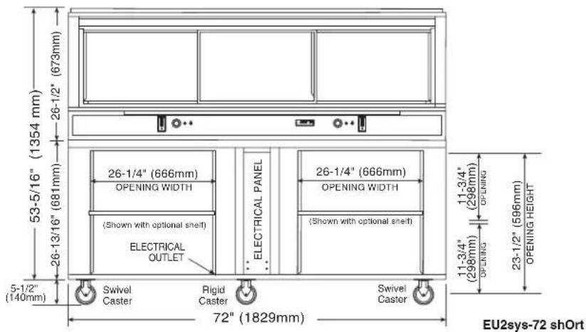

ELECTRICAL CONNECTION
The appliance must be installed by a qualified service technician. The oven must be properly grounded in accordance with the National Electrical Code and applicable local codes.
DANGER

To avoid electrical shock, this appliance MUST be adequately grounded in accordance with local electrical codes or, in the absence of local codes, with the current edition of the National Electrical Code ANSI/NFPA No. 70. In Canada, all electrical connections are to be made in accordance with CSA C22.1, Canadian Electrical Code Part 1 or local codes.

Plug the unit into a properly grounded receptacle ONLY, positioning the unit so that the plug is easily accessible in case of an emergency. Arcing will occur when connecting or disconnecting the unit unless all controls are in the "OFF" position.
ELECTRICAL
ED2-48, ED2SYS-48, EU2SYS-48 SERIES
| VOLTAGEPHASECYCLE/HZAMPSKW | ||
| 120/208-240 (AGCY) | 1 50/60 13.8 3.3 | NEMA L14-20P20A, 250V PLUG |
| AT 208 | 1 50/60 11.6 2.5 | |
| AT 240 | 1 50/60 13.0 3.1 | |
| 230 (AGCY) 1 50 12.6 2.9 | BARE END, NO PLUG | |
| 230 1 50 12.6 2.9 | ||
ED2-72, ED2SYS-72, EU2SYS-72 SERIES
| VOLTAGEPHASECYCLE/HZAMPSKW | ||||
| 120/208-240 (AGCY) | 1 50/60 18.75 4.5 | NEMA L14-30P30A, 250V PLUG | ||
| AT 208 | 1 50/60 19.0 4.6 | |||
| AT 240 | 1 50/60 19.0 4.6 | |||
| 230 (AGCY) 1 50 18.3 4.2 | BARE END, NO PLUG | |||
| 230 1 50 18.4 4.2 | ||||
| 380-415 | 3 50 | 9.7 | 4.4 | |
| AT 380 | 3 50 | 9.3 | 3.9 | BARE END, NO PLUG |
| AT 415 | 3 50 | 10.1 4.6 | ||
ED2-96, ED2SYS-96, EU2SYS-96 SERIES
| VOLTAGEPHASECYCLE/HZAMPSKW | |||
| 120/208-240 (AGCY) | 1 50/60 24.0 5.2 | NEMA L14-30P30A, 250V PLUG | |
| AT 208 | 1 50/60 24.0 5.2 | ||
| AT 240 | 1 50/60 24.0 5.2 | ||
| 230 (AGCY) 1 50 24.9 5.7 | BARE END, NO PLUG | ||
| 230 1 50 24.3 5.6 | |||
| 380-415 (AGCY) | 3 50 10.7 6.5 | BARE END, NO PLUG | |
| AT 380 | 3 50 9.7 5.2 | ||
| AT 415 | 3 50 10.3 6.2 | ||
Proper receptacle or outlet configuration or permanent wiring for this unit must be installed by a licensed electrician in accordance with applicable local electrical codes.

DANGER

ELECTRICAL CONNECTIONS MUST BE MADE BY A QUALIFIED SERVICE TECHNICIAN IN ACCORDANCE WITH APPLICABLE ELECTRICAL CODES.

DANGER

ENSURE POWER SOURCE MATCHES VOLTAGE STAMPED ON APPLIANCE NAMEPLATE.
rEGArDING INtErNAtIONAI stANDArD UNIts:
If the unit is not equipped with flexible cord and plug, an all-pole country approved disconnection device which has a contact separation of at least 3mm in all poles must be incorporated in the fixed wiring for disconnection. When using a cord without a plug, the green/yellow conductor shall be connected to the terminal which is marked with the ground symbol. If a plug is used, the socket outlet must be easily accessible. If the power cord needs replacement, use a similar one obtained from the distributor.
For CE approved units: To prevent an electrical shock hazard between the appliance and other appliances or metal parts in close vicinity, an equalization-bonding stud is provided. An equalization bonding lead must be connected to this stud and the other appliances / metal parts to provide sufficient protection against potential difference. The terminal is marked with the following symbol.
Hard wired models:
Hard wired models must be equipped with a country certified external allpole disconnection switch with sufficient contact separation.
If a power cord is used for the connection of the product an oil resistant cord like H05RN or H07RN or equivalent must be used.
NOTE: CE approved appliances must be connected to an electrical circuit that is protected by an external GFCI outlet.
Wire diagrams are located in the
literature package that came with the unit.
Installation
| fACtOry INSTAIIED OPtIONs | |||
| DEsCrlPtION ED2-48 sErlEs ED2-72 | sErlEs ED2-96 sErlEs | ||
| INDEPENDENT ELECTRICAL OUTLET | 5001781 5001781 5001781 | ||
| TEMPERATURE PROBE | 5004916 5004917 5004918 | ||
ACCEssOrlEs
| DEsCrIPtION ED2-48 sErlEs ED2-72 | sErlEs ED2-96 sErlEs | |||
| BUTTING KIT (SEAMLESSLY CONNECT MULTIPLE SYSTEMS TOGETHER) | 5008523 50085 | 23 5008523 | ||
| CARVING STATION | 5001874 50018 | 74 5001874 | ||
| CASTERS, PLATE (EU2SYS ONLY) | 5" (127mm), RIGID | CS-2025 (2 REQ'D) | CS-2025 (2 REQ'D) | CS-2025 (2 REQ'D) |
| 5" (127mm) | , SWIVEL WITH BRAKE | CS-2026 (2 REQ'D) | CS-2026 (4 REQ'D) | CS-2026 (4 REQ'D) |
| PAN INSERT, SELF SERVICE | 4" (102mm) DEEP | 1001990 10019 | 91 — | |
| PLATFORM SCALE | RIGHT HAND | 5001307 50013 | 07 5001307 | |
| LEFT HAND | 5001308 50013 | 08 5001308 | ||
| SHELF, STAINLESS STEEL (EU2SYS ONLY) | 5005786 50057 | 86 5005786 | ||
| SHEET PAN DIVIDER BAR PACKAGE | ED2-48, -48/P | 5002802 — — | ||
| ED2-72, -72/P | — 5002803 — | |||
| ED2-72/PL, -72/PR | — 5002804 — | |||
| ED2-96 | — — 5002805 | |||
| ED2-96/PL, -96/PR | — — 5002806 | |||
| SHORT BASE (EU2SYS ONLY)OVERALL HEIGHT REDUCED BY 4-3/4" (121mm) | 304332 | 304342 | 304352 | |
| THERMOSTAT GUARD COVER PLATE | 5007660 (2 REQ'D) | 5007660 (2 REQ'D) | 5007660 (3 REQ'D) | |
| WORK SHELF WITH GRAVY LANE | ED2-48, -48/P | 5005638 — — | ||
| ED2-72, -72/P, -72/PL, -72/PR | — 5005639 — | |||
| ED2-96, -96/P, -96/PL, -96/PR | — — 5005640 | |||
oPEratInG InstruCtions
usEr saFEtY InForMatlon
Cautlon

METAL PARTS OF THIS EQUIPMENT BECOME EXTREMELY HOT WHEN IN OPERATION. TO AVOID BURNS, ALWAYS USE HAND PROTECTION WHEN OPERATING THIS APPLIANCE.
The Alto-Shaam heated display case is intended for use in commercial establishments by qualified operating personnel where all operators are familiar with the purpose, limitations, and associated hazards of this appliance. Operating instructions and warnings must be read and understood by all operators and users.
warnInG

Hood glass extended to the full, upright portion is stabilized through the use of gas struts designed for the full, load-bearing weight. These struts could weaken or fail due to wear, environmental conditions or aging. OPERATORS SHOULD BE AWARE OF ANY INCREASE IN EFFORT TO LIFT THE HOOD AND INITIATE AN IMMEDIATE GAS STRUT SAFETY CHECK. DO NOT LIFT THE HOOD IN THIS CONDITION.

start-uP oPEration
BEForE Initial usE:
Interior display case surfaces must be heated to remove surface oils and the accompanying odor produced during the first use of the appliance.
Remove pans. Turn thermostats to the "ON" position. Set thermostats to the 10 setting. Allow the unit to heat for 30 minutes or until no odor is detected.

DanGEr

DisConnECT unit FroM PowEr sourCE BEForE CIEanInG or sErVICInG.
PrEHEatInG:
The unit should be preheated at the 10 setting for a minimum of 30-45 minutes before loading the case with hot food. Follow the operating instructions indicated on the next page of this manual.
DanGEr

To avoid electrical shock, this appliance MUST be adequately grounded in accordance with local electrical codes or, in the absence of local codes, with the current edition of the National Electrical Code ANSI/NFPA No. 70. In Canada, all electrical connections are to be made in accordance with CSA C22.1, Canadian Electrical Code Part 1 or local codes.

oPEratInG InstruCtions
oPEratInG ProCEDurEs
1. Do not aDD watEr to DIsPlaY CasE
Halo Heat display cases maintain a constant but gentle temperature and eliminate much of the moisture loss associated with conventional display cases. Because of this gentle heat, it is not necessary to add water to the display case. As a matter of fact, adding water is not recommended since water will accelerate the deterioration of the product, and may damage the unit voiding the warranty.
2. PlaCE DIVIDERS anD sErVInG Pans In CasE
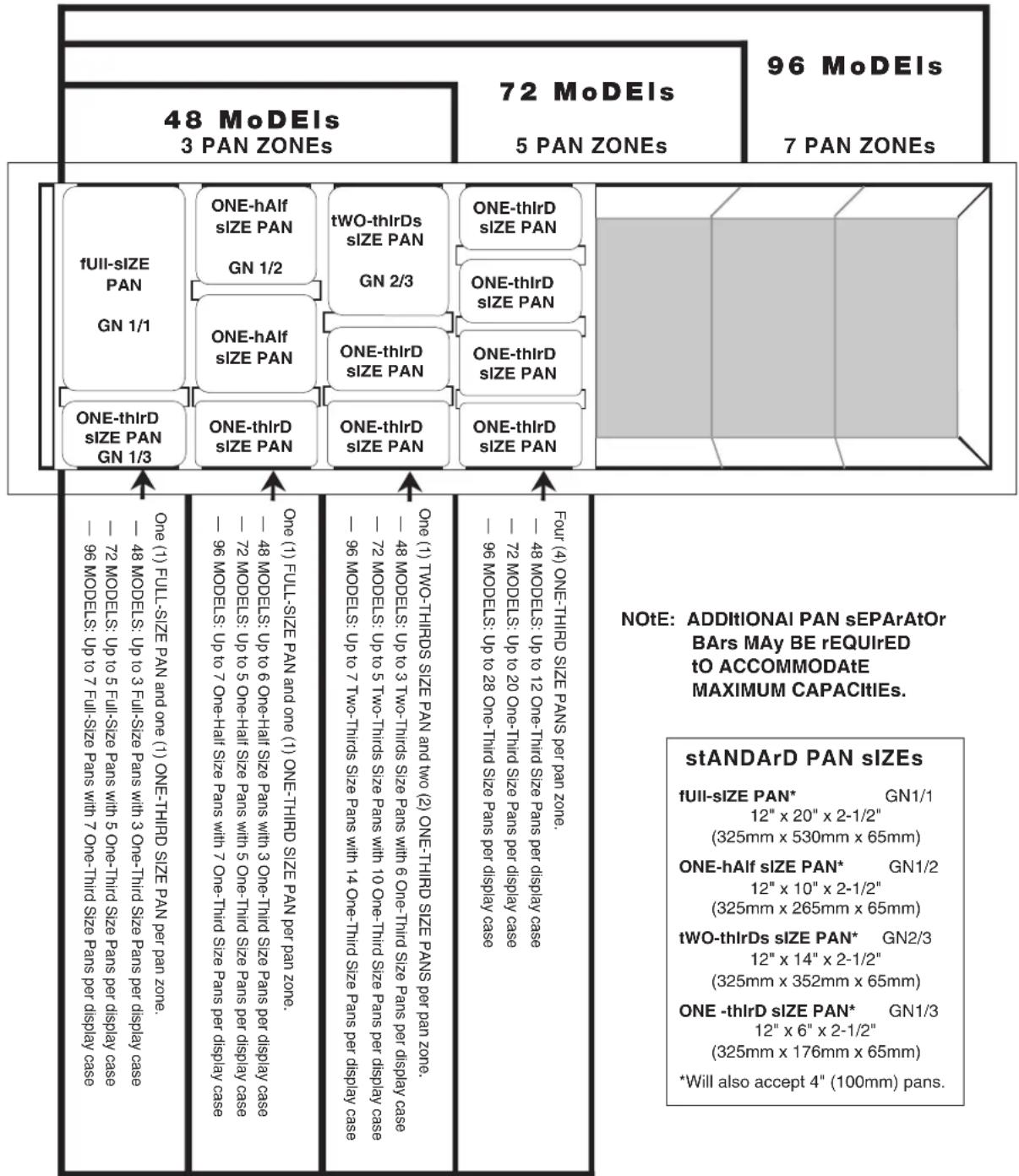
Refer to the pan layout diagrams for different types of pan accommodations. A complete pan configuration layout is located in this manual. It is VERY important to note, no matter what type of pan configuration chosen, pan separator bars or divider bars must be used to close all gaps between pans, and all gaps between the pans and the edges of the display case. If these gaps are not closed, heat will escape from the bottom of the case into the display area. As a consequence, heat distribution will be uneven and uniform temperature will be difficult to hold. If needed, additional pan divider bars are available. The supplied self-serve pan inserts with wire grids are for use with pre-packaged foods in the self-serve sections of the units.
3. turn DIsPlaY IIGHts "on" anD sEt tHE tHERMostat(s) at numBER "10" to PrEHEat
A indicator light will illuminate when the thermostat(s) is (arc) turned "ON." The indicator(s) will remain lit as long as the unit is preheating or calling for heat. The unit should be preheated at the 10 setting for a minimum of 30-45 minutes before loading the case with hot food. When preheating is completed, or whenever the unit reaches any temperature set by the operator between 1 and 10, the indicator light(s) will go "OUT".
4. IoaD Hot FooDs Into DIsPlaY CasE
Be certain only hot food is transferred into the display case. Before loading food into the case, use a pocket-type meat thermometer to make certain all products have reached an internal temperature of 140° to 160° F ( 60° to 71° C). If any food product is not at proper serving temperature, use a Halo Heat cooking and holding oven, set at 250° to 275° F ( 121° to 135° C), or a Combitherm oven to bring the product within the correct temperature range.
- Use hand protection when handling hot items.
- Be certain only hot PREPACKAGED foods in appropriate heat tested containers are used in the self-service section of the display case.
- Do not stack food containers.
5. rEsEt tHErMostat(s) as nEEDED
After all products are loaded into the display case and the doors are closed, it is necessary to reset the thermostat(s). For fully enclosed sections, reset the thermostat to the number "8" setting. Cases with a self-service section should be maintained between number "9" and number "10" for the self-service section only. THESE SETTINGS WILL NOT NECESSARILY BE FINAL. Since proper temperature range depends on the type of products and the quantities being held, it is necessary to periodically use a pocket thermometer to check each item to make certain the correct temperatures are being maintained. Proper temperature range is between a minimum of 140° and 160°F (60° and 71°C). Normally, this will require a thermostat setting of between number "6" and "8" in fully enclosed cases. Self-service cases or sections will always require a higher thermostat setting.
6. PlaCEMENT of FooD ProBE
If the unit is equipped with the probe accessory, wipe each probe and probe tip with a disposable alcohol pad to clean and sanitize before using. If the probe is left in its bracket, the LED temperature display will indicate the ambient air temperature inside the case. To place a probe into food kept in the case, remove the probe from the bracket and push the probe tip halfway into the product, positioning the tip at the center of the food mass. If placing into solid foods such as meat roast or poultry breasts, push the probe in from a straight downward position or in from the side to the center position. If placing into a semi-liquid or liquid product, the probe cable will probably need to be secured to keep the probe positioned properly. Do not let the probe tip touch the edges or sides. Tape the probe cable to the lip or edge of the container. Wipe each probe tip with a clean paper towel to remove food debris after each use. Follow by wiping probes with a disposable alcohol pad, and return each probe to the proper bracket position.
7. sErVE FrEsH Hot FooD
Keep hot foods looking fresh. Occasionally stir or rotate food as needed. Serve food products in appropriate heat tested packages or containers. Keep display case doors closed after serving. Wipe spills immediately to assure maximum eye appeal and to ease end of the day cleanup.
PAN CONFIGURATIONS • HEATED DISPLAY CASES
| stanDarD Pan DIVIDEr anD sEParator Bars | ||||
| PArt NO. DE | sCrIPtION DIMENsIONs | (W x L) | 48 72 96 | |
| 1002584 | FULL, HALF AND THIRD SIZE-LONG 2-1/2" x 28" (64mm x 711mm) 4 4 — | |||
| 1002590 | FULL, HALF AND THIRD SIZE-LONG 1-13/16" x 28" (46mm x 711mm) — — 6 | |||
| 1002621 | FULL, HALF AND THIRD SIZE-SHORT 1-15/32" x 13-1/2" (37mm x 343mm) 3 5 7 | |||
| 11318 | FULL, HALF AND THIRD SIZE-SHORT | 1" x 13-1/2" (25mm x 343mm) | 9 | 15 |
oPEratInG InstruCtions
PAN CONFIGURATIONS • SELF-SERVE HEATED DISPLAY CASES
![graph TD A["sElf-sErVE PAN ZONE"] --> B["72 MoDEs (72-/PL & 72-/PR)"] B --> C["3 PAN ZONEs"] B --> D["96 MoDEs (96-/PL & 96-/PR)"] D --> E["5 PAN ZONEs"] subgraph_S1["PAN SIZE: ITEM #1000521<br>21-5/8" x 26-3/8 x 2"<br>(549mm x 670 mm x 51mm)"] F["fFull-size PAN<br>GN 1/1"] --> G["ONE-hAlf…](/content/2026/07/1491265/images/666449e27bae5b8ddf40c3cf5489ef907e7b6690bf8c844415c75904f5674e34.jpg)
| stanDarD Pan DIVIDEr anD sEParator Bars | |||
| PArt NO. DE | sCrIPtION DIMENsIONs | (W x L) | 72 96 |
| 1002584 | FULL, HALF AND THIRD SIZE-LONG 2-1/2" x 28" (64mm x 711mm) 4 — | ||
| 1002590 | FULL, HALF AND THIRD SIZE-LONG 1-13/16" x 28" (46mm x 711mm) — 6 | ||
| 1002621 | FULL, HALF AND THIRD SIZE-SHORT 1-15/32" x 13-1/2" (37mm x 343mm) 5 7 | ||
| 11318 | FULL, HALF AND THIRD SIZE-SHORT 1" x 13-1/2" (25mm x 343mm) 15 21 | ||
IntErnational Pan DIVIDEr KIts
![graph TD A["48 MoDEs\n3 PAN ZONEs"] --> B["fFull-size PAN\nGN 1/1"] C["72 MoDEs\n5 PAN ZONEs"] --> D["ONE-hAlf size PAN\nGN 1/2"] E["96 MoDEs\n7 PAN ZONEs"] --> F["tWO-thlrDs size PAN\nGN 2/3"] G["48 MoDEs\n72 MoDEs\n5 PAN ZONEs"] --> H["ONE-thlrD size PAN\nGN 1/3"] I["96 MoDEs\n72 MoDEs\n5 PAN ZONE…](/content/2026/07/1491265/images/2b88bcd2535e051cff56005050a1956cedcc1c1b7b1c56343312af78f816138f.jpg)
| MoDEI > | 48 | 72 | 96 | |||
| DEsCrlPtlon | Part no. QtY | Part no. QtY | Part no. QtY | Part no. QtY | ||
| INTERNATIONAL PAN DIVIDER KIT | 5009135 | 1 | 5009136 | 1 | 5009137 | 1 |
| Bars InCluDED In EaCH Kit | ||||||
| Part no. DEsCrIPtion | DIMEnslons (W x L) | 48 7 | 2 96 | |||
| 1 | 1002585 GN 1/1, GN 1/2, GN 1/3 - Long 58 mm | x 711 mm 4 4 — | ||||
| 2 | 1002591* GN 1/1, GN 1/2, GN 1/3 - Long 41 mm | x 711 mm — — 6 | ||||
| 3 | 1002619 GN 1/4 25 mm x 270 mm 6 10 14 | |||||
| 4 | 1000544 GN 1/1, GN 1/2, GN 1/3 - Short 25 mm | x 327 mm 9 15 21 | ||||
*NOT SHOWN.
stANDArD PAN sIZES
| fUII-sIZE PAN* | GN1/1 | 12" x 20" x 2-1/2" (325mm x 530mm x 65mm) |
| ONE-hAlf sIZE PAN* | GN1/2 | 12" x 10" x 2-1/2" (325mm x 265mm x 65mm) |
| tWO-thIrDs sIZE PAN* | GN2/3 | 12" x 14" x 2-1/2" (325mm x 352mm x 65mm) |
| ONE -thIrD sIZE PAN* | GN1/3 | 12" x 6" x 2-1/2" (325mm x 176mm x 65mm) |
*Will also accept 4" (100mm) pans.
oPEratInG InstruCtions
GEnEral HoldInG GuideInEs
Chefs, cooks and other specialized food service personnel employ varied methods of cooking. Proper holding temperatures for a specific food product must be based on the moisture content of the product, product density, volume, and proper serving temperatures. Safe holding temperatures must also be correlated with palatability in determining the length of holding time for a specific product.
Halo Heat maintains the maximum amount of product moisture content without the addition of water, water vapor, or steam. Maintaining maximum natural product moisture preserves the natural flavor of the product and provides a more genuine taste. In addition to product moisture retention, the gentle properties of Halo Heat maintain a consistent temperature throughout the cabinet without the necessity of a heat distribution fan, thereby preventing further moisture loss due to evaporation or dehydration.
When product is removed from a high temperature cooking environment for immediate transfer into equipment with the lower temperature required for hot food holding, condensation can form on the outside of the product and on the inside of plastic containers used in self-service applications. Allowing the product to release the initial steam and heat produced by high temperature cooking can alleviate this condition. To preserve the safety and quality of freshly cooked foods however, a maximum of 1 to 2 minutes must be the only time period allowed for the initial heat to be released from the product.
The unit is equipped with a thermostat indicating a range of between 1 and 10. Use a metal-stemmed indicating thermometer to measure the internal temperature of the product(s) being held. Adjust the thermostat setting to achieve the best overall setting based on internal product temperature.
| HOLDING TEMPERATURE range | ||
| MEat FaHrEnHEIT CEIslus | ||
| BEEF ROAST — Rare 130°F 54°C | ||
| BEEF ROAST — Med/Well Done 155°F 68°C | ||
| BEEF BRISKET 160° — 175°F 71° — 79°C | ||
| CORN BEEF 160° — 175°F 71° — 79°C | ||
| PASTRAMI 160° — 175°F 71° — 79°C | ||
| PRIME RIB — Rare 130°F 54°C | ||
| STEAKS — Brolled/Fried 140° — 160°F 60° — 71°C | ||
| RIBS — Beef or Pork 160°F 71°C | ||
| VEAL 160° — 175°F 71° — 79°C | ||
| HAM 160° — 175°F 71° — 79°C | ||
| PORK 160° — 175°F 71° — 79°C | ||
| LAMB 160° — 175°F 71° — 79°C | ||
| PoultrY | ||
| CHICKEN — Fried/Baked 160° — 175°F 71° — 79°C | ||
| DUCK 160° — 175°F 71° — 79°C | ||
| TURKEY | 160° — 175°F 71° — 79°C | |
| GENERAL | 160° — 175°F 71° — 79°C | |
| FlsH/sEaFooD | ||
| FISH — Baked/Fried | 160° — 175°F 71° — 79°C | |
| LOBSTER | 160° — 175°F 71° — 79°C | |
| SHRIMP — Fried | 160° — 175°F 71° — 79°C | |
| BaKED GooDs | ||
| BREADS/ROLLS | 120° — 140°F 49° — 60°C | |
| MisCEllanEous | ||
| CASSEROLES | 160° — 175°F 71° — 79°C | |
| DOUGH — Proofing | 80° — 100°F — 27° — 38°C | |
| EGGS — Fried | 150° — 160°F 66° — 71°C | |
| FROZEN ENTREES | 160° — 175°F 71° — 79°C | |
| HORS D'OEUVRES | 160° — 180°F 71° — 82°C | |
| PASTA | 160° — 180°F 71° — 82°C | |
| PIZZA | 160° — 180°F 71° — 82°C | |
| POTATOES | 180°F 82°C | |
| PLATED MEALS | 140° — 165°F — 60° — 74°C | |
| SAUCES | 140° — 200°F 60° — 93°C | |
| SOUP 140° — 200°F 60° — 93°C | ||
| VEGETABLES | 160° — 175°F 71° — 79°C | |
| THE HOLDING TEMPERATURES LISTED ARE SUGGESTED GUIDELINES ONLY. ALL FOOD HOLDING SHOULD BE BASED ON INTERNAL PRODUCT TEMPERATURES.ALWAYS FOLLOW LOCAL HEALTH (HYGIENE) REGULATIONS FOR ALL INTERNAL TEMPERATURE REQUIREMENTS. | ||
CIEanInG and PrEVEntIVE MaintEnanCE
ProtECtInG stainIEss stEEI surFaCEs

important to guard against corrosion in the care of stainless steel surfaces. Harsh, corrosive, or inappropriate chemicals can completely destroy the protective surface layer of stainless steel. Abrasive pads, steel wool, or metal implements will abrade surfaces causing damage to this protective coating and will eventually result in areas of corrosion. Even water, particularly hard water that contains high to moderate concentrations of chloride, will cause oxidation and pitting that result in rust and corrosion. In addition, many acidic foods spilled and left to remain on metal surfaces are contributing factors that will corrode surfaces.
Proper cleaning agents, materials, and methods are vital to maintaining the appearance and life of this appliance. Spilled foods should be removed and the area wiped as soon as possible but at the very least, a minimum of once a day. Always thoroughly rinse surfaces after using a cleaning agent and wipe standing water as quickly as possible after rinsing.
CIEanInG aGEnts
Use non-abrasive cleaning products designed for use on stainless steel surfaces. Cleaning agents must be chloride-free compounds and must not contain quaternary salts. Never use hydrochloric acid (muriatic acid) on stainless steel surfaces. Always use the proper cleaning agent at the manufacturer's recommended strength. Contact your local cleaning supplier for product recommendations.
CIEanInG MatErlals
The cleaning function can usually be accomplished with the proper cleaning agent and a soft, clean cloth. When more aggressive methods must be employed, use a non-abrasive scouring pad on difficult areas and make certain to scrub with the visible grain of surface metal to avoid surface scratches. Never use wire brushes, metal scouring pads, or scrapers to remove food residue.
Caution



TO PROTECT STAINLESS STEEL SURFACES, COMPLETELY AVOID THE USE OF ABRASIVE CLEANING COMPOUNDS, CHLORIDE BASED CLEANERS, OR CLEANERS CONTAINING QUATERNARY SALTS. NEVER USE HYDROCHLORIC ACID (MURIATIC ACID) ON STAINLESS STEEL. NEVER USE WIRE BRUSHES, METAL SCOURING PADS OR SCRAPERS.
CarE and CIEanInG
EQuIPMEnt CarE
Under normal circumstances, this appliance should provide you with long and trouble free service. There is no preventative maintenance required, however, the following Equipment Care Guide will maximize the potential life and trouble free operation of this appliance. The cleanliness and appearance of this equipment will contribute considerably to operating efficiency and savory, appetizing food. Good equipment that is kept clean works better and lasts longer.

CIEan tHE ProBEs DaliY
If the display case is supplied with probes, remove all food soil from probes. Wipe entire probe and cable assembly with warm detergent solution and a clean cloth. Remove detergent by wiping each probe and cable with clean rinse water and a cloth. Wipe probes with disposable alcohol pad or sanitizing solution recommended for food contact surfaces. Allow probe and cable to air dry in probe holding bracket.

CIEan DaliY
A. Turn lights and adjustable thermostat(s) to the "OFF" position, and disconnect unit from power source.
B. Remove, cover or wrap, and store unused products under refrigeration.
C. Clean the interior metal surfaces of the cabinet with a damp clean cloth and any good commercial detergent or grease solvent at the recommended strength. Use a plastic scouring pad or oven cleaner for difficult areas. Rinse well to remove all residue and wipe dry.
notE: Avoid the use of abrasive cleaning compounds, chloride based cleaners, or cleaners containing quaternary salts. Never use hydrochloric acid (muriatic acid) on stainless steel.
D. Clean the glass with a window cleaner. The sliding glass doors are removable allowing for easier cleaning.
E. To help maintain the protective film coating on polished stainless steel, clean the exterior of the unit with a cleaner recommended for stainless steel surfaces. Spray the cleaning agent on a clean cloth and wipe with the grain of the stainless steel.
Always follow appropriate state or local health (hygiene) regulations regarding all applicable cleaning and sanitation requirements for equipment.
CHECK oVERall ConDltlon onCE a MontH
Check the case and related cabinets once a month for physical damage and loose screws. Correct any problems before they begin to interfere with the operation of the unit.
Do not usE aPPIlanCE IF Controls are not ProPErIY FunCtlonInG
Refer to the Trouble Shooting Guide located in this manual or call an authorized service technician.
DanGEr

AT NO TIME SHOULD THE INTERIOR OR EXTERIOR BE STEAM CLEANED, HOSED DOWN, OR FLOODED WITH WATER OR LIQUID SOLUTION OF ANY KIND. DO NOT USE WATER JET TO CLEAN.

sEVErE DaMaGE or EIECtrlCal HaZarD Could rEsult.
WARRANTY BECOMES VOID IF APPLIANCE IS FLOODED
warnInG

Hood glass extended to the full, upright portion is stabilized through the use of gas struts designed for the full, load-bearing weight.
These struts could weaken or fail due to wear, environmental conditions or aging. OPERATORS SHOULD BE AWARE OF ANY INCREASE IN EFFORT TO LIFT THE HOOD AND INITIATE AN IMMEDIATE GAS STRUT SAFETY CHECK. DO NOT LIFT THE HOOD IN THIS CONDITION.

Cautlon
The performance of this unit has been optimized using the factory provided bulbs. These bulbs should be replaced with an exact replacement or with a factory recommended replacement. These bulbs have been treated to resist breakage and must be replaced with similarly treated bulbs in order to maintain compliance with NSF standards. DO NOT over-tighten bulbs in their receptacles as this can cause damage to the bulb fi lament.
Food flavor and aroma are usually so closely related that it is difficult, if not impossible, to separate them. There is also an important, inseparable relationship between cleanliness and food flavor. Cleanliness, top operating efficiency, and appearance of equipment contribute considerably to savory, appetizing foods. Good equipment that is kept clean, works better and lasts longer.
Most food imparts its own particular aroma and many foods also absorb existing odors. Unfortunately, during this absorption there is no distinction between GOOD and BAD odors. The majority of objectionable flavors and odors troubling food service operations are caused by bacteria growth. Sourness, rancidity, mustiness, stale or other OFF flavors are usually the result of germ activity.
The easiest way to insure full, natural food flavor is through comprehensive cleanliness. This means good control of both visible soil (dirt) and invisible soil (germs). A thorough approach to sanitation will provide essential cleanliness. It will assure an attractive appearance of equipment, along with maximum efficiency and utility. More importantly, a good sanitation program provides one of the key elements in the prevention of food-borne illnesses.
A controlled holding environment for prepared foods is just one of the important factors involved in the prevention of food-borne illnesses.
Temperature monitoring and control during receiving, storage, preparation, and the service of foods are of equal importance.
The most accurate method of measuring safe temperatures of both hot and cold foods is by internal product temperature. A quality thermometer is an effective tool for this purpose, and should be routinely used on all products that require holding at a specific temperature.
A comprehensive sanitation program should focus on the training of staff in basic sanitation procedures. This includes personal hygiene, proper handling of raw foods, cooking to a safe internal product temperature, and the routine monitoring of internal temperatures from receiving through service.
Most food-borne illnesses can be prevented through proper temperature control and a comprehensive program of sanitation. Both these factors are important to build quality service as the foundation of customer satisfaction. Safe food handling practices to prevent food-borne illness is of critical importance to the health and safety of your customers.
HACCP, an acronym for Hazard Analysis (at) Critical Control Points, is a quality control program of operating procedures to assure food integrity, quality, and safety. Taking steps necessary to augment food safety practices is both cost effective and relatively simple. While HACCP guidelines go far beyond the scope of this manual, additional information is available by contacting:
CENTer fOr fOOD sAfEty AND APPIED NUtrItION fOOD AND DrUG ADMINIstrAtION 1-888-sAfEfOOD
| INtErNAI fOOD PrODUCt tEMPErAtUrEs | ||
| HOT FOODS | ||
| DANGER ZONE 40° TO 140°F (4° TO 60°C) | ||
| CRITICAL ZONE 70° TO 120°F (21° TO 49°C) | ||
| SAFE ZONE 140° TO 165°F (60° TO 74°C) | ||
| COLD FOODS | ||
| DANGER ZONE ABEOVE 40°F (ABOVE 4°C) | ||
| SAFE ZONE 36° TO 40°F (2° TO 4°C) | ||
| FROZEN FOODS | ||
| DANGER ZONE ABEOVE 32°F (ABOVE 0°C) | ||
| CRITICAL ZONE 0° TO 32°F (-18° TO 0°C) | ||
| SAFE ZONE 0°F or below (-18°C or below) | ||
CaBIE rEPlaCEMENT KIts
48 SERIES
CABLE REPLACEMENT KIT
CABLE HEATING SERVICE KIT NO. 4880
INCLUDES:
CB-3045 CABLE HEATING ELEMENT 134 FEET
CR-3226 RING CONNECTOR 4
IN-3488 INSULATION CORNER 1 FOOT
ST-2439 STUD, 10/32 4
NU-2215 HEX N UT 8
72 SERIES
CABLE REPLACEMENT KIT
CABLE HEATING SERVICE KIT NO. 4881
INCLUDES:
CB-3045 CABLE HEATING ELEMENT 210 FEET
CR-3226 RING CONNECTOR 12
IN-3488 INSULATION CORNER 1 FOOT
ST-2439 STUD, 10/32 12
NU-2215 HEX N UT 24
96 SERIES
CABLE REPLACEMENT KIT
CABLE HEATING SERVICE KIT NO. 14228
INCLUDES:
CB-3045 CABLE HEATING ELEMENT....280 FEET
CR-3226 RING CONNECTOR 8
IN-3488 INSULATION CORNER 1 FOOT
ST-2439 STUD, 10/32 8
NU-2215 HEX NUT 16
Caution
The performance of this unit has been optimized using the factory provided bulbs. These bulbs should be replaced with an exact replacement or with a factory recommended replacement. These bulbs have been treated to resist breakage and must be replaced with similarly treated bulbs in order to maintain compliance with NSF standards. DO NOT over-tighten bulbs in their receptacles as this can cause damage to the bulb fi lament.

DanGEr

DisConnECt unit FroM
PowEr sourCE BEForE
CIEanInG or sErVICInG.
FULL ASSEMBLY • FRONT VIEW (ED2-96 sHown)

Part numbers and drawings are subject to change without notice.
sErVICE
FULL ASSEMBLY • FRONT VIEW
| MoDEI > | ED2(sYs)-48 ED2(sYs)-72 ED2(sYs)-96 | ||||||
| Item | DEsCrIPtion | Part no. | QtY | Part no. | QtY | Part no. | QtY |
| 1 DOOR GLASS, LH DR-25422 1 DR-25422 1 DR-25422 1 | |||||||
| 2 DOOR GLASS, MIDDLE DR-25423 1 DR-25423 1 DR-25423 2 | |||||||
| 3 DOOR GLASS, RH | — | — | DR-25424 1 DR-25424 1 | ||||
| 4 | DOOR TRACK, BOTTOM | TK-26751 | 1 | TK-26753 | 1 | TK-26755 | 1 |
| 5 | UPRIGHT ANGLED SUPPORT | 1004870 | 2 | 1004870 | 2 | 1004870 | 2 |
| 6 | UPRIGHT WEDGE | BK-26025 | 2 | BK-26025 | 2 | BK-26025 | 2 |
| 7 GASKET, END GLASS | GS-22547 1 GS-22547 1 GS-22547 1 | ||||||
| 8 | FRONT GLASS** | GL-25420 | 1 | GL-25785 | 1 | GL-25420 | 2 |
| 9 | BRACKET, CUTTING BOARD | BT-2342 | 2 | BT-2342 | 2 | BT-2342 | 4 |
| *CUTTING BOARD | 4016 | 1 | 4017 | 1 | 4016 | 2 | |
| 10 | BRACKET, CUTTING BOARD | 11283 | 2 | 11283 | 2 | 11283 | 4 |
| 11 | BULB 120V/208-240V; 100WATT | LP-33592 | 6 | LP-33592 | 10 | LP-33592 | 14 |
| 120V/208-240V; 65WATT | LP-34762 | 6 | — | — | — | — | |
| 230V; 100WATT | LP-33783 | 6 | LP-33783 | 10 | LP-33783 | 14 | |
| 12 | END GLASS, CLEAR | GL-25762 | 2 | GL-25762 | 2 | GL-25762 | 2 |
| 13 | END PANEL, RH*** BLACK | OP-26668 1 OP-26668 1 OP-26668 1 | |||||
| 14 | WELL, CABLE ASSEMBLY | 5003844 | 1 | 5003845 | 1 | 5003846 | 1 |
| 15 | FRAME, GLASS, WELL SUPPORT | 1000647 | 2 | 1000647 | 2 | 1000647 | 2 |
| 16 | INSULATION | IN-22364 | 1 | IN-22364 | 1 | IN-22364 | 1 |
| 17 | INSULATION | IN-2003 | 1 | IN-2003 | 1 | IN-2003 | 1 |
| 18 | CORD, 7" (2133mm) 120V/208-240V | CD-3291 | 1 | CD-3557 | 1 | CD-3557 | 1 |
| CORD, 7" (2133mm) 230V | CD-33490 1 CD-33490 1 CD-33489 1 | ||||||
| 19 | PLUG, NEMA L14-20P, 20A, 250V | PG-3337 | 1 | — | 1 | — | 1 |
| PLUG, NEMA L14-30P, 30A, 250V | — | — | PG-3267 | — | PG-3267 | — | |
| 20 | LEG MOUNT SPOT | 5000712 | 4 | 5000712 | 4 | 5000712 | 6 |
| 21 | REAR PANEL TRIM*** BLACK | OP-26660 1 OP-26660 1 OP-26666 1 | |||||
| 22 | RIGHT PANEL TRIM*** BLACK | OP-26661 1 OP-26661 1 OP-26661 1 | |||||
| 23 | FRONT PANEL TRIM*** BLACK | OP-26659 1 OP-26663 1 OP-26665 1 | |||||
| 24 | LEFT PANEL TRIM*** BLACK | OP-26662 1 OP-26662 1 OP-26662 1 | |||||
| 25 | LEGS, 4" (102mm) ADJUSTABLE | LG-2044 | 4 | LG-2044 | 4 | LG-2044 | 6 |
| 26 | ACCESS PANEL | 1000620 | 1 | 1001264 | 1 | 1001469 | 1 |
| 27 | WELL WRAPPER | 1000613 | 1 | 1001255 | 1 | 1001468 | 1 |
| 28 | END PANEL, LH*** BLACK | OP-26667 1 OP-26667 1 OP-26667 1 | |||||
| 29 | HANDLE, GLASS | HD-27795 1 HD-27796 1 HD-27797 1 | |||||
(Continued on next page)
* NOT SHOWN
** See substitute parts section for self-service units (pg 22)
*** Black panels listed, See page 21 for Stainless Steel & Custom Color
FULL ASSEMBLY • FRONT VIEW (CONTINUED)
| MoDEI > | ED2(sYs)-48 ED2(sYs)-72 ED2(sYs)-96 | |||||||
| ItEM | DEsCrIPtion | Part no. | Qty | Part no. | Qty | Part no. | Qty | |
| 30 BU | MPER, TRACK 1010949 1 1010950 1 1010951 1 | |||||||
| 31 BU | MPER, RAIL 1010952 1 1010953 1 1010954 1 | |||||||
| 32 BU | MPER, END CAP BM-29064 2 BM-29064 2 BM-29064 2 | |||||||
| 33 | SWITCH, TOGGLE | 120V/208-240V | SW-33896 | 2 | SW-33896 | 2 | SW-33896 | 3 |
| SWITCH, TOGGLE | 230V | SW-3528 | 2 | SW-3528 | 2 | SW-3528 | 3 | |
| SWITCH, BOOT | 230V | SW-3905 | 2 | SW-3905 | 2 | SW-3905 | 3 | |
| 34 | INDICATOR LIGHT | 120V/208-240V | LI-3951 | 2 | LI-3027 | 2 | LI-3027 | 3 |
| 230V | LI-3951 | 2 | LI-3951 | 2 | LI-3951 | 3 | ||
| 35 | THERMOSTAT | TT-3498 | 2 | TT-3498 | 2 | TT-3498 | 3 | |
| 36 | TERMINAL BLOCK | BK-25432 | 1 | BK-25432 | 1 | BK-25432 | 1 | |
| 37 FUSE HOLDER | FU-3772 1 FU-3772 1 FU-3772 1 | |||||||
| 38 FUSE, 15 AMP | FU-3775 2 FU-3775 2 FU-3775 2 | |||||||
| 39* | THERMOSTAT KNOB | KN-3473 | 2 | KN-3473 | 2 | KN-3473 | 3 | |
| 40* | DOOR GLIDES | DR-22480F | 1 | DR-22480F | 1 | DR-22480F | 1 | |
| 41* | DOOR BUMPER | DR-22480G | 1 | DR-22480G | 1 | DR-22480G | 1 | |
* NOT SHOWN
Full list of CountEr-toP PanEIs (SEE DRAWING PG 19)
| MoDEI > | ED2(sYs)-48 | ED2(sYs)-72 | ED2(sYs)-96 | |||||
| ItEM | DEsCrlPtlon | Part no. | QtY | Part no. | QtY | Part no. | QtY | |
| 13 GLASS FRAME, RH | BLACK | OP-26668 | 1 | OP-26668 | 1 | OP-26668 | 1 | |
| STAINLESS STEEL | 5001266 | 1 | 5001266 | 1 | 5001266 | 1 | ||
| CUSTOM COLOR | 5001484 | 1 | 5001484 | 1 | 5001484 | 1 | ||
| 21 REAR TRIM | BLACK | OP-26660 | 1 | OP-26664 | 1 | OP-26666 | 1 | |
| STAINLESS STEEL | 1002021 | 1 | 1002023 | 1 | 1002025 | 1 | ||
| CUSTOM COLOR | 1000392 | 1 | 1002464 | 1 | 1002466 | 1 | ||
| 22 RIGHT TRIM | BLACK | OP-26661 | 1 | OP-26661 | 1 | OP-26661 | 1 | |
| STAINLESS STEEL | 1002018 | 1 | 1002018 | 1 | 1002018 | 1 | ||
| CUSTOM COLOR | 1002309 | 1 | 1002309 | 1 | 1002309 | 1 | ||
| 23 FRONT TRIM | BLACK | OP-26659 | 1 | OP-26663 | 1 | OP-26665 | 1 | |
| STAINLESS STEEL | 1002020 | 1 | 1002022 | 1 | 1002024 | 1 | ||
| CUSTOM COLOR | 1000391 | 1 | 1002463 | 1 | 1002465 | 1 | ||
| 24 LEFT TRIM | BLACK | OP-26662 | 1 | OP-26662 | 1 | OP-26662 | 1 | |
| STAINLESS STEEL | 1002019 | 1 | 1002019 | 1 | 1002019 | 1 | ||
| CUSTOM COLOR | 1002310 | 1 | 1002310 | 1 | 1002310 | 1 | ||
| 28 GLASS FRAME, LH | BLACK | OP-26667 | 1 | OP-26667 | 1 | OP-26667 | 1 | |
| STAINLESS STEEL | 5001265 | 1 | 5001265 | 1 | 5001265 | 1 | ||
| CUSTOM COLOR | 5001483 | 1 | 5001483 | 1 | 5001483 | 1 | ||
sErVICE
suBstItutE Parts For sEIF-sErVE units
| * NOT SHOWN MoDEI > ED2(sYs) -48/P -72/P -72/P, /Pr -96/PI, /Pr | |||||||
| Item DEsCrIPtion Part no. QtY QtY QtY QtY | |||||||
| 1 PAN GRIDS PN-25752 2 3 | 1 1 | ||||||
| 2 | PAN INSERT | 1000993 | 1 | — | — | — | |
| 1000735 | — | 1 | — | — | |||
| 1000521 | — | — | 1 | 1 | |||
| 3 GLASS FRONT FULL-SERVE | GL-25420 | — | — | 1 | — | ||
| GL-25785 | — | — | — | 1 | |||
| SELF-SERVE | GL-25586 | 1 | — | — | — | ||
| GL-25889 | — | 1 | — | — | |||
| GL-25430 | — | — | 1 | 1 | |||
| 4* | STRUT, GAS 200N | SU-26848 | — | 1 | — | — | |
| 400N | SU-26849 | — | — | 2 | 1 | ||
| 700N | SU-26851 | — | — | — | 1 | ||
| 5 | TEMPERED GLASS DIVIDER | GL-22049 | — | — | 1 | 1 | |
| 6* | DIVIDER GLASS SUPPORT | 5002164 | — | — | 1 | — | |
| 5002165 | — | — | — | 1 | |||
| 7 GUARD, HEAT ASSEMBLY COUNTER-TOP | 5013003 | 1 | — | — | — | ||
| 5013004 | — | 1 | — | — | |||
| 5013005 | — | — | 1 | 1 | |||
| SYSTEM | 5013006 | 1 | — | — | — | ||
| 5013007 | — | 1 | — | — | |||
| 5013008 | — | — | 1 | 1 | |||
| 8* | GUARD, HEAT (PRIOR TO 01/11) | GD-25577 | 1 | — | — | — | |
| GD-25899 | — | 1 | — | — | |||
| GD-24852 | — | — | 1 | 1 | |||
| 9* | HOLDER, HEAT GUARD (PRIOR TO 01/11) | 1000734 | 1 | — | — | — | |
| 1002065 | — | 1 | — | — | |||
| 1001455 | — | — | 1 | 1 | |||

Part numbers and drawings are subject to change without notice.
BasE assEMBIY (ED2sYs-96 sHown)

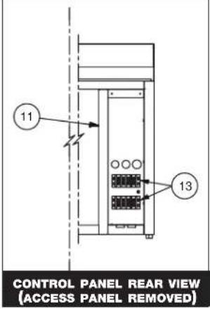
| MoDEI > | ED2(sYs)-48 ED2(sYs)-72 ED2(sYs)-96 | |||||||
| ItEM | DEsCrlPtion | Part no. | Qty | Part no. | Qty | Part no. | Qty | |
| 1 PANEL, BASE 1001859 1 1001860 1 1001861 1 | ||||||||
| 2 FILLER, UPPER, REAR 1001862 1 1001863 1 1001864 1 | ||||||||
| 3 FRAME WELD FR-26725 1 FR-26726 1 FR-26727 | 1 | |||||||
| 4 END PANEL, RH BLACK | 1001852 | 1 | 1001852 | 1 1001852 1 | ||||
| STAINLESS STEEL | 1002055 | 1 | 1002055 | 1 | 1002055 | |||
| CUSTOM COLOR | 1002050 | 1 | 1002050 | 1 | 1002050 | |||
| 5 BRACKET, MOUNTING, LEG | 1001915 | 2 | 1001915 | 2 1001915 | 915 2 | |||
| 6 FRONT PANEL BLACK | 1001854 | 1 | 1001855 | 1 | 1001856 1 | |||
| STAINLESS STEEL | 1002057 | 1 | 1002056 | 1 | 1002059 | |||
| CUSTOM COLOR | 1002052 | 1 | 1002053 | 1 | 1002679 | |||
| 7 | BUMPER, RAIL | 4ft (1.22m) | 1010952 | 1 | — | — | — | |
| 6ft (1.83m) | — | — | 1010953 | 1 | — | |||
| 8ft (2.44m) | — | — | — | — | 1010954 | |||
| 8 | BUMPER, END CAP | BM-29064 | 2 | BM-29064 | 2 | BM-29064 | ||
| 9 BUMPER, TRACK | 1010949 | 1 | 1010950 | 1 1010951 1 | ||||
| 10 | END PANEL, LH BLACK | 1001853 | 1 | 1001853 | 1 | 1001853 1 | ||
| STAINLESS STEEL | 1002056 | 1 | 1002056 | 1 | 1002056 | |||
| CUSTOM COLOR | 1002051 | 1 | 1002051 | 1 | 1002051 | |||
| 11 | CONTROL PANEL SPOT ASSEMBLY | 5001211 | 1 | 5001211 | 1 | 5001211 1 | ||
| 12 | ACCESS PANEL | 1001858 | 1 | 1001858 | 1 | 1001858 1 | ||
| 13 | TERMINAL BLOCK | BK-3023 | 2 | BK-3023 | 2 | BK-3023 2 | ||
Part numbers and drawings are subject to change without notice.
InnEr toP assEMBIY (ED2-96 sHown)

SERVICE HINGE KIT (HG-28160)
| Item | D | Es | Crl | Ptlon | QtY | |
| 1 25° | HINGE 2 7 MOUNTING BLOCKS 2 | |||||
| 2 GAS RAM PINS 2 8 HOLE PLUG 2 | ||||||
| 3 HINGE PIN 1 9 HINGE BOLT 2 | ||||||
| 4 PIN PLUG 6 10 LOCK WASHERS | 2 | |||||
| 5 LOWER GAS RAM PIN 1 11 GAS RAM HOLDEF | 2 | |||||
| 6 MOUNTING PIN 1 | ||||||
| * NOT SHOWN MoDEI > | ED2(sYs)-48 | ED2(sYs)-72 | ED2(sYs)-96 | ||||
| Item | DEsCrlPtion | Part no. | Qty | Part no. | Qty | Part no. | Qty |
| 1 | CAP, END, RH | CP-27561 | 1 | CP-27561 | 1 | CP-27561 | 1 |
| 2 | UPPER DOOR FILLER | 1005031 | 1 | 1005032 | 1 | 1005034 | 1 |
| 3 | SERVICE HINGE KIT (SEE INSET) | HG-28160 | 1 | HG-28160 | 1 | HG-28160 | 1 |
| 4 | LAMP RECEPTACLE 120V/208-240V | RP-3952 | 6 | RP-3952 | 10 | RP-3952 | 14 |
| LAMP RECEPTACLE 230V | RP-3955 | 6 | RP-3955 | 10 | RP-3955 | 14 | |
| 5 | INNER TOP | 1005017 | 1 | 1005018 | 1 | 1005024 | 2 |
| 6 | OUTER TOP | 5004030 | 1 | 5004031 | 1 | 5004034 | 1 |
| 7 | CAP, END, LH | CP-27560 | 1 | CP-27560 | 1 | CP-27560 | 1 |
| 8 | CLAMP ASSEMBLY | CM-26765 | 1 | CM-26766 | 1 | CM-26767 | 1 |
| 9* | TOP TRACK | TK-26752 | 1 | TK-26754 | 1 | TK-26756 | 1 |
| 10* | STRUT 400N | SU-26849 | 2 | — | — | SU-26849 | 4 |
| 600N | — | — | SU-26850 | 2 | — | — | |
Part numbers and drawings are subject to change without notice.
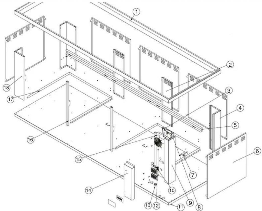
Full assEMBIY (Bu2-96 sHown)

| MoDEI > | Bu2-48 | Bu2-72 Bu2-96 | |||||
| ItEM D | EsCrlPtion Part no. QtY | Part no. QtY | Part no. QtY | ||||
| 1 TOP | FRAME 1006862 1 1006863 1 1006864 1 | ||||||
| 2 CENTER PANEL — — 1006869 1 1006875 2 | |||||||
| 3 | CORD FOR 4" BOX FAN | CD-33338 | 1 | CD-33338 | 1 | CD-33338 | 1 |
| 4 CORNER PANELS | CUSTOMER SIDE | 1006794 | 2 | 1006794 | 2 | 1006794 | 2 |
| 5 REAR SHELF SUPPORT | 1007017 1 1007018 1 1007019 1 | ||||||
| 6 SIDE & REAR BLACK PANELS | 1006857 2 1006857 4 1006857 5 | ||||||
| REAR PANEL ONLY | 1006854* | 1 | — | — | — | — | |
| 7 | CORD 6ft (1,83m) | CD-3607 | 1 | — | — | — | — |
| 12ft (3,66m) | — | — | CD-3607 | 1 | CD-3607 | 1 | |
| 8 | FAN HOUSING | FA-3568 | 1 | FA-3568 | 1 | FA-3568 | 1 |
| 9 MULLION SPOT | 1006795 1 1006870 1 5005506 1 | ||||||
| 10 | 3/4" CORD CONNECTOR | CR-3293 | 1 | CR-3293 | 1 | CR-3293 | 1 |
| 11 | BASE SPOT | 5005544 1 5005545 1 | 5005546 1 | ||||
| 12 | TERMINAL BLOCK | BK-3023 2 BK-3023 2 | BK-3023 2 | ||||
| 13 | 1-1/8" SNAP BUSHING | BU-3378 | 2 | BU-3378 | 2 | BU-3378 | 2 |
| 14 | MULLION COVER | 1006796 1 1006796 1 | 1006796 1 | ||||
| 15 | FAN GUARD | GD-2396 | 2 | GD-2396 | 2 | GD-2396 | 2 |
| 16 | POST CENTER FRONT | — | — | — | — | 1006890 | 2 |
| 17 | GUIDE RAIL | 1006830 | 1 | 1006830 | 2 | 1006830 | 2 |
| 18 | CORNER PANELS OPERATOR SIDE | 1006792 1 1006792 1 | 1006792 1 | ||||
Part numbers and drawings are subject to change without notice.
Full assEMBIY (Bu2-96 sHort sHown)
| MoDEI > | Bu2-48 sHort Bu2-712 sHort Bu2-96 sHort | ||||||
| ItEM | DEsCrIPtion | Part no. | Qty | Part no. | Qty | Part no. | Qty |
| 1 TOP | FRAME 1006862 1 1006863 1 1006864 1 | ||||||
| 2 CENTER PANEL — — 1006986 1 1006987 2 | |||||||
| 3 | CORD FOR 4" BOX FAN | CD-33338 | 1 | CD-33338 | 1 | CD-33338 | 1 |
| 4 CORNER PANELS | CUSTOMER SIDE | 1006988 | 2 | 1006988 | 2 | 1006988 | 2 |
| 5 REAR SHELF SUPPORT | 1007017 1 1007018 1 1007019 1 | ||||||
| 6 SIDE & REAR BLACK PANELS | 1006982 2 1006982 4 1006982 5 | ||||||
| REAR PANEL ONLY | 1006979* | 1 | — | — | — | — | |
| 7 | CORD 6ft (1,83m) | CD-3607 | 1 | — | — | — | — |
| 12ft (3,66m) | — | — | CD-3607 | 1 | CD-3607 | 1 | |
| 8 | FAN HOUSING | FA-3568 | 1 | FA-3568 | 1 | FA-3568 | 1 |
| 9 MULLION SPOT | 1006990 1 1006991 1 5005506 1 | ||||||
| 10 | 3/4" CORD CONNECTOR | CR-3293 | 1 | CR-3293 | 1 | CR-3293 | 1 |
| 11 | BASE SPOT | 5005544 1 5005545 1 | 5005546 1 | ||||
| 12 | TERMINAL BLOCK | BK-3023 2 BK-3023 2 | BK-3023 2 | ||||
| 13 | 1-1/8" SNAP BUSHING | BU-3378 | 2 | BU-3378 | 2 | BU-3378 | 2 |
| 14 | MULLION COVER | 1006978 1 1006978 1 | 1006796 1 | ||||
| 15 | FAN GUARD | GD-2396 | 2 | GD-2396 | 2 | GD-2396 | 2 |
| 16 | POST CENTER FRONT | — | — | — | — | 1006890 | 2 |
| 17 | GUIDE RAIL | 1006830 | 1 | 1006830 | 2 | 1006830 | 2 |
| 18 | CORNER PANELS OPERATOR SIDE | 1006989 1 1006989 1 | 1006792 1 | ||||
Part numbers and drawings are subject to change without notice.




![ED2-48 120/208-240V, 5D/60Hz, 14.0A, 3350V 12/4 AVG CORD TOP T-BLOCK POWER IN 120/208-240V - 1PH 3350V 14.0A - 60Hz FAN, 230V (FA-3568) MOUNTED IN CART FAN CORD (CD-33338) TOP T-BLOCK L+ N L+ G 6' 12/3 CORD [CD-3607] BOTTOM T-BLOCK POWER IN CART WATTAGE VERSIE DUE TO DIFFERENT UNIT COMBINATIONS. FOR…](/content/2026/07/1491265/images/ab77dea88927bef17fc1b51c394346145f25801bcd0f618c1e680d79821af41f.jpg)
![FAN, 230V (FA-3568) MOUNTED IN CART FAN CORD (CD-33338) ED2-72 120/208-240V, 50/60Hz, 20.0A, 4800V 10/4 AWG CORD 6' 12/3 CORD [CD-3607] TOP T-BLOCK POWER IN 120/208-240V - 1PH 4800V 20.0A - 60Hz 750-S 120V, 8.6A, 1040W WIRING DIAGRAM A-758I or 208V, 3.7A, 789W 246V, 4.3A, 1940W WIRING DIAGRAM A-7613…](/content/2026/07/1491265/images/0b98f4894739df59355882e61e67f8e37d3790149a444c9714f075fdab3c0dcd.jpg)
![ED2-96 120/208-240V, 50/60Hz, 24.0A, 5300W 10/4 AWG CORD FAN, 230V (FA-3568) MOUNTED IN CART FAN CORD (CD-33338) 6' 12/3 CORD [CD-3607] TOP T-BLOCK POWER IN 120/208-240V - IPH 5300V 24.0A - 50Hz TOP T-BLOCK L1 N L2 G 6' 12/3 CORD [CD-3607] 750-S 120V, 8.6A, 1640V VIRING DIAGRAM A-758I or 208V, 3.7A,…](/content/2026/07/1491265/images/0b95bd53490a9025f359c2a431af237219d1f3337d85d7402ebae5b135532a75.jpg)
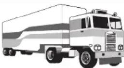
All Alto-Shaam equipment is sold F.O.B. shipping point, and when accepted by the carrier, such shipments become the property of the consignee.
Should damage occur in shipment, it is a matter between the carrier and the consignee. In such cases, the carrier is assumed to be responsible for the safe delivery of the merchandise, unless negligence can be established on the part of the shipper.
- Make an immediate inspection while the equipment is still in the truck or immediately after it is moved to the receiving area.
Do not wait until after the material is moved to a storage area. - Do not sign a delivery receipt or a freight bill until you have made a proper count and inspection of all merchandise received.
- Note all damage to packages directly on the carrier's delivery receipt.
- Make certain the driver signs this receipt. If he refuses to sign, make a notation of this refusal on the receipt.
- If the driver refuses to allow inspection, write the following on the delivery receipt:
Driver refuses to allow inspection of containers for visible damage. - Telephone the carrier's office immediately upon finding damage, and request an inspection. Mail a written confirmation of the time, date, and the person called.
- Save any packages and packing material for further inspection by the carrier.
- Promptly file a written claim with the carrier and attach copies of all supporting paperwork.
We will continue our policy of assisting our customers in collecting claims which have been properly filed and actively pursued. We cannot, however, file any damage claims for you, assume the responsibility of any claims, or accept deductions in payment for such claims.
LIMITED WARRANTY
Alto-Shaam, Inc. warrants to the original purchaser only that any original part that is found to be defective in material or workmanship will, at Alto-Shaam's option, subject to provisions hereinafter stated, be replaced with a new or rebuilt part.
The parts warranty period is as follows:
For the refrigeration compressor on Alto-Shaam Quickchillers ™ , five (5) years from the date of installation.
For the heating element on Halo Heat ® cook/hold ovens, as long as the original purchaser owns the oven.
For all other parts, one (1) year from the date of installation or fifteen (15) months from the shipping date, whichever occurs first.
The labor warranty period is one (1) year from the date of installation or fifteen (15) months from the shipping date, whichever occurs first.
Alto-Shaam will bear normal labor charges performed during standard business hours, excluding overtime, holiday rates or any additional fees.
To be valid, a warranty claim must be asserted during the applicable warranty period. This warranty is not transferable.
THIS WARRANTY DOES NOT APPLY TO:
- Calibration.
- Replacement of light bulbs, door gaskets, and/or the replacement of glass due to damage of any kind.
- Equipment damage caused by accident, shipping, improper installation or alteration.
- Equipment used under conditions of abuse, misuse, carelessness or abnormal conditions, including but not limited to, equipment subjected to harsh or inappropriate chemicals, including but not limited to, compounds containing chloride or quaternary salts, poor water quality, or equipment with missing or altered serial numbers.
- Damage incurred as a direct result of poor water quality, inadequate maintenance of steam generators and/or surfaces affected by water quality. Water quality and required maintenance of steam generating equipment is the responsibility of the owner/operator.
- Damage caused by use of any cleaning agent other than Alto-Shaam's Combitherm ® Cleaner, including but not limited to damage due to chlorine or other harmful chemicals. Use of Alto-Shaam's Combitherm ® Cleaner on Combitherm ® ovens is highly recommended.
- Any losses or damage resulting from malfunction, including loss of product or consequential or incidental damages of any kind.
- Equipment modified in any manner from original model, substitution of parts other than factory authorized parts, removal of any parts including legs, or addition of any parts.
This warranty is exclusive and is in lieu of all other warranties, express or implied, including the implied warranties of merchantability and fitness for a particular purpose. In no event shall Alto-Shaam be liable for loss of use, loss of revenue or profit, or loss of product, or for any indirect, special, incidental, or consequential damages. No person except an officer of Alto-Shaam, Inc. is authorized to modify this warranty or to incur on behalf of Alto-Shaam any other obligation or liability in connection with Alto-Shaam equipment.

Effective 09/10
RECORD THE MODEL AND SERIAL NUMBER OF THE APPLIANCE FOR EASY REFERENCE.
ALWAYS REFER TO BOTH MODEL AND SERIAL NUMBER IN ANY CONTACT WITH ALTO-SHAAM REGARDING THIS APPLIANCE.
Model:
Date Installed:
Voltage:
Purchased From:
Serial Number:
W164 N9221 Water Street · P.O. Box 450 · Menomonee Falls, Wisconsin 53052-0450 · U.S.A.
PHONE:
262.251.3800
• 800.558-8744
USA/CANADA
FAX:
262.251.7067 • 800.329.8744
U.S.A. ONLY
www.alto-shaam.com
PRINTED IN U.S.A.
- HEATED DISPLAY CASES
- FULL SERVICE OR SELF SERVICE
- MODELS
- ALTO-SHAAM®
- INSTALLATION3
- OPERATING INSTRUCTIONS
- CARE AND CLEANING
- SERVICE
- WIRE DIAGRAMS
- WARRANTY
- DEIVERY
- UNPACKING
- SAFETY PROCEDURES AND PRECAUTLONS
- DANGER
- WARNING
- CAUTION
- CAUTLON
- NOTE
- SITE INSTALLATION
- MINIMUM CLEARANCE REQUIREMENTS
- LEVELING
- CUTTING BOARD INSTALLATION
- INSTALLATION
- SLTE INSTALLATION
- ELECTRICAL CONNECTION
- REGARDING INTERNATIONAI STANDARD UNITS
- HARD WIRED MODELS
- USER SAFETY INFORMATLON
- START-UP OPERATION
- BEFORE INITIAL USE
- PREHEATING
- OPERATING PROCEDURES
- DO NOT ADD WATER TO DISPLAY CASE
- PLACE DIVIDERS AND SERVING PANS IN CASE
- TURN DISPLAY IIGHTS "ON" AND SET THE THERMOSTAT(S) AT NUMBER "10" TO PREHEAT
- IOAD HOT FOODS INTO DISPLAY CASE
- RESET THERMOSTAT(S) AS NEEDED
- PLACEMENT OF FOOD PROBE
- SERVE FRESH HOT FOOD
- INTERNATIONAL PAN DIVIDER KITS
- GENERAL HOLDING GUIDEINES
- CIEANING AND PREVENTIVE MAINTENANCE
- PROTECTING STAINIESS STEEI SURFACES
- CIEANING AGENTS
- CIEANING MATERLALS
- CARE AND CIEANING
- EQUIPMENT CARE
- CIEAN THE PROBES DALIY
- CIEAN DALIY
- CHECK OVERALL CONDLTLON ONCE A MONTH
- DO NOT USE APPILANCE IF CONTROLS ARE NOT PROPERIY FUNCTLONING
- CABIE REPLACEMENT KITS
- 48 SERIES
- CABLE REPLACEMENT KIT
- 72 SERIES
- 96 SERIES
- FULL ASSEMBLY • FRONT VIEW (ED2-96 SHOWN)
- INNER TOP ASSEMBIY (ED2-96 SHOWN)
- LIMITED WARRANTY
- THE PARTS WARRANTY PERIOD IS AS FOLLOWS
- THIS WARRANTY DOES NOT APPLY TO
Brand : Alto-Shaam
Model : EU2SYS-96
Category : Food Warmer