USER MANUAL RSJ-15/190RDN7-L2 MIDEA
ALL IN ONE Type Air-source Heat Pump Water Heater
USER MANUAL
MODEL NUMBER:
RSJ-15/190RDN7-L2
RSJ-23/300RDN7-L2

Warning notices: Before using this product, please read this manual carefully and keep it for future reference. The design and specifications are subject to change without prior notice for product improvement.
Consult with your dealer or manufacturer for details.
The diagram above is just for reference. Please take the appearance of the actual product as the standard.
THANK YOU LETTER
Thank you for choosing Midea! Before using your new Midea product, please read this manual thoroughly to ensure that you know how to operate the features and functions that your new appliance offers in a safe way.
CONTENTS
THANK YOU LETTER 01
SAFETY INSTRUCTIONS 02
SPECIFICATIONS 14
PRODUCT OVERVIEW 15
BASIC OPERATION PRINCIPLE 16
BEFORE INSTALLATION 17
INSTALLATION 20
TRIAL-RUNNING 25
OPERATION 30
MAINTENANCE 35
TROUBLE SHOOTING 36
HEAT PUMP MANUFACTUR-ER'S WARRANTY 39
TRADEMARKS, COPYRIGHTS AND LEGAL STATEMENT 41
DISPOSAL AND RECYCLING 41
DATA PROTECTION NOTICE 42
SAFETY PRECAUTIONS
It's really important you read Safety Precautions Before Operation and Installation Incorrect installation due to ignoring instructions can cause serious damage or injury. The seriousness of potential damage or injuries is classified as either a WARNING or CAUTION.
Please read thoroughly all of the instrucitons before installing or operating the unit. Following safety symbol is very important, always read and obey all safety symbol:

WARNING
The signal word indicates a hazard with a medium level of risk which, if not avoided, may result in death or serious injury.

CAUTION
The signal word indicates a hazard with a low degree of risk which, if not avoided, may result in minor or moderate injury.

DANGER
You may be killed or seriously injured immediately if you don't obey instructions.
Read these operating instructions carefully and attentively before using/commissioning the unit and keep them in the immediate vicinity of the installation site or unit for later use!

WARNING
- This appliance can be used by children aged from 8 years and above and persons with reduced physical, sensory or mental capabilities or lack of experience and knowledge if they have been given supervision or instruction concerning use of the appliance in a safe way and understand the hazards involved. Children shall not play with the appliance. Cleaning and user maintenance shall not be made by children without supervision.
- This appliance is not intended for use by persons (including children) with reduced physical, sensory or mental capabilities, or lack of experience and knowledge, unless they have been given supervision or instruction concerning use of the appliance by a person responsible for their safety. Children should be supervised to ensure that they do not play with the appliance.
- This unit is required reliable earthing before usage, otherwise might cause injury or death.
If you can't make sure that your house power supply is earthed well, please don't install the unit. The unit must be installed by a licensed tradesperson and in accordance with:

- Midea installation instructions.
- AS/NZS 3500.4-"National Plumbing and Drainage Code Hot Water Supply Systems-Acceptable Solutions".
• AS/NZS 3000-Wiring Rules.
- Local authority regulations.
• Buliding Codes of Australia
- Local Occupational Health and Safety (OH&S) Regulations.

NOTE
This water heater must be installed by a licensed person as required by the Building Act. Only a licensed person will give you a compliance certificate, showing that the work complies with all the relevant standards and only a licensed person will have insurance protecting their workmanship for 6 years. Installation shall conform to the Plumbing Code of Australia (PCA).

WARNING
FOR CONTINUED SAFETY OF THIS APPLIANCE IT MUST BE INSTALLED, OPERATED AND MAINTAINED IN ACCORDANCE WITH THE MANUFACTURER'S INSTRUCTIONS.
THIS APPLIANCE MAY DELIVER WATER AT HIGH TEMPERATURE. REFER TO THE PLUMBING CODE OF AUSTRALIA (PCA), LOCAL REQUIREMENTS AND INSTALLATION INSTRUCTIONS TO DETERMINE IF ADDITIONAL DELIVERY TEMPERATURE CONTROL IS REQUIRED.
DO NOT USE MEANS TO ACCELERATE THE DEFROSTING PROCESS OR TO CLEAN, OTHER THAN THOSE RECOMMENDED BY THE MANUFACTURER. THE APPLIANCE SHALL BE STORED IN A ROOM WITHOUT CONTINUOUSLY OPERATING IGNITION SOURCES (FOR EXAMPLE: OPEN FLAMES, AN OPERATING GAS APPLIANCE OR AN OPERATING ELECTRIC HEATER. DO NOT PIERCE OR BURN.
BE AWARE THAT REFRIGERANTS MAY NOT CONTAIN AN ODOUR.

BATTERY WARNING

WARNING:
Contains button or coin cell battery.
- WARNING: The battery is hazards and KEEP OUT OF REACH OF CHILDREN (Whether the battery is new or used).
- If the battery compartment(if applicable) does not close securely, stop using the product and keep it away from children.
For appliances which contain coin or lithium batteries:

BATTERY WARNING
KEEP OUT OF REACH OF CHILDREN.
Swallowing can lead to chemical burns, perforation of soft tissue, and death. Severe burns can occur within 2 hours of ingestion. Seek medical attention immediately.

For appliances which contain button or non-lithium batteries.
- The battery can cause serious injuries if it is swallowed or placed inside any part of the body.
- If you think batteries might have swallowed or placed inside any part of the body, seek immediate medical attention.

BATTERY NOTES
If it is suspected a button/coin battery has been swallowed or otherwise placed inside any part of the body, a person should contact the Australian Poisons Information Centre on 13 11 26 immediately for 24/7fast, expert advice.

BATTERY DISPOSAL
- Dispose of used button/coin batteries immediately.
- Place sticky tape around both sides of the battery and dispose of it immediately in an outside bin, out of reach of children, or recycle safely.
Warning - Hot water burns. As a safety precaution, young children should always be supervised around hot water fixtures.
Heat pump water heaters can store water at temperatures that can cause scalding. Water temperatures over 50° C can scald and care needs to be taken to ensure that injuries do not occur through incorrect use of your water heater.
As heat pump water heaters can generate water temperatures in excess of 60° C, regulations require that a tempering valve be fitted to the heater to prevent water temperatures going to the home exceeding a preset safe maximum. The tempering valve must be connected to the hot water outlet line from the water heater. The valve must be fitted by an authorized plumber at the time of installation or in retro fitting to existing systems.
Care should be taken to avoid coming into contact with any pipe work or fixtures associated with the water heater pipe lines. Under NO circumstances should any 'home handy man' type modifications be attempted.
- This appliance is not intended for use by persons (including children) with reduced physical sensory or mental capabilities, or lack of experience and knowledge, that prevents them from using the appliance safely without supervision or instruction. Children should be supervised by a responsible person for their safety to ensure that they do not play with the appliance.
- DANGER: Failure to operate the relief valve easing gear at least once every six months may result in the water heater exploding. Continuous leakage of water from the valve may indicate a problem with the water heater.
- THE INSTALLATION MUST COMPLY WITH THE REQUIREMENTS OF AS/NZS 3500.4, AS/NZS 3000, and all local codes and regulatory authority requirements. In New Zealand, the installation must conform to the New Zealand Building Code G12.
The power supply must be protected by an individual circuit breaker at the main electrical supply switchboard and rated to suit the booster size. The supply to the heat pump water heater can be operated directly from the switchboard or via a remotely mounted switch or time clock as requested by the customer. The heater must be provided with a suitable means for disconnecting the power supply.
DANGER: The operation of the thermal cut-out indicates a possibly dangerous situation. Do not reset the thermal cut-out until the water heater has been serviced by a qualified person.
Appliance is intended to be permanently connected to the water mains and not connected by a hose-set.
Hose-set is not to be used for connection to water mains.
The Heat Pump Water Heater is for outdoor use only.
EXPLANATION OF SYMBOLS DISPLAYED ON THE INDOOR UNIT OR OUTDOOR UNIT
 | WARNING | This symbol shows that this appliance used a flammable refrigerant. If the refrigerant is leaked and exposed to an external ignition source, there is a risk of fire. |
 | CAUTION | This symbol shows that the operation manual should be read carefully. |
 | CAUTION | This symbol shows that a service personnel should be handling this equipment with reference to the installation manual. |
 | CAUTION |
 | CAUTION | This symbol shows that information is available such as the operating manual or installation manual. |
-
Installation (Space)
-
That the installation of pipe-work shall be kept to a minimum.
- That pipe-work shall be protected from physical damage. In the case of flammable
refrigerants, shall not be installed in an unventilated space.
- Any person who is involved with working on or breaking into a refrigerant circuit should hold a current valid certificate from an industry-accredited assessment authority, which authorises their competence to handle refrigerants safely in accordance with an industry recognised assessment specification.
- Maintenance and repair requiring the assistance of other skilled personnel shall be carried out under the supervision of the person competent in the use of flammable refrigerants.
- Do not use means to accelerate the defrosting process or to clean, other than those recommended by the manufacturer.
- The appliance shall be stored in a room without continuously operating ignition sources (for example: open flames, an operating gas appliance or an operating electric heater).
- Be more careful that foreign matter (oil, water, etc) does not enter the piping. Also, when storing the piping, securely seal the opening by pinching, taping, etc.
- Do not pierce or burn.
- Be aware that refrigerants may not contain an odour.
- All working procedure that affects safety means shall only be carried by competent persons.
- Appliance shall be stored in a well -ventilated area where the room size corresponds to the room area as specific for operation.
- The appliance shall be stored so as to prevent mechanical damage from occurring.
-
Joints shall be tested with detection equipment with a capability of 5 g/year of refrigerant or better, with the equipment in standstill and under operation or under a pressure of at least these standstill or operation conditions after installation. Detachable joints shall NOT be used in the indoor side of the unit (brazed, welded joint could be used).
-
When a FLAMMABLE REFRIGERANT is used, the requirements for installation space of appliance and/or ventilation requirements are determined according to
-- the mass charge amount (M) used in the appliance,
-- the installation location,
-- the type of ventilation of the location or of the appliance.
-
servicing shall be performed only as recommended by the manufacturer.
-
Unventilated areas
-For appliances containing flammable refrigerants is installed in an unventilated area, please make sure that it will not stagnate so as to create a fire or explosion hazard for any refrigerant leak.
- Qualification of workers
The manual shall contain specific information about the required qualification of the working personnel for maintenance, service and repair operations. Every working procedure that affects safety means shall only be carried out by competent persons:
Examples for such working procedures are:
breaking into the refrigerating circuit;
opening of sealed components;
opening of ventilated enclosures.
- Checks to the area
Prior to beginning work on systems containing flammable refrigerants, safety checks are necessary to ensure that the risk of ignition is minimised. For repair to the refrigerating system, the following precautions shall be complied with prior to conducting work on the system.
- Work procedure
Works shall be undertaken under a controlled procedure so as to minimise the risk of a flammable gas or vapour being present while the work is being performed.
- General work area
All maintenance staff and others working in the local area shall be instructed on the nature of work being carried out. work in confined sapces shall be avoided. The area around the workspace shall be sectioned off. Ensure that the conditions within the area have been made safe by control of flammable material.
- Checking for presence of refrigerant
The area shall be checked with an appropriate refrigerant detector prior to and during work, to ensure the technician is aware of potentially flammable atmospheres. Ensure that the leak detection equipment being used is suitable for use with flammable refrigerants, i.e. no sparking, adequately sealed or intrinsically safe.
- Presence of fire extinguisher
If any hot work is to be conducted on the refrigeration equipment or any associated parts, appropriate fire extinguishing equipment shall be available to hand. Have a dry power or CO2 fire extinguisher adjacent to the charging area.
- No ignition sources
No person carrying out work in relation to a REFRIGERATING SYSTEM which involves exposing any pipe work shall use any sources of ignition in such a manner that it may lead to the risk of fire or explosion. All possible ignition sources, including cigarette smoking, should be kept sufficiently far away from the site of installation, repairing, removing and disposal, during which refrigerant can possibly be released to the surrounding space. Prior to work taking place, the area around the equipment is to be surveyed to make sure that there are no flammable hazards or ignition risks. "No Smoking" signs shall be displayed.
7. Ventilated area
Ensure that the area is in the open or that it it adequately ventilated before breaking into the system or conducting any hot work. A degree of ventilation shall continue during the period that the work is carried out. The ventilation should safely disperse any released refrigerant and preferably expel it externally into the atmosphere.
8. Checks to the refrigeration equipment
Where electrical components are being changed, they shall be fit for the purpose and to the correct specification. At all times the manufacturer's maintenance and service guidelines shall be followed. If in doubt consult the manufacturer's technical department for assistance. The following checks shall be applied to installations using FLAMMABLE REFRIGERANTS:
- the actual refrigerant charge is in accordance with the room size within which the refrigerant containing parts are installed;
- the ventilation machinery and outlets are operating adequately and are not obstructed;
- if an indirect refrigerating circuit is being used, the secondary circuits shall be checked for the presence of refrigerant;
- marking to the equipment continues to be visible and legible, marking and signs that are illegible shall be corrected;
- refrigeration pipe or components are installed in a position where they are unlikely to be exposed to any substance which may corrode refrigerant containing components, unless the components are constructed of materials which are inherently resistant to being corroded or are suitably protected against being so corroded.
9. Checks to electrical devices
Repair and maintenance to electrical components shall include initial safety checks and component inspection procedures. If a fault exists that could compromise safety, then no electrical supply shall be connected to the circuit until it is satisfactorily dealt with. If the fault cannot be corrected immediately but it is necessary to continue operation, and adequate temporary solution shall be used. This shall be reported to the owner of the equipment so all parties are advised. Initial safety checks shall include:
- that capacitors are discharged: this shall be done in a safe manner to avoid possibility of sparking
- that there no live electrical components and wiring are exposed while charging, recovering or purging the system;
• that there is continuity of earth bonding.
10. Repairs to sealed components
- During repairs to sealed components, all electrical supplies shall be disconnected from the equipment being worked upon prior to any removal of sealed covers, etc. If it is absolutely necessary to have an electrical supply to equipment during servicing, then a permanently operating form of leak detection shall be located at the most critical point to warn of a potentially hazardous situation.
- Particular attention shall be paid to the following to ensure that by working on electrical components, the casing is not altered in such a way that the level of protection is affected. This shall include damage to cables, excessive number of connections, terminals not made to original specification, damage to seals, incorrect fitting of glands, etc.
- Ensure that the apparatus is mounted securely.
-
Ensure that seals or sealing materials have not degraded to the point that they no longer serve the purpose of preventing the ingress of flammable atmospheres. Replacement parts shall be in accordance with the manufacturer's specifications.
-
Repair to intrinsically safe components
-
Do not apply any permanent inductive or capacitance loads to the circuit without ensuring that this will not exceed the permissible voltage and current permitted for the equipment in use.
- Intrinsically safe components are the only types that can be worked on while live in the presence of a flammable atmosphere. The test apparatus shall be at the correct rating.
- Replace components only with parts specified by the manufacturer. Other parts may result in the ignition of refrigerant in the atmosphere from a leak.
NOTE The use of silicon sealant can inhibit the effectiveness of some types of leak detection equipment. Intrinsically safe components do not have to be isolated prior to working on them.
- Cabling
Check that cabling will not be subject to wear, corrosion, excessive pressure, vibration, sharp edges or any other adverse environmental effects. The check shall also take into account the effects of aging or continual vibration from sources such as compressors or fans.
- Detection of flammable refrigerants
Under no circumstances shall potential sources of ignition be used in the searching for or detection of refrigerant leaks. A halide torch (or any other detector using a naked flame) shall not be used.
The following leak detection methods are deemed acceptable for refrigerant systems. Electronic leak detectors may be used to detect refrigerant leaks but, in the case of FLAMMABLE REFRIGERANTS, the sensitivity may not be adequate, or may need re-calibration. (Detection equipment shall be calibrated in a refrigerant-free area.) Ensure that the detector is not a potential source of ignition and is suitable for the refrigerant used. Leak detection equipment shall be set at a percentage of the LFL of the refrigerant and shall be calibrated to the refrigerant employed, and the appropriate percentage of gas (25 % maximum) is confirmed.
Leak detection fluids are also suitable for use with most refrigerants but the use of detergents containing chlorine shall be avoided as the chlorine may react with the refrigerant and corrode the copper pipe-work.
NOTE Examples of leak detection fluids are
- bubble method,
- fluorescent method agents.
If a leak is suspected, all naked flames shall be removed/extinguished.
If a leakage of refrigerant is found which requires brazing, all of the refrigerant shall be recovered from the system, or isolated (by means of shut off valves) in a part of the system remote from the leak. For appliances containing flammable refrigerants, oxygen free nitrogen (OFN) shall then be purged through the system both before and during the brazing processSee the following instructions of removal of refrigerant.
- Removal and evacuation
When breaking into the refrigerant circuit to make repairs - or for any other purpose conventional procedures shall be used. However, for flammable refrigerants it is important that best practice be followed, since flammability is a consideration.
The following procedure shall be adhered to:
- remove refrigerant ;
• purge the circuit with inert gas (optional for A2L);
• evacuate (optional for A2L);
• purge the with inert gas (optional for A2L);
- open the circuit by cutting or brazing.
The refrigerant charge shall be recovered into the correct recovery cylinders. For appliances containing flammable refrigerants other than A2L refrigerants, the system shall be purged with oxygen-free nitrogen to render the appliance safe for flammable refrigerants. This process may need to be repeated several times.
Compressed air or oxygen shall not be used for purging refrigerant systems.
For appliances containing flammable refrigerants, other than A2L refrigerants, refrigerants purging shall be achieved by breaking the vacuum in the system with oxygen-free nitrogen and continuing to fill until the working pressure is achieved, then venting to atmosphere, and finally pulling down to a vacuum. This process shall be repeated until no refrigerant is within the system. When the final oxygen-free nitrogen charge is used, the system shall be vented down to atmospheric pressure to enable work to take place. This operation is absolutely vital if brazing operations on the pipe-work are to take place.
Ensure that the outlet for the vacuum pump is not close to any potential ignition sources and that ventilation is available.
NOTE: A2L refrigerants: Such as R32, R454B refrigerant.
15. Charging procedures
In addition to conventional charging procedures, the following requirements shall be followed:
- Ensure that contamination of different refrigerants does not occur when using charging equipment. Hoses or lines shall be as short as possible to minimise the amount of refrigerant contained in them.
- Cylinders shall be kept in an appropriate position according to the instructions.
- Ensure that the refrigerating system is earthed prior to charging the system with refrigerant.
- Label the system when charging is complete (if not already labelled).
- Extreme care shall be taken not to overfill the refrigerating system.
Prior to recharging the system, it shall be pressure-tested with the appropriate purging gas. The system shall be leak-tested on completion of charging but prior to commissioning. A follow up leak test shall be carried out prior to leaving the site.
16. Decommissioning
Before carrying out this procedure, it is essential that the technician is completely familiar with the equipment and all its detail. It is recommended good practice that all refrigerants are recovered safely. Prior to the task being carried out, an oil and refrigerant sample shall be taken in case analysis is required prior to re-use of recovered refrigerant. It is essential that electrical power is available before the task is commenced.
a) Become familiar with the equipment and its operation.
b) Isolate system electrically.
c) Before attempting the procedure ensure that:
- mechanical handling equipment is available, if required, for handling refrigerant cylinders;
- all personal protective equipment is available and being used correctly;
- the recovery process is supervised at all times by a competent person;
- recovery equipment and cylinders conform to the appropriate standards.
d) Pump down refrigerant system, if possible.
e) If a vacuum is not possible, make a manifold so that refrigerant can be removed from various parts of the system.
f) Make sure that cylinder is situated on the scales before recovery takes place.
g) Start the recovery machine and operate in accordance with instructions.
h) Do not overfill cylinders (no more than 80 % volume liquid charge)
i) Do not exceed the maximum working pressure of the cylinder, even temporarily.
j) When the cylinders have been filled correctly and the process completed, make sure that the cylinders and the equipment are removed from site promptly and all isolation valves on the equipment are closed off.
k) Recovered refrigerant shall not be charged into another refrigerating system unless it has been cleaned and checked.
17. Labelling
Equipment shall be labelled stating that it has been de-commissioned and emptied of refrigerant. The label shall be dated and signed. For appliances containing flammable refrigerants, ensure that there are labels on the equipment stating the equipment contains flammable refrigerant.
18. Recovery
When removing refrigerant from a system, either for servicing or decommissioning, it is required to follow good practice so that all refrigerants are removed safely. When transferring refrigerant into cylinders, ensure that only appropriate refrigerant recovery cylinders are employed. Ensure that the correct number of cylinders for holding the total system charge is available. All cylinders to be used are designated for the recovered refrigerant and labelled for that refrigerant (i.e. special cylinders for the recovery of refrigerant). Cylinders shall be complete with pressure-relief valve and associated shut-off valves in good working order. Empty recovery cylinders are evacuated and, if possible, cooled before recovery occurs.
The recovery equipment shall be in good working order with a set of instructions concerning the equipment that is at hand and shall be suitable for the recovery of the flammable refrigerant. Consult manufacturer if in doubt. In addition, a set of calibrated weighing scales shall be available and in good working order. Hoses shall be complete with leak-free disconnect couplings and in good condition.
The recovered refrigerant shall be processed according to local legislation in the correct recovery cylinder, and the relevant waste transfer note arranged. Do not mix refrigerants in recovery units and especially not in cylinders.
If compressors or compressor oils are to be removed, ensure that they have been evacuated to an acceptable level to make certain that flammable refrigerant does not remain within the lubricant. The compressor body shall not be heated by an open flame or other ignition sources to accelerate this process. Draining of oil from a system shall be carried out safely.
19. Venting of HC Refrigerant (R290)
Venting may be carried out as an alternative to recovering the refrigerant. Because HC refrigerants have no ODP and negligible GWP, under certain circumstances it may be considered acceptable to vent the refrigerant. However, if this is to be considered, it should be done in accordance with the relevant national rules or regulations, if they permit.
In particular, before venting a system, it would be necessary to:
- Ensure that legislation relating to waste material has been considered
- Ensure that environmental legislation has been considered
- Ensure that legislation addressing safety of hazardous substances is satisfied
- Venting is only carried out with systems that contain a small quantity of refrigerant, typically less than 500g.
- Venting to inside a building is not permissible under any circumstances
- Venting must not be to a public area, or where people are unaware of the procedure taking place.
- The hose must be of sufficient length and diameter such that it will extend to at least 3 m beyond the outside of the building
- The venting should only take place on the certainty that the refrigerant will not get blown back into any adjacent buildings, and that it will not migrate to a location below ground level.
• The hose is made of material that is compatible for use with HC refrigerants and oil
- A device is used to raise the hose discharge at least 1 m above ground level and so that the discharge is pointed in an upwards direction (to assist with dilution).
- The end of the hose can now discharge and disperse the flammable fumes into the ambient air.
- There should not be any restriction or sharp bends within the vent-line which will hinder the ease of flow.
• There must be no sources of ignition near the hose discharge.
- The hose should be regularly checked to ensure that there are no holes or kinks in it, that could lead to leakage or blocking of the passage of flow.
When carrying out the venting, the flow of refrigerant should be metered using manifold gauges to a low flow rate, so as to ensure the refrigerant is well diluted. Once the refrigerant has ceased flowing, if possible, the system should be flushed out with OFN; if not, then the system should be pressurised with OFN and the venting procedure carried out two or more times, to ensure that there is minimal HC refrigerant remaining inside the system.
-
Transportation, marking and storage for units
-
Transport of equipment containing flammable refrigerants
Compliance with the transport regulations
- Marking of equipment using signs
Compliance with local regulations
- Disposal of equipment using flammable refrigerants
Compliance with national regulations
- Storage of equipment/appliances
The storage of the appliance should be in accordance with the applicable regulations or instructions, whichever is more stringent.
- Storage of packed (unsold) equipment
Storage package protection should be constructed such that mechanical damage to the equipment inside the package will not cause a leak of the refrigerant charge.
The maximum number of pieces of equipment permitted to be stored together will be determined by local regulations.

NOTE
Note for the minimum room area when using flammable refrigerant
- When flammable refrigerant are employed, appliance shall be stored in a well-ventilated area where the room size corresponds to the room area as specific for operation. For specific information of the refrigerant amount and the unit model, please refer to the nameplate on the unit itself. Please refer to the cooling capacity on the nameplate of the machine you purchased to match it with the corresponding minimum room area model listed below.
- Appliance shall be installed, operated and stored in a room with a floor area larger than:
<=2.6kW units: 17.33m²
2.6kW and <=3.5kW units: 25.4m²
3.5kW and <=5.2kW units: 34.67m²
5.3kW and <=7.1kW units: 47.33m²
- Reusable mechanical connectors and flared joints are not allowed indoors.
Please read thoroughly all of the instructons before installing or operating the unit. The following safety warnings are very important, always read and obey all safety symbols:
WARNING
- The unit must be earthed effectively.
- A RCD breaker must be installed adjacent to the power supply.
- Do not remove, cover or deface any permanent instructions, lables, or the data label from either the outside of the unit or inside of unit panels.
- Only qualified persons should perform the installation of this unit in accordance with local national regulations and this manual. Improper installation may result in water leakage, electric shock or fire.
- Ask qualified person for relocating, repairing and maintaining the unit. Improper installation may result in water leakage, electric shock or fire.
- Electric connection work should comply with the instructions of local power company, local electric utility and this manual.
- Never use an incorrectly fuse rated, otherwise the unit may break down and risk of electrical fire.
- Do not insert fingers, rods or other objects into the air inlet or outlet. The fan is rotating at high speed, and may cause injury.
Never use a flammable spray such as hair spray, lacquer paint near the unit. It may cause a fire.
- This appliance is not intended for use by persons (including children) with reduced physical, sensory or mental capabilities, or lack of experience and knowledge, unless they have been given supervision or instruction concerning use of the appliance by a person responsible for their safety. Children should be supervised to ensure that they do not play with the appliance.
- If the supply cord is damaged, it must be replaced by the manufacturer or its service agent or a similarly qualified person.
- DISPOSAL: Do not dispose this product as unsorted municipal waste. Collection of such waste separately for special treatment is necessary. Do not dispose of electrical appliances as unsorted municipal waste, use separate collection facilities. Contact your local government for information regarding the collection systems available.

- The water may drip from the discharge pipe of the pressure-relief device and that this pipe must be left open to the atmosphere.
- The pressure-relief device is to be operated regularly to remove lime deposits and to verify that it is not blocked.
- Danger: The operation of the thermal cut-out indicates a possibly dangerous situation. Do not reset the thermal cut-out until the water heater has been serviced by a qualified person.

CAUTION
- The earthing pole of socket must be well grounded, make sure that power supply socket and plug are dry and connected tightly.
- Before cleaning, be sure to stop the operation and turn the breaker off or pull out the power plug. Otherwise, an electric shock and injury may be caused.
- Water temperature over 50°C can cause severe burns instantly or death from scalds. Children, disabled and elderly are at highest risk of being scalded. Feel water before bathing or showering. Water temperature limiting valves are required as per AS 3500.

- Do not operate the unit with a wet hand. An electric shock may be caused.
- The installation height of power supply should be over 1.8m, if there is any water exposure, steps must be taken to separate the power supply from water.
- A one-way valve must be installed on the water inlet side, as well as an isolation value.
- It is normal for some water to be released from the PTR valve during operation. But, if there is a large volume of water, call your service agent for instructions. After long term use, check the unit base and fittings. If damaged, the unit may sink, resulting in injury. Arrange the drain pipe to ensure smooth draining. Improper drainage work may cause wetting of the building, furniture etc. Do not touch the inner parts of the controller or remove the front panel. Some parts inside are dangerous to touch, and damage may be caused.
- Do not turn off the power supply. System will stop or restart heating automatically. A continuous power supply for water heating is necessary, except service and maintenance. Hydrogen gas is extremely flammable, and may build up if no water is drawn of for several weeks. To reduce the risk of injury under these conditions, it is recommended that the hot water tap is opened for several minutes at the kitchen sink before using any electrical appliance connected to the hot water system. When hydrogen is present, there will probably be an unusual sound such as air escaping through the pipe as the water begins to flow. There should be no smoking or open flame near the tap at the time it is open.
SPECIFICATIONS
| Model | RSJ-15/190RDN7-L2 | RSJ-23/300RDN7-L2 |
| Water-heating cap. 1800W | | 2500W |
| Rated power/AMPS | 3000W/13.0A | 4250W/18.4A |
| Power supply | 220-240V~ 50Hz | 220-240V~ 50Hz |
| Operation control | Auto/Manual startup, error alarm, timer, etc |
| Protection | High-pressure Protector, Over-load Protector, Temp Controller&Protector, etc |
| E-heater power | 2150W 3250W | |
| Refrigerant | R290(0.29kg) R290(0.42kg) | |
| Water pipeline system | Outlet water temp. | Default 60°C, (55-70°C adjustable) |
| Water side exchanger | Aluminum microchannel heat exchanger |
| Inlet pipe Dia. | DN20 |
| Outlet pipe Dia. | DN20 |
| Drain pipe Dia. | DN20 |
| PTR valve Dia. DN15 | |
| Max. pressure | 0.85MPa |
| Exchanger air side | Material | Hydrophilic aluminum fin, inner groove copper tube |
| Motor power | 34W |
| Air circulation way | Outlet/inlet vertically, water-proof installation available |
| Dimension | Φ552×1692mm | Φ650×1960mm |
| Water tank cap. | 170L | 280L |
| Net weight | 95.5kg | 138kg |
| Fusible link type | T30A 250VAC |
| The test conditions: Ambient temperature 15/12°C(DB/WB), Water temperature from 15°C up to 45°C. |
PRODUCT OVERVIEW

NOTE
- All the picture in this manual are for explanation purpose only. They may be slightly different from the heat pump water heater you purchased (depending on model).
- Please refer to the real product instead of the picture of this manual. Water-proof Shield to be purchased by the client, not along with the product accessories.
PARTS' NAMES

When ordering repair parts please always give the following information:
1) Model, serial and product number.
2) Parts name.
BASIC OPERATION PRINCIPLE
We know from experience, the natural flow of heat, moves from a higher to a lower temperature source, a heat pump can transfer heat from a lower temperature source to a higher temperature source with high efficiency.
The advantage of a heat pump water heater is that it can supply more heat energy, normally 3:1 times than input electricity power by extracting the heat from ambient atmosphere in a free charge way and transfer to Sanitary Hot Water. Compared to a traditional water heater, such as electric water heater or gas burner water heater, their efficiency is normally less than 1:1, which means you can dramatically cut off the bill of family daily SHW by the application of heat pump water heater, the following examples will show more details.
Power consumption comparison under the same condition to heat 1 ton of water from 15° C to 55° C.
The equivalent heat load Q=CM(T1-T2)=1 (kCal/kg*)X1000 (kg) X(55-15)(℃)=40000kCal=46.67kW*h
| HPWH Gas | Burner E-heater | |
| Energy Resource | Air,Electricity Gas Electricity | |
| Transfer Factor | 860kCal/kW*h | 8905kCal/m3 | 860kCal/kW*h |
| Average Efficiency (W/W) | 4.0 0.8 | 0.95 | |
| Energy Consumption | 11.67kW*h | 5.6m3 | 49.13 kW*h |
| Unit Cost | 0.25 AUD/kW*h | 13.5AUD/GJ | 0.25 AUD/kW*h |
| Running Cost AUD | 2.92 | 2.27 | 12.28 |


NOTE
Above calculations are based on ideal conditions, the final amount will be different the actual running will vary with conditions, such as running period, ambient temperature, etc.
BEFORE INSTALLATION
Unpacking
1. Accessories
| Accessory Name Qty. | Shape | Purpose | |
| Owner's & Installation Manual | 1 | [C760] | Owner's & Installation Manual |
| Safety manual | 1 | [SC80] | Guide users to install and use safely |
| Fixed strap | 1 |  | Fixed water tank |
| Condensed water drainage pipe | 1 | [AXD2] | Drain condensate water |
| Laryngeal clamp | 1 | [DXST] | Fixed condensate drainage pipe |
| TP valve | 1 | [BK2Y] | Temperature and pressure safety valve |
| TP valve insulation cotton | 1 | [HQ2S] | Insulate the TP valve |
| Adapter | 2 | [SHGS] | Connect the inlet and outlet water pipes |

CAUTION
- If the adapter in the accessory is not installed as required, the corrosion of water pipe joints is not covered by the warranty.
2.How to transport
- In order to avoid scratch or deformation of the unit surface, apply guard boards to the contacting surface. No contact of fingers and other things with the vanes. Don't incline the unit more than 75° in moving, and keep it vertical when installing.
- This unit is heavy, it need to be carried by two or more persons, otherwise might cause injury and damage.
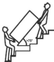
Gradient limit>75°
Location requirements
- Enough space for installation and maintenance shall be preserved.
- The air inlet and outlet should be free from obstacles and strong wind.
- The base surface should be flat, surface should be inclined no more than 2° and able to bear the weight of the unit and suitable for installing the unit without increasing noise or vibration.
- The operation noise and air flow expelled shall not affect neighbors.
• No flammable gas is leaked nearby.
• It is convenient for piping and wiring.
- If it is installed in indoor space, it might cause indoor temperature decrease and noise, please take preventive measures for this.
- If the unit has to be installed on a metal part of building, make sure the well electric insulation which should meet the relevant local electric standard.

CAUTION
- The ambient air temperature must also be considered when installing this unit, in heat pump mode the ambient air temperature must be above -7°C and below 43°C . If the ambient air temperature falls outside these upper and lower limits, the electrical elements will activate to meet the hot water demand and the heat pump will not operate.
- The unit should be located in an area not subject to freezing temperatures. The unit located in unconditioned spaces (i.e., garages, basements, etc.) may require the water piping, condensate piping, and drain piping to be insulated to shelter against freezing.

CAUTION
Installing the unit in any of the following places may lead to malfunction (If it is inevitable, consult the supplier prior to purchase).
- The unit should be located in an area not subject to freezing temperatures. The unit located in unconditioned spaces (i.e., garages, basements, etc.) may require the water piping, condensate piping, and drain piping to be insulated to shelter against freezing.
- The site contains mineral oils such as lubri cant of cutting machines.
• Seaside or where the air contains salt.
• Hot spring area where corrosive gases exist, e.g., sulfide gas.
• Factories where the power voltage fluctuates seriously.
• Inside a car or cabin.
- The place with direct sunlight and other heat supplies. If there's no way to avoid these, please install a cover.
- Places like kitchen where oil may permeate system.
- Place where strong electromagnetic fields exist.
- Place where flammable gases or materials exist.
- Place where acidic or alkaline gases exist.
• Other special environments.

WARNING
- The unit must be securely fixed, otherwise, noise and vibration may result.
• Make sure that there are no obstacle around the unit.
- In places where there are strong wind like seaside, fix the unit in a location protected from the wind.
Maintenance space requirements (unit: mm)


NOTE
The minimum clearance from the appliance to the combustible surface is not less than all installation distances in the direction corresponding to the above.

Mounting requirements
The base surface should be flat, surface should be inclined no more than 2° , otherwise the fixing strap is recommended as shown as following figures:


One side wall (top view)

Unit outline dimension (unit: mm)


INSTALLATION
The circulating air for every unit should be more than 350m3/h . Make sure there is enough Installation space. Refer outline dimensional drawing.
![graph TD A["Condensate Outlet"] --> B["PTR valve"] B --> C["anode"] C --> D["Water Outlet"] D --> E["Notice: The tempering valve is required on the hot water usage terminal."] E --> F["One Way Valve"] E --> G["Tap Water"] F --> H["Ball Valve"] G --> I["ExpansionTank for pressure relief (recommended)…](/content/2026/07/1490665/images/c205db43fad600133d3a29c5d2b048f9a57dd64d136499ba372c0cc275ad75dc.jpg)
Water System Piping
Water inlet or outlet pipes: The spec of the water inlet or outlet thread is RC3/4" (external thread). Pipes must be heat-resistant and durable.
1) Installation of the pipe for PTR valve: The valve connecting thread is RC3/4" (internal thread). After installation, it must be confirmed that the drainpipe outlet is exposed in the air.

CAUTION
- Piping water system as the above figure. In case of installing where outside temperature falls below freezing point, insulation must be provided for all hydraulic components.
- The PTR valve should be checked every half year to make sure that there is no restriction of the valve. Please beware of hot water from the valve. The drainage pipe should be well insulated in order to prevent water inside pipe from freezing in cold weather.
- PT valve is tightened with a 68N.m torque wrench. Apply sealant to the first 3 turns of screw thread before installation; After installation, the outlet of the drain pipe shall be installed face down, and the thread turns that are not screwed into the PT valve shall be less than 3 turns.
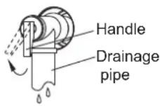

WARNING
• Do not dismantle the PTR valv.
- Do not block off the drainage pipe, it will cause explosion and injury.

EXPLOSION
2) Installation of the One Way Valve: The One Way Valve thread is RC3/4". It is used to prevent water from flowing backwards.
3) After connection of the water system piping work, turn on the cold water inlet valve and hot water outlet valve and bleed all air from the tank. When water flows smoothly out from water outlet pipe (tap water outlet), the tank is full, turn off all valves and check pipeline to make sure there is no any leakage.
4) If the inlet water pressure is less than 0.15MPa, a pump should be installed at the water inlet. To guarantee the safety usage of tank, a Pressure Limiting Valve (PLV) should be installed in the water inlet pipe, if the water pressure exceeds 0.5MPa
5) Condensate may be leaked from unit if drainage pipe is blocked, or unit operates in high humidity environment, a drainage pan is recommended as shown as following figure:


CAUTION
- The power supply should be hard wired.
- Power supply circuit should be earthed effectively. The wiring must be performed by professional technicians in accordance with national wiring regulations and the circuit diagram below.
- An all-pole disconnection device which has at least 3mm separation distance in all pole and a residual current device (RCD) with the rating of above 10mA shall be incorporated in the fixed wiring according to the national rule.
- Set the electric leakage protector according to the relevant electric technical standards of the state.
- The power cord and the signal cord shall be laid out neatly and properly without mutual interference or contact the connection pipe or valve.
- After wire connection, check it again and make sure of connection before power is turned on.
- The unit is equipped with a cord without a plug that enables connection to power via a weatherproof power outlet.
1. Specifications of Power Supply
| Model Name | RSJ-15/190RDN7-L2 |
| Power Supply | 220-240V~ 50Hz |
| Min. Diameter of Power Supply cord (mm 2 ) | 2.5 |
| Earth cord (mm 2 ) | 2.5 |
| Manual Switch(A) Capcity/Fuse (A) | 30/25 (2kW) |
| Creepage Breaker | 30 mA ≤0.1sec |
| Model Name | RSJ-23/300RDN7-L2 |
| Power Supply | 220-240V~ 50Hz |
| Min. Diameter of Power Supply cord (mm2) | 2.5 |
| Earth cord (mm2) | 2.5 |
| Manual Switch(A) Capcity/Fuse (A) | 40/30 (3kW) |
| Creepage Breaker | 30 mA ≤0.1sec |

WARNING
The unit in must be installed with an RCD near the power supply and must be effectively earthed.
2. Electric leakage protector

Installation checklist
1. Location
- The flooring beneath the water heater must be able to support the weight of the unit when filled with water (more than 445kg).
- Located outdoors and in a vertical position. Sheltered from freezing temperatures.
- Provisions made to shelter the area from water damage. Metal drain pan installed and piped to an adequate drain.
- Sufficient room to service the water heater.
- Sufficient air for the heat pump to function, the water heater must be located in a space >15m3 , and must have unrestricted air flow.
- Water Quality.
| Water heater system | Total Dissolved Solids (TDS) mg/L or ppm | Hardness (as CaCO3) mg/L or ppm | Saturation index (Langelier) | PH | Dissolved Co2 mg/L or ppm | Chlorides mg/L or ppm |
| 2500* 200 | | +0.4to-1.0@65°C | 6.5 to 9.5 | Not Applicable | Not Applicable |
| *For TDS levels up to and including 800mg/litre the magnesium based anode is to be used. It is recommended that magnesium anode be checked annually.This is the anode fitted during manufacture of the cylinder. For TDS levels greater than 800mg/litre and not exceeding 2500mg/litre the magnesium based anode is to be used. Frequently inspection of magnesium anode is recommended.This anode Can be fitted by midea or an authorized person. This Warranty does not apply if the TDS exceeds 2500 mg/litre. |

NOTE
For optimal efficiency and serviceability, the following clearances should be maintained: 800mm on the air inlet side, 800mm on the air outlet side, 600mm in the back, and 600mm in the front.
- The unit cannot be placed into any type of closet or small enclosure.
- The site location must be free from any corrosive elements in the atmosphere such as sulfur, fluorine, and chlorine. These elements are found in aerosol sprays, detergents, bleaches, cleaning solvents, air fresheners, paint, and varnish removers, refrigerants, and many other commercial and household products. In addition excessive dust and may affect the operation of the unit and require frequent cleaning.
- The ambient air temperature must be above -7°C and below 43°C . If the ambient air temperature falls outside these upper and lower limits the electrical elements will be activated to meet the hot water demand.
2. Water System Piping
- PRT (Temperature and pressure relief valve) properly installed with a discharge pipe run to an adequate drain and sheltered from freezing.
- All piping properly installed and free of leaks. Unit completely filled with water. Tempering valve installed per manufacturer's instructions.
3. Condensate Drain Line Installation
- Must be located with access to an adequate drain or condensate pump.
- Condensate drain lines installed and piped to an adequate drain or condensate pump.
4. Electrical Connections
- The water heater requires 230 VAC for proper operation.
- Wiring size and connections comply with all local applicable codes and the requirements of this manual.
• Water heater and electrical supply are properly grounded.
- Correctly sized overload fuse or circuit breaker protection installed.
5. Post Installation Review
- Understand how to use the User Interface Module to set the various modes and functions.
- Understand the importance of routine inspection/maintenance of the condensate drain pan and lines. This is to help prevent any possible drain line blockage resulting in the condensate drain pan overflowing.
- IMPORTANT: Water coming from the plastic shroud is an indicator that both condensation drain lines may be blocked. Immediate action is required.
TRIAL-RUNNING
Water affusion before operation
Before using this unit, please follow the steps below. Water Affusion: If the unit is used for the first time or used again after emptying the tank, please make sure that the tank is full of water before turning on the power. Method:
![graph LR A["Open the cool water inlet valve and the hot water outlet valve."] --> B["Open the hot water outlet"] B --> C["Water effusion"] C --> D["When water flows out from the water outlet, the tank is full. Turn off the hot water outlet valve and water affusion is finished."] D --> E["Close the h…](/content/2026/07/1490665/images/8bcc1a758bc7ed17ebf25428c29270b80b9b4e4a3fff4876c3d9489b8ba5c816.jpg)

CAUTION
- Operation without water in water tank may result in the damage of auxiliary E-heater.
- In case of such damage, the manufacturer will not be liable for any damages caused by this issue.
• After powered on, the display lights up. Users can operate the unit through the buttons under the display.
- Emptying: If the unit needs cleaning, moving etc, the tank should be emptied. Method:

![graph LR A["Cool water inlet"] --> B["Open"] B --> C["Hot water outlet"] C --> D["Open"] D --> E["Drainpipe shut-off valve"] E --> F["After emptying, please replace the nut of drainpipe."] F --> G["Close"] G --> H["Drainpipe shut-off valve"]](/content/2026/07/1490665/images/a1af3ef9ffaee873369610c45cbf44b66e5e685ea44bba5495f80f10e2ead342.jpg)
Trial- running
- Electrical Connections
1) Checking list before trial-running.
2) Correct installation of the system.
3) Correct connection of water/air piping and wiring.
4) Condensate draining smoothly well insulation work for all hydraulic part.
5) Correct power supply.
6) No air in the water pipeline and all valves opened.
7) Effective RCD installed.
8) Sufficient inlet water pressure (between 0.15MPa and 0.65MPa).
2. About Running
Unit has two kinds of heat sources: Heat pump (compressor) and electric heater. The unit will automatically select heat sources to heat water to the target temperature.

2) Water Temperature Display
The temperature shown on the display depends on the upper sensor. It is normal that the display temperature has reached to target temperature but compressor still running, because the lower water temperature does not meet to target temperature.
- Running Temperature Range
Setting water temperature target range: 55\~70°C.
E-heater running ambient temperature range: -20\~45°C.
Heat pump running ambient temperature range: -7\~43°C.
Water temperature limits:
| Model | RSJ-15/190RDN7-L2 |
| Ambient temp.(T4) | T4<-7 | -7≤T4<-2 | -2≤T4<0 | 0≤T4<38 | 38≤T4<43 | 43≤T4 |
| Max.Temp. (Heat pump) | -- | | | | 5850 60 | 45 |
| Max.Temp. (E-heater) | 70 70 | 70 70 70 | 70 | | | |
| Model | RSJ-23/300RDN7-L2 |
| Ambient temp.(T4) | T4<-7 | -7≤T4<-2 | -2≤T4<0 | 0≤T4<38 | 38≤T4<43 | T4≥43 |
| Max.Temp. (Heat pump) | -- -- | | | | 5850 6045 |
| Max.Temp. (E-heater) | 70 70 | 70 70 70 70 | | | | |
4) Heat Source Shift
- The default heating source is heat pump. If ambient temperature range is out of heat pump operating range, heat pump will stop running, the unit will shift automatically to activate E-heater and show on the display, then if the ambient temperature goes into the running range of heat pump again, it will stop E-heater and shift automatically to heat pump again, and will be extinguished.
- If the target setting water temperature is higher than Maximum temperature (Heat pump), the unit will activate heat pump firstly to the Maximum temperature, then stop heat pump, activate E-heater to continually heat water to the target temperature.
- If manually activate the E-heater running when heat pump running, E-heater and heat pump will work together until the water temperature gets to target temperature. So to increase recovery rate, please manually activate E-heater.

NOTE
E-heater will be activated once by pressing ☐ for economy mode or hybrid mode, if want to apply E-heater again, please push forced E-heating Combination button again.
If only use E-heater, about 150 liters water will be heated, so set higher target water temperature if ambient temperature is out of heat pump running range.
• Defrosting During Water-heating
In heat pump running period, if the evaporator frosted in lower ambient temperature, the system will defrost automatically to keep effective performance (about 3\~10min). At defrosting time, the fan motor will stop, but compressor will still run.
• COP
COP varies at different ambient temperature. Normally lower ambient temperature result in longer heat-up time because of lower effective performance.
- When ambient temp below 2° C, heat pump and E-heater will take different portions of heating capacity, generally the lower of ambient temperature, the lower portion of heat pump will contribute as well as the higher portion of E-heater will provide more detail please refer to Table.
- About TCO (Thermal-cutoff)
The power of E-heater will be automatically shut-off or turn on by TCO. If the water temperature is higher than 85° C, the TCO will automatically shut off the power of compressor and E-heater. After that it needs to be reset manually.
- Restart After a Long Term Stop
When the unit is restarted after a long term stop (trail running included), it is normal that outlet water is unclean. Turn the tap on and the water will be flushed clean.


NOTE
While the ambient temperature below than -7°C , heat pump will stop running, the unit will automatically shift to E-heater running.
3. Basic function
1) Weekly disinfect function
Under disinfection unit immediately start to heat water up to 60° C to kill the potential legionella bacteria inside water of tank, ✉ icon will light on the display screen during disinfection. Unit will quit disinfection if water temperature is higher than 60° C and extinguish ✉ icon.
2) Vacation function
Press the Ⓜ button to select VACATION, unit will automatically heat water to 15°C for the purpose of energy saving during vacation days.
3) How is the unit running
If unit is OFF->press 🔍 ->unit will be waken->press ∧ ∨ to set target water temperature(55-70°C)->press √ ->unit will automatically select heat source and start to heat water to target temperature.
4) Remote shutdown function:
Users can connect a switch. If the switch is closed, the unit will be stopped forcibly. If switch breaks, the unit can run normally according settings.
4. Query function
Press and hold the 🔒 button for 1 second then system running parameters will be shown one by one with following sequence by each pushing of ∧ or ∨ button.
| No. | Hour low bit | Min.high bit | Min.Low bit | unit | Explanation |
| 1 | T | S | U | Temp. | - - - |
| 2 | T | S | L | Temp. | T5L |
| 3 | T | S | I | Temp. | - - - |
| 4 | | T | S | Temp. | Heat pump stop temp |
| 5 | | T | 3 | Temp. | T3 |
| 6 | | T | 4 | Temp. | T4 |
| 7 | | T | P | Temp. | TP |
| 8 | | T | H | Temp. | Th |
| 9 | | o | n | | - - - |
| 10 | T | F | r | | - - - |
| 11 | | T | T | Temp. | Disinfect temp. |
| 12 | | C | o | Current | Compressor andelectric heating current |
| 13 | | F | o | Fan | Ac Fan Dc Fan0: OFF Real speed/101: LOW2: MID3: HIGH |
| 14 | | E | o | Machine parameters | 0~255 |
| 15 | E | E | r | | Electronic expansionvalve opening |
| 16 | E | E | C | | Compression mechanismhot water demand |
| 17 | P | U | P | | - - - |
| 18 | | P | S | | - - - |
| 19 | | F | T | | 0: Ac Fan1: Dc Fan |
| 20 | | H | T | | O(Eheater control type) |
| 21 | | H | P | | O(Compressor control type) |
| 22 | F | S | I | | --- |
| 23 | S | I | o | | Tank capacity |
| 24 | P | 4 | P | | Four-way valve status |
| 25 | | U | U | | 0 |
| 26 | | U | I | Version | Host software version |
| 27 | | U | 2 | Version | LCD panel software version |
| 28 | | U | 3 | Version | 000 |
| 29 | | U | 4 | | 0: One electric heater1: Two electric heaters |
| 30 | | U | T | | 4 |
| 31 | I | E | r | | Last error code |
| 32 | 2 | E | r | | Previous 1 st error or protection code |
| 33 | 3 | E | r | | Previous 2 nd error or protection code |
| 34 | H | H | H | | Maintenance time |
| 35 | T | L | F | | Target Temp |
| 36 | E | n | d | | End sign |
OPERATION
Control Panel Explanation

Display Explanation

| No | con Description |
| 1 | 888 will be lightened if screen is unlocked.It shows water temperature on normal;It shows remaining vacation days on vacation;It shows setting temperature on setting;It shows unit setting/running parameters,error/protection code on querying. |
| 2 | 20:08 Time and clock setting20:08 shows the clock.Whenever there is any setting for clock,SET TIME will be lightened. |
| 3 | |
| 4 | |
| 5 | |
| 6 | |
| 7 | |
| 8 | |
| 9 | |
| 10 | | High temp. AlarmIf water temp is higher than 50°C, it will be lightened, otherwise it will be extinguished. |
| 11 | 1 | Error:It will be lightened when unit is under protection/error. |
| 12 | VACATION | VACATION MODE:For the outgoing vacation mode, the water tank is set at 15°C. Maintains low tank water temperature, preheats hot water and anti-freeze lines, while reducing on/off operation of the tank. |
| 13 | HYBRID | HYBRID MODE:Operating in heat pump mode, the electric heater and heat pump will heat up together when in extremely low ambient temperatures or when the heat pump has been running for a long time without reaching the set Temp. |
| 14 | E-HEATER | E-HEATER MODE:Operate in accordance with the heat pump mode, the heat pump outdoor unit and the electric heater running at the same time. |
| 15 | ECONOMY | ECONOMY MODE:In accordance with the heat pump mode of operation, the heat pump external unit heats up to the maximum water temperature before turning on the electric auxiliary heater for heating, the heat pump and the electric auxiliary heater will not be turned on at the same time.It is recommended to use this mode of operation when making hot water alone, which is more energy-saving. |
| 16 | INVALID | When any key is invalid, this icon will flash 3 sec. |
| 17 | SET TEMP | The icon lights up when the water temperature is being set. |
| 18 | L | The icon lights up when the clock is being set. |
| 19 | | Wireless:Will be lightened when Wireless is connected;will be extinguished when Wireless is not connected;will flash with 2Hz frequency when setting Wireless. |
| 20 | HP | HEAT PUMP ICON:When the heat pump is operating and producing hot water, the icon lights up. |
| 21 | 居 | Smart Grid ICON:When the SG signal is invalid, this icon does not light up and the machine does not switch on normally.(some units) |

Any pressing of button is effective only under button and display unlocked state.
| No. | Icon Description | |
| 1 | M | Use this key to switch modeDefault HYBRID modeSwitch to E-heater modeSwitch to ECONOMY modeSwitch to VACATION modeAdjust vacation days (1-360 days)Switch to HYBRID mode |
| 2 | | Click the button to turn on the forced sterilization function Icon will light up. then the unit will heat up water to 60°C at least for disinfection.When the machine is disinfected, press this button to cancel it. then the will be extinguished.NOTE: When the operating conditions are not met to turn on this function, the corresponding icon on the wire controller lights up briefly and then goes out. |
| No | con Description | |
| 3 | | INCREASE AND DECREASEIf screen is unlocked, corresponding value will increase by pressing the button.When setting temperature, press more than 1s, temperature value will be increased continuously;When setting clock/timer, press more than 1s, clock/timer value will be increased continuously;When setting vacation days, press more than 1s, day value will be increased continuously;On querying, check items will page up by pressing it. |
| 4 | | Checking function1) In the main interface, press and hold the search key for 1 second to enter the spot check function, and use the up and down keys to switch the spot check channel, and the attribute value of the channel will be displayed when switching to the channel, and the specific channel can be found in the function book.2) After 30 seconds from the last operation of the up and down keys, or by pressing the return key or the on/off key, you can directly exit the engineering mode;3) Query mode can be entered in both power-on and power-off state. |
| 5 | | Engineering Mode1) In the main interface, press and hold the copy key for 3 seconds to enter the engineering mode; use the up and down keys to switch the inspection channel, and the attribute value of the channel will be displayed when switching to the channel. By up and down key, you can modify a parameter setting, after setting and adjusting, press confirm key to return to the main interface to make the setting effective (channel 2, 3, 4, 34, 35 will be effective immediately). Press the Return button to return to the previous interface (channel selection interface). After 30 seconds from the last operation of the up and down buttons, or by pressing the return button or the on/off button, you can directly exit the engineering mode.2) Engineering mode can be accessed in both power-on and power-off state.It is strictly prohibited for the customer to change the parameter settings of other channels in the engineering mode without authorisation to avoid affecting the normal operation of the unit or causing damage to the prototype. |
| 6 | | Power on/off buttonPress the button to turn the device on or off. |
| No | Icon Description | |
| 7 | L | TIMER (Daily setting)1) Press the TIMER button to the day timer iconday press the confirmation button to enter the day timer setting interface, the day timer has a total of 6 time periods, each time period can be set to open the time, close the time, mode, set the temperature of the water; when set the first time period set the temperature of the water, press the confirmation button to enter the next time period of the set; when set the sixth time period set the temperature of the water, press the confirmation button to return to the main interface; during this period, you can press the return buttonReturn to the previous setting or main interface;2) When setting the on time and off time, press the delete button, the time can be restored to the default value, and displaying (-. --).3) If there is a conflict between the set time periods, the time period set at the back will be the valid time period, and the time period in front will be the invalid time period; the invalid time period restores the default setting4) You can enter the daily timer setting in both power-on and power-off state.TIMER (Weekly setting)1) Press the TIMER button to the weekly timer iconWEEKpress the confirmation button to enter the weekly timer setting interface, weekly timer a total of 7 days, there are 6 time slots can be set each day, each time slot can be set to open the time, close the time, the mode, set the water temperature; when the first time slot set the water temperature, press the confirmation button to enter the next time slot settings; when the sixth time slot set the temperature, press the confirmation button to return to weekly After setting the water temperature for the 6th period, press the confirmation key to return to the selection of week; during this period, you can press the return key to return to the previous level of setting or the main interface;2) When setting the on time and off time, press the delete button to restore the time, mode and set water temperature to the default value, and displaying (-. --).3) If you adjust the timing time again after the setting is completed, then all the settings after the adjustment time period will be canceled. For example, if you adjust the timer on for time period 2, the timer off for time period 2, and the settings for time periods 3, 4, 5, and 6 will all be canceled to (-:---) after adjustment. Mode and setting water temperature become default values (Energy saving mode, 60°C)4) In the weekly timer setting, in the weekly selection, use the copy button, you can locate the setting of a certain day to the base day, select other days, press the copy button to change the status of the day, the fast flashing is selected, the slow flashing is unselected, and after pressing on the confirmation button, you can copy the setting of the base day to the selected day;5) You can enter the weekly timer setting in both power-on and power-off state. |
| 8 | √ | CONFIRM/UNLOCKIf screen and buttons are unlocked, press it to upload setting parameters after setting any parameter. |
Using the SmartHome App
⚠ Ensure that your mobile phone is connected to the home wireless network, the 2.4GHz band wireless signal is enabled on your wireless router and you know the network password.
⚠️ Turn on Bluetooth on your phone and the device must also be powered up.
■ Step 1: Download the SmartHome app
Scan the QR code below to download the SmartHome app from app store or search for it directly on the Google Play Store or Apple's App Store.

■ Step 2: Log in
Open the SmartHome app. Log in directly if you have an existing SmartHome account or create a new account.
Alternatively, you can also use a 3rd party login platform.

■ Step 3: Connecting the device
1) When you log in, you may see the message "Smart devices discovered nearby". Tap to add your device.

2) If no such message appears, proceed as follows:
Tap on "+" and select your device in the list of nearby available devices. If your device is not listed, please add your device manually, first selecting the device category e.g. Water Heater.

3) Follow the steps in the app to connect your device to the wireless network. If your device fails to connect, follow the additional instructions in the app.

■Step 4: Controlling the device
After pairing successfully, a card will be created for the device in the SmartHome app.Shortcuts for basic functions will appear on the card such as changing the humidity or switching the device on or off.Tapping on the card, will reveal additional features and settings. The actual UI design may look different from examples due to app updates.

Compliance
We, hereby declare that this device is in compliance with the relevant provisions of RE Directive 2014/53/EU. A copy of the full DoC is attached (Europen Union products only). Wireless module mod els:
EU-SK110, US-SK110:
FCC ID: 2ADQOMDNA23
IC: 12575A-MDNA23
BLE:2402-2480MHz, TX Power:<10dBm
Wi-Fi:2400-2483.5MHz, TX Power:<20dBm
This device complies with Part 15 of the FCC Rules and it contains licence exempt transmitter (s)/ receiver (s)that comply with Innovation, Science and Economic Development Canada's licence-exempt RSS (s).Operation is subject to the following two conditions:
1) This device may not cause harmful interference;
2) This device must accept any interference, including interference that may cause undesired operation of the device.
Only operate the device in accordance with the instructions supplied. Changes or modifications to this unit not expressly
approved by the party responsible for compliance could void the user's authority to operate the equipment. This device
complies with FCC radiation exposure limits set forth for an uncontrolled environment. In order to avoid the possibility of exceeding the FCCradio frequency exposure limits, human proximity to the antenna shall not be less than 20cm (8 inches) during normal operation.
In Canada:
CAN ICES-3(B)/NMB-3(B)
This equipment has been tested and found to comply with the limits for a Class B digital device, pursuant to part 15 of the FCC Rules. These limits are designed to provide reasonable protection against harmful interference in a residential installation.
This equipment generates, uses and can radiate radio frequency energy and, if not installed and used in accordance with the instructions, may cause harmful interference to radio communications. However, there is no guarantee that interference will not occur in a particular installation.
If this equipment does cause harmful interference to radio or television reception, which can be determined by turning the equipment off and on, the user is encouraged to try to correct the interference by one or more of the following measures:
- Reorient or relocate the receiving antenna.
- Connect the equipment into an outlet on a circuit different from that to which the receiver is connected.
- Consult the dealer or an experienced radio/TV technician for help.
Auto-restart
If electricity power failed, unit can memorize all setting parameters, unit will be back to the previous setting when power recover.
When there is no operation of button for 1 minute, button will be locked except Unlock button ☐ + 📋 for 2s, unlock buttons.
Screen Auto Lock
If there is no operation of button for 60s, screen will be locked(extinguished) except for error code and alarm icon. Press any button will unlock the screen(lighten). Enter engineering mode 35 channel enable this function.
MAINTENANCE
Maintenance Recommended regular maintenance
table
1) Check the connection between power supply plug and socket and ground wiring regularly;
2) In some cold area (below 0° C), if the system will be stopped for a long time, all the water should be released in case of freezing of inner tank and damage of E-heater.
3) It is recommended to clean the inner tank and E-heater every half year to keep an efficient performance.
4) Check the anode every half year and change if required. For more details, please contact the supplier or the after-sale service.
5) It is recommended to set a lower temperature to decrease the heat release, prevent scale and save energy if the outlet water volume is sufficient.
6) Before shutting the system off for a long time, please: Shut off the power supply; Release all the water in water tank and the pipeline and close all the valves; Check the inner components regularly.
7) How to change the anode;
- Turn off the power, and turn off the water inlet valve.
- Open hot water tap, and decrease the pressure of the inner container.
| Checking Item | Checking content | Checking frequency | Action |
| 1 | air filter (inlet/outlet) | every month Clean the filter | |
| 2 | anode every half year | | Replace it if it has been used out |
| 3 | inner tank every half year Clean the tank | | |
| 4 | E-heater every half year Clean E-heater |
| 5 | PTR valve | every year | Operate the hander of PTR valve to ensure that waterways are clear. |
| If water doesn't flow freely when operating the hander, replace PTR valve with a new one |

TROUBLE SHOOTING
Non-error tips
Q: Why compressor can't start immediately after setting?
A: Unit will wait for 3 min to balance the pressure of system before start compressor again, it's a self protection logic of unit.
Q: Why sometimes the temperature shown on the display panel decreased while unit is running?
A: When the upper tank temperature is much higher than the bottom part, upper part hot water will be mixed by the bottom cold water which is continually flow from inlet tap water so that will decrease the upper part temperature.
Q: Why sometimes the temperature shown on the display decreased but unit still keep closed?
A: to avoid unit ON/OFF frequently, unit will activate heat source only when bottom tank temperature is lower than setting temperature.
Q: Why sometimes the temperature shown on the display will decreased dramatically?
A: Because tank is pressure-bearable type, if there is massive hot demand, hot water will quickly tapped out from upper part of tank as well as cold water will quickly tapped into bottom part of tank, if the cold water surface emerge the upper temperature sensor, temperature shown on the display will decreased dramatically.
Q: Why sometimes the temperature shown on the display is decreased a lot, but there is still a mount of hot water can be tapped?
A: Because the upper water sensor is located on the upper 1/4 tank, when tapping hot water out, it means there is at least 1/4 tank of hot water available.
Q: Why sometimes unit shows "EHLA" on display?
A: When the unit does not have electric heating function, the heat pump available running ambient air inlet range is -7-43°C, if ambient air inlet temperature is out of range, system will show above-mentioned signal to let user notice it.
Q: Why sometimes the buttons are unavailable?
A: if there is no operation on panel for 60s, unit will lock the panel, shows "☐", to unlock the panel, please press the "☐" + "☑" button for 2 seconds.
Q: Why sometimes there is some water flowed from drainage pipe of safety valve?
A: Because the tank is pressure-bearable one, when water is heated inside the tank, water will expand, so the pressure inside of tank will increase, if pressure goes up more than 1.0Mpa, safety valve will activate to relief the pressure and hot water drop will be discharged correspondingly. If water drop is continually discharged from safety valve drainage pipe, it is abnormal, please contact qualified stuff to repair.
Something about self-protection of unit
When the self-protection happens, the system will be stopped and start self-check, and restart when the protection resolved. When the self-protection happens, the ____ will flash and error code will be shown at water temperature indicator. But the ____ and error code ① does not disappear until protection resolved. In the following circumstance, self-protection may happen: Air inlet or outlet is blocked; The evaporator is covered with too much dust; Incorrect power supply (exceeding the range of 220-240V).
①
When Error happened
1) If some normal errors happen, unit will automatically shift to E-heater for emergent SHW supply, please contact qualified sta to repair.
2) If some sever error happen, unit will not start, please contact qualified sta to repair.
Error phenomenon shooting
| Error phenomenon | Possible reason solution | |
| Cold water tapped out and display screen extinguished | 1. Bad connection between power supply plug and socket;2. Setting water temperature too low;3. Temp. sensor broken; PCB of indicator broken. | 1. Plug in;2. Setting water temp. higher;3. Contact service center. |
| No hot water tapped out | 1. Public water supply ceased;2. Cold water inlet pressure too low (<0.15 MPa);3. Cold water inlet valve closed. | 1. Waiting for public water supply recover;2. Waiting for inlet water pressure increase;3. Open water inlet valve. |
| Water leakage | Hydraulic pipeline joints are not sealed well. | Check and reseal all joints. |
| Malfunction Description Corrective actionDisplay | |
| EH0b | Tank and LCD panel communication error. | Maybe the connection between LCD panel and PCB has released or PCB has been broken. |
| EH00 | Machine working parameters are abnormal. | Contact a qualified person to service the unit. |
| Dc fan fault. | Maybe the connection between fan and PCB has released or fan has been broken. Contact a qualifiederson to service the unit. |
| PH15 | Electric leakage error. If PCB current_induction_circuit check the current difference between L,N >14mA, system consider it as"electric leakage error". | Maybe some wires have been broken or bad wire connection. Contact a qualified person to service the unit. |
| Compressor discharge temperature sensor TP error. | Maybe the connection between sensor and PCB has released or sensor has been broken. Contact a qualifiedperson to service the unit. |
| Compressor suction temperature sensor TH error. | Maybe the connection between sensor and PCB has released or sensor has been broken. Contact a qualifiedperson to service the unit. |
| EC53 | Ambient temperature sensor T4 error. | Maybe the connection between sensor and PCB has released or sensor has been broken. Contact a qualifiedperson to service the unit. |
| EC52 | Evaporator temperature sensor T3 error. | Maybe the connection between sensor and PCB has released or sensor has been broken. Contact a qualifiedperson to service the unit. |
| EH5L | Error of sensor T5L(lower water temperature sensor) | Maybe the connection between sensor and PCB has released or sensor has been broken. Contact a qualifiedperson to service the unit. |
| EHLA | When the ambient temperature T4 is out of the compressor operating range, the compressor stops, and EHLA is displayed until T4 returns to the normal range. Only works on units without electric heaters.Devices with electric heaters will never display "EHLA". | It is normal, and no necessary to repair. |
| EH5d electric heater open-circuit error | Maybe the electric heater has been broken or bad wire connection after repair. |
| EHHP | Heat pump system fault.When PH20, PH21, PC30, PC06 any protection appears 3 times or the protection lasts 1 hour. | The compressor works abnormally. Contact a qualifiedperson to service the unit. |
| PHdH Dry burning protection. | Ensure that there is water in the water tank before heating. |
| PH20 | Compressor abnormally stopped protection The discharge temperature is not so higher than evaporator temperature after compressor running a term. | Maybe because of compressor broken or bad connection between PCB and compressor. Contact a qualified person to service the unit. |
| PH21 The working current of the compressor is too large. | Maybe because of compressor broken, system blocked, air or water or more refrigerant in system(after repair),water temperature sensor malfunction, ect. Contact aqualified person to service the unit. |
| PH24 | Frost protection.T5L< 4°C and T4 < 7°C | The cold water temperature is too low, which will affect the water tank. The electric heater will work. |
| PC30 | System high pressure protection ≥3.0MPa active; ≤2.4Mpa inactive | Maybe because of system blocked, air or water or more refrigerant in system(after repair), water temperature sensor malfunction, ect. Contact a qualified person to service the unit. |
| PC06 | High TP protection.Tp>110°C, Protection active Tp<90°C, Protection inactive | Maybe because of system blocked, air or water or less refrigerant(leakage) in system( after repair), water temperature sensor malfunction, ect. Contact a qualifiedperson to service the unit. |
| PH9b | Overtemperature protection.The current water temperature exceeds the target temperature by more than 5 °C. | The water temperature sensor is faulty or the current water temperature is too high. In case of burns, contact a qualifiedperson to check. |
| PH91 | Low T3 protection. | If the fault persists, Contact a qualified person to service the unit. |
HEAT PUMP MANUFACTUR-ER'S WARRANTY
This warranty is provided by Midea. It applies to heat pumps installed in a single family dwelling only and is provided only to those acquiring the heat pump as consumers within the meaning of the Australian Consumer Law. The terms of the warranty are effective from the date the heat pump is installed. Midea may verify this date by requesting a copy of the compliance certificate that accompanied the installation. The compliance certificate is mandatory in all Australian states and territories.
Warranty period
Midea warrants that the following heat pump components will remain free of defects for the specified periods from the date of installation:
• Storage Tank- 5 years.
- Compressor- 3 years.
- All other components supplied by Midea, including valves, elements, thermostats and sacrificial anodes - 1 year.
- Midea gives no warranty in relation to components not supplied by Midea, for example tempering valves and cold water valve assemblies used by installers.
Subject to the conditions and exclusions specified in this warranty, Midea will at its own expense repair or replace any defective heat pump component covered by this warranty as soon as reasonably practicable after the consumer has reported the defect to Midea.
Consumers must register the warranty
To be eligible to make a claim under this warranty, consumers must complete all details in the Installation Report & Warranty Registration form provided with the heat pump within 6 weeks of installation and send it to the address shown on the form.
Procedure to make a claim under warranty
Upon discovering a suspected defect, consumers should immediately report the suspected defect:
- To the installer or supplier, if the suspected defect arises as a result of the installation of the heat pump or relates to any components not covered by this warranty.
- To Midea on the phone number below during the relevant warranty period, if the suspected defect relates to any components covered by this warranty.
Specific exclusions
To the extent permitted by law Midea does not accept liability under this warranty:
1) If any component of the heat pump has been installed, repaired, repositioned or modified by a person other than an appropriately qualified person approved by Midea in accordance with Midea's installation and maintenance instructions and relevant local and statutory requirements;
2) For loss or damage caused by a fault or defect in the installation of the heat pump;
3) If corrosion has occurred because the anode has not been changed in accordance with the owner's manual;
4) If a cold water expansion valve, check valve and strainer is not fitted in areas where mains pressure is likely to exceed 0.65MPa;
5) For any damage arising as a result of an accident, act of God or other circumstances beyond Midea's control;
6) If the inner cylinder has collapsed as a result of an incorrect filling and/or commissioning procedure;
7) For components not supplied by Midea that are used in the installation of Midea heat pump water heaters e.g. tempering valves, cold water valve assemblies, etc.
8) For extended or implied warranties not formally provided by Midea;
9) For external labour or equipment costs (e.g. cranes and lifting devices) required for repairs;
10) For costs incurred for rectifying faults (or perceived faults) not directly attributed to the Midea heat pump water heater;
11) For travel costs of service agents that exceed 30 kilometres;
12) For all consequential loss or damage arising from defects that can lawfully be excluded;
13) For any other issues not directly attributable to defects in components supplied by Midea including:
(a) Damage caused by incorrect commissioning;
(b) Leakage from valves not supplied by Midea;
(c) Leakage from the pressure temperature relief valve where the water pressure or temperature exceeds the limits specified in Midea's installation and maintenance instructions;
(d) Water hammer;
(e) External rust on the storage tank;
(f) Insufficient hot water because:
(i) The consumer refuses to use the auxiliary booster;
(ii) Of an incorrectly set or faulty tempering or mixing valve;
(iii) Of faulty or incomplete installation;
(iv) The water heater is too small for its required purpose;
(v) Of insufficient water flow as a result of “water saving” tap-ware or appliances;
(vi) Of blown fuses, “tripped” electrical switches or inadequate household electrical wiring;
(vii) Insufficient water flow caused by debris accumulating in water strainer.
TRADEMARKS, COPYRIGHTS AND LEGAL STATEMENT
Midea logo, word marks, trade name, trade dress and all versions thereof are valuable assets of Midea Group and/or its affiliates (“Midea”), to which Midea owns trademarks, copyrights and other intellectual property rights, and all goodwill derived from using any part of an Midea trademark. Use of Midea trademark for commercial purposes without the prior written consent of Midea may constitute trademark infringement or unfair competition in violation of relevant laws.
This manual is created by Midea and Midea reserves all copyrights thereof. No entity or individual may use, duplicate, modify, distribute in whole or in part this manual, or bundle or sell with other products without the prior written consent of Midea.
All the described functions and instructions were up to date at the time of printing this manual. However, the actual product may vary due to improved functions and designs.
DISPOSAL AND RECYCLING
Important instructions for environment(European Disposal Guidelines)
Compliance with the WEEE Directive and Disposing of the Waster Product: This product complies with EU WEEE Directive (2012/19/EU). This product bears a classification symbol for waster electrical and electronic equipment (WEEE).
This symbol indicates that this product shall not be disposed with other household wastes at the end of its service life. Used device must be returned to official collection point for recycling of electrical electronic devices. To find these collection systems please contact to your local authorities or retailer where the product was purchased. Each household performs important role in recovering and recycling of old appliance. Appropriate disposal of used appliance helps prevent potential negative consequences for the environment and human health.

DATA PROTECTION NOTICE
For the provision of the services agreed with the customer,
we agree to comply without restriction with all stipulations of applicable data protection law, in line with agreed countries within which services to the customer will be delivered, as well as, where applicable, the EU General Data Protection Regulation (GDPR).
Generally, our data processing is to fulfil our obligation under contract with you and for product safety reasons, to safeguard your rights in connection with warranty and product registration questions. In some cases, but only if appropriate data protection is ensured, personal data might be transferred to recipients located outside of the European Economic Area.
Further information are provided on request. You can contact our Data Protection Officer via MideaDPO@midea.com. To exercise your rights such as right to object your personal date being processed for direct marketing purposes, please contact us via MideaDPO@midea.com. To find further information, please follow the QR
Importer: JH Electrical and Appliance Ltd
372 Broadway, Newmarket, Auckland, New Zealand 1023
Manufacturer: GD Midea Air-Conditioning Equipment Co., Ltd.
Lingang Road Beijiao Shunde Foshan Guangdong
People's Republic of China 528311
The design and specifications are subject to change without prior notice for product improvement. Consult with the sales agency or manufacturer for details. Any updates to the manual will be uploaded to the service website, please check for the latest version.

make yourself at home

www.midea.com
© Midea 2022 all rights reserved
MD23IU-001AW
16125300A17408
20240621