
BE-GTL2TS.C1S - Electrical switch MDT - Free user manual and instructions
Find the device manual for free BE-GTL2TS.C1S MDT in PDF.


| Product Type | KNX Smart Thermostat / Controller |
| Brand | MDT |
| Model | BE-GTL2TS.C1S |
| Dimensions (W x H x D) | 90 x 90 x 30 mm |
| Weight | 0.2 kg |
| Power Supply | 24 V DC via KNX bus |
| Bus Communication | KNX (twisted pair, TP1-256) |
| Display | Backlit LCD, 2.8 inch |
| User Interface | Touch screen and capacitive buttons |
| Main Functions | Temperature control, scheduling, presence simulation, energy monitoring |
| Mounting | Flush-mounted (wall box) |
| Protection Class | IP20 |
| Operating Temperature | 0°C to +45°C |
| Storage Temperature | -20°C to +70°C |
| Relative Humidity | 5% to 95% (non-condensing) |
| Compliance | CE, KNX certified |
| Maintenance & Cleaning | Clean with a soft, dry cloth. Do not use liquids or abrasive cleaners. |
| Safety Instructions | Installation by qualified electrician only. Disconnect power before servicing. |
| Spare Parts & Repairability | No user-serviceable parts. Contact MDT support for repairs. |
| General Information | Part of MDT KNX system for home and building automation. |
Frequently Asked Questions - BE-GTL2TS.C1S MDT
User questions about BE-GTL2TS.C1S MDT
0 question about this device. Answer the ones you know or ask your own.
Ask a new question about this device
Download the instructions for your Electrical switch in PDF format for free! Find your manual BE-GTL2TS.C1S - MDT and take your electronic device back in hand. On this page are published all the documents necessary for the use of your device. BE-GTL2TS.C1S by MDT.
USER MANUAL BE-GTL2TS.C1S MDT
KNX Glass Push Button II Lite
BE-GTLxxx.x1
Further Documents:
Datasheet:
https://www.mdt.de/EN_Downloads_Datasheets.html
Assembly and Operation Instructions:
https://www.mdt.de/EN_Downloads_Instructions.html
Solution Proposals for MDT products:
https://www.mdt.de/en/for-professionals/tips-tricks.html


1 Content
2 Overview....4
2.1 Overview devices....4
2.2 Functions....5
2.3 Wiring diagram 6
2.4 Structure & Handling....7
2.5 Commissioning....7
3 Communication Objects....8
3.1 Standard settings of the communication objects....8
4 ETS Parameter....18
4.1 General Settings....18
4.1.1 Device selection....18
4.1.2 General settings....18
4.2 Button functions – General....20
4.3 Button functions....22
4.3.1 Identical parameter....22
4.3.1.1 Lock object 22
4.3.1.2 Button/Object description....22
4.3.2 Switch (General) 23
4.3.2.1 Switching with two-button function 24
4.3.2.2 Subfunction: Switch 25
4.3.2.3 Subfunction: Toggle....25
4.3.2.4 Subfunction: Send status....26
4.3.3 Send values....27
4.3.3.1 Subfunction: Send values....27
4.3.3.2 Subfunction: Toggle values/scenes 30
4.3.3.3 Subfunction: Shift value....33
4.3.3.4 Subfunction: Send values by state....35
4.3.3.5 Subfunction: Multitouch-function 36
4.3.4 Switch/send values short/long (with 2 objects) 38
4.3.5 Scene....41
4.3.6 Blinds/Shutter 42
4.3.7 Dimming....45
4.3.8 Slap/Cleaning function 46
4.4 Status LED 48
4.4.1 LED basic setting....48
4.4.2 LED 1 - 4....50
4.4.2.1 Priority 53
4.5 Logic....54
4.5.1 Logic basic settings....54
4.5.2 Setting Logic 1 - 4....54
4.5.3 Submenu - Logic 1 - 4....56
4.6 Temperature 58
5 Index 60
5.1 List of illustrations....60
5.2 List of tables....61
6 Appendix....63
6.1 Legal provisions....63
6.2 Disposal 63
6.3 Assembly 63
6.4 History 63
2 Overview
2.1 Overview devices
This manual refers to the following devices (order number in bold):
BE-GTL10W.01 Glass Push Button II Lite 1 gang, RGBW, neutral, White
BE-GTL1TW.01 Glass Push Button II Lite 1 gang, RGBW, neutral, temperature sensor, White
BE-GTL10W.A1 Glass Push Button II Lite 1 gang, RGBW, blinds, White
BE-GTL1TW.B1 Glass Push Button II Lite 1 gang, RGBW, switch, temperature sensor, White
BE-GTL10S.01S Glass Push Button II Lite 1 gang, RGBW, neutral, Black
BE-GTL1TS.01S Glass Push Button II Lite 1 gang, RGBW, neutral, temperature sensor, Black
BE-GTL10S.A1S Glass Push Button II Lite 1 gang, RGBW, blinds, Black
BE-GTL1TS.B1S Glass Push Button II Lite 1 gang, RGBW, switch, temperature sensor, Black
BE-GTL20W.01 Glass Push Button II Lite 2 gang, RGBW, neutral, White
BE-GTL2TW.01 Glass Push Button II Lite 2 gang, RGBW, neutral, temperature sensor, White
BE-GTL20W.A1 Glass Push Button II Lite 2 gang, RGBW, blinds, White
BE-GTL2TW.B1 Glass Push Button II Lite 2 gang, RGBW, switch, temperature sensor, White
■ BE-GTL2TW.C1 Glass Push Button II Lite 2 gang, RGBW, blinds/switch, temperature sensor, White
■ BE-GTL2TW.D1 Glass Push Button II Lite 2 gang, RGBW, switch/blinds, temperature sensor, White
BE-GTL20S.01S Glass Push Button II Lite 2 gang, RGBW, neutral, Black
BE-GTL2TS.01S Glass Push Button II Lite 2 gang, RGBW, neutral, temperature sensor, Black
BE-GTL20S.A1S Glass Push Button II Lite 2 gang, RGBW, blinds, Black
BE-GTL2TS.B1S Glass Push Button II Lite 2 gang, RGBW, switch, temperature sensor, Black
■ BE-GTL2TS.C1S Glass Push Button II Lite 2 gang, RGBW, blinds/switch, temperature sensor, Black
■ BE-GTL2TS.D1S Glass Push Button II Lite 2 gang, RGBW, switch/blinds, temperature sensor, Black
■ BE-GTL40W.01 Glass Push Button II Lite 4 gang, RGBW, neutral, White
BE-GTL4TW.01 Glass Push Button II Lite 4 gang, RGBW, neutral, temperature sensor, White
BE-GTL40S.01S Glass Push Button II Lite 4 gang, RGBW, neutral, Black
BE-GTL4TS.01S Glass Push Button II Lite 4 gang, RGBW, neutral, temperature sensor, Black
2.2 Functions
Extensive button functions
A function can be triggered by a single button or a pair of buttons. This provides a wide range of operating options. The button functions include "switch", "send values", "scene", "switch/send values short/long (with 2 objects)", "blinds/shutter" and "dimming".
Innovative group control
With the innovative group control, standard functions can be enhanced by pressing the button extra long. For example, the blind function in a living room. A single blind is operated with the normal short/long key press. With the additional extra long key press, for example, all blinds in the living room (group) are operated centrally. The innovative group control can also be used for lighting. A short button press switches a single light on or off, a long button press switches on or off, for example, every light in the room, and an extra long button press switches on or off, for example, every light on the entire floor.
Multitouch-function
With the multitouch-function, up to 4 different functions can be programmed on a single button. A separate datapoint type is available for each function, which means that different functions can also be triggered.
RGBW State LEDs
One RGBW status LED is available for each button. The status LED reacts to key presses or external/internal objects. The colours red, green, yellow, blue, pink, cyan and white can be assigned. A separate LED is available for the colour white to provide a clear, high-quality white. Various colours and brightness levels can be assigned using a day/night object. A priority object offers the option of visualising important states via LED.
Integrated temperature sensor (Only BE-GTLxTx.x1)
The integrated temperature sensor can be used for room temperature control. The measured temperature value of the sensor is sent to the integrated temperature controller of the MDT heating actuator. This eliminates the need for an additional temperature sensor in the room. The sending conditions of the temperature value are adjustable. An upper and lower threshold value are available for limit monitoring.
Slap function
The slap function, which is triggered by touching the entire surface of the button, allows intuitive operation. This function can be used, for example, to switch on the light when entering the room without the user having to search for the exact position of the single buttons.
Logic functions
A variety of function calls can be realised through a total of 4 logic blocks. The logic function can process both internal and external objects.. The logic function can process both internal and external status information.
Updateable via DCA
If necessary, the device can be updated using the MDT update tool (DCA).
The download is available free of charge at www.mdt.de and www.knx.org.
Long Frame Support
The device supports “long frames” (longer telegrams). These contain more user data per telegram, which significantly reduces the programming time.
2.3 Wiring diagram
The following picture shows the exemplary wiring diagram:
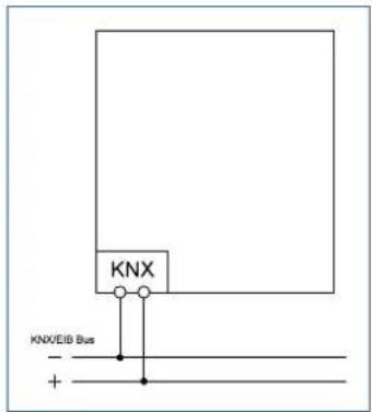
Figure 1: Exemplary wiring diagram
2.4 Structure & Handling
The following pictures show the structure of the push-buttons:

Structure: BE-GTL4xx.x1

Structure: BE-GTL2xx.x1
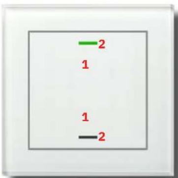
Structure : BE-GTL1xx.x1

Back side: BE-GTLxxx.x1
1 - Sensor surfaces
2 - RGBW Status LEDs
3 - Programming button
4 - KNX Busconnection terminal
Figure 2: Structure and Handling
2.5 Commissioning
- Wire the device according to the wiring diagram.
- Connect the interface to the bus.
- Switch on bus voltage.
- Press the programming button on the device.
(the status LEDs flash red alternately at the top and bottom). - Set and programme the individual address in the ETS (Status LEDs turn off).
- Configure and programme the settings in the application programme.
3 Communication Objects
3.1 Standard settings of the communication objects
| Standard Settings – Buttons | |||||||
| No. | Name Object Function Length | C R W T U | |||||
| 0 PB1:PB1/2: | Switch 1 Bit | ■ | ■ | ||||
| 0 PB1: Toggle 1 Bit | ■ | ■ | |||||
| 0 PB1: Send status 1 Bit | ■ | ■ | |||||
| 0 PB1:PB1/2: | Forcible control 2 Bit | ■ | ■ | ||||
| 0 PB1:PB1/2: | Percent value | 1 Byte | ■ | ■ | |||
| 0 PB1:PB1/2: | Decimal value | 1 Byte | ■ | ■ | |||
| 0 PB1:PB1/2: | Scene | 1 Byte | ■ | ■ | |||
| 0 PB1:PB1/2: | Colour temperature | 2 Byte | ■ | ■ | |||
| 0 PB1:PB1/2: | Temperature value | 2 Byte | ■ | ■ | |||
| 0 PB1:PB1/2: | Brightness value | 2 Byte | ■ | ■ | |||
| 0 PB1:PB1/2: | RGB value | 3 Byte | ■ | ■ | |||
| 0 PB1:PB1/2: | HSV value | 3 Byte | ■ | ■ | |||
| 0 PB1:PB1/2: | Blinds/Shutter Up/Down | 1 Bit | ■ | ■ | |||
| 0 PB1:PB1/2: | Dimming On/Off | 1 Bit | ■ | ■ | |||
| 0 PB1/2 short | Shutter Up/Down/Stop | 1 Bit | ■ | ■ | |||
| 0 PB1 short:PB1/2 short: | Switch 1 Bit | ■ | ■ | ||||
| No. | Name Object Function Length C R W T U | ||||||
| 0 PB1 short:PB1/2 short: | Toggle 1 Bit | ■ | ■ | ||||
| 0 PB1 short:PB1/2 short: | Forcible control 2 Bit | ■ | ■ | ||||
| 0 PB1 short:PB1/2 short: | Percent value 1 Byte | ■ | ■ | ||||
| 0 PB1 short:PB1/2 short: | Decimal value 1 Byte | ■ | ■ | ||||
| 0 PB1 short:PB1/2 short: | Scene 1 Byte | ■ | ■ | ||||
| 0 PB1 short:PB1/2 short: | Colour temperature | 2 Byte | ■ | ■ | |||
| 0 PB1 short:PB1/2 short: | Temperature value | 2 Byte | ■ | ■ | |||
| 0 PB1 short:PB1/2 short: | Brightness value | 2 Byte | ■ | ■ | |||
| 0 PB1 short:PB1/2 short: | RGB value | 3 Byte | ■ | ■ | |||
| 0 PB1 short:PB1/2 short: | HSV value | 3 Byte | ■ | ■ | |||
| 0 PB1, 1x tip: | Switch | 1 Bit | ■ | ■ | |||
| 0 PB1, 1x tip: | Forcible control 2 Bit | ■ | ■ | ||||
| 0 PB1, 1x tip: | Percent value 1 Byte | ■ | ■ | ||||
| 0 PB1, 1x tip: | Decimal value 1 Byte | ■ | ■ | ||||
| 0 PB1, 1x tip: | Scene 1 Byte | ■ | ■ | ||||
| 0 PB1, 1x tip: | Colour temperature | 2 Byte | ■ | ■ | |||
| 0 PB1, 1x tip: | Temperature value | 2 Byte | ■ | ■ | |||
| 0 PB1, 1x tip: | Brightness value | 2 Byte | ■ | ■ | |||
| 0 PB1, 1x tip: | RGB value | 3 Byte | ■ | ■ | |||
| 0 PB1, 1x tip: | HSV value | 3 Byte | ■ | ■ | |||
| 0 PB1, tip: | Switch | 1 Bit | ■ | ■ | |||
| 0 PB1, tip: | Forcible control 2 Bit | ■ | ■ | ||||
| 0 PB1, tip: | Percent value 1 Byte | ■ | ■ | ||||
Standard Settings – Buttons
| No. | Name Object Function Length | C | R | W | T | U | |||||
| 0 PB1, tip: Decimal value 1 Byte | ■ | ■ | |||||||||
| 0 PB1, tip: Scene 1 Byte | ■ | ■ | |||||||||
| 0 PB1, tip: Colour temperature 2 Byte | ■ | ■ | |||||||||
| 0 PB1, tip: Temperature value 2 Byte | ■ | ■ | |||||||||
| 0 PB1, tip: Brightness value | 2 Byte | ■ | ■ | ||||||||
| 0 PB1, tip: RGB value | 3 Byte | ■ | ■ | ||||||||
| 0 PB1, tip: HSV value | 3 Byte | ■ | ■ | ||||||||
| 1 PB1: Status for toggle 1 Bit | ■ | ■ | ■ | ■ | |||||||
| 1 PB1: Dimming relative PB1/2: | 4 Bit | ■ | ■ | ||||||||
| 1 PB1, 2x tip: Switch 1 Bit | ■ | ■ | |||||||||
| 1 PB1, 2x tip: Forcible control 2 Bit | ■ | ■ | |||||||||
| 1 PB1, 2x tip: Percent value 1 Byte | ■ | ■ | |||||||||
| 1 PB1, 2x tip: Decimal value 1 Byte | ■ | ■ | |||||||||
| 1 PB1, 2x tip: Scene 1 Byte | ■ | ■ | |||||||||
| 1 PB1, 2x tip: Colour temperature 1 Byte | ■ | ■ | |||||||||
| 1 PB1, 2x tip: Temperature value 2 Byte | ■ | ■ | |||||||||
| 1 PB1, 2x tip: Brightness value 2 Byte | ■ | ■ | |||||||||
| 1 PB1, 2x tip: RGB value 3 Byte | ■ | ■ | |||||||||
| 1 PB1, 2x tip: HSV value 3 Byte | ■ | ■ | |||||||||
| 1 PB1 short: Status for toggle PB1/2 short: | 1 Bit | ■ | ■ | ■ | ■ | ||||||
| 1 PB1 PB1/2: Stop/Slats Open/Close 1 Bit | ■ | ■ | |||||||||
| 1 PB1/2 long: Central: Shutter Up/Down/Stop 1 Bit | ■ | ■ | |||||||||
| 1 PB1: Status: Percent value PB1/2: | 1 Byte | ■ | ■ | ■ | ■ | ||||||
| 1 PB1: Status: Decimal value PB1/2: | 1 Byte | ■ | ■ | ■ | ■ | ||||||
| 1 PB1: Status: Colour temperature PB1/2: | 2 Byte | ■ | ■ | ■ | ■ | ||||||
| Standard Settings – Buttons | |||||||
| No. | Name Object Function Length | C R W T U | |||||
| 1 PB1:PB1/2: | Status: Brightness value 2 Byte | ■ ■ ■ ■ | |||||
| 1 PB1:PB1/2: | Status: Temperature value 2 Byte | ■ ■ ■ ■ | |||||
| 2 PB1 Group long:PB1/2 Group long: | Switch 1 Bit | ■ | ■ | ||||
| 2 PB1: Group long: Toggle | 1 Bit | ■ | ■ | ||||
| 2 PB1 Group long:PB1/2 Group long: | Forcible control | 2 Bit | ■ | ■ | |||
| 2 PB1 Group long:PB1/2 Group long: | Percent value | 1 Byte | ■ | ■ | |||
| 2 PB1 Group long:PB1/2 Group long: | Decimal value | 1 Byte | ■ | ■ | |||
| 2 PB1 Group long:PB1/2 Group long: | Scene | 1 Byte | ■ | ■ | |||
| 2 PB1 Group long:PB1/2 Group long: | Colour temperature | 2 Byte | ■ | ■ | |||
| 2 PB1 Group long:PB1/2 Group long: | Temperature value | 2 Byte | ■ | ■ | |||
| 2 PB1 Group long:PB1/2 Group long: | Brightness value | 2 Byte | ■ | ■ | |||
| 2 PB1 Group long:PB1/2 Group long: | RGB value | 3 Byte | ■ | ■ | |||
| 2 PB1 Group long:PB1/2 Group long: | HSV value | 3 Byte | ■ | ■ | |||
| 2 PB1, 3x tip: | Switch 1 Bit | ■ | ■ | ||||
| 2 PB1, 3x tip: | Forcible control | 2 Bit | ■ | ■ | |||
| 2 PB1, 3x tip: | Percent value | 1 Byte | ■ | ■ | |||
| 2 PB1, 3x tip: | Decimal value | 1 Byte | ■ | ■ | |||
| 2 PB1, 3x tip: | Scene | 1 Byte | ■ | ■ | |||
| 2 PB1, 3x tip: | Colour temperature | 2 Byte | ■ | ■ | |||
| 2 PB1, 3x tip: | Temperature value | 2 Byte | ■ | ■ | |||
| 2 PB1, 3x tip: | Brightness value | 2 Byte | ■ | ■ | |||
Standard Settings – Buttons
| No. | Name Object Function Length | C R W T U | ||||||
| 2 PB1, 3x tip: RGB value 3 Byte | ■ | ■ | ||||||
| 2 PB1, 3x tip: HSV value 3 Byte | ■ | ■ | ||||||
| 2 PB1 long:PB1/2 long: | Switch 1 Bit | ■ | ■ | |||||
| 2 PB1 long:PB1/2 long: | Toggle 1 Bit | ■ | ■ | |||||
| 2 PB1 long:PB1/2 long: | Forcible control | 2 Bit | ■ | ■ | ||||
| 2 PB1 long:PB1/2 long: | Percent value | 1 Byte | ■ | ■ | ||||
| 2 PB1 long:PB1/2 long: | Decimal value | 1 Byte | ■ | ■ | ||||
| 2 PB1 long:PB1/2 long: | Scene | 1 Byte | ■ | ■ | ||||
| 2 PB1 long:PB1/2 long: | Colour temperature | 2 Byte | ■ | ■ | ||||
| 2 PB1 long:PB1/2 long: | Temperature value | 2 Byte | ■ | ■ | ||||
| 2 PB1 long:PB1/2 long: | Brightness Value | 2 Byte | ■ | ■ | ||||
| 2 PB1 long:PB1/2 long: | RGB value 3 Byte | ■ | ■ | |||||
| 2 PB1 long:PB1/2 long: | HSV value 3 Byte | ■ | ■ | |||||
| 2 PB1: Scene 1 Byte | ■ | ■ | ||||||
| 2 PB1: Status for change of direction 1 Bit | ■ | ■ ■ ■ | ||||||
| 2 PB1: Status for toggle 1 Bit | ■ | ■ ■ ■ | ||||||
| 2 PB1 (2. object):PB1/2 (2. object): | Switch 1 Bit | ■ | ■ | |||||
| 2 PB1 (2. object):PB1/2 (2. object): | Forcible control | 2 Bit | ■ | ■ | ||||
| 2 PB1 (2. object):PB1/2 (2. object): | Percent value | 1 Byte | ■ | ■ | ||||
Standard Settings – Buttons
| No. | Name Object Function Length C R W T U | |||||||
| 2 PB1 (2. object):PB1/2 (2. object): | Decimal value 1 Byte | ■ | ■ | |||||
| 2 PB1 (2. object):PB1/2 (2. object): | Scene 1 Byte | ■ | ■ | |||||
| 2 PB1 (2. object):PB1/2 (2. object): | Colour temperature 2 Byte | ■ | ■ | |||||
| 2 PB1 (2. object):PB1/2 (2. object): | Temperature value 2 Byte | ■ | ■ | |||||
| 2 PB1 (2. object):PB1/2 (2. object): | Brightness value 2 Byte | ■ | ■ | |||||
| 2 PB1 (2. object):PB1/2 (2. object): | RGB value | 3 Byte | ■ | ■ | ||||
| 2 PB1 (2. object):PB1/2 (2. object): | HSV value | 3 Byte | ■ | ■ | ||||
| 3 PB1 long:PB1/2 long: | Status for Toggle | 1 Bit | ■ | ■ ■ ■ | ||||
| 3 PB1 Group extra long:PB1/2 Group extra long: | Blinds/Shutter Up/Down | 1 Bit | ■ | ■ | ||||
| 3 PB1/2: Status: Decimal value 1 Byte | ■ | ■ | ■ | |||||
| 3 PB1/2: Status: Percent value 1 Byte | ■ | ■ | ■ | |||||
| 3 PB1, long: Switch 1 Bit | ■ | ■ | ||||||
| 3 PB1, long: Forcible control 2 Bit | ■ | ■ | ||||||
| 3 PB1, long: Percent value 1 Byte | ■ | ■ | ||||||
| 3 PB1, long: Decimal value 1 Byte | ■ | ■ | ||||||
| 3 PB1, long: Scene 1 Byte | ■ | ■ | ||||||
| 3 PB1, long: Colour temperature 2 Byte | ■ | ■ | ||||||
| 3 PB1, long: Temperature value 2 Byte | ■ | ■ | ||||||
| 3 PB1, long: Brightness value 2 Byte | ■ | ■ | ||||||
| 3 PB1, long: RGB value 3 Byte | ■ | ■ | ||||||
| 3 PB1, long: HSV value 3 Byte | ■ | ■ | ||||||
| 4 PB1 Group extra long:PB1/2 Group extra long: | Switch | 1 Bit | ■ | ■ | ||||
| 4 PB1 Group extra long: Toggle 1 Bit | ■ | ■ | ||||||
| Standard Settings – Buttons | ||||||||
| No. | Name Object Function Length | C R W T U | ||||||
| 4 PB1 | Group extra long:PB1/2 Group extra long: | Forcible control 2 Bit | ■ | ■ | ||||
| 4 PB1 | Group extra long:PB1/2 Group extra long: | Percent value 1 Byte | ■ | ■ | ||||
| 4 PB1 | Group extra long:PB1/2 Group extra long: | Decimal value 1 Byte | ■ | ■ | ||||
| 4 PB1 | Group extra long:PB1/2 Group extra long: | Scene 1 Byte | ■ | ■ | ||||
| 4 PB1 | Group extra long:PB1/2 Group extra long: | Colour temperature 2 Byte | ■ | ■ | ||||
| 4 PB1 | Group extra long:PB1/2 Group extra long: | Temperature value | 2 Byte | ■ | ■ | |||
| 4 PB1 | Group extra long:PB1/2 Group extra long: | Brightness value | 2 Byte | ■ | ■ | |||
| 4 PB1 | Group extra long:PB1/2 Group extra long: | RGB value | 3 Byte | ■ | ■ | |||
| 4 PB1 | Group extra long:PB1/2 Group extra long: | HSV value | 3 Byte | ■ | ■ | |||
| 4 PB1 | Group extra long:PB1/2 Group extra long: | Stop/Slats Open/Close | 1 Bit | ■ | ■ | |||
| 9 PB1:PB1/2: | Lock object | 1 Bit | ■ | ■ ■ ■ | ||||
| +10 | Next button | |||||||
Table 1: Communication objects – Standard settings: Buttons
Standard Settings – Slap/Cleaning function
| No. | Name Object Function Length | C | R | W | T | U | |
| 40 | Slap-button short Switch OFF 1 Bit | ■ | ■ | ||||
| 40 | Slap-button short Switch ON 1 Bit | ■ | ■ | ||||
| 40 | Slap-button short Toggle 1 Bit | ■ | ■ | ||||
| 40 | Slap-button short Forcible control 2 Bit | ■ | ■ | ||||
| 40 | Slap-button short Percent value | 1 Byte | ■ | ■ | |||
| 40 | Slap-button short Decimal value | 1 Byte | ■ | ■ | |||
| 40 | Slap-button short Scene | 1 Byte | ■ | ■ | |||
| 40 | Slap-button short Colour temperature | 2 Byte | ■ | ■ | |||
| 40 | Slap-button short Temperature value | 2 Byte | ■ | ■ | |||
| 40 | Slap-button short Brightness value | 2 Byte | ■ | ■ | |||
| 40 | Slap-button short RGB value | 3 Byte | ■ | ■ | |||
| 40 | Slap-button short HSV value | 3 Byte | ■ | ■ | |||
| 41 | Slap-button short Status for toggle | 1 Bit | ■ | ■ ■ ■ | |||
| 42 | Slap-button long | Switch OFF 1 Bit | ■ | ■ | |||
| 42 | Slap-button long | Switch ON 1 Bit | ■ | ■ | |||
| 42 | Slap-button long | Toggle 1 Bit | ■ | ■ | |||
| 42 | Slap-button long | Forcible control 2 Bit | ■ | ■ | |||
| 42 | Slap-button long | Percent value | 1 Byte | ■ | ■ | ||
| 42 | Slap-button long | Decimal value | 1 Byte | ■ | ■ | ||
| 42 | Slap-button long | Scene | 1 Byte | ■ | ■ | ||
| 42 | Slap-button long | Colour temperature | 2 Byte | ■ | ■ | ||
| 42 | Slap-button long | Temperature value | 2 Byte | ■ | ■ | ||
| 42 | Slap-button long | Brightness value | 2 Byte | ■ | ■ | ||
| 42 | Slap-button long | RGB value | 3 Byte | ■ | ■ | ||
| 42 | Slap-button long | HSV value | 3 Byte | ■ | ■ | ||
| 43 | Slap-button long | Status for toggle | 1 Bit | ■ | ■ ■ ■ | ||
| 49 | Slap-button | Lock object | 1 Bit | ■ | ■ ■ ■ | ||
Table 2: Communication objects – Standard settings: Slap/Cleaning function
Standard Settings – Logic
| No. | Name Object Function Length C R W T U | ||||||
| 50 | Logic 1 Input A 1 Bit | ■ ■ ■ ■ | |||||
| 51 | Logic 1 Input B 1 Bit | ■ ■ ■ ■ | |||||
| 52 | Logic 1 Output: Switch 1 Bit | ■ ■ ■ | |||||
| 52 | Logic 1 Output: Value 2 Bit | ■ ■ ■ | |||||
| 52 | Logic 1 Output: Value 1 Byte | ■ ■ ■ | |||||
| 52 | Logic 1 Output: Scene 1 Byte | ■ ■ ■ | |||||
| +3 | Next Logic | ||||||
Table 3: Communication objects – Standard settings: Logic
| Standard Settings – Status LED | ||||||||
| No. | Name Object Function Length | C R W T U | ||||||
| 62 LED 1 | Switch/Percent value/Decimal value 1 Bit | 1 Byte | ■ | ■ | ■ | |||
| + 1 | Next LED | |||||||
| 66 LED 1 Priority | Switch | 1 Bit | ■ | ■ | ■ | |||
| + 1 | Next LED priority | |||||||
| 70 LED | Lock object | 1 Bit | ■ | ■ | ■ | |||
| 78 LED - Synchronise | Flashing status as master | 1 Bit | ■ | ■ | ||||
| 78 LED - Synchronise | Flashing status as slave | 1 Bit | ■ | ■ | ||||
| 79 Brightness | Input for dynamic brightness | 1 Byte2 Byte | ■ | ■ | ■ | |||
Table 4: Communication objects – Standard settings: Status LED
| Standard Settings – Temperature | ||||||||
| No. | Name Object Function Length | C R W T U | ||||||
| 73 | Temperature | Send measured value | 2 Byte | ■ | ■ | ■ | ||
| 74 | Temperature | External sensor - Input | 2 Byte | ■ | ■ | |||
| 75 | Temperature | Maximum value exceeded | 1 Bit | ■ | ■ | ■ | ||
| 76 | Temperature | Minimum value fallen below | 1 Bit | ■ | ■ | ■ | ||
Table 5: Communication objects – Standard settings: Temperature
Standard Settings – General settings
| No. | Name Object Function Length C R W T U | ||||||
| 71 | Day/Night Day = 1 / Night = 0 1 Bit | ■ | ■ | ■ | ■ | ||
| 71 | Day/Night Night = 1 / Day = 0 1 Bit | ■ | ■ | ■ | ■ | ||
| 72 | Button operation Output 1 Bit | ■ | ■ | ||||
| 77 | In operation Output 1 Bit | ■ | ■ | ■ | |||
Table 6: Communication objects – Standard settings: General settings
The table above shows the preset default settings. The priority of the individual communications objects and the flags can be adjusted by the user as required. The flags assign the communication objects their respective tasks in programming, where C stands for communication, R for read, W for write, T for transmit and U for update.
4 ETS Parameter
4.1 General Settings
Important: To improve the readability of this manual, terms such as "sensor surfaces" and "sensor activation" etc. are avoided and "buttons" and "button press" etc. are used instead.
4.1.1 Device selection
The device version of the Glass Push-Button II Lite is selected using the following parameter:
Device selection
BE-GTL2Tx.01 NEUTRAL 2-fold

Figure 3: General settings – Device selection
The application is customised by selecting the glass push button used. The buttons are set to a suitable basic setting according to the version.
Note: Since 2 gang and 4 gang push-buttons use the same application, both are set to the basic setting "BE-GTL2Tx.01 NEUTRAL 2 gang". If a 4 gang push-button is used, it must be specified accordingly in the device selection.
4.1.2 General settings
The following table shows the available settings:
| ETS Text | Dynamic range[Default value] | Comment |
| Startup time 2 ... 240 s | [2 s] | Sets the time between restart and functional start-up of the device. |
| Send “In operation” cyclically | not active1 min - 4 h | Activation of a cyclical “In operation” telegram. |
| Value for Day/Night ■ | Day = 1 / Night = 0■ Night = 1 / Day = 0 | Setting the polarity for the Day/Night switchover. |
| Behaviour after bus power return | ||
| Status for toggle ■ do not request■ request | Setting to request the “Status for Toggle” object after bus power return. | |
| Day/Night object ■ do not request■ request | Setting whether the “Day/Night” object is to be requested. | |
Table 7: General settings
Startup time
This time defines when the unit boots up after a restart (reset, reprogramming, bus voltage recovery). This can be important if a bus reset is carried out. If there are many units on a line, all units would start at the same time and load the bus. With a variable time, the units can thus start differently.
"In operation"
This parameter is used to show on the bus that the device is "alive". If activated, an ON telegram is sent cyclically.
Button operation
The communication object "Button operation – Output" is switched every time a button is pressed, regardless of which button is pressed. This can be used, for example to switch "on" an orientation light.
Note: A time-out of 30 seconds is restarted after each button press. No new telegram is sent via this communication object during the active time-out.
The following table shows the associated communication objects:
No. Name/Object function Length Usage
71 Day/Night - Day = 1 / Night = 0.1 Bit Receiving the status for Day/Night.
71 Day/Night - Night = 1 / Day = 0 1 Bit Receiving the status for Day/Night.
72 Button operation – Output 1 Bit Sends a "1" when a button is pressed.
77 In operation – Output 1 Bit Sending a cyclic "In operation" telegram.
Table 8: Communication objects –General settings
4.2 Button functions – General
In the "Button functions" menu, the single buttons can be activated/deactivated and grouped.
The following table shows the available settings:
| ETS Text | Dynamic range[Default value] | Comment |
| Button orientation■ vertical (top/bottom)■ horizontal (left/right) | Setting the button orientation/assignment.Only available for BE-GTL4xx.01 . | |
| Buttons 1/2(left top/bottom)Buttons 3/4(right top/bottom) | ■ not active■ single-button function(2 functions, top/bottom)■ single-button function(1 function, top/bottom together)■ two-button function | Setting the functions for the pair of buttons.If “Button orientation” → “vertical (top/bottom)”. |
| Buttons 1/2(top left/right)Buttons 3/4(bottom left/right) | ■ not active■ single-button function■ two-button function | Setting the functions for the pair of buttons.If “Button orientation” → “horizontal (left/right)”. |
| Slap/Cleaning function | ■ not active■ active | Activates the slap/cleaning function. |
| Reaction time on keypress | ■ fast■ medium■ slow | Setting the reaction time or debounce time for the buttons. |
| Time for long keypress(Basic setting) | 0,1 - 30 s[0,4 s] | Setting from when a long keypress is detected. |
Table 9: Settings – Button functions
Button orientation (only BE-GTL4xx.01)
With the 4 gang buttons, you can choose whether the rocker is aligned horizontally (side by side) or vertically (one above the other) for the two-button function.
For single-button functions, the orientation changes the sequence. Button 1 is always at the top left, button 2 would be at the bottom left if the buttons were vertical, but at the top right if they were horizontal. Buttons 3 and 4 are aligned accordingly.
Note: The assignment of the status LEDs automatically adapts to the orientation. LED 1 is always assigned to button 1, LED 2 is assigned to button 2, etc.
Button functions
The button settings specify whether the buttons are assigned to single or paired functions. The default setting is vertical. It is possible to select two different models for the single button function.
■ not active: If the buttons are deactivated, they can not be configured further.
- single-button function (1 function, top/bottom together): In this case, only button 1 appears as a submenu for buttons 1/2. The setting made there automatically refers to button 2 as well.
- single-button function (2 functions, top/bottom): Submenus appear for both buttons, which can be configured independently of each other.
- two-button function: This function represents a classic rocker switch. If either function is selected, both buttons are assigned clear actions. If, for example, 'Switching' is selected, it is possible to specify that one button sends an 'On' signal and the other consequently an 'Off' signal.
Slap/Cleaning function
When the Slap/Cleaning function is activated, an additional submenu is displayed in which this function can be configured. The polarity, i.e. whether the "Slap function" or the "Cleaning function" should be activated by a short or long button press, can also be set here.
The “Slap function”, which is triggered by touching the button over its entire surface, allows intuitive operation. This function can be used, for example, to switch on the light when entering the room without the user having to search for the exact position of the single buttons. Here, a fast reaction time on keypress is recommended to achieve a quick response.
The “Cleaning function” allows the glass surface to be cleaned without triggering the buttons. When the surface is touched over the entire area for the appropriate time (e.g. long button, 0.4 seconds), the status LEDs start to flash. The glass can be cleaned during this time. After a fixed time of 10 seconds, the LEDs turn off and the button is in normal operation.
Note: "Entire surface of the buttons" means that at least three Sensor surfaces must be touched simultaneously.
Reaction time on keypress
The reaction time is used to debounce the buttons. It can be selected as slow, medium or fast and defines how long a button must be pressed to generate a function call.
Note: A fast reaction time is recommended for the Multitouch function.
Time for long keypress (Basic setting)
The “Time for long keypress” parameter can be used to assign a fixed time value to the button, from which point it recognises a button press as long. This parameter is important for objects that have both, short and long button press functions.
4.3 Button functions
4.3.1 Identical parameter
4.3.1.1 Lock object
The lock object can be activated for grouped buttons (e.g. 1/2) as well as for single buttons (e.g. button 1 or button 2). If the lock object is active, a communication object for the button or button pair is displayed. Up to four lock objects can be activated on a device with four button functions. If the lock object receives a "1", the corresponding button function is "locked" and can no longer react to activation. A "0" cancels the lock.
The following table shows the associated communication object:
| No. Name/Object function Length Usage | ||
| 9 PB1: –PB1/2: – Lock object | 1 Bit Locks the corresponding button or button pair. | |
Table 10: Communication object – Lock object
4.3.1.2 Button/Object description
A text field is available for each button or button pair for free labelling:
| Button/Object description | Example - function |
Figure 4: Identical parameter – Text field
A text with up to 30 characters can be stored for the field.
The text entered in "Button/Object description" appears both in the menu behind the corresponding functions and with the communication objects of the functions:
| Button/Object description | Communication objects |
| PB1/2: Example - function ... | ■ ⇔ |1 PB1/2: Example - function |
| ■ ⇔ |6 PB1: Example - function |
Figure 5: Identical parameter – Text for Button/Object description
4.3.2 Switch (General)
☑ Single-button function
☑ Two-button function
The following figure shows the available settings:
| ETS Text | Dynamic range[Default value] | Comment |
| Button assignment(1/2) (3/4) | ■ ON / OFF■ OFF / ON | Defines the sending behaviour of the buttons.Only for two-button function. |
| Subfunction ■ switch | ■ toggle■ send status | Defines the subfunction and displays further parameters if required.Only for single-button function. |
| Value for pressed button | ■ OFF■ ON | Defines the sending behaviour of the button.Only if “Subfunction” → “switch”. |
| Only if “Subfunction” → “send status” | ||
| Value for pressed button | ■ OFF■ ON | Defines the sending behaviour of the button. |
| Value for released button | ■ OFF■ ON | Defines the sending behaviour of the button. |
| Delay for released button | ■ not active■ active | Setting whether to send with a delay. |
| Time delay 1 s - 60 min | [1 s] | Defines a delay of the telegram to be sent.Visible when “Delay for released button” is active. |
| Innovative group control | ||
| Group long keypress ■ | not active■ active | Activation of the group for long keypress. |
| Group long sends ■ | ON and OFF■ only ON■ only OFF | Defines the sending behaviour when a long keypress is active.Only for two-button function and when “Group long keypress” is active.For single-button functions, the sending behaviour is defined according to the subfunction. |
| Group extra long keypress | ■ not active■ active | Activation of the group for extra long keypress. |
| Group extra long sends | ■ ON and OFF■ only ON■ only OFF | Defines the sending behaviourOnly for two-button function, when “Group long keypress” and “Group extra long keypress” are active.For single-button functions, the sending behaviour is defined according to the subfunction. |
| Time for long keypress | basic setting0,1 s - 30,0 s | Setting from when a long keypress is detected.Basic setting refers to the time at menu “Button functions”. |
| Time for extra long keypress | 0,1 s - 30,0 s[2,0 s] | Setting from when an extra long keypress is detected. |
Table 11: Settings – Switch
Innovative group control
With this function, it is possible to send to up to three different group addresses by pressing a button for a longer time. The time for the long and the extra-long keystroke is set individually.
■ Two-button function: The sending behaviour for the long and the extra-long group can be set individually.
- Single-button function: The value defined in the sub-function is always sent for the long and the extra-long group.
Notes: All groups are always sent one after the other.
Example:
Time for long keypress: 2 s Time for extra long keypress: 4 s
If the key is now pressed for at least 4 seconds, the first value is transmitted immediately, after 2 seconds the value for “group long” and after 4 seconds the value for “group extra long”.
4.3.2.1 Switching with two-button function
☑ Two-button function
With the two-button function, the value (ON/OFF) can be assigned to the upper/left and lower/right button. Thus, the upper/left or lower/right button sends the set, fixed value.
- Button assignment ON/OFF: The upper/left button sends the value "ON", the lower/right button sends the value "OFF".
- Button assignment OFF/ON: The upper/left button sends the value "OFF", the lower/right button sends the value "ON".
Note: For details on the Innovative group control, see 4.3.2 Switch (General).
The following table shows the available communication objects:
| No. | Name/Object function Length Usage | ||
| 0 PB1/2: - Switch 1 Bit Switch function. | |||
| 2 | PB1/2 Group long: - Switch | 1 Bit | Switch function for long keypress. |
| 4 | PB1/2 Group extra long: - Switch | 1 Bit | Switch function for extra long keypress. |
Table 12: Communication objects – Two-button function: Switch
4.3.2.2 Subfunction: Switch
☑ Single-button function
Here the button sends the respective fixed set value (ON or OFF) when pressed.
Note: For details on the Innovative group control, see 4.3.2 Switch (General).
The following table shows the available communication objects:
| No. | Name/Object function Length Usage | ||
| 0 PB1: | - Switch 1 Bit Switch function. | ||
| 2 PB1 | Group long: - Switch 1 Bit Switch function for long keypress. | ||
| 4 | PB1 Group extra long: - Switch | 1 Bit | Switch function for extra long keypress. |
Table 13: Communication objects – Single-button function Switch – Subfunction: Switch
4.3.2.3 Subfunction: Toggle
☑ Single-button function
With this function, the button sends the inverted value in relation to the last received status value.
For this purpose, the status object "Status for toggle" is connected to the status of the actuator to be controlled. If a "1" signal was received as the last value, the button sends a "0" command to the "Toggle" object the next time it is pressed.
Note: For details on the innovative group control, see 4.3.2 Switch (General).
The following table shows the available communication objects:
| No. | Name/Object function Length Usage | ||
| 0 PB1: – Toggle 1 Bit Switch function. | |||
| 1 PB1: – Status for Toggle 1 Bit Receiving the switching status of the actuator. | |||
| 2 PB1 Group long: – Toggle 1 Bit Switch function for long keypress. | |||
| 4 | PB1 Group extra long: – Toggle | 1 Bit | Switch function for extra long keypress. |
Table 14: Communication objects – Single-button function Switch – Subfunction: Toggle
4.3.2.4 Subfunction: Send status
☑ Single-button function
With this function, fixed values can be sent for a pressed button (rising edge) and a released button (falling edge).
In addition, it is possible to set a delay for the released button. This means that the value for the pressed button is sent immediately, but the value for the released button after a delay.
For example, a light can be switched on when the button is pressed, but the light remains on for a few seconds after the button is released. This time is then left, for example, to leave a room without being in the dark.
The following table shows the available communication object:
| No. | Name/Object function Length Usage | ||
| 0 PB1: – Send status 1 Bit Switch function. | |||
Table 15: Communication objects – Single-button function Switch – Subfunction: Send status
4.3.3 Send values
4.3.3.1 Subfunction: Send values
☑ Single-button function
√ Two-button function
With this function, different values of a datapoint type can be sent.
The following table shows the available settings:
| ETS Text | Dynamic range[Default value] | Comment |
| Datapoint type ■ 1 Bit DPT 1.001 Switch■ 2 Bit DPT 2.001 Forcible control■ 1 Byte DPT 5.001 Percent (0...100%)■ 1 Byte DPT 5.005 Decimal factor (0...255)■ 1 Byte DPT 17.001 Scene number■ 2 Byte DPT 7.600 Colour temperature (K)■ 2 Byte DPT 9.001 Temperature (°C)■ 2 Byte DPT 9.004 Brightness (Lux)■ 3 Byte DPT 232.600 RGB value | Setting the type of datapoint to be sent. | |
| Colour control ■ RGB■ HSV | Selection of colour system.Only for “RGB value“. | |
| Value button 1 (3)Scene numberbutton 1 (3) | any valueaccording to set datapoint type. | Setting the value/scene number to be sent.Only for two-button function. |
| Value button 2 (4)Scene numberbutton 2 (4) | any valueaccording to set datapoint type | Setting the value/scene number to be sent.Only for two-button function. |
| ValueScene numberRGB valueHSV value | any valueaccording to set datapoint type. | Setting the value to be sent for the button.Only for single-button function. |
| Special function ■ innovative group control■ additional object | Selection of the special function. | |
| “Special function” → “innovative group control” | ||
| Group long keypress ■ not active■ active | Activation of the group for long keypress. | |
| Group long sends | ■value for upper/left and lower/right button■only value for upper/left button■only value for lower/right button | Setting, which button is to send when the button is pressed long.Only for two-button function.** see note below table. |
| Group extra long keypress | ■not active■active | Activation of the group for extra long keypress. |
| Group extra long sends | ■value for upper/left and lower/right button■only value for upper/left button■only value for lower/right button | Setting, which button is to send when the button is pressed long.Only for two-button function.** see note below table. |
| Time for long keypress | basic setting0,1 s - 30,0 s | Setting of an individual time from when a long keystroke is detected. |
| Time for extra long keypress | 0,1 s - 30,0 s[2,0 s] | Setting of an individual time from when an extra long keypress is detected. |
| “Special function” → “additional object” | ||
| Datapoint type(2. object) | ■1 Bit DPT 1.001 Switch■2 Bit DPT 2.001 Forcible control■1 Byte DPT 5.001 Percent (0...100%)■1 Byte DPT 5.005 Decimal factor (0...255)■1 Byte DPT 17.001 Scene number■2 Byte DPT 7.600 Colour temperature (K)■2 Byte DPT 9.001 Temperature (°C)■2 Byte DPT 9.004 Brightness (Lux)■3 Byte DPT 232.600 RGB value | Setting the type of datapoint to be sent. |
| Colour control ■RGB | ■HSV | Selection of colour system.Only for “RGB value”. |
| Valuebutton 1 (3) / 2 (4)Scene numberbutton 1 (3) / 2 (4) | any valueaccording to set datapoint type | Setting the value/scene number to be sent.Only for two-button function. |
| ValueScene numberRGB valueHSV value | any valueaccording to set datapoint type | Setting the value/scene number to be sent.Only for single-button function. |
Table 16: Settings – Send values – Subfunction: Send values
Note: For details on the innovative group control, see 4.3.2 Switch (General).
** Note: The 4 gang push-button allow you to set the button orientation to either "horizontal (left/right)" or "vertical (top/bottom)". The settings for "Group long sends" and "Group extra long sends" can vary between "... upper/lower button" or "... left/right button".
Additional Object
When selecting "additional object", another communication object appears. It is possible here to send different values to two separate objects when pressing a button. For example, a dimming value in “%” can be sent to a dimming actuator with the first object and at the same time an “RGB value” to an LED controller with the second object.
The following table shows the associated communication objects:
| No. | Name/Object function Length Usage | |
| 0 PB1: –PB1/2: – Switch, Scene ... | Switch function of the button(s).DPT depending on the parameter setting. | |
| 2 PB1: (2. object) –PB1/2: (2. object) –Switch, Scene ... | Switch function of the button(s) on the second object.DPT depending on the parameter setting. | |
| 2 PB1: Group long –PB1/2: Group long –Switch, Scene ... | Switch function with long keystroke.DPT depending on the parameter setting. | |
| 4 PB1: Group extra long –PB1/2: Group extra long –Switch, Scene ... | Switch function with extra long keystroke.DPT depending on the parameter setting. |
Table 17: Communication objects – Send values – Subfunction: Send values
4.3.3.2 Subfunction: Toggle values/scenes
☑ Single-button function
☑ Two-button function
This function can be used to switch between up to 4 different values of a datapoint type.
The following table shows the available settings:
| ETS Text | Dynamic range[Default value] | Comment |
| Button assignment(1/2) (3/4) | ■ next/previous■ previous/next | Setting in which direction to toggle when the upper/left or lower/right button is pressed.Only with two-button function. |
| Number of values ■ 2 | ■ 3■ 4 | Setting between how many values are to be toggled. |
| Datapoint type ■ 2 Bit | DPT 2.001 Forcible control■ 1 Byte DPT 5.001 Percent (0...100%)■ 1 Byte DPT 5.005 Decimal factor (0...255)■ 1 Byte DPT 17.001 Scene number■ 2 Byte DPT 7.600 Colour temperature (K)■ 2 Byte DPT 9.001 Temperature (°C)■ 2 Byte DPT 9.004 Brightness (Lux)■ 3 Byte DPT 232.600 RGB value | Setting the type of datapoint to be sent. |
| Colour control ■ RGB | ■ HSV | Selection of colour system.Only for “RGB value”. |
| 1. - 4. Toggle value1. - 4. ToggleScene number | any valueaccording to set datapoint type | Setting the value to be sent. |
| Delay between switchovers | no delay1 s - 10 s | Setting a delay between sending the toggle values. |
| Long keypress ■ not active | ■ active | Activating a function with a long keystroke. |
| Button 1/2 (3/4):Action on long keypress | ■ 1.-4. Toggle value■ 4. Toggle value if 1. Toggle value was previously set, otherwise 1. Toggle value■ send “0”■ “OFF” to second object■ “ON” to second object■ save scene[1. Toggle value] | Setting the action with long keystroke.Number of possible switching values according to the selection “Number of values”.Only with two-button function and when “long keypress” is active. |
| Action on long keypress | ■ 1.-4. Toggle value■ 4. Toggle value if 1. Toggle value was previously set, otherwise 1. Toggle value■ send “0”■ “OFF” to second object■ “ON” to second object■ save scene[1. Toggle value] | Setting the action with long keypress.Number of possible switching values according to the selection “Number of values”.Only with single-button function and when “Long keypress” is active. |
| Time for long keypress | basic setting0,1 s - 30,0 s | Setting of a time from when a long keystroke is detected. |
| Switching type | ■ limit stop (after the last value, this is repeated)■ overrun (after the last value, the first value is sent again) | Setting what should happen if the last toggle value is reached.Only with two-button function. |
Table 18: Settings – Send values – Subfunction: Toggle values/scenes
Functional principle
This function can send up to 4 different values when a button is pressed shortly. The values are toggled one after the other. Depending on the set parameters, for example, when the button is pressed, the 2nd toggle value is sent if the 1st toggle value was previously sent and the 3rd toggle value if the 2nd toggle value was previously sent.
Delay between switchovers
With this setting, the sending of the telegram is delayed by the set time after the button is pressed. If you press the button again during the delay time, the next toggle value is activated immediately and the delay time is restarted. If, for example, you want to go directly from the 1st toggle value to the 3rd toggle value without activating the second one - with a delay time of 2 seconds - press the key twice within 2 seconds.
Long keypress
The parameter "Long keypress" can be used to transmit a fixed value for a long keypress in addition to the changeover by a short keypress.
Action on long keypress
-
-
- Toggle value: A long button press always sends a fixed toggle value (value corresponding to the assigned toggle values).
-
- Toggle value if 1. Toggle value was previously set, otherwise 1. Toggle value: The setting sends the 1st switch value with each long button press. If the last switch value sent corresponds to the 1st switch value, the 4th switch value is sent.
- send "0": The setting sends the value "0" to the toggle object. For example, if the datapoint type is set to percent value, the value 0% is sent.
■ "OFF" to second object: The value "OFF" is sent for the long button press on a 2. object. - “ON” to second object: The value “ON” is sent for the long button press on a 2. object.
■ save scene: The actual scene will be saved (Only if "Datapoint type" → "Scene")
Switching type (only available with two-button function)
- limit stop: With the switching type limit stop, the 4th toggle value is sent again after sending the 4th toggle value.
■ overrun: With the overrun switching type, the 1st toggle value is sent again after the 4th toggle value.
Note: For the single-button function, this parameter is permanently set to "overrun".
The following table shows the associated communication objects:
| No. | Name/Object function Length Usage | ||
| 0 PB1: –PB1/2: –Forcible control, Percent value ... | Transmission of the toggle value.DPT depending on the parameter setting. | ||
| 1 PB1: –PB1/2: – Status: Percent value ... | 1 Byte2 Byte | Receiving of the status.Status for, Forcible control Scene number and RGB value not available. | |
| 2 PB1 long: –PB1/2 long: – Switch | 1 Bit Switch function for long keystroke.Only if “‘ON’/‘OFF’ to second object”. | ||
Table 19: Communication objects – Send values – Subfunction: Toggle values/scenes
4.3.3.3 Subfunction: Shift value
☑ Two-button function
The function "shift value" can be used to move a value up or down within the set limits.
The following table shows the available settings:
| ETS Text | Dynamic range[Default value] | Comment |
| Buttons 1/2 (3/4) shift the values | downwards/upwardsupwards/downwards | Setting the direction of the value shift. |
| Datapoint type■1 Byte DPT 5.001 Percent(0...100%)■1 Byte DPT 5.005 Decimal factor(0...255) | Select the datapoint type for the value shift. | |
| “Datapoint type” → “1 Byte DPT 5.001 Percent (0...100%)" | ||
| Lower limit | 0 - 100%[0 %] | Setting the lower limit value. |
| Upper limit 0 - 100 % | [100 %] | Setting the upper limit. |
| Step width 1 - 100 % | [10 %] | Setting the step size. |
| “Datapoint type” → “1 Byte DPT 5.005 Decimal factor (0...255)” | ||
| Lower limit 0 ... 255 | [0] | Setting the lower limit value. |
| Upper limit 0 ... 255 | [255] | Setting the upper limit. |
| Step width 1 ... 255 | [10] | Setting the step size. |
| Repeated sending with pressed button | not activeactive | Activating the repeat send function while holding down the button. |
| Repetition time 200 ms - 3 s | [1 s] | Repetition time between two telegrams when the button is pressed. |
Table 20: Settings – Send values – Subfunction: Shift value
Functional principle
The function moves the set datapoint type within the set limits. When the “downwards” button is pressed, the set step size is subtracted from the last value and sent, and when the “upward” button is pressed, the set step size is added to the last value and sent.
Lower/Upper Limit
The value can be moved within these limits. The value will neither fall below the lower limit nor exceed the upper limit.
Step width
The step width indicates the distance between the values when shifting values. If the value 10 % was sent during the previous transmission, the value 20 % will be sent with the next “up” command, with a set step width of 10 %.
Repeated sending with pressed button
This function allows the value to be increased or decreased for as long as the respective button is pressed or the upper/lower limit is reached.
The following table shows the associated communication objects:
| No. | Name/Object function Length Usage | ||
| 0 PB1/2: – Percent value, Decimal value 1 Byte Send the value. | |||
| 3 PB1/2: – Status:Percent value, Decimal value | 1 Byte Receive the status value. | ||
Table 21: Communication objects – Send values – Subfunction: Shift value
4.3.3.4 Subfunction: Send values by state
☑ Single-button function
This function allows a fixed value to be sent according to the selected datapoint type when pressing or releasing the button.
The following table shows the available settings:
| ETS Text | Dynamic range[Default value] | Comment |
| Datapoint type ■ 2 Bit | DPT 2.001 Forcible control■ 1Byte DPT 5.001 Percent (0...100%)■ 1Byte DPT 5.005 Decimal factor (0...255)■ 1Byte DPT 17.001 Scene number■ 2Byte DPT 7.600 Colour temperature (K)■ 2Byte DPT 9.001 Temperature (°C)■ 2Byte DPT 9.004 Brightness (Lux)■ 3Byte DPT 232.600 RGB value | Setting the type of datapoint to be sent. |
| Colour control ■ RGB | ■ HSV | Selection of colour system.Only for “RGB value”. |
| Value for pressed buttonScene number for pressed button | any valueaccording to set datapoint type | Setting the value/scene number to be sent. |
| Value for released buttonScene number for released button | any valueaccording to set datapoint type | Setting the value/scene number to be sent. |
Table 22: Settings – Send values – Subfunction: Send values by state
The value to be sent can be set according to the set datapoint type for pressing as well as for releasing the key.
The following table shows the associated communication objects:
| No. Name/Object function Length Usage | ||
| 0 PB1: –Forcible control, Percent value, ... | Sending the value.DPT depending on the parameter setting. |
Table 23: Communication objects – Send values – Subfunction: Send values by state
4.3.3.5 Subfunction: Multitouch-function
☑ Single-button function
The "Multitouch-function" can send a fixed value according to the set datapoint type, depending on how often the button is pressed.
Note: A fast reaction time on keypress is recommended for the Multitouch-function.
The following table shows the available settings:
| ETS Text | Dynamic range[Default value] | Comment |
| Output objects■ common object/DPT■ different objects/DPT | Setting whether to send to one or more objects. | |
| Number of tip-operations | ■ 2■ 3 | Settings for the number of possible tip functions. |
| Datapoint typeDatapoint type:tip once | ■ 1 Bit DPT 1.001 Switch■ 2 Bit DPT 2.001 Forcible control■ 1 Byte DPT 5.001 Percent (0...100%)■ 1 Byte DPT 5.005 Decimal factor (0...255)■ 1 Byte DPT 17.001 Scene number■ 2 Byte DPT 7.600 Colour temperature (K)■ 2 Byte DPT 9.001 Temperature (°C)■ 2 Byte DPT 9.004 Brightness (Lux)■ 3 Byte DPT 232.600 RGB value | Setting the type of datapoint to be sent.The following options are available:■ “Datapoint type” if common object■ “Datapoint type: tip once/twice/triple” if different objects |
| Colour control ■ RGB■ HSV | Selection of colour system.Only for“RGB value“. | |
| Value tip onceScene number tip once | any valueaccording to set datapoint type | Setting the value/scene number to be sent. |
| The settings for 2 or 3 touch operations behave in the same way | ||
| 3./4. function(long Keypress) | ■ not active■ active | Setting an additional function by “long button”. |
| Datapoint type for long keypress | ■ 1 Bit DPT 1.001 Switch■ 2 Bit DPT 2.001 Forcible control■ 1 Byte DPT 5.001 Percent (0...100%)■ 1 Byte DPT 5.005 Decimal factor (0...255)■ 1 Byte DPT 17.001 Scene number■ 2 Byte DPT 7.600 Colour temperatur (K)■ 2 Byte DPT 9.001 Temperature (°C)■ 2 Byte DPT 9.004 Brightness (Lux)■ 3 Byte DPT 232.600 RGB value | Setting the type of datapoint to be sent.Only if “3./4. function (long keypress)” → “active”. |
| Colour control ■ RGB■ HSV | Selection of colour system.Only for “RGB value”. | |
| Value for long keypressScene number for long keypressRGB valueHSV value | any valueaccording to set datapoint type | Setting the value/scene number to be sent. |
| Time for long keypress | basic setting0,1 s - 30,0 s | Setting of a time from when a long keystroke is detected. |
| Maximum time between two operations | 0,1 -30 s[0,5 s] | Setting the maximum time between two key presses. |
Table 24: Settings – Send values – Subfunction: Multitouch-function
Output objects
■ common object/DPT: The values are sent via one communication object with one datapoint type..
different objects/DPT: Each value is sent via its own communication object. Each value can be assigned its own datapoint type.
3./4. function (long keypress)
In addition to the 2 or 3 tip-functions, it is also possible to use a long keypress to assign multiple functions to a button. This function always has its own communication object and datapoint type, regardless of the settings in the "Output objects" menu item.
The following table shows the associated communication objects:
| No. | Name/Object function Length Usage | ||
| 0 PB1, tip: –Switch, Forcible control, ... | Sending a value if “common object”.DPT depending on the parameter setting. | ||
| 0 PB1, 1x tip: –Switch, Forcible control, ... | Sending a value if “different objects”.DPT depending on the parameter setting. | ||
| 1 PB1, 2x tip: –Switch, Forcible control, ... | Sending a value if “different objects”.DPT depending on the parameter setting. | ||
| 2 PB1, 3x tip: –Switch, Forcible control, ... | Sending a value if “different objects”.DPT depending on the parameter setting. | ||
| 3 PB1, long: –Switch, Forcible control, ... | Sending a value for long keypress.DPT depending on the parameter setting. | ||
Table 25: Communication objects – Send values – Subfunction: Multitouch-function
4.3.4 Switch/send values short/long (with 2 objects)
☑ Single-button function
√ Two-button function
With this function, 2 different values can be sent for the short and long button. The short and the long button have different objects, whereby it is also possible to send out different datapoint types.
The following table shows the available settings:
| ETS Text | Dynamic range[Default value] | Comment |
| Action on short keypress | switchswitch OFFswitch ONtogglesend valuesnot active | Setting the function for the short keypress.“switch” only for two-button function.“switch ON” and “switch OFF” only for single-button function. |
| Two-button function: If “Action short keypress” → “Switch” | ||
| Value button 1/3 OFFON | ON | Setting the value to be sent. |
| Value button 2/4 OFFON | ON | Setting the value to be sent. |
| If “Action on short keypress” → “Send values” | ||
| Datapoint type | 2 Bit DPT 2.001 Forcible control1 Byte DPT 5.001 Percent (0...100%)1 Byte DPT 5.005 Decimal factor (0...255)1 Byte DPT 17.001 Scene number2 Byte DPT 7.600 Colour temperature (K)2 Byte DPT 9.001 Temperature (°C)2 Byte DPT 9.004 Brightness (Lux)3 Byte DPT 232.600 RGB value | Setting the type of datapoint to be sent. |
| Colour control RGB | HSV | Selection of colour system.Only for “RGB value”. |
| ValueScene numberRGB valueHSV value | any valueaccording to set datapoint type | Setting the value/scene number to be sent.Only for single-button function. |
| Valuebutton 1/2 (3/4)Scene numberbutton 1/2 (3/4) | any valueaccording to set datapoint type | Setting the value/scene number to be sent.Only for two-button function. |
| Behaviour on long keypress | do not send “short button”send “short button” | Setting whether the value for the short button should also be sent. |
| Action on long keypress | switchswitch OFFswitch ONtogglesend valuesnot active | Setting the function for the long button.“switch” only for two-button function.“switch ON” and “switch OFF” only for single-button function. |
| Sending condition for long keypress | upper/left and lower/right button may sendonly upper/left button may sendonly lower/right button may send | Set the send condition for the long button.Only for two-button function.** see note below table. |
| Two-button function: If “Action on long keypress” → “switch” | ||
| Value button 1/3 OFFON | Setting the value to be sent. | |
| Value button 2/4 OFFON | Setting the value to be sent. | |
| If “Action on long keypress” → “Send values” | ||
| Datapoint type 2 Bit DPT 2.001 Forcible control1 Byte DPT 5.001 Percent (0...100%)1 Byte DPT 5.005 Decimal factor (0...255)1 Byte DPT 17.001 Scene number2 Byte DPT 7.600 Colour temperature (K)2 Byte DPT 9.001 Temperature (°C)2 Byte DPT 9.004 Brightness (Lux)3 Byte DPT 232.600 RGB value | Setting the type of datapoint to be sent. | |
| Colour control RGBHSV | Selection of colour system.Only for DPT “RGB value”. | |
| ValueScene numberRGB valueHSV value | any valueaccording to set datapoint type | Setting the value/scene number to be sent.Only for single-button function. |
| ValueButton 1/2 (3/4)Scene numberButton 1/2 (3/4) | any valueaccording to set datapoint type | Setting the value/scene number to be sent.Only for two-button function. |
| Time for long keypress | basic setting0,1 s - 30,0 s | Setting of a time from when a long keypress is detected. |
Table 26: Settings – Switch/send values short/long
** Note: The 4 gang push-button allow you to set the button orientation to either "horizontal (left/right)" or "vertical (top/bottom)". The settings for "Sending condition for long keypress" can vary between "... upper/lower button" and "... left/right button".
Functional principle
- Single-button function: Only one value each can be sent for short and long keypresses. The datapoint type can be set separately for short and long keypresses.
■ Two-button function: Different values for the upper/left and lower/right buttons can be sent for both, short and long keypresses.
The following table shows the associated communication objects:
| No. | Name/Object function Length Usage | ||
| 0 PB1 | short: –PB1/2 short: –Switch, Forcible control, ... | Sending the value for the short button.DPT depending on the parameter setting. | |
| 1 PB1 | short: –PB1/2 short: – Status for toggle | 1 Bit Receive the status for the short button.Only with the “toggle” function. | |
| 2 PB1 | long: –PB1/2 long: –Switch, Forcible control, ... | Sending the value for the long button.DPT depending on the parameter setting. | |
| 3 PB1 | long: –PB1/2 long: – Status for toggle | 1 Bit Receive the status for the long button.Only with the “toggle” function. | |
Table 27: Communication objects – Switch/send values short/long
4.3.5 Scene
☑ Single-button function
The scene function allows you to call up and save scenes that cover different trades. If the memory function is activated, it can be executed by pressing and holding down a key.
The following table shows the available settings:
| ETS Text | Dynamic range[Default value] | Comment |
| Save scene■ not active | active | Release of saving the scenes. The saving is carried out by a long keystroke. |
| Time for long keypress | basic setting0,1 s - 30,0 s[1,0 s] | Setting the time for the long keypress to save a scene.Only if “Save scene” → “active”. |
| Scene number | 1 - 64[1] | Setting the respective scene number. |
Table 28: Settings – Scene
Functional principle:
- With a “short button”, the set scene is sent.
- With a "long button", the set scene is saved (if "Save scene" is active).
To call up a scene or save a new value for the scene, the corresponding code is sent to the associated communication object for the scene:
| Scene No. | Call up Save | |||
| Decimal Hexadecimal Decimal Hexadecimal | ||||
| 1 0 0x00 128 0x80 | ||||
| 2 1 0x01 129 0x81 | ||||
| 3 2 0x02 130 0x82 | ||||
| ... ... ... ... ... | ||||
| 64 63 0x3f 191 0xBF | ||||
Table 29: Codes for calling and saving of scenes
The following table shows all available settings:
| No. | Name/Object function | Length | Usage |
| 2 | PB1: – Scene | 1 Byte | Call up/saving of a scene. |
Table 30: Communication object – Scene
4.3.6 Blinds/Shutter
☑ Single-button function
☑ Two-button function
This function is used to control Shutter Actuators, which can be used to adjust and control shutter and blinds.
The following table shows the available settings:
| ETS Text | Dynamic range[Default value] | Comment |
| Button assignment(1/2) (3/4) | ■ Up/Down■ Down/Up | Setting the key assignment.Only for two-button function. |
| Operating function ■ long=Up/Down /short=Stop / Slats Open/Close■ short=Up/Down /long=Stop / Slats Open/Close■ short=Up/Down/Stop(MDT Single Object Control)■ short=Up/Down/Stop /Long=Central object(MDT Single Object Control) | Setting the concept of how to operate with long/short button.Only for two-button function. | |
| Operating function ■ long=move /short=Stop / Slats Open/Close■ short=move /long=Stop / Slats Open/Close | Setting the operating concept.Only for single-button function. | |
| Time for longkeypress | basic setting0,1 s - 30,0 s | Setting from when a long keypress is detected. |
| Innovative group control (Only with setting “long=Up/Down /short=Stop/Slats Open/Close“ | ||
| Group control extralong | ■ not active■ active | Activation of the group for extra long keypress. |
| Time for extra longkeypress | 0,1 s - 30,0 s[2,0 s] | Setting a time from when an extra long keystroke is detected. |
Table 31: Settings – Blinds/Shutter
Two communication objects are displayed for the "blinds/shutter" function: The object "Stop / Slats Open/Close" and the object "Blinds/Shutter Up/Down".
The moving object is used to move the blinds/shutters "Up" and "Down".
The stop/step object has two functions: on the one hand, it stops the blinds/shutters from moving up or down if they have not reached the end position, and on the other hand, it is used to adjust the slats.
In the case of the two-button function, the button assignment can be set.
The table below shows the relationships:
| Function Up/Down Function Down/Up | |||
| Input Button 1 Button 2 | Button 1 Button 2 | ||
| Moving object up down down up | |||
| Stop/Step object Stop / Slats open Stop / Slats close Stop / Slats close Stop / Slats open | |||
Table 32: Two-button function – Blinds/Shutter
With the single-button function, the system switches between "Up" and "Down" after each button is pressed. Since blind actuators always use a "1" signal for descent and a "0" signal for ascent, the button also sends this signals.
It is also possible to swap the action for the long and short keypresses. In this way, it is possible to select whether the movement is to take place via a long or a short keypress. The stop/step object then adopts the other operating concept.
Innovative group control
By activating "Group control extra long", it is possible to execute another function with an extra long keystroke.
If the key is pressed extra long, the single blind starts moving after 0.5 s.
After another 1.5 s, the group starts with the same movement. If "Stop" is then pressed short, all blinds stop. If the slat is adjusted with "short", the group also adjusts the slat.
After approx. 90 s the group function is deactivated again internally and a "Stop" only affects the individual channel
MDT Single Object Control
☑ Two-button function
Important: MDT Single Object Control enables an operating concept for controlling shutters. For use, the following parameter must be set to active in the MDT Shutter Actuator to be controlled:
Up/Down movement can stop (Single Object Control) ○ not active ● active
Figure 6: Setting required for "Single Object Control" on the MDT Shutter Actuator
Now it is possible to start the up/down movement with a short keystroke and also to stop an active up/down movement with a short keystroke.
With the setting "Short = Up/Down/Stop / Long = Central object (MDT Single Object Control)" an additional object is displayed, which can start the up/down movement with a long keystroke and can also stop an active up/down movement with a long keystroke. This function can be used, for example, to move a single shutter in a room with a short keystroke and to move the entire room with a long keystroke.
The following table shows the associated communication objects:
| No. | Name/Object function Length Usage | ||
| 0 PB1:PB1/2: – Blinds/Shutter Up/Down | 1 Bit Up/down command for the shutter actuator. | ||
| 0 | PB1/2 short: – Shutter Up/Down/Stop | 1 Bit | MDT Single Object Control: Up/Down/Stop function.Only with two-button function and for shutters. |
| 1 PB1:PB1/2: – Stop / Slats Open/Close | 1 Bit Open/close slats and stop command. | ||
| 1 PB1/2 long: – Central: Shutter Up/Down/Stop | 1 Bit MDT Single Object Control: Central object for up/down/stop function.Only with two-button function and for shutters. | ||
| 2 PB1: – Status for change of direction 1 Bit Receipt of the status with current information about the direction of the shutter actuator.Only with single-button function. | |||
| 3 PB1 | Group extra long: – PB1/2 Group extra long: – Blinds/Shutter Up/Down | 1 Bit Up/down command for the shutter actuator. | |
| 4 PB1 | Group extra long: – PB1/2 Group extra long: – Stop/Slats Open/Close | 1 Bit Slats control with open/close and stop command. | |
Table 33: Communication objects – Blinds/Shutter
4.3.7 Dimming
☑ Single-button function
☑ Two-button function
The dimming function can be used to control Dimming Actuators.
The following table shows the available settings:
| ETS Text | Dynamic range[Default value] | Comment |
| Button assignment(1/2) (3/4) | ■brighter/darker■darker/brighter | Setting the key assignment.Only for two-button function. |
| Time long keypress basic setting | Setting of the time from when a long keystroke is to be detected. | |
Table 34: Settings - Dimming
Two communication objects appear for this button. Firstly, the function for a short button action, the "Dimming On/Off" switch object, and secondly the function for a long button action, the dimming object "Dimming relative". The dimming function is a start-stop dimming function, i.e. as soon as the dimming function becomes active, a brighter or darker command is assigned to the input until it is released. After the command is released, a stop telegram is sent which ends the dimming process.
Dimming as a Two-button function
The two-button function "dimming" can be set either as "brighter/darker" or as "darker/brighter". The relationships are shown in the following table:
| Function: brighter/darker Function: darker/brighter | ||||
| Input Button 1 Button 2 Button 1 Button 2 | ||||
| Dimming function brighter darker darker brighter | ||||
| Switch function | ON | OFF | OFF | ON |
Table 35: Two-button function - Dimming
Dimming as a Single-button function
With this function, the direction of dimming (brighter or darker) is reversed depending on the communication object "Status for toggle".
The following table shows the associated communication objects:
| No. | Name/Object function | Length | Usage |
| 0 | PB1:PB1/2: – Dimming On/Off | 1 Bit | Switch command for the dimming function. |
| 1 | PB1:PB1/2: – Dimming relative | 4 Bit | Command for relative dimming. |
| 2 | PB1: – Status for toggle | 1 Bit | Receiving the status with information about the status of the actuator to be controlled.Only for single button function. |
Table 36: Communication objects – Dimming
4.3.8 Slap/Cleaning function
The following table shows the available settings:
| ETS Text | Dynamic range[Default value] | Comment |
| Cleaning function■ cleaning not active, slap active■ cleaning = long button,slap = short button■ cleaning = short button, slap = longbutton | Activation of the Cleaning-/Slapfunction and setting if activation viashort or long keypress. | |
| Slap function forshort keypress | ■ switch OFF■ switch ON■ toggle■ send values■ not active | Setting the value to be sent for the"short keypress" slap function. |
| Datapoint type■ 2 Bit DPT 2.001 Forcible control■ 1Byte DPT 5.001 Percent (0...100%)■ 1Byte DPT 5.005 Decimal factor (0...255)■ 1Byte DPT 17.001 Scene number■ 2Byte DPT 7.600 Colour temperature (K)■ 2Byte DPT 9.001 Temperature (°C)■ 2Byte DPT 9.004 Brightness (Lux)■ 3Byte DPT 232.600 RGB value | Setting the datapoint type for thevalue to be sent.Only if "Slap function for shortkeypress" → "send values". | |
| Colour control ■ RGB■ HSV | Selection of colour system.Only for "RGB value". | |
| ValueScene numberRGB valueHSV value | any valueaccording to set datapoint type | Setting the value/scene number tobe sent. |
| The settings for the "Slap function for long keypress" behave in a similar way. | ||
| Time for longkeypress | basic setting0,1 s - 30,0 s | Setting of a time from when a longkeystroke is detected. |
| Display behaviour ofLEDs | off, red, green, yellow, [blue], pink, cyan,white, Slap function not signalled via LEDs | LED display behaviour if the slapfunction is active. |
| Lock object■ not active■ active | Activation of the lock object for theslap function. | |
Table 37: Settings – Slap/Cleaning function
Note: The Slap/Cleaning function is activated by pressing 3 or more buttons at the same time.
Cleaning function
This function locks the function against further operation or sending a telegram for 10 seconds. If other buttons are pressed within these 10 seconds, e.g. when cleaning the button, the device remains locked. The cleaning function is indicated by white flashing of every status LED.
Slap function
The slap function can be used as an additional button. This allows a specific command to be sent by simply "slapping" the button, e.g. to switch the light on or off when entering a room. The slap function is executed when 3 or more buttons are pressed at the same time. The value to be sent can be set using the "slap function" parameter. An active slap function can be signalled by a configurable colour via the status LEDs. The status LEDs flash briefly in the configured colour.
If the cleaning function is deactivated, values can be sent using the slap function with both, a long and a short keypress.
The following table shows the associated communication objects:
| No. | Name/Object function Length Usage | ||
| 40 | Slap-button short –Switch OFF, Switch ON, ... | Defines the sending behaviour of the function.DPT depending on the parameter setting. | |
| 41 | Slap-button short –Status for toggle | 1 Bit Receiving the current status of the actuator to be controlled.Only with “toggle” function. | |
| 42 | Slap-button long –Switch OFF, Switch ON, ... | Defines the sending behaviour of the function.DPT depending on the parameter setting. | |
| 43 | Slap-button long –Status for toggle | 1 Bit Receiving the current status of the actuator to be controlled.Only with “toggle” function. | |
| 49 | Slap-button – Lock object 1 Bit Locking object for the slap-function. | ||
Table 38: Communication objects – Slap/Cleaning function
4.4 Status LED
Depending on the device and its configuration, up to 4 status LEDs can be configured. One LED can be configured for each function, which is then labelled with LED 1 - 4 in the parameters.
4.4.1 LED basic setting
The LED basic settings affect all active status LEDs.
The following table shows all available settings:
| ETS Text | Dynamic range[Default value] | Comment |
| LED colour on button activation, only with setting “Object and button activation” | [off], red, green, yellow, blue, pink, cyan, white | Setting the colour.The parameter only works if the “...object and button activation”parameter is selected in the relevant LED menu under “LED reacts to”. |
| Lock object for LEDs ■ | not active■ active | Activates a lock object which can lock (switch-off) all LEDs. |
| Behaviour of LEDs on bus power return | ■ do not request LED objects■ request LED objects | Setting whether the objects are requested after a reset.Works only when “LED reacts for:“ → “external Object”. |
| Synchronization object for flashing LEDs | ■ not active■ active as master■ active as slave | This synchronises the flashing of several buttons on different devices. |
| Global brightness for LEDs “Day” | ■ not active■ level 1 - 5■ dynamic[level 3] | Setting the brightness of the LEDs if the system is in day mode. |
| Global brightness for LEDs “Night” | ■ not active■ level 1 - 5■ dynamic[level 1] | Setting the brightness of the LEDs if the system is in night mode. |
| Only if “Global brightness ...” → “dynamic”. | ||
| Datapoint type for dynamic brightness | ■ 2 Byte DPT 9.004 Ambient Brightness (Lux)■ 1 Byte DPT 5.001 Percent (0...100%) | Setting the DPT for brightness control. |
| Threshold for minimum brightness (level 1) | 0 ... 1000 Lux[50 Lux] | Setting from which value the brightness level 1/5 is active.Only if “Datapoint for dynamic brightness” → “Ambient Brightness”. |
| Threshold for maximum brightness (level 5) | 0 ... 1000 Lux[500 Lux] | |
Table 39: Settings – LED basic setting
LED colour on button activation
This parameter specifies the colour of all status LEDs when a button is pressed if they are assigned a double function by the setting "LED reacts to external/internal object and button press". In this case, the settings in the menu items LED 1 - 4 refer to the control via the object.
Global brightness for LEDs
The brightness of the LEDs can be set either statically or dynamically. If the brightness is to be adjusted dynamically, it is controlled by a lux or percentage value, depending on how the system is configured. The brightness is set in 5 brightness levels. If a lux value is used, the brightness thresholds are calculated using the minimum and maximum brightness values.
If a percent value is used, the thresholds are fixed as follows:
| Level | Lower Percent value | Upper Percent value |
| 1 | 0 % 20 % | |
| 2 | 21 % 40 % | |
| 3 | 41 % 60 % | |
| 4 | 61 % 80 % | |
| 5 | 81 % 100 % |
Table 40: LED brightness thresholds if controlled via percent value
If no valid object value is available, the "Global brightness for "Day" is set to "level 3" and the "Global brightness for "Night" to "level 1".
Lock object for LEDs
Unlike the lock objects for the buttons, there is only one lock object for the LEDs, which affects all LEDs. If the LED lock object is controlled with a logical "1", all LEDs are locked and can therefore no longer be controlled. LEDs that were previously controlled are switched-off. With a logical "0", the lock is removed and control is possible again. Previous switching states are restored.
Note: The cleaning and programming LED function are excluded from the lock function.
Synchronization object for flashing LEDs
This parameter can be used to synchronise the flashing of the status LEDs on different push-buttons. One push-button must be configured as “active as master” and all other buttons as “active as slave”. The “master” sends a synchronisation signal at approx. 10-minute intervals, which the slave LEDs follow. This ensures that every button with a status LED flashes at the same time.
Threshold for minimum/maximum brightness
The dynamic brightness control of the LEDs can be based either on the measured values of a brightness sensor or on percent values. The brightness of the LEDs is increased linearly based on the threshold values for minimum and maximum brightness. As long as no object value has been received, the brightness of the LEDs is set to level 3 during the day and to level 1 at night.
The following table shows the associated communication objects:
| No. | Name/Object function Length Usage | ||
| 70 | LED – Lock object 1 Bit Locking all LEDs. | ||
| 78 | LED - Synchronise –Flashing status as Master | 1 Bit Sends the flashing status for synchronisation. | |
| 78 | LED - Synchronise –Flashing status as Slave | 1 Bit Receives the flashing status for synchronisation. | |
| 79 | Brightness –Input for dynamic brightness | 1 Byte2 Byte | Input for dynamic brightness adjustment. |
Table 41: Communication objects – LED basic setting
4.4.2 LED 1 - 4
Number of LEDs depending on device type
The following table shows the available settings:
| ETS Text | Dynamic range[Default value] | Comment |
| LED active ■ no | ■ yes | Activation of the LED. |
| LED reacts to: ■ external object | internal objectbutton activationexternal object and button activationinternal object and button activation | Setting in which way the “Status LED” is controlled. |
| Selection of object number | 0 ... 79[0] | Link to an internal object.Only if “LED reacts to:“ → “internal Object”. |
| Datapoint type ■ 1 Bit DPT 1.001 Switch | 1 Byte DPT 5001 Percent (0...100%)1 Byte DPT 5.005 Decimal factor (0...255) | Datapoint type of the external object.Only if “LED reacts to:“ → “external Object” |
| ON, if greater than 0 - 99% [50 %] | Defines the value at which the LED switches on.Only if “Datapoint type” → "Percent". | |
| Brightness for “Day” (global) | fixed value(cannot be changed here) | Brightness of the LED for day/night.Can be set globally in “LED basic setting” → “Global brightness for LEDs”. |
| Brightness for “Night” (global) | ||
| LED display behaviour | ||
| Colour for “Day” (value ON) | off, red, green, yellow, blue,pink, cyan, [white] | Colour if object value “ON” or the buttonpressed in day mode. |
| Colour for “Day” (value OFF) | [off], red, green, yellow, blue,pink, cyan, white | Colour if object value “OFF” or the button isreleased in “Day” mode. |
| Behaviour for “Day” (value ON) | ■ permanent■ flashing | Setting the LED behaviour for “DAY” if the LED has the object value “ON” or the buttonis pressed. |
| Colour for “Night” (value ON) | off, red, green, yellow, blue,pink, cyan, [white] | Colour if object value “ON” or the buttonpressed in “Night” mode. |
| Colour for “Night” (value OFF) | [off], red, green, yellow, blue,pink, cyan, white | Colour if object value “OFF” or the button isreleased in “Night” mode. |
| Behaviour for “Night” (value ON) | ■ permanent■ flashing | Setting the LED behaviour for “Night” if the LED has the object value “ON” or the buttonis pressed. |
Table 42: Settings - LED 1 - 4
Control of the LED
Each LED can either respond to any external object, such as the status of an actuator, or an internal object or on button press.
Each LED can also react to an “external/internal object and button press”. If this setting is selected, the settings in the LED 1 - 4 menu refer to the control of the LED via the object. In this case, the colour of the LEDs when the button is pressed is set globally for all LEDs. (see chapter 4.4.1 LED basic setting). The colour for the keypress is of primary importance.
LED reacts to: internal object
If this setting is selected, an internal object number can be selected to which the LED is linked. If the LED is to switch if, for example, (if button 1 is set to toggle) the “Object 1 – Status for toggle” has the value 1, then object number 1 must be entered. In this case, the status LED would be switched on if the object has a “1” and switched off if the object has a “0”. If the LED is linked to an object that does not have the size 1 Bit, the LED is switched off if the object has the value “0” and switched on if the value of the object is unequal to “0”. For an object with the datapoint type ‘percent value’, this would mean that the LED is switched off at 0% and on for every other value.
LED reacts to: external object
If this setting is selected, various datapoint types can be chosen to which the status LED should react to:
1 Bit DPT 1.001 Switch: The LED behaves like the object. The states can be configured if "ON" and "OFF".
1 Byte DPT 5.001 Percent (0...100 %): The value is specified here from which the LED switches to "ON". If the specified value is reached, the LED is switched on, and if the value is below the set value, the LED is switched off.
■ 1 Byte DPT 5.001 Decimal factor (0...255): The values from 0 to 7 can be used to specify whether the LED should light up and, if so, which colour it should be:
| Value Colour | |
| 0 Off (Black) | |
| 1 White | |
| 2 Red | |
| 3 Green | |
| 4 Blue | |
| 5 | Yellow |
| 6 | Pink |
| 7 | Cyan |
Table 43: Assignment of LED colour to decimal value
Day/Night
Each LED can assume different colours, brightnesses and behaviours for Day and Night mode. The switchover is dependent on the "Day/Night" communication object.
The following table shows the associated communication objects:
| No. | Name/Object function Length Usage | ||
| 62 | LED 1 – Switch, Percent value, Decimal value 1 Bit | 1 Byte | Control of LED. |
| +1 next LED | |||
Table 44: Communication objects – LED 1 - 4
4.4.2.1 Priority
The LED priority can force the status LED into a defined state and thus override control via an external/internal object or a button press.
The following table shows the available settings:
| ETS Text | Dynamic range[Default value] | Comment |
| Object for priority■ not active■ active if object LED priority value = 1■ active if object LED priority value = 0 | Setting the polarity of the “LED priority”. | |
| LED display behaviour | ||
| Colour for “Day” off, [red], green, yellow, blue,pink, cyan, white | Colour for an active “LED priority” at “Day” mode. | |
| Behaviour for “Day”■ permanent■ flashing | Setting the behaviour for active “LED priority” at “Day” mode. | |
| Colour for “Night” off, [red], green, yellow, blue,pink, cyan, white | Colour for an active “LED priority” at “Night” mode. | |
| Behaviour for “Night”■ permanent■ flashing | Setting the behaviour for active “LED priority” at “Day” mode. | |
Table 45: Settings - LED 1 - 4: Priority
As long as the LED priority is active, the configured state for the LED priority is maintained and the LED does not respond to "normal" control as described in 4.4.2 LED 1 - 4.
The following table shows the associated communication object:
| No. | Name/Object function Length Usage | ||
| 66 | LED 1 Priority – Switch 1 Bit Control of LED priority. | ||
| +1 next LED Priority | |||
Table 46: Communication objects – LED 1 - 4: Priority
4.5 Logic
The push-button has 4 separate logic modules that can be activated and individually programmed.
4.5.1 Logic basic settings
The following table shows the available settings:
| ETS Text | Dynamic range[Default value] | Comment |
| Setting Logic 1 - 4■ not active■ AND■ OR■ send value on button activation | Activating the logic function and specifying the logical operation or action respectively. | |
| Behaviour on bus power return | ■ do not request external logic objects■ request external logic objects | Setting whether the objects are actively requested after a reset. |
Table 47: Settings – Logic basic setting
The logic setting can be used to select either a logical operation (AND/OR) or, with "send value on button activation", a special function for sending a second value for a pressed button (Description follows under 4.5.2 Setting Logic 1 - 4).
Further parameters are then displayed for an activated logic.
4.5.2 Setting Logic 1 - 4
Up to 4 different logic functions can be implemented. Each logic function can link and evaluate up to 2 internal objects and up to 2 buttons.
The following table shows the available settings:
| ETS Text | Dynamic range[Default value] | Comment |
| Function/Object description | any text[up to 40 characters allowed] | Text input to describe the logic function and its objects. |
| Additional text any text | [up to 40 characters allowed] | Text input for additional information. |
| Object type 1 - 4 ■ 1 Bit DPT 1.001 Switch■ 1 Byte DPT 17.001 Scene number■ 1 Byte DPT 5.005 Decimal factor (0...255)■ 2 Bit DPT 2.001 Forcible control | Setting the source object type for the logic. | |
| Setting for “Object type 1” → “Switch” | ||
| Sending condition■ not automatic■ on incoming telegram■ on change of output■ on change of output (send only “0”)■ on change of output (send only “1”) | Setting the sending condition for the output object. | |
| Invert output■ no■ yes | Setting for the polarity with which the output object is sent. | |
| Setting for “Object type 1” → “Scene number” | ||
| Scene number 1 - 64[2] | Set the scene to be sent when the logic condition is true. | |
| Setting for “Object type 1” → “Decimal factor” | ||
| 1 Byte Value 0 ... 255[0] | Set the value to be sent when the logic condition is true. | |
| Setting for “Object type 1” → “Forcible control” | ||
| Forcible control■ 00 - no priority, OFF■ 01 - no priority, ON■ 10 - priority OFF■ 11 - priority ON | Set the value to be sent when the logic condition is true. | |
| The settings for logic 2 - 4 correspond to those of logic 1 | ||
Table 48: Settings - Logic 1 - 4
Function/Object description
There are 2 text fields available:
| Function/Object description | Light - Terrace |
| Additional text | Lightning dimmed |
Figure 7: Text fields – Function/Object description and Additional text
Texts with up to 40 characters can be stored for both fields. The text entered in "Function/Object description" appears both in the menu behind the corresponding logic and with the communication objects of the logic:
| - Logic basic settingsLogic 1: Light - Terrace | ... | 52 | Logic 1: Light - Terrace | Output: Value |
Figure 8: Function/Object description
The "Additional text" is used only as additional information about the logic and is not displayed anywhere else.
Sending condition
If a logic operation is fulfilled, the corresponding value is sent.
If the object type is "Switch", the "Sending conditions" are as follows:
■ not automatic: The output value is not sent automatically.
■ on incoming telegram: The output value is sent with every input telegram, regardless of whether the output value has changed or not.
■ on change of output: The output value is only sent if the output value has changed.
■ on change of output (send only "0"): The output value is only sent if the output value changes and the result of the logic operation is "0".
on change of output (send only "1"): The output value is only sent if the output value changes and the result of the logic operation is "1".
Invert output
With the "switch" object type, the output can be inverted, thus turning a "0" into a "1" and a "1" into a "0".
The following table shows the associated communication objects:
| No. | Name/Object function Length Usage | |
| 52 | Logic 1 – Output:Switch, Value, Scene | |
| Output of the logic operation.DPT according to parameter setting. | ||
| +3 next Logic – Output | ||
Table 49: Communication objects – Logic: Output objects
4.5.3 Submenu - Logic 1 - 4
A submenu is displayed for each activated logic. The following table shows all available settings:
| ETS Text | Dynamic range[Default value] | Comment |
| Logic object A/B (external) | ■ not active■ normally active, with preallocation “0”■ inverted active, with preallocation “0”■ normally active, with preallocation “1”■ inverted active, with preallocation “1” | Activation of external logic objects. The preallocation defines the value of the external logic object after a bus power return, up to a value being received. |
| Internal Input 1/2 ■ not active■ button 1 - 4 | Activation of the internal logic objects.The number of buttons depends on the device type. | |
| Button 1 - 4 ■ pressed = ON■ pressed = OFF | Setting the value that is sent if the key is pressed.Only if “Internal input 1 or 2” → “active”. | |
| Button selection ■ not active■ button 1 - 4 | Select the button that sends.Only if “Logic basic setting” → “Setting Logic 1” → “send value on button activation”. | |
| The settings for the submenu Logic 2 - 4 correspond to those of submenu Logic 1 | ||
Table 50: Settings – Submenu: Logic 1 - 4
External inputs
Up to two external logic objects can be activated for the logic operations "AND" and "OR". The default setting specifies the value of the external logic object after a bus power return if no value has been received yet.
Internal inputs
Up to two buttons can be defined as 'internal inputs', whereby the respective value that the pressed button sends is specified. To use this function, the buttons must be activated under "Button functions"
(4.2 Button functions - General).
Send value on button activation
This function can be used to send a second value when a button is pressed, in addition to the normal switch function. The value is determined under "Logic basic settings" (4.5.1 Logic basic settings). The button that is to send the value is selected via the "Button selection".
The following table shows the associated communication objects:
| No. | Name/Object function Length Usage | ||
| 50 | Logic 1 – Input A 1 Bit External input for the logic operation | ||
| 51 | Logic 1 – Input B 1 Bit External input for the logic operation | ||
| +3 next Logic – Input | |||
Table 51: Communication objects – Logic: Input objects
4.6 Temperature
☑ Glass Push Button II Lite with temperature sensor
Using the internal temperature sensor, the current temperature of the room can be recorded and output to the bus.
The following table shows the available settings:
| ETS Text | Dynamic range[Default value] | Comment |
| Temperature measurement | ■ not active■ active | Activation of the temperature measurement. |
| Sensor internal/external | ■ 100 % internal■ 10 % external / 90 % internal■ 20 % external / 80 % internal :■ 100 % external | Activation of an external sensor and setting of the weighting between internal and external sensor. |
| Send measured value cyclically | not active, 1 min - 4 h[5 min] | Setting whether and at what interval the measured value is to be sent cyclically. |
| Send measurement value on change of | not active, 0,1 °C - 5,0 °C[0,2 °C] | Setting at which change the measured value is to be sent. |
| Adjustment value for internal temperature | -50 ... 50 x 0,1 K[0] | Raise/lower the internal temperature to correct the measured temperature. |
| Temperature for upper message value | not active20 °C - 45 °C | Activation of a message when a certain temperature is exceeded. |
| Temperature for lower message value | not active3 °C - 30 °C | Activation of a message when the temperature falls below a certain level. |
Table 52: Settings – Temperature
Sensor internal/external
An external sensor can be activated or deactivated via the parameter "Sensor internal/external". If the weighting is set to 100% internal, no external sensor is activated and no communication object appears for the external sensor. With any other setting, an external sensor is activated and the associated object appears. The "mixed" value is sent to the bus via the "Temperature – Send measured value" object.
Note: As long as the external sensor does not receive a value via the object, only the internal sensor is used! A "mixed" value (according to the set weighting) is always calculated and output when a new external value is received.
External values outside the range “-9.9 ... +50 °C” are invalid. In this case, only the internal value is used.
Send measured value cyclically
The setting can be used to set the intervals at which the sensor sends its current temperature value. The cyclical transmission function can be activated or deactivated independently of the setting "Send measured value on change of". Measured values are also sent if the sensor has not detected a change. If both parameters are deactivated, a value is never sent.
Send measurement value on change
This parameter specifies if the current measured value is sent in case of a change. If the setting is “not active”, the sensor does not send a value, no matter how large the change is.
Adjustment value for internal temperature
Here a offset value can be entered. This is used to increase/decrease the actual measured value. This setting makes sense if the sensor has been installed in an unfavourable location, e.g. above a radiator or in a draught area. The temperature sensor sends the corrected temperature value when this function is activated.
Note: The offset value is entered with the factor "x 0.1 K". A setting of 25 will raise the temperature value sent by +2.5°C.
Temperature for upper/lower message value
Two messages can be output via "Temperature for upper message value" and "Temperature for lower message value" when activated. Both signalling functions each have a separate communication object.
Maximum value exceeded: If the maximum value is exceeded, a "1" is sent. If the value falls below it, a "0" is sent.
Minimum value fallen below: If the value falls below the minimum value, a "1" is sent. If it is exceeded, a "0" is sent.
The following table shows the associated communication objects:
| No. | Name/Object function Length Usage | ||
| 73 | Temperature – Send measured value 2 Byte Sends the current temperature. | ||
| 74 | Temperature – External Sensor - Input 2 Byte Reception of an externally measured temperature. | ||
| 75 | Temperature – Maximum value exceeded | 1 Bit Sends a message when the upper limit is exceeded. | |
| 76 | Temperature – Minimum value fallen below | 1 Bit Sends a message when the value falls below the lower limit. | |
Table 53: Communication objects – Temperature
5 Index
5.1 List of illustrations
Figure 1: Exemplary wiring diagram ....6
Figure 2: Structure and Handling ....7
Figure 3: General settings – Device selection ....18
Figure 4: Identical parameter – Text field .....22
Figure 5: Identical parameter – Text for Button/Object description .....22
Figure 6: Setting required for "Single Object Control" on the MDT Shutter Actuator ....43
Figure 7: Text fields – Function/Object description and Additional text ....55
Figure 8: Function/Object description ....55
5.2 List of tables
Table 1: Communication objects – Standard settings: Buttons....14
Table 2: Communication objects – Standard settings: Slap/Cleaning function .....15
Table 3: Communication objects – Standard settings: Logic ......16
Table 4: Communication objects – Standard settings: Status LED....16
Table 5: Communication objects – Standard settings: Temperature....16
Table 6: Communication objects – Standard settings: General settings....17
Table 7: General settings ....18
Table 8: Communication objects – General settings....19
Table 9: Settings – Button functions....20
Table 10: Communication object – Lock object....22
Table 11: Settings – Switch....24
Table 12: Communication objects – Two-button function: Switch....24
Table 13: Communication objects – Single-button function Switch – Subfunction: Switch......25
Table 14: Communication objects – Single-button function Switch – Subfunction: Toggle ......25
Table 15: Communication objects – Single-button function Switch – Subfunction: Send status .....26
Table 16: Settings – Send values – Subfunction: Send values....28
Table 17: Communication objects – Send values – Subfunction: Send values....29
Table 18: Settings – Send values – Subfunction: Toggle values/scenes ....31
Table 19: Communication objects – Send values – Subfunction: Toggle values/scenes....32
Table 20: Settings – Send values – Subfunction: Shift value ....33
Table 21: Communication objects – Send values – Subfunction: Shift value....34
Table 22: Settings – Send values – Subfunction: Send values by state....35
Table 23: Communication objects – Send values – Subfunction: Send values by state....35
Table 24: Settings – Send values – Subfunction: Multitouch-function....37
Table 25: Communication objects – Send values – Subfunction: Multitouch-function .....37
Table 26: Settings – Switch/send values short/long....39
Table 27: Communication objects – Switch/send values short/long....40
Table 28: Settings – Scene....41
Table 29: Codes for calling and saving of scenes....41
Table 30: Communication object – Scene ....41
Table 31: Settings – Blinds/Shutter ....42
Table 32: Two-button function – Blinds/Shutter....43
Table 33: Communication objects – Blinds/Shutter....44
Table 34: Settings – Dimming....45
Table 35: Two-button function – Dimming....45
Table 36: Communication objects – Dimming......45
Table 37: Settings – Slap/Cleaning function....46
Table 38: Communication objects – Slap/Cleaning function ....47
Table 39: Settings – LED basic setting....49
Table 40: LED brightness thresholds if controlled via percent value....49
Table 41: Communication objects – LED basic setting ....50
Table 42: Settings – LED 1 - 4....51
Table 43: Assignment of LED colour to decimal value ....52
Table 44: Communication objects – LED 1 - 4....52
Table 45: Settings – LED 1 - 4: Priority ....53
Table 46: Communication objects – LED 1 - 4: Priority....53
Table 47: Settings – Logic basic setting....54
Table 48: Settings - Logic 1 - 4....55
Table 49: Communication objects – Logic: Output objects....56
Table 50: Settings – Submenu: Logic 1 - 4 ....57
Table 51: Communication objects – Logic: Input objects....57
Table 52: Settings – Temperature....58
Table 53: Communication objects – Temperature ....59
6 Appendix
6.1 Legal provisions
The devices described above must not be used in conjunction with devices which directly or indirectly serve human, health, or life-safety purposes. Furthermore, the devices described must not be used if their use may cause danger to people, animals, or property.
Do not leave the packaging material carelessly lying around. Plastic foils/bags or similar can become a dangerous toy for children.
6.2 Disposal

Do not dispose of the old devices in the household waste. The device contains electrical components that must be disposed of as electronic waste. The housing is made of recyclable plastic.
6.3 Assembly

Danger to life from electric current!
The device may only be installed and connected by qualified electricians. Observe the country-specific regulations and the applicable KNX guidelines
The devices are approved for operation in the European Union and in the United Kingdom. The products are respectively marked with the CE and UKCA symbols.
Use in the USA and Canada is prohibited!
6.4 History
V 1.0 First version of technical manual (GTL and TAL) DB V1.0 07/2019
V 1.1 Adaptation of texts and application DB V1.1 08/2019
V 1.2 Extension: 4-fold push button and 55 Basic DB V1.3 10/2020
V 1.3 General adaptations; Slap/Cleaning function extended
DB V1.3 01/2021
Separation of the manuals. From here on, there will be separate manuals for GTL and TAL
V 1.4 Extension: New Languages DB V1.3 09/2024

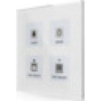

- KNX GLASS PUSH BUTTON II LITE
- FURTHER DOCUMENTS
- 1 CONTENT
- 2 OVERVIEW....4
- 3 COMMUNICATION OBJECTS....8
- 4 ETS PARAMETER....18
- 2 OVERVIEW
- 2.1 OVERVIEW DEVICES
- 2.2 FUNCTIONS
- EXTENSIVE BUTTON FUNCTIONS
- INNOVATIVE GROUP CONTROL
- MULTITOUCH-FUNCTION
- RGBW STATE LEDS
- INTEGRATED TEMPERATURE SENSOR (ONLY BE-GTLXTX.X1)
- SLAP FUNCTION
- LOGIC FUNCTIONS
- UPDATEABLE VIA DCA
- LONG FRAME SUPPORT
- 2.3 WIRING DIAGRAM
- 2.4 STRUCTURE & HANDLING
- 2.5 COMMISSIONING
- 3 COMMUNICATION OBJECTS
- 3.1 STANDARD SETTINGS OF THE COMMUNICATION OBJECTS
- 4 ETS PARAMETER
- 4.1 GENERAL SETTINGS
- 4.1.1 DEVICE SELECTION
- 4.1.2 GENERAL SETTINGS
- STARTUP TIME
- IN OPERATION
- BUTTON OPERATION
- NO. NAME/OBJECT FUNCTION LENGTH USAGE
- 4.2 BUTTON FUNCTIONS – GENERAL
- BUTTON ORIENTATION (ONLY BE-GTL4XX.01)
- BUTTON FUNCTIONS
- SLAP/CLEANING FUNCTION
- REACTION TIME ON KEYPRESS
- TIME FOR LONG KEYPRESS (BASIC SETTING)
- 4.3 BUTTON FUNCTIONS
- 4.3.1 IDENTICAL PARAMETER
- 4.3.1.1 LOCK OBJECT
- 4.3.1.2 BUTTON/OBJECT DESCRIPTION
- 4.3.2 SWITCH (GENERAL)
- EXAMPLE
- 4.3.2.1 SWITCHING WITH TWO-BUTTON FUNCTION
- 4.3.2.2 SUBFUNCTION: SWITCH
- 4.3.2.3 SUBFUNCTION: TOGGLE
- 4.3.2.4 SUBFUNCTION: SEND STATUS
- ☑ SINGLE-BUTTON FUNCTION
- 4.3.3 SEND VALUES
- 4.3.3.1 SUBFUNCTION: SEND VALUES
- ADDITIONAL OBJECT
- 4.3.3.2 SUBFUNCTION: TOGGLE VALUES/SCENES
- FUNCTIONAL PRINCIPLE
- DELAY BETWEEN SWITCHOVERS
- LONG KEYPRESS
- ACTION ON LONG KEYPRESS
- 4.3.3.3 SUBFUNCTION: SHIFT VALUE
- LOWER/UPPER LIMIT
- STEP WIDTH
- REPEATED SENDING WITH PRESSED BUTTON
- 4.3.3.4 SUBFUNCTION: SEND VALUES BY STATE
- 4.3.3.5 SUBFUNCTION: MULTITOUCH-FUNCTION
- OUTPUT OBJECTS
- 3./4. FUNCTION (LONG KEYPRESS)
- 4.3.4 SWITCH/SEND VALUES SHORT/LONG (WITH 2 OBJECTS)
- 4.3.5 SCENE
- 4.3.6 BLINDS/SHUTTER
- MDT SINGLE OBJECT CONTROL
- 4.3.7 DIMMING
- DIMMING AS A TWO-BUTTON FUNCTION
- DIMMING AS A SINGLE-BUTTON FUNCTION
- 4.3.8 SLAP/CLEANING FUNCTION
- CLEANING FUNCTION
- 4.4 STATUS LED
- 4.4.1 LED BASIC SETTING
- LED COLOUR ON BUTTON ACTIVATION
- GLOBAL BRIGHTNESS FOR LEDS
- LOCK OBJECT FOR LEDS
- SYNCHRONIZATION OBJECT FOR FLASHING LEDS
- THRESHOLD FOR MINIMUM/MAXIMUM BRIGHTNESS
- 4.4.2 LED 1 - 4
- CONTROL OF THE LED
- LED REACTS TO: INTERNAL OBJECT
- LED REACTS TO: EXTERNAL OBJECT
- DAY/NIGHT
- 4.4.2.1 PRIORITY
- 4.5 LOGIC
- 4.5.1 LOGIC BASIC SETTINGS
- 4.5.2 SETTING LOGIC 1 - 4
- FUNCTION/OBJECT DESCRIPTION
- SENDING CONDITION
- INVERT OUTPUT
- 4.5.3 SUBMENU - LOGIC 1 - 4
- EXTERNAL INPUTS
- INTERNAL INPUTS
- SEND VALUE ON BUTTON ACTIVATION
- 4.6 TEMPERATURE
- SENSOR INTERNAL/EXTERNAL
- SEND MEASURED VALUE CYCLICALLY
- SEND MEASUREMENT VALUE ON CHANGE
- ADJUSTMENT VALUE FOR INTERNAL TEMPERATURE
- TEMPERATURE FOR UPPER/LOWER MESSAGE VALUE
- 5 INDEX
- 5.1 LIST OF ILLUSTRATIONS
- 5.2 LIST OF TABLES
- 6 APPENDIX
- 6.1 LEGAL PROVISIONS
- 6.2 DISPOSAL
- 6.3 ASSEMBLY
- 6.4 HISTORY
Brand : MDT
Model : BE-GTL2TS.C1S
Category : Electrical switch